EP3859280A1 - Traffic lane line fitting method and system - Google Patents
Traffic lane line fitting method and system Download PDFInfo
- Publication number
- EP3859280A1 EP3859280A1 EP19866854.3A EP19866854A EP3859280A1 EP 3859280 A1 EP3859280 A1 EP 3859280A1 EP 19866854 A EP19866854 A EP 19866854A EP 3859280 A1 EP3859280 A1 EP 3859280A1
- Authority
- EP
- European Patent Office
- Prior art keywords
- lane
- road
- lane line
- vehicle
- coordinate system
- Prior art date
- Legal status (The legal status is an assumption and is not a legal conclusion. Google has not performed a legal analysis and makes no representation as to the accuracy of the status listed.)
- Pending
Links
Images


Classifications
-
- G—PHYSICS
- G01—MEASURING; TESTING
- G01C—MEASURING DISTANCES, LEVELS OR BEARINGS; SURVEYING; NAVIGATION; GYROSCOPIC INSTRUMENTS; PHOTOGRAMMETRY OR VIDEOGRAMMETRY
- G01C21/00—Navigation; Navigational instruments not provided for in groups G01C1/00 - G01C19/00
- G01C21/38—Electronic maps specially adapted for navigation; Updating thereof
- G01C21/3804—Creation or updating of map data
- G01C21/3807—Creation or updating of map data characterised by the type of data
- G01C21/3815—Road data
- G01C21/3819—Road shape data, e.g. outline of a route
-
- G—PHYSICS
- G01—MEASURING; TESTING
- G01C—MEASURING DISTANCES, LEVELS OR BEARINGS; SURVEYING; NAVIGATION; GYROSCOPIC INSTRUMENTS; PHOTOGRAMMETRY OR VIDEOGRAMMETRY
- G01C21/00—Navigation; Navigational instruments not provided for in groups G01C1/00 - G01C19/00
- G01C21/26—Navigation; Navigational instruments not provided for in groups G01C1/00 - G01C19/00 specially adapted for navigation in a road network
- G01C21/34—Route searching; Route guidance
- G01C21/36—Input/output arrangements for on-board computers
- G01C21/3626—Details of the output of route guidance instructions
- G01C21/3658—Lane guidance
-
- B—PERFORMING OPERATIONS; TRANSPORTING
- B60—VEHICLES IN GENERAL
- B60W—CONJOINT CONTROL OF VEHICLE SUB-UNITS OF DIFFERENT TYPE OR DIFFERENT FUNCTION; CONTROL SYSTEMS SPECIALLY ADAPTED FOR HYBRID VEHICLES; ROAD VEHICLE DRIVE CONTROL SYSTEMS FOR PURPOSES NOT RELATED TO THE CONTROL OF A PARTICULAR SUB-UNIT
- B60W30/00—Purposes of road vehicle drive control systems not related to the control of a particular sub-unit, e.g. of systems using conjoint control of vehicle sub-units
- B60W30/10—Path keeping
- B60W30/12—Lane keeping
-
- G—PHYSICS
- G01—MEASURING; TESTING
- G01C—MEASURING DISTANCES, LEVELS OR BEARINGS; SURVEYING; NAVIGATION; GYROSCOPIC INSTRUMENTS; PHOTOGRAMMETRY OR VIDEOGRAMMETRY
- G01C21/00—Navigation; Navigational instruments not provided for in groups G01C1/00 - G01C19/00
- G01C21/26—Navigation; Navigational instruments not provided for in groups G01C1/00 - G01C19/00 specially adapted for navigation in a road network
- G01C21/28—Navigation; Navigational instruments not provided for in groups G01C1/00 - G01C19/00 specially adapted for navigation in a road network with correlation of data from several navigational instruments
- G01C21/30—Map- or contour-matching
-
- G—PHYSICS
- G01—MEASURING; TESTING
- G01C—MEASURING DISTANCES, LEVELS OR BEARINGS; SURVEYING; NAVIGATION; GYROSCOPIC INSTRUMENTS; PHOTOGRAMMETRY OR VIDEOGRAMMETRY
- G01C21/00—Navigation; Navigational instruments not provided for in groups G01C1/00 - G01C19/00
- G01C21/26—Navigation; Navigational instruments not provided for in groups G01C1/00 - G01C19/00 specially adapted for navigation in a road network
- G01C21/34—Route searching; Route guidance
- G01C21/3407—Route searching; Route guidance specially adapted for specific applications
- G01C21/343—Calculating itineraries
-
- G—PHYSICS
- G01—MEASURING; TESTING
- G01C—MEASURING DISTANCES, LEVELS OR BEARINGS; SURVEYING; NAVIGATION; GYROSCOPIC INSTRUMENTS; PHOTOGRAMMETRY OR VIDEOGRAMMETRY
- G01C21/00—Navigation; Navigational instruments not provided for in groups G01C1/00 - G01C19/00
- G01C21/26—Navigation; Navigational instruments not provided for in groups G01C1/00 - G01C19/00 specially adapted for navigation in a road network
- G01C21/34—Route searching; Route guidance
- G01C21/3453—Special cost functions, i.e. other than distance or default speed limit of road segments
- G01C21/3461—Preferred or disfavoured areas, e.g. dangerous zones, toll or emission zones, intersections, manoeuvre types or segments such as motorways, toll roads or ferries
-
- G—PHYSICS
- G01—MEASURING; TESTING
- G01C—MEASURING DISTANCES, LEVELS OR BEARINGS; SURVEYING; NAVIGATION; GYROSCOPIC INSTRUMENTS; PHOTOGRAMMETRY OR VIDEOGRAMMETRY
- G01C21/00—Navigation; Navigational instruments not provided for in groups G01C1/00 - G01C19/00
- G01C21/38—Electronic maps specially adapted for navigation; Updating thereof
- G01C21/3885—Transmission of map data to client devices; Reception of map data by client devices
- G01C21/3889—Transmission of selected map data, e.g. depending on route
-
- B—PERFORMING OPERATIONS; TRANSPORTING
- B60—VEHICLES IN GENERAL
- B60W—CONJOINT CONTROL OF VEHICLE SUB-UNITS OF DIFFERENT TYPE OR DIFFERENT FUNCTION; CONTROL SYSTEMS SPECIALLY ADAPTED FOR HYBRID VEHICLES; ROAD VEHICLE DRIVE CONTROL SYSTEMS FOR PURPOSES NOT RELATED TO THE CONTROL OF A PARTICULAR SUB-UNIT
- B60W2556/00—Input parameters relating to data
- B60W2556/45—External transmission of data to or from the vehicle
- B60W2556/50—External transmission of data to or from the vehicle of positioning data, e.g. GPS [Global Positioning System] data
Definitions
- the present invention relates to the field of intelligent transportation, in particular to a lane line fitting method and system.
- ADS Autonomous Driving System
- the ADS senses a surrounding environment in real time by using an environment sensing system installed on a vehicle, and determines a drivable area of the vehicle through data returned by a sensor.
- Environment sensing contents can be divided into two main parts, namely, road information and target information, respectively.
- Lane line information in the road information can provide driving path information for the vehicle, which is convenient for the realization of functions such as lane changing and lane maintaining for lateral control.
- the lane line information can also provide a reference for screening a target in a road in the environment sensing system.
- lane line detection is crucial to ADS, and in order to ensure driving safety of an autonomous driving vehicle, the prior art requires that an environment sensing system acquires the lane line information around the vehicle as much as possible while sensing the surrounding environment.
- the lane lines directly output by the sensor may be multiple and relatively complex, and cannot be directly used for decision-making and control of a vehicle behavior.
- the present invention aims to provide a lane line fitting method to solve the technical problem that extracted lane lines are multiple and relatively complex in the prior art.
- a lane line fitting method comprises:
- the method may further comprise: acquiring a decision-making lane changing signal and/or navigation information for the current position of the vehicle, wherein the decision-making lane changing signal indicates the lane changing direction side of the vehicle, and the navigation information is used for indicating the road width unchanged side.
- the method may further comprise: setting the priority of determining the lane line offset reference based on the lane changing direction side, the road width unchanged side, the lane continuous side and the reference side of the driving coordinate system.
- the method may further comprise: determining an actual road working condition of the vehicle according to the map information, and selecting, according to the actual road working condition, one or more of the lane changing direction side, the road width unchanged side, the lane continuous side and the reference side of the driving coordinate system to determine the lane line offset reference.
- the actual road working condition and the selected lane line offset reference comprise any one of the following: in the case that the actual road working condition is a separated roadbed, a conventional ramp, a conventional main road, ramp bifurcation or departure from a high-speed lane, the lane changing direction side and/or the reference side of the driving coordinate system are/is selected to determine the lane line offset reference; in the case that the actual road working condition is main road narrowing, the road width unchanged side is selected to determine the lane line offset reference; and in the case that the actual road working condition is ramp merging or ramp-main road joining, the lane continuous side and/or the reference side of the driving coordinate system are/is selected to determine the lane line offset reference.
- the method may further comprise: completely or partially deleting, by combining the map information, a lane line that is outside the road boundary of the current road or affected by a road obstacle from the plurality of lane lines.
- the lane line fitting method according to the present invention has the following advantages: the lane line fitting method according to the embodiments of the present invention can accurately and quickly determine a lane line offset reference used for lane line fitting, and outputs an effective lane line based on the lane line offset reference, facilitates lane maintaining and other controls, solves the problem that extracted lane lines are numerous and relatively complex in the prior art, can be adapted to different road scenes, and has high processing efficiency of lane line algorithm.
- Another object of the present invention is to provide a lane line fitting system to solve the technical problem that extracted lane lines are multiple and relatively complex in the prior art.
- a lane line fitting system comprises:
- the information acquisition unit may be further used for acquiring a decision-making lane changing signal and/or navigation information for the current position of the vehicle, wherein the decision-making lane changing signal indicates the lane changing direction side of the vehicle, and the navigation information is used for indicating the road width unchanged side.
- the system may further comprise: a priority setting unit, used for setting the priority of determining the lane line offset reference based on the lane changing direction side, the road width unchanged side, the lane continuous side and the reference side of the driving coordinate system.
- the reference determination unit is further electrically connected to the priority setting unit, and used for determining the lane line offset reference based on the priority, set by the priority setting unit, of determining the lane line offset reference based on the lane changing direction side, the road width unchanged side, the lane continuous side and the reference side of the driving coordinate system.
- the actual road working condition and the selected lane line offset reference comprise any one of the following: in the case that the actual road working condition is a separated roadbed, a conventional ramp, a conventional main road, ramp bifurcation or departure from a high-speed lane, the lane changing direction side and/or the reference side of the driving coordinate system are/is selected to determine the lane line offset reference; in the case that the actual road working condition is main road narrowing, the road width unchanged side is selected to determine the lane line offset reference; and in the case that the actual road working condition is ramp merging or ramp-main road joining, the lane continuous side and/or the reference side of the driving coordinate system are/is selected to determine the lane line offset reference.
- system may further comprise: a lane line screening unit, electrically connected to the lane line fitting unit, and used for completely or partially deleting, by combining the map information, a lane line that is outside the road boundary of the current road or affected by a road obstacle from the plurality of lane lines.
- a lane line screening unit electrically connected to the lane line fitting unit, and used for completely or partially deleting, by combining the map information, a lane line that is outside the road boundary of the current road or affected by a road obstacle from the plurality of lane lines.
- the lane line fitting system and the aforementioned lane line fitting method have the same advantages over the prior art, and details are not described here.
- Another object of the present invention is to provide a machine-readable storage medium, wherein an instruction is stored on the machine-readable storage medium, and the instruction is used for causing a controller to execute the above-mentioned lane line fitting method.
- connection is used to describe the signal connection between two components, such as a control signal and a feedback signal, and an electrical power connection between two components.
- connection involved in the embodiments of the present invention can be a wired connection or a wireless connection, and the “electrical connection” involved can be a direct electrical connection between two components or an indirect electrical connection through another component.
- the map information comprises the number of lanes, a road width and line point information of lane lines on two sides of the vehicle.
- the map information can further comprise a road type, road feature points, a lane width, and the like.
- the road feature points are points that can represent a specific position of a road in a road scene, such as the start point and end point of a certain road section.
- the map information is preferably high-precision map information.
- the high-precision map information can show the above-mentioned road type, number of lanes, road width, road feature points, and line points of the lane lines on two sides of the vehicle, lane width and other information.
- the high-precision map divides the road into a set of map points section by section, and the map output will divide the road from the position where the road changes, and will also give the relevant map information of the current road and the next road section.
- Step S120 it is determined, from among the lane lines on two sides of the vehicle, that a lane line on one side, consistent with the direction indicated by at least one of the following, is a lane line offset reference used for lane line fitting:
- Step S130 offsetting based on the lane line offset reference to generate a plurality of lane lines of the vehicle.
- LaneWidth_m represents the lane width (generally, the default lane width is 3.75m).
- the lane lines on two sides of the vehicle in the embodiment of the present invention refer to the left lane line and the right lane line adjacent to the vehicle, and do not comprise the left-left lane line(that is, lane line further to the left), the right-right lane line(that is, lane line further to the right), etc.
- the plurality of lane lines mentioned here comprise lane lines on two sides of the vehicle, as well as a left-left lane line and a right-right lane line that are lanes to the left or right of the lane lines on two sides of the vehicle, etc.
- the error of the fitted lane line is large due to the error caused by its own fitting using the fitted lane line equation, and the lane line information of the original high-precision map is also given in the form of continuous points. Therefore, the operation in the form of points is maintained during the intelligent lane line offset to ensure equidistant offset, and the fitting operation is not performed three times until the final lane line information is given and given in the form of cubic equation parameters.
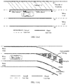
- FIG. 3 is a schematic diagram of an example of lane line fitting based on a lane changing direction side according to an embodiment of the present invention.
- the lane line fitting rule in the lane changing state is as follows: according to the position points, output by the high-precision map, of the lane lines on two sides of the vehicle, the high-precision map point information (the high-precision map point position of 200m ahead and 80m behind) on the lane changing direction side is selected to assign the corresponding side lane line; at this time, the vehicle is in a leftwards lane changing state, then position points on the left side of the vehicle on the high-precision map are assigned R1, and R1 is used as the lane line offset reference; then according to the lane width information on the left side and right side of the current position and the lane width information at the next 100m of the current lane, position point offset processing is performed to obtain L1 and L2, and then the points on the corresponding lane line are fitted three times to obtain the lane line equation.
- the high-precision map only outputs the width at the next 100m of the current lane in which the vehicle is located and the lane width information on the left and right side of the current position of the vehicle, and the left-left lane width information cannot be obtained, so the offset is temporarily based on a fixed 3.75m.
- FIG. 4 is a schematic diagram of an example of lane line fitting based on a reference side of a driving coordinate system according to an embodiment of the present invention.
- the lane line fitting rule in the driving coordinate system is as follows: according to the established driving coordinate system, the direction information (whether the driving coordinate system is established on the left side or the right side of the road) of the reference side of the driving coordinate system can be obtained; according to the position points, output by the high-precision map, of the lane lines on two sides of the vehicle, the high-precision map point information (the high-precision map point position of 200m ahead and 80m behind) on the direction side of the reference side of the driving coordinate system is selected to assign the corresponding side lane line; at this time, the vehicle is in a lane maintaining state, the reference side of the driving coordinate system is on the right side of the road, and R1 is used as the lane line offset reference; then according to the lane width information on the left side and right side of the current position and the lane width information at the next 100m of
- FIG. 5 is a schematic diagram of an example of lane line fitting based on a road width unchanged side according to an embodiment of the present invention.
- the lane line fitting rule with the road width unchanged side as a reference is as follows: since a navigation signal can indicate a change in width of the road ahead (narrowing on the left side, widening on the left side, narrowing on the right side, and widening on the right side); according to the position points, output by the high-precision map, of the lane lines on two sides of the vehicle, the high-precision map point information (the high-precision map point position of 200m ahead and 80m behind) on the road width unchanged side is selected to assign the corresponding side lane line; as shown in FIG.
- the road ahead is narrowing on the left side, then the position points on the right side of the vehicle on the high-precision map are assigned R1 as the lane line offset reference; then according to the lane width information on the left side and right side of the position at the next 100m and the lane width information at the next 100m of the current lane, position point offset processing is performed to obtain other lane lines, and then the points on the corresponding lane line are fitted three times to obtain the lane line equation.
- the lane line fitting method according to the embodiment of the present invention can further comprise: setting the priority of determining the lane line offset reference based on the lane changing direction side, the road width unchanged side, the lane continuous side and the reference side of the driving coordinate system.
- FIG. 7 is a schematic diagram of an example of lane line fitting by the priority of determining the lane line offset reference based on the lane changing direction side, the road width unchanged side, the lane continuous side and the reference side of the driving coordinate system according to an embodiment of the present invention.
- the order of the priority from high to low is: the lane changing direction side, the road width unchanged side, the lane continuous side, the reference side of the driving coordinate system.
- the method can comprise the following steps: Step S701, judging whether there is a decision-making lane changing signal, if so, performing the lane line fitting with the lane changing direction side as the reference, otherwise performing step S702.
- Step S702 judging whether road narrowing or widening occurs, if so, performing the lane line fitting with the road width unchanged side as the reference, otherwise performing step S703.
- the lane line fitting is performed with the road width unchanged side as the reference, it is necessary to combine actual road working conditions, such as whether the road is widening or narrowing, whether the road widening end point is passed, or whether the left side or right side is widening or narrowing, etc., to determine the lane line offset reference, and then fit the lane line.
- the road is narrowing
- the lane line on the right side is used as the lane line offset reference for offsetting other lane lines
- the lane line on the left side is used as the lane line offset reference for offsetting other lane lines.
- a state signal can be given to the decision-making system of the autonomous driving vehicle at the same time.
- the road widening end point is passed; if so, the left side is widening and the lane line on the right side is used as the lane line offset reference for offsetting other lane lines; if the right side is widening, the lane line on the left side is used as the lane line offset reference for offsetting other lane lines; if the road widening end point is not passed, if the left side is widening, the lane line on the right side is used as the lane line offset reference for offsetting for the original road width to obtain other lane lines; if the right side is widening, the lane line on the left side is used as the lane line offset reference for offsetting for the original road width to obtain other lane lines.
- step S704 is directly executed.
- Step S704 performing the lane line fitting with the reference side of the driving coordinate system as the reference.
- the above four lane line fitting schemes based on the lane changing direction side, the reference side of the driving coordinate system, the road width unchanged side and the lane continuous side are applicable to a variety of road working conditions.
- the lane line fitting method further comprises: determining an actual road working condition of the vehicle according to the map information, and selecting, according to the actual road working condition, one or more of the lane changing direction side, the road width unchanged side, the lane continuous side and the reference side of the driving coordinate system to determine the lane line offset reference.
- the actual road working condition and the selected lane line offset reference can comprise any one of the following:
- FIG. 10 (a) is a schematic diagram of lane line fitting for ramp merging
- FIG. 10 (b) is a schematic diagram of lane line fitting for ramp-main road joining.
- the lane line R1 on one side of the direction of the driving coordinate system is selected as the lane line offset reference for offsetting to obtain other lane lines.
- the number of lanes on the left side of the vehicle is discontinuous (the number of lanes changes), so the lane line R1 of the continuous lane should be used as the lane line offset reference for offsetting to obtain other lane lines.
- the lane line R1 on one side of the direction of the driving coordinate system is first selected as the lane line offset reference for offsetting to obtain other lane lines.
- the driving coordinate system should be switched to the leftmost side of the road, so that the lane line L1 on the left side is changed as the lane line offset reference for offsetting to obtain other lane lines.
- the number of lanes on the left side of the vehicle is discontinuous (the number of lanes changes), so the lane line R1 of the continuous lane should be used as the lane line offset reference for offsetting to obtain other lane lines.
- the number of lanes on the right side is discontinuous (the number of lanes changes), so the lane line L1 of the continuous lane on the left side should be used as the lane line offset reference for offsetting to obtain other lane lines.
- the lane line fitting method in the embodiment of the present invention can further comprise: completely or partially deleting, by combining the map information, a lane line that is outside the road boundary of the current road or affected by a road obstacle from the plurality of lane lines.
- FIG. 11(a) is a schematic diagram of deleting a lane line outside the road boundary of the current road. It can be seen that the fitted L2 does not actually exist, and it should be considered to delete L2.
- 11(b) is a schematic diagram of deleting a lane line affected by a road obstacle. It can be seen that part of the fitted L2 is affected by obstacles, and the lane formed by this part of L2 and L1 is actually not passable, so this part of the fitted L2 does not match the actual road plan, and it should be considered to delete this part of unreasonable fitting in L2.
- FIG. 12 is a structural schematic diagram of a lane line fitting system according to an embodiment of the present invention.
- the lane line fitting system is based on the same inventive idea as the above-mentioned embodiment of the lane line fitting method.
- the lane line fitting system comprises:
- the lane line fitting system further comprises: a priority setting unit 4, used for setting the priority of determining the lane line offset reference based on the lane changing direction side, the road width unchanged side, the lane continuous side and the reference side of the driving coordinate system.
- the reference determination unit 2 is further electrically connected to the priority setting unit 4, and used for determining the lane line offset reference based on the priority, set by the priority setting unit, of determining the lane line offset reference based on the lane changing direction side, the road width unchanged side, the lane continuous side and the reference side of the driving coordinate system.
- the lane line fitting system further comprises: a road working condition determination unit 5, used for determining an actual road working condition of the vehicle according to the map information.
- the reference determination unit 2 is also electrically connected to the road working condition determination unit 5, and used for selecting, according to the actual road working condition, one or more of the lane changing direction side, the road width unchanged side, the lane continuous side and the reference side of the driving coordinate system to determine the lane line offset reference.
- the lane line fitting system further comprises: a lane line screening unit 6, electrically connected to the lane line fitting unit 3, and used for completely or partially deleting, by combining the map information, a lane line that is outside the road boundary of the current road or affected by a road obstacle from the plurality of lane lines.
- the program is stored in a storage medium, and comprises several instructions for causing a single chip computer, a chip, or a processor to execute all or part of the steps of the method described in each embodiment of the present application.
- the aforementioned storage medium comprises various kinds of mediums that may store program codes, such as a U disk, a mobile hard disk, a Read-Only Memory (ROM), a Random Access Memory (RAM), a magnetic disk or an optical disk.
- any combination of the various embodiments of the present invention can be made therebetween, which, as long as not violating the idea of the embodiments of the present invention, shall likewise be considered as contents disclosed in the embodiments of the present invention.
Landscapes
- Engineering & Computer Science (AREA)
- Radar, Positioning & Navigation (AREA)
- Remote Sensing (AREA)
- Automation & Control Theory (AREA)
- Physics & Mathematics (AREA)
- General Physics & Mathematics (AREA)
- Transportation (AREA)
- Mechanical Engineering (AREA)
- Traffic Control Systems (AREA)
- Navigation (AREA)
- Control Of Driving Devices And Active Controlling Of Vehicle (AREA)
Abstract
Description
- The present invention relates to the field of intelligent transportation, in particular to a lane line fitting method and system.
- At present, vehicles with an Autonomous Driving System (ADS) are gradually brought to the market, which greatly promotes the development of intelligent transportation. The ADS senses a surrounding environment in real time by using an environment sensing system installed on a vehicle, and determines a drivable area of the vehicle through data returned by a sensor. Environment sensing contents can be divided into two main parts, namely, road information and target information, respectively. Lane line information in the road information can provide driving path information for the vehicle, which is convenient for the realization of functions such as lane changing and lane maintaining for lateral control. In addition, the lane line information can also provide a reference for screening a target in a road in the environment sensing system.
- Therefore, it can be known that lane line detection is crucial to ADS, and in order to ensure driving safety of an autonomous driving vehicle, the prior art requires that an environment sensing system acquires the lane line information around the vehicle as much as possible while sensing the surrounding environment. However, when the road is changed such as bifurcated or joins, the lane lines directly output by the sensor may be multiple and relatively complex, and cannot be directly used for decision-making and control of a vehicle behavior.
- In view of this, the present invention aims to provide a lane line fitting method to solve the technical problem that extracted lane lines are multiple and relatively complex in the prior art.
- To achieve the above object, a technical solution of the present invention is implemented as follows:
A lane line fitting method comprises: - acquiring map information for a current position of a vehicle, wherein the map information comprises the number of lanes, a road width and line point information of lane lines on two sides of the vehicle;
- determining, from among the lane lines on two sides of the vehicle, a lane line on one side, consistent with the direction indicated by at least one of the following, to be a lane line offset reference used for lane line fitting: a lane changing direction side, indicating the side to which the vehicle is expected to perform lane changing in the current road; a reference side of a driving coordinate system, wherein the driving coordinate system takes a road boundary line on one side of the road on which the vehicle is located as a reference, and takes a road guide line direction and a direction following a left-hand rule with the road guide line direction as two axes; a road width unchanged side, indicating the side where the road width does not change in the road ahead of the vehicle; and a lane continuous side, indicating the side where the lane continuity does not change in the current road; and
- offsetting based on the lane line offset reference to generate a plurality of lane lines of the vehicle, and performing curve fitting on a set of line points on the plurality of generated lane lines to obtain a corresponding lane line equation.
- Furthermore, the method may further comprise: acquiring a decision-making lane changing signal and/or navigation information for the current position of the vehicle, wherein the decision-making lane changing signal indicates the lane changing direction side of the vehicle, and the navigation information is used for indicating the road width unchanged side.
- Furthermore, the method may further comprise: setting the priority of determining the lane line offset reference based on the lane changing direction side, the road width unchanged side, the lane continuous side and the reference side of the driving coordinate system.
- Furthermore, the method may further comprise: determining an actual road working condition of the vehicle according to the map information, and selecting, according to the actual road working condition, one or more of the lane changing direction side, the road width unchanged side, the lane continuous side and the reference side of the driving coordinate system to determine the lane line offset reference. Wherein, the actual road working condition and the selected lane line offset reference comprise any one of the following: in the case that the actual road working condition is a separated roadbed, a conventional ramp, a conventional main road, ramp bifurcation or departure from a high-speed lane, the lane changing direction side and/or the reference side of the driving coordinate system are/is selected to determine the lane line offset reference; in the case that the actual road working condition is main road narrowing, the road width unchanged side is selected to determine the lane line offset reference; and in the case that the actual road working condition is ramp merging or ramp-main road joining, the lane continuous side and/or the reference side of the driving coordinate system are/is selected to determine the lane line offset reference.
- Furthermore, the method may further comprise: completely or partially deleting, by combining the map information, a lane line that is outside the road boundary of the current road or affected by a road obstacle from the plurality of lane lines.
- Compared with the prior art, the lane line fitting method according to the present invention has the following advantages: the lane line fitting method according to the embodiments of the present invention can accurately and quickly determine a lane line offset reference used for lane line fitting, and outputs an effective lane line based on the lane line offset reference, facilitates lane maintaining and other controls, solves the problem that extracted lane lines are numerous and relatively complex in the prior art, can be adapted to different road scenes, and has high processing efficiency of lane line algorithm.
- Another object of the present invention is to provide a lane line fitting system to solve the technical problem that extracted lane lines are multiple and relatively complex in the prior art.
- To achieve the above object, a technical solution of the present invention is implemented as follows:
A lane line fitting system comprises: - an information acquisition unit, used for acquiring map information for a current position of a vehicle, wherein the map information comprises the number of lanes, a road width and line point information of lane lines on two sides of the vehicle;
- a reference determination unit, electrically connected to the information acquisition unit, and used for determining, from among the lane lines on two sides of the vehicle, a lane line on one side, consistent with the direction indicated by at least one of the following, to be a lane line offset reference used for lane line fitting: a lane changing direction side, indicating the side to which the vehicle is expected to perform lane changing in the current road; a reference side of a driving coordinate system, wherein the driving coordinate system takes a road boundary line on one side of the road on which the vehicle is located as a reference, and takes a road guide line direction and a direction following a left-hand rule with the road guide line direction as two axes; a road width unchanged side, indicating the side where the road width does not change in the road ahead of the vehicle; and a lane continuous side, indicating the side where the lane continuity does not change in the current road; and
- a lane line fitting unit, electrically connected to the information acquisition unit and the reference determination unit, and used for offsetting based on the lane line offset reference to generate a plurality of lane lines of the vehicle, and performing curve fitting on a set of line points on the plurality of generated lane lines to obtain a corresponding lane line equation.
- Furthermore, the information acquisition unit may be further used for acquiring a decision-making lane changing signal and/or navigation information for the current position of the vehicle, wherein the decision-making lane changing signal indicates the lane changing direction side of the vehicle, and the navigation information is used for indicating the road width unchanged side.
- Furthermore, the system may further comprise: a priority setting unit, used for setting the priority of determining the lane line offset reference based on the lane changing direction side, the road width unchanged side, the lane continuous side and the reference side of the driving coordinate system. Wherein the reference determination unit is further electrically connected to the priority setting unit, and used for determining the lane line offset reference based on the priority, set by the priority setting unit, of determining the lane line offset reference based on the lane changing direction side, the road width unchanged side, the lane continuous side and the reference side of the driving coordinate system.
- Furthermore, the system may further comprise: a road working condition determination unit, used for determining an actual road working condition of the vehicle according to the map information, wherein the reference determination unit is also electrically connected to the road working condition determination unit, and used for selecting, according to the actual road working condition, one or more of the lane changing direction side, the road width unchanged side, the lane continuous side and the reference side of the driving coordinate system to determine the lane line offset reference. Wherein, the actual road working condition and the selected lane line offset reference comprise any one of the following: in the case that the actual road working condition is a separated roadbed, a conventional ramp, a conventional main road, ramp bifurcation or departure from a high-speed lane, the lane changing direction side and/or the reference side of the driving coordinate system are/is selected to determine the lane line offset reference; in the case that the actual road working condition is main road narrowing, the road width unchanged side is selected to determine the lane line offset reference; and in the case that the actual road working condition is ramp merging or ramp-main road joining, the lane continuous side and/or the reference side of the driving coordinate system are/is selected to determine the lane line offset reference.
- Furthermore, the system may further comprise: a lane line screening unit, electrically connected to the lane line fitting unit, and used for completely or partially deleting, by combining the map information, a lane line that is outside the road boundary of the current road or affected by a road obstacle from the plurality of lane lines.
- The lane line fitting system and the aforementioned lane line fitting method have the same advantages over the prior art, and details are not described here.
- Another object of the present invention is to provide a machine-readable storage medium, wherein an instruction is stored on the machine-readable storage medium, and the instruction is used for causing a controller to execute the above-mentioned lane line fitting method.
- Other features and advantages of the present invention will be described in detail in the specific embodiments below.
- The drawings, which form a part of the present invention, are used to provide a further understanding of the present invention. The exemplary embodiments of the present invention and the description thereof are used to explain the present invention, and do not constitute an improper limitation on the present invention. In the drawings:
-
FIG. 1 is a schematic flowchart of a lane line fitting method according to an embodiment of the present invention; -
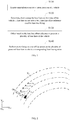
FIG. 2 is a schematic diagram of a driving coordinate system XFOFYF, a global coordinate system XGOGYG and a vehicle coordinate system XHOHYH according to an embodiment of the present invention. -
FIG. 3 is a schematic diagram of an example of lane line fitting based on a lane changing direction side according to an embodiment of the present invention; -
FIG. 4 is a schematic diagram of an example of lane line fitting based on a reference side of a driving coordinate system according to an embodiment of the present invention; -
FIG. 5 is a schematic diagram of an example of lane line fitting based on a road width unchanged side according to an embodiment of the present invention; -
FIG. 6 is a schematic diagram of an example of lane line fitting based on a lane continuous side according to an embodiment of the present invention; -
FIG. 7 is a schematic diagram of an example of lane line fitting by the priority of determining the lane line offset reference based on the lane changing direction side, the road width unchanged side, the lane continuous side and the reference side of the driving coordinate system according to an embodiment of the present invention; -
FIG. 8(a) is a schematic diagram of lane line fitting for a separated roadbed,FIG. 8(b) is a schematic diagram of lane line fitting for a conventional ramp,FIG. 8(c) is a schematic diagram of lane line fitting for a conventional main road,FIG. 8(d) is a schematic diagram of lane line fitting for ramp bifurcation, andFIG. 8(e) is a schematic diagram of lane line fitting for departure from a high-speed lane; -
FIG. 9 is a schematic diagram of lane line fitting for main road narrowing; -
FIG. 10 (a) is a schematic diagram of lane line fitting for ramp merging, andFIG. 10 (b) is a schematic diagram of lane line fitting for ramp-main road joining; -
FIG. 11(a) is a schematic diagram of deleting a lane line outside the road boundary of the current road, andFIG. 11(b) is a schematic diagram of deleting a lane line affected by a road obstacle; and -
FIG. 12 is a structural schematic diagram of a lane line fitting system according to an embodiment of the present invention. - It should be noted that, in the case of no conflict, the embodiments of the present invention and features in the embodiments can be combined with each other.
- In the embodiments of the present invention, "electrical connection" is used to describe the signal connection between two components, such as a control signal and a feedback signal, and an electrical power connection between two components. In addition, the "connection" involved in the embodiments of the present invention can be a wired connection or a wireless connection, and the "electrical connection" involved can be a direct electrical connection between two components or an indirect electrical connection through another component.
- The present invention will be described in detail below with reference to the drawings and embodiments.
-
FIG. 1 is a schematic flowchart of a lane line fitting method according to an embodiment of the present invention, wherein the lane line fitting method is used for an autonomous driving vehicle. As shown inFIG. 1 , the lane line fitting method comprises:
Step S110, acquiring map information for a current position of a vehicle. - The map information comprises the number of lanes, a road width and line point information of lane lines on two sides of the vehicle. In a more preferred embodiment, the map information can further comprise a road type, road feature points, a lane width, and the like. The road feature points are points that can represent a specific position of a road in a road scene, such as the start point and end point of a certain road section.
- The map information is preferably high-precision map information. Those skilled in the art know that the high-precision map information can show the above-mentioned road type, number of lanes, road width, road feature points, and line points of the lane lines on two sides of the vehicle, lane width and other information. The high-precision map divides the road into a set of map points section by section, and the map output will divide the road from the position where the road changes, and will also give the relevant map information of the current road and the next road section.
- Step S120, determining, from among the lane lines on two sides of the vehicle, a lane line on one side to be a lane line offset reference used for lane line fitting.
- Specifically, in Step S120, it is determined, from among the lane lines on two sides of the vehicle, that a lane line on one side, consistent with the direction indicated by at least one of the following, is a lane line offset reference used for lane line fitting:
- 1) A lane changing direction side, indicating the side to which the vehicle is expected to perform lane changing in the current road.
The lane line fitting method according to the present invention can further comprise: acquiring a decision-making lane changing signal for the current position of the vehicle, wherein the decision-making lane changing signal indicates the lane changing direction side of the vehicle.
The decision-making lane changing signal can be given by a decision-making system of the autonomous driving vehicle, wherein the decision-making system determines whether to perform lane changing of the vehicle according to current vehicle data, road data, target data and the like, and gives a corresponding decision-making lane changing signal, such as lane maintaining (not changing a lane), leftwards lane changing with lane changing uncompleted, rightwards lane changing with lane changing uncompleted, and having a lane changing signal with lane changing completed. - 2) A reference side of a driving coordinate system.
The driving coordinate system takes a road boundary line on one side of the road on which the vehicle is located as a reference, and takes a road guide line direction and a direction following a left-hand rule with the road guide line direction as two axes.FIG. 2 is a schematic diagram of a driving coordinate system XFOFYF, a global coordinate system XGOGYG and a vehicle coordinate system XHOHYH according to an embodiment of the present invention. As shown inFIG. 2 , the global coordinate system XGOGYG is based on the geodetic coordinate system, XG points to the north, YG points to the east, the angle direction is clockwise as positive, and the angle range is [0, 360°]. Map lane line information and the like are given based on the global coordinate system. The vehicle coordinate system XHOHYH is based on the vehicle, wherein XH points to the longitudinal axis of the vehicle and YH points to the horizontal axis of the vehicle. Following the right-hand rule, counterclockwise is positive. The output information of the sensors of the camera, lidar, and millimeter wave radar on the vehicle is given based on the vehicle coordinate system. According to the definitions of the global coordinate system and the vehicle coordinate system, the driving coordinate system according to the embodiment of the present invention can be correspondingly expressed as XFOFYF, which is a coordinate system established on the road boundary line and completely consistent with the road trend. After the origin OF(XFo, YFo ) is determined, the arc length distance between each point on the road boundary line and the driving coordinate origin OF (XFo, YFo ) can be calculated as the driving ordinate XFi of each point. Therefore, the longitudinal axis XF of the driving coordinate system is completely consistent with the road trend, and the driving abscissa of each reference line point is YFi =0. Thus, the vehicle position, the lane line, the target and the like can be given based on the driving coordinate system, particularly in the bend working condition, the arc length distance of the real bend is taken as target distance information to be output, and compared with the lane coordinate system, error in target area attribute and effective distance can be avoided. In addition, if each lane line is described by a point in the driving coordinate system, it is easy to know that the abscissas of points on the lane line in the driving coordinate system are the same, and only the ordinates are different, for example, referring toFIG. 2 , the ordinates increase sequentially on the selected lane line, and the abscissas are all 3.75. Therefore, the lane line can be described by using the ordinates of the lane line in the driving coordinate system.
Based on the established driving coordinate system, the direction information (whether the driving coordinate system is established on the left side or the right side of the road) on the reference side of the driving coordinate system can be obtained, and then according to the position points, output by the high-precision map, of the lane lines on two sides of the vehicle, the side consistent with the reference side of the driving coordinate system in direction is determined as a lane line offset reference.
In addition, the reference side of the driving coordinate system can be switched, and the switching rule is, for example, taking a preset default road boundary line as the reference line; switching to a road boundary line on the navigation direction side indicated by the navigation direction information; maintaining the current reference line unchanged if the road on which the vehicle is currently located is a ramp, and switching to the default road boundary line if the road on which the vehicle is currently located is a main road. - 3) A road width unchanged side, indicating the side where the road width does not change in the road ahead of the vehicle.
The lane line fitting method according to the present invention can further comprise: acquiring navigation information for the current position of the vehicle, wherein the navigation information is used for indicating the road width unchanged side. Specifically, the navigation information is obtained by, for example, a vehicle-mounted navigation system having a GPS positioning function, and can indicate a change (narrowing on the left side, widening on the left side, narrowing on the right side, and widening on the right side, etc.) in width of the road ahead in real time, and then according to the position points, output by the high-precision map, of the lane lines on two sides of the vehicle, determine the side consistent with the road width unchanged side as the lane line offset reference. - 4) A lane continuous side, indicating the side where the lane continuity does not change in the current road.
- For example, in the case of a freeway with no change in the road width but a change in the number of lanes, there is certainly a case where the lane is continuous on one side and discontinuous on the other side, and thus the lane line offset reference can be determined according to the lane continuous side.
- Step S130, offsetting based on the lane line offset reference to generate a plurality of lane lines of the vehicle.
- Preferably, step S130 can comprise the following steps: calculating a heading angle of each line point on the lane line offset reference; and offsetting for the preset lane width to the left and/or right based on a coordinate, heading angle and preset lane width corresponding to each line point on the lane line offset reference to generate a plurality of lane lines of the vehicle. The calculation equation is explained as follows:
Original points: (x(1), x(2), x(3),..., x(n); y(1), y(2), y(3),..., y(n)). - Calculate heading angle information:


- The offset equation for points on the lane line (offset to the right) is as follows:


- LaneWidth_m represents the lane width (generally, the default lane width is 3.75m).
- It should be noted that the lane lines on two sides of the vehicle in the embodiment of the present invention refer to the left lane line and the right lane line adjacent to the vehicle, and do not comprise the left-left lane line(that is, lane line further to the left), the right-right lane line(that is, lane line further to the right), etc. The plurality of lane lines mentioned here comprise lane lines on two sides of the vehicle, as well as a left-left lane line and a right-right lane line that are lanes to the left or right of the lane lines on two sides of the vehicle, etc.
- Step S140, performing curve fitting on a set of line points on the plurality of generated lane lines to obtain a corresponding lane line equation.
- Preferably, the error of the fitted lane line is large due to the error caused by its own fitting using the fitted lane line equation, and the lane line information of the original high-precision map is also given in the form of continuous points. Therefore, the operation in the form of points is maintained during the intelligent lane line offset to ensure equidistant offset, and the fitting operation is not performed three times until the final lane line information is given and given in the form of cubic equation parameters.
- The following will give a comprehensive description by exemplifying the lane line fitting method of the embodiment of the present invention. In this example, the map information is exemplified by a high-precision map. For ease of description, four examples of lane line fitting based on the lane changing direction side, the driving coordinate system, the road width unchanged side and the lane continuous side are respectively described below.
-
FIG. 3 is a schematic diagram of an example of lane line fitting based on a lane changing direction side according to an embodiment of the present invention. In this example, the lane line fitting rule in the lane changing state is as follows: according to the position points, output by the high-precision map, of the lane lines on two sides of the vehicle, the high-precision map point information (the high-precision map point position of 200m ahead and 80m behind) on the lane changing direction side is selected to assign the corresponding side lane line; at this time, the vehicle is in a leftwards lane changing state, then position points on the left side of the vehicle on the high-precision map are assigned R1, and R1 is used as the lane line offset reference; then according to the lane width information on the left side and right side of the current position and the lane width information at the next 100m of the current lane, position point offset processing is performed to obtain L1 and L2, and then the points on the corresponding lane line are fitted three times to obtain the lane line equation. Here, the high-precision map only outputs the width at the next 100m of the current lane in which the vehicle is located and the lane width information on the left and right side of the current position of the vehicle, and the left-left lane width information cannot be obtained, so the offset is temporarily based on a fixed 3.75m. -
FIG. 4 is a schematic diagram of an example of lane line fitting based on a reference side of a driving coordinate system according to an embodiment of the present invention. In this example, the lane line fitting rule in the driving coordinate system is as follows: according to the established driving coordinate system, the direction information (whether the driving coordinate system is established on the left side or the right side of the road) of the reference side of the driving coordinate system can be obtained; according to the position points, output by the high-precision map, of the lane lines on two sides of the vehicle, the high-precision map point information (the high-precision map point position of 200m ahead and 80m behind) on the direction side of the reference side of the driving coordinate system is selected to assign the corresponding side lane line; at this time, the vehicle is in a lane maintaining state, the reference side of the driving coordinate system is on the right side of the road, and R1 is used as the lane line offset reference; then according to the lane width information on the left side and right side of the current position and the lane width information at the next 100m of the current lane, position point offset processing is performed to obtain other lane lines, and then the points on the corresponding lane line are fitted three times to obtain the lane line equation. -
FIG. 5 is a schematic diagram of an example of lane line fitting based on a road width unchanged side according to an embodiment of the present invention. In this example, the lane line fitting rule with the road width unchanged side as a reference is as follows: since a navigation signal can indicate a change in width of the road ahead (narrowing on the left side, widening on the left side, narrowing on the right side, and widening on the right side); according to the position points, output by the high-precision map, of the lane lines on two sides of the vehicle, the high-precision map point information (the high-precision map point position of 200m ahead and 80m behind) on the road width unchanged side is selected to assign the corresponding side lane line; as shown inFIG. 5 , the road ahead is narrowing on the left side, then the position points on the right side of the vehicle on the high-precision map are assigned R1 as the lane line offset reference; then according to the lane width information on the left side and right side of the position at the next 100m and the lane width information at the next 100m of the current lane, position point offset processing is performed to obtain other lane lines, and then the points on the corresponding lane line are fitted three times to obtain the lane line equation. -
FIG. 6 is a schematic diagram of an example of lane line fitting based on a lane continuous side according to an embodiment of the present invention. In this example, the lane line fitting rule with the lane continuous side as a reference is as follows: due to the case of a freeway with no change in the road width but a change in the number of lanes, there is certainly a case where the lane is continuous on one side and discontinuous on the other side; according to the position points, output by the high-precision map, of the lane lines on two sides of the vehicle, the high-precision map point information (the high-precision map point position of 200m ahead and 80m behind) on the lane continuous side is selected to assign the corresponding side lane line; as shown in the figure, at this time, the vehicle is in a lane maintaining state, and the lane on the right side is continuous, then the position points on the right side of the vehicle on the high-precision map are assigned R1 as the lane line offset reference; then according to the lane width information on the left side and right side of the current position and the lane width information at the next 100m of the current lane, position point offset processing is performed to obtain other lane lines, and then the points on the corresponding lane line are fitted three times to obtain the lane line equation. - Here, some conditions may apply to more than one of the above lane line fitting schemes based on the lane changing direction side, the reference side of the driving coordinate system, the road width unchanged side and the lane continuous side. To avoid repetitive execution of lane line fitting, in a preferred embodiment, the lane line fitting method according to the embodiment of the present invention can further comprise: setting the priority of determining the lane line offset reference based on the lane changing direction side, the road width unchanged side, the lane continuous side and the reference side of the driving coordinate system.
-
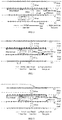
FIG. 7 is a schematic diagram of an example of lane line fitting by the priority of determining the lane line offset reference based on the lane changing direction side, the road width unchanged side, the lane continuous side and the reference side of the driving coordinate system according to an embodiment of the present invention. In this example, the order of the priority from high to low is: the lane changing direction side, the road width unchanged side, the lane continuous side, the reference side of the driving coordinate system. As shown inFIG. 7 , the method can comprise the following steps:
Step S701, judging whether there is a decision-making lane changing signal, if so, performing the lane line fitting with the lane changing direction side as the reference, otherwise performing step S702. - Step S702, judging whether road narrowing or widening occurs, if so, performing the lane line fitting with the road width unchanged side as the reference, otherwise performing step S703.
- When the lane line fitting is performed with the road width unchanged side as the reference, it is necessary to combine actual road working conditions, such as whether the road is widening or narrowing, whether the road widening end point is passed, or whether the left side or right side is widening or narrowing, etc., to determine the lane line offset reference, and then fit the lane line. For example, when the road is narrowing, if the left side is narrowing, the lane line on the right side is used as the lane line offset reference for offsetting other lane lines; and if the right side is narrowing, the lane line on the left side is used as the lane line offset reference for offsetting other lane lines. It can also be judged whether the road width at the next 100m is less than the set threshold value, and if so, a state signal can be given to the decision-making system of the autonomous driving vehicle at the same time. For another example, when the road is widening, it is judged whether the road widening end point is passed; if so, the left side is widening and the lane line on the right side is used as the lane line offset reference for offsetting other lane lines; if the right side is widening, the lane line on the left side is used as the lane line offset reference for offsetting other lane lines; if the road widening end point is not passed, if the left side is widening, the lane line on the right side is used as the lane line offset reference for offsetting for the original road width to obtain other lane lines; if the right side is widening, the lane line on the left side is used as the lane line offset reference for offsetting for the original road width to obtain other lane lines.
- Step S703, judging whether the number of lanes of the current road and the next road section has changed, if so, performing the lane line fitting with the lane continuous side as the reference, otherwise performing step S704.
- When performing the lane line fitting with the lane continuous side as the reference, if the number of lanes on two sides is continuous, step S704 is directly executed.
- Step S704: performing the lane line fitting with the reference side of the driving coordinate system as the reference.
- Further, the above four lane line fitting schemes based on the lane changing direction side, the reference side of the driving coordinate system, the road width unchanged side and the lane continuous side are applicable to a variety of road working conditions. In a preferred embodiment, the lane line fitting method further comprises: determining an actual road working condition of the vehicle according to the map information, and selecting, according to the actual road working condition, one or more of the lane changing direction side, the road width unchanged side, the lane continuous side and the reference side of the driving coordinate system to determine the lane line offset reference.
- For example, the actual road working condition and the selected lane line offset reference can comprise any one of the following:
- 1) In the case that the actual road working condition is a separated roadbed, a conventional ramp, a conventional main road, ramp bifurcation or departure from a high-speed lane, the lane changing direction side and/or the reference side of the driving coordinate system are/is selected to determine the lane line offset reference.
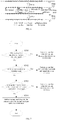
FIG. 8(a) is a schematic diagram of lane line fitting for a separated roadbed,FIG. 8(b) is a schematic diagram of lane line fitting for a conventional ramp,FIG. 8(c) is a schematic diagram of lane line fitting for a conventional main road,FIG. 8(d) is a schematic diagram of lane line fitting for ramp bifurcation, andFIG. 8(e) is a schematic diagram of lane line fitting for departure from a high-speed lane. As shown inFIGS. 8(a)-8(c) , the lane line L1 on one side of the direction of the driving coordinate system is selected as the lane line offset reference for offsetting to obtain other lane lines, and a decision-making lane changing signal, such as changing the lane to the left, is received, and the lane line L1 is also used as the lane line offset reference for offsetting to obtain other lane lines. As shown inFIGS. 8(d)-8(e) , the lane line R1 on one side of the direction of the driving coordinate system is selected as the lane line offset reference for offsetting to obtain other lane lines, and the vehicle can only change the lane to the right, and the lane line R1 is also used as the lane line offset reference for offsetting to obtain other lane lines. - 2) In the case that the actual road working condition is main road narrowing, the road width unchanged side is selected to determine the lane line offset reference.
FIG. 9 is a schematic diagram of lane line fitting for main road narrowing. As shown inFIG. 9 , the navigation information prompts that the main road is narrowing on the right and the width on the left side remains unchanged, then the lane line L1 on the left side is used as the lane line offset reference for offsetting to obtain other lane lines. - 3) In the case that the actual road working condition is ramp merging or ramp-main road joining, the lane continuous side and/or the reference side of the driving coordinate system are/is selected to determine the lane line offset reference.
-
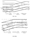
FIG. 10 (a) is a schematic diagram of lane line fitting for ramp merging, andFIG. 10 (b) is a schematic diagram of lane line fitting for ramp-main road joining. As shown inFIG. 10(a) , the lane line R1 on one side of the direction of the driving coordinate system is selected as the lane line offset reference for offsetting to obtain other lane lines. Under this road working condition, the number of lanes on the left side of the vehicle is discontinuous (the number of lanes changes), so the lane line R1 of the continuous lane should be used as the lane line offset reference for offsetting to obtain other lane lines. As shown inFIG. 10(b) , the lane line R1 on one side of the direction of the driving coordinate system is first selected as the lane line offset reference for offsetting to obtain other lane lines. After the start point of the acceleration lane is passed, the driving coordinate system should be switched to the leftmost side of the road, so that the lane line L1 on the left side is changed as the lane line offset reference for offsetting to obtain other lane lines. In addition, under the road working condition shown inFIG. 10(b) , before the start point of the acceleration lane is passed, the number of lanes on the left side of the vehicle is discontinuous (the number of lanes changes), so the lane line R1 of the continuous lane should be used as the lane line offset reference for offsetting to obtain other lane lines. Before the start point of the acceleration lane is passed, the number of lanes on the right side is discontinuous (the number of lanes changes), so the lane line L1 of the continuous lane on the left side should be used as the lane line offset reference for offsetting to obtain other lane lines. - Further, the above example of lane line fitting is output by fitting four lane lines of L1, L2, R1 and R2, but some lane lines, such as L2 or R2, may already be outside the road boundary, and such fitting is not valid. Therefore, the lane line fitting method in the embodiment of the present invention can further comprise: completely or partially deleting, by combining the map information, a lane line that is outside the road boundary of the current road or affected by a road obstacle from the plurality of lane lines.
FIG. 11(a) is a schematic diagram of deleting a lane line outside the road boundary of the current road. It can be seen that the fitted L2 does not actually exist, and it should be considered to delete L2.FIG. 11(b) is a schematic diagram of deleting a lane line affected by a road obstacle. It can be seen that part of the fitted L2 is affected by obstacles, and the lane formed by this part of L2 and L1 is actually not passable, so this part of the fitted L2 does not match the actual road plan, and it should be considered to delete this part of unreasonable fitting in L2. - In summary, the lane line fitting method according to the embodiments of the present invention can accurately and quickly determine a lane line offset reference used for lane line fitting, and outputs an effective lane line based on the lane line offset reference, facilitates lane maintaining and other controls, solves the problem that extracted lane lines are numerous and relatively complex in the prior art, can be adapted to different road scenes, and has high processing efficiency of lane line algorithm.
-
FIG. 12 is a structural schematic diagram of a lane line fitting system according to an embodiment of the present invention. The lane line fitting system is based on the same inventive idea as the above-mentioned embodiment of the lane line fitting method. As shown inFIG. 12 , the lane line fitting system comprises: - an information acquisition unit 1, used for acquiring map information for a current position of a vehicle, wherein the map information comprises the number of lanes, a road width and line point information of lane lines on two sides of the vehicle;
- a
reference determination unit 2, electrically connected to the information acquisition unit 1, and used for determining, from among the lane lines on two sides of the vehicle, a lane line on one side, consistent with the direction indicated by at least one of the following, to be a lane line offset reference used for lane line fitting: a lane changing direction side, indicating the side to which the vehicle is expected to perform lane changing in the current road; a reference side of a driving coordinate system, wherein the driving coordinate system takes a road boundary line on one side of the road on which the vehicle is located as a reference, and takes a road guide line direction and a direction following a left-hand rule with the road guide line direction as two axes; a road width unchanged side, indicating the side where the road width does not change in the road ahead of the vehicle; and a lane continuous side, indicating the side where the lane continuity does not change in the current road; and - a lane line fitting unit 3, electrically connected to the information acquisition unit 1 and the
reference determination unit 2, and used for offsetting based on the lane line offset reference to generate a plurality of lane lines of the vehicle, and performing curve fitting on a set of line points on the plurality of generated lane lines to obtain a corresponding lane line equation. - In a preferred embodiment, the information acquisition unit 1 is further used for acquiring a decision-making lane changing signal and/or navigation information for the current position of the vehicle, wherein the decision-making lane changing signal indicates the lane changing direction side of the vehicle, and the navigation information is used for indicating the road width unchanged side.
- In a preferred embodiment, the lane line fitting system further comprises: a
priority setting unit 4, used for setting the priority of determining the lane line offset reference based on the lane changing direction side, the road width unchanged side, the lane continuous side and the reference side of the driving coordinate system. In addition, thereference determination unit 2 is further electrically connected to thepriority setting unit 4, and used for determining the lane line offset reference based on the priority, set by the priority setting unit, of determining the lane line offset reference based on the lane changing direction side, the road width unchanged side, the lane continuous side and the reference side of the driving coordinate system. - In a more preferred embodiment, the lane line fitting system further comprises: a road working
condition determination unit 5, used for determining an actual road working condition of the vehicle according to the map information. - In addition, the
reference determination unit 2 is also electrically connected to the road workingcondition determination unit 5, and used for selecting, according to the actual road working condition, one or more of the lane changing direction side, the road width unchanged side, the lane continuous side and the reference side of the driving coordinate system to determine the lane line offset reference. - The actual road working condition and the selected lane line offset reference can comprise any one of the following: in the case that the actual road working condition is a separated roadbed, a conventional ramp, a conventional main road, or ramp bifurcation, the lane changing direction side and/or the reference side of the driving coordinate system are/is selected to determine the lane line offset reference; in the case that the actual road working condition is main road narrowing or departure from a high-speed lane, the road width unchanged side is selected to determine the lane line offset reference; and in the case that the actual road working condition is ramp merging or ramp-main road joining, the lane continuous side and/or the reference side of the driving coordinate system are/is selected to determine the lane line offset reference.
- In a more preferred embodiment, the lane line fitting system further comprises: a lane
line screening unit 6, electrically connected to the lane line fitting unit 3, and used for completely or partially deleting, by combining the map information, a lane line that is outside the road boundary of the current road or affected by a road obstacle from the plurality of lane lines. - It should be noted that other implementation details and effects of the lane line fitting system in the embodiments of the present invention can refer to the above-mentioned embodiments of the lane line fitting method, which will not be repeated here.
- The above descriptions are only the preferred embodiments of the present invention and are not intended to limit the present invention. Any modification, equivalent replacement, improvement, etc., made within the spirit and principle of the present invention, such as adaptively changing the order of execution of steps and adjusting the connection relationship between functional modules, shall be comprised in the protection scope of the present invention.
- A person skilled in the art can understand that all or part of the steps in the method of the foregoing embodiments can be implemented by a program instructing related hardware. The program is stored in a storage medium, and comprises several instructions for causing a single chip computer, a chip, or a processor to execute all or part of the steps of the method described in each embodiment of the present application. In addition, the aforementioned storage medium comprises various kinds of mediums that may store program codes, such as a U disk, a mobile hard disk, a Read-Only Memory (ROM), a Random Access Memory (RAM), a magnetic disk or an optical disk.
- In addition, any combination of the various embodiments of the present invention can be made therebetween, which, as long as not violating the idea of the embodiments of the present invention, shall likewise be considered as contents disclosed in the embodiments of the present invention.
Claims (13)
- A lane line fitting method, wherein the method comprises:acquiring map information for a current position of a vehicle, wherein the map information comprises a number of lanes, a road width and line point information of lane lines on two sides of the vehicle;determining, from among the lane lines on two sides of the vehicle, a lane line on one side, consistent with the direction indicated by at least one of the following, to be a lane line offset reference used for lane line fitting:a lane changing direction side, indicating the side to which the vehicle is expected to perform lane changing in the current road;a reference side of a driving coordinate system, wherein the driving coordinate system takes a road boundary line on one side of the road on which the vehicle is located as a reference, and takes a road guide line direction and a direction following a left-hand rule with the road guide line direction as two axes;a road width unchanged side, indicating the side where the road width does not change in the road ahead of the vehicle; anda lane continuous side, indicating the side where the lane continuity does not change in the current road; andoffsetting based on the lane line offset reference to generate a plurality of lane lines of the vehicle, and performing curve fitting on a set of line points on the plurality of generated lane lines to obtain a corresponding lane line equation.
- The lane line fitting method according to claim 1, wherein the method further comprises:
acquiring a decision-making lane changing signal and/or navigation information for the current position of the vehicle, wherein the decision-making lane changing signal indicates the lane changing direction side of the vehicle, and the navigation information is used for indicating the road width unchanged side. - The lane line fitting method according to claim 1, wherein the method further comprises:
setting the priority of determining the lane line offset reference based on the lane changing direction side, the road width unchanged side, the lane continuous side and the reference side of the driving coordinate system. - The lane line fitting method according to claim 1, wherein the method further comprises:
determining an actual road working condition of the vehicle according to the map information, and selecting, according to the actual road working condition, one or more of the lane changing direction side, the road width unchanged side, the lane continuous side and the reference side of the driving coordinate system to determine the lane line offset reference. - The lane line fitting method according to claim 4, wherein the actual road working condition and the selected lane line offset reference comprise any one of the following:in the case that the actual road working condition is a separated roadbed, a conventional ramp, a conventional main road, ramp bifurcation or departure from a high-speed lane, the lane changing direction side and/or the reference side of the driving coordinate system are/is selected to determine the lane line offset reference;in the case that the actual road working condition is main road narrowing, the road width unchanged side is selected to determine the lane line offset reference; andin the case that the actual road working condition is ramp merging or ramp-main road joining, the lane continuous side and/or the reference side of the driving coordinate system are/is selected to determine the lane line offset reference.
- The lane line fitting method according to any one of claims 1-5, wherein the method further comprises:
completely or partially deleting, by combining the map information, a lane line that is outside the road boundary of the current road or affected by a road obstacle from the plurality of lane lines. - A machine-readable storage medium, wherein an instruction is stored on the machine-readable storage medium, and the instruction is used for causing a controller to execute the lane line fitting method according to any one of claims 1-6.
- A lane line fitting system, wherein the system comprises:an information acquisition unit, used for acquiring map information for a current position of a vehicle, wherein the map information comprises a number of lanes, a road width and line point information of lane lines on two sides of the vehicle;a reference determination unit, electrically connected to the information acquisition unit, and used for determining, from among the lane lines on two sides of the vehicle, a lane line on one side, consistent with the direction indicated by at least one of the following, to be a lane line offset reference used for lane line fitting: a lane changing direction side, indicating the side to which the vehicle is expected to perform lane changing in the current road; a reference side of a driving coordinate system, wherein the driving coordinate system takes a road boundary line on one side of the road on which the vehicle is located as a reference, and takes a road guide line direction and a direction following a left-hand rule with the road guide line direction as two axes; a road width unchanged side, indicating the side where the road width does not change in the road ahead of the vehicle; and a lane continuous side, indicating the side where the lane continuity does not change in the current road; anda lane line fitting unit, electrically connected to the information acquisition unit and the reference determination unit, and used for offsetting based on the lane line offset reference to generate a plurality of lane lines of the vehicle, and performing curve fitting on a set of line points on the plurality of generated lane lines to obtain a corresponding lane line equation.
- The lane line fitting system according to claim 8, wherein the information acquisition unit is further used for acquiring a decision-making lane changing signal and/or navigation information for the current position of the vehicle, wherein the decision-making lane changing signal indicates the lane changing direction side of the vehicle, and the navigation information is used for indicating the road width unchanged side.
- The lane line fitting system according to claim 8, wherein the system further comprises:a priority setting unit, used for setting the priority of determining the lane line offset reference based on the lane changing direction side, the road width unchanged side, the lane continuous side and the reference side of the driving coordinate system,and, the reference determination unit is further electrically connected to the priority setting unit, and used for determining the lane line offset reference based on the priority, set by the priority setting unit, of determining the lane line offset reference based on the lane changing direction side, the road width unchanged side, the lane continuous side and the reference side of the driving coordinate system.
- The lane line fitting system according to claim 8, wherein the system further comprises:a road working condition determination unit, used for determining an actual road working condition of the vehicle according to the map information,and, the reference determination unit is also electrically connected to the road working condition determination unit, and used for selecting, according to the actual road working condition, one or more of the lane changing direction side, the road width unchanged side, the lane continuous side and the reference side of the driving coordinate system to determine the lane line offset reference.
- The lane line fitting system according to claim 11, wherein the actual road working condition and the selected lane line offset reference comprise any one of the following:in the case that the actual road working condition is a separated roadbed, a conventional ramp, a conventional main road, ramp bifurcation or departure from a high-speed lane, the lane changing direction side and/or the reference side of the driving coordinate system are/is selected to determine the lane line offset reference;in the case that the actual road working condition is main road narrowing, the road width unchanged side is selected to determine the lane line offset reference; andin the case that the actual road working condition is ramp merging or ramp-main road joining, the lane continuous side and/or the reference side of the driving coordinate system are/is selected to determine the lane line offset reference.
- The lane line fitting system according to any one of claims 8-12, wherein the system further comprises:
a lane line screening unit, electrically connected to the lane line fitting unit, and used for completely or partially deleting, by combining the map information, a lane line that is outside the road boundary of the current road or affected by a road obstacle from the plurality of lane lines.
Applications Claiming Priority (2)
| Application Number | Priority Date | Filing Date | Title |
|---|---|---|---|
| CN201811154050.XA CN110361021B (en) | 2018-09-30 | 2018-09-30 | Lane line fitting method and system |
| PCT/CN2019/108403 WO2020063817A1 (en) | 2018-09-30 | 2019-09-27 | Traffic lane line fitting method and system |
Publications (2)
| Publication Number | Publication Date |
|---|---|
| EP3859280A1 true EP3859280A1 (en) | 2021-08-04 |
| EP3859280A4 EP3859280A4 (en) | 2021-11-17 |
Family
ID=68214753
Family Applications (1)
| Application Number | Title | Priority Date | Filing Date |
|---|---|---|---|
| EP19866854.3A Pending EP3859280A4 (en) | 2018-09-30 | 2019-09-27 | Taxiway line adjustment method and system |
Country Status (6)
| Country | Link |
|---|---|
| US (1) | US12007243B2 (en) |
| EP (1) | EP3859280A4 (en) |
| JP (1) | JP7185775B2 (en) |
| KR (1) | KR102512207B1 (en) |
| CN (1) | CN110361021B (en) |
| WO (1) | WO2020063817A1 (en) |
Families Citing this family (22)
| Publication number | Priority date | Publication date | Assignee | Title |
|---|---|---|---|---|
| US11518384B2 (en) * | 2018-12-07 | 2022-12-06 | Thinkware Corporation | Method for displaying lane information and apparatus for executing the method |
| CN113022573B (en) | 2019-12-06 | 2022-11-04 | 华为技术有限公司 | Road structure detection method and device |
| CN113327456A (en) * | 2020-02-28 | 2021-08-31 | 华为技术有限公司 | Lane structure detection method and device |
| CN113409583B (en) * | 2020-03-16 | 2022-10-18 | 华为技术有限公司 | Lane line information determination method and device |
| CN113494917B (en) * | 2020-04-07 | 2024-11-15 | 上汽通用汽车有限公司 | Map construction method and system, method for formulating navigation strategy and storage medium |
| CN111652952B (en) * | 2020-06-05 | 2022-03-18 | 腾讯科技(深圳)有限公司 | Lane line generation method, lane line generation device, computer device, and storage medium |
| KR20220029859A (en) * | 2020-09-01 | 2022-03-10 | 현대자동차주식회사 | Apparatus and method for controlling driving of vehicle |
| FR3113879A1 (en) * | 2020-09-10 | 2022-03-11 | Psa Automobiles Sa | Method and device for partitioning a widening zone of a traffic lane delimited by two edges. |
| US11756312B2 (en) * | 2020-09-17 | 2023-09-12 | GM Global Technology Operations LLC | Orientation-agnostic lane tracking in a vehicle |
| US12024170B2 (en) * | 2020-12-14 | 2024-07-02 | Zoox, Inc. | Lane change gap finder |
| KR20220094831A (en) * | 2020-12-29 | 2022-07-06 | 현대자동차주식회사 | A lane-link and road shape information based driving system and driving method |
| CN113177993B (en) * | 2021-03-22 | 2024-03-01 | 中国人民解放军32801部队 | A method and system for generating high-precision maps in a simulation environment |
| CN113551664B (en) * | 2021-08-02 | 2022-02-25 | 湖北亿咖通科技有限公司 | Map construction method and device, electronic equipment and storage medium |
| CN114092909B (en) * | 2021-11-22 | 2025-04-01 | 中国第一汽车股份有限公司 | Lane line extraction method, device, vehicle and storage medium |
| CN114399589B (en) * | 2021-12-20 | 2022-11-11 | 禾多科技(北京)有限公司 | Three-dimensional lane line generation method and device, electronic device and computer readable medium |
| CN114419885A (en) * | 2022-01-14 | 2022-04-29 | 重庆长安汽车股份有限公司 | Vehicle violation snapshot method and system based on high-precision positioning and vehicle-mounted sensing capability |
| CN115014326B (en) * | 2022-06-01 | 2026-01-23 | 北京经纬恒润科技股份有限公司 | Road map construction method and device |
| CN115056782B (en) * | 2022-07-14 | 2024-08-13 | 东风商用车有限公司 | Intelligent driving lane change track generation method, system and computer storage medium |
| CN116101292B (en) * | 2022-09-08 | 2023-10-27 | 广州汽车集团股份有限公司 | Method and system for obtaining longitudinal distance between vehicles on road and vehicle |
| CN115661291B (en) * | 2022-10-24 | 2026-03-17 | 智道网联科技(北京)有限公司 | Methods, equipment, and computer-readable storage media for generating green belts in electronic maps |
| CN115727834B (en) * | 2022-11-16 | 2024-08-09 | 新石器慧通(北京)科技有限公司 | Method for reverse inspection processing of boundary line, map making method, device and medium |
| CN115900734A (en) * | 2022-11-30 | 2023-04-04 | 毫末智行科技有限公司 | Method, device, vehicle, and storage medium for generating guidelines at expressway intersections |
Family Cites Families (29)
| Publication number | Priority date | Publication date | Assignee | Title |
|---|---|---|---|---|
| JP3427815B2 (en) * | 2000-03-30 | 2003-07-22 | 株式会社デンソー | Method and apparatus for selecting preceding vehicle, recording medium |
| US8676492B2 (en) * | 2006-01-19 | 2014-03-18 | GM Global Technology Operations LLC | Map-aided vision-based lane sensing |
| JP2008309529A (en) * | 2007-06-12 | 2008-12-25 | Panasonic Corp | NAVIGATION DEVICE, NAVIGATION METHOD, AND NAVIGATION PROGRAM |
| JP5124875B2 (en) | 2008-03-12 | 2013-01-23 | 本田技研工業株式会社 | Vehicle travel support device, vehicle, vehicle travel support program |
| JP2009237901A (en) * | 2008-03-27 | 2009-10-15 | Zenrin Co Ltd | Method of creating road marker map |
| US8311283B2 (en) | 2008-07-06 | 2012-11-13 | Automotive Research&Testing Center | Method for detecting lane departure and apparatus thereof |
| WO2010004689A1 (en) | 2008-07-07 | 2010-01-14 | 三菱電機株式会社 | Vehicle traveling environment detection device |
| KR101163446B1 (en) * | 2009-03-18 | 2012-07-18 | 기아자동차주식회사 | A lane departure warning system using a virtual lane and a system according to the same |
| JP2011013039A (en) * | 2009-06-30 | 2011-01-20 | Clarion Co Ltd | Lane determination device and navigation system |
| CN102667888B (en) * | 2009-11-27 | 2014-12-31 | 丰田自动车株式会社 | Drive assistance device and drive assistance method |
| US8452535B2 (en) * | 2010-12-13 | 2013-05-28 | GM Global Technology Operations LLC | Systems and methods for precise sub-lane vehicle positioning |
| KR101362324B1 (en) * | 2012-06-05 | 2014-02-24 | 현대모비스 주식회사 | System and Method for Lane Departure Warning |
| CN103832433B (en) * | 2012-11-21 | 2016-08-10 | 中国科学院沈阳计算技术研究所有限公司 | Deviation and front truck anti-collision alarm system and its implementation |
| JP6128584B2 (en) | 2013-01-16 | 2017-05-17 | 株式会社Soken | Travel route generator |
| KR101502511B1 (en) * | 2013-11-28 | 2015-03-13 | 현대모비스 주식회사 | Apparatus and method for generating virtual lane, and system for controlling lane keeping of vehicle with the said apparatus |
| KR102255432B1 (en) * | 2014-06-17 | 2021-05-24 | 팅크웨어(주) | Electronic apparatus and control method thereof |
| JP2017001046A (en) | 2015-06-05 | 2017-01-05 | 株式会社Ihi | Laser cutting system |
| DE112015006622B4 (en) * | 2015-06-15 | 2025-02-06 | Mitsubishi Electric Corporation | lane determination device and lane determination method |
| JP6515704B2 (en) * | 2015-06-25 | 2019-05-22 | 富士通株式会社 | Lane detection device and lane detection method |
| JP6558120B2 (en) | 2015-07-29 | 2019-08-14 | いすゞ自動車株式会社 | Direction indicator control device |
| CN105260699B (en) * | 2015-09-10 | 2018-06-26 | 百度在线网络技术(北京)有限公司 | A kind of processing method and processing device of lane line data |
| CN105588576B (en) * | 2015-12-15 | 2019-02-05 | 招商局重庆交通科研设计院有限公司 | A lane-level navigation method and system |
| CN105528588B (en) * | 2015-12-31 | 2019-04-23 | 百度在线网络技术(北京)有限公司 | A kind of Lane detection method and device |
| CN106096525B (en) * | 2016-06-06 | 2019-07-19 | 重庆邮电大学 | A compound lane recognition system and method |
| KR101866075B1 (en) * | 2016-10-20 | 2018-06-08 | 현대자동차주식회사 | Apparatus and method for estmating lane |
| CN106525056A (en) * | 2016-11-04 | 2017-03-22 | 杭州奥腾电子股份有限公司 | Method for lane line detection by gyro sensor |
| IT201600132670A1 (en) * | 2016-12-30 | 2018-06-30 | St Microelectronics Srl | PROCEDURE FOR GENERATING A WARNING FOR ABANDONES IN A VEHICLE, ITS SYSTEM AND IT PRODUCT |
| CN107392103B (en) * | 2017-06-21 | 2020-06-26 | 海信集团有限公司 | Method and device for detecting road lane line and electronic equipment |
| KR102374919B1 (en) * | 2017-10-16 | 2022-03-16 | 주식회사 만도모빌리티솔루션즈 | Device And Method of Automatic Driving Support |
-
2018
- 2018-09-30 CN CN201811154050.XA patent/CN110361021B/en active Active
-
2019
- 2019-09-27 KR KR1020217013026A patent/KR102512207B1/en active Active
- 2019-09-27 JP JP2021517850A patent/JP7185775B2/en active Active
- 2019-09-27 EP EP19866854.3A patent/EP3859280A4/en active Pending
- 2019-09-27 US US17/281,561 patent/US12007243B2/en active Active
- 2019-09-27 WO PCT/CN2019/108403 patent/WO2020063817A1/en not_active Ceased
Also Published As
| Publication number | Publication date |
|---|---|
| JP2022501612A (en) | 2022-01-06 |
| WO2020063817A1 (en) | 2020-04-02 |
| CN110361021B (en) | 2021-06-22 |
| CN110361021A (en) | 2019-10-22 |
| KR102512207B1 (en) | 2023-03-21 |
| EP3859280A4 (en) | 2021-11-17 |
| US20210389153A1 (en) | 2021-12-16 |
| KR20210064369A (en) | 2021-06-02 |
| US12007243B2 (en) | 2024-06-11 |
| JP7185775B2 (en) | 2022-12-07 |
Similar Documents
| Publication | Publication Date | Title |
|---|---|---|
| EP3859280A1 (en) | Traffic lane line fitting method and system | |
| CN113460086B (en) | Control system, method, vehicle and storage medium for automatically driving to enter ramp | |
| EP3859273A1 (en) | Method for constructing driving coordinate system, and application thereof | |
| US12135552B2 (en) | Road feature point extraction method and system | |
| CN111653113B (en) | Method, device, terminal and storage medium for determining local path of vehicle | |
| JP7422661B2 (en) | Travel trajectory correction method, travel control method, and travel trajectory correction device | |
| US11449058B2 (en) | Traveling track determination processing and automated drive device | |
| KR102534412B1 (en) | Method and apparatus for extracting feature points of environmental targets | |
| US12214803B2 (en) | Travel assistance method and travel assistance device | |
| US20230294700A1 (en) | Traveling route generation apparatus and traveling route generation method | |
| CN115042820A (en) | Automatic driving vehicle control method, device, device and storage medium | |
| EP4201769A1 (en) | Vehicle control device, vehicle control method, and non-transitory storage medium | |
| KR20190047199A (en) | Apparatus for providing a map information for deciding driving situation of vehicle, system having the same and method thereof | |
| CN114987556A (en) | Automatic driving vehicle control method, device, device and storage medium | |
| JP6838769B2 (en) | Surrounding environment recognition device, display control device | |
| CN110962856B (en) | Method and device for determining area of vehicle where environmental target is located | |
| CN110967699B (en) | Method and device for determining area of vehicle where environmental target is located | |
| JP2023184097A (en) | Driving support system, driving support method, and driving support program | |
| CN115615450A (en) | A planning method, system and medium for reducing the dependence on positioning and high-precision maps in the sub-section area of structured roads | |
| CN119953403B (en) | Prediction trajectory correction method, device, equipment and medium | |
| RU2777141C1 (en) | Traffic aid method and traffic aid device | |
| CN121019574A (en) | Vehicle passing control methods, electronic equipment, vehicles, media and products |
Legal Events
| Date | Code | Title | Description |
|---|---|---|---|
| STAA | Information on the status of an ep patent application or granted ep patent |
Free format text: STATUS: THE INTERNATIONAL PUBLICATION HAS BEEN MADE |
|
| PUAI | Public reference made under article 153(3) epc to a published international application that has entered the european phase |
Free format text: ORIGINAL CODE: 0009012 |
|
| STAA | Information on the status of an ep patent application or granted ep patent |
Free format text: STATUS: REQUEST FOR EXAMINATION WAS MADE |
|
| 17P | Request for examination filed |
Effective date: 20210330 |
|
| AK | Designated contracting states |
Kind code of ref document: A1 Designated state(s): AL AT BE BG CH CY CZ DE DK EE ES FI FR GB GR HR HU IE IS IT LI LT LU LV MC MK MT NL NO PL PT RO RS SE SI SK SM TR |
|
| STAA | Information on the status of an ep patent application or granted ep patent |
Free format text: STATUS: EXAMINATION IS IN PROGRESS |
|
| A4 | Supplementary search report drawn up and despatched |
Effective date: 20211014 |
|
| RIC1 | Information provided on ipc code assigned before grant |
Ipc: B60W 30/12 20200101ALI20211011BHEP Ipc: G01C 21/34 20060101AFI20211011BHEP |
|
| 17Q | First examination report despatched |
Effective date: 20211026 |
|
| DAV | Request for validation of the european patent (deleted) | ||
| DAX | Request for extension of the european patent (deleted) | ||
| GRAP | Despatch of communication of intention to grant a patent |
Free format text: ORIGINAL CODE: EPIDOSNIGR1 |
|
| STAA | Information on the status of an ep patent application or granted ep patent |
Free format text: STATUS: GRANT OF PATENT IS INTENDED |
|
| INTG | Intention to grant announced |
Effective date: 20260112 |
|
| P01 | Opt-out of the competence of the unified patent court (upc) registered |
Free format text: CASE NUMBER: UPC_APP_0007238_3859280/2026 Effective date: 20260226 |
|
| GRAS | Grant fee paid |
Free format text: ORIGINAL CODE: EPIDOSNIGR3 |
|
| GRAA | (expected) grant |
Free format text: ORIGINAL CODE: 0009210 |
|
| STAA | Information on the status of an ep patent application or granted ep patent |
Free format text: STATUS: THE PATENT HAS BEEN GRANTED |