EP3859259A1 - Evaporator with grooved channels - Google Patents
Evaporator with grooved channels Download PDFInfo
- Publication number
- EP3859259A1 EP3859259A1 EP21154911.8A EP21154911A EP3859259A1 EP 3859259 A1 EP3859259 A1 EP 3859259A1 EP 21154911 A EP21154911 A EP 21154911A EP 3859259 A1 EP3859259 A1 EP 3859259A1
- Authority
- EP
- European Patent Office
- Prior art keywords
- channels
- multiple inflow
- inflow channels
- orifice
- center plug
- Prior art date
- Legal status (The legal status is an assumption and is not a legal conclusion. Google has not performed a legal analysis and makes no representation as to the accuracy of the status listed.)
- Granted
Links
Images


Classifications
-
- F—MECHANICAL ENGINEERING; LIGHTING; HEATING; WEAPONS; BLASTING
- F28—HEAT EXCHANGE IN GENERAL
- F28F—DETAILS OF HEAT-EXCHANGE AND HEAT-TRANSFER APPARATUS, OF GENERAL APPLICATION
- F28F1/00—Tubular elements; Assemblies of tubular elements
- F28F1/02—Tubular elements of cross-section which is non-circular
- F28F1/06—Tubular elements of cross-section which is non-circular crimped or corrugated in cross-section
-
- F—MECHANICAL ENGINEERING; LIGHTING; HEATING; WEAPONS; BLASTING
- F28—HEAT EXCHANGE IN GENERAL
- F28D—HEAT-EXCHANGE APPARATUS, NOT PROVIDED FOR IN ANOTHER SUBCLASS, IN WHICH THE HEAT-EXCHANGE MEDIA DO NOT COME INTO DIRECT CONTACT
- F28D1/00—Heat-exchange apparatus having stationary conduit assemblies for one heat-exchange medium only, the media being in contact with different sides of the conduit wall, in which the other heat-exchange medium is a large body of fluid, e.g. domestic or motor car radiators
- F28D1/02—Heat-exchange apparatus having stationary conduit assemblies for one heat-exchange medium only, the media being in contact with different sides of the conduit wall, in which the other heat-exchange medium is a large body of fluid, e.g. domestic or motor car radiators with heat-exchange conduits immersed in the body of fluid
- F28D1/0246—Heat-exchange apparatus having stationary conduit assemblies for one heat-exchange medium only, the media being in contact with different sides of the conduit wall, in which the other heat-exchange medium is a large body of fluid, e.g. domestic or motor car radiators with heat-exchange conduits immersed in the body of fluid heat-exchange elements having several adjacent conduits forming a whole, e.g. blocks
-
- F—MECHANICAL ENGINEERING; LIGHTING; HEATING; WEAPONS; BLASTING
- F28—HEAT EXCHANGE IN GENERAL
- F28D—HEAT-EXCHANGE APPARATUS, NOT PROVIDED FOR IN ANOTHER SUBCLASS, IN WHICH THE HEAT-EXCHANGE MEDIA DO NOT COME INTO DIRECT CONTACT
- F28D15/00—Heat-exchange apparatus with the intermediate heat-transfer medium in closed tubes passing into or through the conduit walls ; Heat-exchange apparatus employing intermediate heat-transfer medium or bodies
- F28D15/02—Heat-exchange apparatus with the intermediate heat-transfer medium in closed tubes passing into or through the conduit walls ; Heat-exchange apparatus employing intermediate heat-transfer medium or bodies in which the medium condenses and evaporates, e.g. heat pipes
- F28D15/0233—Heat-exchange apparatus with the intermediate heat-transfer medium in closed tubes passing into or through the conduit walls ; Heat-exchange apparatus employing intermediate heat-transfer medium or bodies in which the medium condenses and evaporates, e.g. heat pipes the conduits having a particular shape, e.g. non-circular cross-section, annular
-
- F—MECHANICAL ENGINEERING; LIGHTING; HEATING; WEAPONS; BLASTING
- F28—HEAT EXCHANGE IN GENERAL
- F28F—DETAILS OF HEAT-EXCHANGE AND HEAT-TRANSFER APPARATUS, OF GENERAL APPLICATION
- F28F1/00—Tubular elements; Assemblies of tubular elements
- F28F1/02—Tubular elements of cross-section which is non-circular
- F28F1/022—Tubular elements of cross-section which is non-circular with multiple channels
-
- F—MECHANICAL ENGINEERING; LIGHTING; HEATING; WEAPONS; BLASTING
- F28—HEAT EXCHANGE IN GENERAL
- F28F—DETAILS OF HEAT-EXCHANGE AND HEAT-TRANSFER APPARATUS, OF GENERAL APPLICATION
- F28F1/00—Tubular elements; Assemblies of tubular elements
- F28F1/10—Tubular elements and assemblies thereof with means for increasing heat-transfer area, e.g. with fins, with projections, with recesses
- F28F1/40—Tubular elements and assemblies thereof with means for increasing heat-transfer area, e.g. with fins, with projections, with recesses the means being only inside the tubular element
-
- F—MECHANICAL ENGINEERING; LIGHTING; HEATING; WEAPONS; BLASTING
- F28—HEAT EXCHANGE IN GENERAL
- F28F—DETAILS OF HEAT-EXCHANGE AND HEAT-TRANSFER APPARATUS, OF GENERAL APPLICATION
- F28F9/00—Casings; Header boxes; Auxiliary supports for elements; Auxiliary members within casings
- F28F9/02—Header boxes; End plates
- F28F9/026—Header boxes; End plates with static flow control means, e.g. with means for uniformly distributing heat exchange media into conduits
- F28F9/0282—Header boxes; End plates with static flow control means, e.g. with means for uniformly distributing heat exchange media into conduits by varying the geometry of conduit ends, e.g. by using inserts or attachments for modifying the pattern of flow at the conduit inlet or outlet
-
- B—PERFORMING OPERATIONS; TRANSPORTING
- B64—AIRCRAFT; AVIATION; COSMONAUTICS
- B64G—COSMONAUTICS; VEHICLES OR EQUIPMENT THEREFOR
- B64G1/00—Cosmonautic vehicles
- B64G1/22—Parts of, or equipment specially adapted for fitting in or to, cosmonautic vehicles
- B64G1/46—Arrangements or adaptations of devices for control of environment or living conditions
- B64G1/50—Arrangements or adaptations of devices for control of environment or living conditions for temperature control
- B64G1/506—Heat pipes
-
- F—MECHANICAL ENGINEERING; LIGHTING; HEATING; WEAPONS; BLASTING
- F28—HEAT EXCHANGE IN GENERAL
- F28D—HEAT-EXCHANGE APPARATUS, NOT PROVIDED FOR IN ANOTHER SUBCLASS, IN WHICH THE HEAT-EXCHANGE MEDIA DO NOT COME INTO DIRECT CONTACT
- F28D21/00—Heat-exchange apparatus not covered by any of the groups F28D1/00 - F28D20/00
- F28D2021/0019—Other heat exchangers for particular applications; Heat exchange systems not otherwise provided for
- F28D2021/0061—Other heat exchangers for particular applications; Heat exchange systems not otherwise provided for for phase-change applications
- F28D2021/0064—Vaporizers, e.g. evaporators
-
- F—MECHANICAL ENGINEERING; LIGHTING; HEATING; WEAPONS; BLASTING
- F28—HEAT EXCHANGE IN GENERAL
- F28D—HEAT-EXCHANGE APPARATUS, NOT PROVIDED FOR IN ANOTHER SUBCLASS, IN WHICH THE HEAT-EXCHANGE MEDIA DO NOT COME INTO DIRECT CONTACT
- F28D21/00—Heat-exchange apparatus not covered by any of the groups F28D1/00 - F28D20/00
- F28D2021/0019—Other heat exchangers for particular applications; Heat exchange systems not otherwise provided for
- F28D2021/0068—Other heat exchangers for particular applications; Heat exchange systems not otherwise provided for for refrigerant cycles
- F28D2021/0071—Evaporators
Definitions
- the following description relates to evaporators and, more particularly, to an evaporator with grooved channels for terrestrial and microgravity environments.
- Evaporators utilize latent heat of a fluid to absorb waste heat from a heat source. As such, in order to operate efficiently, an evaporating surface of an evaporator should be covered by a layer of a liquid phase of a working fluid as much as possible during operational conditions.
- liquid phase of a working fluid tends to accumulate and move in the direction of gravity in a terrestrial environment.
- a microgravity environment liquid distribution is randomized and tends to move freely if undisturbed. Therefore, in each of these terrestrial and microgravity environment cases, it is often critical to replenish evaporating surfaces of evaporators with liquid.
- an orifice insert includes a center plug and a ring feature.
- the center plug has first and second ends and an exterior surface extending between the first and second ends.
- the exterior surface defines multiple inflow channels that extend from the first end toward the second end and terminate at termination points midway between the first and second ends.
- the ring feature is disposed about the center plug and the multiple inflow channels to define, with the center plug, a plenum with which the termination points of the multiple inflow channels are fluidly communicative.
- the exterior surface has a curved plane at each of the multiple inflow channels and each of the multiple inflow channels has a u-shape cross-section directed inwardly from the curved plane.
- the termination points of each of the multiple inflow channels are scalloped.
- the plenum extends circumferentially about the center plug and the multiple inflow channels.
- the ring feature includes an axial face adjacent to the center plug and the multiple inflow channels and a radial face at a distal edge of the axial face to face the center plug and the multiple inflow channels.
- an evaporator includes an inlet header, a body defining channels, each of which includes grooves circumferentially arranged about an open central region to extend radially outwardly from the open central region and orifice inserts respectively interposable between the inlet header and a corresponding channel to respectively encourage fluid flow from the inlet header to the corresponding channel to flow into the grooves.
- the inlet header includes a header body defining a cavity, apertures for fluid communication and an external groove and the orifice inserts are respectively insertable into corresponding apertures and are seatable in the external groove.
- the orifice inserts each include a center plug and a ring feature.
- the center plug has first and second ends and an exterior surface extending between the first and second ends.
- the exterior surface defines multiple inflow channels that extend from the first end toward the second end and terminate at termination points midway between the first and second ends.
- the ring feature is disposed about the center plug and the multiple inflow channels to define, with the center plug, a plenum with which the termination points of the multiple inflow channels are fluidly communicative.
- the exterior surface has a curved plane at each of the multiple inflow channels and each of the multiple inflow channels has a u-shape cross-section directed inwardly from the curved plane.
- the termination points of each of the multiple inflow channels are scalloped.
- the plenum extends circumferentially about the center plug and the multiple inflow channels.
- the ring feature includes an axial face adjacent to the center plug and the multiple inflow channels and a radial face at a distal edge of the axial face to face the center plug and the multiple inflow channels.
- an evaporator includes an inlet header, a body defining channels and orifice inserts respectively interposable between the inlet header and corresponding channels.
- Each channel includes grooves respectively delimited by first and second interior facing sidewalls of the body which form a base and an apex with an apex angle opposite the base and defined such that, for a fluid flow moving through one of the channels in a microgravity environment a portion of the fluid flow in a liquid phase within a groove of the channel will move in the groove from the base to the apex and a portion of the fluid flow in a vapor phase within a groove of the channel will move in the groove from the apex to the base.
- Each orifice insert is configured to encourage fluid flow from the inlet header to the corresponding channel to flow into the grooves.
- the apex angle is 2 ⁇ , where ⁇ is less than 90° minus a solid-liquid contact angle.
- the inlet header includes a header body defining a cavity, apertures for fluid communication and an external groove and the orifice inserts are respectively insertable into corresponding apertures and seatable in the external groove.
- the orifice inserts each include a center plug and a ring feature.
- the center plug has first and second ends and an exterior surface extending between the first and second ends.
- the exterior surface defines multiple inflow channels that extend from the first end toward the second end and terminate at termination points midway between the first and second ends.
- the ring feature is disposed about the center plug and the multiple inflow channels to define, with the center plug, a plenum with which the termination points of the multiple inflow channels are fluidly communicative.
- the exterior surface has a curved plane at each of the multiple inflow channels and each of the multiple inflow channels has a u-shape cross-section directed inwardly from the curved plane.
- the termination points of each of the multiple inflow channels are scalloped.
- the plenum extends circumferentially about the center plug and the multiple inflow channels.
- the ring feature includes an axial face adjacent to the center plug and the multiple inflow channels and a radial face at a distal edge of the axial face to face the center plug and the multiple inflow channels.
- Movement of liquid in a microgravity environment is mainly dictated by a surface tension of the liquid, characteristics of a surface the liquid is intended to be in contact with and external disturbances applied to the system.
- the liquid will tend to pool and flow in the direction of gravity.
- liquid can be replenished into the groove and vapor can be expelled out of the groove at similar rates which is useful in the replenishment of liquid on an evaporating surface of an evaporator.
- a groove geometry in which liquid can be replenished into the groove and vapor can be expelled out of the groove at similar rates in integrated into an evaporator design.
- the evaporator design is therefore suitable for both terrestrial and microgravity environments.
- Multiple flow distributors placed at the inflow header provide a desired back pressure which ensures uniform flow distribution among multiple parallel flow channels in the evaporator.
- the flow channels in the flow distributor guide the liquid directly to the grooves.
- the combination of flow distributor and grooved channels ensure an efficient evaporator operation.
- an evaporator element 101 includes a first header (hereinafter referred to as an "inlet header") 110, a second header (hereinafter referred to as an "outlet header") 120 and a body 130.
- the body 130 is formed to define channels 140 that may be arranged in a linear formation 141 across a width W of the body 130.
- Each of the channels 140 can have a substantially same shape as the others and includes grooves 142 that are circumferentially arrayed to extend radially outwardly from an open central region 143.
- Each of the grooves 142 has a same shape as the others and is immediately adjacent to neighboring grooves 142.
- each of the grooves 142 is delimited by first and second interior facing sidewalls 144 of the body 130.
- the first and second interior facing sidewalls 144 are tapered toward each other to form a base B and an apex A.
- the apex A is opposite the base B and has an apex angle 2 ⁇ where ⁇ is less than 90° minus a solid-liquid contact angle.
- the apex angle 2 ⁇ is defined such that, for a fluid flow moving through one of the channels 140 in a microgravity environment where a portion of the fluid flow is in a liquid phase and another portion of the fluid flow is in a vapor phase, the portion of the fluid flow in the liquid phase within a particular groove 142 of the channel 140 will move in the particular groove 142 from the base B to the apex A and the portion of the fluid flow in the vapor phase within the particular groove 142 will move in the particular groove 142 from the apex A to the base B.
- FIG. 4 an operation of the channels 140 and the grooves 142 in a microgravity environment is illustrated.
- the liquid moves in the direction from the base B and to the apex A.
- the vapor is expelled from the apex A toward the base B and to the open central region 143.
- FIG. 5 an operation of the channels 140 and the grooves 142 in a gravity field is illustrated. As shown in FIG. 5 , due to the influence of gravity, the liquid is mostly accumulated at the bottom portion of the channels 140. Nevertheless, since heat applied to the body 130 can be conducted to the liquid, vaporization of the liquid is still possible.
- an orifice insert 601 is provided and includes a center plug 610 and a ring feature 620.
- the center plug 610 has a first end 611, a second end 612 opposite the first end 611 and an exterior surface 613 that extends between the first and second ends 611 and 612.
- the exterior surface 613 has a curved plane P and is formed to define multiple inflow channels 630 that extend from the first end 611 toward the second end 612 and that terminate at termination points 631 defined midway between the first and second ends 611 and 612.
- Each of the multiple inflow channels 630 has a u-shaped cross-section 632 that is directed inwardly from the curved plane P.
- the ring feature 620 is disposed about the center plug 610 and the multiple inflow channels 630 and includes an axial face 621 and a radial face 622.
- the axial face 621 is adjacent to the center plug 610 and the multiple inflow channels 630.
- the radial face 622 is disposed at a distal edge of the axial face 621 and is oriented to face radially inwardly toward the center plug 610 and the multiple inflow channels 630.
- the ring feature 620 is thus disposed to define, with the center plug 610, a plenum 640 with which the termination points 631 of the multiple inflow channels 630 are fluidly communicative.
- the plenum 640 extends circumferentially about the center plug 610 and the multiple inflow channels 630.
- the multiple inflow channels 630 thus extend beneath the ring feature 620 in a radial dimension.
- the termination points 631 are axially aligned with the plenum 640 and can be scalloped or otherwise configured to direct fluid flow moving along the multiple inflow channels 630 radially outwardly and into the plenum 640.
- the multiple inflow channels 630 are designed and configured to create a desired back pressure to achieve proper flow distribution among the channels 140 in the body 130 (see FIGS. 1 and 2 ). Fluid moving along one of the multiple inflow channels 630 flows from the first end 611 and toward the second end 612. The fluid passes beneath the ring feature 620 in a radial dimension and interacts with the corresponding termination point 631. This interaction causes the fluid to enter the plenum 640 and to flow in a circumferential direction.
- orifice inserts 601 are respectively interposable between the inlet header 110 and a corresponding channel 140 in the body 130 of the evaporator element 101 (se FIG. 1 ).
- the inlet header 110 includes a header body 901 that is formed to define a central cavity 910 (see FIG. 8 ), apertures 920 for fluid communication between the central cavity 910 and the channels 140 and an external groove 930.
- the orifice inserts 601 are respectively insertable into corresponding ones of the apertures 920 and are seatable in the external groove 930 to respectively register with corresponding ones of the channels 140.
- the orifice insert 601 is disposed and configured to encourage fluid of the fluid flow from the inlet header 110 to the corresponding channel 140 to flow into the grooves 142 of the corresponding channel 140.
- liquid entering the inlet header 110 is distributed to each of the apertures 1120 by the central cavity 1110. Once the liquid enters an aperture 1120, the liquid is forced into the multiple inflow channels 630 and flows along the multiple inflow channels 630 to the termination points 631.
- the termination points 631 redirect the liquid into the plenum 640 whereupon the liquid is directed into the grooves 142 of the channels 140.
Landscapes
- Engineering & Computer Science (AREA)
- Physics & Mathematics (AREA)
- Thermal Sciences (AREA)
- Mechanical Engineering (AREA)
- General Engineering & Computer Science (AREA)
- Geometry (AREA)
- Life Sciences & Earth Sciences (AREA)
- Sustainable Development (AREA)
- Heat-Exchange Devices With Radiators And Conduit Assemblies (AREA)
- Vaporization, Distillation, Condensation, Sublimation, And Cold Traps (AREA)
Abstract
Description
- The following description relates to evaporators and, more particularly, to an evaporator with grooved channels for terrestrial and microgravity environments.
- Evaporators utilize latent heat of a fluid to absorb waste heat from a heat source. As such, in order to operate efficiently, an evaporating surface of an evaporator should be covered by a layer of a liquid phase of a working fluid as much as possible during operational conditions.
- The liquid phase of a working fluid (i.e., liquid) tends to accumulate and move in the direction of gravity in a terrestrial environment. In a microgravity environment, liquid distribution is randomized and tends to move freely if undisturbed. Therefore, in each of these terrestrial and microgravity environment cases, it is often critical to replenish evaporating surfaces of evaporators with liquid.
- According to an aspect of the disclosure, an orifice insert is provided and includes a center plug and a ring feature. The center plug has first and second ends and an exterior surface extending between the first and second ends. The exterior surface defines multiple inflow channels that extend from the first end toward the second end and terminate at termination points midway between the first and second ends. The ring feature is disposed about the center plug and the multiple inflow channels to define, with the center plug, a plenum with which the termination points of the multiple inflow channels are fluidly communicative.
- In accordance with additional or alternative embodiments, the exterior surface has a curved plane at each of the multiple inflow channels and each of the multiple inflow channels has a u-shape cross-section directed inwardly from the curved plane.
- In accordance with additional or alternative embodiments, the termination points of each of the multiple inflow channels are scalloped.
- In accordance with additional or alternative embodiments, the plenum extends circumferentially about the center plug and the multiple inflow channels.
- In accordance with additional or alternative embodiments, the ring feature includes an axial face adjacent to the center plug and the multiple inflow channels and a radial face at a distal edge of the axial face to face the center plug and the multiple inflow channels.
- According to an aspect of the disclosure, an evaporator is provided and includes an inlet header, a body defining channels, each of which includes grooves circumferentially arranged about an open central region to extend radially outwardly from the open central region and orifice inserts respectively interposable between the inlet header and a corresponding channel to respectively encourage fluid flow from the inlet header to the corresponding channel to flow into the grooves.
- In accordance with additional or alternative embodiments, the inlet header includes a header body defining a cavity, apertures for fluid communication and an external groove and the orifice inserts are respectively insertable into corresponding apertures and are seatable in the external groove.
- In accordance with additional or alternative embodiments, the orifice inserts each include a center plug and a ring feature. The center plug has first and second ends and an exterior surface extending between the first and second ends. The exterior surface defines multiple inflow channels that extend from the first end toward the second end and terminate at termination points midway between the first and second ends. The ring feature is disposed about the center plug and the multiple inflow channels to define, with the center plug, a plenum with which the termination points of the multiple inflow channels are fluidly communicative.
- In accordance with additional or alternative embodiments, the exterior surface has a curved plane at each of the multiple inflow channels and each of the multiple inflow channels has a u-shape cross-section directed inwardly from the curved plane.
- In accordance with additional or alternative embodiments, the termination points of each of the multiple inflow channels are scalloped.
- In accordance with additional or alternative embodiments, the plenum extends circumferentially about the center plug and the multiple inflow channels.
- In accordance with additional or alternative embodiments, the ring feature includes an axial face adjacent to the center plug and the multiple inflow channels and a radial face at a distal edge of the axial face to face the center plug and the multiple inflow channels.
- According to an aspect of the disclosure, an evaporator is provided and includes an inlet header, a body defining channels and orifice inserts respectively interposable between the inlet header and corresponding channels. Each channel includes grooves respectively delimited by first and second interior facing sidewalls of the body which form a base and an apex with an apex angle opposite the base and defined such that, for a fluid flow moving through one of the channels in a microgravity environment a portion of the fluid flow in a liquid phase within a groove of the channel will move in the groove from the base to the apex and a portion of the fluid flow in a vapor phase within a groove of the channel will move in the groove from the apex to the base. Each orifice insert is configured to encourage fluid flow from the inlet header to the corresponding channel to flow into the grooves.
- In accordance with additional or alternative embodiments, the apex angle is 2β, where β is less than 90° minus a solid-liquid contact angle.
- In accordance with additional or alternative embodiments, the inlet header includes a header body defining a cavity, apertures for fluid communication and an external groove and the orifice inserts are respectively insertable into corresponding apertures and seatable in the external groove.
- In accordance with additional or alternative embodiments, the orifice inserts each include a center plug and a ring feature. The center plug has first and second ends and an exterior surface extending between the first and second ends. The exterior surface defines multiple inflow channels that extend from the first end toward the second end and terminate at termination points midway between the first and second ends. The ring feature is disposed about the center plug and the multiple inflow channels to define, with the center plug, a plenum with which the termination points of the multiple inflow channels are fluidly communicative.
- In accordance with additional or alternative embodiments, the exterior surface has a curved plane at each of the multiple inflow channels and each of the multiple inflow channels has a u-shape cross-section directed inwardly from the curved plane.
- In accordance with additional or alternative embodiments, the termination points of each of the multiple inflow channels are scalloped.
- In accordance with additional or alternative embodiments, the plenum extends circumferentially about the center plug and the multiple inflow channels.
- In accordance with additional or alternative embodiments, the ring feature includes an axial face adjacent to the center plug and the multiple inflow channels and a radial face at a distal edge of the axial face to face the center plug and the multiple inflow channels.
- These and other advantages and features will become more apparent from the following description taken in conjunction with the drawings.
- The subject matter, which is regarded as the disclosure, is particularly pointed out and distinctly claimed in the claims at the conclusion of the specification. The foregoing and other features, and advantages of the disclosure are apparent from the following detailed description taken in conjunction with the accompanying drawings in which:
-
FIG. 1 is a perspective view of an evaporator element in accordance with embodiments; -
FIG. 2 is a perspective view of a body and grooves channels of the evaporator element ofFIG. 1 in accordance with embodiments; -
FIG. 3 is an axial view illustrating a configuration of the grooves of the grooves channels ofFIG. 2 in accordance with embodiments; -
FIG. 4 is an illustration of an operation of the groove channels ofFIG 2 in a microgravity environment in accordance with embodiments; -
FIG. 5 is an illustration of an operation of the groove channels ofFIG 2 in a gravity field in accordance with embodiments; -
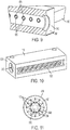
FIG. 6 is a perspective view of an orifice insert in accordance with embodiments; -
FIG. 7 is a perspective view of the orifice insert ofFIG. 6 in accordance with embodiments; -
FIG. 8 is a side view of an orifice insert ofFIGS. 6 and 7 interposed between an inlet header and a channel in accordance with embodiments; -
FIG. 9 is a perspective view of orifice inserts ofFIGS. 6 and 7 interposed between an inlet header and channels in accordance with embodiments; -
FIG. 10 is a perspective view of orifice inserts ofFIGS. 6 and 7 seated in an external groove of an inlet header in accordance with embodiments; and -
FIG. 11 is an axial view of an orifice insert and a grooved channel in the background to illustrate movement of liquid through the orifice insert in accordance with embodiments. - These and other advantages and features will become more apparent from the following description taken in conjunction with the drawings.
- Movement of liquid in a microgravity environment is mainly dictated by a surface tension of the liquid, characteristics of a surface the liquid is intended to be in contact with and external disturbances applied to the system. In a terrestrial environment, the liquid will tend to pool and flow in the direction of gravity. In either case, in a properly designed groove, liquid can be replenished into the groove and vapor can be expelled out of the groove at similar rates which is useful in the replenishment of liquid on an evaporating surface of an evaporator. As such, as will be described below, a groove geometry in which liquid can be replenished into the groove and vapor can be expelled out of the groove at similar rates in integrated into an evaporator design. The evaporator design is therefore suitable for both terrestrial and microgravity environments. Multiple flow distributors placed at the inflow header provide a desired back pressure which ensures uniform flow distribution among multiple parallel flow channels in the evaporator. The flow channels in the flow distributor guide the liquid directly to the grooves. The combination of flow distributor and grooved channels ensure an efficient evaporator operation.
- With reference to
FIGS. 1-3 , anevaporator element 101 is provided and includes a first header (hereinafter referred to as an "inlet header") 110, a second header (hereinafter referred to as an "outlet header") 120 and abody 130. Thebody 130 is formed to definechannels 140 that may be arranged in alinear formation 141 across a width W of thebody 130. Each of thechannels 140 can have a substantially same shape as the others and includesgrooves 142 that are circumferentially arrayed to extend radially outwardly from an opencentral region 143. - Each of the
grooves 142 has a same shape as the others and is immediately adjacent to neighboringgrooves 142. In addition, each of thegrooves 142 is delimited by first and second interior facing sidewalls 144 of thebody 130. The first and secondinterior facing sidewalls 144 are tapered toward each other to form a base B and an apex A. The apex A is opposite the base B and has an apex angle 2β where β is less than 90° minus a solid-liquid contact angle. That is, the apex angle 2β is defined such that, for a fluid flow moving through one of thechannels 140 in a microgravity environment where a portion of the fluid flow is in a liquid phase and another portion of the fluid flow is in a vapor phase, the portion of the fluid flow in the liquid phase within aparticular groove 142 of thechannel 140 will move in theparticular groove 142 from the base B to the apex A and the portion of the fluid flow in the vapor phase within theparticular groove 142 will move in theparticular groove 142 from the apex A to the base B. - With reference to
FIG. 4 , an operation of thechannels 140 and thegrooves 142 in a microgravity environment is illustrated. As shown inFIG. 4 , in the microgravity environment, once liquid contacts the first and second interior facing sidewalls 144 of each of thegrooves 142, the liquid moves in the direction from the base B and to the apex A. After vaporization by exposure of thebody 130 to heat, the vapor is expelled from the apex A toward the base B and to the opencentral region 143. - With reference to
FIG. 5 , an operation of thechannels 140 and thegrooves 142 in a gravity field is illustrated. As shown inFIG. 5 , due to the influence of gravity, the liquid is mostly accumulated at the bottom portion of thechannels 140. Nevertheless, since heat applied to thebody 130 can be conducted to the liquid, vaporization of the liquid is still possible. - With reference to
FIGS. 6 and 7 , anorifice insert 601 is provided and includes acenter plug 610 and aring feature 620. Thecenter plug 610 has afirst end 611, asecond end 612 opposite thefirst end 611 and anexterior surface 613 that extends between the first and second ends 611 and 612. Theexterior surface 613 has a curved plane P and is formed to definemultiple inflow channels 630 that extend from thefirst end 611 toward thesecond end 612 and that terminate attermination points 631 defined midway between the first and second ends 611 and 612. Each of themultiple inflow channels 630 has au-shaped cross-section 632 that is directed inwardly from the curved plane P. Thering feature 620 is disposed about thecenter plug 610 and themultiple inflow channels 630 and includes anaxial face 621 and aradial face 622. Theaxial face 621 is adjacent to thecenter plug 610 and themultiple inflow channels 630. Theradial face 622 is disposed at a distal edge of theaxial face 621 and is oriented to face radially inwardly toward thecenter plug 610 and themultiple inflow channels 630. Thering feature 620 is thus disposed to define, with thecenter plug 610, aplenum 640 with which the termination points 631 of themultiple inflow channels 630 are fluidly communicative. Theplenum 640 extends circumferentially about thecenter plug 610 and themultiple inflow channels 630. Themultiple inflow channels 630 thus extend beneath thering feature 620 in a radial dimension. The termination points 631 are axially aligned with theplenum 640 and can be scalloped or otherwise configured to direct fluid flow moving along themultiple inflow channels 630 radially outwardly and into theplenum 640. - The
multiple inflow channels 630 are designed and configured to create a desired back pressure to achieve proper flow distribution among thechannels 140 in the body 130 (seeFIGS. 1 and 2 ). Fluid moving along one of themultiple inflow channels 630 flows from thefirst end 611 and toward thesecond end 612. The fluid passes beneath thering feature 620 in a radial dimension and interacts with thecorresponding termination point 631. This interaction causes the fluid to enter theplenum 640 and to flow in a circumferential direction. - With reference back to
FIG. 1 and with additional reference toFIGS. 8-11 , orifice inserts 601 are respectively interposable between theinlet header 110 and acorresponding channel 140 in thebody 130 of the evaporator element 101 (seFIG. 1 ). As shown inFIGS. 9 and 10 , theinlet header 110 includes aheader body 901 that is formed to define a central cavity 910 (seeFIG. 8 ),apertures 920 for fluid communication between thecentral cavity 910 and thechannels 140 and anexternal groove 930. The orifice inserts 601 are respectively insertable into corresponding ones of theapertures 920 and are seatable in theexternal groove 930 to respectively register with corresponding ones of thechannels 140. Where the correspondingchannel 140 has thegrooves 142 as described above, theorifice insert 601 is disposed and configured to encourage fluid of the fluid flow from theinlet header 110 to thecorresponding channel 140 to flow into thegrooves 142 of thecorresponding channel 140. - In an operation of the
evaporator 101 with the orifice inserts 601 respectively interposed between theinlet header 110 andcorresponding channels 140 in thebody 130 of theevaporator element 101, liquid entering theinlet header 110 is distributed to each of the apertures 1120 by the central cavity 1110. Once the liquid enters an aperture 1120, the liquid is forced into themultiple inflow channels 630 and flows along themultiple inflow channels 630 to the termination points 631. The termination points 631 redirect the liquid into theplenum 640 whereupon the liquid is directed into thegrooves 142 of thechannels 140. - Technical effects and benefits of the features described herein are the provision of an evaporator with properly designed grooves and flow distributors that can be used in either terrestrial or microgravity environments. In microgravity environments, the grooves are capable of replenishing liquid to evaporating surfaces that ensure the evaporator operation is proper and efficient. In addition to this self-wetting capability, the addition of the groove surface areas increases the evaporative surface area and improves the evaporator performance in both the terrestrial and the microgravity environments.
- While the disclosure is provided in detail in connection with only a limited number of embodiments, it should be readily understood that the disclosure is not limited to such disclosed embodiments. Rather, the disclosure can be modified to incorporate any number of variations, alterations, substitutions or equivalent arrangements not heretofore described, but which are within the scope of the invention as defined by the claims. Additionally, while various embodiments of the disclosure have been described, it is to be understood that the exemplary embodiment(s) may include only some of the described exemplary aspects. Accordingly, the disclosure is not to be seen as limited by the foregoing description, but is only limited by the scope of the appended claims.
Claims (12)
- An orifice insert, comprising:a center plug (610) having first (611) and second (612) ends and an exterior surface (613) extending between the first and second ends,the exterior surface defining multiple inflow channels (630) that extend from the first end toward the second end and terminate at termination points (631) midway between the first and second ends; anda ring feature (620) disposed about the center plug and the multiple inflow channels to define, with the center plug, a plenum (640) with which the termination points of the multiple inflow channels are fluidly communicative.
- The orifice insert according to claim 1, wherein:the exterior surface has a curved plane at each of the multiple inflow channels, andeach of the multiple inflow channels has a u-shape cross-section directed inwardly from the curved plane.
- The orifice insert according to claim 1 or 2, wherein the termination points of each of the multiple inflow channels are scalloped.
- The orifice insert according to claim 1, 2 or 3, wherein the plenum extends circumferentially about the center plug and the multiple inflow channels.
- The orifice insert according to any preceding claim, wherein the ring feature comprises:an axial face (621) adjacent to the center plug and the multiple inflow channels; anda radial face (622) at a distal edge of the axial face to face the center plug and the multiple inflow channels.
- An evaporator, comprising:an inlet header (110);a body (130) defining channels (140), each of which comprises grooves (142) circumferentially arranged about an open central region to extend radially outwardly from the open central region; andorifice inserts (601) respectively interposable between the inlet header and a corresponding channel to respectively encourage fluid flow from the inlet header to the corresponding channel to flow into the grooves.
- The evaporator according to claim 6, wherein:the inlet header comprises a header body defining a cavity, apertures for fluid communication and an external groove, andthe orifice inserts are respectively insertible into corresponding apertures and seatable in the external groove.
- The evaporator according to claim 6, wherein each orifice insert is an orifice insert as claimed in any of claims 1 to 5.
- An evaporator, comprising:an inlet header (110);a body (130) defining channels (140); andorifice inserts (601) respectively interposable between the inlet header and corresponding channels,each channel comprising grooves (142) respectively delimited by first and second interior facing sidewalls (144) of the body which form a base and an apex with an apex angle opposite the base and defined such that, for a fluid flow moving through one of the channels in a microgravity environment:a portion of the fluid flow in a liquid phase within a groove of the channel will move in the groove from the base to the apex, anda portion of the fluid flow in a vapor phase within a groove of the channel will move in the groove from the apex to the base, andeach orifice insert is configured to encourage fluid flow from the inlet header to the corresponding channel to flow into the grooves.
- The evaporator according to claim 9, wherein the apex angle is 2β, where β is less than 90° minus a solid-liquid contact angle.
- The evaporator according to claim 9 or 10, wherein:the inlet header comprises a header body defining a cavity, apertures for fluid communication and an external groove,the orifice inserts are respectively insertible into corresponding apertures and seatable in the external groove.
- The evaporator according to claim 13, wherein each orifice insert is an orifice insert as claimed in claims 1 to 5.
Applications Claiming Priority (1)
| Application Number | Priority Date | Filing Date | Title |
|---|---|---|---|
| US16/780,159 US11808528B2 (en) | 2020-02-03 | 2020-02-03 | Evaporator with grooved channels and orifice inserts |
Publications (2)
| Publication Number | Publication Date |
|---|---|
| EP3859259A1 true EP3859259A1 (en) | 2021-08-04 |
| EP3859259B1 EP3859259B1 (en) | 2023-08-09 |
Family
ID=74550481
Family Applications (1)
| Application Number | Title | Priority Date | Filing Date |
|---|---|---|---|
| EP21154911.8A Active EP3859259B1 (en) | 2020-02-03 | 2021-02-03 | Evaporator with grooved channels |
Country Status (2)
| Country | Link |
|---|---|
| US (2) | US11808528B2 (en) |
| EP (1) | EP3859259B1 (en) |
Cited By (1)
| Publication number | Priority date | Publication date | Assignee | Title |
|---|---|---|---|---|
| EP4140897A1 (en) * | 2021-08-26 | 2023-03-01 | Hamilton Sundstrand Corporation | Adjustable port size insert |
Families Citing this family (1)
| Publication number | Priority date | Publication date | Assignee | Title |
|---|---|---|---|---|
| US11718423B2 (en) * | 2021-12-17 | 2023-08-08 | Hamilton Sundstrand Corporation | Condensing heat exchanger with flow restricting inserts between the condenser element and the outlet header |
Citations (6)
| Publication number | Priority date | Publication date | Assignee | Title |
|---|---|---|---|---|
| US20050051318A1 (en) * | 2002-11-29 | 2005-03-10 | Calsonic Kansei Corporation | Heat exchanger |
| JP2006010119A (en) * | 2004-06-23 | 2006-01-12 | Seizo Hataya | Thin pipe group heat exchanger, heat exchanger, manufacturing method, and heat pipe |
| US20070130769A1 (en) * | 2002-09-03 | 2007-06-14 | Moon Seok H | Micro heat pipe with pligonal cross-section manufactured via extrusion or drawing |
| EP2357440A1 (en) * | 2008-11-03 | 2011-08-17 | Nanjing Ecoway Energy Technology Co., Ltd. | Heat pipe with micro-pore tubes array and making method thereof and heat exchanging system |
| US8234881B2 (en) * | 2008-08-28 | 2012-08-07 | Johnson Controls Technology Company | Multichannel heat exchanger with dissimilar flow |
| WO2014125260A1 (en) * | 2013-02-12 | 2014-08-21 | Ray Newton | Heat exchanger optimisation apparatus and method of use thereof |
Family Cites Families (27)
| Publication number | Priority date | Publication date | Assignee | Title |
|---|---|---|---|---|
| JPS5253771A (en) * | 1975-10-30 | 1977-04-30 | Babcock Hitachi Kk | Multiple effec evaporator for making water |
| US4513587A (en) * | 1981-09-14 | 1985-04-30 | Sueddeutsche Kuehlerfabrik Julius Fr. Behr Gmbh & Co., Kg | Evaporator particularly suitable for air conditioners in automotive vehicles |
| JPS62118502A (en) * | 1985-11-18 | 1987-05-29 | 富士通株式会社 | Temperature variable resistance |
| DE3810128C1 (en) | 1988-03-25 | 1989-09-07 | Erno Raumfahrttechnik Gmbh, 2800 Bremen, De | |
| US4869313A (en) | 1988-07-15 | 1989-09-26 | General Electric Company | Low pressure drop condenser/evaporator pump heat exchanger |
| DE3921485A1 (en) | 1989-06-30 | 1991-01-10 | Erno Raumfahrttechnik Gmbh | EVAPORATION HEAT EXCHANGER |
| DE4104432C1 (en) | 1991-02-14 | 1992-04-09 | Erno Raumfahrttechnik Gmbh, 2800 Bremen, De | |
| JP2555056Y2 (en) | 1991-07-30 | 1997-11-19 | 石川島播磨重工業株式会社 | Plate fin type flash evaporator for heat control system exhaust heat of spacecraft |
| US20040244382A1 (en) | 1992-10-27 | 2004-12-09 | Hagen David L. | Distributed direct fluid contactor |
| DE19617916B4 (en) | 1996-05-03 | 2007-02-01 | Airbus Deutschland Gmbh | Evaporator for evaporating a cryogenic liquid medium |
| JPH1144498A (en) * | 1997-05-30 | 1999-02-16 | Showa Alum Corp | Flat perforated tube for heat exchanger and heat exchanger using the tube |
| US6190616B1 (en) * | 1997-09-11 | 2001-02-20 | Molecular Dynamics, Inc. | Capillary valve, connector, and router |
| SE0101636D0 (en) | 2001-05-10 | 2001-05-10 | Emerson Energy Systems Ab | Apparatus and method for improving the performance of an evaporator |
| DE10303595B4 (en) * | 2003-01-30 | 2005-02-17 | Visteon Global Technologies, Inc., Dearborn | Multi-channel heat exchanger and connection unit |
| US20050042042A1 (en) * | 2003-07-16 | 2005-02-24 | Neville Clarke | Movement modification of feed streams in separation apparatus |
| US7080683B2 (en) * | 2004-06-14 | 2006-07-25 | Delphi Technologies, Inc. | Flat tube evaporator with enhanced refrigerant flow passages |
| ES2365740T3 (en) | 2005-02-02 | 2011-10-10 | Carrier Corporation | HEAT EXCHANGER WITH FLUID EXPANSION IN MULTIPLE STAGES IN THE COLLECTOR. |
| US7866638B2 (en) | 2005-02-14 | 2011-01-11 | Neumann Systems Group, Inc. | Gas liquid contactor and effluent cleaning system and method |
| FR2912995B1 (en) | 2007-02-26 | 2009-05-22 | Alcatel Lucent Sas | THERMAL CONTROL DEVICE ON BOARD A SPACE ENGINE |
| US20090294112A1 (en) * | 2008-06-03 | 2009-12-03 | Nordyne, Inc. | Internally finned tube having enhanced nucleation centers, heat exchangers, and methods of manufacture |
| JP5100818B2 (en) | 2010-11-05 | 2012-12-19 | 三菱電機株式会社 | Refrigerant distributor, heat exchanger and refrigeration cycle apparatus |
| US8961019B2 (en) * | 2011-05-10 | 2015-02-24 | Smith International, Inc. | Flow control through thrust bearing assembly |
| US9897398B2 (en) * | 2013-05-07 | 2018-02-20 | United Technologies Corporation | Extreme environment heat exchanger |
| WO2015026483A1 (en) * | 2013-08-21 | 2015-02-26 | Gtat Corporation | Using an active solder to couple a metallic article to a photovoltaic cell |
| US20160010485A1 (en) | 2014-07-09 | 2016-01-14 | Aerojet Rocketdyne, Inc. | Combined cycle propulsion system |
| US20180285497A1 (en) | 2017-03-31 | 2018-10-04 | The Government Of The United States Of America, As Represented By The Secretary Of The Navy | Numerical Modeling and Performance Analysis of a Scramjet Engine with a Controllable Waverider Inlet Design |
| US11512908B2 (en) | 2020-02-03 | 2022-11-29 | Hamilton Sundstrand Corporation | Evaporator with grooved channels |
-
2020
- 2020-02-03 US US16/780,159 patent/US11808528B2/en active Active
-
2021
- 2021-02-03 EP EP21154911.8A patent/EP3859259B1/en active Active
-
2023
- 2023-10-03 US US18/480,114 patent/US20240027141A1/en active Pending
Patent Citations (6)
| Publication number | Priority date | Publication date | Assignee | Title |
|---|---|---|---|---|
| US20070130769A1 (en) * | 2002-09-03 | 2007-06-14 | Moon Seok H | Micro heat pipe with pligonal cross-section manufactured via extrusion or drawing |
| US20050051318A1 (en) * | 2002-11-29 | 2005-03-10 | Calsonic Kansei Corporation | Heat exchanger |
| JP2006010119A (en) * | 2004-06-23 | 2006-01-12 | Seizo Hataya | Thin pipe group heat exchanger, heat exchanger, manufacturing method, and heat pipe |
| US8234881B2 (en) * | 2008-08-28 | 2012-08-07 | Johnson Controls Technology Company | Multichannel heat exchanger with dissimilar flow |
| EP2357440A1 (en) * | 2008-11-03 | 2011-08-17 | Nanjing Ecoway Energy Technology Co., Ltd. | Heat pipe with micro-pore tubes array and making method thereof and heat exchanging system |
| WO2014125260A1 (en) * | 2013-02-12 | 2014-08-21 | Ray Newton | Heat exchanger optimisation apparatus and method of use thereof |
Cited By (1)
| Publication number | Priority date | Publication date | Assignee | Title |
|---|---|---|---|---|
| EP4140897A1 (en) * | 2021-08-26 | 2023-03-01 | Hamilton Sundstrand Corporation | Adjustable port size insert |
Also Published As
| Publication number | Publication date |
|---|---|
| US20210239408A1 (en) | 2021-08-05 |
| EP3859259B1 (en) | 2023-08-09 |
| US20240027141A1 (en) | 2024-01-25 |
| US11808528B2 (en) | 2023-11-07 |
Similar Documents
| Publication | Publication Date | Title |
|---|---|---|
| US20240027141A1 (en) | Evaporator with grooved channels | |
| EP3859258A1 (en) | Evaporator with grooved channels | |
| JP4291956B2 (en) | A falling film evaporator with a two-stage refrigerant dispersion device. | |
| JP3705859B2 (en) | Heat exchanger with distribution device | |
| US7597135B2 (en) | Impingement cooled heat sink with low pressure drop | |
| EP2878911B1 (en) | Heat exchanger | |
| JP5972457B2 (en) | Plate heat exchanger and its use | |
| JP6082105B2 (en) | Plate heat exchanger with injection means | |
| EP2977707B1 (en) | Flow distributor for heat transfer plate | |
| KR20150108823A (en) | Plate heat exchanger | |
| US5161610A (en) | Evaporation heat exchanger, especially for a spacecraft | |
| JP2003506663A (en) | Plate heat exchanger | |
| US20190048954A1 (en) | Frictional piece | |
| CN117044080A (en) | Housing for electric motor with self-venting cooling jacket | |
| KR102621527B1 (en) | Rotor sleeve for motor and motor for vehicle including the same | |
| JP4568973B2 (en) | Plate type heat exchanger | |
| EP3859239A2 (en) | Insert for evaporator header | |
| JP2007513481A (en) | Small fuel cell inlet fuel gas distributor with low pressure drop | |
| JP2006349229A (en) | Refrigerant shunt | |
| US8167496B2 (en) | Slide bearing | |
| EP3819562A1 (en) | Swirl generator, associated evaporator, and associated method | |
| JP7119200B2 (en) | Cooling system | |
| JP2764174B2 (en) | Falling liquid film evaporator | |
| JP2018526605A (en) | Heat exchanger and vehicle air conditioning system | |
| US11718423B2 (en) | Condensing heat exchanger with flow restricting inserts between the condenser element and the outlet header |
Legal Events
| Date | Code | Title | Description |
|---|---|---|---|
| PUAI | Public reference made under article 153(3) epc to a published international application that has entered the european phase |
Free format text: ORIGINAL CODE: 0009012 |
|
| STAA | Information on the status of an ep patent application or granted ep patent |
Free format text: STATUS: THE APPLICATION HAS BEEN PUBLISHED |
|
| AK | Designated contracting states |
Kind code of ref document: A1 Designated state(s): AL AT BE BG CH CY CZ DE DK EE ES FI FR GB GR HR HU IE IS IT LI LT LU LV MC MK MT NL NO PL PT RO RS SE SI SK SM TR |
|
| STAA | Information on the status of an ep patent application or granted ep patent |
Free format text: STATUS: REQUEST FOR EXAMINATION WAS MADE |
|
| 17P | Request for examination filed |
Effective date: 20220204 |
|
| RBV | Designated contracting states (corrected) |
Designated state(s): AL AT BE BG CH CY CZ DE DK EE ES FI FR GB GR HR HU IE IS IT LI LT LU LV MC MK MT NL NO PL PT RO RS SE SI SK SM TR |
|
| GRAP | Despatch of communication of intention to grant a patent |
Free format text: ORIGINAL CODE: EPIDOSNIGR1 |
|
| STAA | Information on the status of an ep patent application or granted ep patent |
Free format text: STATUS: GRANT OF PATENT IS INTENDED |
|
| INTG | Intention to grant announced |
Effective date: 20230328 |
|
| GRAS | Grant fee paid |
Free format text: ORIGINAL CODE: EPIDOSNIGR3 |
|
| GRAA | (expected) grant |
Free format text: ORIGINAL CODE: 0009210 |
|
| STAA | Information on the status of an ep patent application or granted ep patent |
Free format text: STATUS: THE PATENT HAS BEEN GRANTED |
|
| AK | Designated contracting states |
Kind code of ref document: B1 Designated state(s): AL AT BE BG CH CY CZ DE DK EE ES FI FR GB GR HR HU IE IS IT LI LT LU LV MC MK MT NL NO PL PT RO RS SE SI SK SM TR |
|
| REG | Reference to a national code |
Ref country code: GB Ref legal event code: FG4D |
|
| REG | Reference to a national code |
Ref country code: CH Ref legal event code: EP |
|
| REG | Reference to a national code |
Ref country code: DE Ref legal event code: R096 Ref document number: 602021004043 Country of ref document: DE |
|
| REG | Reference to a national code |
Ref country code: IE Ref legal event code: FG4D |
|
| REG | Reference to a national code |
Ref country code: LT Ref legal event code: MG9D |
|
| REG | Reference to a national code |
Ref country code: NL Ref legal event code: MP Effective date: 20230809 |
|
| REG | Reference to a national code |
Ref country code: AT Ref legal event code: MK05 Ref document number: 1597969 Country of ref document: AT Kind code of ref document: T Effective date: 20230809 |
|
| PG25 | Lapsed in a contracting state [announced via postgrant information from national office to epo] |
Ref country code: GR Free format text: LAPSE BECAUSE OF FAILURE TO SUBMIT A TRANSLATION OF THE DESCRIPTION OR TO PAY THE FEE WITHIN THE PRESCRIBED TIME-LIMIT Effective date: 20231110 |
|
| PG25 | Lapsed in a contracting state [announced via postgrant information from national office to epo] |
Ref country code: IS Free format text: LAPSE BECAUSE OF FAILURE TO SUBMIT A TRANSLATION OF THE DESCRIPTION OR TO PAY THE FEE WITHIN THE PRESCRIBED TIME-LIMIT Effective date: 20231209 |
|
| PG25 | Lapsed in a contracting state [announced via postgrant information from national office to epo] |
Ref country code: SE Free format text: LAPSE BECAUSE OF FAILURE TO SUBMIT A TRANSLATION OF THE DESCRIPTION OR TO PAY THE FEE WITHIN THE PRESCRIBED TIME-LIMIT Effective date: 20230809 Ref country code: RS Free format text: LAPSE BECAUSE OF FAILURE TO SUBMIT A TRANSLATION OF THE DESCRIPTION OR TO PAY THE FEE WITHIN THE PRESCRIBED TIME-LIMIT Effective date: 20230809 Ref country code: PT Free format text: LAPSE BECAUSE OF FAILURE TO SUBMIT A TRANSLATION OF THE DESCRIPTION OR TO PAY THE FEE WITHIN THE PRESCRIBED TIME-LIMIT Effective date: 20231211 Ref country code: NO Free format text: LAPSE BECAUSE OF FAILURE TO SUBMIT A TRANSLATION OF THE DESCRIPTION OR TO PAY THE FEE WITHIN THE PRESCRIBED TIME-LIMIT Effective date: 20231109 Ref country code: NL Free format text: LAPSE BECAUSE OF FAILURE TO SUBMIT A TRANSLATION OF THE DESCRIPTION OR TO PAY THE FEE WITHIN THE PRESCRIBED TIME-LIMIT Effective date: 20230809 Ref country code: LV Free format text: LAPSE BECAUSE OF FAILURE TO SUBMIT A TRANSLATION OF THE DESCRIPTION OR TO PAY THE FEE WITHIN THE PRESCRIBED TIME-LIMIT Effective date: 20230809 Ref country code: LT Free format text: LAPSE BECAUSE OF FAILURE TO SUBMIT A TRANSLATION OF THE DESCRIPTION OR TO PAY THE FEE WITHIN THE PRESCRIBED TIME-LIMIT Effective date: 20230809 Ref country code: IS Free format text: LAPSE BECAUSE OF FAILURE TO SUBMIT A TRANSLATION OF THE DESCRIPTION OR TO PAY THE FEE WITHIN THE PRESCRIBED TIME-LIMIT Effective date: 20231209 Ref country code: HR Free format text: LAPSE BECAUSE OF FAILURE TO SUBMIT A TRANSLATION OF THE DESCRIPTION OR TO PAY THE FEE WITHIN THE PRESCRIBED TIME-LIMIT Effective date: 20230809 Ref country code: GR Free format text: LAPSE BECAUSE OF FAILURE TO SUBMIT A TRANSLATION OF THE DESCRIPTION OR TO PAY THE FEE WITHIN THE PRESCRIBED TIME-LIMIT Effective date: 20231110 Ref country code: FI Free format text: LAPSE BECAUSE OF FAILURE TO SUBMIT A TRANSLATION OF THE DESCRIPTION OR TO PAY THE FEE WITHIN THE PRESCRIBED TIME-LIMIT Effective date: 20230809 Ref country code: AT Free format text: LAPSE BECAUSE OF FAILURE TO SUBMIT A TRANSLATION OF THE DESCRIPTION OR TO PAY THE FEE WITHIN THE PRESCRIBED TIME-LIMIT Effective date: 20230809 |
|
| PG25 | Lapsed in a contracting state [announced via postgrant information from national office to epo] |
Ref country code: PL Free format text: LAPSE BECAUSE OF FAILURE TO SUBMIT A TRANSLATION OF THE DESCRIPTION OR TO PAY THE FEE WITHIN THE PRESCRIBED TIME-LIMIT Effective date: 20230809 |
|
| PG25 | Lapsed in a contracting state [announced via postgrant information from national office to epo] |
Ref country code: ES Free format text: LAPSE BECAUSE OF FAILURE TO SUBMIT A TRANSLATION OF THE DESCRIPTION OR TO PAY THE FEE WITHIN THE PRESCRIBED TIME-LIMIT Effective date: 20230809 |
|
| PG25 | Lapsed in a contracting state [announced via postgrant information from national office to epo] |
Ref country code: SM Free format text: LAPSE BECAUSE OF FAILURE TO SUBMIT A TRANSLATION OF THE DESCRIPTION OR TO PAY THE FEE WITHIN THE PRESCRIBED TIME-LIMIT Effective date: 20230809 Ref country code: RO Free format text: LAPSE BECAUSE OF FAILURE TO SUBMIT A TRANSLATION OF THE DESCRIPTION OR TO PAY THE FEE WITHIN THE PRESCRIBED TIME-LIMIT Effective date: 20230809 Ref country code: ES Free format text: LAPSE BECAUSE OF FAILURE TO SUBMIT A TRANSLATION OF THE DESCRIPTION OR TO PAY THE FEE WITHIN THE PRESCRIBED TIME-LIMIT Effective date: 20230809 Ref country code: EE Free format text: LAPSE BECAUSE OF FAILURE TO SUBMIT A TRANSLATION OF THE DESCRIPTION OR TO PAY THE FEE WITHIN THE PRESCRIBED TIME-LIMIT Effective date: 20230809 Ref country code: DK Free format text: LAPSE BECAUSE OF FAILURE TO SUBMIT A TRANSLATION OF THE DESCRIPTION OR TO PAY THE FEE WITHIN THE PRESCRIBED TIME-LIMIT Effective date: 20230809 Ref country code: CZ Free format text: LAPSE BECAUSE OF FAILURE TO SUBMIT A TRANSLATION OF THE DESCRIPTION OR TO PAY THE FEE WITHIN THE PRESCRIBED TIME-LIMIT Effective date: 20230809 Ref country code: SK Free format text: LAPSE BECAUSE OF FAILURE TO SUBMIT A TRANSLATION OF THE DESCRIPTION OR TO PAY THE FEE WITHIN THE PRESCRIBED TIME-LIMIT Effective date: 20230809 |
|
| REG | Reference to a national code |
Ref country code: DE Ref legal event code: R097 Ref document number: 602021004043 Country of ref document: DE |
|
| PG25 | Lapsed in a contracting state [announced via postgrant information from national office to epo] |
Ref country code: IT Free format text: LAPSE BECAUSE OF FAILURE TO SUBMIT A TRANSLATION OF THE DESCRIPTION OR TO PAY THE FEE WITHIN THE PRESCRIBED TIME-LIMIT Effective date: 20230809 |
|
| PLBE | No opposition filed within time limit |
Free format text: ORIGINAL CODE: 0009261 |
|
| STAA | Information on the status of an ep patent application or granted ep patent |
Free format text: STATUS: NO OPPOSITION FILED WITHIN TIME LIMIT |
|
| 26N | No opposition filed |
Effective date: 20240513 |
|
| PG25 | Lapsed in a contracting state [announced via postgrant information from national office to epo] |
Ref country code: SI Free format text: LAPSE BECAUSE OF FAILURE TO SUBMIT A TRANSLATION OF THE DESCRIPTION OR TO PAY THE FEE WITHIN THE PRESCRIBED TIME-LIMIT Effective date: 20230809 |
|
| PG25 | Lapsed in a contracting state [announced via postgrant information from national office to epo] |
Ref country code: MC Free format text: LAPSE BECAUSE OF FAILURE TO SUBMIT A TRANSLATION OF THE DESCRIPTION OR TO PAY THE FEE WITHIN THE PRESCRIBED TIME-LIMIT Effective date: 20230809 |
|
| REG | Reference to a national code |
Ref country code: CH Ref legal event code: PL |
|
| PG25 | Lapsed in a contracting state [announced via postgrant information from national office to epo] |
Ref country code: LU Free format text: LAPSE BECAUSE OF NON-PAYMENT OF DUE FEES Effective date: 20240203 |
|
| PG25 | Lapsed in a contracting state [announced via postgrant information from national office to epo] |
Ref country code: CH Free format text: LAPSE BECAUSE OF NON-PAYMENT OF DUE FEES Effective date: 20240229 |
|
| PG25 | Lapsed in a contracting state [announced via postgrant information from national office to epo] |
Ref country code: LU Free format text: LAPSE BECAUSE OF NON-PAYMENT OF DUE FEES Effective date: 20240203 Ref country code: CH Free format text: LAPSE BECAUSE OF NON-PAYMENT OF DUE FEES Effective date: 20240229 |
|
| PG25 | Lapsed in a contracting state [announced via postgrant information from national office to epo] |
Ref country code: BG Free format text: LAPSE BECAUSE OF FAILURE TO SUBMIT A TRANSLATION OF THE DESCRIPTION OR TO PAY THE FEE WITHIN THE PRESCRIBED TIME-LIMIT Effective date: 20230809 |
|
| PG25 | Lapsed in a contracting state [announced via postgrant information from national office to epo] |
Ref country code: BG Free format text: LAPSE BECAUSE OF FAILURE TO SUBMIT A TRANSLATION OF THE DESCRIPTION OR TO PAY THE FEE WITHIN THE PRESCRIBED TIME-LIMIT Effective date: 20230809 |
|
| REG | Reference to a national code |
Ref country code: BE Ref legal event code: MM Effective date: 20240229 |
|
| PG25 | Lapsed in a contracting state [announced via postgrant information from national office to epo] |
Ref country code: BE Free format text: LAPSE BECAUSE OF NON-PAYMENT OF DUE FEES Effective date: 20240229 |
|
| PG25 | Lapsed in a contracting state [announced via postgrant information from national office to epo] |
Ref country code: IE Free format text: LAPSE BECAUSE OF NON-PAYMENT OF DUE FEES Effective date: 20240203 |
|
| PG25 | Lapsed in a contracting state [announced via postgrant information from national office to epo] |
Ref country code: IE Free format text: LAPSE BECAUSE OF NON-PAYMENT OF DUE FEES Effective date: 20240203 Ref country code: BE Free format text: LAPSE BECAUSE OF NON-PAYMENT OF DUE FEES Effective date: 20240229 |
|
| PG25 | Lapsed in a contracting state [announced via postgrant information from national office to epo] |
Ref country code: CY Free format text: LAPSE BECAUSE OF FAILURE TO SUBMIT A TRANSLATION OF THE DESCRIPTION OR TO PAY THE FEE WITHIN THE PRESCRIBED TIME-LIMIT; INVALID AB INITIO Effective date: 20210203 |
|
| PG25 | Lapsed in a contracting state [announced via postgrant information from national office to epo] |
Ref country code: HU Free format text: LAPSE BECAUSE OF FAILURE TO SUBMIT A TRANSLATION OF THE DESCRIPTION OR TO PAY THE FEE WITHIN THE PRESCRIBED TIME-LIMIT; INVALID AB INITIO Effective date: 20210203 |
|
| PG25 | Lapsed in a contracting state [announced via postgrant information from national office to epo] |
Ref country code: TR Free format text: LAPSE BECAUSE OF FAILURE TO SUBMIT A TRANSLATION OF THE DESCRIPTION OR TO PAY THE FEE WITHIN THE PRESCRIBED TIME-LIMIT Effective date: 20230809 |
|
| P01 | Opt-out of the competence of the unified patent court (upc) registered |
Free format text: CASE NUMBER: UPC_APP_0018589_3859259/2025 Effective date: 20251219 |
|
| PGFP | Annual fee paid to national office [announced via postgrant information from national office to epo] |
Ref country code: GB Payment date: 20260121 Year of fee payment: 6 |
|
| PGFP | Annual fee paid to national office [announced via postgrant information from national office to epo] |
Ref country code: DE Payment date: 20260121 Year of fee payment: 6 |
|
| PGFP | Annual fee paid to national office [announced via postgrant information from national office to epo] |
Ref country code: FR Payment date: 20260121 Year of fee payment: 6 |