EP3859216A1 - Heat pump and method thereof - Google Patents
Heat pump and method thereof Download PDFInfo
- Publication number
- EP3859216A1 EP3859216A1 EP21154288.1A EP21154288A EP3859216A1 EP 3859216 A1 EP3859216 A1 EP 3859216A1 EP 21154288 A EP21154288 A EP 21154288A EP 3859216 A1 EP3859216 A1 EP 3859216A1
- Authority
- EP
- European Patent Office
- Prior art keywords
- water
- boiler
- temperature
- heating
- heat pump
- Prior art date
- Legal status (The legal status is an assumption and is not a legal conclusion. Google has not performed a legal analysis and makes no representation as to the accuracy of the status listed.)
- Granted
Links
Images



Classifications
-
- F—MECHANICAL ENGINEERING; LIGHTING; HEATING; WEAPONS; BLASTING
- F25—REFRIGERATION OR COOLING; COMBINED HEATING AND REFRIGERATION SYSTEMS; HEAT PUMP SYSTEMS; MANUFACTURE OR STORAGE OF ICE; LIQUEFACTION SOLIDIFICATION OF GASES
- F25B—REFRIGERATION MACHINES, PLANTS OR SYSTEMS; COMBINED HEATING AND REFRIGERATION SYSTEMS; HEAT PUMP SYSTEMS
- F25B30/00—Heat pumps
- F25B30/02—Heat pumps of the compression type
-
- F—MECHANICAL ENGINEERING; LIGHTING; HEATING; WEAPONS; BLASTING
- F24—HEATING; RANGES; VENTILATING
- F24D—DOMESTIC- OR SPACE-HEATING SYSTEMS, e.g. CENTRAL HEATING SYSTEMS; DOMESTIC HOT-WATER SUPPLY SYSTEMS; ELEMENTS OR COMPONENTS THEREFOR
- F24D15/00—Other domestic- or space-heating systems
- F24D15/04—Other domestic- or space-heating systems using heat pumps
-
- F—MECHANICAL ENGINEERING; LIGHTING; HEATING; WEAPONS; BLASTING
- F24—HEATING; RANGES; VENTILATING
- F24D—DOMESTIC- OR SPACE-HEATING SYSTEMS, e.g. CENTRAL HEATING SYSTEMS; DOMESTIC HOT-WATER SUPPLY SYSTEMS; ELEMENTS OR COMPONENTS THEREFOR
- F24D19/00—Details
- F24D19/10—Arrangement or mounting of control or safety devices
- F24D19/1006—Arrangement or mounting of control or safety devices for water heating systems
- F24D19/1066—Arrangement or mounting of control or safety devices for water heating systems for the combination of central heating and domestic hot water
-
- F—MECHANICAL ENGINEERING; LIGHTING; HEATING; WEAPONS; BLASTING
- F24—HEATING; RANGES; VENTILATING
- F24D—DOMESTIC- OR SPACE-HEATING SYSTEMS, e.g. CENTRAL HEATING SYSTEMS; DOMESTIC HOT-WATER SUPPLY SYSTEMS; ELEMENTS OR COMPONENTS THEREFOR
- F24D19/00—Details
- F24D19/10—Arrangement or mounting of control or safety devices
- F24D19/1006—Arrangement or mounting of control or safety devices for water heating systems
- F24D19/1066—Arrangement or mounting of control or safety devices for water heating systems for the combination of central heating and domestic hot water
- F24D19/1069—Arrangement or mounting of control or safety devices for water heating systems for the combination of central heating and domestic hot water regulation in function of the temperature of the domestic hot water
-
- F—MECHANICAL ENGINEERING; LIGHTING; HEATING; WEAPONS; BLASTING
- F24—HEATING; RANGES; VENTILATING
- F24D—DOMESTIC- OR SPACE-HEATING SYSTEMS, e.g. CENTRAL HEATING SYSTEMS; DOMESTIC HOT-WATER SUPPLY SYSTEMS; ELEMENTS OR COMPONENTS THEREFOR
- F24D19/00—Details
- F24D19/10—Arrangement or mounting of control or safety devices
- F24D19/1006—Arrangement or mounting of control or safety devices for water heating systems
- F24D19/1066—Arrangement or mounting of control or safety devices for water heating systems for the combination of central heating and domestic hot water
- F24D19/1072—Arrangement or mounting of control or safety devices for water heating systems for the combination of central heating and domestic hot water the system uses a heat pump
-
- F—MECHANICAL ENGINEERING; LIGHTING; HEATING; WEAPONS; BLASTING
- F24—HEATING; RANGES; VENTILATING
- F24H—FLUID HEATERS, e.g. WATER OR AIR HEATERS, HAVING HEAT-GENERATING MEANS, e.g. HEAT PUMPS, IN GENERAL
- F24H15/00—Control of fluid heaters
- F24H15/20—Control of fluid heaters characterised by control inputs
- F24H15/212—Temperature of the water
-
- F—MECHANICAL ENGINEERING; LIGHTING; HEATING; WEAPONS; BLASTING
- F24—HEATING; RANGES; VENTILATING
- F24H—FLUID HEATERS, e.g. WATER OR AIR HEATERS, HAVING HEAT-GENERATING MEANS, e.g. HEAT PUMPS, IN GENERAL
- F24H15/00—Control of fluid heaters
- F24H15/20—Control of fluid heaters characterised by control inputs
- F24H15/258—Outdoor temperature
-
- F—MECHANICAL ENGINEERING; LIGHTING; HEATING; WEAPONS; BLASTING
- F24—HEATING; RANGES; VENTILATING
- F24H—FLUID HEATERS, e.g. WATER OR AIR HEATERS, HAVING HEAT-GENERATING MEANS, e.g. HEAT PUMPS, IN GENERAL
- F24H15/00—Control of fluid heaters
- F24H15/30—Control of fluid heaters characterised by control outputs; characterised by the components to be controlled
- F24H15/375—Control of heat pumps
- F24H15/38—Control of compressors of heat pumps
-
- F—MECHANICAL ENGINEERING; LIGHTING; HEATING; WEAPONS; BLASTING
- F25—REFRIGERATION OR COOLING; COMBINED HEATING AND REFRIGERATION SYSTEMS; HEAT PUMP SYSTEMS; MANUFACTURE OR STORAGE OF ICE; LIQUEFACTION SOLIDIFICATION OF GASES
- F25B—REFRIGERATION MACHINES, PLANTS OR SYSTEMS; COMBINED HEATING AND REFRIGERATION SYSTEMS; HEAT PUMP SYSTEMS
- F25B25/00—Machines, plants or systems, using a combination of modes of operation covered by two or more of the groups F25B1/00 - F25B23/00
- F25B25/005—Machines, plants or systems, using a combination of modes of operation covered by two or more of the groups F25B1/00 - F25B23/00 using primary and secondary systems
-
- F—MECHANICAL ENGINEERING; LIGHTING; HEATING; WEAPONS; BLASTING
- F25—REFRIGERATION OR COOLING; COMBINED HEATING AND REFRIGERATION SYSTEMS; HEAT PUMP SYSTEMS; MANUFACTURE OR STORAGE OF ICE; LIQUEFACTION SOLIDIFICATION OF GASES
- F25B—REFRIGERATION MACHINES, PLANTS OR SYSTEMS; COMBINED HEATING AND REFRIGERATION SYSTEMS; HEAT PUMP SYSTEMS
- F25B33/00—Boilers; Analysers; Rectifiers
-
- F—MECHANICAL ENGINEERING; LIGHTING; HEATING; WEAPONS; BLASTING
- F25—REFRIGERATION OR COOLING; COMBINED HEATING AND REFRIGERATION SYSTEMS; HEAT PUMP SYSTEMS; MANUFACTURE OR STORAGE OF ICE; LIQUEFACTION SOLIDIFICATION OF GASES
- F25B—REFRIGERATION MACHINES, PLANTS OR SYSTEMS; COMBINED HEATING AND REFRIGERATION SYSTEMS; HEAT PUMP SYSTEMS
- F25B41/00—Fluid-circulation arrangements
- F25B41/20—Disposition of valves, e.g. of on-off valves or flow control valves
-
- F—MECHANICAL ENGINEERING; LIGHTING; HEATING; WEAPONS; BLASTING
- F25—REFRIGERATION OR COOLING; COMBINED HEATING AND REFRIGERATION SYSTEMS; HEAT PUMP SYSTEMS; MANUFACTURE OR STORAGE OF ICE; LIQUEFACTION SOLIDIFICATION OF GASES
- F25B—REFRIGERATION MACHINES, PLANTS OR SYSTEMS; COMBINED HEATING AND REFRIGERATION SYSTEMS; HEAT PUMP SYSTEMS
- F25B49/00—Arrangement or mounting of control or safety devices
- F25B49/02—Arrangement or mounting of control or safety devices for compression type machines, plants or systems
- F25B49/022—Compressor control arrangements
-
- F—MECHANICAL ENGINEERING; LIGHTING; HEATING; WEAPONS; BLASTING
- F24—HEATING; RANGES; VENTILATING
- F24D—DOMESTIC- OR SPACE-HEATING SYSTEMS, e.g. CENTRAL HEATING SYSTEMS; DOMESTIC HOT-WATER SUPPLY SYSTEMS; ELEMENTS OR COMPONENTS THEREFOR
- F24D12/00—Other central heating systems
- F24D12/02—Other central heating systems having more than one heat source
-
- F—MECHANICAL ENGINEERING; LIGHTING; HEATING; WEAPONS; BLASTING
- F24—HEATING; RANGES; VENTILATING
- F24D—DOMESTIC- OR SPACE-HEATING SYSTEMS, e.g. CENTRAL HEATING SYSTEMS; DOMESTIC HOT-WATER SUPPLY SYSTEMS; ELEMENTS OR COMPONENTS THEREFOR
- F24D17/00—Domestic hot-water supply systems
- F24D17/0036—Domestic hot-water supply systems with combination of different kinds of heating means
-
- F—MECHANICAL ENGINEERING; LIGHTING; HEATING; WEAPONS; BLASTING
- F24—HEATING; RANGES; VENTILATING
- F24D—DOMESTIC- OR SPACE-HEATING SYSTEMS, e.g. CENTRAL HEATING SYSTEMS; DOMESTIC HOT-WATER SUPPLY SYSTEMS; ELEMENTS OR COMPONENTS THEREFOR
- F24D17/00—Domestic hot-water supply systems
- F24D17/02—Domestic hot-water supply systems using heat pumps
-
- F—MECHANICAL ENGINEERING; LIGHTING; HEATING; WEAPONS; BLASTING
- F24—HEATING; RANGES; VENTILATING
- F24D—DOMESTIC- OR SPACE-HEATING SYSTEMS, e.g. CENTRAL HEATING SYSTEMS; DOMESTIC HOT-WATER SUPPLY SYSTEMS; ELEMENTS OR COMPONENTS THEREFOR
- F24D2200/00—Heat sources or energy sources
- F24D2200/12—Heat pump
-
- F—MECHANICAL ENGINEERING; LIGHTING; HEATING; WEAPONS; BLASTING
- F24—HEATING; RANGES; VENTILATING
- F24D—DOMESTIC- OR SPACE-HEATING SYSTEMS, e.g. CENTRAL HEATING SYSTEMS; DOMESTIC HOT-WATER SUPPLY SYSTEMS; ELEMENTS OR COMPONENTS THEREFOR
- F24D2200/00—Heat sources or energy sources
- F24D2200/32—Heat sources or energy sources involving multiple heat sources in combination or as alternative heat sources
-
- F—MECHANICAL ENGINEERING; LIGHTING; HEATING; WEAPONS; BLASTING
- F24—HEATING; RANGES; VENTILATING
- F24D—DOMESTIC- OR SPACE-HEATING SYSTEMS, e.g. CENTRAL HEATING SYSTEMS; DOMESTIC HOT-WATER SUPPLY SYSTEMS; ELEMENTS OR COMPONENTS THEREFOR
- F24D2220/00—Components of central heating installations excluding heat sources
- F24D2220/04—Sensors
- F24D2220/042—Temperature sensors
-
- F—MECHANICAL ENGINEERING; LIGHTING; HEATING; WEAPONS; BLASTING
- F24—HEATING; RANGES; VENTILATING
- F24D—DOMESTIC- OR SPACE-HEATING SYSTEMS, e.g. CENTRAL HEATING SYSTEMS; DOMESTIC HOT-WATER SUPPLY SYSTEMS; ELEMENTS OR COMPONENTS THEREFOR
- F24D3/00—Hot-water central heating systems
- F24D3/08—Hot-water central heating systems in combination with systems for domestic hot-water supply
-
- F—MECHANICAL ENGINEERING; LIGHTING; HEATING; WEAPONS; BLASTING
- F24—HEATING; RANGES; VENTILATING
- F24D—DOMESTIC- OR SPACE-HEATING SYSTEMS, e.g. CENTRAL HEATING SYSTEMS; DOMESTIC HOT-WATER SUPPLY SYSTEMS; ELEMENTS OR COMPONENTS THEREFOR
- F24D3/00—Hot-water central heating systems
- F24D3/18—Hot-water central heating systems using heat pumps
-
- F—MECHANICAL ENGINEERING; LIGHTING; HEATING; WEAPONS; BLASTING
- F24—HEATING; RANGES; VENTILATING
- F24H—FLUID HEATERS, e.g. WATER OR AIR HEATERS, HAVING HEAT-GENERATING MEANS, e.g. HEAT PUMPS, IN GENERAL
- F24H15/00—Control of fluid heaters
- F24H15/10—Control of fluid heaters characterised by the purpose of the control
- F24H15/136—Defrosting or de-icing; Preventing freezing
-
- F—MECHANICAL ENGINEERING; LIGHTING; HEATING; WEAPONS; BLASTING
- F24—HEATING; RANGES; VENTILATING
- F24H—FLUID HEATERS, e.g. WATER OR AIR HEATERS, HAVING HEAT-GENERATING MEANS, e.g. HEAT PUMPS, IN GENERAL
- F24H15/00—Control of fluid heaters
- F24H15/20—Control of fluid heaters characterised by control inputs
- F24H15/227—Temperature of the refrigerant in heat pump cycles
- F24H15/231—Temperature of the refrigerant in heat pump cycles at the evaporator
-
- F—MECHANICAL ENGINEERING; LIGHTING; HEATING; WEAPONS; BLASTING
- F24—HEATING; RANGES; VENTILATING
- F24H—FLUID HEATERS, e.g. WATER OR AIR HEATERS, HAVING HEAT-GENERATING MEANS, e.g. HEAT PUMPS, IN GENERAL
- F24H15/00—Control of fluid heaters
- F24H15/20—Control of fluid heaters characterised by control inputs
- F24H15/227—Temperature of the refrigerant in heat pump cycles
- F24H15/232—Temperature of the refrigerant in heat pump cycles at the condenser
-
- F—MECHANICAL ENGINEERING; LIGHTING; HEATING; WEAPONS; BLASTING
- F24—HEATING; RANGES; VENTILATING
- F24H—FLUID HEATERS, e.g. WATER OR AIR HEATERS, HAVING HEAT-GENERATING MEANS, e.g. HEAT PUMPS, IN GENERAL
- F24H15/00—Control of fluid heaters
- F24H15/20—Control of fluid heaters characterised by control inputs
- F24H15/254—Room temperature
-
- F—MECHANICAL ENGINEERING; LIGHTING; HEATING; WEAPONS; BLASTING
- F24—HEATING; RANGES; VENTILATING
- F24H—FLUID HEATERS, e.g. WATER OR AIR HEATERS, HAVING HEAT-GENERATING MEANS, e.g. HEAT PUMPS, IN GENERAL
- F24H15/00—Control of fluid heaters
- F24H15/30—Control of fluid heaters characterised by control outputs; characterised by the components to be controlled
- F24H15/305—Control of valves
- F24H15/31—Control of valves of valves having only one inlet port and one outlet port, e.g. flow rate regulating valves
-
- F—MECHANICAL ENGINEERING; LIGHTING; HEATING; WEAPONS; BLASTING
- F24—HEATING; RANGES; VENTILATING
- F24H—FLUID HEATERS, e.g. WATER OR AIR HEATERS, HAVING HEAT-GENERATING MEANS, e.g. HEAT PUMPS, IN GENERAL
- F24H15/00—Control of fluid heaters
- F24H15/30—Control of fluid heaters characterised by control outputs; characterised by the components to be controlled
- F24H15/305—Control of valves
- F24H15/32—Control of valves of switching valves
-
- F—MECHANICAL ENGINEERING; LIGHTING; HEATING; WEAPONS; BLASTING
- F24—HEATING; RANGES; VENTILATING
- F24H—FLUID HEATERS, e.g. WATER OR AIR HEATERS, HAVING HEAT-GENERATING MEANS, e.g. HEAT PUMPS, IN GENERAL
- F24H15/00—Control of fluid heaters
- F24H15/30—Control of fluid heaters characterised by control outputs; characterised by the components to be controlled
- F24H15/305—Control of valves
- F24H15/325—Control of valves of by-pass valves
-
- F—MECHANICAL ENGINEERING; LIGHTING; HEATING; WEAPONS; BLASTING
- F24—HEATING; RANGES; VENTILATING
- F24H—FLUID HEATERS, e.g. WATER OR AIR HEATERS, HAVING HEAT-GENERATING MEANS, e.g. HEAT PUMPS, IN GENERAL
- F24H15/00—Control of fluid heaters
- F24H15/30—Control of fluid heaters characterised by control outputs; characterised by the components to be controlled
- F24H15/345—Control of fans, e.g. on-off control
- F24H15/35—Control of the speed of fans
-
- F—MECHANICAL ENGINEERING; LIGHTING; HEATING; WEAPONS; BLASTING
- F24—HEATING; RANGES; VENTILATING
- F24H—FLUID HEATERS, e.g. WATER OR AIR HEATERS, HAVING HEAT-GENERATING MEANS, e.g. HEAT PUMPS, IN GENERAL
- F24H15/00—Control of fluid heaters
- F24H15/30—Control of fluid heaters characterised by control outputs; characterised by the components to be controlled
- F24H15/355—Control of heat-generating means in heaters
- F24H15/36—Control of heat-generating means in heaters of burners
-
- F—MECHANICAL ENGINEERING; LIGHTING; HEATING; WEAPONS; BLASTING
- F24—HEATING; RANGES; VENTILATING
- F24H—FLUID HEATERS, e.g. WATER OR AIR HEATERS, HAVING HEAT-GENERATING MEANS, e.g. HEAT PUMPS, IN GENERAL
- F24H15/00—Control of fluid heaters
- F24H15/40—Control of fluid heaters characterised by the type of controllers
- F24H15/414—Control of fluid heaters characterised by the type of controllers using electronic processing, e.g. computer-based
-
- F—MECHANICAL ENGINEERING; LIGHTING; HEATING; WEAPONS; BLASTING
- F25—REFRIGERATION OR COOLING; COMBINED HEATING AND REFRIGERATION SYSTEMS; HEAT PUMP SYSTEMS; MANUFACTURE OR STORAGE OF ICE; LIQUEFACTION SOLIDIFICATION OF GASES
- F25B—REFRIGERATION MACHINES, PLANTS OR SYSTEMS; COMBINED HEATING AND REFRIGERATION SYSTEMS; HEAT PUMP SYSTEMS
- F25B2313/00—Compression machines, plants or systems with reversible cycle not otherwise provided for
- F25B2313/023—Compression machines, plants or systems with reversible cycle not otherwise provided for using multiple indoor units
- F25B2313/0231—Compression machines, plants or systems with reversible cycle not otherwise provided for using multiple indoor units with simultaneous cooling and heating
-
- F—MECHANICAL ENGINEERING; LIGHTING; HEATING; WEAPONS; BLASTING
- F25—REFRIGERATION OR COOLING; COMBINED HEATING AND REFRIGERATION SYSTEMS; HEAT PUMP SYSTEMS; MANUFACTURE OR STORAGE OF ICE; LIQUEFACTION SOLIDIFICATION OF GASES
- F25B—REFRIGERATION MACHINES, PLANTS OR SYSTEMS; COMBINED HEATING AND REFRIGERATION SYSTEMS; HEAT PUMP SYSTEMS
- F25B2600/00—Control issues
- F25B2600/02—Compressor control
- F25B2600/025—Compressor control by controlling speed
- F25B2600/0251—Compressor control by controlling speed with on-off operation
-
- F—MECHANICAL ENGINEERING; LIGHTING; HEATING; WEAPONS; BLASTING
- F25—REFRIGERATION OR COOLING; COMBINED HEATING AND REFRIGERATION SYSTEMS; HEAT PUMP SYSTEMS; MANUFACTURE OR STORAGE OF ICE; LIQUEFACTION SOLIDIFICATION OF GASES
- F25B—REFRIGERATION MACHINES, PLANTS OR SYSTEMS; COMBINED HEATING AND REFRIGERATION SYSTEMS; HEAT PUMP SYSTEMS
- F25B2600/00—Control issues
- F25B2600/25—Control of valves
- F25B2600/2515—Flow valves
-
- F—MECHANICAL ENGINEERING; LIGHTING; HEATING; WEAPONS; BLASTING
- F25—REFRIGERATION OR COOLING; COMBINED HEATING AND REFRIGERATION SYSTEMS; HEAT PUMP SYSTEMS; MANUFACTURE OR STORAGE OF ICE; LIQUEFACTION SOLIDIFICATION OF GASES
- F25B—REFRIGERATION MACHINES, PLANTS OR SYSTEMS; COMBINED HEATING AND REFRIGERATION SYSTEMS; HEAT PUMP SYSTEMS
- F25B2700/00—Sensing or detecting of parameters; Sensors therefor
- F25B2700/21—Temperatures
- F25B2700/2103—Temperatures near a heat exchanger
-
- F—MECHANICAL ENGINEERING; LIGHTING; HEATING; WEAPONS; BLASTING
- F25—REFRIGERATION OR COOLING; COMBINED HEATING AND REFRIGERATION SYSTEMS; HEAT PUMP SYSTEMS; MANUFACTURE OR STORAGE OF ICE; LIQUEFACTION SOLIDIFICATION OF GASES
- F25B—REFRIGERATION MACHINES, PLANTS OR SYSTEMS; COMBINED HEATING AND REFRIGERATION SYSTEMS; HEAT PUMP SYSTEMS
- F25B2700/00—Sensing or detecting of parameters; Sensors therefor
- F25B2700/21—Temperatures
- F25B2700/2106—Temperatures of fresh outdoor air
-
- Y—GENERAL TAGGING OF NEW TECHNOLOGICAL DEVELOPMENTS; GENERAL TAGGING OF CROSS-SECTIONAL TECHNOLOGIES SPANNING OVER SEVERAL SECTIONS OF THE IPC; TECHNICAL SUBJECTS COVERED BY FORMER USPC CROSS-REFERENCE ART COLLECTIONS [XRACs] AND DIGESTS
- Y02—TECHNOLOGIES OR APPLICATIONS FOR MITIGATION OR ADAPTATION AGAINST CLIMATE CHANGE
- Y02B—CLIMATE CHANGE MITIGATION TECHNOLOGIES RELATED TO BUILDINGS, e.g. HOUSING, HOUSE APPLIANCES OR RELATED END-USER APPLICATIONS
- Y02B30/00—Energy efficient heating, ventilation or air conditioning [HVAC]
-
- Y—GENERAL TAGGING OF NEW TECHNOLOGICAL DEVELOPMENTS; GENERAL TAGGING OF CROSS-SECTIONAL TECHNOLOGIES SPANNING OVER SEVERAL SECTIONS OF THE IPC; TECHNICAL SUBJECTS COVERED BY FORMER USPC CROSS-REFERENCE ART COLLECTIONS [XRACs] AND DIGESTS
- Y02—TECHNOLOGIES OR APPLICATIONS FOR MITIGATION OR ADAPTATION AGAINST CLIMATE CHANGE
- Y02B—CLIMATE CHANGE MITIGATION TECHNOLOGIES RELATED TO BUILDINGS, e.g. HOUSING, HOUSE APPLIANCES OR RELATED END-USER APPLICATIONS
- Y02B30/00—Energy efficient heating, ventilation or air conditioning [HVAC]
- Y02B30/12—Hot water central heating systems using heat pumps
Definitions
- the present disclosure relates to a heat pump capable of providing a heating function and a hot water supply function in conjunction with a boiler and a method of operating the same.
- a heat pump is a device that that transfer heat from a low temperature source to a high temperature source and vice versa and may include an outdoor unit including a compressor and an outdoor heat exchanger, and an indoor unit including an expansion valve and an indoor heat exchanger.
- the heat pump can be used for a heating function that increases an indoor temperature or a hot water supply function that provides hot water to a user by heating water through heat exchange of a refrigerant, so that the use of fossil fuels can be replaced.
- the heat pump as a heat source for heating or hot water supply
- the efficiency is rapidly deteriorated, and the heating function or the hot water supply function may be insufficiently provided with only the heat pump. Therefore, in the related art, when the outdoor temperature is lowered by a certain level or more, the heat pump and the boiler interlock, and the boiler instead of the heat pump provides the heating function or the hot water supply function.
- both the heat pump and the boiler provide the hot water supply function prior to the heating function.
- the outdoor temperature is lowered by more than a certain level and the boiler instead of the heat pump provides the heating function
- the boiler provides the hot water supply function due to the demand for hot water supply
- the heating function is temporarily stopped and the indoor temperature is lowered.
- it is difficult for the heat pump to determine whether the boiler stops providing the heating function and provides the hot water supply function because heat pumps and boilers are mostly products of different manufacturers, and the operation status of one side is not monitored by the other.
- a hot water tank for storing water used for hot water supply, and water stored in the hot water tank is heated through the heat pump.
- the boiler continues to provide the heating function, and water stored in the hot water tank is used for hot water supply.
- a heat pump in accordance with an exemplary embodiment of the present disclosure for accomplishing the above and other objects may include a compressor configured to compress a refrigerant, a first temperature sensor disposed in heating pipes connected to a heating device for performing indoor heating and configured to sense a temperature of water flowing through the heating pipes, and a controller, wherein the controller is configured to determine whether a boiler provides a heating function based on a sensing value of the first temperature sensor.
- the controller may be configured to control to operate the compressor when the boiler does not provide the heating function.
- the heat pump may further comprise a second temperature sensor configured to sense an outdoor temperature.
- the controller may be configured to determine whether the boiler provides the heating function based on the sensing value of the first temperature sensor.
- the controller may be configured to determine whether the boiler provides the heating function based on the sensing value of the first temperature sensor when a sensing value of the second temperature sensor is less than a reference temperature.
- the controller may be configured to control the compressor to stop the operation when the sensing value of the second temperature sensor is less than the reference temperature, and/or may control the compressor to operate when the sensing value of the second temperature sensor is higher than the reference temperature.
- the controller may be configured to calculate a rate of change of the temperature of the water flowing through the heating pipes based on the sensing value of the first temperature sensor.
- the controller may be configured to calculate a rate of change of the temperature of the water flowing through the heating pipes based on the sensing value of the first temperature sensor when the sensing value of the second temperature sensor is less than the reference temperature, and/or may determine whether the boiler provides the heating function based on the calculated rate of change of the temperature of the water.
- the controller may be configured to determine that the boiler does not provide the heating function when the calculated rate of change of the temperature of the water is less than a first reference rate, and/or may determine that the boiler provides the heating function when the calculated rate of change of the temperature of the water exceeds a second reference rate greater than the first reference rate.
- the heat pump may further comprise a water refrigerant heat exchanger configured to exchange heat with water and the refrigerant compressed by the compressor.
- the heat pump may further comprise a first valve disposed between the heating pipes and a hot-water pipe through which water discharged from the water refrigerant heat exchanger flows.
- the controller may be configured to control the first valve to be turned off so that water does not flow from the hot-water pipe to the heating pipes.
- the heat pump may further comprise a bypass pipe connecting the first valve and a cold-water pipe through which water supplied to the water refrigerant heat exchanger flows.
- the heating pipes may be respectively connected to the first valve and the boiler.
- the water discharged from the water refrigerant heat exchanger and flowing through the hot-water pipe may flow through the bypass pipe when the first valve is turned off.
- the heat pump may further comprise a second valve disposed in a boiler recovery pipe through which water supplied to the boiler flows.
- the controller may be configured to control the second valve to be turned off so that water is not supplied to the boiler when the sensing value of the second temperature sensor is higher than the reference temperature, or when the sensing value of the second temperature sensor is less than the reference temperature and the boiler does not provide the heating function.
- the cold-water pipe may be connected to the heating device so that water discharged from the heating device may flow through the cold-water pipe.
- the boiler recovery pipe may be connected to the cold-water pipe.
- a method of a heat pump in accordance with an exemplary embodiment of the present disclosure for accomplishing the above and other objects may comprise determining whether a boiler provides a heating function based on a sensing value of a first temperature sensor, and operating a compressor compressing a refrigerant when the boiler does not provide the heating function, wherein the first temperature sensor is disposed in heating pipes connected to a heating device for performing indoor heating and configured to sense a temperature of water flowing through the heating pipes.
- the determining whether the boiler provides the heating function may comprise determining whether the boiler provides the heating function based on the sensing value of the first temperature sensor when a sensing value of a second temperature sensor configured to sense an outdoor temperature is less than a reference temperature.
- the method may further comprise stopping the operation of the compressor when the sensing value of the second temperature sensor is less than the reference temperature; and/or operating the compressor when the sensing value of the second temperature sensor is higher than the reference temperature.
- the determining whether the boiler provides the heating function may further comprise calculating rate of change of the temperature of the water flowing through the heating pipes based on the sensing value of the first temperature sensor when the sensing value of the second temperature sensor is less than the reference temperature; and/or determining whether the boiler provides the heating function based on the calculated rate of change of the temperature of the water.
- the determining whether the boiler provides the heating function based on the calculated rate of change of the temperature of the water may comprise determining that the boiler does not provide the heating function when the calculated rate of change of the temperature of the water is less than a first reference rate; and/or determining that the boiler provides the heating function when the calculated rate of change of the temperature of the water exceeds a second reference rate greater than the first reference rate.
- module and “part” for elements used in the following description are given simply in view of the ease of the description, and do not carry any important meaning or role. Therefore, the “module” and the “part” may be used interchangeably.
- FIG. 1 is a view schematically illustrating a heat pump
- FIG. 2 is a block diagram of a system including the heat pump according to an embodiment of the present disclosure.
- the heat pump 10 may include an outdoor unit 100, an indoor unit 200, and/or a heat exchange device 300 for exchanging heat between compressed refrigerant and water.
- the heat pump system including the heat pump 10 may further include a heating device 400 and/or a boiler 500 for performing indoor heating.
- the outdoor unit 100 may include a compressor 120 compressing a refrigerant, an accumulator 110 disposed in a suction passage 25 of the compressor 120 to prevent the liquid refrigerant from flowing into the compressor 120, an oil separator 130 disposed in a discharge passage 27 of the compressor 120 to separate the oil from the refrigerant and oil discharged from the compressor 120 and recover it to the compressor 120 and/or a switching valve 170 for selecting a refrigerant flow path for heating/cooling operation.
- the outdoor unit 100 may further include a plurality of sensors, valves, and the like.
- the outdoor unit 100 and the indoor unit 200 may include heat exchangers 140 and 210, fans 150 and 220, and/or expansion mechanisms 160 and 230, respectively, and perform cooling air conditioning for cooling indoor air or heating air conditioning for heating indoor air according to a flow direction of a refrigerant.
- the indoor unit 200 may receive compressed refrigerant from the outdoor unit 100 and discharge hot air or cold air into the room.
- the outdoor heat exchanger 140 may condense or evaporate a refrigerant.
- the outdoor heat exchanger 140 may be configured as a heat exchanger for performing heat exchange between outdoor air and a refrigerant, or be configured as a heat exchanger for performing heat exchange between cooling water and a refrigerant.
- the outdoor fan 150 may be disposed on one side of the outdoor heat exchanger 140 and blow outdoor air to the outdoor heat exchanger 140 to promote heat dissipation of the refrigerant.
- the outdoor heat exchanger 140 is configured as an air refrigerant heat exchanger in which outdoor air and refrigerant heat exchange with each other is described as an example.
- the outdoor heat exchanger 140 may be connected to the indoor heat exchanger 210 and the heat exchanger connection pipe 20, and the expansion mechanisms 160 and 230 may be installed in the heat exchanger connection pipe 20.
- the heat exchanger connection pipe 32 may include an expansion device connection pipe 21 to which the outdoor expansion device 160 and the indoor expansion device 230 are connected, an Outdoor heat exchanger-outdoor expansion device connection pipe (22) to which the outdoor heat exchanger 140 and the outdoor expansion device 160 are connected, and an Indoor expansion device-indoor heat exchanger connection pipe (23) to which the indoor heat exchanger 210 and the indoor expansion device 230 are connected.
- the indoor heat exchanger 210 may be a heat exchanger that cools or heats a room through heat exchange between indoor air and a refrigerant.
- the indoor fan 220 may be disposed on one side of the indoor heat exchanger 210 to blow indoor air to the indoor heat exchanger 210.
- the heat exchanger 210 may function as an evaporator since the refrigerant compressed by the compressor 120 of the outdoor unit 100 sequentially passes through the outdoor heat exchanger 140, the expansion mechanisms 160 and 230, the indoor heat exchanger 210, and the compressor 120.
- the heat exchanger 210 may function as a condenser since the refrigerant compressed by the compressor 120 of the outdoor unit 100 sequentially passes through the indoor heat exchanger 210, the expansion mechanisms 160 and 230, the outdoor heat exchanger 140, and the compressor 120.
- the switching valve 170 may change the flow direction of the refrigerant so that the refrigerant flows in the order of the compressor 120, the outdoor heat exchanger 140, and the indoor heat exchanger 210, or in the order of the compressor 120, the indoor heat exchanger 210, and the outdoor heat exchanger 210.
- the switching valve 170 may be connected to the compressor 120 through the compressor suction passage 25 and the compressor discharge passage 27.
- the switching valve 170 may be connected to the indoor heat exchanger 210 through the indoor heat exchanger connection pipe 31.
- the switching valve 170 may be connected to the outdoor heat exchanger 140 through the outdoor heat exchanger connection pipe 32.
- the outdoor unit 100 may include a refrigerant control valve 181 capable of selectively supplying the refrigerant supplied from the compressor discharge passage 27 to the heat exchange device 300 or the switching valve 170.
- a refrigerant control valve 181 capable of selectively supplying the refrigerant supplied from the compressor discharge passage 27 to the heat exchange device 300 or the switching valve 170.
- the refrigerant control valve 181 may be disposed on the compressor discharge passage 27, a heat exchange device supply passage 41 for supplying the refrigerant to the heat exchange device 300 may be branched from the refrigerant control valve 181.
- the outdoor unit 100 may further include an auxiliary refrigerant control valve 182.
- the auxiliary refrigerant control valve 182 may operate so that the refrigerant transferred from the heat exchange device 300 to the outdoor unit 100 is supplied to the heat exchanger bypass passage 33 or to the switching valve 170.
- the refrigerant control valve 181 may be configured as a three-way valve.
- the outdoor unit 100 may further include a heat exchanger bypass valve 183 disposed in the heat exchanger bypass passage 33 to regulate the flow of refrigerant, and a liquid refrigerant valve 184 disposed between the heat exchanger bypass passage 33 and the indoor expansion mechanism 230 to regulate the flow of the refrigerant.
- the heat exchanger bypass valve 183 may be turned on when the heat pump 100 provides a heating function, and be turned off when the heat pump 100 performs an air conditioning function or simultaneous operation of the air conditioning function and the heating function.
- the liquid refrigerant valve 184 may be turned on when the heat pump 100 performs the air conditioning function or simultaneous operation of the air conditioning function and the heating function, and be turned off when providing the heating function.
- the heat exchange device 300 may receive compressed refrigerant from the outdoor unit 100 through the heat exchange device supply passage 41, and deliver the refrigerant to the outdoor unit 100 through the heat exchange device recovery passage 51.
- the heat exchange device 300 may include a water refrigerant heat exchanger 310 for exchanging heat with water and refrigerant supplied from the outdoor unit 100.
- the water refrigerant heat exchanger 310 may be composed of a double tube heat exchanger in which the refrigerant passage 311 and the water passage 312 are formed inside/outside with a heat transfer member interposed therebetween.
- the water refrigerant heat exchanger 310 may also be composed of a plate-type heat exchanger in which the refrigerant passage 311 and the water passage 312 are alternately formed with a heat transfer member therebetween.
- a case where the water refrigerant heat exchanger 310 is configured as a plate heat exchanger will be described as an example.
- the refrigerant passage 311 of the water refrigerant heat exchanger 310 may be connected to the heat exchange device supply passage 41 and the heat exchange device recovery passage 51.
- the refrigerant supplied to the water refrigerant heat exchanger 310 through the heat exchanger supply passage 41 may be heat-exchanged while flowing through the refrigerant passage 311 and be transferred to the outdoor unit 100 through the heat exchanger recovery passage 51.
- the water passage 312 of the water refrigerant heat exchanger 310 may be connected to a hot-water pipe 61 through which water is discharged from the water refrigerant heat exchanger 310 and a cold-water pipe 71 through which water is supplied to the water refrigerant heat exchanger 310.
- a recovery pump 320 for pumping water circulating through the water refrigerant heat exchanger 310 may be disposed in the cold-water pipe 71.
- the recovery pump 320 may operate to circulate water through the water refrigerant heat exchanger 310 even when the refrigerant is not supplied from the outdoor unit 100 to the heat exchanger 300 to prevent freezing.
- the heating device 400 may include a heat dissipation tube 410, and heat the indoor floor using hot water flowing along the heat dissipation tube 410.
- the heating device 400 may be connected to the heating supply pipe 81 and the heating recovery pipe 82.
- Water supplied through the heating supply pipe 81 may be heat-exchanged while flowing through the heat dissipation pipe 410, and be discharged through the heating recovery pipe 82.
- the heating supply pipe 81, the heat dissipation pipe 410, and the heating recovery pipe 82 may be referred to as heating pipes.
- the heating supply pipe 81 may be connected to the hot-water pipe 61, and the heating recovery pipe 82 may be connected to the cold-water pipe 71.
- the heat pump 10 may further include a temperature sensor 190 disposed in the heating pipes and detect a temperature of water flowing through the heating pipes.
- the temperature sensor 190 may be disposed in the heating supply pipe 81 among the heating pipes to detect the temperature of water supplied to the heating device 400.
- a hot water supply control valve 185 may be disposed between the heating supply pipe 81 and the hot-water pipe 61. For example, when the hot water supply control valve 185 is turned on, water may flow from the hot-water pipe 61 to the heating supply pipe 81. For example, when the hot water supply control valve 185 is turned off, the flow of water between the hot-water pipe 61 and the heating supply pipe 81 may be blocked, so that water may not flow from the hot-water pipe 61 to the heating supply pipe 81.
- the hot water supply control valve 185 When the hot water supply control valve 185 is configured as a three-way valve, the hot water supply control valve 185 may be connected to the bypass pipe 91 connected to the cold-water pipe 71. Water may flow from the hot-water pipe 61 to the cold-water pipe 71 when the hot water supply control valve 185 is turned off.
- the boiler 500 may include a combustion heating unit 510 that heats water by burning fossil fuels, and boiler heat exchange unit 520 for heat exchange between water heated by the combustion heating unit 510 and water supplied from the water supply (CW).
- a combustion heating unit 510 that heats water by burning fossil fuels
- boiler heat exchange unit 520 for heat exchange between water heated by the combustion heating unit 510 and water supplied from the water supply (CW).
- CW water supplied from the water supply
- the boiler 500 may further include a boiler pump 530 that pumps water circulating through the boiler 500.
- the boiler 500 may further include a boiler bypass valve 540.
- the boiler bypass valve 540 may be configured as a three-way valve. For example, when the boiler 500 provides the heating function, the boiler bypass valve 540 may be controlled so that water heated by the combustion heating unit 510 flows through the boiler supply pipe 83. For example, when the boiler 500 provides the hot water supply function, the boiler bypass valve 540 may operate to transfer water heated by the combustion heating unit 510 to the boiler heat exchange unit 520.
- the boiler 500 may be connected to the heating supply pipe 81 and the heating recovery pipe 82 through the boiler supply pipe 83 and a boiler recovery pipe 84.
- water heated in the boiler 500 may flow to the heating supply pipe 81 through the boiler supply pipe 83, and water discharged from the heating device 400 to the heating recovery pipe 82 may flow to the boiler 500 through the boiler recovery pipe 84.
- the heat pump 10 may further include a boiler valve 186 disposed in the boiler recovery pipe 84 to regulate the flow of water.
- a boiler valve 186 disposed in the boiler recovery pipe 84 to regulate the flow of water.
- the boiler 500 does not operate as the heat pump 10 provides the heating function
- the flow of water flowing from the heating recovery pipe 82 to the boiler 500 may be blocked because of the boiler valve 186 turned off.
- the boiler valve 186 may be turned on, and water discharged from the heating device 400 to the heating recovery pipe 82 may be transferred to the boiler 500.
- the heat pump 10 may control the boiler 500 to be turned on or turned off.
- the heat pump 10 may turn on/off the power of the boiler 500 without performing communication with the boiler 500.
- the heat pump 10 may transmit a signal to a component (e.g. a switch) that transmits a power signal to the boiler 500 to turn on/off the power of the boiler 500.
- a component e.g. a switch
- the power of the boiler 500 may be turned on when the user requests the use of hot water, and the boiler 500 may supply hot water to the hot water supply unit 600 by using the water heated through the combustion heating unit 510.
- FIG. 3 is a block diagram of a heat pump according to an embodiment of the present disclosure.
- the heat pump 10 may include a fan driving unit 11, a compressor driving unit 12, a valve unit 13, a sensor unit 14 and/or a controller 15.
- the fan driving unit 11 may drive at least one fan included in the heat pump 10.
- the fan driving unit 11 may drive the outdoor fan 150 and/or the indoor fan 220.
- the fan driving unit 11 may include a rectifier that rectifies and outputs AC power to DC power, a dc capacitor that stores the pulsating voltage from the rectifier, an inverter that includes a plurality of switching elements and converts DC power to 3-phase AC power at a predetermined frequency, and/or a motor that drives the fans 150 and 230 according to the 3-phase AC power output from the inverter.
- the fan driving unit 11 may include components for driving the outdoor fan 150 and the indoor fan 220, respectively.
- the compressor driving unit 12 may drive the compressor 120.
- the compressor driving unit 12 may include a rectifier that rectifies and outputs AC power to DC power, a dc capacitor that stores the pulsating voltage from the rectifier, an inverter that includes a plurality of switching elements and converts DC power to 3-phase AC power at a predetermined frequency, and/or a compressor motor that drives the compressor 120 according to the three-phase AC power output from the inverter.
- the valve unit 13 may include at least one valve. At least one valve included in the valve unit 13 may operate under the control of the controller 15.
- the valve unit 13 may include the switching valve 170, the auxiliary refrigerant control valve 182, the heat exchanger bypass valve 183, the liquid refrigerant valve 184, the hot water supply control valve 185, and/or the boiler valve 186.
- the sensor unit 14 may include at least one sensor, and transmit data on a sensing value sensed through at least one sensor to the controller 15. At least one sensor included in the sensor unit 14 may be disposed inside the outdoor unit 100 and/or the indoor unit 200.
- the sensor unit 14 may include a heat exchanger temperature sensor disposed inside the outdoor heat exchanger 140 to detect condensation temperature or evaporation temperature, a pressure sensor to detect the pressure of gaseous refrigerant flowing through each pipe, and/or a pipe temperature sensor to detect a temperature of a fluid flowing through each pipe.
- the sensor unit 14 may include an indoor temperature sensor to detect an indoor temperature and/or an outdoor temperature sensor to detect an outdoor temperature.
- the outdoor temperature sensor may be disposed in the outdoor unit 100, and the indoor temperature sensor may be disposed in the indoor unit 200.
- the sensor unit 14 may include a temperature sensor 190 disposed in the heating pipes connected to the heating device 400 to detect a temperature of water flowing through the heating pipes.
- the controller 15 may be connected to each component included in the heat pump 10 and control the overall operation of each component.
- the controller 15 may transmit and receive data between components included in the heat pump 10.
- the controller 15 may be disposed in at least one of the indoor unit 200 and/or the heat exchange device 300 as well as the outdoor unit 100.
- the controller 15 may include at least one processor and control the overall operation of the heat pump 10 using the processor.
- the processor may be a general processor such as a central processing unit (CPU).
- the processor may be a dedicated device such as an ASIC or another hardware-based processor.
- the controller 15 may control the operation of the fan driving unit 11. For example, the controller 15 may change the rotation speed of the fans 150 and 230 by changing the frequency of the three-phase AC power output to the outdoor fan motor through operation control of the fan driving unit 11.
- the controller 15 may control the operation of the compressor driving unit 12.
- the controller 15 may change the operating frequency of the compressor 120 by changing the frequency of the three-phase AC power output to the compressor motor through operation control of the compressor driving unit 12.
- the controller 15 may control an operation of at least one valve included in the valve unit 13 according to a function provided by the heat pump 10. For example, when the heat pump 10 provides the heating function, the controller 15 may control the heat exchanger bypass valve 183 to be turned on and control the liquid refrigerant valve 184 to be turned off. For example, when the heat pump 10 does not provide the heating function, the controller 15 may control the hot water supply control valve 185 to be turned off so that water does not flow from the hot-water pipe 61 to the heating supply pipe 81.
- the controller 15 may control each component included in the heat pump 10 based on a sensing value of at least one sensor included in the sensor unit 14.
- the controller 15 may determine a function provided by the heat pump 10 based on a sensing value of the outdoor temperature sensor. For example, when the sensing value of the outdoor temperature sensor is less than the reference temperature, the controller 15 may stop the operation of the compressor 120 so that the heat pump 10 does not provide the heating function.
- the reference temperature may be a temperature of outdoor air (e.g. -7°C) at which the efficiency of the heat pump 10 is lowered.
- the controller 15 may determine an operating state of the boiler 500 based on the sensing value of the temperature sensor 190. For example, the controller 15 may calculate a rate of change of water temperature based on the sensing value of the temperature sensor 190, and determine whether the boiler 500 provides the heating function according to the calculated rate of change of the water temperature. In this case, the controller 15 may determine whether the boiler 500 provides the heating function when the sensing value of the outdoor temperature sensor is less than the reference temperature.
- the controller 15 may control power on/off of the boiler 500.
- the heat pump 10 may further include a component (e.g. a switch) for transmitting a power signal to the boiler 500, and the controller 15 may transmit a signal to the component (e.g. a switch) to turn on/off the power of the boiler 500.
- a component e.g. a switch
- the controller 15 may transmit a signal to the component (e.g. a switch) to turn on/off the power of the boiler 500.
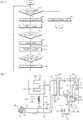
- FIG. 4 is a flowchart illustrating a method of operating a heat pump according to an embodiment of the present disclosure
- FIGs. 5 to 7C are views referred to for explanation of a method of operating a heat pump.
- the heat pump 10 may determine whether an outdoor temperature is less than a reference temperature. For example, the heat pump 10 may determine whether the sensing value of the outdoor temperature sensor is less than a reference temperature (e.g. -7°C) at which the efficiency of the heat pump 10 is lowered.
- a reference temperature e.g. -7°C
- the heat pump 10 may control the power of the boiler 500 to be turned off when the outdoor temperature is higher than the reference temperature, and control each component included in the heat pump 10 to provide the heating function
- the heat pump 10 may control the boiler 500 to be turned off so that the boiler 500 does not provide the heating function.
- the heat pump 10 may drive the compressor 120 to compress the refrigerant to provide the heating function, and control the refrigerant control valve 181 so that the refrigerant compressed by the compressor 120 is supplied to the water refrigerant heat exchanger 310 of the heat exchange device 300,.
- water flowing through the water passage 312 of the water refrigerant heat exchanger 310 may be heated.
- the heated water flowing through the water passage 312 may flow to the heating device 400 through the hot water-pipe 61 and the heating supply pipe 81.
- the heat pump 10 may control the hot water supply control valve 185 to be turned on so that water flows from the hot-water pipe 61 to the heating supply pipe 81
- the heat pump 10 may control the boiler valve 186 to be turned off so that water discharged from the heating device 400 to the heating recovery pipe 82 is not supplied to the boiler 500.
- the heat pump 10 may control power of the boiler 500 to be turned on, and control each component included in the heat pump 10 to stop providing the heating function through the heat pump 10.
- the heat pump 10 may control the power of the boiler 500 to be turned on so that the heating function may be provided through the boiler 500.
- the heat pump 10 may stop the operation of the compressor 120 and may control the refrigerant control valve 181 so that the refrigerant compressed by the compressor 120 is not supplied to the water refrigerant heat exchanger 310 of the heat exchange device 300.
- the heat pump 10 may control the hot water supply control valve 185 to be turned off so that water does not flow from the hot-water pipe 61 to the heating supply pipe 81, and the water flows to the cold-water pipe 71 through the bypass pipe 91.
- the heat pump 10 may control the boiler valve 186 to be turned on so that water discharged from the heating device 400 to the heating recovery pipe 82 is supplied to the boiler 500.
- the recovery pump 320 may operate so that water circulates through the water refrigerant heat exchanger 310 to prevent freezing even when the heating function through the heat pump 10 is stopped.
- the heat pump 10 may calculate a rate of change of water temperature based on the sensing value of the temperature sensor 190.
- the heat pump 10 may calculate the rate of change of the water temperature for a predetermined time (e.g. 5 minutes) after the heating function is stopped. In this case, the heat pump 10 may monitor the rate of change of the water temperature by repeatedly calculating and updating the rate of change of the water temperature.
- the heat pump 10 may determine whether the rate of change of the water temperature is less than a first reference rate of change.
- the first reference rate of change may mean a minimum degree at which the temperature of water flowing through the heating pipes changes when the boiler 500 provides the heating function.
- the first reference rate of change may be 0°C/min in which the temperature of water flowing through the heating pipe is constant for a predetermined time (e.g. 5 minutes).
- the heat pump 10 may determine that the boiler 500 provides the heating function when the rate of change of the water temperature is greater than or equal to the first reference rate of change (e.g. 0°C/min), and operate the operation S410. For example, even after the heating function by the heat pump 10 is stopped, the heat pump 10 may determine that the boiler 500 provides the heating function when the temperature of water flowing through the heating pipes is increased or maintained constant.
- the first reference rate of change e.g. 0°C/min
- the heat pump 10 may determine that the boiler 500 does not provide the heating function when the rate of change of the water temperature is less than the first reference rate of change (e.g. 0°C/min), and control the each component included in the heat pump 10 to provide the heating function.
- the first reference rate of change e.g. 0°C/min
- the heat pump 10 may determine that the boiler 500 has stopped providing the heating function in order to provide the hot water supply function according to the demand for hot water supply.
- the heat pump 10 may drive the compressor 120 to compress the refrigerant, control the refrigerant control valve 181 so that the refrigerant compressed by the compressor 120 is supplied to the water refrigerant heat exchanger 310 of the heat exchange device 300.
- the heat pump 10 may control the hot water supply control valve 185 to be turned on so that water flows from the hot-water pipe 61 to the heating supply pipe 81.
- the heat pump 10 may control the boiler valve 186 to be turned off so that water discharged from the heating device 400 to the heating recovery pipe 82 is not supplied to the boiler 500.
- the heat pump 10 may calculate the rate of change of the water temperature based on the sensing value of the temperature sensor 190. For example, the heat pump 10 may calculate the rate of change of the water temperature for a predetermined time (e.g. 5 minutes) after the provision of the heating function is started. In this case, the heat pump 10 may monitor the rate of change of the water temperature by repeatedly calculating and updating the rate of change of the water temperature flowing through the heating pipes.
- a predetermined time e.g. 5 minutes
- the heat pump 10 may determine whether the rate of change of the water temperature exceeds a second reference rate of change greater than the first reference rate of change.
- the second reference rate of change may mean a maximum degree at which the temperature of water flowing through the heating pipes changes when the heat pump 10 provides the heating function.
- the heat pump 10 may determine that only the heat pump 10 provides the heating function, and operate the operation S470
- the heat pump 10 may determine that the boiler 500 provides the heating function again, and stop providing the heating function of the heat pump 10.
- FIG. 7A is a diagram showing a graph 701 of the temperature of water flowing through the hot-water pipe 61 and a graph 703 of the temperature of water flowing through the cold-water pipe 71.
- FIG. 7B is a diagram showing a graph 705 of heating capacity according to the operation of the heat pump 10.
- FIG. 7C is a diagram showing a graph 707 of the temperature of water flowing through the boiler supply pipe 83.
- the outdoor temperature is less than the reference temperature (e.g. -7°C) and only the boiler 500 provides the heating function
- the temperature of the water flowing through the hot-water pipe 61 and the cold-water pipe 71 is kept constant at 30° C. or less, and the heating capacity of the heat pump 10 is also maintained close to 0 kW.
- hot water of about 60° C. may flow through the boiler supply pipe 83 due to the heating function provided by the boiler 500.
- the heat pump 10 may control each component included in the heat pump 10 to provide the heating function.
- the heat pump 10 controls each component included in the heat pump 10 to provide the heating function, the temperature of the water flowing through the hot-water pipe 61 and the cold-water pipe 71 temporarily increases rapidly at t2 because the water flowing in the heating pipes is supplied to the heat exchange device 300.
- the boiler 500 provides the heating function again, and the temperature of the water flowing through the boiler supply pipe 83 increases again due to the hot water supplied from the boiler 500.
- hot water supplied from the boiler 500 and hot water supplied from the heat pump 10 may flow through the heating pipes, and the temperature of the water flowing through the heating pipes rapidly increases. Accordingly, it may be calculated that the rate of change of the water temperature exceeds the second reference rate of change (e.g. 2°C/min), and the heat pump 10 stops providing the heating function.
- the second reference rate of change e.g. 2°C/min
- the heat pump 10 may determine whether the boiler 500 provides the hot water supply function through the temperature sensor 190 arranged in the heating pipes and may provide the heating function through the heat pump 10 when the boiler 500 provides the hot water supply function, so that temporary interruption of the heating function can be prevented even if a separate hot water tank is not provided.
- the heat pump 10 can be interlocked with boilers of various manufacturer because the heat pump 10 may determine whether the boiler 500 provides the hot water supply function even if the heat pump 10 does not use a separate communication function.
Landscapes
- Engineering & Computer Science (AREA)
- Physics & Mathematics (AREA)
- Mechanical Engineering (AREA)
- Thermal Sciences (AREA)
- General Engineering & Computer Science (AREA)
- Chemical & Material Sciences (AREA)
- Combustion & Propulsion (AREA)
- Power Engineering (AREA)
- Heat-Pump Type And Storage Water Heaters (AREA)
- Steam Or Hot-Water Central Heating Systems (AREA)
Abstract
Description
- The present disclosure relates to a heat pump capable of providing a heating function and a hot water supply function in conjunction with a boiler and a method of operating the same.
- In general, a heat pump is a device that that transfer heat from a low temperature source to a high temperature source and vice versa and may include an outdoor unit including a compressor and an outdoor heat exchanger, and an indoor unit including an expansion valve and an indoor heat exchanger.
- The heat pump can be used for a heating function that increases an indoor temperature or a hot water supply function that provides hot water to a user by heating water through heat exchange of a refrigerant, so that the use of fossil fuels can be replaced.
- In the case of using the heat pump as a heat source for heating or hot water supply, when an outdoor temperature is lowered by a certain level or more, the efficiency is rapidly deteriorated, and the heating function or the hot water supply function may be insufficiently provided with only the heat pump. Therefore, in the related art, when the outdoor temperature is lowered by a certain level or more, the heat pump and the boiler interlock, and the boiler instead of the heat pump provides the heating function or the hot water supply function.
- On the other hand, in general, in consideration of the user's expectation that high-temperature hot water is provided quickly rather than rapidly increasing indoor temperature, both the heat pump and the boiler provide the hot water supply function prior to the heating function. In this case, while the outdoor temperature is lowered by more than a certain level and the boiler instead of the heat pump provides the heating function, if the boiler provides the hot water supply function due to the demand for hot water supply, there is a problem that the heating function is temporarily stopped and the indoor temperature is lowered. In addition, there is also a problem in that it is difficult for the heat pump to determine whether the boiler stops providing the heating function and provides the hot water supply function because heat pumps and boilers are mostly products of different manufacturers, and the operation status of one side is not monitored by the other.
- Conventionally, in order to solve this problem, a hot water tank is provided for storing water used for hot water supply, and water stored in the hot water tank is heated through the heat pump. Through this, the boiler continues to provide the heating function, and water stored in the hot water tank is used for hot water supply.
- However, even according to the conventional method, since the hot water tank must be separately provided to supply hot water, there is a problem in that price competitiveness is lowered due to an increase in installation cost. In addition, since it is necessary to provide the hot water supply function through the heat pump whose efficiency is reduced due to a low outdoor temperature, there is a problem that the efficiency of the heat pump is further reduced.
- It is an object of the present disclosure to solve the above and other problems.
- It is another object of the present disclosure to provide a heat pump that may determine whether the boiler provides a hot water supply function without communication with the boiler and provide a heating function while the boiler provides the hot water supply function, and method thereof.
- The object is solved by the features of the independent claims. Preferred embodiments are given in the dependent claims.
- A heat pump in accordance with an exemplary embodiment of the present disclosure for accomplishing the above and other objects may include a compressor configured to compress a refrigerant, a first temperature sensor disposed in heating pipes connected to a heating device for performing indoor heating and configured to sense a temperature of water flowing through the heating pipes, and a controller, wherein the controller is configured to determine whether a boiler provides a heating function based on a sensing value of the first temperature sensor.
- Preferably, the controller may be configured to control to operate the compressor when the boiler does not provide the heating function.
- In some or more embodiments, the heat pump may further comprise a second temperature sensor configured to sense an outdoor temperature.
- Preferably, the controller may be configured to determine whether the boiler provides the heating function based on the sensing value of the first temperature sensor.
- Preferably, the controller may be configured to determine whether the boiler provides the heating function based on the sensing value of the first temperature sensor when a sensing value of the second temperature sensor is less than a reference temperature.
- In some or more embodiments, the controller may be configured to control the compressor to stop the operation when the sensing value of the second temperature sensor is less than the reference temperature, and/or may control the compressor to operate when the sensing value of the second temperature sensor is higher than the reference temperature.
- In some or more embodiments, the controller may be configured to calculate a rate of change of the temperature of the water flowing through the heating pipes based on the sensing value of the first temperature sensor.
- Preferably, the controller may be configured to calculate a rate of change of the temperature of the water flowing through the heating pipes based on the sensing value of the first temperature sensor when the sensing value of the second temperature sensor is less than the reference temperature, and/or may determine whether the boiler provides the heating function based on the calculated rate of change of the temperature of the water.
- In some or more embodiments, the controller may be configured to determine that the boiler does not provide the heating function when the calculated rate of change of the temperature of the water is less than a first reference rate, and/or may determine that the boiler provides the heating function when the calculated rate of change of the temperature of the water exceeds a second reference rate greater than the first reference rate.
- In some or more embodiments, the heat pump may further comprise a water refrigerant heat exchanger configured to exchange heat with water and the refrigerant compressed by the compressor.
- In some or more embodiments, the heat pump may further comprise a first valve disposed between the heating pipes and a hot-water pipe through which water discharged from the water refrigerant heat exchanger flows.
- In some or more embodiments, the controller may be configured to control the first valve to be turned off so that water does not flow from the hot-water pipe to the heating pipes.
- In some or more embodiments, the heat pump may further comprise a bypass pipe connecting the first valve and a cold-water pipe through which water supplied to the water refrigerant heat exchanger flows.
- Preferably, the heating pipes may be respectively connected to the first valve and the boiler.
- Preferably, the water discharged from the water refrigerant heat exchanger and flowing through the hot-water pipe may flow through the bypass pipe when the first valve is turned off.
- Preferably, the heat pump may further comprise a second valve disposed in a boiler recovery pipe through which water supplied to the boiler flows.
- Preferably, the controller may be configured to control the second valve to be turned off so that water is not supplied to the boiler when the sensing value of the second temperature sensor is higher than the reference temperature, or when the sensing value of the second temperature sensor is less than the reference temperature and the boiler does not provide the heating function.
- Preferably, the cold-water pipe may be connected to the heating device so that water discharged from the heating device may flow through the cold-water pipe.
- Preferably, the boiler recovery pipe may be connected to the cold-water pipe.
- A method of a heat pump in accordance with an exemplary embodiment of the present disclosure for accomplishing the above and other objects may comprise determining whether a boiler provides a heating function based on a sensing value of a first temperature sensor, and operating a compressor compressing a refrigerant when the boiler does not provide the heating function, wherein the first temperature sensor is disposed in heating pipes connected to a heating device for performing indoor heating and configured to sense a temperature of water flowing through the heating pipes.
- In some or more embodiments, the determining whether the boiler provides the heating function may comprise determining whether the boiler provides the heating function based on the sensing value of the first temperature sensor when a sensing value of a second temperature sensor configured to sense an outdoor temperature is less than a reference temperature.
- In some or more embodiments, the method may further comprise stopping the operation of the compressor when the sensing value of the second temperature sensor is less than the reference temperature; and/ or operating the compressor when the sensing value of the second temperature sensor is higher than the reference temperature.
- In some or more embodiments, the determining whether the boiler provides the heating function may further comprise calculating rate of change of the temperature of the water flowing through the heating pipes based on the sensing value of the first temperature sensor when the sensing value of the second temperature sensor is less than the reference temperature; and/or determining whether the boiler provides the heating function based on the calculated rate of change of the temperature of the water.
- In some or more embodiments, the determining whether the boiler provides the heating function based on the calculated rate of change of the temperature of the water may comprise determining that the boiler does not provide the heating function when the calculated rate of change of the temperature of the water is less than a first reference rate; and/or determining that the boiler provides the heating function when the calculated rate of change of the temperature of the water exceeds a second reference rate greater than the first reference rate.
- The additional range of applicability of the present disclosure will become apparent from the following detailed description. However, because various changes and modifications will be clearly understood by those skilled in the art within the spirit and scope of the present disclosure, it should be understood that the detailed description and specific embodiments such as preferred embodiments of the present disclosure are merely given by way of example.
- The above and other objects, features and other advantages of the present disclosure will be more clearly understood from the following detailed description taken in conjunction with the accompanying drawings, in which:
-
FIG. 1 is a view schematically illustrating a heat pump according to an embodiment of the present disclosure. -
FIG. 2 is a block diagram of a system including a heat pump according to an embodiment of the present disclosure. -
FIG. 3 is a block diagram of a heat pump according to an embodiment of the present disclosure. -
FIG. 4 is a flowchart illustrating a method of operating a heat pump according to an embodiment of the present disclosure. -
FIGs. 5 to 7C are views referred to for explanation of a method of operating a heat pump. - Hereinafter, the present disclosure will be described in detail with reference to the accompanying drawings. In order to clearly and briefly describe the present disclosure, components that are irrelevant to the description will be omitted in the drawings. The same reference numerals are used throughout the drawings to designate the same or similar components.
- Terms "module" and "part" for elements used in the following description are given simply in view of the ease of the description, and do not carry any important meaning or role. Therefore, the "module" and the "part" may be used interchangeably.
- It should be understood that the terms "comprise", "include", "have", etc. when used in this specification, specify the presence of stated features, integers, steps, operations, elements, components, or combinations of them but do not preclude the presence or addition of one or more other features, integers, steps, operations, elements, components, or combinations thereof.
- It will be understood that, although the terms "first", "second", etc. may be used herein to describe various elements, these elements should not be limited by these terms. These terms are only used to distinguish one element from another element.
- Unless otherwise defined, all terms including technical and scientific terms used herein have the same meaning as commonly understood by one of ordinary skill in the art to which the present disclosure belongs. Further, terms defined in a common dictionary will not be interpreted in an idealized or overly formal sense unless expressly so defined herein.
- In the drawings, the thicknesses or the sizes of elements and graphs may be exaggerated, omitted or simplified to more clearly and conveniently illustrate the present disclosure.
-
FIG. 1 is a view schematically illustrating a heat pump, andFIG. 2 is a block diagram of a system including the heat pump according to an embodiment of the present disclosure. - Referring to
FIGs. 1 and 2 , theheat pump 10 may include anoutdoor unit 100, anindoor unit 200, and/or aheat exchange device 300 for exchanging heat between compressed refrigerant and water. - The heat pump system including the
heat pump 10 may further include aheating device 400 and/or aboiler 500 for performing indoor heating. - The
outdoor unit 100 may include acompressor 120 compressing a refrigerant, anaccumulator 110 disposed in asuction passage 25 of thecompressor 120 to prevent the liquid refrigerant from flowing into thecompressor 120, anoil separator 130 disposed in adischarge passage 27 of thecompressor 120 to separate the oil from the refrigerant and oil discharged from thecompressor 120 and recover it to thecompressor 120 and/or a switchingvalve 170 for selecting a refrigerant flow path for heating/cooling operation. - The
outdoor unit 100 may further include a plurality of sensors, valves, and the like. - The
outdoor unit 100 and theindoor unit 200 may includeheat exchangers 140 and 210,fans expansion mechanisms indoor unit 200 may receive compressed refrigerant from theoutdoor unit 100 and discharge hot air or cold air into the room. - The outdoor heat exchanger 140 may condense or evaporate a refrigerant. The outdoor heat exchanger 140 may be configured as a heat exchanger for performing heat exchange between outdoor air and a refrigerant, or be configured as a heat exchanger for performing heat exchange between cooling water and a refrigerant.
- For example, when the outdoor heat exchanger 140 is configured as a heat exchanger in which heat exchange between outdoor air and refrigerant is performed, the
outdoor fan 150 may be disposed on one side of the outdoor heat exchanger 140 and blow outdoor air to the outdoor heat exchanger 140 to promote heat dissipation of the refrigerant. Hereinafter, a case where the outdoor heat exchanger 140 is configured as an air refrigerant heat exchanger in which outdoor air and refrigerant heat exchange with each other is described as an example. - The outdoor heat exchanger 140 may be connected to the
indoor heat exchanger 210 and the heatexchanger connection pipe 20, and theexpansion mechanisms exchanger connection pipe 20. - The heat
exchanger connection pipe 32 may include an expansiondevice connection pipe 21 to which theoutdoor expansion device 160 and theindoor expansion device 230 are connected, an Outdoor heat exchanger-outdoor expansion device connection pipe (22) to which the outdoor heat exchanger 140 and theoutdoor expansion device 160 are connected, and an Indoor expansion device-indoor heat exchanger connection pipe (23) to which theindoor heat exchanger 210 and theindoor expansion device 230 are connected. - The
indoor heat exchanger 210 may be a heat exchanger that cools or heats a room through heat exchange between indoor air and a refrigerant. Theindoor fan 220 may be disposed on one side of theindoor heat exchanger 210 to blow indoor air to theindoor heat exchanger 210. - In the case of a cooling mode in which the
heat pump 10 cools the room through theindoor unit 200, theheat exchanger 210 may function as an evaporator since the refrigerant compressed by thecompressor 120 of theoutdoor unit 100 sequentially passes through the outdoor heat exchanger 140, theexpansion mechanisms indoor heat exchanger 210, and thecompressor 120. - On the other hand, in the case of the heating mode in which the
heat pump 10 heats the room through theindoor unit 200, theheat exchanger 210 may function as a condenser since the refrigerant compressed by thecompressor 120 of theoutdoor unit 100 sequentially passes through theindoor heat exchanger 210, theexpansion mechanisms compressor 120. - The switching
valve 170 may change the flow direction of the refrigerant so that the refrigerant flows in the order of thecompressor 120, the outdoor heat exchanger 140, and theindoor heat exchanger 210, or in the order of thecompressor 120, theindoor heat exchanger 210, and theoutdoor heat exchanger 210. - The switching
valve 170 may be connected to thecompressor 120 through thecompressor suction passage 25 and thecompressor discharge passage 27. The switchingvalve 170 may be connected to theindoor heat exchanger 210 through the indoor heatexchanger connection pipe 31. The switchingvalve 170 may be connected to the outdoor heat exchanger 140 through the outdoor heatexchanger connection pipe 32. - The
outdoor unit 100 may include arefrigerant control valve 181 capable of selectively supplying the refrigerant supplied from thecompressor discharge passage 27 to theheat exchange device 300 or the switchingvalve 170. When therefrigerant control valve 181 is configured as a three-way valve, therefrigerant control valve 181 may be disposed on thecompressor discharge passage 27, a heat exchangedevice supply passage 41 for supplying the refrigerant to theheat exchange device 300 may be branched from therefrigerant control valve 181. - The
outdoor unit 100 may further include an auxiliaryrefrigerant control valve 182. The auxiliaryrefrigerant control valve 182 may operate so that the refrigerant transferred from theheat exchange device 300 to theoutdoor unit 100 is supplied to the heatexchanger bypass passage 33 or to the switchingvalve 170. Therefrigerant control valve 181 may be configured as a three-way valve. - The
outdoor unit 100 may further include a heatexchanger bypass valve 183 disposed in the heatexchanger bypass passage 33 to regulate the flow of refrigerant, and a liquidrefrigerant valve 184 disposed between the heatexchanger bypass passage 33 and theindoor expansion mechanism 230 to regulate the flow of the refrigerant. - The heat
exchanger bypass valve 183 may be turned on when theheat pump 100 provides a heating function, and be turned off when theheat pump 100 performs an air conditioning function or simultaneous operation of the air conditioning function and the heating function. - The liquid
refrigerant valve 184 may be turned on when theheat pump 100 performs the air conditioning function or simultaneous operation of the air conditioning function and the heating function, and be turned off when providing the heating function. - The
heat exchange device 300 may receive compressed refrigerant from theoutdoor unit 100 through the heat exchangedevice supply passage 41, and deliver the refrigerant to theoutdoor unit 100 through the heat exchangedevice recovery passage 51. - The
heat exchange device 300 may include a waterrefrigerant heat exchanger 310 for exchanging heat with water and refrigerant supplied from theoutdoor unit 100. The waterrefrigerant heat exchanger 310 may be composed of a double tube heat exchanger in which therefrigerant passage 311 and thewater passage 312 are formed inside/outside with a heat transfer member interposed therebetween. The waterrefrigerant heat exchanger 310 may also be composed of a plate-type heat exchanger in which therefrigerant passage 311 and thewater passage 312 are alternately formed with a heat transfer member therebetween. Hereinafter, a case where the waterrefrigerant heat exchanger 310 is configured as a plate heat exchanger will be described as an example. - The
refrigerant passage 311 of the waterrefrigerant heat exchanger 310 may be connected to the heat exchangedevice supply passage 41 and the heat exchangedevice recovery passage 51. - The refrigerant supplied to the water
refrigerant heat exchanger 310 through the heatexchanger supply passage 41 may be heat-exchanged while flowing through therefrigerant passage 311 and be transferred to theoutdoor unit 100 through the heatexchanger recovery passage 51. - The
water passage 312 of the waterrefrigerant heat exchanger 310 may be connected to a hot-water pipe 61 through which water is discharged from the waterrefrigerant heat exchanger 310 and a cold-water pipe 71 through which water is supplied to the waterrefrigerant heat exchanger 310. - A
recovery pump 320 for pumping water circulating through the waterrefrigerant heat exchanger 310 may be disposed in the cold-water pipe 71. Therecovery pump 320 may operate to circulate water through the waterrefrigerant heat exchanger 310 even when the refrigerant is not supplied from theoutdoor unit 100 to theheat exchanger 300 to prevent freezing. - The
heating device 400 may include aheat dissipation tube 410, and heat the indoor floor using hot water flowing along theheat dissipation tube 410. Theheating device 400 may be connected to theheating supply pipe 81 and theheating recovery pipe 82. - Water supplied through the
heating supply pipe 81 may be heat-exchanged while flowing through theheat dissipation pipe 410, and be discharged through theheating recovery pipe 82. Theheating supply pipe 81, theheat dissipation pipe 410, and theheating recovery pipe 82 may be referred to as heating pipes. - The
heating supply pipe 81 may be connected to the hot-water pipe 61, and theheating recovery pipe 82 may be connected to the cold-water pipe 71. - The
heat pump 10 may further include atemperature sensor 190 disposed in the heating pipes and detect a temperature of water flowing through the heating pipes. For example, thetemperature sensor 190 may be disposed in theheating supply pipe 81 among the heating pipes to detect the temperature of water supplied to theheating device 400. - A hot water
supply control valve 185 may be disposed between theheating supply pipe 81 and the hot-water pipe 61. For example, when the hot watersupply control valve 185 is turned on, water may flow from the hot-water pipe 61 to theheating supply pipe 81. For example, when the hot watersupply control valve 185 is turned off, the flow of water between the hot-water pipe 61 and theheating supply pipe 81 may be blocked, so that water may not flow from the hot-water pipe 61 to theheating supply pipe 81. - When the hot water
supply control valve 185 is configured as a three-way valve, the hot watersupply control valve 185 may be connected to thebypass pipe 91 connected to the cold-water pipe 71. Water may flow from the hot-water pipe 61 to the cold-water pipe 71 when the hot watersupply control valve 185 is turned off. - The
boiler 500 may include acombustion heating unit 510 that heats water by burning fossil fuels, and boilerheat exchange unit 520 for heat exchange between water heated by thecombustion heating unit 510 and water supplied from the water supply (CW). For example, when theboiler 500 provides a hot water supply function, theboiler 500 may heat water through thecombustion heating unit 510 and transfer it to the boilerheat exchange unit 520, and water supplied from the water supply (CW) may be heated through heat exchange with water heated by thecombustion heating unit 510 and then supplied to the hotwater supply unit 600. - The
boiler 500 may further include aboiler pump 530 that pumps water circulating through theboiler 500. - The
boiler 500 may further include aboiler bypass valve 540. Theboiler bypass valve 540 may be configured as a three-way valve. For example, when theboiler 500 provides the heating function, theboiler bypass valve 540 may be controlled so that water heated by thecombustion heating unit 510 flows through theboiler supply pipe 83. For example, when theboiler 500 provides the hot water supply function, theboiler bypass valve 540 may operate to transfer water heated by thecombustion heating unit 510 to the boilerheat exchange unit 520. - The
boiler 500 may be connected to theheating supply pipe 81 and theheating recovery pipe 82 through theboiler supply pipe 83 and aboiler recovery pipe 84. For example, water heated in theboiler 500 may flow to theheating supply pipe 81 through theboiler supply pipe 83, and water discharged from theheating device 400 to theheating recovery pipe 82 may flow to theboiler 500 through theboiler recovery pipe 84. - The
heat pump 10 may further include aboiler valve 186 disposed in theboiler recovery pipe 84 to regulate the flow of water. For example, when theboiler 500 does not operate as theheat pump 10 provides the heating function, the flow of water flowing from theheating recovery pipe 82 to theboiler 500 may be blocked because of theboiler valve 186 turned off. For example, when theboiler 500 provides the heating function, theboiler valve 186 may be turned on, and water discharged from theheating device 400 to theheating recovery pipe 82 may be transferred to theboiler 500. - The
heat pump 10 may control theboiler 500 to be turned on or turned off. - The
heat pump 10 may turn on/off the power of theboiler 500 without performing communication with theboiler 500. For example, theheat pump 10 may transmit a signal to a component (e.g. a switch) that transmits a power signal to theboiler 500 to turn on/off the power of theboiler 500. - Even when the power of the
boiler 500 is turned off by theheat pump 10, the power of theboiler 500 may be turned on when the user requests the use of hot water, and theboiler 500 may supply hot water to the hotwater supply unit 600 by using the water heated through thecombustion heating unit 510. -
FIG. 3 is a block diagram of a heat pump according to an embodiment of the present disclosure. - Referring to
FIG. 3 , theheat pump 10 may include afan driving unit 11, acompressor driving unit 12, avalve unit 13, asensor unit 14 and/or acontroller 15. - The
fan driving unit 11 may drive at least one fan included in theheat pump 10. For example, thefan driving unit 11 may drive theoutdoor fan 150 and/or theindoor fan 220. - The
fan driving unit 11 may include a rectifier that rectifies and outputs AC power to DC power, a dc capacitor that stores the pulsating voltage from the rectifier, an inverter that includes a plurality of switching elements and converts DC power to 3-phase AC power at a predetermined frequency, and/or a motor that drives thefans - The
fan driving unit 11 may include components for driving theoutdoor fan 150 and theindoor fan 220, respectively. - The
compressor driving unit 12 may drive thecompressor 120. - The
compressor driving unit 12 may include a rectifier that rectifies and outputs AC power to DC power, a dc capacitor that stores the pulsating voltage from the rectifier, an inverter that includes a plurality of switching elements and converts DC power to 3-phase AC power at a predetermined frequency, and/or a compressor motor that drives thecompressor 120 according to the three-phase AC power output from the inverter. - The
valve unit 13 may include at least one valve. At least one valve included in thevalve unit 13 may operate under the control of thecontroller 15. For example, thevalve unit 13 may include the switchingvalve 170, the auxiliaryrefrigerant control valve 182, the heatexchanger bypass valve 183, the liquidrefrigerant valve 184, the hot watersupply control valve 185, and/or theboiler valve 186. - The
sensor unit 14 may include at least one sensor, and transmit data on a sensing value sensed through at least one sensor to thecontroller 15. At least one sensor included in thesensor unit 14 may be disposed inside theoutdoor unit 100 and/or theindoor unit 200. For example, thesensor unit 14 may include a heat exchanger temperature sensor disposed inside the outdoor heat exchanger 140 to detect condensation temperature or evaporation temperature, a pressure sensor to detect the pressure of gaseous refrigerant flowing through each pipe, and/or a pipe temperature sensor to detect a temperature of a fluid flowing through each pipe. - The
sensor unit 14 may include an indoor temperature sensor to detect an indoor temperature and/or an outdoor temperature sensor to detect an outdoor temperature. For example, the outdoor temperature sensor may be disposed in theoutdoor unit 100, and the indoor temperature sensor may be disposed in theindoor unit 200. - The
sensor unit 14 may include atemperature sensor 190 disposed in the heating pipes connected to theheating device 400 to detect a temperature of water flowing through the heating pipes. - The
controller 15 may be connected to each component included in theheat pump 10 and control the overall operation of each component. Thecontroller 15 may transmit and receive data between components included in theheat pump 10. - The
controller 15 may be disposed in at least one of theindoor unit 200 and/or theheat exchange device 300 as well as theoutdoor unit 100. - The
controller 15 may include at least one processor and control the overall operation of theheat pump 10 using the processor. The processor may be a general processor such as a central processing unit (CPU). Of course, the processor may be a dedicated device such as an ASIC or another hardware-based processor. - The
controller 15 may control the operation of thefan driving unit 11. For example, thecontroller 15 may change the rotation speed of thefans fan driving unit 11. - The
controller 15 may control the operation of thecompressor driving unit 12. For example, thecontroller 15 may change the operating frequency of thecompressor 120 by changing the frequency of the three-phase AC power output to the compressor motor through operation control of thecompressor driving unit 12. - The
controller 15 may control an operation of at least one valve included in thevalve unit 13 according to a function provided by theheat pump 10. For example, when theheat pump 10 provides the heating function, thecontroller 15 may control the heatexchanger bypass valve 183 to be turned on and control the liquidrefrigerant valve 184 to be turned off. For example, when theheat pump 10 does not provide the heating function, thecontroller 15 may control the hot watersupply control valve 185 to be turned off so that water does not flow from the hot-water pipe 61 to theheating supply pipe 81. - The
controller 15 may control each component included in theheat pump 10 based on a sensing value of at least one sensor included in thesensor unit 14. - The
controller 15 may determine a function provided by theheat pump 10 based on a sensing value of the outdoor temperature sensor. For example, when the sensing value of the outdoor temperature sensor is less than the reference temperature, thecontroller 15 may stop the operation of thecompressor 120 so that theheat pump 10 does not provide the heating function. Here, the reference temperature may be a temperature of outdoor air (e.g. -7°C) at which the efficiency of theheat pump 10 is lowered. - The
controller 15 may determine an operating state of theboiler 500 based on the sensing value of thetemperature sensor 190. For example, thecontroller 15 may calculate a rate of change of water temperature based on the sensing value of thetemperature sensor 190, and determine whether theboiler 500 provides the heating function according to the calculated rate of change of the water temperature. In this case, thecontroller 15 may determine whether theboiler 500 provides the heating function when the sensing value of the outdoor temperature sensor is less than the reference temperature. - The
controller 15 may control power on/off of theboiler 500. For example, theheat pump 10 may further include a component (e.g. a switch) for transmitting a power signal to theboiler 500, and thecontroller 15 may transmit a signal to the component (e.g. a switch) to turn on/off the power of theboiler 500. -
FIG. 4 is a flowchart illustrating a method of operating a heat pump according to an embodiment of the present disclosure, andFIGs. 5 to 7C are views referred to for explanation of a method of operating a heat pump. - Referring to
FIG. 4 , in operation S410, theheat pump 10 may determine whether an outdoor temperature is less than a reference temperature. For example, theheat pump 10 may determine whether the sensing value of the outdoor temperature sensor is less than a reference temperature (e.g. -7°C) at which the efficiency of theheat pump 10 is lowered. - In operation S420, the
heat pump 10 may control the power of theboiler 500 to be turned off when the outdoor temperature is higher than the reference temperature, and control each component included in theheat pump 10 to provide the heating function - Referring to
FIG. 5 , when the outdoor temperature is higher than the reference temperature, theheat pump 10 may control theboiler 500 to be turned off so that theboiler 500 does not provide the heating function. - In addition, the
heat pump 10 may drive thecompressor 120 to compress the refrigerant to provide the heating function, and control therefrigerant control valve 181 so that the refrigerant compressed by thecompressor 120 is supplied to the waterrefrigerant heat exchanger 310 of theheat exchange device 300,. - In this case, due to heat exchange with the refrigerant flowing through the
refrigerant passage 311 of the waterrefrigerant heat exchanger 310, water flowing through thewater passage 312 of the waterrefrigerant heat exchanger 310 may be heated. In addition, the heated water flowing through thewater passage 312 may flow to theheating device 400 through the hot water-pipe 61 and theheating supply pipe 81. To this end, theheat pump 10 may control the hot watersupply control valve 185 to be turned on so that water flows from the hot-water pipe 61 to theheating supply pipe 81 - The
heat pump 10 may control theboiler valve 186 to be turned off so that water discharged from theheating device 400 to theheating recovery pipe 82 is not supplied to theboiler 500. - Referring to
FIG. 4 , in operation S430, when the outdoor temperature is less than the reference temperature, theheat pump 10 may control power of theboiler 500 to be turned on, and control each component included in theheat pump 10 to stop providing the heating function through theheat pump 10. - Referring to
FIG. 6A , when the outdoor temperature is less than the reference temperature, theheat pump 10 may control the power of theboiler 500 to be turned on so that the heating function may be provided through theboiler 500. - In addition, the
heat pump 10 may stop the operation of thecompressor 120 and may control therefrigerant control valve 181 so that the refrigerant compressed by thecompressor 120 is not supplied to the waterrefrigerant heat exchanger 310 of theheat exchange device 300. - In addition, the
heat pump 10 may control the hot watersupply control valve 185 to be turned off so that water does not flow from the hot-water pipe 61 to theheating supply pipe 81, and the water flows to the cold-water pipe 71 through thebypass pipe 91. - In addition, the
heat pump 10 may control theboiler valve 186 to be turned on so that water discharged from theheating device 400 to theheating recovery pipe 82 is supplied to theboiler 500. - The
recovery pump 320 may operate so that water circulates through the waterrefrigerant heat exchanger 310 to prevent freezing even when the heating function through theheat pump 10 is stopped. - Referring to
FIG. 4 , in operation S440, theheat pump 10 may calculate a rate of change of water temperature based on the sensing value of thetemperature sensor 190. - For example, the
heat pump 10 may calculate the rate of change of the water temperature for a predetermined time (e.g. 5 minutes) after the heating function is stopped. In this case, theheat pump 10 may monitor the rate of change of the water temperature by repeatedly calculating and updating the rate of change of the water temperature. - In operation S450, the
heat pump 10 may determine whether the rate of change of the water temperature is less than a first reference rate of change. The first reference rate of change may mean a minimum degree at which the temperature of water flowing through the heating pipes changes when theboiler 500 provides the heating function. For example, the first reference rate of change may be 0°C/min in which the temperature of water flowing through the heating pipe is constant for a predetermined time (e.g. 5 minutes). - The
heat pump 10 may determine that theboiler 500 provides the heating function when the rate of change of the water temperature is greater than or equal to the first reference rate of change (e.g. 0°C/min), and operate the operation S410. For example, even after the heating function by theheat pump 10 is stopped, theheat pump 10 may determine that theboiler 500 provides the heating function when the temperature of water flowing through the heating pipes is increased or maintained constant. - In operation S460, the
heat pump 10 may determine that theboiler 500 does not provide the heating function when the rate of change of the water temperature is less than the first reference rate of change (e.g. 0°C/min), and control the each component included in theheat pump 10 to provide the heating function. - Referring to
FIG. 6B , when theboiler 500 stops providing the heating function in order to provide the hot water supply function according to the demand for hot water supply, the temperature of the water flowing through the heating pipes may continue to decrease because theboiler 500 does not supply hot water to theheating device 400. In this case, when the rate of change of the water temperature is less than the first reference rate of change (e.g. 0°C/min), theheat pump 10 may determine that theboiler 500 has stopped providing the heating function in order to provide the hot water supply function according to the demand for hot water supply. - In addition, the
heat pump 10 may drive thecompressor 120 to compress the refrigerant, control therefrigerant control valve 181 so that the refrigerant compressed by thecompressor 120 is supplied to the waterrefrigerant heat exchanger 310 of theheat exchange device 300. - In addition, the
heat pump 10 may control the hot watersupply control valve 185 to be turned on so that water flows from the hot-water pipe 61 to theheating supply pipe 81. - The
heat pump 10 may control theboiler valve 186 to be turned off so that water discharged from theheating device 400 to theheating recovery pipe 82 is not supplied to theboiler 500. - Referring to
FIG. 4 , in operation S470, theheat pump 10 may calculate the rate of change of the water temperature based on the sensing value of thetemperature sensor 190. For example, theheat pump 10 may calculate the rate of change of the water temperature for a predetermined time (e.g. 5 minutes) after the provision of the heating function is started. In this case, theheat pump 10 may monitor the rate of change of the water temperature by repeatedly calculating and updating the rate of change of the water temperature flowing through the heating pipes. - In operation S480, the
heat pump 10 may determine whether the rate of change of the water temperature exceeds a second reference rate of change greater than the first reference rate of change. The second reference rate of change may mean a maximum degree at which the temperature of water flowing through the heating pipes changes when theheat pump 10 provides the heating function. - When the rate of change of the water temperature while the
heat pump 10 provides the heating function is less than or equal to the second reference rate of change (e.g. 2°C/min), theheat pump 10 may determine that only theheat pump 10 provides the heating function, and operate the operation S470 - For example, while the
heat pump 10 provides the heating function, when the temperature of water changes larger than the maximum temperature increase rate according to the operation of theheat pump 10, theheat pump 10 may determine that theboiler 500 provides the heating function again, and stop providing the heating function of theheat pump 10. -
FIG. 7A is a diagram showing agraph 701 of the temperature of water flowing through the hot-water pipe 61 and agraph 703 of the temperature of water flowing through the cold-water pipe 71.FIG. 7B is a diagram showing agraph 705 of heating capacity according to the operation of theheat pump 10.FIG. 7C is a diagram showing agraph 707 of the temperature of water flowing through theboiler supply pipe 83. - Referring to
FIGs. 7A to 7C , while the outdoor temperature is less than the reference temperature (e.g. -7°C) and only theboiler 500 provides the heating function, the temperature of the water flowing through the hot-water pipe 61 and the cold-water pipe 71 is kept constant at 30° C. or less, and the heating capacity of theheat pump 10 is also maintained close to 0 kW. - In addition, hot water of about 60° C. may flow through the
boiler supply pipe 83 due to the heating function provided by theboiler 500. - From t1 when the user requests hot water, hot water is not discharged from the
boiler 500 to theboiler supply pipe 83, and it can be confirmed that the temperature of the water flowing through theboiler supply pipe 83 continues to decrease from t1. - In this case, when hot water does not flow through the
boiler supply pipe 83, the temperature of the water flowing through the heating pipe continues to decrease so that the rate of change of the water temperature is calculated to be less than the first reference rate of change (e.g. 0°C/min), and theheat pump 10 may control each component included in theheat pump 10 to provide the heating function. - When the
heat pump 10 controls each component included in theheat pump 10 to provide the heating function, the temperature of the water flowing through the hot-water pipe 61 and the cold-water pipe 71 temporarily increases rapidly at t2 because the water flowing in the heating pipes is supplied to theheat exchange device 300. - From t1, due to the heating function of the
heat pump 10, the heating capacity of theheat pump 10 is maintained at a certain level, and the temperature of water flowing through the hot-water pipe 61 and the cold-water pipe 71 increases. In addition, due to heat exchange in theheating device 400, there is a difference between the temperature of water flowing through the hot-water pipe 61 and the temperature of water flowing through the cold-water pipe 71. - On the other hand, from t3 when the user's request for hot water supply ends, the
boiler 500 provides the heating function again, and the temperature of the water flowing through theboiler supply pipe 83 increases again due to the hot water supplied from theboiler 500. - In this case, hot water supplied from the
boiler 500 and hot water supplied from theheat pump 10 may flow through the heating pipes, and the temperature of the water flowing through the heating pipes rapidly increases. Accordingly, it may be calculated that the rate of change of the water temperature exceeds the second reference rate of change (e.g. 2°C/min), and theheat pump 10 stops providing the heating function. - When the heating function of the
heat pump 10 is stopped after t3, the temperature of the water flowing through the hot-water pipe 61 and the cold-water pipe 71 decreases again, and the heating capacity of theheat pump 10 is maintained close to 0 kW again. - According to the embodiments of the present disclosure, the
heat pump 10 may determine whether theboiler 500 provides the hot water supply function through thetemperature sensor 190 arranged in the heating pipes and may provide the heating function through theheat pump 10 when theboiler 500 provides the hot water supply function, so that temporary interruption of the heating function can be prevented even if a separate hot water tank is not provided. - In addition, according to the embodiments of the present disclosure, the
heat pump 10 can be interlocked with boilers of various manufacturer because theheat pump 10 may determine whether theboiler 500 provides the hot water supply function even if theheat pump 10 does not use a separate communication function. - In addition, according to the embodiments of the present disclosure, by temporarily using the
heat pump 10 while theboiler 500 provides the hot water supply function, it is possible to minimize a decrease in efficiency of theboiler 500 and theheat pump 10 while continuously providing the heating function desired by a user. - Since the accompanying drawings are merely for easily understanding embodiments disclosed herein, it should be understood that the technical idea disclosed herein is not limited by the accompanying drawings, and all changes, equivalents or substitutions are included in the technical scope of the present disclosure.
- Likewise, although operations are shown in a specific order in the drawings, it should not be understood that the operations are performed in the specific order shown in the drawings or in a sequential order so as to obtain desirable results, or all operations shown in the drawings are performed. In certain cases, multitasking and parallel processing may be advantageous.
- Although the present disclosure has been described with reference to specific embodiments shown in the drawings, it is apparent to those skilled in the art that the present description is not limited to those exemplary embodiments and is embodied in many forms without departing from the scope of the present disclosure, which is described in the following claims. These modifications should not be individually understood from the technical scope of the present disclosure.
Claims (15)
- A heat pump comprising:a compressor (120) configured to compress a refrigerant;a first temperature sensor (190) disposed in heating pipes (81) connected to a heating device (400) for performing indoor heating and configured to sense a temperature of water flowing through the heating pipes (81); anda controller (15) configured to:determine whether a boiler (500) provides a heating function based on a sensing value of the first temperature sensor (190), andcontrol the compressor (120) to operate depending on the operation of the boiler (500).
- The heat pump according to claim 1, wherein the controller (15) is configured to control the compressor (120) to operate when the boiler (500) does not provide a heating function.
- The heat pump according to claim 1 or 2, further comprising a second temperature sensor configured to sense an outdoor temperature, wherein the controller (15) is configured to determine whether the boiler (500) provides the heating function based on the sensing value of the first temperature sensor (190) when a sensing value of the second temperature sensor is less than a reference temperature.
- The heat pump according to claim 3, wherein the controller (15) is configured to:control the compressor (120) to stop the operation when the sensing value of the second temperature sensor is less than the reference temperature, and/orcontrol the compressor (120) to operate when the sensing value of the second temperature sensor is higher than the reference temperature.
- The heat pump according to claim 3 or 4, wherein the controller (15) is configured to:calculate a rate of change of the temperature of the water flowing through the heating pipes (81) based on the sensing value of the first temperature sensor (190) when the sensing value of the second temperature sensor is less than the reference temperature, anddetermine whether the boiler (500) provides the heating function based on the calculated rate of change of the temperature of the water.
- The heat pump according to claim 5, wherein the controller (15) is configured to:determine that the boiler (500) does not provide the heating function when the calculated rate of change of the temperature of the water is less than a first reference rate, anddetermine that the boiler (500) provides the heating function when the calculated rate of change of the temperature of the water exceeds a second reference rate greater than the first reference rate.
- The heat pump according to any one of the preceding claims, further comprising at least one of:a water refrigerant heat exchanger (310) configured to exchange heat with water and the refrigerant compressed by the compressor (120); anda first valve (185) disposed between the heating pipes (81) and a hot-water pipe (61) through which water discharged from the water refrigerant heat exchanger (310) flows,preferably the controller (15) is configured to control the first valve (185) to be turned off so that water does not flow from the hot-water pipe (61) to the heating pipes.
- The heat pump according to claim 7, further comprising a bypass pipe (91) connecting the first valve (185) and a cold-water pipe (71) through which water supplied to the water refrigerant heat exchanger (310) flows,wherein the heating pipes are respectively connected to the first valve (185) and the boiler (500), andwherein the water discharged from the water refrigerant heat exchanger (310) and flowing through the hot-water pipe (61) flows through the bypass pipe (91) when the first valve (185) is turned off.
- The heat pump according to to any one of the preceding claims 3-8, further comprising a second valve (186) disposed in a boiler recovery pipe (84) through which water supplied to the boiler (500) flows,
wherein the controller (15) is configured to control the second valve (186) to be turned off so that water is not supplied to the boiler (500) when the sensing value of the second temperature sensor is higher than the reference temperature, or when the sensing value of the second temperature sensor is less than the reference temperature and the boiler (500) does not provide the heating function. - The heat pump according to claim 9, wherein the cold-water pipe (71) is connected to the heating device (400) so that water discharged from the heating device (400) flows through the cold-water pipe 71, and
wherein the boiler recovery pipe (84) is connected to the cold-water pipe (71). - A method of a heat pump, the method comprising:determining whether a boiler (500) provides a heating function based on a sensing value of a first temperature sensor (190); andoperating a compressor (120) compressing a refrigerant when the boiler (500) does not provide the heating function,wherein the first temperature sensor (190) is disposed in heating pipes connected to a heating device (400) for performing indoor heating and configured to sense a temperature of water flowing through the heating pipes.
- The method of claim 11, wherein the determining whether the boiler (500) provides the heating function comprises determining whether the boiler (500) provides the heating function based on the sensing value of the first temperature sensor when a sensing value of a second temperature sensor configured to sense an outdoor temperature is less than a reference temperature.
- The method of claim 11 or 12, further comprising:stopping the operation of the compressor (120) when the sensing value of the second temperature sensor is less than the reference temperature; and/oroperating the compressor (120) when the sensing value of the second temperature sensor is higher than the reference temperature.
- The method of claim 12, wherein the determining whether the boiler (500) provides the heating function further comprises:calculating rate of change of the temperature of the water flowing through the heating pipes based on the sensing value of the first temperature sensor (190) when the sensing value of the second temperature sensor is less than the reference temperature; anddetermining whether the boiler (500) provides the heating function based on the calculated rate of change of the temperature of the water.
- The method of claim 14, wherein the determining whether the boiler (500) provides the heating function based on the calculated rate of change of the temperature of the water comprises:determining that the boiler (500) does not provide the heating function when the calculated rate of change of the temperature of the water is less than a first reference rate; anddetermining that the boiler (500) provides the heating function when the calculated rate of change of the temperature of the water exceeds a second reference rate greater than the first reference rate.
Applications Claiming Priority (1)
| Application Number | Priority Date | Filing Date | Title |
|---|---|---|---|
| KR1020200011332A KR102887235B1 (en) | 2020-01-30 | 2020-01-30 | Heat pump and method thereof |
Publications (2)
| Publication Number | Publication Date |
|---|---|
| EP3859216A1 true EP3859216A1 (en) | 2021-08-04 |
| EP3859216B1 EP3859216B1 (en) | 2024-12-11 |
Family
ID=74418263
Family Applications (1)
| Application Number | Title | Priority Date | Filing Date |
|---|---|---|---|
| EP21154288.1A Active EP3859216B1 (en) | 2020-01-30 | 2021-01-29 | Heat pump and method thereof |
Country Status (4)
| Country | Link |
|---|---|
| US (1) | US11619425B2 (en) |
| EP (1) | EP3859216B1 (en) |
| KR (1) | KR102887235B1 (en) |
| CN (1) | CN113203221A (en) |
Cited By (2)
| Publication number | Priority date | Publication date | Assignee | Title |
|---|---|---|---|---|
| CN115789811A (en) * | 2022-11-30 | 2023-03-14 | 青岛海尔空调器有限总公司 | Method and device for controlling heat pump system, heat pump system and storage medium |
| WO2024027144A1 (en) * | 2022-08-01 | 2024-02-08 | 青岛海信日立空调系统有限公司 | Hot water supply equipment |
Citations (4)
| Publication number | Priority date | Publication date | Assignee | Title |
|---|---|---|---|---|
| DE2659806A1 (en) * | 1976-12-16 | 1978-06-22 | Buderus Ag | Central heating with boiler and heat pump - has regulator with ambient air temp. sensors and changeover switch |
| EP2159495A1 (en) * | 2008-08-25 | 2010-03-03 | Honeywell Technologies Sarl | A controller for a temperature control system |
| KR20130135022A (en) * | 2012-05-30 | 2013-12-10 | 오텍캐리어 주식회사 | Hybrid heat pump boiler system |
| EP3252383A1 (en) * | 2016-05-31 | 2017-12-06 | Daikin Industries, Limited | Apparatus for space heating and warm water supply |
Family Cites Families (7)
| Publication number | Priority date | Publication date | Assignee | Title |
|---|---|---|---|---|
| EP2103890B1 (en) * | 2008-03-20 | 2013-09-04 | Daikin Industries, Ltd. | Heating and method for controlling the heating |
| KR101155006B1 (en) | 2010-08-17 | 2012-06-14 | 엘지전자 주식회사 | Heat pump and control method of the same |
| KR101203579B1 (en) * | 2010-11-05 | 2012-11-21 | 엘지전자 주식회사 | Speed heating apparatus with air conditioner and Control process of the same |
| ES2665566T3 (en) * | 2010-12-08 | 2018-04-26 | Daikin Europe N.V. | Heating |
| KR101436842B1 (en) * | 2012-12-26 | 2014-09-11 | 주식회사 경동나비엔 | Method for preventing freezing of heating pipe and hot-water pipe of boiler |
| CN104728979B (en) | 2015-03-27 | 2017-04-05 | 黄国和 | A kind of Renovation of air-conditioning system method and apparatus of application all-weather solar heat supply |
| CN106196258A (en) * | 2016-06-28 | 2016-12-07 | 四川自然道节能科技有限公司 | Heating water and saving energy system and control method thereof |
-
2020
- 2020-01-30 KR KR1020200011332A patent/KR102887235B1/en active Active
-
2021
- 2021-01-27 CN CN202110108414.6A patent/CN113203221A/en active Pending
- 2021-01-29 EP EP21154288.1A patent/EP3859216B1/en active Active
- 2021-01-29 US US17/162,785 patent/US11619425B2/en active Active
Patent Citations (4)
| Publication number | Priority date | Publication date | Assignee | Title |
|---|---|---|---|---|
| DE2659806A1 (en) * | 1976-12-16 | 1978-06-22 | Buderus Ag | Central heating with boiler and heat pump - has regulator with ambient air temp. sensors and changeover switch |
| EP2159495A1 (en) * | 2008-08-25 | 2010-03-03 | Honeywell Technologies Sarl | A controller for a temperature control system |
| KR20130135022A (en) * | 2012-05-30 | 2013-12-10 | 오텍캐리어 주식회사 | Hybrid heat pump boiler system |
| EP3252383A1 (en) * | 2016-05-31 | 2017-12-06 | Daikin Industries, Limited | Apparatus for space heating and warm water supply |
Cited By (2)
| Publication number | Priority date | Publication date | Assignee | Title |
|---|---|---|---|---|
| WO2024027144A1 (en) * | 2022-08-01 | 2024-02-08 | 青岛海信日立空调系统有限公司 | Hot water supply equipment |
| CN115789811A (en) * | 2022-11-30 | 2023-03-14 | 青岛海尔空调器有限总公司 | Method and device for controlling heat pump system, heat pump system and storage medium |
Also Published As
| Publication number | Publication date |
|---|---|
| US11619425B2 (en) | 2023-04-04 |
| KR20210097526A (en) | 2021-08-09 |
| CN113203221A (en) | 2021-08-03 |
| KR102887235B1 (en) | 2025-11-14 |
| US20210239370A1 (en) | 2021-08-05 |
| EP3859216B1 (en) | 2024-12-11 |
Similar Documents
| Publication | Publication Date | Title |
|---|---|---|
| JP5642207B2 (en) | Refrigeration cycle apparatus and refrigeration cycle control method | |
| JP6257801B2 (en) | Refrigeration cycle apparatus and refrigeration cycle apparatus abnormality detection system | |
| JP5748002B2 (en) | Heat pump type hot water supply system | |
| KR102815172B1 (en) | Heat pump and method thereof | |
| EP3071894B1 (en) | Air conditioner and method of controlling the same | |
| US20150040595A1 (en) | Refrigeration cycle apparatus | |
| CN113375365B (en) | Heat pump and operation method thereof | |
| CN104024764A (en) | Refrigeration apparatus | |
| US12235002B2 (en) | Air-conditioning system including a management section | |
| EP2522933B1 (en) | Heat storing apparatus having cascade cycle and control process of the same | |
| CN103998870A (en) | air conditioner | |
| EP3859216B1 (en) | Heat pump and method thereof | |
| JP3290251B2 (en) | Air conditioner | |
| KR101997458B1 (en) | Heat pump and method for controlling the same | |
| WO2021224962A1 (en) | Air conditioning device | |
| JP2009264714A (en) | Heat pump hot water system | |
| US20100043465A1 (en) | Heat pump system and method of controlling the same | |
| KR101488903B1 (en) | Heat storaging apparatus and Control process of the same | |
| EP4737813A1 (en) | Air conditioner, heat source module, indoor unit, and method for controlling air conditioner | |
| KR102140071B1 (en) | Air conditioner and method thereof | |
| KR20230102839A (en) | Heat pump and method thereof |
Legal Events
| Date | Code | Title | Description |
|---|---|---|---|
| PUAI | Public reference made under article 153(3) epc to a published international application that has entered the european phase |
Free format text: ORIGINAL CODE: 0009012 |
|
| STAA | Information on the status of an ep patent application or granted ep patent |
Free format text: STATUS: REQUEST FOR EXAMINATION WAS MADE |
|
| 17P | Request for examination filed |
Effective date: 20210129 |
|
| AK | Designated contracting states |
Kind code of ref document: A1 Designated state(s): AL AT BE BG CH CY CZ DE DK EE ES FI FR GB GR HR HU IE IS IT LI LT LU LV MC MK MT NL NO PL PT RO RS SE SI SK SM TR |
|
| RBV | Designated contracting states (corrected) |
Designated state(s): AL AT BE BG CH CY CZ DE DK EE ES FI FR GB GR HR HU IE IS IT LI LT LU LV MC MK MT NL NO PL PT RO RS SE SI SK SM TR |
|
| GRAP | Despatch of communication of intention to grant a patent |
Free format text: ORIGINAL CODE: EPIDOSNIGR1 |
|
| STAA | Information on the status of an ep patent application or granted ep patent |
Free format text: STATUS: GRANT OF PATENT IS INTENDED |
|
| RIC1 | Information provided on ipc code assigned before grant |
Ipc: F24D 19/10 20060101ALI20240618BHEP Ipc: F24D 15/04 20060101ALI20240618BHEP Ipc: F24D 12/02 20060101AFI20240618BHEP |
|
| INTG | Intention to grant announced |
Effective date: 20240711 |
|
| GRAS | Grant fee paid |
Free format text: ORIGINAL CODE: EPIDOSNIGR3 |
|
| GRAA | (expected) grant |
Free format text: ORIGINAL CODE: 0009210 |
|
| STAA | Information on the status of an ep patent application or granted ep patent |
Free format text: STATUS: THE PATENT HAS BEEN GRANTED |
|
| AK | Designated contracting states |
Kind code of ref document: B1 Designated state(s): AL AT BE BG CH CY CZ DE DK EE ES FI FR GB GR HR HU IE IS IT LI LT LU LV MC MK MT NL NO PL PT RO RS SE SI SK SM TR |
|
| REG | Reference to a national code |
Ref country code: GB Ref legal event code: FG4D |
|
| REG | Reference to a national code |
Ref country code: CH Ref legal event code: EP |
|
| REG | Reference to a national code |
Ref country code: DE Ref legal event code: R096 Ref document number: 602021023101 Country of ref document: DE |
|
| REG | Reference to a national code |
Ref country code: IE Ref legal event code: FG4D |
|
| REG | Reference to a national code |
Ref country code: LT Ref legal event code: MG9D |
|
| PG25 | Lapsed in a contracting state [announced via postgrant information from national office to epo] |
Ref country code: HR Free format text: LAPSE BECAUSE OF FAILURE TO SUBMIT A TRANSLATION OF THE DESCRIPTION OR TO PAY THE FEE WITHIN THE PRESCRIBED TIME-LIMIT Effective date: 20241211 |
|
| PG25 | Lapsed in a contracting state [announced via postgrant information from national office to epo] |
Ref country code: FI Free format text: LAPSE BECAUSE OF FAILURE TO SUBMIT A TRANSLATION OF THE DESCRIPTION OR TO PAY THE FEE WITHIN THE PRESCRIBED TIME-LIMIT Effective date: 20241211 |
|
| PG25 | Lapsed in a contracting state [announced via postgrant information from national office to epo] |
Ref country code: BG Free format text: LAPSE BECAUSE OF FAILURE TO SUBMIT A TRANSLATION OF THE DESCRIPTION OR TO PAY THE FEE WITHIN THE PRESCRIBED TIME-LIMIT Effective date: 20241211 |
|
| REG | Reference to a national code |
Ref country code: NL Ref legal event code: MP Effective date: 20241211 |
|
| PG25 | Lapsed in a contracting state [announced via postgrant information from national office to epo] |
Ref country code: ES Free format text: LAPSE BECAUSE OF FAILURE TO SUBMIT A TRANSLATION OF THE DESCRIPTION OR TO PAY THE FEE WITHIN THE PRESCRIBED TIME-LIMIT Effective date: 20241211 |
|
| PG25 | Lapsed in a contracting state [announced via postgrant information from national office to epo] |
Ref country code: NO Free format text: LAPSE BECAUSE OF FAILURE TO SUBMIT A TRANSLATION OF THE DESCRIPTION OR TO PAY THE FEE WITHIN THE PRESCRIBED TIME-LIMIT Effective date: 20250311 |
|
| PG25 | Lapsed in a contracting state [announced via postgrant information from national office to epo] |
Ref country code: LV Free format text: LAPSE BECAUSE OF FAILURE TO SUBMIT A TRANSLATION OF THE DESCRIPTION OR TO PAY THE FEE WITHIN THE PRESCRIBED TIME-LIMIT Effective date: 20241211 Ref country code: GR Free format text: LAPSE BECAUSE OF FAILURE TO SUBMIT A TRANSLATION OF THE DESCRIPTION OR TO PAY THE FEE WITHIN THE PRESCRIBED TIME-LIMIT Effective date: 20250312 |
|
| PG25 | Lapsed in a contracting state [announced via postgrant information from national office to epo] |
Ref country code: RS Free format text: LAPSE BECAUSE OF FAILURE TO SUBMIT A TRANSLATION OF THE DESCRIPTION OR TO PAY THE FEE WITHIN THE PRESCRIBED TIME-LIMIT Effective date: 20250311 |
|
| PG25 | Lapsed in a contracting state [announced via postgrant information from national office to epo] |
Ref country code: NL Free format text: LAPSE BECAUSE OF FAILURE TO SUBMIT A TRANSLATION OF THE DESCRIPTION OR TO PAY THE FEE WITHIN THE PRESCRIBED TIME-LIMIT Effective date: 20241211 |
|
| REG | Reference to a national code |
Ref country code: AT Ref legal event code: MK05 Ref document number: 1750646 Country of ref document: AT Kind code of ref document: T Effective date: 20241211 |
|
| PG25 | Lapsed in a contracting state [announced via postgrant information from national office to epo] |
Ref country code: SM Free format text: LAPSE BECAUSE OF FAILURE TO SUBMIT A TRANSLATION OF THE DESCRIPTION OR TO PAY THE FEE WITHIN THE PRESCRIBED TIME-LIMIT Effective date: 20241211 |
|
| PG25 | Lapsed in a contracting state [announced via postgrant information from national office to epo] |
Ref country code: PL Free format text: LAPSE BECAUSE OF FAILURE TO SUBMIT A TRANSLATION OF THE DESCRIPTION OR TO PAY THE FEE WITHIN THE PRESCRIBED TIME-LIMIT Effective date: 20241211 |
|
| PG25 | Lapsed in a contracting state [announced via postgrant information from national office to epo] |
Ref country code: IS Free format text: LAPSE BECAUSE OF FAILURE TO SUBMIT A TRANSLATION OF THE DESCRIPTION OR TO PAY THE FEE WITHIN THE PRESCRIBED TIME-LIMIT Effective date: 20250411 |
|
| PG25 | Lapsed in a contracting state [announced via postgrant information from national office to epo] |
Ref country code: PT Free format text: LAPSE BECAUSE OF FAILURE TO SUBMIT A TRANSLATION OF THE DESCRIPTION OR TO PAY THE FEE WITHIN THE PRESCRIBED TIME-LIMIT Effective date: 20250411 |
|
| PG25 | Lapsed in a contracting state [announced via postgrant information from national office to epo] |
Ref country code: EE Free format text: LAPSE BECAUSE OF FAILURE TO SUBMIT A TRANSLATION OF THE DESCRIPTION OR TO PAY THE FEE WITHIN THE PRESCRIBED TIME-LIMIT Effective date: 20241211 |
|
| PG25 | Lapsed in a contracting state [announced via postgrant information from national office to epo] |
Ref country code: AT Free format text: LAPSE BECAUSE OF FAILURE TO SUBMIT A TRANSLATION OF THE DESCRIPTION OR TO PAY THE FEE WITHIN THE PRESCRIBED TIME-LIMIT Effective date: 20241211 Ref country code: RO Free format text: LAPSE BECAUSE OF FAILURE TO SUBMIT A TRANSLATION OF THE DESCRIPTION OR TO PAY THE FEE WITHIN THE PRESCRIBED TIME-LIMIT Effective date: 20241211 |
|
| PG25 | Lapsed in a contracting state [announced via postgrant information from national office to epo] |
Ref country code: SK Free format text: LAPSE BECAUSE OF FAILURE TO SUBMIT A TRANSLATION OF THE DESCRIPTION OR TO PAY THE FEE WITHIN THE PRESCRIBED TIME-LIMIT Effective date: 20241211 |
|
| PG25 | Lapsed in a contracting state [announced via postgrant information from national office to epo] |
Ref country code: CZ Free format text: LAPSE BECAUSE OF FAILURE TO SUBMIT A TRANSLATION OF THE DESCRIPTION OR TO PAY THE FEE WITHIN THE PRESCRIBED TIME-LIMIT Effective date: 20241211 |
|
| REG | Reference to a national code |
Ref country code: CH Ref legal event code: PL |
|
| PG25 | Lapsed in a contracting state [announced via postgrant information from national office to epo] |
Ref country code: SE Free format text: LAPSE BECAUSE OF FAILURE TO SUBMIT A TRANSLATION OF THE DESCRIPTION OR TO PAY THE FEE WITHIN THE PRESCRIBED TIME-LIMIT Effective date: 20241211 |
|
| REG | Reference to a national code |
Ref country code: DE Ref legal event code: R097 Ref document number: 602021023101 Country of ref document: DE |
|
| PG25 | Lapsed in a contracting state [announced via postgrant information from national office to epo] |
Ref country code: LU Free format text: LAPSE BECAUSE OF NON-PAYMENT OF DUE FEES Effective date: 20250129 Ref country code: MC Free format text: LAPSE BECAUSE OF FAILURE TO SUBMIT A TRANSLATION OF THE DESCRIPTION OR TO PAY THE FEE WITHIN THE PRESCRIBED TIME-LIMIT Effective date: 20241211 |
|
| PG25 | Lapsed in a contracting state [announced via postgrant information from national office to epo] |
Ref country code: DK Free format text: LAPSE BECAUSE OF FAILURE TO SUBMIT A TRANSLATION OF THE DESCRIPTION OR TO PAY THE FEE WITHIN THE PRESCRIBED TIME-LIMIT Effective date: 20241211 |
|
| PG25 | Lapsed in a contracting state [announced via postgrant information from national office to epo] |
Ref country code: BE Free format text: LAPSE BECAUSE OF NON-PAYMENT OF DUE FEES Effective date: 20250131 |
|
| PLBE | No opposition filed within time limit |
Free format text: ORIGINAL CODE: 0009261 |
|
| STAA | Information on the status of an ep patent application or granted ep patent |
Free format text: STATUS: NO OPPOSITION FILED WITHIN TIME LIMIT |
|
| PG25 | Lapsed in a contracting state [announced via postgrant information from national office to epo] |
Ref country code: CH Free format text: LAPSE BECAUSE OF NON-PAYMENT OF DUE FEES Effective date: 20250131 |
|
| REG | Reference to a national code |
Ref country code: BE Ref legal event code: MM Effective date: 20250131 |
|
| 26N | No opposition filed |
Effective date: 20250912 |
|
| GBPC | Gb: european patent ceased through non-payment of renewal fee |
Effective date: 20250311 |
|
| PG25 | Lapsed in a contracting state [announced via postgrant information from national office to epo] |
Ref country code: GB Free format text: LAPSE BECAUSE OF NON-PAYMENT OF DUE FEES Effective date: 20250311 |
|
| PG25 | Lapsed in a contracting state [announced via postgrant information from national office to epo] |
Ref country code: FR Free format text: LAPSE BECAUSE OF NON-PAYMENT OF DUE FEES Effective date: 20250211 |
|
| PG25 | Lapsed in a contracting state [announced via postgrant information from national office to epo] |
Ref country code: IE Free format text: LAPSE BECAUSE OF NON-PAYMENT OF DUE FEES Effective date: 20250129 |
|
| PGFP | Annual fee paid to national office [announced via postgrant information from national office to epo] |
Ref country code: DE Payment date: 20251208 Year of fee payment: 6 |
|
| PGFP | Annual fee paid to national office [announced via postgrant information from national office to epo] |
Ref country code: IT Payment date: 20251209 Year of fee payment: 6 |