EP3859212A1 - Combustor shell with shaped impingement holes - Google Patents
Combustor shell with shaped impingement holes Download PDFInfo
- Publication number
- EP3859212A1 EP3859212A1 EP21154373.1A EP21154373A EP3859212A1 EP 3859212 A1 EP3859212 A1 EP 3859212A1 EP 21154373 A EP21154373 A EP 21154373A EP 3859212 A1 EP3859212 A1 EP 3859212A1
- Authority
- EP
- European Patent Office
- Prior art keywords
- combustor
- impingement
- impingement aperture
- heat shield
- aperture
- Prior art date
- Legal status (The legal status is an assumption and is not a legal conclusion. Google has not performed a legal analysis and makes no representation as to the accuracy of the status listed.)
- Granted
Links
Images



Classifications
-
- F—MECHANICAL ENGINEERING; LIGHTING; HEATING; WEAPONS; BLASTING
- F23—COMBUSTION APPARATUS; COMBUSTION PROCESSES
- F23R—GENERATING COMBUSTION PRODUCTS OF HIGH PRESSURE OR HIGH VELOCITY, e.g. GAS-TURBINE COMBUSTION CHAMBERS
- F23R3/00—Continuous combustion chambers using liquid or gaseous fuel
- F23R3/002—Wall structures
-
- F—MECHANICAL ENGINEERING; LIGHTING; HEATING; WEAPONS; BLASTING
- F23—COMBUSTION APPARATUS; COMBUSTION PROCESSES
- F23R—GENERATING COMBUSTION PRODUCTS OF HIGH PRESSURE OR HIGH VELOCITY, e.g. GAS-TURBINE COMBUSTION CHAMBERS
- F23R3/00—Continuous combustion chambers using liquid or gaseous fuel
- F23R3/005—Combined with pressure or heat exchangers
-
- F—MECHANICAL ENGINEERING; LIGHTING; HEATING; WEAPONS; BLASTING
- F05—INDEXING SCHEMES RELATING TO ENGINES OR PUMPS IN VARIOUS SUBCLASSES OF CLASSES F01-F04
- F05D—INDEXING SCHEME FOR ASPECTS RELATING TO NON-POSITIVE-DISPLACEMENT MACHINES OR ENGINES, GAS-TURBINES OR JET-PROPULSION PLANTS
- F05D2260/00—Function
- F05D2260/20—Heat transfer, e.g. cooling
- F05D2260/201—Heat transfer, e.g. cooling by impingement of a fluid
-
- F—MECHANICAL ENGINEERING; LIGHTING; HEATING; WEAPONS; BLASTING
- F23—COMBUSTION APPARATUS; COMBUSTION PROCESSES
- F23R—GENERATING COMBUSTION PRODUCTS OF HIGH PRESSURE OR HIGH VELOCITY, e.g. GAS-TURBINE COMBUSTION CHAMBERS
- F23R2900/00—Special features of, or arrangements for continuous combustion chambers; Combustion processes therefor
- F23R2900/00004—Preventing formation of deposits on surfaces of gas turbine components, e.g. coke deposits
-
- F—MECHANICAL ENGINEERING; LIGHTING; HEATING; WEAPONS; BLASTING
- F23—COMBUSTION APPARATUS; COMBUSTION PROCESSES
- F23R—GENERATING COMBUSTION PRODUCTS OF HIGH PRESSURE OR HIGH VELOCITY, e.g. GAS-TURBINE COMBUSTION CHAMBERS
- F23R2900/00—Special features of, or arrangements for continuous combustion chambers; Combustion processes therefor
- F23R2900/03044—Impingement cooled combustion chamber walls or subassemblies
-
- Y—GENERAL TAGGING OF NEW TECHNOLOGICAL DEVELOPMENTS; GENERAL TAGGING OF CROSS-SECTIONAL TECHNOLOGIES SPANNING OVER SEVERAL SECTIONS OF THE IPC; TECHNICAL SUBJECTS COVERED BY FORMER USPC CROSS-REFERENCE ART COLLECTIONS [XRACs] AND DIGESTS
- Y02—TECHNOLOGIES OR APPLICATIONS FOR MITIGATION OR ADAPTATION AGAINST CLIMATE CHANGE
- Y02T—CLIMATE CHANGE MITIGATION TECHNOLOGIES RELATED TO TRANSPORTATION
- Y02T50/00—Aeronautics or air transport
- Y02T50/60—Efficient propulsion technologies, e.g. for aircraft
Definitions
- the subject matter disclosed herein generally relates to gas turbine engines and, more particularly, to a method and apparatus for mitigating heat in cooling surfaces of gas turbine engines.
- a combustor of a gas turbine engine may be configured to burn fuel in a combustion area.
- Such configurations may place substantial heat load on the structure of the combustor (e.g., heat shield panels, combustor shells, etc.).
- heat loads may dictate that special consideration is given to structures, which may be configured as heat shields or panels, and to the cooling of such structures to protect these structures. Excess temperatures at these structures may lead to oxidation, cracking, and high thermal stresses of the heat shields panels.
- a combustor for use in a gas turbine engine, the combustor comprising a heat shield panel having a first surface and a second surface opposite the first surface of the heat shield panel; and a combustor shell having an inner surface and an outer surface opposite the inner surface, the inner surface of the combustor shell and the second surface of the heat shield panel being in a facing spaced relationship defining an impingement cavity therebetween, wherein the combustor shell further includes an impingement aperture that has a nonaxisymmetric shape, the impingement aperture extending from the outer surface to the inner surface through the combustor shell.
- the nonaxisymmetric shape of the impingement aperture may extend from the outer surface to the inner surface through the combustor shell.
- the impingement aperture may have only one wall that forms the impingement aperture by extending from the outer surface to the inner surface through the combustor shell.
- the impingement aperture may have two or more walls that forms the impingement aperture by extending from the outer surface to the inner surface through the combustor shell.
- the impingement aperture may be crescent-shaped.
- the impingement aperture may be star-shaped.
- the impingement aperture may be comma-shaped.
- the impingement aperture may be oval-shaped.
- the nonaxisymmetric shape of the impingement aperture may be composed of two or more intersecting shapes.
- the two or more intersecting shapes may be circles.
- the two or more intersecting shapes may be aligned in an arc.
- a gas turbine engine comprising a combustor section; and the combustor of the first aspect housed within the combustor section.
- the combustor may optionally comprise any of the additional features above.
- a gas turbine engine comprising a combustor section and a combustor housed within the combustor section, the combustor comprising a heat shield panel having a first surface and a second surface opposite the first surface of the heat shield panel; and a combustor shell having an inner surface and an outer surface opposite the inner surface, the inner surface of the combustor shell and the second surface of the heat shield panel being in a facing spaced relationship defining an impingement cavity therebetween, wherein the combustor shell further comprises an impingement aperture that has a nonaxisymmetric shape, the impingement aperture extending from the outer surface to the inner surface through the combustor shell.
- the nonaxisymmetric shape of the impingement aperture may extend from the outer surface to the inner surface through the combustor shell.
- the impingement aperture may have only one wall that forms the impingement aperture by extending from the outer surface to the inner surface through the combustor shell.
- the impingement aperture may have two or more walls that form the impingement aperture by extending from the outer surface to the inner surface through the combustor shell.
- the impingement aperture may be crescent-shaped.
- the impingement aperture may be star-shaped.
- the impingement aperture may be comma-shaped.
- the impingement aperture may be oval-shaped.
- the nonaxisymmetric shape of the impingement aperture may be composed of two or more intersecting shapes.
- FIG. 1 schematically illustrates a gas turbine engine 20.
- the gas turbine engine 20 is disclosed herein as a two-spool turbofan that generally incorporates a fan section 22, a compressor section 24, a combustor section 26 and a turbine section 28.
- the fan section 22 drives air along a bypass flow path B in a bypass duct, while the compressor section 24 drives air along a core flow path C for compression and communication into the combustor section 26 then expansion through the turbine section 28.
- FIG. 1 schematically illustrates a gas turbine engine 20.
- the gas turbine engine 20 is disclosed herein as a two-spool turbofan that generally incorporates a fan section 22, a compressor section 24, a combustor section 26 and a turbine section 28.
- the fan section 22 drives air along a bypass flow path B in a bypass duct
- the compressor section 24 drives air along a core flow path C for compression and communication into the combustor section 26 then expansion through the turbine section 28.
- the exemplary engine 20 generally includes a low speed spool 30 and a high speed spool 32 mounted for rotation about an engine central longitudinal axis A relative to an engine static structure 36 via several bearing systems 38. It should be understood that various bearing systems 38 at various locations may alternatively or additionally be provided, and the location of bearing systems 38 may be varied as appropriate to the application.
- the low speed spool 30 generally includes an inner shaft 40 that interconnects a fan 42, a low pressure compressor 44 and a low pressure turbine 46.
- the inner shaft 40 is connected to the fan 42 through a speed change mechanism, which in exemplary gas turbine engine 20 is illustrated as a geared architecture 48 to drive the fan 42 at a lower speed than the low speed spool 30.
- the high speed spool 32 includes an outer shaft 50 that interconnects a high pressure compressor 52 and high pressure turbine 54.
- a combustor 300 is arranged in exemplary gas turbine 20 between the high pressure compressor 52 and the high pressure turbine 54.
- An engine static structure 36 is arranged generally between the high pressure turbine 54 and the low pressure turbine 46.
- the engine static structure 36 further supports bearing systems 38 in the turbine section 28.
- the inner shaft 40 and the outer shaft 50 are concentric and rotate via bearing systems 38 about the engine central longitudinal axis A which is collinear with their longitudinal axes.
- each of the positions of the fan section 22, compressor section 24, combustor section 26, turbine section 28, and fan drive gear system 48 may be varied.
- gear system 48 may be located aft of combustor section 26 or even aft of turbine section 28, and fan section 22 may be positioned forward or aft of the location of gear system 48.
- the engine 20 in one example is a high-bypass geared aircraft engine.
- the engine 20 bypass ratio is greater than about six (6), with an example embodiment being greater than about ten (10)
- the geared architecture 48 is an epicyclic gear train, such as a planetary gear system or other gear system, with a gear reduction ratio of greater than about 2.3 and the low pressure turbine 46 has a pressure ratio that is greater than about five.
- the engine 20 bypass ratio is greater than about ten (10:1)
- the fan diameter is significantly larger than that of the low pressure compressor 44
- the low pressure turbine 46 has a pressure ratio that is greater than about five (5:1).
- Low pressure turbine 46 pressure ratio is pressure measured prior to inlet of low pressure turbine 46 as related to the pressure at the outlet of the low pressure turbine 46 prior to an exhaust nozzle.
- the geared architecture 48 may be an epicyclic gear train, such as a planetary gear system or other gear system, with a gear reduction ratio of greater than about 2.3:1. It should be understood, however, that the above parameters are only exemplary of one embodiment of a geared architecture engine and that the present disclosure is applicable to other gas turbine engines including direct drive turbofans.
- the fan section 22 of the engine 20 is designed for a particular flight condition--typically cruise at about 0.8 Mach and about 35,000 feet (10,668 meters).
- 'TSFC' Thrust Specific Fuel Consumption
- Low fan pressure ratio is the pressure ratio across the fan blade alone, without a Fan Exit Guide Vane (“FEGV”) system.
- the low fan pressure ratio as disclosed herein according to one non-limiting embodiment is less than about 1.45.
- Low corrected fan tip speed is the actual fan tip speed in ft/sec divided by an industry standard temperature correction of [(Tram °R)/(518.7 °R)] 0.5 .
- the "Low corrected fan tip speed” as disclosed herein according to one non-limiting embodiment is less than about 1150 ft/second (350.5 m/sec).
- the combustor 300 of FIG. 2 is an impingement film float wall combustor. It is understood that while an impingement film float wall combustor is utilized for exemplary illustration, the embodiments disclosed herein may be applicable to other types of combustors for gas turbine engines including but not limited to double pass liner combustors, float wall combustors, and combustors with single wall liners.
- a combustor 300 defines a combustion chamber 302.
- the combustion chamber 302 includes a combustion area 370 within the combustion chamber 302.
- the combustor 300 includes an inlet 306 and an outlet 308 through which air may pass.
- the air may be supplied to the combustor 300 by a pre-diffuser 110. Air may also enter the combustion chamber 302 through other holes in the combustor 300 including but not limited to quench holes 310, as seen in FIG. 2 .
- Compressor air is supplied from the compressor section 24 into a pre-diffuser 110, which then directs the airflow toward the combustor 300.
- the combustor 300 and the pre-diffuser 110 are separated by a dump region 113 from which the flow separates into an inner shroud 114 and an outer shroud 116.
- a portion of the air may flow into the combustor inlet 306, a portion may flow into the inner shroud 114, and a portion may flow into the outer shroud 116.
- the air from the inner shroud 114 and the outer shroud 116 may then enter the combustion chamber 302 by means of one or more impingement apertures 307 in the combustor shell 600 and one or more effusion apertures 309 in the heat shield panel 400, as shown in FIGS. 2 and 3 .
- the impingement apertures 307 and effusion apertures 309 may include nozzles, holes, etc.
- the air may then exit the combustion chamber 302 through the combustor outlet 308.
- fuel may be injected into the combustion chamber 302 through the primary and/or secondary orifices of a fuel injector 320 and a pilot nozzle 322, which may be atomized and mixed with air, and then ignited and burned within the combustion chamber 302.
- the diffuser case 124 defines the inner shroud 114 and the outer shroud 116.
- the combustor 300 is housed within the diffuser case 124 between the inner shroud 114 and the outer shroud 116.
- the combustor 300 includes multiple heat shield panels 400 that are attached to one or more combustor shells 600 (See FIG. 3 ).
- the heat shield panels 400 may be arranged parallel to the combustor shell 600.
- the combustor shell 600 includes a radially inward combustor shell 600a and a radially outward combustor shell 600b defined the combustion chamber 302 therebetween.
- the combustor shell 600 also includes a forward combustor shell 600c extending between the radially inward combustor shell 600a and the radially outward combustor shell 600b.
- the forward combustor shell 600c further bounds the combustion chamber 302 on a forward end 300a of the combustor 300.
- the radially inward combustor shell 600a and the radially outward combustor shell 600b extend circumferentially around the longitudinal engine axis A.
- the radially inward combustor shell 600a is located radially inward from the radially outward combustor shell 600b.
- the heat shield panels 400 can be removably mounted to the combustor shell 600 by one or more attachment mechanisms 332.
- the attachment mechanism 332 may be integrally formed with a respective heat shield panel 400, although other configurations are possible.
- the attachment mechanism 332 may be a threaded mounting stud or other structure that may extend from the respective heat shield panel 400 through the interior surface to a receiving portion or aperture of the combustor shell 600 such that the heat shield panel 400 may be attached to the combustor shell 600 and held in place.
- the heat shield panels 400 partially enclose a combustion area 370 within the combustion chamber 302 of the combustor 300.
- a heat shield panel 400 and combustor shell 600 of the combustor 300 (see FIG. 2 ) that may be used within the gas turbine engine 20 (see FIG. 1 ).
- Impingement and convective cooling of heat shield panels 400 of the combustor 300 may be used to help cool the combustor 300.
- Convective cooling may be achieved by air that is channeled between the heat shield panels 400 and a combustor shell 600 of the combustor 300.
- Impingement cooling may be a process of directing relatively cool air from a location exterior to the combustor 300 toward a back or underside of the heat shield panels 400.
- heat shield panels 400 are utilized to face the hot products of combustion within a combustion chamber 302 and protect the combustor shell 600 of the combustor 300.
- the heat shield panels 400 may be supplied with cooling air through the impingement apertures 307 and other dilution passages which deliver a high volume of cooling air into a hot flow path.
- the cooling air may be air from the compressor of the gas turbine engine 20.
- the cooling air may impinge upon a back side (i.e., second surface 420) of the heat shield panel 400 that faces the combustor shell 600 inside the combustor 300.
- the cooling air may contain particulates, which may build up on the heat shield panels 400 overtime, thus reducing the cooling ability of the cooling air.
- Embodiments disclosed herein seek to address particulate adherence to the heat shield panels 400 in order to maintain the cooling ability of the cooling air.
- the heat shield panel 400 and the combustor shell 600 are in a facing spaced relationship.
- the heat shield panel 400 includes a first surface 410 oriented towards the combustion area 370 of the combustion chamber 302 and a second surface 420 opposite the first surface 410 oriented towards the combustor shell 600.
- the combustor shell 600 has an inner surface 610 and an outer surface 620 opposite the inner surface 610.
- the inner surface 610 is oriented toward the heat shield panel 400.
- the outer surface 620 is oriented outward from the combustor 300 proximate the inner shroud 114 and the outer shroud 116.
- the combustor shell 600 includes a plurality of impingement apertures 307 configured to allow airflow 590 from the inner shroud 114 and the outer shroud 116 to enter an impingement cavity 390 located between the combustor shell 600 and the heat shield panel 400.
- Each of the impingement apertures 307 extend from the outer surface 620 to the inner surface 610 through the combustor shell 600.
- Each of the impingement apertures 307 fluidly connects the impingement cavity 390 to at least one of the inner shroud 114 and the outer shroud 116. Conventionally, these impingement apertures 307 have been circular in shape (see. FIG. 5 ).
- the heat shield panel 400 may include one or more effusion apertures 309 configured to allow airflow 590 from the impingement cavity 390 to the combustion area 370 of the combustion chamber 302. Each of the effusion apertures 309 extend from the second surface 420 to the first surface 410 through the heat shield panel 400. Airflow 590 flowing into the impingement cavity 390 impinges on the second surface 420 of the heat shield panel 400 and absorbs heat from the heat shield panel 400.
- particulate 592 may accompany the airflow 590 flowing into the impingement cavity 390.
- Particulate 592 may include but is not limited to dirt, smoke, soot, volcanic ash, or similar airborne particulate known to one of skill in the art.
- the particulate 592 may begin to collect on the second surface 420, as seen in FIG. 3 .
- Particulate 592 collecting upon the second surface 420 of the heat shield panel 400 reduces the cooling efficiency of airflow 590 impinging upon the second surface 420 and thus may increase local temperatures of the heat shield panel 400 and the combustor shell 600.
- Particulate 592 collection upon the second surface 420 of the heat shield panel 400 may potentially create a blockage 593 to the effusion apertures 309 in the heat shield panels 400, thus reducing airflow 590 into the combustion area 370 of the combustion chamber 302.
- the blockage 593 may be a partial blockage or a full blockage.
- Embodiments disclosed herein seek to reduce the amount of particulate adhering the second surface 420 of the heat shield panel 400 by adjusting the shape of the impingement apertures 307 to disturb vorticities that are conventionally generated by impingement apertures 307 that are circular in shape, which helps better disperse particulate 592.
- the combustor shell 600 of FIG. 4 comprises one or more impingement apertures 307 that have nonaxisymmetric shapes (i.e., not axisymmetric in shape).
- Axisymmetric may be defined as being symmetric about an axis and thus nonaxisymmetric may be defined as not symmetric about an axis or in other words not axisymmetric.
- FIG. 5 illustrates an impingement aperture 307 that is axisymmetric in shape.
- the impingement aperture 307 of FIG. 5 is circular in shape and is axisymmetric about a longitudinal axis B of the impingement apertures 307.
- FIG. 5 illustrates that the impingement aperture 307 is axisymmetric in shape because a single plane 307a may be rotated 360 degrees around the longitudinal axis B to form the axisymmetric shape.
- This differs from an impingement aperture 307 that is nonaxisymmetric in shape (as in FIGS 4 and 6-8 ) because the nonaxisymmetric shape cannot be formed by a single plane 307a rotated 360 degrees around the longitudinal axis B.
- the impingement aperture 307 of FIG. 4 is crescent-shaped and is nonaxisymmetric about a longitudinal axis B of the impingement aperture 307.
- the impingement aperture 307 extends from the outer surface 620 to the inner surface 610 through the combustor shell 600.
- the nonaxisymmetric shape of the impingement aperture 307 extends from the outer surface 620 to the inner surface 610 through the combustor shell 600.
- An impingement aperture 307 that is nonaxisymmetric in shape may have two or more walls 307b that form the impingement aperture 307 by extending from the outer surface 620 to the inner surface 610 through the combustor shell 600 (see FIGS. 6-8 ).
- An impingement aperture 307 that is axisymmetric in shape typically only has one wall 307b that forms the impingement aperture 307 by extending from the outer surface 620 to the inner surface 610 through the combustor shell 600 (see FIG. 5 ).
- An impingement aperture 307 that is nonaxisymmetric in shape may also have only one wall 307b that forms the impingement aperture 307 by extending from the outer surface 620 to the inner surface 610 through the combustor shell 600.
- an impingement aperture 307 that is nonaxisymmetric in shape and only has one wall 307b may be oval-shaped, as illustrated in FIG. 9 . In an embodiment, the impingement aperture 307 is oval-shaped.
- impingement apertures 307 of FIG. 4 are crescent-shaped, it is understood that the impingement apertures 307 may have any other nonaxisymmetric shapes. Some other examples of nonaxisymmetric shapes are illustrated in FIGS. 6-10 .
- An impingement aperture 307 that is nonaxisymmetric in shape may be formed by combining various intersecting shapes (e.g., FIG. 6 , and 10 ).
- a shape of the impingement aperture 307 is composed of two or more intersecting shapes, as illustrated in FIGS. 6 and 10 .
- the two or more intersecting shapes may be circles or any other shape.
- a shape of the impingement aperture 307 may also be composed of two or more intersecting shape shapes that are different, such as, for example, a circle and a square.
- the two-or more shapes may be in aligned in an arc 307c.
- the crescent-shape may be formed by three intersecting circles in an arc 307c, as illustrated in FIG. 10 .
- the impingement aperture 307 of FIG. 6 has a shape of two intersecting circles and is nonaxisymmetric about a longitudinal axis B of the impingement aperture 307. It is understood that while the two intersecting circles are different sizes in FIG. 6 , the two intersecting circles may also be the same size.
- the nonaxisymetric shape may be formed by various manufacturing methods, including but not limited to laser drilling or a water jet.
- the impingement aperture 307 of FIG. 7 is comma-shaped and is nonaxisymmetric about a longitudinal axis B of the impingement aperture 307. In an embodiment, the impingement aperture 307 is comma-shaped.
- the impingement aperture 307 of FIG. 8 is star-shaped and is nonaxisymmetric about a longitudinal axis B of the impingement aperture 307. In an embodiment, the impingement aperture 307 is star-shaped. It is understood that while the star-shape of the impingement aperture 307 of FIG. 8 is a four-point star, the star-shape may have any number of points.
- the impingement aperture 307 of FIG. 9 is oval-shaped and is nonaxisymmetric about a longitudinal axis B of the impingement aperture 307. In an embodiment, the impingement aperture 307 is oval-shaped.
- the impingement aperture 307 of FIG. 10 is arc-shaped and is nonaxisymmetric about a longitudinal axis B of the impingement aperture 307. In an embodiment, the impingement aperture 307 is arc-shaped.
- the arc shape of FIG. 10 is formed by three-intersecting shapes aligned in an arc 307c. In an embodiment, the arc shape of FIG. 10 is formed by three-intersecting circles aligned in an arc 307c.
- Impingement apertures 307 that are axisymmetric in shape direct air in an impingement jet in the form of circular vortex rings towards the second surface 420 of the heat shield panel 400 for impingement cooling. These vortices concentrate particulate near the second surface 420 of the heat shield panel 400 and in particular near a stagnation region of the impingement jet where particulate can agglomerate due to small local velocities along surface. This may inadvertently lead to build up of particulate 592 on the second surface 420 of the heat shield panel 400(see FIG. 3 ).
- the vortices that are formed break up rapidly and the cooling airflow 590 hits the second surface 420 of the heat shield panel 400 in a non-uniform or variable manor, thus particulate 592 is dispersed better on the second surface 420 of the heat shield panel 400 by dispersing in non-uniform or variable manor.
- inventions of the present disclosure include shaping impingement apertures of combustor lines in an nonaxisymmetric shape to eliminate consistent vortices from the impingement apertures and promote dispersion of particulate.
Landscapes
- Engineering & Computer Science (AREA)
- Mechanical Engineering (AREA)
- General Engineering & Computer Science (AREA)
- Chemical & Material Sciences (AREA)
- Combustion & Propulsion (AREA)
- Turbine Rotor Nozzle Sealing (AREA)
Abstract
Description
- The subject matter disclosed herein generally relates to gas turbine engines and, more particularly, to a method and apparatus for mitigating heat in cooling surfaces of gas turbine engines.
- In one example, a combustor of a gas turbine engine may be configured to burn fuel in a combustion area. Such configurations may place substantial heat load on the structure of the combustor (e.g., heat shield panels, combustor shells, etc.). Such heat loads may dictate that special consideration is given to structures, which may be configured as heat shields or panels, and to the cooling of such structures to protect these structures. Excess temperatures at these structures may lead to oxidation, cracking, and high thermal stresses of the heat shields panels.
- According to a first aspect there is provided a combustor for use in a gas turbine engine, the combustor comprising a heat shield panel having a first surface and a second surface opposite the first surface of the heat shield panel; and a combustor shell having an inner surface and an outer surface opposite the inner surface, the inner surface of the combustor shell and the second surface of the heat shield panel being in a facing spaced relationship defining an impingement cavity therebetween, wherein the combustor shell further includes an impingement aperture that has a nonaxisymmetric shape, the impingement aperture extending from the outer surface to the inner surface through the combustor shell.
- The nonaxisymmetric shape of the impingement aperture may extend from the outer surface to the inner surface through the combustor shell.
- The impingement aperture may have only one wall that forms the impingement aperture by extending from the outer surface to the inner surface through the combustor shell.
- The impingement aperture may have two or more walls that forms the impingement aperture by extending from the outer surface to the inner surface through the combustor shell.
- The impingement aperture may be crescent-shaped.
- The impingement aperture may be star-shaped.
- The impingement aperture may be comma-shaped.
- The impingement aperture may be oval-shaped.
- The nonaxisymmetric shape of the impingement aperture may be composed of two or more intersecting shapes.
- The two or more intersecting shapes may be circles.
- The two or more intersecting shapes may be aligned in an arc.
- According to a second aspect there is provided a gas turbine engine comprising a combustor section; and the combustor of the first aspect housed within the combustor section. The combustor may optionally comprise any of the additional features above.
- According to a third aspect there is provided a gas turbine engine comprising a combustor section and a combustor housed within the combustor section, the combustor comprising a heat shield panel having a first surface and a second surface opposite the first surface of the heat shield panel; and a combustor shell having an inner surface and an outer surface opposite the inner surface, the inner surface of the combustor shell and the second surface of the heat shield panel being in a facing spaced relationship defining an impingement cavity therebetween, wherein the combustor shell further comprises an impingement aperture that has a nonaxisymmetric shape, the impingement aperture extending from the outer surface to the inner surface through the combustor shell.
- The nonaxisymmetric shape of the impingement aperture may extend from the outer surface to the inner surface through the combustor shell.
- The impingement aperture may have only one wall that forms the impingement aperture by extending from the outer surface to the inner surface through the combustor shell.
- The impingement aperture may have two or more walls that form the impingement aperture by extending from the outer surface to the inner surface through the combustor shell.
- The impingement aperture may be crescent-shaped.
- The impingement aperture may be star-shaped.
- The impingement aperture may be comma-shaped.
- The impingement aperture may be oval-shaped.
- The nonaxisymmetric shape of the impingement aperture may be composed of two or more intersecting shapes.
- The foregoing features and elements may be combined in any of the various possible combinations without exclusivity, unless expressly indicated otherwise. These features and elements as well as the operation thereof will become more apparent in light of the following description and the accompanying drawings. It should be understood, however, that the following description and drawings are intended to be illustrative and explanatory in nature and non-limiting.
- The following descriptions should be considered to be exemplary. With reference to the accompanying drawings, like elements are numbered alike:
-
FIG. 1 is a partial cross-sectional illustration of a gas turbine engine; -
FIG. 2 is a cross-sectional illustration of a combustor; -
FIG. 3 is an enlarged view of a combustor shell and a heat shield panel for use in a combustor of a gas turbine engine; -
FIG. 4 is an enlarged view of a combustor shell with impingement apertures having a nonaxisymmetric shape and a heat shield panel for use in a combustor of a gas turbine engine, in accordance with an embodiment of the present disclosure; -
FIG. 5 is an enlarged view of an impingement aperture having an axisymmetric shape; -
FIG. 6 is an enlarged view of an impingement aperture having a nonaxisymmetric shape, in accordance with an embodiment of the present disclosure; -
FIG. 7 is an enlarged view of an impingement aperture having a nonaxisymmetric shape, in accordance with an embodiment of the present disclosure; -
FIG. 8 is an enlarged view of an impingement aperture having a nonaxisymmetric shape, in accordance with an embodiment of the present disclosure; -
FIG. 9 is an enlarged view of an impingement aperture having a nonaxisymmetric shape, in accordance with an embodiment of the present disclosure; and -
FIG. 10 is an enlarged view of an impingement aperture having a nonaxisymmetric shape, in accordance with an embodiment of the present disclosure; - The detailed description explains embodiments of the present disclosure, together with advantages and features, by way of example with reference to the drawings.
- A detailed description of one or more embodiments of the disclosed apparatus and method are presented herein by way of exemplification and not limitation with reference to the Figures.
-
FIG. 1 schematically illustrates agas turbine engine 20. Thegas turbine engine 20 is disclosed herein as a two-spool turbofan that generally incorporates afan section 22, acompressor section 24, acombustor section 26 and aturbine section 28. Thefan section 22 drives air along a bypass flow path B in a bypass duct, while thecompressor section 24 drives air along a core flow path C for compression and communication into thecombustor section 26 then expansion through theturbine section 28. Although depicted as a two-spool turbofan gas turbine engine in the disclosed non-limiting embodiment, it should be understood that the concepts described herein are not limited to use with two-spool turbofans as the teachings may be applied to other types of turbine engines including three-spool architectures. - The
exemplary engine 20 generally includes alow speed spool 30 and ahigh speed spool 32 mounted for rotation about an engine central longitudinal axis A relative to an enginestatic structure 36 viaseveral bearing systems 38. It should be understood thatvarious bearing systems 38 at various locations may alternatively or additionally be provided, and the location ofbearing systems 38 may be varied as appropriate to the application. - The
low speed spool 30 generally includes aninner shaft 40 that interconnects afan 42, alow pressure compressor 44 and alow pressure turbine 46. Theinner shaft 40 is connected to thefan 42 through a speed change mechanism, which in exemplarygas turbine engine 20 is illustrated as a gearedarchitecture 48 to drive thefan 42 at a lower speed than thelow speed spool 30. Thehigh speed spool 32 includes anouter shaft 50 that interconnects ahigh pressure compressor 52 andhigh pressure turbine 54. Acombustor 300 is arranged inexemplary gas turbine 20 between thehigh pressure compressor 52 and thehigh pressure turbine 54. An enginestatic structure 36 is arranged generally between thehigh pressure turbine 54 and thelow pressure turbine 46. The enginestatic structure 36 further supports bearingsystems 38 in theturbine section 28. Theinner shaft 40 and theouter shaft 50 are concentric and rotate viabearing systems 38 about the engine central longitudinal axis A which is collinear with their longitudinal axes. - The core airflow is compressed by the
low pressure compressor 44 then thehigh pressure compressor 52, mixed and burned with fuel in thecombustor 300, then expanded over thehigh pressure turbine 54 andlow pressure turbine 46. Theturbines low speed spool 30 andhigh speed spool 32 in response to the expansion. It will be appreciated that each of the positions of thefan section 22,compressor section 24,combustor section 26,turbine section 28, and fandrive gear system 48 may be varied. For example,gear system 48 may be located aft ofcombustor section 26 or even aft ofturbine section 28, andfan section 22 may be positioned forward or aft of the location ofgear system 48. - The
engine 20 in one example is a high-bypass geared aircraft engine. In a further example, theengine 20 bypass ratio is greater than about six (6), with an example embodiment being greater than about ten (10), the gearedarchitecture 48 is an epicyclic gear train, such as a planetary gear system or other gear system, with a gear reduction ratio of greater than about 2.3 and thelow pressure turbine 46 has a pressure ratio that is greater than about five. In one disclosed embodiment, theengine 20 bypass ratio is greater than about ten (10:1), the fan diameter is significantly larger than that of thelow pressure compressor 44, and thelow pressure turbine 46 has a pressure ratio that is greater than about five (5:1).Low pressure turbine 46 pressure ratio is pressure measured prior to inlet oflow pressure turbine 46 as related to the pressure at the outlet of thelow pressure turbine 46 prior to an exhaust nozzle. The gearedarchitecture 48 may be an epicyclic gear train, such as a planetary gear system or other gear system, with a gear reduction ratio of greater than about 2.3:1. It should be understood, however, that the above parameters are only exemplary of one embodiment of a geared architecture engine and that the present disclosure is applicable to other gas turbine engines including direct drive turbofans. - A significant amount of thrust is provided by the bypass flow B due to the high bypass ratio. The
fan section 22 of theengine 20 is designed for a particular flight condition--typically cruise at about 0.8 Mach and about 35,000 feet (10,668 meters). The flight condition of 0.8 Mach and 35,000 ft (10,668 meters), with the engine at its best fuel consumption--also known as "bucket cruise Thrust Specific Fuel Consumption ('TSFC')"--is the industry standard parameter of lbm of fuel being burned divided by lbf of thrust the engine produces at that minimum point. "Low fan pressure ratio" is the pressure ratio across the fan blade alone, without a Fan Exit Guide Vane ("FEGV") system. The low fan pressure ratio as disclosed herein according to one non-limiting embodiment is less than about 1.45. "Low corrected fan tip speed" is the actual fan tip speed in ft/sec divided by an industry standard temperature correction of [(Tram °R)/(518.7 °R)]0.5. The "Low corrected fan tip speed" as disclosed herein according to one non-limiting embodiment is less than about 1150 ft/second (350.5 m/sec). - Referring now to
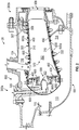
FIG. 2 , with continued reference toFIG. 1 , thecombustor section 26 of thegas turbine engine 20 is shown. Thecombustor 300 ofFIG. 2 is an impingement film float wall combustor. It is understood that while an impingement film float wall combustor is utilized for exemplary illustration, the embodiments disclosed herein may be applicable to other types of combustors for gas turbine engines including but not limited to double pass liner combustors, float wall combustors, and combustors with single wall liners. - As illustrated, a
combustor 300 defines acombustion chamber 302. Thecombustion chamber 302 includes acombustion area 370 within thecombustion chamber 302. Thecombustor 300 includes aninlet 306 and anoutlet 308 through which air may pass. The air may be supplied to thecombustor 300 by a pre-diffuser 110. Air may also enter thecombustion chamber 302 through other holes in thecombustor 300 including but not limited to quenchholes 310, as seen inFIG. 2 . - Compressor air is supplied from the
compressor section 24 into a pre-diffuser 110, which then directs the airflow toward thecombustor 300. Thecombustor 300 and the pre-diffuser 110 are separated by adump region 113 from which the flow separates into aninner shroud 114 and anouter shroud 116. As air enters thedump region 113, a portion of the air may flow into thecombustor inlet 306, a portion may flow into theinner shroud 114, and a portion may flow into theouter shroud 116. - The air from the
inner shroud 114 and theouter shroud 116 may then enter thecombustion chamber 302 by means of one or moreimpingement apertures 307 in thecombustor shell 600 and one ormore effusion apertures 309 in theheat shield panel 400, as shown inFIGS. 2 and3 . The impingement apertures 307 andeffusion apertures 309 may include nozzles, holes, etc. The air may then exit thecombustion chamber 302 through thecombustor outlet 308. At the same time, fuel may be injected into thecombustion chamber 302 through the primary and/or secondary orifices of afuel injector 320 and apilot nozzle 322, which may be atomized and mixed with air, and then ignited and burned within thecombustion chamber 302. Thediffuser case 124 defines theinner shroud 114 and theouter shroud 116. Thecombustor 300 is housed within thediffuser case 124 between theinner shroud 114 and theouter shroud 116. - The
combustor 300, as shown inFIG. 2 , includes multipleheat shield panels 400 that are attached to one or more combustor shells 600 (SeeFIG. 3 ). Theheat shield panels 400 may be arranged parallel to thecombustor shell 600. Thecombustor shell 600 includes a radiallyinward combustor shell 600a and a radiallyoutward combustor shell 600b defined thecombustion chamber 302 therebetween. Thecombustor shell 600 also includes aforward combustor shell 600c extending between the radiallyinward combustor shell 600a and the radiallyoutward combustor shell 600b. Theforward combustor shell 600c further bounds thecombustion chamber 302 on aforward end 300a of thecombustor 300. The radiallyinward combustor shell 600a and the radiallyoutward combustor shell 600b extend circumferentially around the longitudinal engine axis A. The radiallyinward combustor shell 600a is located radially inward from the radiallyoutward combustor shell 600b. - The
heat shield panels 400 can be removably mounted to thecombustor shell 600 by one ormore attachment mechanisms 332. In some embodiments, theattachment mechanism 332 may be integrally formed with a respectiveheat shield panel 400, although other configurations are possible. In some embodiments, theattachment mechanism 332 may be a threaded mounting stud or other structure that may extend from the respectiveheat shield panel 400 through the interior surface to a receiving portion or aperture of thecombustor shell 600 such that theheat shield panel 400 may be attached to thecombustor shell 600 and held in place. Theheat shield panels 400 partially enclose acombustion area 370 within thecombustion chamber 302 of thecombustor 300. - Referring now to
FIG. 3 , with continued reference toFIGs. 1 and2 , aheat shield panel 400 andcombustor shell 600 of the combustor 300 (seeFIG. 2 ) that may be used within the gas turbine engine 20 (seeFIG. 1 ).Combustors 300 ofgas turbine engines 20, as well as other components, experience elevated heat levels during operation. Impingement and convective cooling ofheat shield panels 400 of thecombustor 300 may be used to help cool thecombustor 300. Convective cooling may be achieved by air that is channeled between theheat shield panels 400 and acombustor shell 600 of thecombustor 300. Impingement cooling may be a process of directing relatively cool air from a location exterior to thecombustor 300 toward a back or underside of theheat shield panels 400. - Thus,
heat shield panels 400 are utilized to face the hot products of combustion within acombustion chamber 302 and protect thecombustor shell 600 of thecombustor 300. Theheat shield panels 400 may be supplied with cooling air through theimpingement apertures 307 and other dilution passages which deliver a high volume of cooling air into a hot flow path. The cooling air may be air from the compressor of thegas turbine engine 20. The cooling air may impinge upon a back side (i.e., second surface 420) of theheat shield panel 400 that faces thecombustor shell 600 inside thecombustor 300. The cooling air may contain particulates, which may build up on theheat shield panels 400 overtime, thus reducing the cooling ability of the cooling air. Embodiments disclosed herein seek to address particulate adherence to theheat shield panels 400 in order to maintain the cooling ability of the cooling air. - The
heat shield panel 400 and thecombustor shell 600 are in a facing spaced relationship. Theheat shield panel 400 includes afirst surface 410 oriented towards thecombustion area 370 of thecombustion chamber 302 and asecond surface 420 opposite thefirst surface 410 oriented towards thecombustor shell 600. Thecombustor shell 600 has aninner surface 610 and anouter surface 620 opposite theinner surface 610. Theinner surface 610 is oriented toward theheat shield panel 400. Theouter surface 620 is oriented outward from thecombustor 300 proximate theinner shroud 114 and theouter shroud 116. - The
combustor shell 600 includes a plurality ofimpingement apertures 307 configured to allowairflow 590 from theinner shroud 114 and theouter shroud 116 to enter animpingement cavity 390 located between thecombustor shell 600 and theheat shield panel 400. Each of theimpingement apertures 307 extend from theouter surface 620 to theinner surface 610 through thecombustor shell 600. Each of theimpingement apertures 307 fluidly connects theimpingement cavity 390 to at least one of theinner shroud 114 and theouter shroud 116. Conventionally, theseimpingement apertures 307 have been circular in shape (see.FIG. 5 ). - The
heat shield panel 400 may include one ormore effusion apertures 309 configured to allowairflow 590 from theimpingement cavity 390 to thecombustion area 370 of thecombustion chamber 302. Each of theeffusion apertures 309 extend from thesecond surface 420 to thefirst surface 410 through theheat shield panel 400.Airflow 590 flowing into theimpingement cavity 390 impinges on thesecond surface 420 of theheat shield panel 400 and absorbs heat from theheat shield panel 400. - As seen in
FIG. 3 , particulate 592 may accompany theairflow 590 flowing into theimpingement cavity 390.Particulate 592 may include but is not limited to dirt, smoke, soot, volcanic ash, or similar airborne particulate known to one of skill in the art. As theairflow 590 and particulate 592 impinge upon thesecond surface 420 of theheat shield panel 400, the particulate 592 may begin to collect on thesecond surface 420, as seen inFIG. 3 .Particulate 592 collecting upon thesecond surface 420 of theheat shield panel 400 reduces the cooling efficiency ofairflow 590 impinging upon thesecond surface 420 and thus may increase local temperatures of theheat shield panel 400 and thecombustor shell 600.Particulate 592 collection upon thesecond surface 420 of theheat shield panel 400 may potentially create ablockage 593 to theeffusion apertures 309 in theheat shield panels 400, thus reducingairflow 590 into thecombustion area 370 of thecombustion chamber 302. Theblockage 593 may be a partial blockage or a full blockage. - Embodiments disclosed herein seek to reduce the amount of particulate adhering the
second surface 420 of theheat shield panel 400 by adjusting the shape of theimpingement apertures 307 to disturb vorticities that are conventionally generated byimpingement apertures 307 that are circular in shape, which helps better disperse particulate 592. - Referring now to
FIGS. 4-10 , with continued reference toFIGS. 1-3 , aheat shield panel 400 and acombustor shell 600 of thecombustor 300, are illustrated in accordance with an embodiment of the present disclosure. Thecombustor shell 600 ofFIG. 4 comprises one or moreimpingement apertures 307 that have nonaxisymmetric shapes (i.e., not axisymmetric in shape). Axisymmetric may be defined as being symmetric about an axis and thus nonaxisymmetric may be defined as not symmetric about an axis or in other words not axisymmetric. -
FIG. 5 illustrates animpingement aperture 307 that is axisymmetric in shape. Theimpingement aperture 307 ofFIG. 5 is circular in shape and is axisymmetric about a longitudinal axis B of theimpingement apertures 307.FIG. 5 illustrates that theimpingement aperture 307 is axisymmetric in shape because asingle plane 307a may be rotated 360 degrees around the longitudinal axis B to form the axisymmetric shape. This differs from animpingement aperture 307 that is nonaxisymmetric in shape (as inFIGS 4 and6-8 ) because the nonaxisymmetric shape cannot be formed by asingle plane 307a rotated 360 degrees around the longitudinal axis B. - The
impingement aperture 307 ofFIG. 4 is crescent-shaped and is nonaxisymmetric about a longitudinal axis B of theimpingement aperture 307. Theimpingement aperture 307 extends from theouter surface 620 to theinner surface 610 through thecombustor shell 600. In an embodiment, the nonaxisymmetric shape of theimpingement aperture 307 extends from theouter surface 620 to theinner surface 610 through thecombustor shell 600. - An
impingement aperture 307 that is nonaxisymmetric in shape may have two ormore walls 307b that form theimpingement aperture 307 by extending from theouter surface 620 to theinner surface 610 through the combustor shell 600 (seeFIGS. 6-8 ). Animpingement aperture 307 that is axisymmetric in shape typically only has onewall 307b that forms theimpingement aperture 307 by extending from theouter surface 620 to theinner surface 610 through the combustor shell 600 (seeFIG. 5 ). Animpingement aperture 307 that is nonaxisymmetric in shape may also have only onewall 307b that forms theimpingement aperture 307 by extending from theouter surface 620 to theinner surface 610 through thecombustor shell 600. For example, animpingement aperture 307 that is nonaxisymmetric in shape and only has onewall 307b may be oval-shaped, as illustrated inFIG. 9 . In an embodiment, theimpingement aperture 307 is oval-shaped. - While the
impingement apertures 307 ofFIG. 4 are crescent-shaped, it is understood that theimpingement apertures 307 may have any other nonaxisymmetric shapes. Some other examples of nonaxisymmetric shapes are illustrated inFIGS. 6-10 . - An
impingement aperture 307 that is nonaxisymmetric in shape may be formed by combining various intersecting shapes (e.g.,FIG. 6 , and10 ). In an embodiment, a shape of theimpingement aperture 307 is composed of two or more intersecting shapes, as illustrated inFIGS. 6 and10 . The two or more intersecting shapes may be circles or any other shape. Additionally, a shape of theimpingement aperture 307 may also be composed of two or more intersecting shape shapes that are different, such as, for example, a circle and a square. The two-or more shapes may be in aligned in anarc 307c. For example, the crescent-shape may be formed by three intersecting circles in anarc 307c, as illustrated inFIG. 10 . Theimpingement aperture 307 ofFIG. 6 has a shape of two intersecting circles and is nonaxisymmetric about a longitudinal axis B of theimpingement aperture 307. It is understood that while the two intersecting circles are different sizes inFIG. 6 , the two intersecting circles may also be the same size. - Advantageously, manufacturing is eased when the nonaxisymetric shape is formed by intersecting circles. The nonaxisymetric shape may be formed by various manufacturing methods, including but not limited to laser drilling or a water jet.
- The
impingement aperture 307 ofFIG. 7 is comma-shaped and is nonaxisymmetric about a longitudinal axis B of theimpingement aperture 307. In an embodiment, theimpingement aperture 307 is comma-shaped. Theimpingement aperture 307 ofFIG. 8 is star-shaped and is nonaxisymmetric about a longitudinal axis B of theimpingement aperture 307. In an embodiment, theimpingement aperture 307 is star-shaped. It is understood that while the star-shape of theimpingement aperture 307 ofFIG. 8 is a four-point star, the star-shape may have any number of points. Theimpingement aperture 307 ofFIG. 9 is oval-shaped and is nonaxisymmetric about a longitudinal axis B of theimpingement aperture 307. In an embodiment, theimpingement aperture 307 is oval-shaped. - The
impingement aperture 307 ofFIG. 10 is arc-shaped and is nonaxisymmetric about a longitudinal axis B of theimpingement aperture 307. In an embodiment, theimpingement aperture 307 is arc-shaped. The arc shape ofFIG. 10 is formed by three-intersecting shapes aligned in anarc 307c. In an embodiment, the arc shape ofFIG. 10 is formed by three-intersecting circles aligned in anarc 307c. -
Impingement apertures 307 that are axisymmetric in shape direct air in an impingement jet in the form of circular vortex rings towards thesecond surface 420 of theheat shield panel 400 for impingement cooling. These vortices concentrate particulate near thesecond surface 420 of theheat shield panel 400 and in particular near a stagnation region of the impingement jet where particulate can agglomerate due to small local velocities along surface. This may inadvertently lead to build up ofparticulate 592 on thesecond surface 420 of the heat shield panel 400(seeFIG. 3 ). Advantageously, by utilizingimpingement apertures 307 that are nonaxisymmetric in shape, the vortices that are formed break up rapidly and thecooling airflow 590 hits thesecond surface 420 of theheat shield panel 400 in a non-uniform or variable manor, thus particulate 592 is dispersed better on thesecond surface 420 of theheat shield panel 400 by dispersing in non-uniform or variable manor. - Technical effects of embodiments of the present disclosure include shaping impingement apertures of combustor lines in an nonaxisymmetric shape to eliminate consistent vortices from the impingement apertures and promote dispersion of particulate.
- The term "about" is intended to include the degree of error associated with measurement of the particular quantity based upon the equipment available at the time of filing the application.
- The terminology used herein is for the purpose of describing particular embodiments only and is not intended to be limiting of the present disclosure. As used herein, the singular forms "a", "an" and "the" are intended to include the plural forms as well, unless the context clearly indicates otherwise. It will be further understood that the terms "comprises" and/or "comprising," when used in this specification, specify the presence of stated features, integers, steps, operations, elements, and/or components, but do not preclude the presence or addition of one or more other features, integers, steps, operations, element components, and/or groups thereof.
- While the present invention has been described with reference to an exemplary embodiment or embodiments, it will be understood by those skilled in the art that various changes may be made and equivalents may be substituted for elements thereof without departing from the scope of the present invention as defined by the claims. Therefore, it is intended that the present invention not be limited to the particular embodiment disclosed as the best mode contemplated for carrying out this present invention, but that the present invention will include all embodiments falling within the scope of the claims.
Claims (12)
- A combustor (300) for use in a gas turbine engine (20), the combustor comprising:a heat shield panel (400) having a first surface (410) and a second surface (420) opposite the first surface of the heat shield panel; anda combustor shell (600) having an inner surface (610) and an outer surface (620) opposite the inner surface, the inner surface of the combustor shell and the second surface of the heat shield panel being in a facing spaced relationship defining an impingement cavity (390) therebetween,wherein the combustor shell further comprises an impingement aperture (307) that has a nonaxisymmetric shape, the impingement aperture extending from the outer surface to the inner surface through the combustor shell.
- The combustor of claim 1, wherein the nonaxisymmetric shape of the impingement aperture (307) extends from the outer surface (620) to the inner surface (610) through the combustor shell (600).
- The combustor of claim 1 or claim 2, wherein the impingement aperture (307) has only one wall (307b) that forms the impingement aperture by extending from the outer surface (620) to the inner surface (610) through the combustor shell (600).
- The combustor of claim 1 or claim 2, wherein the impingement aperture (307) has two or more walls (307b) that form the impingement aperture by extending from the outer surface (620) to the inner surface (610) through the combustor shell (600).
- The combustor of claim 1, claim 2 or claim 4, wherein the impingement aperture (307) is crescent-shaped.
- The combustor of claim 1, claim 2 or claim 4, wherein the impingement aperture (307) is star-shaped.
- The combustor of claim 1, claim 2 or claim 4, wherein the impingement aperture (307) is comma-shaped.
- The combustor of claim 1, claim 2 or claim 3, wherein the impingement aperture (307) is oval-shaped.
- The combustor of any preceding claim, wherein the nonaxisymmetric shape of the impingement aperture (307) is composed of two or more intersecting shapes.
- The combustor of claim 9, wherein the two or more intersecting shapes are circles.
- The combustor of claim 9 or claim 10, wherein the two or more intersecting shapes are aligned in an arc (307c).
- A gas turbine engine (20), comprising:a combustor section (26); andthe combustor (300) of any preceding claim housed within the combustor section.
Applications Claiming Priority (1)
| Application Number | Priority Date | Filing Date | Title |
|---|---|---|---|
| US16/778,373 US11959641B2 (en) | 2020-01-31 | 2020-01-31 | Combustor shell with shaped impingement holes |
Publications (2)
| Publication Number | Publication Date |
|---|---|
| EP3859212A1 true EP3859212A1 (en) | 2021-08-04 |
| EP3859212B1 EP3859212B1 (en) | 2025-06-25 |
Family
ID=74418329
Family Applications (1)
| Application Number | Title | Priority Date | Filing Date |
|---|---|---|---|
| EP21154373.1A Active EP3859212B1 (en) | 2020-01-31 | 2021-01-29 | Combustor shell with shaped impingement holes |
Country Status (2)
| Country | Link |
|---|---|
| US (1) | US11959641B2 (en) |
| EP (1) | EP3859212B1 (en) |
Families Citing this family (2)
| Publication number | Priority date | Publication date | Assignee | Title |
|---|---|---|---|---|
| CN116989354A (en) | 2022-04-26 | 2023-11-03 | 通用电气公司 | Burner lining with shaped dilution openings |
| US12320304B2 (en) | 2023-08-18 | 2025-06-03 | General Electric Company | Gas turbine engine including a compressor bleed air system |
Citations (5)
| Publication number | Priority date | Publication date | Assignee | Title |
|---|---|---|---|---|
| US20130209236A1 (en) * | 2012-02-15 | 2013-08-15 | United Technologies Corporation | Gas turbine engine component with compound cusp cooling configuration |
| US20140238028A1 (en) * | 2011-11-08 | 2014-08-28 | Ihi Corporation | Impingement cooling mechanism, turbine blade, and combustor |
| US20170343217A1 (en) * | 2016-05-26 | 2017-11-30 | Siemens Energy, Inc. | Ducting arrangement with injector assemblies arranged in an expanding cross-sectional area of a downstream combustion stage in a gas turbine engine |
| US20180320898A1 (en) * | 2017-05-08 | 2018-11-08 | Doosan Heavy Industries & Construction Co., Ltd | Combustor, gas turbine including the same and method of distributing compressed air in combustor |
| US20190277501A1 (en) * | 2018-03-07 | 2019-09-12 | United Technologies Corporation | Slot arrangements for an impingement floatwall film cooling of a turbine engine |
Family Cites Families (9)
| Publication number | Priority date | Publication date | Assignee | Title |
|---|---|---|---|---|
| EP1275818B1 (en) | 2001-07-13 | 2006-08-16 | ALSTOM Technology Ltd | Gas turbine component with cooling holes |
| US7146815B2 (en) * | 2003-07-31 | 2006-12-12 | United Technologies Corporation | Combustor |
| DE102006026969A1 (en) | 2006-06-09 | 2007-12-13 | Rolls-Royce Deutschland Ltd & Co Kg | Gas turbine combustor wall for a lean-burn gas turbine combustor |
| US8056342B2 (en) * | 2008-06-12 | 2011-11-15 | United Technologies Corporation | Hole pattern for gas turbine combustor |
| US9151173B2 (en) * | 2011-12-15 | 2015-10-06 | General Electric Company | Use of multi-faceted impingement openings for increasing heat transfer characteristics on gas turbine components |
| DE102012025375A1 (en) | 2012-12-27 | 2014-07-17 | Rolls-Royce Deutschland Ltd & Co Kg | Method for arranging impingement cooling holes and effusion holes in a combustion chamber wall of a gas turbine |
| WO2016025054A2 (en) * | 2014-05-29 | 2016-02-18 | General Electric Company | Engine components with cooling features |
| US20180128177A1 (en) | 2016-11-07 | 2018-05-10 | General Electric Company | Method for forming a hole in an engine component |
| US10590779B2 (en) * | 2017-12-05 | 2020-03-17 | United Technologies Corporation | Double wall turbine gas turbine engine blade cooling configuration |
-
2020
- 2020-01-31 US US16/778,373 patent/US11959641B2/en active Active
-
2021
- 2021-01-29 EP EP21154373.1A patent/EP3859212B1/en active Active
Patent Citations (5)
| Publication number | Priority date | Publication date | Assignee | Title |
|---|---|---|---|---|
| US20140238028A1 (en) * | 2011-11-08 | 2014-08-28 | Ihi Corporation | Impingement cooling mechanism, turbine blade, and combustor |
| US20130209236A1 (en) * | 2012-02-15 | 2013-08-15 | United Technologies Corporation | Gas turbine engine component with compound cusp cooling configuration |
| US20170343217A1 (en) * | 2016-05-26 | 2017-11-30 | Siemens Energy, Inc. | Ducting arrangement with injector assemblies arranged in an expanding cross-sectional area of a downstream combustion stage in a gas turbine engine |
| US20180320898A1 (en) * | 2017-05-08 | 2018-11-08 | Doosan Heavy Industries & Construction Co., Ltd | Combustor, gas turbine including the same and method of distributing compressed air in combustor |
| US20190277501A1 (en) * | 2018-03-07 | 2019-09-12 | United Technologies Corporation | Slot arrangements for an impingement floatwall film cooling of a turbine engine |
Also Published As
| Publication number | Publication date |
|---|---|
| US11959641B2 (en) | 2024-04-16 |
| US20210239320A1 (en) | 2021-08-05 |
| EP3859212B1 (en) | 2025-06-25 |
Similar Documents
| Publication | Publication Date | Title |
|---|---|---|
| EP3502440B1 (en) | Gas turbine engine component assembly | |
| EP3502562B1 (en) | Apparatus and method for mitigating particulate accumulation on a component of a gas turbine engine | |
| EP3734161B1 (en) | Gas turbine engine combustor comprising a liner panel with micro-circuit core cooling | |
| US20220381434A1 (en) | Apparatus and method for mitigating particulate accumulation on a component of a gas turbine | |
| US20240247613A1 (en) | Apparatus and method for mitigating airflow separation around engine combustor | |
| US11092339B2 (en) | Apparatus and method for mitigating particulate accumulation on a component of a gas turbine | |
| US11268696B2 (en) | Slot cooled combustor | |
| EP3492813B1 (en) | Apparatus for mitigating particulate accumulation on a shell of a combustor of a gas turbine engine | |
| US11371703B2 (en) | Apparatus and method for mitigating particulate accumulation on a component of a gas turbine | |
| EP3859212B1 (en) | Combustor shell with shaped impingement holes | |
| EP3502564B1 (en) | Combustor shell mitigating particulate accumulation on the bulkhead of a gas turbine engine | |
| EP3770501B1 (en) | Gasturbine engine with a combustor comprising a particulate deflector | |
| US11098653B2 (en) | Apparatus and method for mitigating particulate accumulation on a component of a gas turbine | |
| EP3511624B1 (en) | Combustor for a gas turbine engine mitigating particulate accumulation | |
| US20190368734A1 (en) | Design and manufacturing process for directed impingement punched plates | |
| EP3543477B1 (en) | Hooded entrance to effusion holes |
Legal Events
| Date | Code | Title | Description |
|---|---|---|---|
| PUAI | Public reference made under article 153(3) epc to a published international application that has entered the european phase |
Free format text: ORIGINAL CODE: 0009012 |
|
| STAA | Information on the status of an ep patent application or granted ep patent |
Free format text: STATUS: THE APPLICATION HAS BEEN PUBLISHED |
|
| AK | Designated contracting states |
Kind code of ref document: A1 Designated state(s): AL AT BE BG CH CY CZ DE DK EE ES FI FR GB GR HR HU IE IS IT LI LT LU LV MC MK MT NL NO PL PT RO RS SE SI SK SM TR |
|
| STAA | Information on the status of an ep patent application or granted ep patent |
Free format text: STATUS: REQUEST FOR EXAMINATION WAS MADE |
|
| 17P | Request for examination filed |
Effective date: 20220204 |
|
| RBV | Designated contracting states (corrected) |
Designated state(s): AL AT BE BG CH CY CZ DE DK EE ES FI FR GB GR HR HU IE IS IT LI LT LU LV MC MK MT NL NO PL PT RO RS SE SI SK SM TR |
|
| STAA | Information on the status of an ep patent application or granted ep patent |
Free format text: STATUS: EXAMINATION IS IN PROGRESS |
|
| 17Q | First examination report despatched |
Effective date: 20221219 |
|
| RAP3 | Party data changed (applicant data changed or rights of an application transferred) |
Owner name: RTX CORPORATION |
|
| GRAP | Despatch of communication of intention to grant a patent |
Free format text: ORIGINAL CODE: EPIDOSNIGR1 |
|
| STAA | Information on the status of an ep patent application or granted ep patent |
Free format text: STATUS: GRANT OF PATENT IS INTENDED |
|
| INTG | Intention to grant announced |
Effective date: 20250121 |
|
| GRAS | Grant fee paid |
Free format text: ORIGINAL CODE: EPIDOSNIGR3 |
|
| GRAA | (expected) grant |
Free format text: ORIGINAL CODE: 0009210 |
|
| STAA | Information on the status of an ep patent application or granted ep patent |
Free format text: STATUS: THE PATENT HAS BEEN GRANTED |
|
| AK | Designated contracting states |
Kind code of ref document: B1 Designated state(s): AL AT BE BG CH CY CZ DE DK EE ES FI FR GB GR HR HU IE IS IT LI LT LU LV MC MK MT NL NO PL PT RO RS SE SI SK SM TR |
|
| REG | Reference to a national code |
Ref country code: GB Ref legal event code: FG4D |
|
| REG | Reference to a national code |
Ref country code: CH Ref legal event code: EP |
|
| REG | Reference to a national code |
Ref country code: DE Ref legal event code: R096 Ref document number: 602021032663 Country of ref document: DE |
|
| REG | Reference to a national code |
Ref country code: CH Ref legal event code: EP |
|
| REG | Reference to a national code |
Ref country code: IE Ref legal event code: FG4D |
|
| PG25 | Lapsed in a contracting state [announced via postgrant information from national office to epo] |
Ref country code: FI Free format text: LAPSE BECAUSE OF FAILURE TO SUBMIT A TRANSLATION OF THE DESCRIPTION OR TO PAY THE FEE WITHIN THE PRESCRIBED TIME-LIMIT Effective date: 20250625 |
|
| REG | Reference to a national code |
Ref country code: LT Ref legal event code: MG9D |
|
| PG25 | Lapsed in a contracting state [announced via postgrant information from national office to epo] |
Ref country code: NO Free format text: LAPSE BECAUSE OF FAILURE TO SUBMIT A TRANSLATION OF THE DESCRIPTION OR TO PAY THE FEE WITHIN THE PRESCRIBED TIME-LIMIT Effective date: 20250925 Ref country code: GR Free format text: LAPSE BECAUSE OF FAILURE TO SUBMIT A TRANSLATION OF THE DESCRIPTION OR TO PAY THE FEE WITHIN THE PRESCRIBED TIME-LIMIT Effective date: 20250926 |
|
| PG25 | Lapsed in a contracting state [announced via postgrant information from national office to epo] |
Ref country code: BG Free format text: LAPSE BECAUSE OF FAILURE TO SUBMIT A TRANSLATION OF THE DESCRIPTION OR TO PAY THE FEE WITHIN THE PRESCRIBED TIME-LIMIT Effective date: 20250625 |
|
| PG25 | Lapsed in a contracting state [announced via postgrant information from national office to epo] |
Ref country code: HR Free format text: LAPSE BECAUSE OF FAILURE TO SUBMIT A TRANSLATION OF THE DESCRIPTION OR TO PAY THE FEE WITHIN THE PRESCRIBED TIME-LIMIT Effective date: 20250625 |
|
| PG25 | Lapsed in a contracting state [announced via postgrant information from national office to epo] |
Ref country code: RS Free format text: LAPSE BECAUSE OF FAILURE TO SUBMIT A TRANSLATION OF THE DESCRIPTION OR TO PAY THE FEE WITHIN THE PRESCRIBED TIME-LIMIT Effective date: 20250925 |
|
| PG25 | Lapsed in a contracting state [announced via postgrant information from national office to epo] |
Ref country code: LV Free format text: LAPSE BECAUSE OF FAILURE TO SUBMIT A TRANSLATION OF THE DESCRIPTION OR TO PAY THE FEE WITHIN THE PRESCRIBED TIME-LIMIT Effective date: 20250625 |
|
| REG | Reference to a national code |
Ref country code: NL Ref legal event code: MP Effective date: 20250625 |
|
| PG25 | Lapsed in a contracting state [announced via postgrant information from national office to epo] |
Ref country code: NL Free format text: LAPSE BECAUSE OF FAILURE TO SUBMIT A TRANSLATION OF THE DESCRIPTION OR TO PAY THE FEE WITHIN THE PRESCRIBED TIME-LIMIT Effective date: 20250625 |
|
| PG25 | Lapsed in a contracting state [announced via postgrant information from national office to epo] |
Ref country code: PT Free format text: LAPSE BECAUSE OF FAILURE TO SUBMIT A TRANSLATION OF THE DESCRIPTION OR TO PAY THE FEE WITHIN THE PRESCRIBED TIME-LIMIT Effective date: 20251027 |
|
| REG | Reference to a national code |
Ref country code: AT Ref legal event code: MK05 Ref document number: 1806770 Country of ref document: AT Kind code of ref document: T Effective date: 20250625 |
|
| PG25 | Lapsed in a contracting state [announced via postgrant information from national office to epo] |
Ref country code: IS Free format text: LAPSE BECAUSE OF FAILURE TO SUBMIT A TRANSLATION OF THE DESCRIPTION OR TO PAY THE FEE WITHIN THE PRESCRIBED TIME-LIMIT Effective date: 20251025 |
|
| PGFP | Annual fee paid to national office [announced via postgrant information from national office to epo] |
Ref country code: GB Payment date: 20251220 Year of fee payment: 6 |
|
| PG25 | Lapsed in a contracting state [announced via postgrant information from national office to epo] |
Ref country code: AT Free format text: LAPSE BECAUSE OF FAILURE TO SUBMIT A TRANSLATION OF THE DESCRIPTION OR TO PAY THE FEE WITHIN THE PRESCRIBED TIME-LIMIT Effective date: 20250625 Ref country code: SM Free format text: LAPSE BECAUSE OF FAILURE TO SUBMIT A TRANSLATION OF THE DESCRIPTION OR TO PAY THE FEE WITHIN THE PRESCRIBED TIME-LIMIT Effective date: 20250625 |
|
| PGFP | Annual fee paid to national office [announced via postgrant information from national office to epo] |
Ref country code: FR Payment date: 20251217 Year of fee payment: 6 |
|
| PG25 | Lapsed in a contracting state [announced via postgrant information from national office to epo] |
Ref country code: CZ Free format text: LAPSE BECAUSE OF FAILURE TO SUBMIT A TRANSLATION OF THE DESCRIPTION OR TO PAY THE FEE WITHIN THE PRESCRIBED TIME-LIMIT Effective date: 20250625 |
|
| PG25 | Lapsed in a contracting state [announced via postgrant information from national office to epo] |
Ref country code: PL Free format text: LAPSE BECAUSE OF FAILURE TO SUBMIT A TRANSLATION OF THE DESCRIPTION OR TO PAY THE FEE WITHIN THE PRESCRIBED TIME-LIMIT Effective date: 20250625 |
|
| PG25 | Lapsed in a contracting state [announced via postgrant information from national office to epo] |
Ref country code: EE Free format text: LAPSE BECAUSE OF FAILURE TO SUBMIT A TRANSLATION OF THE DESCRIPTION OR TO PAY THE FEE WITHIN THE PRESCRIBED TIME-LIMIT Effective date: 20250625 |
|
| PG25 | Lapsed in a contracting state [announced via postgrant information from national office to epo] |
Ref country code: SK Free format text: LAPSE BECAUSE OF FAILURE TO SUBMIT A TRANSLATION OF THE DESCRIPTION OR TO PAY THE FEE WITHIN THE PRESCRIBED TIME-LIMIT Effective date: 20250625 |
|
| PG25 | Lapsed in a contracting state [announced via postgrant information from national office to epo] |
Ref country code: ES Free format text: LAPSE BECAUSE OF FAILURE TO SUBMIT A TRANSLATION OF THE DESCRIPTION OR TO PAY THE FEE WITHIN THE PRESCRIBED TIME-LIMIT Effective date: 20250625 |
|
| PG25 | Lapsed in a contracting state [announced via postgrant information from national office to epo] |
Ref country code: DK Free format text: LAPSE BECAUSE OF FAILURE TO SUBMIT A TRANSLATION OF THE DESCRIPTION OR TO PAY THE FEE WITHIN THE PRESCRIBED TIME-LIMIT Effective date: 20250625 |
|
| PGFP | Annual fee paid to national office [announced via postgrant information from national office to epo] |
Ref country code: DE Payment date: 20251217 Year of fee payment: 6 |
|
| PG25 | Lapsed in a contracting state [announced via postgrant information from national office to epo] |
Ref country code: IT Free format text: LAPSE BECAUSE OF FAILURE TO SUBMIT A TRANSLATION OF THE DESCRIPTION OR TO PAY THE FEE WITHIN THE PRESCRIBED TIME-LIMIT Effective date: 20250625 |
|
| PLBE | No opposition filed within time limit |
Free format text: ORIGINAL CODE: 0009261 |
|
| STAA | Information on the status of an ep patent application or granted ep patent |
Free format text: STATUS: NO OPPOSITION FILED WITHIN TIME LIMIT |
|
| REG | Reference to a national code |
Ref country code: CH Ref legal event code: L10 Free format text: ST27 STATUS EVENT CODE: U-0-0-L10-L00 (AS PROVIDED BY THE NATIONAL OFFICE) Effective date: 20260507 |