EP3859162A1 - Magnetic bearing cooling management - Google Patents
Magnetic bearing cooling management Download PDFInfo
- Publication number
- EP3859162A1 EP3859162A1 EP21154444.0A EP21154444A EP3859162A1 EP 3859162 A1 EP3859162 A1 EP 3859162A1 EP 21154444 A EP21154444 A EP 21154444A EP 3859162 A1 EP3859162 A1 EP 3859162A1
- Authority
- EP
- European Patent Office
- Prior art keywords
- compressor
- shield
- working fluid
- disposed
- jet
- Prior art date
- Legal status (The legal status is an assumption and is not a legal conclusion. Google has not performed a legal analysis and makes no representation as to the accuracy of the status listed.)
- Granted
Links
Images


Classifications
-
- H—ELECTRICITY
- H02—GENERATION; CONVERSION OR DISTRIBUTION OF ELECTRIC POWER
- H02K—DYNAMO-ELECTRIC MACHINES
- H02K5/00—Casings; Enclosures; Supports
- H02K5/04—Casings or enclosures characterised by the shape, form or construction thereof
- H02K5/08—Insulating casings
-
- F—MECHANICAL ENGINEERING; LIGHTING; HEATING; WEAPONS; BLASTING
- F04—POSITIVE - DISPLACEMENT MACHINES FOR LIQUIDS; PUMPS FOR LIQUIDS OR ELASTIC FLUIDS
- F04D—NON-POSITIVE-DISPLACEMENT PUMPS
- F04D29/00—Details, component parts, or accessories
- F04D29/05—Shafts or bearings, or assemblies thereof, specially adapted for elastic fluid pumps
- F04D29/056—Bearings
- F04D29/058—Bearings magnetic; electromagnetic
-
- F—MECHANICAL ENGINEERING; LIGHTING; HEATING; WEAPONS; BLASTING
- F04—POSITIVE - DISPLACEMENT MACHINES FOR LIQUIDS; PUMPS FOR LIQUIDS OR ELASTIC FLUIDS
- F04D—NON-POSITIVE-DISPLACEMENT PUMPS
- F04D29/00—Details, component parts, or accessories
- F04D29/58—Cooling; Heating; Diminishing heat transfer
- F04D29/5806—Cooling the drive system
-
- F—MECHANICAL ENGINEERING; LIGHTING; HEATING; WEAPONS; BLASTING
- F04—POSITIVE - DISPLACEMENT MACHINES FOR LIQUIDS; PUMPS FOR LIQUIDS OR ELASTIC FLUIDS
- F04C—ROTARY-PISTON, OR OSCILLATING-PISTON, POSITIVE-DISPLACEMENT MACHINES FOR LIQUIDS; ROTARY-PISTON, OR OSCILLATING-PISTON, POSITIVE-DISPLACEMENT PUMPS
- F04C18/00—Rotary-piston pumps specially adapted for elastic fluids
- F04C18/02—Rotary-piston pumps specially adapted for elastic fluids of arcuate-engagement type, i.e. with circular translatory movement of co-operating members, each member having the same number of teeth or tooth-equivalents
-
- F—MECHANICAL ENGINEERING; LIGHTING; HEATING; WEAPONS; BLASTING
- F04—POSITIVE - DISPLACEMENT MACHINES FOR LIQUIDS; PUMPS FOR LIQUIDS OR ELASTIC FLUIDS
- F04C—ROTARY-PISTON, OR OSCILLATING-PISTON, POSITIVE-DISPLACEMENT MACHINES FOR LIQUIDS; ROTARY-PISTON, OR OSCILLATING-PISTON, POSITIVE-DISPLACEMENT PUMPS
- F04C18/00—Rotary-piston pumps specially adapted for elastic fluids
- F04C18/02—Rotary-piston pumps specially adapted for elastic fluids of arcuate-engagement type, i.e. with circular translatory movement of co-operating members, each member having the same number of teeth or tooth-equivalents
- F04C18/0207—Rotary-piston pumps specially adapted for elastic fluids of arcuate-engagement type, i.e. with circular translatory movement of co-operating members, each member having the same number of teeth or tooth-equivalents both members having co-operating elements in spiral form
-
- F—MECHANICAL ENGINEERING; LIGHTING; HEATING; WEAPONS; BLASTING
- F04—POSITIVE - DISPLACEMENT MACHINES FOR LIQUIDS; PUMPS FOR LIQUIDS OR ELASTIC FLUIDS
- F04C—ROTARY-PISTON, OR OSCILLATING-PISTON, POSITIVE-DISPLACEMENT MACHINES FOR LIQUIDS; ROTARY-PISTON, OR OSCILLATING-PISTON, POSITIVE-DISPLACEMENT PUMPS
- F04C2/00—Rotary-piston machines or pumps
- F04C2/02—Rotary-piston machines or pumps of arcuate-engagement type, i.e. with circular translatory movement of co-operating members, each member having the same number of teeth or tooth-equivalents
-
- F—MECHANICAL ENGINEERING; LIGHTING; HEATING; WEAPONS; BLASTING
- F04—POSITIVE - DISPLACEMENT MACHINES FOR LIQUIDS; PUMPS FOR LIQUIDS OR ELASTIC FLUIDS
- F04C—ROTARY-PISTON, OR OSCILLATING-PISTON, POSITIVE-DISPLACEMENT MACHINES FOR LIQUIDS; ROTARY-PISTON, OR OSCILLATING-PISTON, POSITIVE-DISPLACEMENT PUMPS
- F04C29/00—Component parts, details or accessories of pumps or pumping installations, not provided for in groups F04C18/00 - F04C28/00
- F04C29/04—Heating; Cooling; Heat insulation
-
- F—MECHANICAL ENGINEERING; LIGHTING; HEATING; WEAPONS; BLASTING
- F04—POSITIVE - DISPLACEMENT MACHINES FOR LIQUIDS; PUMPS FOR LIQUIDS OR ELASTIC FLUIDS
- F04C—ROTARY-PISTON, OR OSCILLATING-PISTON, POSITIVE-DISPLACEMENT MACHINES FOR LIQUIDS; ROTARY-PISTON, OR OSCILLATING-PISTON, POSITIVE-DISPLACEMENT PUMPS
- F04C29/00—Component parts, details or accessories of pumps or pumping installations, not provided for in groups F04C18/00 - F04C28/00
- F04C29/04—Heating; Cooling; Heat insulation
- F04C29/045—Heating; Cooling; Heat insulation of the electric motor in hermetic pumps
-
- F—MECHANICAL ENGINEERING; LIGHTING; HEATING; WEAPONS; BLASTING
- F04—POSITIVE - DISPLACEMENT MACHINES FOR LIQUIDS; PUMPS FOR LIQUIDS OR ELASTIC FLUIDS
- F04D—NON-POSITIVE-DISPLACEMENT PUMPS
- F04D25/00—Pumping installations or systems
- F04D25/02—Units comprising pumps and their driving means
- F04D25/06—Units comprising pumps and their driving means the pump being electrically driven
-
- F—MECHANICAL ENGINEERING; LIGHTING; HEATING; WEAPONS; BLASTING
- F04—POSITIVE - DISPLACEMENT MACHINES FOR LIQUIDS; PUMPS FOR LIQUIDS OR ELASTIC FLUIDS
- F04D—NON-POSITIVE-DISPLACEMENT PUMPS
- F04D25/00—Pumping installations or systems
- F04D25/02—Units comprising pumps and their driving means
- F04D25/06—Units comprising pumps and their driving means the pump being electrically driven
- F04D25/0606—Units comprising pumps and their driving means the pump being electrically driven the electric motor being specially adapted for integration in the pump
-
- F—MECHANICAL ENGINEERING; LIGHTING; HEATING; WEAPONS; BLASTING
- F04—POSITIVE - DISPLACEMENT MACHINES FOR LIQUIDS; PUMPS FOR LIQUIDS OR ELASTIC FLUIDS
- F04D—NON-POSITIVE-DISPLACEMENT PUMPS
- F04D29/00—Details, component parts, or accessories
- F04D29/05—Shafts or bearings, or assemblies thereof, specially adapted for elastic fluid pumps
- F04D29/051—Axial thrust balancing
-
- F—MECHANICAL ENGINEERING; LIGHTING; HEATING; WEAPONS; BLASTING
- F04—POSITIVE - DISPLACEMENT MACHINES FOR LIQUIDS; PUMPS FOR LIQUIDS OR ELASTIC FLUIDS
- F04D—NON-POSITIVE-DISPLACEMENT PUMPS
- F04D29/00—Details, component parts, or accessories
- F04D29/58—Cooling; Heating; Diminishing heat transfer
- F04D29/582—Cooling; Heating; Diminishing heat transfer specially adapted for elastic fluid pumps
- F04D29/584—Cooling; Heating; Diminishing heat transfer specially adapted for elastic fluid pumps cooling or heating the machine
-
- F—MECHANICAL ENGINEERING; LIGHTING; HEATING; WEAPONS; BLASTING
- F04—POSITIVE - DISPLACEMENT MACHINES FOR LIQUIDS; PUMPS FOR LIQUIDS OR ELASTIC FLUIDS
- F04D—NON-POSITIVE-DISPLACEMENT PUMPS
- F04D29/00—Details, component parts, or accessories
- F04D29/58—Cooling; Heating; Diminishing heat transfer
- F04D29/582—Cooling; Heating; Diminishing heat transfer specially adapted for elastic fluid pumps
- F04D29/5853—Cooling; Heating; Diminishing heat transfer specially adapted for elastic fluid pumps heat insulation or conduction
-
- H—ELECTRICITY
- H02—GENERATION; CONVERSION OR DISTRIBUTION OF ELECTRIC POWER
- H02K—DYNAMO-ELECTRIC MACHINES
- H02K5/00—Casings; Enclosures; Supports
- H02K5/04—Casings or enclosures characterised by the shape, form or construction thereof
- H02K5/16—Means for supporting bearings, e.g. insulating supports or means for fitting bearings in the bearing-shields
- H02K5/173—Means for supporting bearings, e.g. insulating supports or means for fitting bearings in the bearing-shields using bearings with rolling contact, e.g. ball bearings
- H02K5/1735—Means for supporting bearings, e.g. insulating supports or means for fitting bearings in the bearing-shields using bearings with rolling contact, e.g. ball bearings radially supporting the rotary shaft at only one end of the rotor
-
- H—ELECTRICITY
- H02—GENERATION; CONVERSION OR DISTRIBUTION OF ELECTRIC POWER
- H02K—DYNAMO-ELECTRIC MACHINES
- H02K9/00—Arrangements for cooling or ventilating
- H02K9/19—Arrangements for cooling or ventilating for machines with closed casing and closed-circuit cooling using a liquid cooling medium, e.g. oil
-
- F—MECHANICAL ENGINEERING; LIGHTING; HEATING; WEAPONS; BLASTING
- F04—POSITIVE - DISPLACEMENT MACHINES FOR LIQUIDS; PUMPS FOR LIQUIDS OR ELASTIC FLUIDS
- F04C—ROTARY-PISTON, OR OSCILLATING-PISTON, POSITIVE-DISPLACEMENT MACHINES FOR LIQUIDS; ROTARY-PISTON, OR OSCILLATING-PISTON, POSITIVE-DISPLACEMENT PUMPS
- F04C2210/00—Fluid
- F04C2210/26—Refrigerants with particular properties, e.g. HFC-134a
-
- F—MECHANICAL ENGINEERING; LIGHTING; HEATING; WEAPONS; BLASTING
- F04—POSITIVE - DISPLACEMENT MACHINES FOR LIQUIDS; PUMPS FOR LIQUIDS OR ELASTIC FLUIDS
- F04C—ROTARY-PISTON, OR OSCILLATING-PISTON, POSITIVE-DISPLACEMENT MACHINES FOR LIQUIDS; ROTARY-PISTON, OR OSCILLATING-PISTON, POSITIVE-DISPLACEMENT PUMPS
- F04C2240/00—Components
- F04C2240/50—Bearings
- F04C2240/56—Bearing bushings or details thereof
Definitions
- Hermetically cooled motors for example, the magnetically driven motors of centrifugal compressors, may use refrigerant to provide cooling.
- This refrigerant may be introduced inside the compressor in either a liquid phase or a vapor phase. Since refrigerant in a liquid phase has the ability to absorb more heat relative to refrigerant in a vapor phase, in certain instances, it is advantageous to inject refrigerant in a liquid phase into the compressor.
- Refrigerant can be used by magnetically driven compressors to provide cooling for the electric motor (e.g. the rotors) and the magnetic bearings.
- the bearings of the compressor are typically used to support the rotating shaft of the compressor.
- the rotors are typically mounted to the rotating shaft.
- refrigerant may be injected into the compressor (e.g. in liquid phase). The injection of the refrigerant is commonly completed using a fixed orifice that injects the refrigerant at a high enough rate to provide adequate cooling when the compressor is running at maximum load.
- refrigerant used to cool the electric motor may migrate toward the magnetic bearings causing the magnetic bearings to overcool. This may be especially prevalent when the compressor is operating at low load, which can result in more refrigerant pooling due to less heat being generated by the motor.
- the magnetic bearings When overcooled, the magnetic bearings may shrink. This can pose an issue with the sensors mounted to the magnetic bearings. These sensors are typically used to measure relative distances between the bearings and the adjacent components (e.g. the rotating shaft). When overcooled the sensors may malfunction (e.g. tripping the bearing controls) as a result of the reading showing the relative distance measured greater than an acceptable range.
- a shield for controlling the cooling within a hermetically cooled motor includes an insulator surface, at least one fastener aperture, and at least one venting aperture.
- the insulator surface includes a first side and a second side.
- the insulator surface is configured to restrict the flow of a working fluid.
- the at least one fastener aperture is disposed in the insulator surface.
- the at least one venting aperture is disposed in the insulator surface.
- the at least one venting aperture is configured to control a pressure differential between the first side and the second side.
- the shield includes an annulus shape having an outer diameter and an inner diameter.
- the at least one fastener aperture may be disposed circumferentially adjacent to the outer diameter, and the at least one venting aperture may be disposed circumferentially adjacent to the inner diameter.
- the insulator surface is made of a material with low electrical and thermal conductivity.
- the material is Garolite.
- a compressor including an electric motor, a magnetic bearing, and a shield disposed adjacent to the electric motor.
- the electric motor is used for driving a rotating shaft.
- the magnetic bearing is disposed adjacent to the electric motor.
- the shield includes an insulator surface configured to restrict the flow of a working fluid, at least one fastener aperture disposed in the insulator surface, and at least one venting aperture disposed in the insulator surface.
- the at least one venting aperture is configured to control a pressure differential between the first side and the second side.
- the shield includes an annulus shape having an outer diameter and an inner diameter.
- the at least one fastener aperture may be disposed circumferentially adjacent to the outer diameter.
- the at least one venting aperture may be disposed circumferentially adjacent to the inner diameter.
- the shaft passes through the annulus.
- the compressor further includes a fastening assembly, the fastening assembly configured to secure the shield to the magnetic bearing through at least one of the fastener apertures.
- the fastening assembly includes at least one of a fastener, a washer, and a sleeve.
- the compressor further includes at least one first jet disposed upstream of the shield, and at least one second jet disposed downstream of the shield.
- the at least one first jet and the at least one second jet may be configured to distribute the working fluid.
- the distributed working fluid is configured to pass through the at least one venting aperture.
- the at least one first jet is configured to distribute the working fluid to the electric motor.
- the at least one second jet is configured to distribute the working fluid to the magnetic bearing.
- the working fluid is in a substantially liquid phase.
- the working fluid is R-134A refrigerant.
- the compressor is a centrifugal compressor.
- the compressor is an axial compressor.
- the compressor is a scroll compressor.
- a shield for controlling the cooling within a hermetically cooled motor, and a compressor incorporating the same are provided.
- the shield makes it possible to prevent, or at least mitigate, the overcooling of the magnetic bearings within a compressor.
- the shield acts as a protective boundary by restricting the flow of refrigerant from an electric motor of a compressor toward a magnetic bearing of a compressor. By restricting the flow of refrigerant with a shield, cooling of the magnetic bearings within a compressor can be managed without requiring an active control (e.g. actively adjusting the amount of refrigerant being dispersed by one or more jet).
- the shield 110 could be used in any hermetically cooled motor, for purposes of simplicity and brevity, the shield 110 is described in terms of being used in a compressor 100.
- a compressor 100 with an electric motor 130 and a magnetic bearing 120 An exemplary depiction of a shield 110 within a compressor 100 with an electric motor 130 and a magnetic bearing 120 is shown in FIGs. 1 and 2 .
- the electric motor 130 is used by the compressor 100 for driving a rotating shaft 140.
- the magnetic bearing 120 is used by the compressor 100 for magnetically levitating the rotating shaft 140.
- a shield 110 is configured between the electric motor 130 and the magnetic bearing 120.
- the shield 110 includes an insulator 111, at least one fastener aperture 112, and a venting aperture 113.
- the shield 110 is configured such that one side (e.g. the first side 180) is adjacent to the electric motor 130, and the other side (e.g. the second side 190) is adjacent to the magnetic bearing 120.
- the shield 110 is configured to restrict the flow of a working fluid (e.g. refrigerant) between the electric motor 130 and the magnetic bearing 120. By restricting the flow of the working fluid, the shield 110, in certain instance, helps to prevent, or at least mitigate, overcooling of the magnetic bearing 120 within the compressor 100.
- a working fluid e.g. refrigerant
- the compressor 100 may include at least one jet 150.
- the jet 150 may be any orifice capable of injecting an effective amount of working fluid into the compressor 100 to prevent overheating.
- the compressor 100 includes at least one jet 150 upstream of the shield 110 and at least one jet 150 downstream of the shield 110.
- the jet(s) 150 upstream of the shield 110 may be used to distribute the working fluid to cool the electric motor 130.
- the jet(s) 150 downstream of the shield 110 may be used to distribute the working fluid to cool the magnetic bearing 120.
- the shield 110 by being configured between the electric motor 130 and the magnetic bearing 120, restricts the flow of the working fluid between the electric motor 130 and magnetic bearing 120. By restricting the flow of working fluid through the shield 110, in certain instances, helps to prevent, or at least mitigate, overcooling of the magnetic bearing 120.
- the working fluid injected into the first side 180 and the second side 190 of the shield is in a substantially liquid phase.
- a substantially liquid phase can be interpreted to mean that more of the working fluid is in liquid phase than vapor phase.
- the shield 110 allows for the working fluid to flow from the second side 190 of the shield 110 to the first side of the shield 180 so that the working fluid can pass to the drain 131 in the electric motor 130.
- the working fluid is R-134A refrigerant.
- the compressor is either a centrifugal compressor, an axial compressor, or a scroll compressor.
- the shield 110 includes an insulator 111 for restricting the flow of a working fluid (e.g. refrigerant) between a first side 180 and a second side 190 (shown in FIGs. 1 and 2 ).
- the shield 110 also includes at least one fastener aperture 112 disposed in the insulator 111 to enable the insulator 111 to be secured to the magnetic bearing 120 and/or the bearing housing 121.
- at least one fastener for example, one or more shoulder bolts (shown in FIGs. 4 and 5 ), can be inserted through the at least one fastener aperture 112.
- the shield 110 additionally includes at least one venting aperture 113 for controlling a pressure differential between the first side 180 and the second side 190.
- the venting aperture 113 in certain instances, is provided through use of at least one hole through the insulator 111. At least one hole may be used to allow the passage of a rotating shaft 140 (shown in FIGs. 1 and 2 ). When incorporating a hole for the rotating shaft 140, the hole for the rotating shaft 140 may be the venting aperture 113 (e.g. enabling the control of the pressure differential between the first side and the second side). For example, the hole used to allow the passage of the rotating shaft 140 may be wide enough in diameter to create a gap between the insulator 111 and the rotating shaft 140. This gap, in certain instances, helps to control the pressure differential between the first side 180 and the second side 190.
- venting aperture 113 may be provided through use of any number of holes, spaced in any manner, and configured in any shape (e.g. circular, square, etc.) such that both the working fluid flow and pressure differential can be effectively controlled between each side 180, 190 of the shield 110.
- Effective control of working fluid flow can be viewed as allowing for the working fluid to pass to the magnetic bearings 120 in such a manner that overheating and overcooling are prevented.
- Effective control of pressure differential can be viewed as preventing a substantial difference in pressure between each side 180, 190 of the shield 110. A substantial difference in pressure is one that could adversely affect the structure of the shield.
- the insulator 111 is made of a material with low electrical and thermal conductivity.
- the insulator 111 may be made of, at least in part, G10-FR4 (commonly known as "Garolite").
- the insulator 111 may be made of any material capable of restricting the flow of the working fluid.
- the insulator 111 may be made of, at least in part, a variety of different plastic materials and/or polymers with low electrical and thermal conductivity.
- each respective fastener 118 may use a spring washer 114.
- the use of a fastener 118 with a spring washer 114 is shown in FIGs. 4 and 5 .
- the spring washer 114 may be any type of spring washer 114, for example, a Belleville spring washer, a curved spring washer, a finger spring washer, or a wave spring washer. Regardless of the type of spring washer 114 utilized, in certain instances, the spring washer 114 is used to allow the shield 110 to expand and contract without generating, or at least minimizing, stress near the fastener 118.
- the shield 110 is secured by passing a fastener 118 into the magnetic bearing 120 and/or the bearing housing 121.
- a sleeve 115 may be used to transmit the clamping force from the fastener 118 (e.g. from the head of the shoulder bolt) to the housing 121.
- the sleeve 115 in certain instances, is a tube of sufficient length and diameter to allow the passage of the fastener 118.
- This sleeve 115 helps reduce the stress on the insulator 111 caused by the fastener 118 (e.g. if the clamping force of the fastener 118 is directly applied to the insulator 111 the stress on the insulator 111 may be comparatively higher relative to the stress on the insulator 111 when a sleeve 115 is used).
- the shield 110 is configured in an annulus shape having an outer diameter 117 and an inner diameter 116. At least one fastener aperture 112, in certain instances, is disposed circumferentially adjacent to the outer diameter 117. At least one venting aperture 113, in certain instances, is disposed circumferentially adjacent to the inner diameter 116.
- a hermetically cooled motor e.g. a compressor 100
Landscapes
- Engineering & Computer Science (AREA)
- Mechanical Engineering (AREA)
- General Engineering & Computer Science (AREA)
- Physics & Mathematics (AREA)
- Thermal Sciences (AREA)
- Power Engineering (AREA)
- Electromagnetism (AREA)
- Motor Or Generator Frames (AREA)
- Structures Of Non-Positive Displacement Pumps (AREA)
- Rotary Pumps (AREA)
- Magnetic Bearings And Hydrostatic Bearings (AREA)
- Investigating Or Analyzing Materials By The Use Of Magnetic Means (AREA)
- Soft Magnetic Materials (AREA)
- Applications Or Details Of Rotary Compressors (AREA)
Abstract
Description
- Hermetically cooled motors, for example, the magnetically driven motors of centrifugal compressors, may use refrigerant to provide cooling. This refrigerant may be introduced inside the compressor in either a liquid phase or a vapor phase. Since refrigerant in a liquid phase has the ability to absorb more heat relative to refrigerant in a vapor phase, in certain instances, it is advantageous to inject refrigerant in a liquid phase into the compressor.
- Refrigerant can be used by magnetically driven compressors to provide cooling for the electric motor (e.g. the rotors) and the magnetic bearings. The bearings of the compressor are typically used to support the rotating shaft of the compressor. The rotors are typically mounted to the rotating shaft. To cool these components refrigerant may be injected into the compressor (e.g. in liquid phase). The injection of the refrigerant is commonly completed using a fixed orifice that injects the refrigerant at a high enough rate to provide adequate cooling when the compressor is running at maximum load.
- Due to the relative placement of the electric motor and the magnetic bearings, refrigerant used to cool the electric motor may migrate toward the magnetic bearings causing the magnetic bearings to overcool. This may be especially prevalent when the compressor is operating at low load, which can result in more refrigerant pooling due to less heat being generated by the motor. When overcooled, the magnetic bearings may shrink. This can pose an issue with the sensors mounted to the magnetic bearings. These sensors are typically used to measure relative distances between the bearings and the adjacent components (e.g. the rotating shaft). When overcooled the sensors may malfunction (e.g. tripping the bearing controls) as a result of the reading showing the relative distance measured greater than an acceptable range.
- Accordingly, there remains a need for a way to manage the cooling within a compressor to prevent, or at least mitigate, the overcooling of the magnetic bearings.
- According to a first aspect of the invention, a shield for controlling the cooling within a hermetically cooled motor is provided. The shield includes an insulator surface, at least one fastener aperture, and at least one venting aperture. The insulator surface includes a first side and a second side. The insulator surface is configured to restrict the flow of a working fluid. The at least one fastener aperture is disposed in the insulator surface. The at least one venting aperture is disposed in the insulator surface. The at least one venting aperture is configured to control a pressure differential between the first side and the second side.
- Optionally, the shield includes an annulus shape having an outer diameter and an inner diameter. The at least one fastener aperture may be disposed circumferentially adjacent to the outer diameter, and the at least one venting aperture may be disposed circumferentially adjacent to the inner diameter.
- Optionally, the insulator surface is made of a material with low electrical and thermal conductivity.
- Optionally, the material is Garolite.
- According to a second aspect of the invention, a compressor including an electric motor, a magnetic bearing, and a shield disposed adjacent to the electric motor is provided. The electric motor is used for driving a rotating shaft. The magnetic bearing is disposed adjacent to the electric motor. The shield includes an insulator surface configured to restrict the flow of a working fluid, at least one fastener aperture disposed in the insulator surface, and at least one venting aperture disposed in the insulator surface. The at least one venting aperture is configured to control a pressure differential between the first side and the second side.
- Optionally, the shield includes an annulus shape having an outer diameter and an inner diameter. The at least one fastener aperture may be disposed circumferentially adjacent to the outer diameter. The at least one venting aperture may be disposed circumferentially adjacent to the inner diameter.
- Optionally, the shaft passes through the annulus.
- Optionally, the compressor further includes a fastening assembly, the fastening assembly configured to secure the shield to the magnetic bearing through at least one of the fastener apertures.
- Optionally, the fastening assembly includes at least one of a fastener, a washer, and a sleeve.
- Optionally, the compressor further includes at least one first jet disposed upstream of the shield, and at least one second jet disposed downstream of the shield. The at least one first jet and the at least one second jet may be configured to distribute the working fluid.
- Optionally, the distributed working fluid is configured to pass through the at least one venting aperture.
- Optionally, the at least one first jet is configured to distribute the working fluid to the electric motor.
- Optionally, the at least one second jet is configured to distribute the working fluid to the magnetic bearing.
- Optionally, the working fluid is in a substantially liquid phase.
- Optionally, the working fluid is R-134A refrigerant.
- Optionally, the compressor is a centrifugal compressor.
- Optionally, the compressor is an axial compressor.
- Optionally, the compressor is a scroll compressor.
- The subject matter, which is regarded as the disclosure, is particularly pointed out and distinctly claimed in the claims at the conclusion of the specification. The following descriptions of the drawings are by way of example only and should not be considered limiting in any way. With reference to the accompanying drawings, like elements are numbered alike:
-
FIG. 1 is a cross-sectional side view of a compressor illustrating the flow of a working fluid for the cooling of a magnetic bearing. -
FIG. 2 is a cross-sectional side view of a compressor illustrating the flow of a working fluid for the cooling of an electric motor. -
FIG. 3 is a perspective view of a shield. -
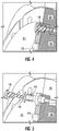
FIG. 4 is an assembled cross-sectional side view of the shield shown inFIG. 3 within the compressor shown inFIGs. 1 and2 . -
FIG. 5 is an exploded cross-sectional side view of the shield shown inFIG. 3 within the compressor shown inFIGs. 1 and2 . - As will be described below, a shield for controlling the cooling within a hermetically cooled motor, and a compressor incorporating the same are provided. The shield makes it possible to prevent, or at least mitigate, the overcooling of the magnetic bearings within a compressor. In certain instances, the shield acts as a protective boundary by restricting the flow of refrigerant from an electric motor of a compressor toward a magnetic bearing of a compressor. By restricting the flow of refrigerant with a shield, cooling of the magnetic bearings within a compressor can be managed without requiring an active control (e.g. actively adjusting the amount of refrigerant being dispersed by one or more jet).
- Although it is envisioned that the
shield 110 could be used in any hermetically cooled motor, for purposes of simplicity and brevity, theshield 110 is described in terms of being used in acompressor 100. For example, acompressor 100 with anelectric motor 130 and a magnetic bearing 120. An exemplary depiction of ashield 110 within acompressor 100 with anelectric motor 130 and amagnetic bearing 120 is shown inFIGs. 1 and2 . Theelectric motor 130 is used by thecompressor 100 for driving arotating shaft 140. Themagnetic bearing 120 is used by thecompressor 100 for magnetically levitating therotating shaft 140. To control the cooling within the within the compressor 100 (e.g. to prevent the overcooling of the magnetic bearing), ashield 110 is configured between theelectric motor 130 and themagnetic bearing 120. - The
shield 110 includes aninsulator 111, at least onefastener aperture 112, and a ventingaperture 113. Theshield 110 is configured such that one side (e.g. the first side 180) is adjacent to theelectric motor 130, and the other side (e.g. the second side 190) is adjacent to themagnetic bearing 120. Theshield 110 is configured to restrict the flow of a working fluid (e.g. refrigerant) between theelectric motor 130 and themagnetic bearing 120. By restricting the flow of the working fluid, theshield 110, in certain instance, helps to prevent, or at least mitigate, overcooling of themagnetic bearing 120 within thecompressor 100. - To facilitate the distribution of the working fluid (e.g. refrigerant) through the
compressor 100, thecompressor 100 may include at least onejet 150. Thejet 150 may be any orifice capable of injecting an effective amount of working fluid into thecompressor 100 to prevent overheating. In certain instances, thecompressor 100 includes at least onejet 150 upstream of theshield 110 and at least onejet 150 downstream of theshield 110. The jet(s) 150 upstream of theshield 110 may be used to distribute the working fluid to cool theelectric motor 130. The jet(s) 150 downstream of theshield 110 may be used to distribute the working fluid to cool themagnetic bearing 120. Theshield 110, by being configured between theelectric motor 130 and themagnetic bearing 120, restricts the flow of the working fluid between theelectric motor 130 andmagnetic bearing 120. By restricting the flow of working fluid through theshield 110, in certain instances, helps to prevent, or at least mitigate, overcooling of themagnetic bearing 120. - In certain instances, the working fluid injected into the
first side 180 and thesecond side 190 of the shield is in a substantially liquid phase. A substantially liquid phase can be interpreted to mean that more of the working fluid is in liquid phase than vapor phase. In some embodiments, theshield 110 allows for the working fluid to flow from thesecond side 190 of theshield 110 to the first side of theshield 180 so that the working fluid can pass to thedrain 131 in theelectric motor 130. In certain instances, the working fluid is R-134A refrigerant. In some embodiments, the compressor is either a centrifugal compressor, an axial compressor, or a scroll compressor. - A perspective view of the
shield 110 is shown inFIG. 3 . Theshield 110 includes aninsulator 111 for restricting the flow of a working fluid (e.g. refrigerant) between afirst side 180 and a second side 190 (shown inFIGs. 1 and2 ). Theshield 110 also includes at least onefastener aperture 112 disposed in theinsulator 111 to enable theinsulator 111 to be secured to themagnetic bearing 120 and/or the bearinghousing 121. To secure theinsulator 111, at least one fastener, for example, one or more shoulder bolts (shown inFIGs. 4 and 5 ), can be inserted through the at least onefastener aperture 112. Theshield 110 additionally includes at least oneventing aperture 113 for controlling a pressure differential between thefirst side 180 and thesecond side 190. - The venting
aperture 113, in certain instances, is provided through use of at least one hole through theinsulator 111. At least one hole may be used to allow the passage of a rotating shaft 140 (shown inFIGs. 1 and2 ). When incorporating a hole for therotating shaft 140, the hole for therotating shaft 140 may be the venting aperture 113 (e.g. enabling the control of the pressure differential between the first side and the second side). For example, the hole used to allow the passage of therotating shaft 140 may be wide enough in diameter to create a gap between theinsulator 111 and therotating shaft 140. This gap, in certain instances, helps to control the pressure differential between thefirst side 180 and thesecond side 190. - It is envisioned that the venting
aperture 113 may be provided through use of any number of holes, spaced in any manner, and configured in any shape (e.g. circular, square, etc.) such that both the working fluid flow and pressure differential can be effectively controlled between eachside shield 110. Effective control of working fluid flow can be viewed as allowing for the working fluid to pass to themagnetic bearings 120 in such a manner that overheating and overcooling are prevented. Effective control of pressure differential can be viewed as preventing a substantial difference in pressure between eachside shield 110. A substantial difference in pressure is one that could adversely affect the structure of the shield. - In certain instances, the
insulator 111 is made of a material with low electrical and thermal conductivity. For example, theinsulator 111 may be made of, at least in part, G10-FR4 (commonly known as "Garolite"). However, it is envisioned that theinsulator 111 may be made of any material capable of restricting the flow of the working fluid. For example, theinsulator 111 may be made of, at least in part, a variety of different plastic materials and/or polymers with low electrical and thermal conductivity. - To allow for the
shield 110 to expand and contract, which is caused by the thermal effects of the working fluid, in certain instances, eachrespective fastener 118 may use aspring washer 114. The use of afastener 118 with aspring washer 114 is shown inFIGs. 4 and 5 . Thespring washer 114 may be any type ofspring washer 114, for example, a Belleville spring washer, a curved spring washer, a finger spring washer, or a wave spring washer. Regardless of the type ofspring washer 114 utilized, in certain instances, thespring washer 114 is used to allow theshield 110 to expand and contract without generating, or at least minimizing, stress near thefastener 118. - As shown in
FIGs. 4 and 5 , in certain instances theshield 110 is secured by passing afastener 118 into themagnetic bearing 120 and/or the bearinghousing 121. To transmit the clamping force from the fastener 118 (e.g. from the head of the shoulder bolt) to thehousing 121, in certain instances, asleeve 115 may be used. Thesleeve 115, in certain instances, is a tube of sufficient length and diameter to allow the passage of thefastener 118. Thissleeve 115, in certain instances, helps reduce the stress on theinsulator 111 caused by the fastener 118 (e.g. if the clamping force of thefastener 118 is directly applied to theinsulator 111 the stress on theinsulator 111 may be comparatively higher relative to the stress on theinsulator 111 when asleeve 115 is used). - As shown in
FIG. 3 , in certain instances, theshield 110 is configured in an annulus shape having anouter diameter 117 and aninner diameter 116. At least onefastener aperture 112, in certain instances, is disposed circumferentially adjacent to theouter diameter 117. At least oneventing aperture 113, in certain instances, is disposed circumferentially adjacent to theinner diameter 116. As described above, the design and configuration of the components of theshield 110, and the positioning within a hermetically cooled motor (e.g. a compressor 100) enable a relatively simplistic technique for preventing, or at least mitigating, overcooling of amagnetic bearing 120. - While the present disclosure has been described with reference to an exemplary embodiment or embodiments, it will be understood by those skilled in the art that various changes may be made and equivalents may be substituted for elements thereof without departing from the scope of the present invention as defined by the claims. In addition, many modifications may be made to adapt a particular situation or material to the teachings of the present disclosure. Therefore, it is intended that the present invention not be limited to the particular embodiment disclosed for carrying out this present disclosure, but that the present invention will include all embodiments falling within the scope of the claims.
- The following clauses recite features of the invention which may or may not presently be claims, but which may serve as basis for amendments and/or one or more divisional applications:
- 1. A shield for controlling the cooling within a hermetically cooled motor, the shield comprising:
- an insulator surface comprising a first side and a second side, the insulator surface configured to restrict the flow of a working fluid;
- at least one fastener aperture disposed in the insulator surface; and
- at least one venting aperture disposed in the insulator surface, the at least one venting aperture configured to control a pressure differential between the first side and the second side.
- 2. The shield of clause 1, wherein the shield comprises an annulus shape having an outer diameter and an inner diameter; and wherein the at least one fastener aperture is disposed circumferentially adjacent to the outer diameter, and the at least one venting aperture is disposed circumferentially adjacent to the inner diameter.
- 3. The shield of clause 1, wherein the insulator surface is comprised of a material with low electrical and thermal conductivity.
- 4. The shield of clause 3, wherein the material is Garolite.
- 5. A compressor comprising:
- an electric motor for driving a rotating shaft;
- a magnetic bearing disposed adjacent to the electric motor,
- a shield disposed between the electric motor and the magnetic bearing, the shield comprising:
- an insulator surface configured to restrict the flow of a working fluid;
- at least one fastener aperture disposed in the insulator surface; and
- at least one venting aperture disposed in the insulator surface, the at least one venting aperture configured to control a pressure differential between the first side and the second side.
- 6. The compressor of clause 5, wherein the shield comprises an annulus shape having an outer diameter and an inner diameter; and wherein the at least one fastener aperture is disposed circumferentially adjacent to the outer diameter, and the at least one venting aperture is disposed circumferentially adjacent to the inner diameter.
- 7. The compressor of clause 6, wherein the shaft passes through the annulus.
- 8. The compressor of clause 6, further comprising a fastening assembly, the fastening assembly configured to secure the shield to the magnetic bearing through at least one of the fastener apertures.
- 9. The compressor of clause 8, wherein the fastening assembly comprises at least one of a fastener, a washer, and a sleeve.
- 10. The compressor of clause 5, further comprising at least one first jet disposed upstream of the shield, and at least one second jet disposed downstream of the shield; the at least one first jet and the at least one second jet are configured to distribute the working fluid.
- 11. The compressor of clause 10, wherein the distributed working fluid is configured to pass through the at least one venting aperture.
- 12. The compressor of clause 10, wherein the at least one first jet is configured to distribute the working fluid to the electric motor.
- 13. The compressor of clause 10, wherein the at least one second jet is configured to distribute the working fluid to the magnetic bearing.
- 14. The compressor of clause 10, wherein the working fluid is in a substantially liquid phase.
- 15. The compressor of clause 10, wherein the working fluid is R-134A refrigerant.
- 16. The compressor of clause 5, wherein the compressor is a centrifugal compressor.
- 17. The compressor of clause 5, wherein the compressor is an axial compressor.
- 18. The compressor of clause 5, wherein the compressor is a scroll compressor.
Claims (15)
- A shield (110) for controlling the cooling within a hermetically cooled motor (130), the shield comprising:an insulator surface (111) comprising a first side (180) and a second side (190), the insulator surface configured to restrict the flow of a working fluid;at least one fastener aperture (112) disposed in the insulator surface (111); andat least one venting aperture (113) disposed in the insulator surface (111), the at least one venting aperture configured to control a pressure differential between the first side (180) and the second side (190).
- The shield (110) of claim 1, wherein the shield comprises an annulus shape having an outer diameter (117) and an inner diameter (116); and wherein the at least one fastener aperture (112) is disposed circumferentially adjacent to the outer diameter (117), and the at least one venting aperture (113) is disposed circumferentially adjacent to the inner diameter (116).
- The shield (110) of claim 1 or 2, wherein the insulator surface (111) is comprised of a material with low electrical and thermal conductivity, optionally wherein the material is Garolite.
- A compressor (100) comprising:an electric motor (130) for driving a rotating shaft (140);a magnetic bearing (120) disposed adjacent to the electric motor (130),the shield (110) of claim 1 disposed between the electric motor (130) and the magnetic bearing (120).
- The compressor of claim 4, wherein the shield (110) comprises an annulus shape having an outer diameter (117) and an inner diameter (116); and wherein the at least one fastener aperture (112) is disposed circumferentially adjacent to the outer diameter (117), and the at least one venting aperture (113) is disposed circumferentially adjacent to the inner diameter (116).
- The compressor (100) of claim 5, wherein the shaft (140) passes through the annulus.
- The compressor (100) of claim 4, 5, or 6, further comprising a fastening assembly, the fastening assembly configured to secure the shield (110) to the magnetic bearing (120) through at least one of the fastener apertures (112).
- The compressor (100) of claim 7, wherein the fastening assembly comprises at least one of a fastener (118), a washer (114), and a sleeve (115).
- The compressor (100) of any of claims 4 to 8, further comprising at least one first jet (150) disposed upstream of the shield (110), and at least one second jet (150) disposed downstream of the shield; the at least one first jet and the at least one second jet are configured to distribute the working fluid.
- The compressor (100) of claim 9, wherein the distributed working fluid is configured to pass through the at least one venting aperture (113).
- The compressor (100) of claim 9 or 10, wherein the at least one first jet (150) is configured to distribute the working fluid to the electric motor (130).
- The compressor (100) of claim 9, 10, or 11, wherein the at least one second jet (150) is configured to distribute the working fluid to the magnetic bearing (120).
- The compressor (100) of any of claims 4 to 12, wherein the working fluid is in a substantially liquid phase.
- The compressor (100) of any of claims 4 to 13, wherein the working fluid is R-134A refrigerant.
- The compressor (100) of any of claims 4 to 14, wherein the compressor is a
centrifugal compressor; or
wherein the compressor is an axial compressor; or wherein the compressor is a scroll compressor.
Applications Claiming Priority (1)
| Application Number | Priority Date | Filing Date | Title |
|---|---|---|---|
| US202062967620P | 2020-01-30 | 2020-01-30 |
Publications (2)
| Publication Number | Publication Date |
|---|---|
| EP3859162A1 true EP3859162A1 (en) | 2021-08-04 |
| EP3859162B1 EP3859162B1 (en) | 2023-11-29 |
Family
ID=74494731
Family Applications (1)
| Application Number | Title | Priority Date | Filing Date |
|---|---|---|---|
| EP21154444.0A Active EP3859162B1 (en) | 2020-01-30 | 2021-01-29 | Magnetic bearing cooling management |
Country Status (4)
| Country | Link |
|---|---|
| US (1) | US11923746B2 (en) |
| EP (1) | EP3859162B1 (en) |
| CN (1) | CN113266605A (en) |
| ES (1) | ES2966986T3 (en) |
Citations (5)
| Publication number | Priority date | Publication date | Assignee | Title |
|---|---|---|---|---|
| US5980218A (en) * | 1996-09-17 | 1999-11-09 | Hitachi, Ltd. | Multi-stage compressor having first and second passages for cooling a motor during load and non-load operation |
| EP1467104A1 (en) * | 2003-04-11 | 2004-10-13 | Thermodyn | Compressor unit with assisted cooling |
| US20050093385A1 (en) * | 2003-09-15 | 2005-05-05 | Linde Aktiengesellschaft | Electrical machine with cooling system |
| US20120107105A1 (en) * | 2009-07-13 | 2012-05-03 | Gerard Korenblik | Turbocompressor assembly with a cooling system |
| US20150276282A1 (en) * | 2012-12-07 | 2015-10-01 | Trane International Inc. | Motor cooling system for chillers |
Family Cites Families (13)
| Publication number | Priority date | Publication date | Assignee | Title |
|---|---|---|---|---|
| GB827566A (en) * | 1956-12-03 | 1960-02-10 | Fuller Co | Improvements in centrifugal fluid fans |
| JP2001218425A (en) * | 2000-02-07 | 2001-08-10 | Thk Co Ltd | Electric motor having rotor cooling function |
| US6933638B2 (en) | 2003-10-30 | 2005-08-23 | A. O. Smith Corporation | Electric motor having a reverse air flow cooling system |
| JP5001665B2 (en) * | 2007-01-29 | 2012-08-15 | 株式会社キャップ | Fan for blowing high temperature fuel gas in solid oxide fuel cells |
| JP2009062848A (en) * | 2007-09-05 | 2009-03-26 | Ntn Corp | Motor integrated type magnetic bearing device |
| US8827651B2 (en) | 2010-11-01 | 2014-09-09 | Rolls-Royce Plc | Annulus filler |
| CN205025807U (en) | 2015-10-14 | 2016-02-10 | 重庆美的通用制冷设备有限公司 | Bearing assembly for centrifugal compressor |
| KR102103041B1 (en) * | 2015-10-22 | 2020-04-22 | 한국기계연구원 | Turbo compressor |
| US10724546B2 (en) * | 2016-08-05 | 2020-07-28 | Daikin Applied Americas Inc. | Centrifugal compressor having a casing with an adjustable clearance and connections for a variable flow rate cooling medium, impeller clearance control apparatus for centrifugal compressor, and impeller clearance control method for centrifugal compressor |
| CN106246606A (en) * | 2016-09-19 | 2016-12-21 | 珠海格力电器股份有限公司 | Compressor and air conditioner |
| WO2018162085A1 (en) * | 2017-03-10 | 2018-09-13 | Brose Fahrzeugteile GmbH & Co. Kommanditgesellschaft, Würzburg | Electrical refrigerant drive |
| KR20180118455A (en) * | 2017-04-21 | 2018-10-31 | 엘지전자 주식회사 | Turbo compressor |
| CN209340162U (en) * | 2018-12-25 | 2019-09-03 | 珠海格力电器股份有限公司 | Compressor and air conditioning unit |
-
2021
- 2021-01-06 US US17/248,031 patent/US11923746B2/en active Active
- 2021-01-29 CN CN202110124988.2A patent/CN113266605A/en active Pending
- 2021-01-29 EP EP21154444.0A patent/EP3859162B1/en active Active
- 2021-01-29 ES ES21154444T patent/ES2966986T3/en active Active
Patent Citations (5)
| Publication number | Priority date | Publication date | Assignee | Title |
|---|---|---|---|---|
| US5980218A (en) * | 1996-09-17 | 1999-11-09 | Hitachi, Ltd. | Multi-stage compressor having first and second passages for cooling a motor during load and non-load operation |
| EP1467104A1 (en) * | 2003-04-11 | 2004-10-13 | Thermodyn | Compressor unit with assisted cooling |
| US20050093385A1 (en) * | 2003-09-15 | 2005-05-05 | Linde Aktiengesellschaft | Electrical machine with cooling system |
| US20120107105A1 (en) * | 2009-07-13 | 2012-05-03 | Gerard Korenblik | Turbocompressor assembly with a cooling system |
| US20150276282A1 (en) * | 2012-12-07 | 2015-10-01 | Trane International Inc. | Motor cooling system for chillers |
Also Published As
| Publication number | Publication date |
|---|---|
| CN113266605A (en) | 2021-08-17 |
| US20210242744A1 (en) | 2021-08-05 |
| EP3859162B1 (en) | 2023-11-29 |
| US11923746B2 (en) | 2024-03-05 |
| ES2966986T3 (en) | 2024-04-25 |
Similar Documents
| Publication | Publication Date | Title |
|---|---|---|
| US5658127A (en) | Seal element cooling in high speed mechanical face seals | |
| US9450474B2 (en) | Active cooling of a motor | |
| US9650906B2 (en) | Slotted labyrinth seal | |
| EP1623122B8 (en) | Automotive engine-cooling fan assembly | |
| US8593022B2 (en) | Electric motor with heat dissipation structure | |
| US8740562B2 (en) | Axial fan and method of manufacturing the same | |
| KR100609655B1 (en) | Fan drive assembly | |
| US20220294304A1 (en) | Electric machine | |
| US8109743B2 (en) | Axial flow fan unit | |
| BR102015019631A2 (en) | electric cooling pump | |
| WO2013043495A1 (en) | Tilt pad bearing with through-pivot lubrication | |
| US6847140B2 (en) | Fluid barrier for motor rotor | |
| EP4264070B1 (en) | Foil bearing assembly including segmented inner foils assembly and compressor including this bearing assembly | |
| US20020141871A1 (en) | Axial-flow fan having inner and outer blades | |
| US10655532B2 (en) | Electric charging device with rotor cooling | |
| KR20000062989A (en) | Improvements in pumps | |
| CN114759734A (en) | Oil cooling structure for magnet of motor and motor | |
| KR20250121407A (en) | Foil bearing assembly comprising a perforated inner foil assembly and a compressor comprising the same | |
| EP3859162B1 (en) | Magnetic bearing cooling management | |
| CA2961893C (en) | External fan and drive end housing for an air cooled alternator | |
| US11226000B2 (en) | Thrust supporting apparatus | |
| US4250417A (en) | Air deflector for electric motor | |
| KR102777799B1 (en) | Radial Force Support Apparatus | |
| US20190170214A1 (en) | Heat dissipation structures for crankshaft dampers | |
| KR101618716B1 (en) | Coil support for rotating electrical machine |
Legal Events
| Date | Code | Title | Description |
|---|---|---|---|
| PUAI | Public reference made under article 153(3) epc to a published international application that has entered the european phase |
Free format text: ORIGINAL CODE: 0009012 |
|
| STAA | Information on the status of an ep patent application or granted ep patent |
Free format text: STATUS: THE APPLICATION HAS BEEN PUBLISHED |
|
| AK | Designated contracting states |
Kind code of ref document: A1 Designated state(s): AL AT BE BG CH CY CZ DE DK EE ES FI FR GB GR HR HU IE IS IT LI LT LU LV MC MK MT NL NO PL PT RO RS SE SI SK SM TR |
|
| STAA | Information on the status of an ep patent application or granted ep patent |
Free format text: STATUS: REQUEST FOR EXAMINATION WAS MADE |
|
| 17P | Request for examination filed |
Effective date: 20220202 |
|
| RBV | Designated contracting states (corrected) |
Designated state(s): AL AT BE BG CH CY CZ DE DK EE ES FI FR GB GR HR HU IE IS IT LI LT LU LV MC MK MT NL NO PL PT RO RS SE SI SK SM TR |
|
| GRAP | Despatch of communication of intention to grant a patent |
Free format text: ORIGINAL CODE: EPIDOSNIGR1 |
|
| STAA | Information on the status of an ep patent application or granted ep patent |
Free format text: STATUS: GRANT OF PATENT IS INTENDED |
|
| INTG | Intention to grant announced |
Effective date: 20230612 |
|
| P01 | Opt-out of the competence of the unified patent court (upc) registered |
Effective date: 20230527 |
|
| GRAS | Grant fee paid |
Free format text: ORIGINAL CODE: EPIDOSNIGR3 |
|
| GRAA | (expected) grant |
Free format text: ORIGINAL CODE: 0009210 |
|
| STAA | Information on the status of an ep patent application or granted ep patent |
Free format text: STATUS: THE PATENT HAS BEEN GRANTED |
|
| AK | Designated contracting states |
Kind code of ref document: B1 Designated state(s): AL AT BE BG CH CY CZ DE DK EE ES FI FR GB GR HR HU IE IS IT LI LT LU LV MC MK MT NL NO PL PT RO RS SE SI SK SM TR |
|
| REG | Reference to a national code |
Ref country code: GB Ref legal event code: FG4D |
|
| REG | Reference to a national code |
Ref country code: CH Ref legal event code: EP |
|
| REG | Reference to a national code |
Ref country code: IE Ref legal event code: FG4D |
|
| REG | Reference to a national code |
Ref country code: DE Ref legal event code: R096 Ref document number: 602021007144 Country of ref document: DE |
|
| REG | Reference to a national code |
Ref country code: NL Ref legal event code: FP |
|
| REG | Reference to a national code |
Ref country code: LT Ref legal event code: MG9D |
|
| PG25 | Lapsed in a contracting state [announced via postgrant information from national office to epo] |
Ref country code: GR Free format text: LAPSE BECAUSE OF FAILURE TO SUBMIT A TRANSLATION OF THE DESCRIPTION OR TO PAY THE FEE WITHIN THE PRESCRIBED TIME-LIMIT Effective date: 20240301 |
|
| PG25 | Lapsed in a contracting state [announced via postgrant information from national office to epo] |
Ref country code: IS Free format text: LAPSE BECAUSE OF FAILURE TO SUBMIT A TRANSLATION OF THE DESCRIPTION OR TO PAY THE FEE WITHIN THE PRESCRIBED TIME-LIMIT Effective date: 20240329 |
|
| PG25 | Lapsed in a contracting state [announced via postgrant information from national office to epo] |
Ref country code: LT Free format text: LAPSE BECAUSE OF FAILURE TO SUBMIT A TRANSLATION OF THE DESCRIPTION OR TO PAY THE FEE WITHIN THE PRESCRIBED TIME-LIMIT Effective date: 20231129 |
|
| REG | Reference to a national code |
Ref country code: ES Ref legal event code: FG2A Ref document number: 2966986 Country of ref document: ES Kind code of ref document: T3 Effective date: 20240425 |
|
| PG25 | Lapsed in a contracting state [announced via postgrant information from national office to epo] |
Ref country code: LT Free format text: LAPSE BECAUSE OF FAILURE TO SUBMIT A TRANSLATION OF THE DESCRIPTION OR TO PAY THE FEE WITHIN THE PRESCRIBED TIME-LIMIT Effective date: 20231129 Ref country code: IS Free format text: LAPSE BECAUSE OF FAILURE TO SUBMIT A TRANSLATION OF THE DESCRIPTION OR TO PAY THE FEE WITHIN THE PRESCRIBED TIME-LIMIT Effective date: 20240329 Ref country code: GR Free format text: LAPSE BECAUSE OF FAILURE TO SUBMIT A TRANSLATION OF THE DESCRIPTION OR TO PAY THE FEE WITHIN THE PRESCRIBED TIME-LIMIT Effective date: 20240301 Ref country code: BG Free format text: LAPSE BECAUSE OF FAILURE TO SUBMIT A TRANSLATION OF THE DESCRIPTION OR TO PAY THE FEE WITHIN THE PRESCRIBED TIME-LIMIT Effective date: 20240229 |
|
| REG | Reference to a national code |
Ref country code: AT Ref legal event code: MK05 Ref document number: 1636392 Country of ref document: AT Kind code of ref document: T Effective date: 20231129 |
|
| PG25 | Lapsed in a contracting state [announced via postgrant information from national office to epo] |
Ref country code: SE Free format text: LAPSE BECAUSE OF FAILURE TO SUBMIT A TRANSLATION OF THE DESCRIPTION OR TO PAY THE FEE WITHIN THE PRESCRIBED TIME-LIMIT Effective date: 20231129 Ref country code: RS Free format text: LAPSE BECAUSE OF FAILURE TO SUBMIT A TRANSLATION OF THE DESCRIPTION OR TO PAY THE FEE WITHIN THE PRESCRIBED TIME-LIMIT Effective date: 20231129 Ref country code: PL Free format text: LAPSE BECAUSE OF FAILURE TO SUBMIT A TRANSLATION OF THE DESCRIPTION OR TO PAY THE FEE WITHIN THE PRESCRIBED TIME-LIMIT Effective date: 20231129 Ref country code: NO Free format text: LAPSE BECAUSE OF FAILURE TO SUBMIT A TRANSLATION OF THE DESCRIPTION OR TO PAY THE FEE WITHIN THE PRESCRIBED TIME-LIMIT Effective date: 20240229 Ref country code: LV Free format text: LAPSE BECAUSE OF FAILURE TO SUBMIT A TRANSLATION OF THE DESCRIPTION OR TO PAY THE FEE WITHIN THE PRESCRIBED TIME-LIMIT Effective date: 20231129 Ref country code: HR Free format text: LAPSE BECAUSE OF FAILURE TO SUBMIT A TRANSLATION OF THE DESCRIPTION OR TO PAY THE FEE WITHIN THE PRESCRIBED TIME-LIMIT Effective date: 20231129 |
|
| PG25 | Lapsed in a contracting state [announced via postgrant information from national office to epo] |
Ref country code: DK Free format text: LAPSE BECAUSE OF FAILURE TO SUBMIT A TRANSLATION OF THE DESCRIPTION OR TO PAY THE FEE WITHIN THE PRESCRIBED TIME-LIMIT Effective date: 20231129 |
|
| PG25 | Lapsed in a contracting state [announced via postgrant information from national office to epo] |
Ref country code: CZ Free format text: LAPSE BECAUSE OF FAILURE TO SUBMIT A TRANSLATION OF THE DESCRIPTION OR TO PAY THE FEE WITHIN THE PRESCRIBED TIME-LIMIT Effective date: 20231129 Ref country code: AT Free format text: LAPSE BECAUSE OF FAILURE TO SUBMIT A TRANSLATION OF THE DESCRIPTION OR TO PAY THE FEE WITHIN THE PRESCRIBED TIME-LIMIT Effective date: 20231129 |
|
| PG25 | Lapsed in a contracting state [announced via postgrant information from national office to epo] |
Ref country code: SK Free format text: LAPSE BECAUSE OF FAILURE TO SUBMIT A TRANSLATION OF THE DESCRIPTION OR TO PAY THE FEE WITHIN THE PRESCRIBED TIME-LIMIT Effective date: 20231129 |
|
| PG25 | Lapsed in a contracting state [announced via postgrant information from national office to epo] |
Ref country code: SM Free format text: LAPSE BECAUSE OF FAILURE TO SUBMIT A TRANSLATION OF THE DESCRIPTION OR TO PAY THE FEE WITHIN THE PRESCRIBED TIME-LIMIT Effective date: 20231129 Ref country code: SK Free format text: LAPSE BECAUSE OF FAILURE TO SUBMIT A TRANSLATION OF THE DESCRIPTION OR TO PAY THE FEE WITHIN THE PRESCRIBED TIME-LIMIT Effective date: 20231129 Ref country code: RO Free format text: LAPSE BECAUSE OF FAILURE TO SUBMIT A TRANSLATION OF THE DESCRIPTION OR TO PAY THE FEE WITHIN THE PRESCRIBED TIME-LIMIT Effective date: 20231129 Ref country code: EE Free format text: LAPSE BECAUSE OF FAILURE TO SUBMIT A TRANSLATION OF THE DESCRIPTION OR TO PAY THE FEE WITHIN THE PRESCRIBED TIME-LIMIT Effective date: 20231129 Ref country code: DK Free format text: LAPSE BECAUSE OF FAILURE TO SUBMIT A TRANSLATION OF THE DESCRIPTION OR TO PAY THE FEE WITHIN THE PRESCRIBED TIME-LIMIT Effective date: 20231129 Ref country code: CZ Free format text: LAPSE BECAUSE OF FAILURE TO SUBMIT A TRANSLATION OF THE DESCRIPTION OR TO PAY THE FEE WITHIN THE PRESCRIBED TIME-LIMIT Effective date: 20231129 Ref country code: AT Free format text: LAPSE BECAUSE OF FAILURE TO SUBMIT A TRANSLATION OF THE DESCRIPTION OR TO PAY THE FEE WITHIN THE PRESCRIBED TIME-LIMIT Effective date: 20231129 |
|
| PG25 | Lapsed in a contracting state [announced via postgrant information from national office to epo] |
Ref country code: PT Free format text: LAPSE BECAUSE OF FAILURE TO SUBMIT A TRANSLATION OF THE DESCRIPTION OR TO PAY THE FEE WITHIN THE PRESCRIBED TIME-LIMIT Effective date: 20240401 |
|
| PG25 | Lapsed in a contracting state [announced via postgrant information from national office to epo] |
Ref country code: MC Free format text: LAPSE BECAUSE OF FAILURE TO SUBMIT A TRANSLATION OF THE DESCRIPTION OR TO PAY THE FEE WITHIN THE PRESCRIBED TIME-LIMIT Effective date: 20231129 |
|
| PG25 | Lapsed in a contracting state [announced via postgrant information from national office to epo] |
Ref country code: PT Free format text: LAPSE BECAUSE OF FAILURE TO SUBMIT A TRANSLATION OF THE DESCRIPTION OR TO PAY THE FEE WITHIN THE PRESCRIBED TIME-LIMIT Effective date: 20240401 Ref country code: MC Free format text: LAPSE BECAUSE OF FAILURE TO SUBMIT A TRANSLATION OF THE DESCRIPTION OR TO PAY THE FEE WITHIN THE PRESCRIBED TIME-LIMIT Effective date: 20231129 |
|
| REG | Reference to a national code |
Ref country code: DE Ref legal event code: R097 Ref document number: 602021007144 Country of ref document: DE Ref country code: CH Ref legal event code: PL |
|
| PG25 | Lapsed in a contracting state [announced via postgrant information from national office to epo] |
Ref country code: LU Free format text: LAPSE BECAUSE OF NON-PAYMENT OF DUE FEES Effective date: 20240129 |
|
| PG25 | Lapsed in a contracting state [announced via postgrant information from national office to epo] |
Ref country code: LU Free format text: LAPSE BECAUSE OF NON-PAYMENT OF DUE FEES Effective date: 20240129 |
|
| PLBE | No opposition filed within time limit |
Free format text: ORIGINAL CODE: 0009261 |
|
| STAA | Information on the status of an ep patent application or granted ep patent |
Free format text: STATUS: NO OPPOSITION FILED WITHIN TIME LIMIT |
|
| PG25 | Lapsed in a contracting state [announced via postgrant information from national office to epo] |
Ref country code: CH Free format text: LAPSE BECAUSE OF NON-PAYMENT OF DUE FEES Effective date: 20240131 |
|
| PG25 | Lapsed in a contracting state [announced via postgrant information from national office to epo] |
Ref country code: SI Free format text: LAPSE BECAUSE OF FAILURE TO SUBMIT A TRANSLATION OF THE DESCRIPTION OR TO PAY THE FEE WITHIN THE PRESCRIBED TIME-LIMIT Effective date: 20231129 |
|
| PG25 | Lapsed in a contracting state [announced via postgrant information from national office to epo] |
Ref country code: SI Free format text: LAPSE BECAUSE OF FAILURE TO SUBMIT A TRANSLATION OF THE DESCRIPTION OR TO PAY THE FEE WITHIN THE PRESCRIBED TIME-LIMIT Effective date: 20231129 Ref country code: CH Free format text: LAPSE BECAUSE OF NON-PAYMENT OF DUE FEES Effective date: 20240131 |
|
| 26N | No opposition filed |
Effective date: 20240830 |
|
| PGFP | Annual fee paid to national office [announced via postgrant information from national office to epo] |
Ref country code: NL Payment date: 20241219 Year of fee payment: 5 Ref country code: BE Payment date: 20241218 Year of fee payment: 5 |
|
| PG25 | Lapsed in a contracting state [announced via postgrant information from national office to epo] |
Ref country code: IE Free format text: LAPSE BECAUSE OF NON-PAYMENT OF DUE FEES Effective date: 20240129 |
|
| PG25 | Lapsed in a contracting state [announced via postgrant information from national office to epo] |
Ref country code: IE Free format text: LAPSE BECAUSE OF NON-PAYMENT OF DUE FEES Effective date: 20240129 |
|
| PGFP | Annual fee paid to national office [announced via postgrant information from national office to epo] |
Ref country code: ES Payment date: 20250203 Year of fee payment: 5 |
|
| PGFP | Annual fee paid to national office [announced via postgrant information from national office to epo] |
Ref country code: IT Payment date: 20250107 Year of fee payment: 5 |
|
| PG25 | Lapsed in a contracting state [announced via postgrant information from national office to epo] |
Ref country code: CY Free format text: LAPSE BECAUSE OF FAILURE TO SUBMIT A TRANSLATION OF THE DESCRIPTION OR TO PAY THE FEE WITHIN THE PRESCRIBED TIME-LIMIT; INVALID AB INITIO Effective date: 20210129 |
|
| PG25 | Lapsed in a contracting state [announced via postgrant information from national office to epo] |
Ref country code: HU Free format text: LAPSE BECAUSE OF FAILURE TO SUBMIT A TRANSLATION OF THE DESCRIPTION OR TO PAY THE FEE WITHIN THE PRESCRIBED TIME-LIMIT; INVALID AB INITIO Effective date: 20210129 |
|
| PG25 | Lapsed in a contracting state [announced via postgrant information from national office to epo] |
Ref country code: FI Free format text: LAPSE BECAUSE OF FAILURE TO SUBMIT A TRANSLATION OF THE DESCRIPTION OR TO PAY THE FEE WITHIN THE PRESCRIBED TIME-LIMIT Effective date: 20231129 |
|
| PG25 | Lapsed in a contracting state [announced via postgrant information from national office to epo] |
Ref country code: TR Free format text: LAPSE BECAUSE OF FAILURE TO SUBMIT A TRANSLATION OF THE DESCRIPTION OR TO PAY THE FEE WITHIN THE PRESCRIBED TIME-LIMIT Effective date: 20231129 |
|
| PGFP | Annual fee paid to national office [announced via postgrant information from national office to epo] |
Ref country code: GB Payment date: 20251220 Year of fee payment: 6 |
|
| PGFP | Annual fee paid to national office [announced via postgrant information from national office to epo] |
Ref country code: FR Payment date: 20251217 Year of fee payment: 6 |
|
| PGFP | Annual fee paid to national office [announced via postgrant information from national office to epo] |
Ref country code: DE Payment date: 20251217 Year of fee payment: 6 |