EP3859161A1 - Rotary machine - Google Patents
Rotary machine Download PDFInfo
- Publication number
- EP3859161A1 EP3859161A1 EP21153407.8A EP21153407A EP3859161A1 EP 3859161 A1 EP3859161 A1 EP 3859161A1 EP 21153407 A EP21153407 A EP 21153407A EP 3859161 A1 EP3859161 A1 EP 3859161A1
- Authority
- EP
- European Patent Office
- Prior art keywords
- section
- expansion
- compression
- casing
- compression section
- Prior art date
- Legal status (The legal status is an assumption and is not a legal conclusion. Google has not performed a legal analysis and makes no representation as to the accuracy of the status listed.)
- Granted
Links
Images


Classifications
-
- F—MECHANICAL ENGINEERING; LIGHTING; HEATING; WEAPONS; BLASTING
- F04—POSITIVE - DISPLACEMENT MACHINES FOR LIQUIDS; PUMPS FOR LIQUIDS OR ELASTIC FLUIDS
- F04D—NON-POSITIVE-DISPLACEMENT PUMPS
- F04D17/00—Radial-flow pumps, e.g. centrifugal pumps; Helico-centrifugal pumps
- F04D17/08—Centrifugal pumps
- F04D17/10—Centrifugal pumps for compressing or evacuating
- F04D17/12—Multi-stage pumps
- F04D17/122—Multi-stage pumps the individual rotor discs being, one for each stage, on a common shaft and axially spaced, e.g. conventional centrifugal multi- stage compressors
-
- F—MECHANICAL ENGINEERING; LIGHTING; HEATING; WEAPONS; BLASTING
- F04—POSITIVE - DISPLACEMENT MACHINES FOR LIQUIDS; PUMPS FOR LIQUIDS OR ELASTIC FLUIDS
- F04D—NON-POSITIVE-DISPLACEMENT PUMPS
- F04D29/00—Details, component parts, or accessories
- F04D29/40—Casings; Connections of working fluid
- F04D29/52—Casings; Connections of working fluid for axial pumps
-
- F—MECHANICAL ENGINEERING; LIGHTING; HEATING; WEAPONS; BLASTING
- F01—MACHINES OR ENGINES IN GENERAL; ENGINE PLANTS IN GENERAL; STEAM ENGINES
- F01D—NON-POSITIVE DISPLACEMENT MACHINES OR ENGINES, e.g. STEAM TURBINES
- F01D5/00—Blades; Blade-carrying members; Heating, heat-insulating, cooling or antivibration means on the blades or the members
- F01D5/02—Blade-carrying members, e.g. rotors
- F01D5/027—Arrangements for balancing
-
- F—MECHANICAL ENGINEERING; LIGHTING; HEATING; WEAPONS; BLASTING
- F01—MACHINES OR ENGINES IN GENERAL; ENGINE PLANTS IN GENERAL; STEAM ENGINES
- F01D—NON-POSITIVE DISPLACEMENT MACHINES OR ENGINES, e.g. STEAM TURBINES
- F01D25/00—Component parts, details, or accessories, not provided for in, or of interest apart from, other groups
- F01D25/16—Arrangement of bearings; Supporting or mounting bearings in casings
-
- F—MECHANICAL ENGINEERING; LIGHTING; HEATING; WEAPONS; BLASTING
- F01—MACHINES OR ENGINES IN GENERAL; ENGINE PLANTS IN GENERAL; STEAM ENGINES
- F01D—NON-POSITIVE DISPLACEMENT MACHINES OR ENGINES, e.g. STEAM TURBINES
- F01D5/00—Blades; Blade-carrying members; Heating, heat-insulating, cooling or antivibration means on the blades or the members
- F01D5/02—Blade-carrying members, e.g. rotors
- F01D5/04—Blade-carrying members, e.g. rotors for radial-flow machines or engines
- F01D5/043—Blade-carrying members, e.g. rotors for radial-flow machines or engines of the axial inlet- radial outlet, or vice versa, type
-
- F—MECHANICAL ENGINEERING; LIGHTING; HEATING; WEAPONS; BLASTING
- F04—POSITIVE - DISPLACEMENT MACHINES FOR LIQUIDS; PUMPS FOR LIQUIDS OR ELASTIC FLUIDS
- F04D—NON-POSITIVE-DISPLACEMENT PUMPS
- F04D25/00—Pumping installations or systems
- F04D25/02—Units comprising pumps and their driving means
- F04D25/024—Units comprising pumps and their driving means the driving means being assisted by a power recovery turbine
-
- F—MECHANICAL ENGINEERING; LIGHTING; HEATING; WEAPONS; BLASTING
- F04—POSITIVE - DISPLACEMENT MACHINES FOR LIQUIDS; PUMPS FOR LIQUIDS OR ELASTIC FLUIDS
- F04D—NON-POSITIVE-DISPLACEMENT PUMPS
- F04D29/00—Details, component parts, or accessories
- F04D29/04—Shafts or bearings, or assemblies thereof
- F04D29/041—Axial thrust balancing
- F04D29/0413—Axial thrust balancing hydrostatic; hydrodynamic thrust bearings
-
- F—MECHANICAL ENGINEERING; LIGHTING; HEATING; WEAPONS; BLASTING
- F04—POSITIVE - DISPLACEMENT MACHINES FOR LIQUIDS; PUMPS FOR LIQUIDS OR ELASTIC FLUIDS
- F04D—NON-POSITIVE-DISPLACEMENT PUMPS
- F04D29/00—Details, component parts, or accessories
- F04D29/05—Shafts or bearings, or assemblies thereof, specially adapted for elastic fluid pumps
- F04D29/051—Axial thrust balancing
-
- F—MECHANICAL ENGINEERING; LIGHTING; HEATING; WEAPONS; BLASTING
- F04—POSITIVE - DISPLACEMENT MACHINES FOR LIQUIDS; PUMPS FOR LIQUIDS OR ELASTIC FLUIDS
- F04D—NON-POSITIVE-DISPLACEMENT PUMPS
- F04D29/00—Details, component parts, or accessories
- F04D29/05—Shafts or bearings, or assemblies thereof, specially adapted for elastic fluid pumps
- F04D29/056—Bearings
-
- F—MECHANICAL ENGINEERING; LIGHTING; HEATING; WEAPONS; BLASTING
- F04—POSITIVE - DISPLACEMENT MACHINES FOR LIQUIDS; PUMPS FOR LIQUIDS OR ELASTIC FLUIDS
- F04D—NON-POSITIVE-DISPLACEMENT PUMPS
- F04D29/00—Details, component parts, or accessories
- F04D29/26—Rotors specially for elastic fluids
- F04D29/28—Rotors specially for elastic fluids for centrifugal or helico-centrifugal pumps for radial-flow or helico-centrifugal pumps
- F04D29/284—Rotors specially for elastic fluids for centrifugal or helico-centrifugal pumps for radial-flow or helico-centrifugal pumps for compressors
- F04D29/286—Rotors specially for elastic fluids for centrifugal or helico-centrifugal pumps for radial-flow or helico-centrifugal pumps for compressors multi-stage rotors
-
- F—MECHANICAL ENGINEERING; LIGHTING; HEATING; WEAPONS; BLASTING
- F04—POSITIVE - DISPLACEMENT MACHINES FOR LIQUIDS; PUMPS FOR LIQUIDS OR ELASTIC FLUIDS
- F04D—NON-POSITIVE-DISPLACEMENT PUMPS
- F04D29/00—Details, component parts, or accessories
- F04D29/40—Casings; Connections of working fluid
- F04D29/42—Casings; Connections of working fluid for radial or helico-centrifugal pumps
- F04D29/4206—Casings; Connections of working fluid for radial or helico-centrifugal pumps especially adapted for elastic fluid pumps
-
- F—MECHANICAL ENGINEERING; LIGHTING; HEATING; WEAPONS; BLASTING
- F04—POSITIVE - DISPLACEMENT MACHINES FOR LIQUIDS; PUMPS FOR LIQUIDS OR ELASTIC FLUIDS
- F04D—NON-POSITIVE-DISPLACEMENT PUMPS
- F04D29/00—Details, component parts, or accessories
- F04D29/58—Cooling; Heating; Diminishing heat transfer
Definitions
- the present disclosure relates to a rotary machine.
- United States Patent Application, Publication No. 2013/0091869 discloses a rotary machine (integral compression expander) having a configuration where a compression section that has an impeller compressing a fluid and an expansion section that has an impeller expanding the fluid are provided on one rotary shaft in a casing.
- the rotary shaft is supported to be rotatable about an axis by a pair of bearings.
- the impeller of the compression section is fixed to the rotary shaft between the pair of bearings.
- There is one impeller for the expansion section and is disposed such that one of the pair of bearings is interposed between the impeller of the expansion section and the impeller of the compression section. That is, the impeller of the expansion section is disposed to overhang at a position deviated to an outer side from between the pair of bearings, not between the pair of bearings.
- each impeller is a heavy object.
- the rotor dynamics of the rotary shaft decline in a configuration where the impeller of the expansion section is fixed to the rotary shaft at a position deviated to the outer side from between the pair of bearings.
- the present disclosure provides a rotary machine that can improve the rotor dynamics of a rotary shaft.
- a rotary machine including a rotary shaft that is configured to rotate about an axis, a casing that covers the rotary shaft, a pair of radial bearings that is fixed to the casing and supports the rotary shaft to be rotatable about the axis, a compression section that is disposed between the pair of radial bearings in an axial direction, in which the axis extends, in the casing and is configured to compress a fluid introduced from an outside of the casing, an expansion section that is disposed side by side with the compression section, between the pair of radial bearings in the axial direction, in the casing and is configured to expand a fluid introduced from the outside of the casing, and a thrust bearing that is disposed at a position close to a first end portion or a second end portion of the rotary shaft in the axial direction with respect to the compression section and the expansion section and supports the rotary shaft in the axial direction.
- the compression section includes at least one compression impeller that is fixed to the rotary shaft and is configured to rotate integrally with the rotary shaft to compress the fluid which has flowed inside.
- the expansion section includes at least one expansion impeller that is fixed to the rotary shaft and is configured to rotate integrally with the rotary shaft to expand the fluid which has flowed inside.
- the casing has a compression section suction port that is configured to cause the fluid, of which a pressure is lowest in the compression section, to be introduced into the compression section, a compression section discharge port that is configured to cause the fluid, which is compressed by the compression section and has a highest pressure in the compression section, to be exhausted to an outside of the casing, an expansion section suction port that is configured to cause the fluid, of which a pressure is highest in the expansion section, to be introduced into the expansion section, and an expansion section discharge port that is configured to cause the fluid, which is expanded by the expansion section and has a lowest pressure in the expansion section, to be exhausted to the outside of the casing.
- the compression section suction port is disposed at a position closest to the first end portion in the axial direction
- the expansion section discharge port is disposed at a position closest to the second end portion in the axial direction.
- a rotary machine 1 is a so-called compander including a compression section 5 that functions as a compressor compressing a gas G and an expansion section 6 that functions as an expander expanding the gas G.
- the rotary machine 1 mainly includes a rotary shaft 2, a casing 3, a pair of radial bearings 4A and 4B, the compression section 5, the expansion section 6, and a thrust bearing 9.
- the casing 3 forms the outer shell of the rotary machine 1.
- the casing 3 is formed in a tubular shape extending in an axial direction Da in which an axis O of the rotary shaft 2 extends.
- the casing 3 covers part of the rotary shaft 2, the pair of radial bearings 4A and 4B, the compression section 5, and the expansion section 6.
- the casing 3 has a compression section suction port 33, a compression section discharge port 34, an expansion section suction port 35, and an expansion section discharge port 36.
- the compression section suction port 33 is an inlet nozzle for introducing the gas (fluid) G from a gas supply source (not illustrated) outside the casing 3 into the compression section 5 inside the casing 3.
- the gas G having the lowest pressure in the compression section 5 passes through the compression section suction port 33.
- the compression section discharge port 34 is an outlet nozzle for exhausting the gas G compressed by the compression section 5 to the outside of the casing 3.
- the gas G, which is compressed by the compression section 5 and has the highest pressure in the compression section 5, passes through the compression section discharge port 34.
- the expansion section suction port 35 is an inlet nozzle for introducing the gas G into the expansion section 6.
- the gas G having the highest pressure in the expansion section 6 passes through the expansion section suction port 35.
- the expansion section discharge port 36 is an outlet nozzle for exhausting the gas G expanded by the expansion section 6 to the outside of the casing 3.
- the gas G, which is expanded by the expansion section 6 and has the lowest pressure in the expansion section 6, passes through the expansion section discharge port 36
- the compression section suction port 33, the compression section discharge port 34, the expansion section suction port 35, and the expansion section discharge port 36 are disposed side by side in this order in the axial direction Da from a first end portion 2a of the rotary shaft 2 toward a second end portion 2b of the rotary shaft 2. That is, among the compression section suction port 33, the compression section discharge port 34, the expansion section suction port 35, and the expansion section discharge port 36, the compression section suction port 33 is disposed at a position closest to the first end portion 2a of the rotary shaft 2 in the axial direction Da.
- the expansion section discharge port 36 is disposed at a position closest to the second end portion 2b of the rotary shaft 2 in the axial direction Da.
- the compression section discharge port 34 and the expansion section suction port 35 are disposed at positions closest to each other in the axial direction Da.
- the pair of radial bearings 4A and 4B is fixed to the casing 3.
- the pair of radial bearings 4A and 4B supports the rotary shaft 2 to be rotatable about the axis O.
- the pair of radial bearings 4A and 4B is disposed with an interval in the axial direction Da in the casing 3.
- the radial bearing (first radial bearing) 4A is disposed on a first side Da1 in the axial direction Da in the casing 3.
- the radial bearing (second radial bearing) 4B is disposed on a second side Da2 in the axial direction Da in the casing 3.
- the first side Da1 in the axial direction Da is a side in the axial direction Da, on which the first end portion 2a of the rotary shaft is disposed with respect to the second end portion 2b of the rotary shaft.
- the second side Da2 in the axial direction Da is a side in the axial direction Da, on which the second end portion 2b of the rotary shaft 2 is disposed with respect to the first end portion 2a of the rotary shaft 2. Therefore, the radial bearing 4A is disposed at a position close to the first end portion 2a of the rotary shaft 2.
- the radial bearing 4B is disposed at a position close to the second end portion 2b of the rotary shaft 2.
- the thrust bearing 9 supports the rotary shaft in the axial direction Da.
- the thrust bearing 9 is disposed at a position close to the first end portion 2a or the second end portion 2b of the rotary shaft in the axial direction Da compared to the compression section 5 and the expansion section 6.
- the thrust bearing 9 of the present embodiment is disposed at a position close to the radial bearing 4A. Specifically, the thrust bearing 9 is disposed between the first end portion 2a and the radial bearing 4A in the axial direction Da.
- the rotary shaft 2 has a columnar shape centered on the axis O and extends in the axial direction Da.
- the rotary shaft 2 is capable of rotating about the axis O.
- the rotary shaft 2 is supported by the pair of radial bearings 4A and 4B so as to be capable of rotating with respect to the casing 3.
- the compression section 5 compresses the gas G introduced from the outside of the casing 3.
- the compression section 5 is disposed between the pair of radial bearings 4A and 4B in the axial direction Da in the casing 3. Between the pair of radial bearings 4A and 4B, the compression section 5 is disposed at a position near the first end portion 2a of the rotary shaft 2.
- the compression section 5 includes one or more compression impellers 51 that compress the gas G flowed inside.
- the compression section 5 includes two compression impellers 51.
- the compression section 5 may include three or more compression impellers 51.
- the plurality of compression impellers 51 are disposed at an interval in the axial direction Da.
- the compression impellers 51 are fixed to the rotary shaft 2, and rotate integrally with the rotary shaft 2 about the axis O.
- Each of the compression impellers 51 is, for example, a so-called closed impeller including a disk portion (not illustrated), a blade portion (not illustrated), and a cover portion (not illustrated).
- each of the compression impellers 51 transfers and compresses the gas G, which has flowed from the first side Da1 in the axial direction Da, while changing a flowing direction thereof to an outer side Dro in a radial direction Dr.
- Such a compression section 5 compresses the gas G, which is sucked from the outside of the casing 3 through the compression section suction port 33, with each of the compression impellers 51.
- the gas G which has become high-temperature and high-pressure by passing through the plurality of compression impellers 51 and being compressed at a plurality of stages in the compression section 5, is discharged from the compression section discharge port 34 to the outside of the casing 3.
- the expansion section 6 expands the gas G introduced from the outside of the casing 3.
- the expansion section 6 is disposed between the pair of radial bearings 4A and 4B in the axial direction Da in the casing 3.
- the expansion section 6 is disposed on the second side Da2 in the axial direction Da with respect to the compression section 5.
- the expansion section 6 is disposed at a position near the second end portion 2b of the rotary shaft 2. A space between the compression section 5 and the expansion section 6 is split up by the casing 3 so as to be separated from each other.
- the expansion section 6 includes one or more expansion impellers 61 that expand the gas G flowed inside.
- the expansion section 6 includes two expansion impellers 61.
- the expansion section 6 may include three or more expansion impellers 61.
- the number of expansion impellers 61 is not limited to being the same as the number of compression impellers 51.
- the plurality of expansion impellers 61 are disposed on the second side Da2 in the axial direction Da with respect to the plurality of compression impellers 51.
- the plurality of expansion impellers 61 are disposed at an interval in the axial direction Da.
- the expansion impellers 61 are fixed to the rotary shaft 2.
- the expansion impellers 61 rotate integrally with the rotary shaft 2 about the axis O.
- the expansion impellers 61 each are, for example, a closed impeller like the compression impeller 51.
- the expansion impeller 61 transfers and expands the gas G flowing from the outer side Dro in the radial direction Dr while changing a flowing direction thereof to the second side Da2 in the axial direction Da. At this time, as the gas G expands, a rotation force about the axis O is applied to each of the expansion impellers 61.
- Such an expansion section 6 expands the gas G, which is sucked from the outside of the casing 3 through the expansion section suction port 35, with each of the expansion impellers 61.
- the gas G which has become low-temperature and low-pressure by passing through the plurality of expansion impellers 61 and being expanded at a plurality of stages in the expansion section 6, is discharged from the expansion section discharge port 36 to the outside of the casing 3.
- the rotary machine 1 is connected to a drive machine 8.
- the drive machine 8 rotationally drives the rotary shaft 2 about the axis O.
- the drive machine 8 is, for example, a motor.
- the drive machine 8 is connected to the first end portion 2a of the rotary shaft 2 in the axial direction Da. That is, the drive machine 8 is disposed next to the rotary machine 1 so as to be positioned on an opposite side of the expansion section 6 with the compression section 5 interposed therebetween.
- An output shaft 81a of the drive machine 8 is connected to the rotary shaft 2 outside the casing 3.
- the drive machine 8 is operated to rotate the output shaft 81a about the axis O
- the rotary shaft 2 is rotationally driven about the axis O integrally with the output shaft 81a.
- the compression section 5 that compresses the gas G introduced from the outside of the casing 3 and the expansion section 6 that expands the gas G introduced from the outside of the casing 3 are included in one casing 3.
- the compression impeller 51 and the expansion impeller 61 are disposed only between the pair of radial bearings 4A and 4B. Accordingly, each impeller, which is a heavy object, is not disposed on the outer side of the pair of radial bearings 4A and 4B, and the rotor dynamics of the rotary shaft 2 can be improved.
- the compression section suction port 33, the compression section discharge port 34, the expansion section suction port 35, and the expansion section discharge port 36 are disposed side by side in this order from the first side Da1 in the axial direction Da.
- the expansion impeller 61 is disposed side by side with the compression section 5 between the pair of radial bearings 4A and 4B in the casing 3. Specifically, the compression impeller 51 is disposed at a position near the first side Da1 in the axial direction Da in the casing 3. In addition, the expansion impeller 61 is disposed at a position near the second side Da2 in the axial direction Da in the casing 3. That is, the compression impeller 51 and the expansion impeller 61 are disposed to face opposite directions from each other in the axial direction Da.
- a thrust force Fs1 in the axial direction Da which acts on the compression impeller 51 by compressing the gas G, is generated to face the first side Da1 in the axial direction Da.
- a thrust force Fs2 in the axial direction Da which acts on the expansion impeller 61 by expanding the gas G, is generated to face the second side Da2 in the axial direction Da.
- a thrust force that remains as the thrust force Fs1 in the axial direction Da, which acts on the compression impeller 51 by compressing the gas G, and the thrust force Fs2 in the axial direction Da, which acts on the expansion impeller 61 by expanding the gas G, have not completely canceled each other out is suppressed by the thrust bearing 9 provided in the vicinity of the radial bearing 4A or 4B.
- the plurality of expansion impellers 61 are disposed at an interval in the axial direction Da. That is, the expansion section 6 configures a multi-stage expander. As the gas G is gradually expanded by the plurality of expansion impellers 61, the generation of a loss is suppressed when expanding the gas G, and the gas G can be efficiently expanded. In addition, in the expansion section 6, the rotary shaft 2 rotates by energy generated when the gas G expands. At this time, as the gas G is gradually expanded, the energy can be efficiently collected.
- the plurality of compression impellers 51 are disposed at an interval in the axial direction Da. That is, the compression section 5 configures a multi-stage compressor.
- the plurality of compression impellers 51 can respond to a high discharge pressure.
- the drive machine 8 is connected to the first end portion 2a of the rotary shaft 2. Accordingly, the rotary shaft 2 can be rotated by energy generated when the expansion section 6 expands the gas G, and the rotary shaft 2 can be assisted in generating a rotational driving force as the drive machine 8 rotationally drives the rotary shaft 2 about the axis O.
- the drive machine 8 is disposed on the opposite side of the expansion section 6 in the axial direction Da with the compression section 5 interposed therebetween. Therefore, the rotary shaft 2 is rotationally driven about the axis O with respect to the compression section 5 by the drive machine 8 on the first side Da1 in the axial direction Da and the expansion section 6 on the second side Da2 in the axial direction Da. Accordingly, it is possible to suppress an increase in the magnitude of stress on the rotary shaft 2 in a torsional direction about the axis O.
- the rotary machine 1 may further include a feeding unit 7 that connects the compression section discharge port 34 and the expansion section suction port 35 to each other.
- the feeding unit 7 is disposed between the compression section 5 and the expansion section 6.
- the feeding unit 7 feeds the gas G compressed by the compression section 5 in the casing 3 to the expansion section 6.
- the feeding unit 7 includes a feeding line 71 and a heat exchanger 72.
- the feeding line 71 is a pipe that connects the compression section discharge port 34 and the expansion section suction port 35 to each other outside the casing 3.
- the gas G compressed by the compression section 5 in the casing 3 flows into the feeding line 71 from the compression section discharge port 34.
- the gas G flowed into the feeding line 71 is supplied from the expansion section suction port 35 to the expansion section 6 in the casing 3 via the heat exchanger 72.
- the heat exchanger 72 is disposed in the feeding line 71.
- the heat exchanger 72 is capable of collecting the heat of the gas G flowing in the feeding line 71. Specifically, the heat exchanger 72 exchanges heat between the gas G flowing in the feeding line 71 and a heat medium (not illustrated). Accordingly, the temperature of the gas G, which has passed through the heat exchanger 72, declines, and the temperature of the heat medium rises.
- the heat of the gas G, which is compressed by the compression section 5 and is yet to be fed to the expansion section 6, can be efficiently used.
- the heat exchanger 72 that takes away the heat of the gas G is disposed in the feeding unit 7 that feeds the gas G compressed by the compression section 5 to the expansion section 6. Accordingly, as the heat exchanger 72 takes away the heat of the gas G, which is compressed by the compression section 5 and is high-temperature, the heat of the gas G can be effectively used.
- the heat exchanger 72 collects the heat of the gas G, the temperature of the gas G declines. As the expansion section 6 expands the gas G of which a temperature has declined, the gas G has a lower temperature and a lower pressure. Therefore, the rotary machine 1 can be effectively used as, for example, a cryocooler.
- the purpose of the heat medium heated by exchanging heat with the gas G by the heat exchanger 72 is not limited at all.
- the rotary machine 1 may be used for other purposes.
- a structure of supplying the gas G into the casing 3 or exhausting the gas G to the outside is not limited only to the compression section suction port 33, the compression section discharge port 34, the expansion section suction port 35, and the expansion section discharge port 36.
- the rotary machine 1 may have another suction port or discharge port between the compression section suction port 33 and the compression section discharge port 34 in the axial direction Da.
- the rotary machine 1 may have another suction port or discharge port between the expansion section suction port 35 and the expansion section discharge port 36 in the axial direction Da.
- the casing 3 has a second compression section suction port 41 and a second compression section discharge port 42, between the compression section suction port 33 and the compression section discharge port 34.
- the second compression section suction port 41 is on a downstream side of the compression section suction port 33, and the gas G is introduced into the middle of the compression section 5 inside the casing 3.
- the second compression section discharge port 42 causes the compressed gas G to be exhausted from the middle of the compression section 5 to the outside of the casing 3.
- the casing 3 has a second expansion section discharge port 45, a second expansion section suction port 46, and a third expansion section discharge port 47, between the expansion section suction port 35 and the expansion section discharge port 36.
- the second expansion section discharge port 45 causes the expanded gas G to be exhausted from the middle of the expansion section 6 to the outside of the casing 3.
- the second expansion section suction port 46 causes the gas G to be introduced into the middle of the expansion section 6 inside the casing 3.
- the third expansion section discharge port 47 causes the expanded gas G to be exhausted from the middle of the expansion section 6 to the outside of the casing 3.
- the closed impeller is given as an example of the compression impeller 51 or the expansion impeller 61 in the present embodiment, the invention is not limited to such a configuration.
- the compression impeller 51 and the expansion impeller 61 may be open impellers without a cover.
- closed impellers and open impellers may be mixed.
- a position where the thrust bearing 9 is disposed is not limited to the position in the present embodiment.
- the thrust bearing 9 may be disposed between the radial bearing 4A and the compression section 5 in the axial direction Da.
- the thrust bearing 9 may be disposed at a position close to the radial bearing 4B.
- the thrust bearing 9 may be disposed between the radial bearing 4B and the expansion section 6, or between the radial bearing 4B and the second end portion 2b.
- the rotary machine 1 described in the embodiment is identified as follows, for example.
Landscapes
- Engineering & Computer Science (AREA)
- Mechanical Engineering (AREA)
- General Engineering & Computer Science (AREA)
- Physics & Mathematics (AREA)
- Thermal Sciences (AREA)
- Fluid Mechanics (AREA)
- Structures Of Non-Positive Displacement Pumps (AREA)
Abstract
Description
- The present disclosure relates to a rotary machine.
- United States Patent Application, Publication No.
2013/0091869 discloses a rotary machine (integral compression expander) having a configuration where a compression section that has an impeller compressing a fluid and an expansion section that has an impeller expanding the fluid are provided on one rotary shaft in a casing. In this configuration, the rotary shaft is supported to be rotatable about an axis by a pair of bearings. The impeller of the compression section is fixed to the rotary shaft between the pair of bearings. There is one impeller for the expansion section and is disposed such that one of the pair of bearings is interposed between the impeller of the expansion section and the impeller of the compression section. That is, the impeller of the expansion section is disposed to overhang at a position deviated to an outer side from between the pair of bearings, not between the pair of bearings. - However, each impeller is a heavy object. For this reason, as disclosed in United States Patent Application, Publication No.
2013/0091869 , there is a possibility that the rotor dynamics of the rotary shaft decline in a configuration where the impeller of the expansion section is fixed to the rotary shaft at a position deviated to the outer side from between the pair of bearings. In addition, there is one impeller for the expansion section disclosed in United States Patent Application, Publication No.2013/0091869 . However, in a case where a plurality of impellers are necessary for the expansion section, there is a possibility that the rotor dynamics of the rotary shaft further decline and is not established as a rotary machine when the plurality of impellers for the expansion section are provided at positions deviated to the outer side from between the pair of bearings. - The present disclosure provides a rotary machine that can improve the rotor dynamics of a rotary shaft.
- According to an aspect of the present disclosure, there is provided a rotary machine including a rotary shaft that is configured to rotate about an axis, a casing that covers the rotary shaft, a pair of radial bearings that is fixed to the casing and supports the rotary shaft to be rotatable about the axis, a compression section that is disposed between the pair of radial bearings in an axial direction, in which the axis extends, in the casing and is configured to compress a fluid introduced from an outside of the casing, an expansion section that is disposed side by side with the compression section, between the pair of radial bearings in the axial direction, in the casing and is configured to expand a fluid introduced from the outside of the casing, and a thrust bearing that is disposed at a position close to a first end portion or a second end portion of the rotary shaft in the axial direction with respect to the compression section and the expansion section and supports the rotary shaft in the axial direction. The compression section includes at least one compression impeller that is fixed to the rotary shaft and is configured to rotate integrally with the rotary shaft to compress the fluid which has flowed inside. The expansion section includes at least one expansion impeller that is fixed to the rotary shaft and is configured to rotate integrally with the rotary shaft to expand the fluid which has flowed inside. The casing has a compression section suction port that is configured to cause the fluid, of which a pressure is lowest in the compression section, to be introduced into the compression section, a compression section discharge port that is configured to cause the fluid, which is compressed by the compression section and has a highest pressure in the compression section, to be exhausted to an outside of the casing, an expansion section suction port that is configured to cause the fluid, of which a pressure is highest in the expansion section, to be introduced into the expansion section, and an expansion section discharge port that is configured to cause the fluid, which is expanded by the expansion section and has a lowest pressure in the expansion section, to be exhausted to the outside of the casing. Among the compression section suction port, the compression section discharge port, the expansion section suction port, and the expansion section discharge port, the compression section suction port is disposed at a position closest to the first end portion in the axial direction, and the expansion section discharge port is disposed at a position closest to the second end portion in the axial direction.
- With the rotary machine of the present disclosure, it is possible to improve the rotor dynamics of the rotary shaft.
-
-
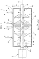
FIG. 1 is a schematic view illustrating a configuration of a rotary machine according to an embodiment of the present disclosure. -
FIG. 2 is a schematic view illustrating a configuration of a rotary machine according to a first modification example of the present disclosure. -
FIG. 3 is a schematic view illustrating a configuration of a rotary machine according to a second modification example of the present disclosure. - Hereinafter, an embodiment for a rotary machine according to the present disclosure will be described with reference to the attached drawings. However, the present disclosure is not limited to the embodiment only.
- Hereinafter, the rotary machine according to the embodiment of the present disclosure will be described with reference to
FIG. 1 . As illustrated inFIG. 1 , a rotary machine 1 is a so-called compander including acompression section 5 that functions as a compressor compressing a gas G and anexpansion section 6 that functions as an expander expanding the gas G. The rotary machine 1 mainly includes arotary shaft 2, acasing 3, a pair ofradial bearings compression section 5, theexpansion section 6, and a thrust bearing 9. - The
casing 3 forms the outer shell of the rotary machine 1. Thecasing 3 is formed in a tubular shape extending in an axial direction Da in which an axis O of therotary shaft 2 extends. Thecasing 3 covers part of therotary shaft 2, the pair ofradial bearings compression section 5, and theexpansion section 6. Thecasing 3 has a compressionsection suction port 33, a compressionsection discharge port 34, an expansionsection suction port 35, and an expansionsection discharge port 36. - The compression
section suction port 33 is an inlet nozzle for introducing the gas (fluid) G from a gas supply source (not illustrated) outside thecasing 3 into thecompression section 5 inside thecasing 3. The gas G having the lowest pressure in thecompression section 5 passes through the compressionsection suction port 33. The compressionsection discharge port 34 is an outlet nozzle for exhausting the gas G compressed by thecompression section 5 to the outside of thecasing 3. The gas G, which is compressed by thecompression section 5 and has the highest pressure in thecompression section 5, passes through the compressionsection discharge port 34. The expansionsection suction port 35 is an inlet nozzle for introducing the gas G into theexpansion section 6. The gas G having the highest pressure in theexpansion section 6 passes through the expansionsection suction port 35. The expansionsection discharge port 36 is an outlet nozzle for exhausting the gas G expanded by theexpansion section 6 to the outside of thecasing 3. The gas G, which is expanded by theexpansion section 6 and has the lowest pressure in theexpansion section 6, passes through the expansionsection discharge port 36. - In the present embodiment, the compression
section suction port 33, the compressionsection discharge port 34, the expansionsection suction port 35, and the expansionsection discharge port 36 are disposed side by side in this order in the axial direction Da from afirst end portion 2a of therotary shaft 2 toward asecond end portion 2b of therotary shaft 2. That is, among the compressionsection suction port 33, the compressionsection discharge port 34, the expansionsection suction port 35, and the expansionsection discharge port 36, the compressionsection suction port 33 is disposed at a position closest to thefirst end portion 2a of therotary shaft 2 in the axial direction Da. Among the compressionsection suction port 33, the compressionsection discharge port 34, the expansionsection suction port 35, and the expansionsection discharge port 36, the expansionsection discharge port 36 is disposed at a position closest to thesecond end portion 2b of therotary shaft 2 in the axial direction Da. In addition, among the compressionsection suction port 33, the compressionsection discharge port 34, the expansionsection suction port 35, and the expansionsection discharge port 36, the compressionsection discharge port 34 and the expansionsection suction port 35 are disposed at positions closest to each other in the axial direction Da. - The pair of
radial bearings casing 3. The pair ofradial bearings rotary shaft 2 to be rotatable about the axis O. The pair ofradial bearings casing 3. In the embodiment of the present disclosure, the radial bearing (first radial bearing) 4A is disposed on a first side Da1 in the axial direction Da in thecasing 3. The radial bearing (second radial bearing) 4B is disposed on a second side Da2 in the axial direction Da in thecasing 3. Herein, the first side Da1 in the axial direction Da is a side in the axial direction Da, on which thefirst end portion 2a of the rotary shaft is disposed with respect to thesecond end portion 2b of the rotary shaft. In addition, the second side Da2 in the axial direction Da is a side in the axial direction Da, on which thesecond end portion 2b of therotary shaft 2 is disposed with respect to thefirst end portion 2a of therotary shaft 2. Therefore, the radial bearing 4A is disposed at a position close to thefirst end portion 2a of therotary shaft 2. The radial bearing 4B is disposed at a position close to thesecond end portion 2b of therotary shaft 2. - The thrust bearing 9 supports the rotary shaft in the axial direction Da. The thrust bearing 9 is disposed at a position close to the
first end portion 2a or thesecond end portion 2b of the rotary shaft in the axial direction Da compared to thecompression section 5 and theexpansion section 6. The thrust bearing 9 of the present embodiment is disposed at a position close to the radial bearing 4A. Specifically, the thrust bearing 9 is disposed between thefirst end portion 2a and the radial bearing 4A in the axial direction Da. - The
rotary shaft 2 has a columnar shape centered on the axis O and extends in the axial direction Da. Therotary shaft 2 is capable of rotating about the axis O. Therotary shaft 2 is supported by the pair ofradial bearings casing 3. - The
compression section 5 compresses the gas G introduced from the outside of thecasing 3. Thecompression section 5 is disposed between the pair ofradial bearings casing 3. Between the pair ofradial bearings compression section 5 is disposed at a position near thefirst end portion 2a of therotary shaft 2. - The
compression section 5 includes one ormore compression impellers 51 that compress the gas G flowed inside. In the embodiment of the present disclosure, thecompression section 5 includes twocompression impellers 51. Thecompression section 5 may include three ormore compression impellers 51. The plurality ofcompression impellers 51 are disposed at an interval in the axial direction Da. Thecompression impellers 51 are fixed to therotary shaft 2, and rotate integrally with therotary shaft 2 about the axis O. Each of thecompression impellers 51 is, for example, a so-called closed impeller including a disk portion (not illustrated), a blade portion (not illustrated), and a cover portion (not illustrated). By rotating integrally with therotary shaft 2 about the axis O, each of thecompression impellers 51 transfers and compresses the gas G, which has flowed from the first side Da1 in the axial direction Da, while changing a flowing direction thereof to an outer side Dro in a radial direction Dr. - Such a
compression section 5 compresses the gas G, which is sucked from the outside of thecasing 3 through the compressionsection suction port 33, with each of thecompression impellers 51. The gas G, which has become high-temperature and high-pressure by passing through the plurality ofcompression impellers 51 and being compressed at a plurality of stages in thecompression section 5, is discharged from the compressionsection discharge port 34 to the outside of thecasing 3. - The
expansion section 6 expands the gas G introduced from the outside of thecasing 3. Theexpansion section 6 is disposed between the pair ofradial bearings casing 3. Theexpansion section 6 is disposed on the second side Da2 in the axial direction Da with respect to thecompression section 5. Between the pair ofradial bearings expansion section 6 is disposed at a position near thesecond end portion 2b of therotary shaft 2. A space between thecompression section 5 and theexpansion section 6 is split up by thecasing 3 so as to be separated from each other. - The
expansion section 6 includes one ormore expansion impellers 61 that expand the gas G flowed inside. In the embodiment of the present disclosure, theexpansion section 6 includes twoexpansion impellers 61. Theexpansion section 6 may include three ormore expansion impellers 61. In addition, the number ofexpansion impellers 61 is not limited to being the same as the number ofcompression impellers 51. The plurality ofexpansion impellers 61 are disposed on the second side Da2 in the axial direction Da with respect to the plurality ofcompression impellers 51. The plurality ofexpansion impellers 61 are disposed at an interval in the axial direction Da. Theexpansion impellers 61 are fixed to therotary shaft 2. Theexpansion impellers 61 rotate integrally with therotary shaft 2 about the axis O. Theexpansion impellers 61 each are, for example, a closed impeller like thecompression impeller 51. - The
expansion impeller 61 transfers and expands the gas G flowing from the outer side Dro in the radial direction Dr while changing a flowing direction thereof to the second side Da2 in the axial direction Da. At this time, as the gas G expands, a rotation force about the axis O is applied to each of theexpansion impellers 61. - Such an
expansion section 6 expands the gas G, which is sucked from the outside of thecasing 3 through the expansionsection suction port 35, with each of theexpansion impellers 61. The gas G, which has become low-temperature and low-pressure by passing through the plurality ofexpansion impellers 61 and being expanded at a plurality of stages in theexpansion section 6, is discharged from the expansionsection discharge port 36 to the outside of thecasing 3. - In the embodiment of the present disclosure, the rotary machine 1 is connected to a
drive machine 8. Thedrive machine 8 rotationally drives therotary shaft 2 about the axis O. Thedrive machine 8 is, for example, a motor. Thedrive machine 8 is connected to thefirst end portion 2a of therotary shaft 2 in the axial direction Da. That is, thedrive machine 8 is disposed next to the rotary machine 1 so as to be positioned on an opposite side of theexpansion section 6 with thecompression section 5 interposed therebetween. Anoutput shaft 81a of thedrive machine 8 is connected to therotary shaft 2 outside thecasing 3. When thedrive machine 8 is operated to rotate theoutput shaft 81a about the axis O, therotary shaft 2 is rotationally driven about the axis O integrally with theoutput shaft 81a. - In the rotary machine 1 having the configuration, the
compression section 5 that compresses the gas G introduced from the outside of thecasing 3 and theexpansion section 6 that expands the gas G introduced from the outside of thecasing 3 are included in onecasing 3. In such a rotary machine 1, thecompression impeller 51 and theexpansion impeller 61 are disposed only between the pair ofradial bearings radial bearings rotary shaft 2 can be improved. - Further, in the
casing 3, the compressionsection suction port 33, the compressionsection discharge port 34, the expansionsection suction port 35, and the expansionsection discharge port 36 are disposed side by side in this order from the first side Da1 in the axial direction Da. Theexpansion impeller 61 is disposed side by side with thecompression section 5 between the pair ofradial bearings casing 3. Specifically, thecompression impeller 51 is disposed at a position near the first side Da1 in the axial direction Da in thecasing 3. In addition, theexpansion impeller 61 is disposed at a position near the second side Da2 in the axial direction Da in thecasing 3. That is, thecompression impeller 51 and theexpansion impeller 61 are disposed to face opposite directions from each other in the axial direction Da. In such a configuration, a thrust force Fs1 in the axial direction Da, which acts on thecompression impeller 51 by compressing the gas G, is generated to face the first side Da1 in the axial direction Da. In addition, a thrust force Fs2 in the axial direction Da, which acts on theexpansion impeller 61 by expanding the gas G, is generated to face the second side Da2 in the axial direction Da. As a result, the thrust force Fs1 acting on thecompression impeller 51 and the thrust force Fs2 acting on theexpansion impeller 61 cancel each other out. Accordingly, the thrust forces acting on therotary shaft 2 can be suppressed. - A thrust force that remains as the thrust force Fs1 in the axial direction Da, which acts on the
compression impeller 51 by compressing the gas G, and the thrust force Fs2 in the axial direction Da, which acts on theexpansion impeller 61 by expanding the gas G, have not completely canceled each other out is suppressed by thethrust bearing 9 provided in the vicinity of theradial bearing - In addition, in the
expansion section 6, the plurality ofexpansion impellers 61 are disposed at an interval in the axial direction Da. That is, theexpansion section 6 configures a multi-stage expander. As the gas G is gradually expanded by the plurality ofexpansion impellers 61, the generation of a loss is suppressed when expanding the gas G, and the gas G can be efficiently expanded. In addition, in theexpansion section 6, therotary shaft 2 rotates by energy generated when the gas G expands. At this time, as the gas G is gradually expanded, the energy can be efficiently collected. - In the
compression section 5, the plurality ofcompression impellers 51 are disposed at an interval in the axial direction Da. That is, thecompression section 5 configures a multi-stage compressor. The plurality ofcompression impellers 51 can respond to a high discharge pressure. - The
drive machine 8 is connected to thefirst end portion 2a of therotary shaft 2. Accordingly, therotary shaft 2 can be rotated by energy generated when theexpansion section 6 expands the gas G, and therotary shaft 2 can be assisted in generating a rotational driving force as thedrive machine 8 rotationally drives therotary shaft 2 about the axis O. In addition, thedrive machine 8 is disposed on the opposite side of theexpansion section 6 in the axial direction Da with thecompression section 5 interposed therebetween. Therefore, therotary shaft 2 is rotationally driven about the axis O with respect to thecompression section 5 by thedrive machine 8 on the first side Da1 in the axial direction Da and theexpansion section 6 on the second side Da2 in the axial direction Da. Accordingly, it is possible to suppress an increase in the magnitude of stress on therotary shaft 2 in a torsional direction about the axis O. - While preferred embodiments of the invention have been described and illustrated above, it should be understood that these are exemplary of the invention and are not to be considered as limiting. Additions, omissions, substitutions, and other modifications can be made without departing from the spirit or scope of the present invention. Accordingly, the invention is not to be considered as being limited by the foregoing description, and is only limited by the scope of the appended claims.
- For example, as a first modification example, as illustrated in
FIG. 2 , the rotary machine 1 may further include afeeding unit 7 that connects the compressionsection discharge port 34 and the expansionsection suction port 35 to each other. - The
feeding unit 7 is disposed between thecompression section 5 and theexpansion section 6. Thefeeding unit 7 feeds the gas G compressed by thecompression section 5 in thecasing 3 to theexpansion section 6. Thefeeding unit 7 includes afeeding line 71 and aheat exchanger 72. - The
feeding line 71 is a pipe that connects the compressionsection discharge port 34 and the expansionsection suction port 35 to each other outside thecasing 3. The gas G compressed by thecompression section 5 in thecasing 3 flows into thefeeding line 71 from the compressionsection discharge port 34. The gas G flowed into thefeeding line 71 is supplied from the expansionsection suction port 35 to theexpansion section 6 in thecasing 3 via theheat exchanger 72. - The
heat exchanger 72 is disposed in thefeeding line 71. Theheat exchanger 72 is capable of collecting the heat of the gas G flowing in thefeeding line 71. Specifically, theheat exchanger 72 exchanges heat between the gas G flowing in thefeeding line 71 and a heat medium (not illustrated). Accordingly, the temperature of the gas G, which has passed through theheat exchanger 72, declines, and the temperature of the heat medium rises. - By disposing such a
feeding unit 7, the heat of the gas G, which is compressed by thecompression section 5 and is yet to be fed to theexpansion section 6, can be efficiently used. Specifically, theheat exchanger 72 that takes away the heat of the gas G is disposed in thefeeding unit 7 that feeds the gas G compressed by thecompression section 5 to theexpansion section 6. Accordingly, as theheat exchanger 72 takes away the heat of the gas G, which is compressed by thecompression section 5 and is high-temperature, the heat of the gas G can be effectively used. In addition, as theheat exchanger 72 collects the heat of the gas G, the temperature of the gas G declines. As theexpansion section 6 expands the gas G of which a temperature has declined, the gas G has a lower temperature and a lower pressure. Therefore, the rotary machine 1 can be effectively used as, for example, a cryocooler. - In the first modification example, the purpose of the heat medium heated by exchanging heat with the gas G by the
heat exchanger 72 is not limited at all. - In addition, although an example, in which the rotary machine 1 is used as a cryocooler by expanding the gas G, of which heat is taken away by the
heat exchanger 72, with theexpansion section 6 and making the temperature of the gas G a cryogenic temperature, has been given, the rotary machine 1 may be used for other purposes. - In addition, a structure of supplying the gas G into the
casing 3 or exhausting the gas G to the outside is not limited only to the compressionsection suction port 33, the compressionsection discharge port 34, the expansionsection suction port 35, and the expansionsection discharge port 36. For example, the rotary machine 1 may have another suction port or discharge port between the compressionsection suction port 33 and the compressionsection discharge port 34 in the axial direction Da. In addition, the rotary machine 1 may have another suction port or discharge port between the expansionsection suction port 35 and the expansionsection discharge port 36 in the axial direction Da. - Specifically, as a second modification example, as illustrated in
FIG. 3 , thecasing 3 has a second compressionsection suction port 41 and a second compressionsection discharge port 42, between the compressionsection suction port 33 and the compressionsection discharge port 34. The second compressionsection suction port 41 is on a downstream side of the compressionsection suction port 33, and the gas G is introduced into the middle of thecompression section 5 inside thecasing 3. On the downstream side of the second compressionsection suction port 41 and on the upstream side of the compressionsection discharge port 34, the second compressionsection discharge port 42 causes the compressed gas G to be exhausted from the middle of thecompression section 5 to the outside of thecasing 3. - Further, the
casing 3 has a second expansionsection discharge port 45, a second expansionsection suction port 46, and a third expansionsection discharge port 47, between the expansionsection suction port 35 and the expansionsection discharge port 36. On the downstream side of the expansionsection suction port 35, the second expansionsection discharge port 45 causes the expanded gas G to be exhausted from the middle of theexpansion section 6 to the outside of thecasing 3. On the downstream side of the second expansionsection discharge port 45 and on the upstream side of the third expansionsection discharge port 47, the second expansionsection suction port 46 causes the gas G to be introduced into the middle of theexpansion section 6 inside thecasing 3. On the downstream side of the second expansionsection suction port 46 and on the upstream side of the expansionsection discharge port 36, the third expansionsection discharge port 47 causes the expanded gas G to be exhausted from the middle of theexpansion section 6 to the outside of thecasing 3. - In addition, although the closed impeller is given as an example of the
compression impeller 51 or theexpansion impeller 61 in the present embodiment, the invention is not limited to such a configuration. For example, thecompression impeller 51 and theexpansion impeller 61 may be open impellers without a cover. In addition, in a case where the plurality ofcompression impellers 51 and the plurality ofexpansion impellers 61 are disposed, closed impellers and open impellers may be mixed. - In addition, a position where the
thrust bearing 9 is disposed is not limited to the position in the present embodiment. For example, thethrust bearing 9 may be disposed between theradial bearing 4A and thecompression section 5 in the axial direction Da. In addition, thethrust bearing 9 may be disposed at a position close to theradial bearing 4B. In this case, thethrust bearing 9 may be disposed between theradial bearing 4B and theexpansion section 6, or between theradial bearing 4B and thesecond end portion 2b. - In addition, although a schematic configuration of each part of the rotary machine 1 has been described in the embodiment, a specific configuration thereof is not limited at all.
- The rotary machine 1 described in the embodiment is identified as follows, for example.
- (1) The rotary machine 1 according to a first aspect includes the
rotary shaft 2 that is configured to rotate about the axis O, thecasing 3 that covers therotary shaft 2, the pair ofradial bearings casing 3 and supports therotary shaft 2 to be rotatable about the axis O, thecompression section 5 that is disposed between the pair ofradial bearings casing 3 and is configured to compress a fluid, which has been introduced from the outside of thecasing 3, theexpansion section 6 that is disposed side by side thecompression section 5, between the pair ofradial bearings casing 3 and is configured to expand the fluid introduced from the outside of thecasing 3, and thethrust bearing 9 that is disposed at a position close to thefirst end portion 2a or thesecond end portion 2b of therotary shaft 2 in the axial direction Da with respect to thecompression section 5 and theexpansion section 6 and supports therotary shaft 2 in the axial direction Da. Thecompression section 5 includes the at least onecompression impeller 51 that is fixed to therotary shaft 2 and is configured to rotate integrally therewith to compress the fluid which has flowed inside. Theexpansion section 6 includes the at least oneexpansion impeller 61 that is fixed to therotary shaft 2 and is configured to rotate integrally therewith to expand the fluid which has flowed inside. Thecasing 3 has the compressionsection suction port 33 that is configured to cause the fluid, of which a pressure is lowest in thecompression section 5 to be introduced into thecompression section 5, the compressionsection discharge port 34 that is configured to cause the fluid, which is compressed by thecompression section 5 and has the highest pressure in thecompression section 5, to be exhausted to the outside of thecasing 3, the expansionsection suction port 35 that is configured to cause the fluid, of which a pressure is highest in theexpansion section 6, to be introduced into theexpansion section 6, and the expansionsection discharge port 36 that is configured to cause the fluid, which is expanded by theexpansion section 6 and has the lowest pressure in theexpansion section 6, to be exhausted to the outside of thecasing 3. Among the compressionsection suction port 33, the compressionsection discharge port 34, the expansionsection suction port 35, and the expansionsection discharge port 36, the compressionsection suction port 33 is disposed at a position closest to thefirst end portion 2a in the axial direction Da, and the expansionsection discharge port 36 is disposed at a position closest to thesecond end portion 2b in the axial direction Da.
In such a rotary machine 1, thecompression impeller 51 and theexpansion impeller 61 are disposed only between the pair ofradial bearings radial bearings rotary shaft 2 can be improved. Further, in thecasing 3, the compressionsection suction port 33, the compressionsection discharge port 34, the expansionsection suction port 35, and the expansionsection discharge port 36 are disposed side by side in this order from thefirst end portion 2a in the axial direction Da. Theexpansion impeller 61 is disposed side by side with thecompression section 5 between the pair ofradial bearings casing 3. That is, thecompression impeller 51 and theexpansion impeller 61 are disposed to face opposite directions from each other in the axial direction Da. In such a configuration, the thrust force Fs1 in the axial direction Da, which acts on thecompression impeller 51 by compressing the fluid, is generated to face thefirst end portion 2a in the axial direction Da. In addition, the thrust force Fs2 in the axial direction Da, which acts on theexpansion impeller 61 by expanding the fluid, is generated to face thesecond end portion 2b in the axial direction Da. As a result, the thrust force Fs1 acting on thecompression impeller 51 and the thrust force Fs2 acting on theexpansion impeller 61 cancel each other out. Accordingly, the thrust forces acting on therotary shaft 2 can be suppressed. - (2) The rotary machine 1 according to a second aspect is the rotary machine 1 of (1), in which the at least one
expansion impeller 61 comprises includes the plurality ofexpansion impellers 61 disposed at an interval in the axial direction Da.
As the fluid is gradually expanded by the plurality ofexpansion impellers 61, the generation of a loss is suppressed when expanding the fluid, and the fluid can be efficiently expanded. In addition, in theexpansion section 6, therotary shaft 2 rotates by energy generated when the fluid expands. At this time, as the fluid is gradually expanded, the energy can be efficiently collected. - (3) The rotary machine 1 according to a third aspect is the rotary machine 1 of (1) or (2), in which the at least one
compression impeller 51 comprises includes the plurality ofcompression impellers 51 disposed at an interval in the axial direction Da.
The plurality ofcompression impellers 51 can respond to a high discharge pressure. - (4) The rotary machine 1 according to a fourth aspect is the rotary machine 1 of any one of (1) to (3), and further includes the
feeding unit 7 that connects the compressionsection discharge port 34 and the expansionsection suction port 35 to each other. Thefeeding unit 7 has theheat exchanger 72 that is configured to collect the heat of the fluid.
Accordingly, as theheat exchanger 72 takes away the heat of the fluid, which is compressed by thecompression section 5 and is high-temperature, the heat of the fluid can be effectively used. In addition, as theheat exchanger 72 collects the heat of the fluid, the temperature of the fluid declines. As theexpansion section 6 expands the fluid of which a temperature has declined, the fluid has a lower temperature and a lower pressure. Accordingly, the rotary machine 1 can be effectively used as, for example, a cryocooler. - (5) The rotary machine 1 according to a fifth aspect is the rotary machine 1 according to any one of (1) to (4), in which in the
casing 3, the compressionsection suction port 33, the compressionsection discharge port 34, the expansionsection suction port 35, and the expansionsection discharge port 36 are disposed side by side in this order in the axial direction Da from thefirst end portion 2a toward thesecond end portion 2b. - With the rotary machine of the present disclosure, it is possible to improve the rotor dynamics of the rotary shaft.
-
- 1
- rotary machine
- 2
- rotary shaft
- 2a
- first end portion
- 2b
- second end portion
- 3
- casing
- 4A, 4B
- radial bearing
- 5
- compression section
- 6
- expansion section
- 7
- feeding unit
- 8
- drive machine
- 9
- thrust bearing
- 33
- compression section suction port
- 34
- compression section discharge port
- 35
- expansion section suction port
- 36
- expansion section discharge port
- 51
- compression impeller
- 61
- expansion impeller
- 71
- feeding line
- 72
- heat exchanger
- 81a
- output shaft
- Da
- axial direction
- Da1
- first side
- Da2
- second side
- Dr
- radial direction
- Dro
- outer side
- Fs1, Fs2
- thrust force
- G
- gas (fluid)
- O
- axis
Claims (5)
- A rotary machine comprising:a rotary shaft that is configured to rotate about an axis;a casing that covers the rotary shaft;a pair of radial bearings that is fixed to the casing and supports the rotary shaft to be rotatable about the axis;a compression section that is disposed between the pair of radial bearings in an axial direction, in which the axis extends, in the casing and is configured to compress a fluid introduced from an outside of the casing;an expansion section that is disposed side by side with the compression section, between the pair of radial bearings in the axial direction, in the casing and is configured to expand the fluid introduced from the outside of the casing; anda thrust bearing that is disposed at a position close to a first end portion or a second end portion of the rotary shaft in the axial direction with respect to the compression section and the expansion section and supports the rotary shaft in the axial direction,wherein the compression section includes at least one compression impeller that is fixed to the rotary shaft and is configured to rotate integrally with the rotary shaft to compress the fluid which has flowed inside,the expansion section includes at least one expansion impeller that is fixed to the rotary shaft and is configured to rotate integrally with the rotary shaft to expand the fluid which has flowed inside,the casing hasa compression section suction port that is configured to cause the fluid, of which a pressure is lowest in the compression section, to be introduced into the compression section,a compression section discharge port that is configured to cause the fluid, which is compressed by the compression section and has a highest pressure in the compression section, to be exhausted to an outside of the casing,an expansion section suction port that is configured to cause the fluid, of which a pressure is highest in the expansion section, to be introduced into the expansion section, andan expansion section discharge port that is configured to cause the fluid, which is expanded by the expansion section and has a lowest pressure in the expansion section, to be exhausted to the outside of the casing, andamong the compression section suction port, the compression section discharge port, the expansion section suction port, and the expansion section discharge port, the compression section suction port is disposed at a position closest to the first end portion in the axial direction, and the expansion section discharge port is disposed at a position closest to the second end portion in the axial direction.
- The rotary machine according to claim 1,
wherein the at least one expansion impeller comprises a plurality of the expansion impellers that are disposed at an interval in the axial direction. - The rotary machine according to claim 1 or 2,
wherein the at least one compression impeller comprises a plurality of the compression impellers that are disposed at an interval in the axial direction. - The rotary machine according to any one of claims 1 to 3, further comprising:a feeding unit that connects the compression section discharge port and the expansion section suction port to each other,wherein the feeding unit has a heat exchanger that is configured to collect heat of the fluid.
- The rotary machine according to any one of claims 1 to 4,
wherein in the casing, the compression section suction port, the compression section discharge port, the expansion section suction port, and the expansion section discharge port are disposed side by side in this order in the axial direction from the first end portion toward the second end portion.
Applications Claiming Priority (1)
| Application Number | Priority Date | Filing Date | Title |
|---|---|---|---|
| JP2020016565A JP7493346B2 (en) | 2020-02-03 | 2020-02-03 | Rotating Machinery |
Publications (2)
| Publication Number | Publication Date |
|---|---|
| EP3859161A1 true EP3859161A1 (en) | 2021-08-04 |
| EP3859161B1 EP3859161B1 (en) | 2025-10-08 |
Family
ID=74285209
Family Applications (1)
| Application Number | Title | Priority Date | Filing Date |
|---|---|---|---|
| EP21153407.8A Active EP3859161B1 (en) | 2020-02-03 | 2021-01-26 | Rotary machine |
Country Status (4)
| Country | Link |
|---|---|
| US (1) | US11560903B2 (en) |
| EP (1) | EP3859161B1 (en) |
| JP (1) | JP7493346B2 (en) |
| CN (1) | CN113202565A (en) |
Families Citing this family (3)
| Publication number | Priority date | Publication date | Assignee | Title |
|---|---|---|---|---|
| CN113898597B (en) * | 2021-09-24 | 2024-11-29 | 李媛 | Compression decompression all-in-one |
| CN119957520A (en) * | 2025-01-24 | 2025-05-09 | 中国科学院理化技术研究所 | A high pressure ratio compression expansion machine |
| CN120626284B (en) * | 2025-07-03 | 2025-12-12 | 北京航天试验技术研究所 | A low-temperature turbine expander |
Citations (3)
| Publication number | Priority date | Publication date | Assignee | Title |
|---|---|---|---|---|
| US20130091869A1 (en) | 2010-01-15 | 2013-04-18 | Samsung Techwin Co., Ltd. | Integral compressor-expander |
| CN110080989A (en) * | 2019-05-20 | 2019-08-02 | 大连深蓝泵业有限公司 | Coaxial-type is arranged symmetrically multistage hydraulic turbine and directly drives pump and its application method |
| US20190293117A1 (en) * | 2018-03-23 | 2019-09-26 | General Electric Company | Closed Cycle Heat Engine |
Family Cites Families (23)
| Publication number | Priority date | Publication date | Assignee | Title |
|---|---|---|---|---|
| US3202341A (en) * | 1963-04-18 | 1965-08-24 | Fleur Corp | Turbomachines assembly |
| JPS6147435U (en) * | 1984-09-03 | 1986-03-29 | 石川島播磨重工業株式会社 | Turbocharger bearing device |
| JPH0612118B2 (en) * | 1986-09-17 | 1994-02-16 | 株式会社神戸製鋼所 | Gas-lubricated bearing arrangement for two-stage single-shaft turbo compressor |
| US5626459A (en) * | 1992-10-13 | 1997-05-06 | Cosby; Thomas L. | Unitary turbine/compressor engine |
| US5555745A (en) * | 1995-04-05 | 1996-09-17 | Rotoflow Corporation | Refrigeration system |
| US7823398B2 (en) * | 2006-05-07 | 2010-11-02 | John Stewart Glen | Compressor/expander of the rotating vane type |
| EP2057353A1 (en) * | 2006-08-25 | 2009-05-13 | Commonwealth Scientific and Industrial Research Organisation | A heat engine system |
| JP4897018B2 (en) | 2009-08-19 | 2012-03-14 | 三菱重工コンプレッサ株式会社 | Mechanical unit placement system |
| JP4927129B2 (en) | 2009-08-19 | 2012-05-09 | 三菱重工コンプレッサ株式会社 | Radial gas expander |
| US20110097225A1 (en) | 2009-10-28 | 2011-04-28 | Freund Sebastian W | Air compression and expansion system with single shaft compressor and turbine arrangement |
| IT1399881B1 (en) | 2010-05-11 | 2013-05-09 | Nuova Pignone S R L | CONFIGURATION OF BALANCING DRUM FOR COMPRESSOR ROTORS |
| US9551349B2 (en) | 2011-04-08 | 2017-01-24 | Dresser-Rand Company | Circulating dielectric oil cooling system for canned bearings and canned electronics |
| JP5959816B2 (en) | 2011-09-01 | 2016-08-02 | 三菱重工コンプレッサ株式会社 | Radial gas expander |
| JP2013244751A (en) | 2012-05-23 | 2013-12-09 | Shimadzu Corp | Air-conditioning system |
| JP6037916B2 (en) * | 2013-03-29 | 2016-12-07 | 三菱日立パワーシステムズ株式会社 | Rotating shaft support structure and rotating machine |
| JP6736469B2 (en) | 2014-03-11 | 2020-08-05 | ヌオーヴォ ピニォーネ ソチエタ レスポンサビリタ リミタータNuovo Pignone S.R.L. | Turbo machine assembly |
| DE102014206162A1 (en) * | 2014-04-01 | 2015-10-01 | Bosch Mahle Turbo Systems Gmbh & Co. Kg | turbocharger |
| US20150314666A1 (en) | 2014-05-02 | 2015-11-05 | Hamilton Sundstrand Corporation | Aircraft environmental conditioning system and method |
| US20150314878A1 (en) | 2014-05-02 | 2015-11-05 | Hamilton Sundstrand Corporation | Aircraft environmental conditioning system and method |
| US20160297694A1 (en) * | 2015-04-07 | 2016-10-13 | General Electric Company | Hybrid vapor compression membrane distillation drive assemblyand method of use |
| US10514065B2 (en) | 2015-12-14 | 2019-12-24 | Hamilton Sundstrand Corporation | Bearing thermal management system and method |
| US9784126B2 (en) | 2015-12-14 | 2017-10-10 | Hamilton Sundstrand Corporation | Variable-sized cooling air flow path |
| CN109779706B (en) * | 2019-03-13 | 2023-10-27 | 中国科学院上海高等研究院 | A fully closed Brayton cycle thermal power conversion device |
-
2020
- 2020-02-03 JP JP2020016565A patent/JP7493346B2/en active Active
-
2021
- 2021-01-19 US US17/152,044 patent/US11560903B2/en active Active
- 2021-01-26 EP EP21153407.8A patent/EP3859161B1/en active Active
- 2021-02-01 CN CN202110139263.0A patent/CN113202565A/en active Pending
Patent Citations (3)
| Publication number | Priority date | Publication date | Assignee | Title |
|---|---|---|---|---|
| US20130091869A1 (en) | 2010-01-15 | 2013-04-18 | Samsung Techwin Co., Ltd. | Integral compressor-expander |
| US20190293117A1 (en) * | 2018-03-23 | 2019-09-26 | General Electric Company | Closed Cycle Heat Engine |
| CN110080989A (en) * | 2019-05-20 | 2019-08-02 | 大连深蓝泵业有限公司 | Coaxial-type is arranged symmetrically multistage hydraulic turbine and directly drives pump and its application method |
Also Published As
| Publication number | Publication date |
|---|---|
| CN113202565A (en) | 2021-08-03 |
| JP7493346B2 (en) | 2024-05-31 |
| JP2021124038A (en) | 2021-08-30 |
| US20210239131A1 (en) | 2021-08-05 |
| EP3859161B1 (en) | 2025-10-08 |
| US11560903B2 (en) | 2023-01-24 |
Similar Documents
| Publication | Publication Date | Title |
|---|---|---|
| EP3859161B1 (en) | Rotary machine | |
| US8882457B2 (en) | Multistage radial turbocompressor | |
| CN102257276B (en) | Scroll fluid machine | |
| CN100554700C (en) | Turbocompressor | |
| US3657898A (en) | Method and apparatus for producing refrigeration | |
| US11788546B2 (en) | Ammonia plant synthesis gas compressor train | |
| EP2386763B1 (en) | Multistage compressor with balancing pistons | |
| EP2861870B1 (en) | Centrifugal compressor impeller cooling | |
| EP3935270B1 (en) | Multistage compressor-expander turbomachine configuration | |
| CN1092746C (en) | Steam turbine | |
| CN112983853A (en) | High-speed turbine structure applied to large flow and large expansion ratio | |
| CN112253491A (en) | Multistage centrifugal supercritical carbon dioxide compressor | |
| US11499445B2 (en) | CO2 turbine power generation system | |
| CN106536936B (en) | Liquid Ring Compressor | |
| JP6158008B2 (en) | Rotating machine | |
| CN201896763U (en) | Compressor | |
| US11898566B2 (en) | Motor-driven compressor having a compression section mounted on a free end of a cantilvered shaft | |
| CN102859202B (en) | Axial flow compressor | |
| CN114829746A (en) | Rotary machine and refrigeration device using same | |
| KR20220159795A (en) | Turbo Compressor | |
| KR20180097390A (en) | Turbo compressor | |
| WO1981000139A1 (en) | Multi-stage centrifugal compressor | |
| JPWO2020144854A1 (en) | Rotating machine | |
| WO2026027551A1 (en) | Multistage turboexpander | |
| KR20260041116A (en) | Integrated geared turbomachine system having at least two impellers with different rotational speeds |
Legal Events
| Date | Code | Title | Description |
|---|---|---|---|
| PUAI | Public reference made under article 153(3) epc to a published international application that has entered the european phase |
Free format text: ORIGINAL CODE: 0009012 |
|
| STAA | Information on the status of an ep patent application or granted ep patent |
Free format text: STATUS: THE APPLICATION HAS BEEN PUBLISHED |
|
| AK | Designated contracting states |
Kind code of ref document: A1 Designated state(s): AL AT BE BG CH CY CZ DE DK EE ES FI FR GB GR HR HU IE IS IT LI LT LU LV MC MK MT NL NO PL PT RO RS SE SI SK SM TR |
|
| STAA | Information on the status of an ep patent application or granted ep patent |
Free format text: STATUS: REQUEST FOR EXAMINATION WAS MADE |
|
| 17P | Request for examination filed |
Effective date: 20220204 |
|
| RBV | Designated contracting states (corrected) |
Designated state(s): AL AT BE BG CH CY CZ DE DK EE ES FI FR GB GR HR HU IE IS IT LI LT LU LV MC MK MT NL NO PL PT RO RS SE SI SK SM TR |
|
| STAA | Information on the status of an ep patent application or granted ep patent |
Free format text: STATUS: EXAMINATION IS IN PROGRESS |
|
| 17Q | First examination report despatched |
Effective date: 20230321 |
|
| GRAP | Despatch of communication of intention to grant a patent |
Free format text: ORIGINAL CODE: EPIDOSNIGR1 |
|
| STAA | Information on the status of an ep patent application or granted ep patent |
Free format text: STATUS: GRANT OF PATENT IS INTENDED |
|
| INTG | Intention to grant announced |
Effective date: 20250507 |
|
| RAP3 | Party data changed (applicant data changed or rights of an application transferred) |
Owner name: MITSUBISHI HEAVY INDUSTRIES COMPRESSOR CORPORATION |
|
| GRAS | Grant fee paid |
Free format text: ORIGINAL CODE: EPIDOSNIGR3 |
|
| GRAA | (expected) grant |
Free format text: ORIGINAL CODE: 0009210 |
|
| STAA | Information on the status of an ep patent application or granted ep patent |
Free format text: STATUS: THE PATENT HAS BEEN GRANTED |
|
| AK | Designated contracting states |
Kind code of ref document: B1 Designated state(s): AL AT BE BG CH CY CZ DE DK EE ES FI FR GB GR HR HU IE IS IT LI LT LU LV MC MK MT NL NO PL PT RO RS SE SI SK SM TR |
|
| REG | Reference to a national code |
Ref country code: GB Ref legal event code: FG4D Ref country code: CH Ref legal event code: F10 Free format text: ST27 STATUS EVENT CODE: U-0-0-F10-F00 (AS PROVIDED BY THE NATIONAL OFFICE) Effective date: 20251008 |
|
| REG | Reference to a national code |
Ref country code: DE Ref legal event code: R096 Ref document number: 602021039891 Country of ref document: DE |
|
| REG | Reference to a national code |
Ref country code: IE Ref legal event code: FG4D |
|
| REG | Reference to a national code |
Ref country code: NL Ref legal event code: MP Effective date: 20251008 |
|
| REG | Reference to a national code |
Ref country code: AT Ref legal event code: MK05 Ref document number: 1845002 Country of ref document: AT Kind code of ref document: T Effective date: 20251008 |
|
| PG25 | Lapsed in a contracting state [announced via postgrant information from national office to epo] |
Ref country code: NL Free format text: LAPSE BECAUSE OF FAILURE TO SUBMIT A TRANSLATION OF THE DESCRIPTION OR TO PAY THE FEE WITHIN THE PRESCRIBED TIME-LIMIT Effective date: 20251008 |
|
| PG25 | Lapsed in a contracting state [announced via postgrant information from national office to epo] |
Ref country code: ES Free format text: LAPSE BECAUSE OF FAILURE TO SUBMIT A TRANSLATION OF THE DESCRIPTION OR TO PAY THE FEE WITHIN THE PRESCRIBED TIME-LIMIT Effective date: 20251008 |
|
| REG | Reference to a national code |
Ref country code: LT Ref legal event code: MG9D |
|
| PG25 | Lapsed in a contracting state [announced via postgrant information from national office to epo] |
Ref country code: NO Free format text: LAPSE BECAUSE OF FAILURE TO SUBMIT A TRANSLATION OF THE DESCRIPTION OR TO PAY THE FEE WITHIN THE PRESCRIBED TIME-LIMIT Effective date: 20260108 |
|
| PGFP | Annual fee paid to national office [announced via postgrant information from national office to epo] |
Ref country code: DE Payment date: 20260127 Year of fee payment: 6 |
|
| PG25 | Lapsed in a contracting state [announced via postgrant information from national office to epo] |
Ref country code: AT Free format text: LAPSE BECAUSE OF FAILURE TO SUBMIT A TRANSLATION OF THE DESCRIPTION OR TO PAY THE FEE WITHIN THE PRESCRIBED TIME-LIMIT Effective date: 20251008 Ref country code: HR Free format text: LAPSE BECAUSE OF FAILURE TO SUBMIT A TRANSLATION OF THE DESCRIPTION OR TO PAY THE FEE WITHIN THE PRESCRIBED TIME-LIMIT Effective date: 20251008 Ref country code: FI Free format text: LAPSE BECAUSE OF FAILURE TO SUBMIT A TRANSLATION OF THE DESCRIPTION OR TO PAY THE FEE WITHIN THE PRESCRIBED TIME-LIMIT Effective date: 20251008 |
|
| PGFP | Annual fee paid to national office [announced via postgrant information from national office to epo] |
Ref country code: IT Payment date: 20260107 Year of fee payment: 6 |
|
| PG25 | Lapsed in a contracting state [announced via postgrant information from national office to epo] |
Ref country code: RS Free format text: LAPSE BECAUSE OF FAILURE TO SUBMIT A TRANSLATION OF THE DESCRIPTION OR TO PAY THE FEE WITHIN THE PRESCRIBED TIME-LIMIT Effective date: 20260108 |
|
| PG25 | Lapsed in a contracting state [announced via postgrant information from national office to epo] |
Ref country code: IS Free format text: LAPSE BECAUSE OF FAILURE TO SUBMIT A TRANSLATION OF THE DESCRIPTION OR TO PAY THE FEE WITHIN THE PRESCRIBED TIME-LIMIT Effective date: 20260208 |
|
| PG25 | Lapsed in a contracting state [announced via postgrant information from national office to epo] |
Ref country code: PT Free format text: LAPSE BECAUSE OF FAILURE TO SUBMIT A TRANSLATION OF THE DESCRIPTION OR TO PAY THE FEE WITHIN THE PRESCRIBED TIME-LIMIT Effective date: 20260209 |
|
| PG25 | Lapsed in a contracting state [announced via postgrant information from national office to epo] |
Ref country code: PL Free format text: LAPSE BECAUSE OF FAILURE TO SUBMIT A TRANSLATION OF THE DESCRIPTION OR TO PAY THE FEE WITHIN THE PRESCRIBED TIME-LIMIT Effective date: 20251008 |
|
| PG25 | Lapsed in a contracting state [announced via postgrant information from national office to epo] |
Ref country code: LV Free format text: LAPSE BECAUSE OF FAILURE TO SUBMIT A TRANSLATION OF THE DESCRIPTION OR TO PAY THE FEE WITHIN THE PRESCRIBED TIME-LIMIT Effective date: 20251008 |
|
| PG25 | Lapsed in a contracting state [announced via postgrant information from national office to epo] |
Ref country code: BG Free format text: LAPSE BECAUSE OF FAILURE TO SUBMIT A TRANSLATION OF THE DESCRIPTION OR TO PAY THE FEE WITHIN THE PRESCRIBED TIME-LIMIT Effective date: 20251008 |
|
| PG25 | Lapsed in a contracting state [announced via postgrant information from national office to epo] |
Ref country code: LT Free format text: LAPSE BECAUSE OF FAILURE TO SUBMIT A TRANSLATION OF THE DESCRIPTION OR TO PAY THE FEE WITHIN THE PRESCRIBED TIME-LIMIT Effective date: 20251008 |
|
| PG25 | Lapsed in a contracting state [announced via postgrant information from national office to epo] |
Ref country code: SM Free format text: LAPSE BECAUSE OF FAILURE TO SUBMIT A TRANSLATION OF THE DESCRIPTION OR TO PAY THE FEE WITHIN THE PRESCRIBED TIME-LIMIT Effective date: 20251008 |
|
| PG25 | Lapsed in a contracting state [announced via postgrant information from national office to epo] |
Ref country code: DK Free format text: LAPSE BECAUSE OF FAILURE TO SUBMIT A TRANSLATION OF THE DESCRIPTION OR TO PAY THE FEE WITHIN THE PRESCRIBED TIME-LIMIT Effective date: 20251008 |
|
| PG25 | Lapsed in a contracting state [announced via postgrant information from national office to epo] |
Ref country code: EE Free format text: LAPSE BECAUSE OF FAILURE TO SUBMIT A TRANSLATION OF THE DESCRIPTION OR TO PAY THE FEE WITHIN THE PRESCRIBED TIME-LIMIT Effective date: 20251008 |
|
| PG25 | Lapsed in a contracting state [announced via postgrant information from national office to epo] |
Ref country code: CZ Free format text: LAPSE BECAUSE OF FAILURE TO SUBMIT A TRANSLATION OF THE DESCRIPTION OR TO PAY THE FEE WITHIN THE PRESCRIBED TIME-LIMIT Effective date: 20251008 |
|
| PG25 | Lapsed in a contracting state [announced via postgrant information from national office to epo] |
Ref country code: SK Free format text: LAPSE BECAUSE OF FAILURE TO SUBMIT A TRANSLATION OF THE DESCRIPTION OR TO PAY THE FEE WITHIN THE PRESCRIBED TIME-LIMIT Effective date: 20251008 |
|
| PG25 | Lapsed in a contracting state [announced via postgrant information from national office to epo] |
Ref country code: SE Free format text: LAPSE BECAUSE OF FAILURE TO SUBMIT A TRANSLATION OF THE DESCRIPTION OR TO PAY THE FEE WITHIN THE PRESCRIBED TIME-LIMIT Effective date: 20251008 |
|
| PLBE | No opposition filed within time limit |
Free format text: ORIGINAL CODE: 0009261 |
|
| STAA | Information on the status of an ep patent application or granted ep patent |
Free format text: STATUS: NO OPPOSITION FILED WITHIN TIME LIMIT |