EP3859129A1 - Urea tank for scr aftertreatment system, and tank cover thereof - Google Patents
Urea tank for scr aftertreatment system, and tank cover thereof Download PDFInfo
- Publication number
- EP3859129A1 EP3859129A1 EP18934577.0A EP18934577A EP3859129A1 EP 3859129 A1 EP3859129 A1 EP 3859129A1 EP 18934577 A EP18934577 A EP 18934577A EP 3859129 A1 EP3859129 A1 EP 3859129A1
- Authority
- EP
- European Patent Office
- Prior art keywords
- check valve
- constant pressure
- pressure check
- tank
- tank cover
- Prior art date
- Legal status (The legal status is an assumption and is not a legal conclusion. Google has not performed a legal analysis and makes no representation as to the accuracy of the status listed.)
- Granted
Links
Images

Classifications
-
- B—PERFORMING OPERATIONS; TRANSPORTING
- B01—PHYSICAL OR CHEMICAL PROCESSES OR APPARATUS IN GENERAL
- B01D—SEPARATION
- B01D53/00—Separation of gases or vapours; Recovering vapours of volatile solvents from gases; Chemical or biological purification of waste gases, e.g. engine exhaust gases, smoke, fumes, flue gases, aerosols
- B01D53/34—Chemical or biological purification of waste gases
- B01D53/92—Chemical or biological purification of waste gases of engine exhaust gases
- B01D53/94—Chemical or biological purification of waste gases of engine exhaust gases by catalytic processes
- B01D53/9404—Removing only nitrogen compounds
- B01D53/9409—Nitrogen oxides
- B01D53/9431—Processes characterised by a specific device
-
- B—PERFORMING OPERATIONS; TRANSPORTING
- B01—PHYSICAL OR CHEMICAL PROCESSES OR APPARATUS IN GENERAL
- B01D—SEPARATION
- B01D53/00—Separation of gases or vapours; Recovering vapours of volatile solvents from gases; Chemical or biological purification of waste gases, e.g. engine exhaust gases, smoke, fumes, flue gases, aerosols
- B01D53/34—Chemical or biological purification of waste gases
- B01D53/92—Chemical or biological purification of waste gases of engine exhaust gases
- B01D53/94—Chemical or biological purification of waste gases of engine exhaust gases by catalytic processes
- B01D53/9404—Removing only nitrogen compounds
- B01D53/9409—Nitrogen oxides
- B01D53/9413—Processes characterised by a specific catalyst
- B01D53/9418—Processes characterised by a specific catalyst for removing nitrogen oxides by selective catalytic reduction [SCR] using a reducing agent in a lean exhaust gas
-
- B—PERFORMING OPERATIONS; TRANSPORTING
- B60—VEHICLES IN GENERAL
- B60K—ARRANGEMENT OR MOUNTING OF PROPULSION UNITS OR OF TRANSMISSIONS IN VEHICLES; ARRANGEMENT OR MOUNTING OF PLURAL DIVERSE PRIME-MOVERS IN VEHICLES; AUXILIARY DRIVES FOR VEHICLES; INSTRUMENTATION OR DASHBOARDS FOR VEHICLES; ARRANGEMENTS IN CONNECTION WITH COOLING, AIR INTAKE, GAS EXHAUST OR FUEL SUPPLY OF PROPULSION UNITS IN VEHICLES
- B60K15/00—Arrangement in connection with fuel supply of combustion engines or other fuel consuming energy converters, e.g. fuel cells; Mounting or construction of fuel tanks
- B60K15/03—Fuel tanks
- B60K15/04—Tank inlets
-
- F—MECHANICAL ENGINEERING; LIGHTING; HEATING; WEAPONS; BLASTING
- F01—MACHINES OR ENGINES IN GENERAL; ENGINE PLANTS IN GENERAL; STEAM ENGINES
- F01N—GAS-FLOW SILENCERS OR EXHAUST APPARATUS FOR MACHINES OR ENGINES IN GENERAL; GAS-FLOW SILENCERS OR EXHAUST APPARATUS FOR INTERNAL-COMBUSTION ENGINES
- F01N13/00—Exhaust or silencing apparatus characterised by constructional features
- F01N13/16—Selection of particular materials
-
- F—MECHANICAL ENGINEERING; LIGHTING; HEATING; WEAPONS; BLASTING
- F01—MACHINES OR ENGINES IN GENERAL; ENGINE PLANTS IN GENERAL; STEAM ENGINES
- F01N—GAS-FLOW SILENCERS OR EXHAUST APPARATUS FOR MACHINES OR ENGINES IN GENERAL; GAS-FLOW SILENCERS OR EXHAUST APPARATUS FOR INTERNAL-COMBUSTION ENGINES
- F01N3/00—Exhaust or silencing apparatus having means for purifying, rendering innocuous, or otherwise treating exhaust
- F01N3/08—Exhaust or silencing apparatus having means for purifying, rendering innocuous, or otherwise treating exhaust for rendering innocuous
- F01N3/10—Exhaust or silencing apparatus having means for purifying, rendering innocuous, or otherwise treating exhaust for rendering innocuous by thermal or catalytic conversion of noxious components of exhaust
- F01N3/18—Exhaust or silencing apparatus having means for purifying, rendering innocuous, or otherwise treating exhaust for rendering innocuous by thermal or catalytic conversion of noxious components of exhaust characterised by methods of operation; Control
- F01N3/20—Exhaust or silencing apparatus having means for purifying, rendering innocuous, or otherwise treating exhaust for rendering innocuous by thermal or catalytic conversion of noxious components of exhaust characterised by methods of operation; Control specially adapted for catalytic conversion
- F01N3/206—Adding periodically or continuously substances to exhaust gases for promoting purification, e.g. catalytic material in liquid form, NOx reducing agents
- F01N3/2066—Selective catalytic reduction [SCR]
-
- B—PERFORMING OPERATIONS; TRANSPORTING
- B01—PHYSICAL OR CHEMICAL PROCESSES OR APPARATUS IN GENERAL
- B01D—SEPARATION
- B01D2251/00—Reactants
- B01D2251/20—Reductants
- B01D2251/206—Ammonium compounds
- B01D2251/2067—Urea
-
- B—PERFORMING OPERATIONS; TRANSPORTING
- B01—PHYSICAL OR CHEMICAL PROCESSES OR APPARATUS IN GENERAL
- B01D—SEPARATION
- B01D53/00—Separation of gases or vapours; Recovering vapours of volatile solvents from gases; Chemical or biological purification of waste gases, e.g. engine exhaust gases, smoke, fumes, flue gases, aerosols
- B01D53/34—Chemical or biological purification of waste gases
- B01D53/74—General processes for purification of waste gases; Apparatus or devices specially adapted therefor
- B01D53/86—Catalytic processes
- B01D53/90—Injecting reactants
-
- F—MECHANICAL ENGINEERING; LIGHTING; HEATING; WEAPONS; BLASTING
- F01—MACHINES OR ENGINES IN GENERAL; ENGINE PLANTS IN GENERAL; STEAM ENGINES
- F01N—GAS-FLOW SILENCERS OR EXHAUST APPARATUS FOR MACHINES OR ENGINES IN GENERAL; GAS-FLOW SILENCERS OR EXHAUST APPARATUS FOR INTERNAL-COMBUSTION ENGINES
- F01N2610/00—Adding substances to exhaust gases
- F01N2610/02—Adding substances to exhaust gases the substance being ammonia or urea
-
- F—MECHANICAL ENGINEERING; LIGHTING; HEATING; WEAPONS; BLASTING
- F01—MACHINES OR ENGINES IN GENERAL; ENGINE PLANTS IN GENERAL; STEAM ENGINES
- F01N—GAS-FLOW SILENCERS OR EXHAUST APPARATUS FOR MACHINES OR ENGINES IN GENERAL; GAS-FLOW SILENCERS OR EXHAUST APPARATUS FOR INTERNAL-COMBUSTION ENGINES
- F01N2610/00—Adding substances to exhaust gases
- F01N2610/14—Arrangements for the supply of substances, e.g. conduits
- F01N2610/1406—Storage means for substances, e.g. tanks or reservoirs
- F01N2610/1413—Inlet and filling arrangements therefore
-
- F—MECHANICAL ENGINEERING; LIGHTING; HEATING; WEAPONS; BLASTING
- F01—MACHINES OR ENGINES IN GENERAL; ENGINE PLANTS IN GENERAL; STEAM ENGINES
- F01N—GAS-FLOW SILENCERS OR EXHAUST APPARATUS FOR MACHINES OR ENGINES IN GENERAL; GAS-FLOW SILENCERS OR EXHAUST APPARATUS FOR INTERNAL-COMBUSTION ENGINES
- F01N2610/00—Adding substances to exhaust gases
- F01N2610/14—Arrangements for the supply of substances, e.g. conduits
- F01N2610/1446—Means for damping of pressure fluctuations in the delivery system, e.g. by puffer volumes or throttling
-
- F—MECHANICAL ENGINEERING; LIGHTING; HEATING; WEAPONS; BLASTING
- F01—MACHINES OR ENGINES IN GENERAL; ENGINE PLANTS IN GENERAL; STEAM ENGINES
- F01N—GAS-FLOW SILENCERS OR EXHAUST APPARATUS FOR MACHINES OR ENGINES IN GENERAL; GAS-FLOW SILENCERS OR EXHAUST APPARATUS FOR INTERNAL-COMBUSTION ENGINES
- F01N2610/00—Adding substances to exhaust gases
- F01N2610/14—Arrangements for the supply of substances, e.g. conduits
- F01N2610/1466—Means for venting air out of conduits or tanks
-
- F—MECHANICAL ENGINEERING; LIGHTING; HEATING; WEAPONS; BLASTING
- F01—MACHINES OR ENGINES IN GENERAL; ENGINE PLANTS IN GENERAL; STEAM ENGINES
- F01N—GAS-FLOW SILENCERS OR EXHAUST APPARATUS FOR MACHINES OR ENGINES IN GENERAL; GAS-FLOW SILENCERS OR EXHAUST APPARATUS FOR INTERNAL-COMBUSTION ENGINES
- F01N2610/00—Adding substances to exhaust gases
- F01N2610/14—Arrangements for the supply of substances, e.g. conduits
- F01N2610/148—Arrangement of sensors
-
- Y—GENERAL TAGGING OF NEW TECHNOLOGICAL DEVELOPMENTS; GENERAL TAGGING OF CROSS-SECTIONAL TECHNOLOGIES SPANNING OVER SEVERAL SECTIONS OF THE IPC; TECHNICAL SUBJECTS COVERED BY FORMER USPC CROSS-REFERENCE ART COLLECTIONS [XRACs] AND DIGESTS
- Y02—TECHNOLOGIES OR APPLICATIONS FOR MITIGATION OR ADAPTATION AGAINST CLIMATE CHANGE
- Y02A—TECHNOLOGIES FOR ADAPTATION TO CLIMATE CHANGE
- Y02A50/00—TECHNOLOGIES FOR ADAPTATION TO CLIMATE CHANGE in human health protection, e.g. against extreme weather
- Y02A50/20—Air quality improvement or preservation, e.g. vehicle emission control or emission reduction by using catalytic converters
-
- Y—GENERAL TAGGING OF NEW TECHNOLOGICAL DEVELOPMENTS; GENERAL TAGGING OF CROSS-SECTIONAL TECHNOLOGIES SPANNING OVER SEVERAL SECTIONS OF THE IPC; TECHNICAL SUBJECTS COVERED BY FORMER USPC CROSS-REFERENCE ART COLLECTIONS [XRACs] AND DIGESTS
- Y02—TECHNOLOGIES OR APPLICATIONS FOR MITIGATION OR ADAPTATION AGAINST CLIMATE CHANGE
- Y02T—CLIMATE CHANGE MITIGATION TECHNOLOGIES RELATED TO TRANSPORTATION
- Y02T10/00—Road transport of goods or passengers
- Y02T10/10—Internal combustion engine [ICE] based vehicles
- Y02T10/12—Improving ICE efficiencies
Definitions
- the present application relates to the technical field of diesel engines, and in particular to a urea tank for SCR aftertreatment system and a tank cover thereof.
- SCR catalytic reduction technology is an important technical route to reduce NOx emissions from diesel engines and meet China National IV standard and the above emission regulations.
- the SCR aftertreatment system includes a urea aqueous solution storage device called urea tank.
- the urea tank is mainly composed of a tank body, a tank cover and sensors.
- the urea tank needs to have ventilation function to ensure the balance of pressure inside and outside the tank body, which is generally realized by punching holes on the tank cover.
- a water-impermeable and air-permeable membrane is covered on the ventilation hole.
- the ventilation capacity of the water-impermeable and air-permeable membrane is limited, and the air pressure and air flow rate of the air-assisted urea pump are relatively large during the power-off backblowing, so the water-impermeable and air-permeable membrane is easy to be blown out, thus losing its dustproof function.
- the water-impermeable and air-permeable membrane is easily submerged and blocked, which leads to the failure of the air-permeable function.
- the suction resistance of the urea pump increases, which makes it difficult to build pressure, and the urea tank is deflated or even cracked; and when the (air-assisted) urea pump is powered off for back blowing, the high-pressure air delivered to the urea tank cannot be discharged in time, causing the urea tank to swell and burst.
- a urea tank for SCR aftertreatment system and a tank cover thereof are provided according to the present application.
- the tank cover can make the urea tank safer and more reliable.
- a tank cover of a urea tank for SCR aftertreatment system is provided.
- the tank cover is mounted at a liquid injection port of a urea tank body of the urea tank.
- a ventilation hole is provided at a part of the tank cover corresponding to the liquid injection port.
- the ventilation hole is covered by a water-impermeable and air-permeable membrane, and an air inlet hole and an air outlet hole are provided at the part of the tank cover corresponding to the liquid injection port.
- a first constant pressure check valve and a second constant pressure check valve are mounted on the tank cover.
- An inlet of the first constant pressure check valve is butted with the air outlet hole, and an outlet of the first constant pressure check valve is in communication with the outside of the tank body.
- An inlet of the second constant pressure check valve is butted with the air inlet hole, and an outlet of the second constant pressure check valve is in communication with the inside of the tank body.
- a pressure threshold of the first constant pressure check valve and a pressure threshold of the second constant pressure check valve are adjustable.
- the first constant pressure check valve includes a cylinder body and a baffle arranged in the cylinder body, the baffle is movably connected with the cylinder body, one end of the cylinder body is closed, a port at another end is the inlet of the first constant pressure check valve, and the outlet of the first constant pressure check valve is provided on a wall of the cylinder body; and the baffle is configured to cover the inlet of the first constant pressure check valve, and an elastic member configured to reset the baffle is arranged in the cylinder body.
- the elastic member is a spring.
- a valve rod movably connected with the cylinder body is arranged in the cylinder body, the baffle is fixedly connected with one end of the valve rod, and the elastic member is a compression spring sleeved on the valve rod.
- the second constant pressure check valve has the same structure as the first constant pressure check valve.
- the tank cover includes a barrel-shaped inner shell and a cap-shaped outer shell.
- the ventilation hole, the air inlet hole and the air outlet hole are all arranged at the barrel bottom of the inner shell.
- a barrel mouth of the inner shell is first folded outward, and then folded toward a barrel body of the inner shell to form a cylindrical connecting portion.
- the outer shell covers the connecting portion, a gap for ventilation is formed between an outer wall of the connecting portion and an inner wall of the outer shell, and an internal thread is provided at the inner wall of the connecting portion for connecting with the tank body.
- the baffle and the valve rod are integrally formed.
- the baffle is made of rubber.
- a urea tank for an SCR aftertreatment system which includes a tank cover, where the tank cover is the tank cover disclosed in any one of the above aspects.
- the part of the tank cover corresponding to the liquid injection port of the tank body is not only provided with the ventilation hole, but also provided with the air inlet hole and the air outlet hole.
- the ventilation hole is covered by the water-impermeable and air-permeable membrane, the first constant pressure check valve is mounted at the air outlet hole, and the second constant pressure check valve is mounted at the air inlet hole.
- the inlet of the first constant pressure check valve is butted with the air outlet hole, and the outlet of the first constant pressure check valve is in communication with the outside of the tank body.
- the inlet of the second constant pressure check valve is butted with the air inlet hole, and the outlet of the second constant pressure check valve is in communication with the inside of the tank body.
- the tank cover is mounted at the liquid injection port of the tank body.
- the membrane can provide the required ventilation function for the tank body.
- both the first constant pressure check valve and the second constant pressure check valve are closed.
- the air permeability of the water-impermeable and air-permeable membrane is insufficient, for example, when the water-impermeable and air-permeable membrane is submerged and blocked by outside rain, water, etc., the pressure difference between inside and outside the tank body will increase no matter whether the urea pump sucks liquid from the tank body or the urea pump is powered off for back blowing.
- the first constant pressure check valve or the second constant pressure check valve will be opened.
- the first constant pressure check valve is opened, and the air inside the tank body can be discharged out of the tank body through the air outlet hole, so as to avoid cracking caused by bulging deformation of the tank body.
- the second constant pressure check valve is opened, and the air outside the tank body can enter the tank body through the air inlet hole to avoid the tank body from being deflated.
- the tank cover provided by the present application, the internal pressure and the external pressure of the tank body will not be seriously unbalanced due to insufficient air permeability of the water-impermeable and air-permeable membrane, thus the occurrence of deflation deformation or bulging deformation can be effectively avoided, and the urea tank is safer and more reliable.
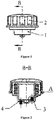
- Figure 1 is a schematic view of a tank cover of a urea tank for an SCR aftertreatment system provided by an embodiment of the present application
- Figure 2 is a sectional view taken along line B-B in Figure 1
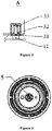
- Figure 3 is an enlarged view of portion A in Figure 2
- Figure 4 is a bottom view of Figure 1 .
- the tank cover provided by the embodiment of the present application is mounted at an liquid injection port of the urea tank body, and a ventilation hole is provided at a part of the tank cover corresponding to the liquid injection port, and the ventilation hole is covered by a water-impermeable and air-permeable membrane 5, as shown in Figure 4 .
- the air inlet hole (not denoted in the drawings) and the air outlet hole 11 are provided at the part of the tank cover corresponding to the liquid injection port.
- the first constant pressure check valve 3 and the second constant pressure check valve 4 are mounted on the tank cover, the inlet of the first constant pressure check valve 3 is butted with the air outlet hole 11, and the outlet of the first constant pressure check valve 3 is in communication with the outside of the tank body.
- the inlet of the second constant pressure check valve 4 is butted with the air inlet hole, and the outlet of the second constant pressure check valve 4 is in communication with the inside of the tank body.
- both the first constant pressure check valve 3 and the second constant pressure check valve 4 are closed.
- the air permeability of the water-impermeable and air-permeable membrane 5 is insufficient, for example, when the water-impermeable and air-permeable membrane 5 is submerged and blocked by outside rain, water, etc.
- the first constant pressure check valve 3 and the second constant pressure check valve 4 work in the following two situations respectively:
- the tank cover provided by the present application, the internal pressure and the external pressure of the tank body will not be seriously unbalanced due to insufficient air permeability of the water-impermeable and air-permeable membrane 5, thus the occurrence of deflation deformation or bulging deformation can be effectively avoided, and the urea tank is safer and more reliable.
- the pressure thresholds of the first constant pressure check valve 3 and the second constant pressure check valve 4 generally range from 3kPa to 5kPa. In order to set the pressure thresholds easily, both the first constant pressure check valve 3 and the second constant pressure check valve 4 can be designed with adjustable pressure thresholds.
- the tank cover includes a barrel-shaped inner shell 1 and a cap-shaped outer shell 2.
- the ventilation hole, the air inlet hole and the air outlet hole 11 are all arranged at the barrel bottom of the inner shell 1.
- a barrel mouth of the inner shell 1 is first folded outward, and then folded toward a barrel body of the inner shell 1 to form a cylindrical connecting portion.
- the outer shell 2 covers the connecting portion of the inner shell 1, a gap for ventilation is formed between an outer wall of the connecting portion and an inner wall of the outer shell 2, and an internal thread is provided at the inner wall of the connecting portion for connecting with the tank body.
- the first constant pressure check valve 3 and the second constant pressure check valve 4 are generally of the same type, that is, the first constant pressure check valve 3 and the second constant pressure check valve 4 have the same structure, and only need to be arranged in opposite directions during mounting. In this way, it can be ensured that the air has opposite circulation directions in the first constant pressure check valve 3 and the second constant pressure check valve 4, thus meeting the intake and exhaust requirements of the urea tank.
- the first constant pressure check valve 3 is taken as an example to introduce the specific structure of the constant pressure check valve designed in this embodiment.
- the first constant pressure check valve 3 includes a cylinder body (not marked in the Figure) and a baffle 31 provided in the cylinder body, and the baffle 31 is movably connected with the cylinder body.
- One end of the cylinder body is closed, a port at another end is the inlet of the first constant pressure check valve 3, and the outlet of the first constant pressure check valve 3 is provided on a wall of the cylinder body.
- the baffle 31 is configured to cover the inlet of the first constant pressure check valve 3, and an elastic member configured to reset the baffle 31 is arranged in the cylinder body.
- the elastic member is a spring, as shown in Figure 7 .
- the elastic member is a compression spring 32 sleeved on a valve rod 33.
- One end of the valve rod 33 is fixedly connected with the baffle 31, and the valve rod 33 is movably connected with the cylinder body.
- the baffle 31 is pressed against the port of the cylinder body (that is, the inlet of the first constant pressure check valve 3) under the action of the compression spring 32.
- the baffle 31 and the valve rod 33 may be integrally formed.
- the baffle 31 is generally made of rubber.
- a urea tank for an SCR aftertreatment system is further provided according to the present application, which includes the tank cover disclosed in the above embodiments. Since the tank cover disclosed in the above embodiments has the above technical effects, the urea tank with the tank cover also has the above technical effects, which will not be repeated here.
Landscapes
- Engineering & Computer Science (AREA)
- Chemical & Material Sciences (AREA)
- Combustion & Propulsion (AREA)
- Chemical Kinetics & Catalysis (AREA)
- Mechanical Engineering (AREA)
- Health & Medical Sciences (AREA)
- General Engineering & Computer Science (AREA)
- Sustainable Development (AREA)
- Transportation (AREA)
- Life Sciences & Earth Sciences (AREA)
- Sustainable Energy (AREA)
- Environmental & Geological Engineering (AREA)
- Biomedical Technology (AREA)
- Analytical Chemistry (AREA)
- General Chemical & Material Sciences (AREA)
- Oil, Petroleum & Natural Gas (AREA)
- Toxicology (AREA)
- Exhaust Gas After Treatment (AREA)
- Exhaust Gas Treatment By Means Of Catalyst (AREA)
Abstract
Description
- The present application relates to the technical field of diesel engines, and in particular to a urea tank for SCR aftertreatment system and a tank cover thereof.
- Nowadays, the laws and regulations on automobile emissions are becoming stricter and stricter, which also puts forward higher requirements for automobile exhaust aftertreatment. SCR catalytic reduction technology is an important technical route to reduce NOx emissions from diesel engines and meet China National IV standard and the above emission regulations.
- The SCR aftertreatment system includes a urea aqueous solution storage device called urea tank. The urea tank is mainly composed of a tank body, a tank cover and sensors. The urea tank needs to have ventilation function to ensure the balance of pressure inside and outside the tank body, which is generally realized by punching holes on the tank cover. In order to prevent dust from entering the urea tank through the ventilation hole and causing urea solution pollution, a water-impermeable and air-permeable membrane is covered on the ventilation hole.
- However, the ventilation capacity of the water-impermeable and air-permeable membrane is limited, and the air pressure and air flow rate of the air-assisted urea pump are relatively large during the power-off backblowing, so the water-impermeable and air-permeable membrane is easy to be blown out, thus losing its dustproof function. In addition, when outside rain and water accidentally enter the tank cover, the water-impermeable and air-permeable membrane is easily submerged and blocked, which leads to the failure of the air-permeable function. Therefore, when the urea pump draws urea from the urea tank, the suction resistance of the urea pump increases, which makes it difficult to build pressure, and the urea tank is deflated or even cracked; and when the (air-assisted) urea pump is powered off for back blowing, the high-pressure air delivered to the urea tank cannot be discharged in time, causing the urea tank to swell and burst.
- In summary, how to improve the reliability of the urea tank has become an urgent technical issue to be addressed by those skilled in the art.
- In view of this, a urea tank for SCR aftertreatment system and a tank cover thereof are provided according to the present application. The tank cover can make the urea tank safer and more reliable.
- In order to achieve the above object, the present application provides the following solutions.
- A tank cover of a urea tank for SCR aftertreatment system is provided. The tank cover is mounted at a liquid injection port of a urea tank body of the urea tank. A ventilation hole is provided at a part of the tank cover corresponding to the liquid injection port. The ventilation hole is covered by a water-impermeable and air-permeable membrane, and an air inlet hole and an air outlet hole are provided at the part of the tank cover corresponding to the liquid injection port. A first constant pressure check valve and a second constant pressure check valve are mounted on the tank cover. An inlet of the first constant pressure check valve is butted with the air outlet hole, and an outlet of the first constant pressure check valve is in communication with the outside of the tank body. An inlet of the second constant pressure check valve is butted with the air inlet hole, and an outlet of the second constant pressure check valve is in communication with the inside of the tank body.
- Preferably, in the tank cover, a pressure threshold of the first constant pressure check valve and a pressure threshold of the second constant pressure check valve are adjustable.
- Preferably, in the tank cover, the first constant pressure check valve includes a cylinder body and a baffle arranged in the cylinder body, the baffle is movably connected with the cylinder body, one end of the cylinder body is closed, a port at another end is the inlet of the first constant pressure check valve, and the outlet of the first constant pressure check valve is provided on a wall of the cylinder body; and
the baffle is configured to cover the inlet of the first constant pressure check valve, and an elastic member configured to reset the baffle is arranged in the cylinder body. - Preferably, in the tank cover, the elastic member is a spring.
- Preferably, in the tank cover, a valve rod movably connected with the cylinder body is arranged in the cylinder body, the baffle is fixedly connected with one end of the valve rod, and the elastic member is a compression spring sleeved on the valve rod.
- Preferably, in the tank cover, the second constant pressure check valve has the same structure as the first constant pressure check valve.
- Preferably, in the tank cover, the tank cover includes a barrel-shaped inner shell and a cap-shaped outer shell. The ventilation hole, the air inlet hole and the air outlet hole are all arranged at the barrel bottom of the inner shell. A barrel mouth of the inner shell is first folded outward, and then folded toward a barrel body of the inner shell to form a cylindrical connecting portion. The outer shell covers the connecting portion, a gap for ventilation is formed between an outer wall of the connecting portion and an inner wall of the outer shell, and an internal thread is provided at the inner wall of the connecting portion for connecting with the tank body.
- Preferably, in the tank cover, the baffle and the valve rod are integrally formed.
- Preferably, in the tank cover, the baffle is made of rubber.
- A urea tank for an SCR aftertreatment system is provided, which includes a tank cover, where the tank cover is the tank cover disclosed in any one of the above aspects.
- According to the above technical solution, in the tank cover of the urea tank for SCR aftertreatment system provided by the present application, the part of the tank cover corresponding to the liquid injection port of the tank body is not only provided with the ventilation hole, but also provided with the air inlet hole and the air outlet hole. The ventilation hole is covered by the water-impermeable and air-permeable membrane, the first constant pressure check valve is mounted at the air outlet hole, and the second constant pressure check valve is mounted at the air inlet hole. The inlet of the first constant pressure check valve is butted with the air outlet hole, and the outlet of the first constant pressure check valve is in communication with the outside of the tank body. The inlet of the second constant pressure check valve is butted with the air inlet hole, and the outlet of the second constant pressure check valve is in communication with the inside of the tank body.
- The tank cover is mounted at the liquid injection port of the tank body. When the water-impermeable and air-permeable membrane works normally, the membrane can provide the required ventilation function for the tank body. At this time, both the first constant pressure check valve and the second constant pressure check valve are closed. When the air permeability of the water-impermeable and air-permeable membrane is insufficient, for example, when the water-impermeable and air-permeable membrane is submerged and blocked by outside rain, water, etc., the pressure difference between inside and outside the tank body will increase no matter whether the urea pump sucks liquid from the tank body or the urea pump is powered off for back blowing. Once the pressure difference between inside and outside rises to the pressure threshold of the constant pressure check valve, the first constant pressure check valve or the second constant pressure check valve will be opened. In a case that the urea pump is powered off for back blowing, the first constant pressure check valve is opened, and the air inside the tank body can be discharged out of the tank body through the air outlet hole, so as to avoid cracking caused by bulging deformation of the tank body. In a case that the urea pump draws liquid from the tank body, the second constant pressure check valve is opened, and the air outside the tank body can enter the tank body through the air inlet hole to avoid the tank body from being deflated. Therefore, with the tank cover provided by the present application, the internal pressure and the external pressure of the tank body will not be seriously unbalanced due to insufficient air permeability of the water-impermeable and air-permeable membrane, thus the occurrence of deflation deformation or bulging deformation can be effectively avoided, and the urea tank is safer and more reliable.
- For more clearly illustrating embodiments of the present application or technical solutions in the conventional technology, the drawings referred to for describing the embodiments or the conventional technology will be briefly described hereinafter. Apparently, the drawings in the following description are only some examples of the present application, and for those skilled in the art, other drawings may be obtained based on the provided drawings without any creative efforts.
-
Figure 1 is a schematic view of a tank cover of a urea tank for an SCR aftertreatment system provided by an embodiment of the present application; -
Figure 2 is a sectional view taken along line B-B inFigure 1 ; -
Figure 3 is an enlarged view of portion A inFigure 2 ; -
Figure 4 is a bottom view ofFigure 1 ; -
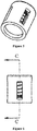
Figure 5 is a schematic perspective view of acomponent 3 inFigure 2 ; -
Figure 6 is a front view of thecomponent 3 inFigure 2 ; and -
Figure 7 is a sectional view taken along line C-C inFigure 6 . - Reference numerals in the drawings are as follows:
1 inner shell; 11 air outlet hole; 2 outer shell; 3 first constant pressure check valve; 31 baffle; 32 compression spring; 33 valve rod; 4 second constant pressure check valve; 5 water-impermeable and air-permeable membrane. - To facilitate understanding, the present application will be further described below in conjunction with the drawings.
- Referring to
Figures 1 to 4 ,Figure 1 is a schematic view of a tank cover of a urea tank for an SCR aftertreatment system provided by an embodiment of the present application,Figure 2 is a sectional view taken along line B-B inFigure 1 ,Figure 3 is an enlarged view of portion A inFigure 2 , andFigure 4 is a bottom view ofFigure 1 . - The tank cover provided by the embodiment of the present application is mounted at an liquid injection port of the urea tank body, and a ventilation hole is provided at a part of the tank cover corresponding to the liquid injection port, and the ventilation hole is covered by a water-impermeable and air-
permeable membrane 5, as shown inFigure 4 . Besides, the air inlet hole (not denoted in the drawings) and theair outlet hole 11 are provided at the part of the tank cover corresponding to the liquid injection port. As shown inFigure 2 andFigure 3 , the first constantpressure check valve 3 and the second constantpressure check valve 4 are mounted on the tank cover, the inlet of the first constantpressure check valve 3 is butted with theair outlet hole 11, and the outlet of the first constantpressure check valve 3 is in communication with the outside of the tank body. The inlet of the second constantpressure check valve 4 is butted with the air inlet hole, and the outlet of the second constantpressure check valve 4 is in communication with the inside of the tank body. - The working principle of the tank cover provided by the embodiments of the present application is as follows.
- When the water-impermeable and air-
permeable membrane 5 works normally, it can provide the required ventilation function for the tank body. At this time, both the first constantpressure check valve 3 and the second constantpressure check valve 4 are closed. When the air permeability of the water-impermeable and air-permeable membrane 5 is insufficient, for example, when the water-impermeable and air-permeable membrane 5 is submerged and blocked by outside rain, water, etc., the first constantpressure check valve 3 and the second constantpressure check valve 4 work in the following two situations respectively: - a) in the case that the urea pump is powered off for back blowing, the air pressure in the tank body gradually increases at the beginning, and the pressure difference between inside and outside the tank body increases accordingly, and when the pressure difference between inside and outside rises to the pressure threshold of the first constant
pressure check valve 3, the first constantpressure check valve 3 is opened under the pressure difference, so the air inside the tank body is discharged to the outside of the tank body through theair outlet hole 11 to avoid cracking caused by bulging deformation of the tank body; and - b) in the case that the urea pump sucks liquid from the tank body, the air pressure in the tank body gradually decreases at the beginning, which leads to the increase of pressure difference between inside and outside the tank body, and when the pressure difference between inside and outside rises to the pressure threshold of the second constant
pressure check valve 4, the second constantpressure check valve 4 is opened under the pressure difference, so the air outside the tank body enters the tank body through the air inlet hole to avoid the tank body from being deflated. - According to the above working principle, with the tank cover provided by the present application, the internal pressure and the external pressure of the tank body will not be seriously unbalanced due to insufficient air permeability of the water-impermeable and air-
permeable membrane 5, thus the occurrence of deflation deformation or bulging deformation can be effectively avoided, and the urea tank is safer and more reliable. - In practical application, the pressure thresholds of the first constant
pressure check valve 3 and the second constantpressure check valve 4 generally range from 3kPa to 5kPa. In order to set the pressure thresholds easily, both the first constantpressure check valve 3 and the second constantpressure check valve 4 can be designed with adjustable pressure thresholds. - Referring to
Figure 1 and Figure 2 , in this embodiment, the tank cover includes a barrel-shapedinner shell 1 and a cap-shapedouter shell 2. The ventilation hole, the air inlet hole and theair outlet hole 11 are all arranged at the barrel bottom of theinner shell 1. A barrel mouth of theinner shell 1 is first folded outward, and then folded toward a barrel body of theinner shell 1 to form a cylindrical connecting portion. Theouter shell 2 covers the connecting portion of theinner shell 1, a gap for ventilation is formed between an outer wall of the connecting portion and an inner wall of theouter shell 2, and an internal thread is provided at the inner wall of the connecting portion for connecting with the tank body. - For the convenience of manufacturing, the first constant
pressure check valve 3 and the second constantpressure check valve 4 are generally of the same type, that is, the first constantpressure check valve 3 and the second constantpressure check valve 4 have the same structure, and only need to be arranged in opposite directions during mounting. In this way, it can be ensured that the air has opposite circulation directions in the first constantpressure check valve 3 and the second constantpressure check valve 4, thus meeting the intake and exhaust requirements of the urea tank. - In the following, the first constant
pressure check valve 3 is taken as an example to introduce the specific structure of the constant pressure check valve designed in this embodiment. Referring toFigure 5 to Figure 7 , the first constantpressure check valve 3 includes a cylinder body (not marked in the Figure) and abaffle 31 provided in the cylinder body, and thebaffle 31 is movably connected with the cylinder body. One end of the cylinder body is closed, a port at another end is the inlet of the first constantpressure check valve 3, and the outlet of the first constantpressure check valve 3 is provided on a wall of the cylinder body. Thebaffle 31 is configured to cover the inlet of the first constantpressure check valve 3, and an elastic member configured to reset thebaffle 31 is arranged in the cylinder body. - In practical application, the elastic member is a spring, as shown in
Figure 7 . In this embodiment, the elastic member is acompression spring 32 sleeved on avalve rod 33. One end of thevalve rod 33 is fixedly connected with thebaffle 31, and thevalve rod 33 is movably connected with the cylinder body. Thebaffle 31 is pressed against the port of the cylinder body (that is, the inlet of the first constant pressure check valve 3) under the action of thecompression spring 32. As shown inFigure 2 andFigure 4 , in the case that the urea pump is powered off for back blowing, if the air permeability of the water-impermeable and air-permeable membrane 5 is insufficient, the pressure in the tank body of the urea tank will gradually increase, and as the pressure difference between inside and outside rises to the pressure threshold of the first constantpressure check valve 3, thebaffle 31 at the inlet of the first constantpressure check valve 3 will be pushed open. Therefore, the high-pressure air in the tank body is quickly exhausted from theair outlet hole 11, so as to avoid long-time excessive pressure in the tank body. - In practical application, the
baffle 31 and thevalve rod 33 may be integrally formed. In order to from close contact with the inlet of the first constantpressure check valve 3, thebaffle 31 is generally made of rubber. - A urea tank for an SCR aftertreatment system is further provided according to the present application, which includes the tank cover disclosed in the above embodiments. Since the tank cover disclosed in the above embodiments has the above technical effects, the urea tank with the tank cover also has the above technical effects, which will not be repeated here.
- According to the above description of the disclosed embodiments, those skilled in the art can implement or practice the present application. Various modifications to these embodiments will be apparent to those skilled in the art, and the general principles defined herein may be implemented in other embodiments without departing from the spirit or scope of the present application. Therefore, the present application shall not be limited to the embodiments illustrated herein, but shall conform to the widest scope consistent with the principles and novel features disclosed herein.
Claims (10)
- A tank cover of a urea tank for SCR aftertreatment system, wherein the tank cover is mounted at a liquid injection port of a urea tank body of the urea tank, a ventilation hole is provided at a part of the tank cover corresponding to the liquid injection port, the ventilation hole is covered by a water-impermeable and air-permeable membrane (5),
an air inlet hole and an air outlet hole (11) are provided at the part of the tank cover corresponding to the liquid injection port, a first constant pressure check valve (3) and a second constant pressure check valve (4) are mounted on the tank cover,
an inlet of the first constant pressure check valve (3) is butted with the air outlet hole (11), and an outlet of the first constant pressure check valve (3) is in communication with outside of the tank body,
an inlet of the second constant pressure check valve (4) is butted with the air inlet hole, and an outlet of the second constant pressure check valve (4) is in communication with inside of the tank body. - The tank cover according to claim 1, wherein a pressure threshold of the first constant pressure check valve (3) and a pressure threshold of the second constant pressure check valve (4) are adjustable.
- The tank cover according to claim 1, wherein the first constant pressure check valve (3) comprises a cylinder body and a baffle (31) arranged in the cylinder body, the baffle (31) is movably connected with the cylinder body, one end of the cylinder body is closed, a port at another end is the inlet of the first constant pressure check valve (3), and the outlet of the first constant pressure check valve (3) is provided on a wall of the cylinder body; and
the baffle (31) is configured to cover the inlet of the first constant pressure check valve (3), and an elastic member configured to reset the baffle (31) is arranged in the cylinder body. - The tank cover according to claim 3, wherein the elastic member is a spring.
- The tank cover according to claim 4, wherein a valve rod (33) movably connected with the cylinder body is arranged in the cylinder body, the baffle (31) is fixedly connected with one end of the valve rod (33), and the elastic member is a compression spring (32) sleeved on the valve rod (33).
- The tank cover according to any one of claims 1 to 5, wherein the second constant pressure check valve (4) has a same structure as the first constant pressure check valve (3).
- The tank cover according to claim 6, wherein the tank cover comprises a barrel-shaped inner shell (1) and a cap-shaped outer shell (2),
the ventilation hole, the air inlet hole and the air outlet hole (11) are all arranged at a barrel bottom of the inner shell (1),
a barrel mouth of the inner shell (1) is first folded outward, and then folded toward a barrel body of the inner shell (1) to form a cylindrical connecting portion, and the outer shell (2) covers the connecting portion,
a gap for ventilation is formed between an outer wall of the connecting portion and an inner wall of the outer shell (2), and an internal thread is provided at the inner wall of the connecting portion for connecting with the tank body. - The tank cover according to claim 7, wherein the baffle (31) and the valve rod (33) are integrally formed.
- The tank cover according to claim 7, wherein the baffle (31) is made of rubber.
- A urea tank for an SCR aftertreatment system comprising the tank cover according to any one of claims 1 to 9.
Applications Claiming Priority (1)
| Application Number | Priority Date | Filing Date | Title |
|---|---|---|---|
| PCT/CN2018/108515 WO2020062118A1 (en) | 2018-09-29 | 2018-09-29 | Urea tank for scr aftertreatment system, and tank cover thereof |
Publications (3)
| Publication Number | Publication Date |
|---|---|
| EP3859129A1 true EP3859129A1 (en) | 2021-08-04 |
| EP3859129A4 EP3859129A4 (en) | 2022-05-11 |
| EP3859129B1 EP3859129B1 (en) | 2022-12-21 |
Family
ID=69949863
Family Applications (1)
| Application Number | Title | Priority Date | Filing Date |
|---|---|---|---|
| EP18934577.0A Active EP3859129B1 (en) | 2018-09-29 | 2018-09-29 | Urea tank for scr aftertreatment system, and tank cover thereof |
Country Status (6)
| Country | Link |
|---|---|
| US (1) | US12109533B2 (en) |
| EP (1) | EP3859129B1 (en) |
| CN (1) | CN111971460B (en) |
| SG (1) | SG11202102763YA (en) |
| UA (1) | UA126319C2 (en) |
| WO (1) | WO2020062118A1 (en) |
Families Citing this family (1)
| Publication number | Priority date | Publication date | Assignee | Title |
|---|---|---|---|---|
| USD1033779S1 (en) * | 2022-08-17 | 2024-07-02 | Shiji Qu | Vacuum extractor seal tool cover |
Family Cites Families (17)
| Publication number | Priority date | Publication date | Assignee | Title |
|---|---|---|---|---|
| GB613386A (en) | 1946-06-20 | 1948-11-25 | Enfield Cycle Co Ltd | An improved valve system or "breather" for use in connection with the crank cases of internal combustion engines |
| JP3811839B2 (en) * | 1999-05-13 | 2006-08-23 | 敏雄 矢野 | Air valve |
| US20070277505A1 (en) * | 2006-05-30 | 2007-12-06 | Ford Global Technologies, Llc | Venting of on-board vehicle emissions treatment system |
| DE102010047348A1 (en) | 2010-10-02 | 2012-04-05 | Volkswagen Ag | Pressure balancing device for container e.g. plastic container used for storing aqueous urea solution, has semipermeable membrane through which only gas can pass, and connecting device that serves as cap for container |
| CN201896653U (en) * | 2010-11-19 | 2011-07-13 | 东莞正扬电子机械有限公司 | Anti-splash air valve for urea tank |
| CN102022164A (en) * | 2010-12-15 | 2011-04-20 | 中国第一汽车集团公司 | Selective catalyst reduction (SCR) urea tank for after-treatment of exhaust gas of diesel engine |
| DE102011009216B4 (en) * | 2011-01-22 | 2024-03-14 | Volkswagen Aktiengesellschaft | Reducing agent storage system for an SCR exhaust system |
| DE202011004562U1 (en) | 2011-03-29 | 2011-06-09 | MAGNA STEYR Fuel Systems GmbH, 41516 | filler cap |
| CN103814194B (en) | 2011-08-22 | 2016-10-19 | 康明斯排放处理公司 | The device of carbamide dosing, method and system for exhaust after treatment system |
| DE102013101282A1 (en) | 2013-02-08 | 2014-08-14 | Emitec Gesellschaft Für Emissionstechnologie Mbh | Dosing valve for freeze-risk additives |
| CN203499776U (en) * | 2013-09-30 | 2014-03-26 | 天津亿利汽车环保科技有限公司 | Urea tank in urea injection system |
| CN104214379B (en) * | 2014-01-26 | 2016-08-31 | 东莞正扬电子机械有限公司 | Urea box and anti-leak breather valve thereof |
| JP5940107B2 (en) * | 2014-03-17 | 2016-06-29 | 日立建機株式会社 | Urea water supply system for construction machinery |
| CN104373178B (en) * | 2014-10-29 | 2017-02-22 | 凯龙高科技股份有限公司 | Urea solution tank filling assembly used for SCR system |
| DE102015105675B3 (en) | 2015-04-14 | 2016-09-15 | Reutter Gmbh | Tank cap, especially SCR closure |
| JP6228159B2 (en) * | 2015-05-27 | 2017-11-08 | トヨタ自動車株式会社 | Urea water supply device for internal combustion engine |
| CN204961031U (en) * | 2015-08-12 | 2016-01-13 | 潍柴动力股份有限公司 | Urea case filling mechanism |
-
2018
- 2018-09-29 WO PCT/CN2018/108515 patent/WO2020062118A1/en not_active Ceased
- 2018-09-29 UA UAA202102150A patent/UA126319C2/en unknown
- 2018-09-29 SG SG11202102763YA patent/SG11202102763YA/en unknown
- 2018-09-29 US US17/278,623 patent/US12109533B2/en active Active
- 2018-09-29 EP EP18934577.0A patent/EP3859129B1/en active Active
- 2018-09-29 CN CN201880092398.2A patent/CN111971460B/en active Active
Also Published As
| Publication number | Publication date |
|---|---|
| US12109533B2 (en) | 2024-10-08 |
| UA126319C2 (en) | 2022-09-14 |
| CN111971460A (en) | 2020-11-20 |
| SG11202102763YA (en) | 2021-04-29 |
| CN111971460B (en) | 2022-07-15 |
| EP3859129A4 (en) | 2022-05-11 |
| EP3859129B1 (en) | 2022-12-21 |
| US20220040638A1 (en) | 2022-02-10 |
| WO2020062118A1 (en) | 2020-04-02 |
Similar Documents
| Publication | Publication Date | Title |
|---|---|---|
| EP3859129B1 (en) | Urea tank for scr aftertreatment system, and tank cover thereof | |
| CN110005556B (en) | Oil inlet structure of two-stroke gasoline engine | |
| CN201934213U (en) | Fuel adsorbing device | |
| CN102817679A (en) | Anti-overfilling urea box | |
| CN201896653U (en) | Anti-splash air valve for urea tank | |
| CN219375629U (en) | Integrated breast pump | |
| CN207028835U (en) | Fuel tank and vehicle | |
| CN210600192U (en) | Limiting air valve with good sealing performance | |
| RU2774133C1 (en) | Container with urea for an scr post-treatment system and cover for the container | |
| CN219699837U (en) | Water tank assembly and cleaning robot | |
| CN202789032U (en) | Anti-overfilled urea tank | |
| CN218818395U (en) | Oil tank ventilation cover | |
| CN209800141U (en) | Oil inlet structure of two-stroke gasoline engine | |
| CN210239777U (en) | Engine oil pan and engine | |
| CN208069643U (en) | Integrated air cylinder | |
| CN210948952U (en) | Self-priming pump device of fuel pump bracket assembly | |
| CN109129257B (en) | Suction pen with fool-proof function | |
| CN209100118U (en) | A kind of aerating system of solution storage box | |
| CN217275101U (en) | A kind of refrigerator | |
| CN221308077U (en) | Handheld dust collector | |
| CN220909872U (en) | Fuel pump with hydrops function | |
| CN116480504B (en) | Pump core fuel supply dual injection pump with check valve and filter structure fuel pump assembly | |
| CN216279568U (en) | A flat top check valve | |
| US20250049273A1 (en) | Window cleaning robot | |
| CN223667832U (en) | Air suction structure of electric body cleaner |
Legal Events
| Date | Code | Title | Description |
|---|---|---|---|
| STAA | Information on the status of an ep patent application or granted ep patent |
Free format text: STATUS: THE INTERNATIONAL PUBLICATION HAS BEEN MADE |
|
| PUAI | Public reference made under article 153(3) epc to a published international application that has entered the european phase |
Free format text: ORIGINAL CODE: 0009012 |
|
| STAA | Information on the status of an ep patent application or granted ep patent |
Free format text: STATUS: REQUEST FOR EXAMINATION WAS MADE |
|
| 17P | Request for examination filed |
Effective date: 20210301 |
|
| AK | Designated contracting states |
Kind code of ref document: A1 Designated state(s): AL AT BE BG CH CY CZ DE DK EE ES FI FR GB GR HR HU IE IS IT LI LT LU LV MC MK MT NL NO PL PT RO RS SE SI SK SM TR |
|
| DAV | Request for validation of the european patent (deleted) | ||
| DAX | Request for extension of the european patent (deleted) | ||
| A4 | Supplementary search report drawn up and despatched |
Effective date: 20220412 |
|
| RIC1 | Information provided on ipc code assigned before grant |
Ipc: B60K 15/04 20060101ALI20220406BHEP Ipc: B01D 53/94 20060101ALI20220406BHEP Ipc: F01N 3/28 20060101AFI20220406BHEP |
|
| GRAP | Despatch of communication of intention to grant a patent |
Free format text: ORIGINAL CODE: EPIDOSNIGR1 |
|
| STAA | Information on the status of an ep patent application or granted ep patent |
Free format text: STATUS: GRANT OF PATENT IS INTENDED |
|
| INTG | Intention to grant announced |
Effective date: 20220712 |
|
| GRAS | Grant fee paid |
Free format text: ORIGINAL CODE: EPIDOSNIGR3 |
|
| GRAA | (expected) grant |
Free format text: ORIGINAL CODE: 0009210 |
|
| STAA | Information on the status of an ep patent application or granted ep patent |
Free format text: STATUS: THE PATENT HAS BEEN GRANTED |
|
| AK | Designated contracting states |
Kind code of ref document: B1 Designated state(s): AL AT BE BG CH CY CZ DE DK EE ES FI FR GB GR HR HU IE IS IT LI LT LU LV MC MK MT NL NO PL PT RO RS SE SI SK SM TR |
|
| REG | Reference to a national code |
Ref country code: GB Ref legal event code: FG4D |
|
| REG | Reference to a national code |
Ref country code: DE Ref legal event code: R096 Ref document number: 602018044617 Country of ref document: DE |
|
| REG | Reference to a national code |
Ref country code: CH Ref legal event code: EP |
|
| REG | Reference to a national code |
Ref country code: AT Ref legal event code: REF Ref document number: 1539184 Country of ref document: AT Kind code of ref document: T Effective date: 20230115 |
|
| REG | Reference to a national code |
Ref country code: IE Ref legal event code: FG4D |
|
| REG | Reference to a national code |
Ref country code: LT Ref legal event code: MG9D |
|
| REG | Reference to a national code |
Ref country code: NL Ref legal event code: MP Effective date: 20221221 |
|
| PG25 | Lapsed in a contracting state [announced via postgrant information from national office to epo] |
Ref country code: SE Free format text: LAPSE BECAUSE OF FAILURE TO SUBMIT A TRANSLATION OF THE DESCRIPTION OR TO PAY THE FEE WITHIN THE PRESCRIBED TIME-LIMIT Effective date: 20221221 Ref country code: NO Free format text: LAPSE BECAUSE OF FAILURE TO SUBMIT A TRANSLATION OF THE DESCRIPTION OR TO PAY THE FEE WITHIN THE PRESCRIBED TIME-LIMIT Effective date: 20230321 Ref country code: LT Free format text: LAPSE BECAUSE OF FAILURE TO SUBMIT A TRANSLATION OF THE DESCRIPTION OR TO PAY THE FEE WITHIN THE PRESCRIBED TIME-LIMIT Effective date: 20221221 Ref country code: FI Free format text: LAPSE BECAUSE OF FAILURE TO SUBMIT A TRANSLATION OF THE DESCRIPTION OR TO PAY THE FEE WITHIN THE PRESCRIBED TIME-LIMIT Effective date: 20221221 |
|
| REG | Reference to a national code |
Ref country code: AT Ref legal event code: MK05 Ref document number: 1539184 Country of ref document: AT Kind code of ref document: T Effective date: 20221221 |
|
| PG25 | Lapsed in a contracting state [announced via postgrant information from national office to epo] |
Ref country code: RS Free format text: LAPSE BECAUSE OF FAILURE TO SUBMIT A TRANSLATION OF THE DESCRIPTION OR TO PAY THE FEE WITHIN THE PRESCRIBED TIME-LIMIT Effective date: 20221221 Ref country code: LV Free format text: LAPSE BECAUSE OF FAILURE TO SUBMIT A TRANSLATION OF THE DESCRIPTION OR TO PAY THE FEE WITHIN THE PRESCRIBED TIME-LIMIT Effective date: 20221221 Ref country code: HR Free format text: LAPSE BECAUSE OF FAILURE TO SUBMIT A TRANSLATION OF THE DESCRIPTION OR TO PAY THE FEE WITHIN THE PRESCRIBED TIME-LIMIT Effective date: 20221221 Ref country code: GR Free format text: LAPSE BECAUSE OF FAILURE TO SUBMIT A TRANSLATION OF THE DESCRIPTION OR TO PAY THE FEE WITHIN THE PRESCRIBED TIME-LIMIT Effective date: 20230322 |
|
| PG25 | Lapsed in a contracting state [announced via postgrant information from national office to epo] |
Ref country code: NL Free format text: LAPSE BECAUSE OF FAILURE TO SUBMIT A TRANSLATION OF THE DESCRIPTION OR TO PAY THE FEE WITHIN THE PRESCRIBED TIME-LIMIT Effective date: 20221221 |
|
| PG25 | Lapsed in a contracting state [announced via postgrant information from national office to epo] |
Ref country code: SM Free format text: LAPSE BECAUSE OF FAILURE TO SUBMIT A TRANSLATION OF THE DESCRIPTION OR TO PAY THE FEE WITHIN THE PRESCRIBED TIME-LIMIT Effective date: 20221221 Ref country code: RO Free format text: LAPSE BECAUSE OF FAILURE TO SUBMIT A TRANSLATION OF THE DESCRIPTION OR TO PAY THE FEE WITHIN THE PRESCRIBED TIME-LIMIT Effective date: 20221221 Ref country code: PT Free format text: LAPSE BECAUSE OF FAILURE TO SUBMIT A TRANSLATION OF THE DESCRIPTION OR TO PAY THE FEE WITHIN THE PRESCRIBED TIME-LIMIT Effective date: 20230421 Ref country code: ES Free format text: LAPSE BECAUSE OF FAILURE TO SUBMIT A TRANSLATION OF THE DESCRIPTION OR TO PAY THE FEE WITHIN THE PRESCRIBED TIME-LIMIT Effective date: 20221221 Ref country code: EE Free format text: LAPSE BECAUSE OF FAILURE TO SUBMIT A TRANSLATION OF THE DESCRIPTION OR TO PAY THE FEE WITHIN THE PRESCRIBED TIME-LIMIT Effective date: 20221221 Ref country code: CZ Free format text: LAPSE BECAUSE OF FAILURE TO SUBMIT A TRANSLATION OF THE DESCRIPTION OR TO PAY THE FEE WITHIN THE PRESCRIBED TIME-LIMIT Effective date: 20221221 Ref country code: AT Free format text: LAPSE BECAUSE OF FAILURE TO SUBMIT A TRANSLATION OF THE DESCRIPTION OR TO PAY THE FEE WITHIN THE PRESCRIBED TIME-LIMIT Effective date: 20221221 |
|
| PG25 | Lapsed in a contracting state [announced via postgrant information from national office to epo] |
Ref country code: SK Free format text: LAPSE BECAUSE OF FAILURE TO SUBMIT A TRANSLATION OF THE DESCRIPTION OR TO PAY THE FEE WITHIN THE PRESCRIBED TIME-LIMIT Effective date: 20221221 Ref country code: PL Free format text: LAPSE BECAUSE OF FAILURE TO SUBMIT A TRANSLATION OF THE DESCRIPTION OR TO PAY THE FEE WITHIN THE PRESCRIBED TIME-LIMIT Effective date: 20221221 Ref country code: IS Free format text: LAPSE BECAUSE OF FAILURE TO SUBMIT A TRANSLATION OF THE DESCRIPTION OR TO PAY THE FEE WITHIN THE PRESCRIBED TIME-LIMIT Effective date: 20230421 Ref country code: AL Free format text: LAPSE BECAUSE OF FAILURE TO SUBMIT A TRANSLATION OF THE DESCRIPTION OR TO PAY THE FEE WITHIN THE PRESCRIBED TIME-LIMIT Effective date: 20221221 |
|
| REG | Reference to a national code |
Ref country code: DE Ref legal event code: R097 Ref document number: 602018044617 Country of ref document: DE |
|
| PLBE | No opposition filed within time limit |
Free format text: ORIGINAL CODE: 0009261 |
|
| STAA | Information on the status of an ep patent application or granted ep patent |
Free format text: STATUS: NO OPPOSITION FILED WITHIN TIME LIMIT |
|
| PG25 | Lapsed in a contracting state [announced via postgrant information from national office to epo] |
Ref country code: DK Free format text: LAPSE BECAUSE OF FAILURE TO SUBMIT A TRANSLATION OF THE DESCRIPTION OR TO PAY THE FEE WITHIN THE PRESCRIBED TIME-LIMIT Effective date: 20221221 |
|
| 26N | No opposition filed |
Effective date: 20230922 |
|
| PG25 | Lapsed in a contracting state [announced via postgrant information from national office to epo] |
Ref country code: SI Free format text: LAPSE BECAUSE OF FAILURE TO SUBMIT A TRANSLATION OF THE DESCRIPTION OR TO PAY THE FEE WITHIN THE PRESCRIBED TIME-LIMIT Effective date: 20221221 |
|
| REG | Reference to a national code |
Ref country code: CH Ref legal event code: PL |
|
| PG25 | Lapsed in a contracting state [announced via postgrant information from national office to epo] |
Ref country code: LU Free format text: LAPSE BECAUSE OF NON-PAYMENT OF DUE FEES Effective date: 20230929 |
|
| REG | Reference to a national code |
Ref country code: BE Ref legal event code: MM Effective date: 20230930 |
|
| PG25 | Lapsed in a contracting state [announced via postgrant information from national office to epo] |
Ref country code: LU Free format text: LAPSE BECAUSE OF NON-PAYMENT OF DUE FEES Effective date: 20230929 Ref country code: IT Free format text: LAPSE BECAUSE OF FAILURE TO SUBMIT A TRANSLATION OF THE DESCRIPTION OR TO PAY THE FEE WITHIN THE PRESCRIBED TIME-LIMIT Effective date: 20221221 Ref country code: MC Free format text: LAPSE BECAUSE OF FAILURE TO SUBMIT A TRANSLATION OF THE DESCRIPTION OR TO PAY THE FEE WITHIN THE PRESCRIBED TIME-LIMIT Effective date: 20221221 |
|
| REG | Reference to a national code |
Ref country code: IE Ref legal event code: MM4A |
|
| PG25 | Lapsed in a contracting state [announced via postgrant information from national office to epo] |
Ref country code: IE Free format text: LAPSE BECAUSE OF NON-PAYMENT OF DUE FEES Effective date: 20230929 |
|
| PG25 | Lapsed in a contracting state [announced via postgrant information from national office to epo] |
Ref country code: CH Free format text: LAPSE BECAUSE OF NON-PAYMENT OF DUE FEES Effective date: 20230930 |
|
| PG25 | Lapsed in a contracting state [announced via postgrant information from national office to epo] |
Ref country code: IE Free format text: LAPSE BECAUSE OF NON-PAYMENT OF DUE FEES Effective date: 20230929 Ref country code: CH Free format text: LAPSE BECAUSE OF NON-PAYMENT OF DUE FEES Effective date: 20230930 |
|
| PG25 | Lapsed in a contracting state [announced via postgrant information from national office to epo] |
Ref country code: BE Free format text: LAPSE BECAUSE OF NON-PAYMENT OF DUE FEES Effective date: 20230930 |
|
| PG25 | Lapsed in a contracting state [announced via postgrant information from national office to epo] |
Ref country code: BG Free format text: LAPSE BECAUSE OF FAILURE TO SUBMIT A TRANSLATION OF THE DESCRIPTION OR TO PAY THE FEE WITHIN THE PRESCRIBED TIME-LIMIT Effective date: 20221221 |
|
| PG25 | Lapsed in a contracting state [announced via postgrant information from national office to epo] |
Ref country code: BG Free format text: LAPSE BECAUSE OF FAILURE TO SUBMIT A TRANSLATION OF THE DESCRIPTION OR TO PAY THE FEE WITHIN THE PRESCRIBED TIME-LIMIT Effective date: 20221221 |
|
| PG25 | Lapsed in a contracting state [announced via postgrant information from national office to epo] |
Ref country code: CY Free format text: LAPSE BECAUSE OF FAILURE TO SUBMIT A TRANSLATION OF THE DESCRIPTION OR TO PAY THE FEE WITHIN THE PRESCRIBED TIME-LIMIT; INVALID AB INITIO Effective date: 20180929 |
|
| PG25 | Lapsed in a contracting state [announced via postgrant information from national office to epo] |
Ref country code: HU Free format text: LAPSE BECAUSE OF FAILURE TO SUBMIT A TRANSLATION OF THE DESCRIPTION OR TO PAY THE FEE WITHIN THE PRESCRIBED TIME-LIMIT; INVALID AB INITIO Effective date: 20180929 |
|
| PGFP | Annual fee paid to national office [announced via postgrant information from national office to epo] |
Ref country code: FR Payment date: 20250930 Year of fee payment: 8 |
|
| PG25 | Lapsed in a contracting state [announced via postgrant information from national office to epo] |
Ref country code: TR Free format text: LAPSE BECAUSE OF FAILURE TO SUBMIT A TRANSLATION OF THE DESCRIPTION OR TO PAY THE FEE WITHIN THE PRESCRIBED TIME-LIMIT Effective date: 20221221 |
|
| PGFP | Annual fee paid to national office [announced via postgrant information from national office to epo] |
Ref country code: DE Payment date: 20251015 Year of fee payment: 8 |
|
| PGFP | Annual fee paid to national office [announced via postgrant information from national office to epo] |
Ref country code: GB Payment date: 20251023 Year of fee payment: 8 |