EP3859064A1 - Partially split fiber bundle and production method therefor - Google Patents
Partially split fiber bundle and production method therefor Download PDFInfo
- Publication number
- EP3859064A1 EP3859064A1 EP19864138.3A EP19864138A EP3859064A1 EP 3859064 A1 EP3859064 A1 EP 3859064A1 EP 19864138 A EP19864138 A EP 19864138A EP 3859064 A1 EP3859064 A1 EP 3859064A1
- Authority
- EP
- European Patent Office
- Prior art keywords
- fiber
- fiber bundle
- partially separated
- units
- bundle
- Prior art date
- Legal status (The legal status is an assumption and is not a legal conclusion. Google has not performed a legal analysis and makes no representation as to the accuracy of the status listed.)
- Pending
Links
- 239000000835 fiber Substances 0.000 title claims abstract description 617
- 238000004519 manufacturing process Methods 0.000 title claims abstract description 33
- 239000003795 chemical substances by application Substances 0.000 claims description 81
- 238000004513 sizing Methods 0.000 claims description 81
- 238000000034 method Methods 0.000 claims description 59
- 238000001035 drying Methods 0.000 claims description 18
- 229920000049 Carbon (fiber) Polymers 0.000 claims description 17
- 239000004917 carbon fiber Substances 0.000 claims description 17
- 239000003822 epoxy resin Substances 0.000 claims description 9
- 229920000647 polyepoxide Polymers 0.000 claims description 9
- 229920006122 polyamide resin Polymers 0.000 claims description 7
- 229920005989 resin Polymers 0.000 abstract description 37
- 239000011347 resin Substances 0.000 abstract description 37
- 239000012778 molding material Substances 0.000 abstract description 17
- 238000000926 separation method Methods 0.000 description 50
- 239000000463 material Substances 0.000 description 24
- 238000011144 upstream manufacturing Methods 0.000 description 21
- 239000012783 reinforcing fiber Substances 0.000 description 18
- VNWKTOKETHGBQD-UHFFFAOYSA-N methane Chemical compound C VNWKTOKETHGBQD-UHFFFAOYSA-N 0.000 description 13
- 239000011248 coating agent Substances 0.000 description 11
- 238000000576 coating method Methods 0.000 description 11
- 239000011159 matrix material Substances 0.000 description 11
- 238000005259 measurement Methods 0.000 description 11
- 229920005992 thermoplastic resin Polymers 0.000 description 10
- 230000000052 comparative effect Effects 0.000 description 8
- 238000005452 bending Methods 0.000 description 7
- 229920002647 polyamide Polymers 0.000 description 6
- 230000001360 synchronised effect Effects 0.000 description 6
- 239000004952 Polyamide Substances 0.000 description 5
- 238000007334 copolymerization reaction Methods 0.000 description 5
- -1 for example) Substances 0.000 description 5
- XLYOFNOQVPJJNP-UHFFFAOYSA-N water Substances O XLYOFNOQVPJJNP-UHFFFAOYSA-N 0.000 description 5
- 229920001155 polypropylene Polymers 0.000 description 4
- QTBSBXVTEAMEQO-UHFFFAOYSA-N Acetic acid Chemical compound CC(O)=O QTBSBXVTEAMEQO-UHFFFAOYSA-N 0.000 description 3
- MUBZPKHOEPUJKR-UHFFFAOYSA-N Oxalic acid Chemical compound OC(=O)C(O)=O MUBZPKHOEPUJKR-UHFFFAOYSA-N 0.000 description 3
- 239000004743 Polypropylene Substances 0.000 description 3
- 238000009825 accumulation Methods 0.000 description 3
- 239000002131 composite material Substances 0.000 description 3
- 230000000694 effects Effects 0.000 description 3
- 238000011156 evaluation Methods 0.000 description 3
- 238000000465 moulding Methods 0.000 description 3
- 239000004745 nonwoven fabric Substances 0.000 description 3
- 230000000704 physical effect Effects 0.000 description 3
- 229920002239 polyacrylonitrile Polymers 0.000 description 3
- 238000004804 winding Methods 0.000 description 3
- VEXZGXHMUGYJMC-UHFFFAOYSA-N Hydrochloric acid Chemical compound Cl VEXZGXHMUGYJMC-UHFFFAOYSA-N 0.000 description 2
- OFOBLEOULBTSOW-UHFFFAOYSA-N Malonic acid Chemical compound OC(=O)CC(O)=O OFOBLEOULBTSOW-UHFFFAOYSA-N 0.000 description 2
- 239000004594 Masterbatch (MB) Substances 0.000 description 2
- NBIIXXVUZAFLBC-UHFFFAOYSA-N Phosphoric acid Chemical compound OP(O)(O)=O NBIIXXVUZAFLBC-UHFFFAOYSA-N 0.000 description 2
- QAOWNCQODCNURD-UHFFFAOYSA-N Sulfuric acid Chemical compound OS(O)(=O)=O QAOWNCQODCNURD-UHFFFAOYSA-N 0.000 description 2
- 238000010521 absorption reaction Methods 0.000 description 2
- WNLRTRBMVRJNCN-UHFFFAOYSA-N adipic acid Chemical compound OC(=O)CCCCC(O)=O WNLRTRBMVRJNCN-UHFFFAOYSA-N 0.000 description 2
- 230000003466 anti-cipated effect Effects 0.000 description 2
- IISBACLAFKSPIT-UHFFFAOYSA-N bisphenol A Chemical compound C=1C=C(O)C=CC=1C(C)(C)C1=CC=C(O)C=C1 IISBACLAFKSPIT-UHFFFAOYSA-N 0.000 description 2
- PXKLMJQFEQBVLD-UHFFFAOYSA-N bisphenol F Chemical compound C1=CC(O)=CC=C1CC1=CC=C(O)C=C1 PXKLMJQFEQBVLD-UHFFFAOYSA-N 0.000 description 2
- 239000011197 carbon fiber sheet molding compound Substances 0.000 description 2
- 238000010586 diagram Methods 0.000 description 2
- 150000004985 diamines Chemical class 0.000 description 2
- XBDQKXXYIPTUBI-UHFFFAOYSA-N dimethylselenoniopropionate Natural products CCC(O)=O XBDQKXXYIPTUBI-UHFFFAOYSA-N 0.000 description 2
- 238000005516 engineering process Methods 0.000 description 2
- JBKVHLHDHHXQEQ-UHFFFAOYSA-N epsilon-caprolactam Chemical compound O=C1CCCCCN1 JBKVHLHDHHXQEQ-UHFFFAOYSA-N 0.000 description 2
- QEWYKACRFQMRMB-UHFFFAOYSA-N fluoroacetic acid Chemical compound OC(=O)CF QEWYKACRFQMRMB-UHFFFAOYSA-N 0.000 description 2
- 150000003951 lactams Chemical class 0.000 description 2
- 239000002184 metal Substances 0.000 description 2
- 150000007522 mineralic acids Chemical class 0.000 description 2
- 150000007524 organic acids Chemical class 0.000 description 2
- 125000006353 oxyethylene group Chemical group 0.000 description 2
- 229920000642 polymer Polymers 0.000 description 2
- CXMXRPHRNRROMY-UHFFFAOYSA-N sebacic acid Chemical compound OC(=O)CCCCCCCCC(O)=O CXMXRPHRNRROMY-UHFFFAOYSA-N 0.000 description 2
- 125000001302 tertiary amino group Chemical group 0.000 description 2
- XUSNPFGLKGCWGN-UHFFFAOYSA-N 3-[4-(3-aminopropyl)piperazin-1-yl]propan-1-amine Chemical compound NCCCN1CCN(CCCN)CC1 XUSNPFGLKGCWGN-UHFFFAOYSA-N 0.000 description 1
- FGSUUFDRDVJCLT-UHFFFAOYSA-N 3-methylazepan-2-one Chemical compound CC1CCCCNC1=O FGSUUFDRDVJCLT-UHFFFAOYSA-N 0.000 description 1
- YLIIGKBLXUJUIG-UHFFFAOYSA-N 7-hexylazepan-2-one Chemical compound CCCCCCC1CCCCC(=O)N1 YLIIGKBLXUJUIG-UHFFFAOYSA-N 0.000 description 1
- JAWSTIJAWZBKOU-UHFFFAOYSA-N 7-methylazepan-2-one Chemical compound CC1CCCCC(=O)N1 JAWSTIJAWZBKOU-UHFFFAOYSA-N 0.000 description 1
- 229920002292 Nylon 6 Polymers 0.000 description 1
- 239000004962 Polyamide-imide Substances 0.000 description 1
- 239000004642 Polyimide Substances 0.000 description 1
- 229920000297 Rayon Polymers 0.000 description 1
- 239000002253 acid Substances 0.000 description 1
- 239000001361 adipic acid Substances 0.000 description 1
- 235000011037 adipic acid Nutrition 0.000 description 1
- 125000001931 aliphatic group Chemical group 0.000 description 1
- 229910000147 aluminium phosphate Inorganic materials 0.000 description 1
- 125000003277 amino group Chemical group 0.000 description 1
- IMUDHTPIFIBORV-UHFFFAOYSA-N aminoethylpiperazine Chemical compound NCCN1CCNCC1 IMUDHTPIFIBORV-UHFFFAOYSA-N 0.000 description 1
- 229920006231 aramid fiber Polymers 0.000 description 1
- 239000012298 atmosphere Substances 0.000 description 1
- 238000012660 binary copolymerization Methods 0.000 description 1
- 238000004364 calculation method Methods 0.000 description 1
- 125000003178 carboxy group Chemical group [H]OC(*)=O 0.000 description 1
- 150000001732 carboxylic acid derivatives Chemical class 0.000 description 1
- FOCAUTSVDIKZOP-UHFFFAOYSA-N chloroacetic acid Chemical compound OC(=O)CCl FOCAUTSVDIKZOP-UHFFFAOYSA-N 0.000 description 1
- 229940106681 chloroacetic acid Drugs 0.000 description 1
- 150000001875 compounds Chemical class 0.000 description 1
- 229920001577 copolymer Polymers 0.000 description 1
- 238000009826 distribution Methods 0.000 description 1
- 125000003700 epoxy group Chemical group 0.000 description 1
- 239000012467 final product Substances 0.000 description 1
- 125000000524 functional group Chemical group 0.000 description 1
- 239000003365 glass fiber Substances 0.000 description 1
- 229910052500 inorganic mineral Inorganic materials 0.000 description 1
- 230000002452 interceptive effect Effects 0.000 description 1
- VZCYOOQTPOCHFL-UPHRSURJSA-N maleic acid Chemical compound OC(=O)\C=C/C(O)=O VZCYOOQTPOCHFL-UPHRSURJSA-N 0.000 description 1
- 239000011976 maleic acid Substances 0.000 description 1
- 238000000691 measurement method Methods 0.000 description 1
- 239000011707 mineral Substances 0.000 description 1
- 239000000178 monomer Substances 0.000 description 1
- 239000012299 nitrogen atmosphere Substances 0.000 description 1
- 229920003986 novolac Polymers 0.000 description 1
- 235000006408 oxalic acid Nutrition 0.000 description 1
- AFEQENGXSMURHA-UHFFFAOYSA-N oxiran-2-ylmethanamine Chemical compound NCC1CO1 AFEQENGXSMURHA-UHFFFAOYSA-N 0.000 description 1
- 125000004193 piperazinyl group Chemical group 0.000 description 1
- XUWHAWMETYGRKB-UHFFFAOYSA-N piperidin-2-one Chemical compound O=C1CCCCN1 XUWHAWMETYGRKB-UHFFFAOYSA-N 0.000 description 1
- 229920002312 polyamide-imide Polymers 0.000 description 1
- 229920001721 polyimide Polymers 0.000 description 1
- 235000019260 propionic acid Nutrition 0.000 description 1
- 239000008213 purified water Substances 0.000 description 1
- HNJBEVLQSNELDL-UHFFFAOYSA-N pyrrolidin-2-one Chemical compound O=C1CCCN1 HNJBEVLQSNELDL-UHFFFAOYSA-N 0.000 description 1
- IUVKMZGDUIUOCP-BTNSXGMBSA-N quinbolone Chemical compound O([C@H]1CC[C@H]2[C@H]3[C@@H]([C@]4(C=CC(=O)C=C4CC3)C)CC[C@@]21C)C1=CCCC1 IUVKMZGDUIUOCP-BTNSXGMBSA-N 0.000 description 1
- 239000002964 rayon Substances 0.000 description 1
- 230000000087 stabilizing effect Effects 0.000 description 1
- 239000000126 substance Substances 0.000 description 1
- 238000003856 thermoforming Methods 0.000 description 1
- VZCYOOQTPOCHFL-UHFFFAOYSA-N trans-butenedioic acid Natural products OC(=O)C=CC(O)=O VZCYOOQTPOCHFL-UHFFFAOYSA-N 0.000 description 1
- JOYRKODLDBILNP-UHFFFAOYSA-N urethane group Chemical group NC(=O)OCC JOYRKODLDBILNP-UHFFFAOYSA-N 0.000 description 1
- 229920003169 water-soluble polymer Polymers 0.000 description 1
Images








Classifications
-
- B—PERFORMING OPERATIONS; TRANSPORTING
- B65—CONVEYING; PACKING; STORING; HANDLING THIN OR FILAMENTARY MATERIAL
- B65H—HANDLING THIN OR FILAMENTARY MATERIAL, e.g. SHEETS, WEBS, CABLES
- B65H51/00—Forwarding filamentary material
- B65H51/005—Separating a bundle of forwarding filamentary materials into a plurality of groups
-
- C—CHEMISTRY; METALLURGY
- C03—GLASS; MINERAL OR SLAG WOOL
- C03B—MANUFACTURE, SHAPING, OR SUPPLEMENTARY PROCESSES
- C03B37/00—Manufacture or treatment of flakes, fibres, or filaments from softened glass, minerals, or slags
- C03B37/10—Non-chemical treatment
- C03B37/16—Cutting or severing
-
- D—TEXTILES; PAPER
- D01—NATURAL OR MAN-MADE THREADS OR FIBRES; SPINNING
- D01D—MECHANICAL METHODS OR APPARATUS IN THE MANUFACTURE OF ARTIFICIAL FILAMENTS, THREADS, FIBRES, BRISTLES OR RIBBONS
- D01D11/00—Other features of manufacture
- D01D11/02—Opening bundles to space the threads or filaments from one another
-
- D—TEXTILES; PAPER
- D02—YARNS; MECHANICAL FINISHING OF YARNS OR ROPES; WARPING OR BEAMING
- D02J—FINISHING OR DRESSING OF FILAMENTS, YARNS, THREADS, CORDS, ROPES OR THE LIKE
- D02J1/00—Modifying the structure or properties resulting from a particular structure; Modifying, retaining, or restoring the physical form or cross-sectional shape, e.g. by use of dies or squeeze rollers
- D02J1/18—Separating or spreading
-
- D—TEXTILES; PAPER
- D04—BRAIDING; LACE-MAKING; KNITTING; TRIMMINGS; NON-WOVEN FABRICS
- D04H—MAKING TEXTILE FABRICS, e.g. FROM FIBRES OR FILAMENTARY MATERIAL; FABRICS MADE BY SUCH PROCESSES OR APPARATUS, e.g. FELTS, NON-WOVEN FABRICS; COTTON-WOOL; WADDING ; NON-WOVEN FABRICS FROM STAPLE FIBRES, FILAMENTS OR YARNS, BONDED WITH AT LEAST ONE WEB-LIKE MATERIAL DURING THEIR CONSOLIDATION
- D04H3/00—Non-woven fabrics formed wholly or mainly of yarns or like filamentary material of substantial length
- D04H3/002—Inorganic yarns or filaments
-
- D—TEXTILES; PAPER
- D04—BRAIDING; LACE-MAKING; KNITTING; TRIMMINGS; NON-WOVEN FABRICS
- D04H—MAKING TEXTILE FABRICS, e.g. FROM FIBRES OR FILAMENTARY MATERIAL; FABRICS MADE BY SUCH PROCESSES OR APPARATUS, e.g. FELTS, NON-WOVEN FABRICS; COTTON-WOOL; WADDING ; NON-WOVEN FABRICS FROM STAPLE FIBRES, FILAMENTS OR YARNS, BONDED WITH AT LEAST ONE WEB-LIKE MATERIAL DURING THEIR CONSOLIDATION
- D04H3/00—Non-woven fabrics formed wholly or mainly of yarns or like filamentary material of substantial length
- D04H3/016—Non-woven fabrics formed wholly or mainly of yarns or like filamentary material of substantial length characterised by the fineness
-
- D—TEXTILES; PAPER
- D04—BRAIDING; LACE-MAKING; KNITTING; TRIMMINGS; NON-WOVEN FABRICS
- D04H—MAKING TEXTILE FABRICS, e.g. FROM FIBRES OR FILAMENTARY MATERIAL; FABRICS MADE BY SUCH PROCESSES OR APPARATUS, e.g. FELTS, NON-WOVEN FABRICS; COTTON-WOOL; WADDING ; NON-WOVEN FABRICS FROM STAPLE FIBRES, FILAMENTS OR YARNS, BONDED WITH AT LEAST ONE WEB-LIKE MATERIAL DURING THEIR CONSOLIDATION
- D04H3/00—Non-woven fabrics formed wholly or mainly of yarns or like filamentary material of substantial length
- D04H3/02—Non-woven fabrics formed wholly or mainly of yarns or like filamentary material of substantial length characterised by the method of forming fleeces or layers, e.g. reorientation of yarns or filaments
- D04H3/04—Non-woven fabrics formed wholly or mainly of yarns or like filamentary material of substantial length characterised by the method of forming fleeces or layers, e.g. reorientation of yarns or filaments in rectilinear paths, e.g. crossing at right angles
-
- D—TEXTILES; PAPER
- D04—BRAIDING; LACE-MAKING; KNITTING; TRIMMINGS; NON-WOVEN FABRICS
- D04H—MAKING TEXTILE FABRICS, e.g. FROM FIBRES OR FILAMENTARY MATERIAL; FABRICS MADE BY SUCH PROCESSES OR APPARATUS, e.g. FELTS, NON-WOVEN FABRICS; COTTON-WOOL; WADDING ; NON-WOVEN FABRICS FROM STAPLE FIBRES, FILAMENTS OR YARNS, BONDED WITH AT LEAST ONE WEB-LIKE MATERIAL DURING THEIR CONSOLIDATION
- D04H3/00—Non-woven fabrics formed wholly or mainly of yarns or like filamentary material of substantial length
- D04H3/08—Non-woven fabrics formed wholly or mainly of yarns or like filamentary material of substantial length characterised by the method of strengthening or consolidating
- D04H3/12—Non-woven fabrics formed wholly or mainly of yarns or like filamentary material of substantial length characterised by the method of strengthening or consolidating with filaments or yarns secured together by chemical or thermo-activatable bonding agents, e.g. adhesives, applied or incorporated in liquid or solid form
-
- D—TEXTILES; PAPER
- D06—TREATMENT OF TEXTILES OR THE LIKE; LAUNDERING; FLEXIBLE MATERIALS NOT OTHERWISE PROVIDED FOR
- D06M—TREATMENT, NOT PROVIDED FOR ELSEWHERE IN CLASS D06, OF FIBRES, THREADS, YARNS, FABRICS, FEATHERS OR FIBROUS GOODS MADE FROM SUCH MATERIALS
- D06M15/00—Treating fibres, threads, yarns, fabrics, or fibrous goods made from such materials, with macromolecular compounds; Such treatment combined with mechanical treatment
- D06M15/19—Treating fibres, threads, yarns, fabrics, or fibrous goods made from such materials, with macromolecular compounds; Such treatment combined with mechanical treatment with synthetic macromolecular compounds
- D06M15/37—Macromolecular compounds obtained otherwise than by reactions only involving carbon-to-carbon unsaturated bonds
- D06M15/55—Epoxy resins
-
- D—TEXTILES; PAPER
- D06—TREATMENT OF TEXTILES OR THE LIKE; LAUNDERING; FLEXIBLE MATERIALS NOT OTHERWISE PROVIDED FOR
- D06M—TREATMENT, NOT PROVIDED FOR ELSEWHERE IN CLASS D06, OF FIBRES, THREADS, YARNS, FABRICS, FEATHERS OR FIBROUS GOODS MADE FROM SUCH MATERIALS
- D06M15/00—Treating fibres, threads, yarns, fabrics, or fibrous goods made from such materials, with macromolecular compounds; Such treatment combined with mechanical treatment
- D06M15/19—Treating fibres, threads, yarns, fabrics, or fibrous goods made from such materials, with macromolecular compounds; Such treatment combined with mechanical treatment with synthetic macromolecular compounds
- D06M15/37—Macromolecular compounds obtained otherwise than by reactions only involving carbon-to-carbon unsaturated bonds
- D06M15/59—Polyamides; Polyimides
-
- B—PERFORMING OPERATIONS; TRANSPORTING
- B65—CONVEYING; PACKING; STORING; HANDLING THIN OR FILAMENTARY MATERIAL
- B65H—HANDLING THIN OR FILAMENTARY MATERIAL, e.g. SHEETS, WEBS, CABLES
- B65H2701/00—Handled material; Storage means
- B65H2701/30—Handled filamentary material
- B65H2701/31—Textiles threads or artificial strands of filaments
- B65H2701/314—Carbon fibres
-
- D—TEXTILES; PAPER
- D06—TREATMENT OF TEXTILES OR THE LIKE; LAUNDERING; FLEXIBLE MATERIALS NOT OTHERWISE PROVIDED FOR
- D06M—TREATMENT, NOT PROVIDED FOR ELSEWHERE IN CLASS D06, OF FIBRES, THREADS, YARNS, FABRICS, FEATHERS OR FIBROUS GOODS MADE FROM SUCH MATERIALS
- D06M2101/00—Chemical constitution of the fibres, threads, yarns, fabrics or fibrous goods made from such materials, to be treated
- D06M2101/40—Fibres of carbon
-
- D—TEXTILES; PAPER
- D10—INDEXING SCHEME ASSOCIATED WITH SUBLASSES OF SECTION D, RELATING TO TEXTILES
- D10B—INDEXING SCHEME ASSOCIATED WITH SUBLASSES OF SECTION D, RELATING TO TEXTILES
- D10B2101/00—Inorganic fibres
- D10B2101/10—Inorganic fibres based on non-oxides other than metals
- D10B2101/12—Carbon; Pitch
Definitions
- the present invention relates to a partially separated fiber bundle. More specifically, the present invention relates to a partially separated fiber bundle having a separated fiber section, which can be continuously obtained without causing yarn breakage, from an inexpensive large tow with a large number of single yarns having not been intended for separation.
- Patent Documents 1 and 2 disclose methods for separating a fiber bundle into a freely selectable number of single yarns, by using a multiple fiber bundle wound article having a single bobbin on which a plurality of fiber bundles are preliminarily wound.
- these methods are restricted by the number of single yarns of the fiber bundle in preliminary process, causing limitation of adjustment range and difficulty in adjustment to a desired number of single yarns.
- Patent Documents 3 to 5 disclose methods for longitudinally slitting a fiber bundle into a desired number of single yarns, by using a slitter. These methods, although capable of adjusting the number of single yarns by changing the slit pitch, tends to suffer from difficult handling, since the fiber bundle is longitudinally slit over the entire length in the longitudinal direction, and this raises a need for winding up the thus longitudinally slit fiber bundles individually on separate bobbins, and in a subsequent process a need for unwinding the fiber bundles individually from the plurality of wound bobbins. It is also anticipated that a large amount of fluff generated from the longitudinal slitting entangles around the guide roll, feed roll or the like, when the longitudinally slit fiber bundle is conveyed, making the conveyance difficult.
- Patent Document 6 discloses a method for continuously providing separated fiber sections, by sticking a fiber separating device having a plurality of projections partially into the fiber bundle.
- the partially separated fiber bundle obtained by the method described in this document tends to cause large variation of width when cut, in a subsequent process, into a certain length to produce chopped fiber, leaving room for improving the mechanical properties of a fiber-reinforced resin molding material and a molded article to be manufactured.
- An object of the present invention is to provide a partially separated fiber bundle which can yield chopped fiber with more uniform width of separated fiber, and capable of composing a fiber-reinforced resin molding material having excellent mechanical properties. Another object is to enable provision of a partially separated fiber bundle continuously over a long time, even from a fiber bundle containing twists, or from a large tow having a large number of single yarns.
- the present invention employs any of the following means in order to solve such problems. That is,
- the present invention it becomes possible to provide a partially separated fiber bundle which can yield chopped fiber with more uniform width of separated fiber, and capable of composing a fiber-reinforced resin molding material having excellent mechanical properties. According to the present invention, it also becomes possible to provide a partially separated fiber bundle continuously over a long time, even from a fiber bundle containing twists, or from a large tow having a large number of single yarns.
- the partially separated fiber bundle of the present invention includes the separated fiber section having slits in the direction of fiber orientation (longitudinal direction) and an unseparated fiber section having no slits, in which in a site of fiber separation, the fiber separation occurs intermittently rather than continuously in the longitudinal direction of the fiber bundle, while leaving the unseparated fiber section on the extension of the slit in the separated fiber section.
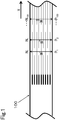
- the partially separated fiber bundle of the present invention has a fiber separating number per unit width A n (units/mm) following the aforementioned relationship, where the fiber separating number A n and so forth is derived as follows. That is, as illustrated in Fig. 1 , the number of fiber bundles contained in the width direction of the partially separated fiber bundle (fiber separating number: N n [units]) measured at a freely selected point P n is divided by a full width of (W n [mm]) of the partially separated fiber bundle, to calculate the fiber separating number per unit width A n (units/mm), and next, the fiber separating number per unit width A n+1 measured at point P n+1 50 cm or more away from the aforementioned freely selected point is calculated.
- n 1 to 100 (where, n is an integer), that is, repeated at 100 points, and the fiber separating number per unit width (A 1 to A 100 ) are individually calculated.
- the lower limit value of ratio A max /A min of the maximum value A max (units/mm) to the minimum value A min (units/mm) is essentially 1.1 or above, preferably 1.3 or above, and more preferably 1.5 or above.
- the upper limit value of ratio A max /A min of the maximum value A max (units/mm) and the minimum value A min (units/mm) is essentially 3 or below, preferably 2.5 or below, and more preferably 2 or below.
- the maximum value A max found from among the fiber separating numbers (A 1 to A 100 ) measured at 100 points in the partially separated fiber bundle, is preferably 4 units/mm or below, more preferably 3.5 units/mm or below, and even more preferably 3 units/mm or below.
- the minimum value of the fiber separating number A min is preferably 0.1 units/mm or above, more preferably 0.3 units/mm or above, and even more preferably 0.5 units/mm or above. With the minimum value of the fiber separating number A min controlled within these ranges, the fiber bundle can be more finely separated, enabling the fiber separation to produce the chopped fibers with more constant width of separated fiber, and the obtainable molded article will have further improved mechanical properties.
- a larger value is basically preferred for each fiber separating number A n . It is therefore preferable that there are 50 or more, out of 100, measured points at which the fiber separating number A n accounts for 80% or more of the maximum value A max , more preferably there are 60 or points, and even more preferably there are 70 or more points. If the number of measurement points, at which the fiber separating number A n accounts for 80% or more of the maximum value A max , is controlled to these ranges, the fiber separation can produce the chopped fibers with more constant width, so that the obtainable molded article with use of the chopped fibers will have further improved mechanical properties, and less variation in mechanical characteristics.
- the number of measurement points, at which the fiber separating number A n accounts for 60% or less of the maximum value A max is preferably 30 or less, out of 100, more preferably 20 or less, and even more preferably 10 or less. If the number of measurement points, at which 60% or less of the maximum value A max is attained, is controlled to these ranges, the fiber separation can produce the chopped fibers with more constant width, so that the obtainable molded article with use of the chopped fibers will have further improved mechanical properties, and less variation in mechanical characteristics.
- the fiber bundle used in the present invention is used as a reinforcing fiber, in which type of the reinforcing fiber is not particularly limited so long as it is a fiber bundle composed of a plurality of single yarns, for which preferred are fibers selected from the group consisting of carbon fiber, glass fiber, aramid fiber and metal fiber. Of these, carbon fiber is preferably used.
- the carbon fiber is not particularly limited, for which polyacrylonitrile (PAN)-based, pitch-based, and rayon-based carbon fibers can be preferably used from the viewpoint of improving mechanical properties and reducing the weight of the fiber reinforced resin. One type of them may be used, or two or more types may be used in a combined manner. Above all, PAN-based carbon fiber is preferably used, from the viewpoint of balance between the strength and elastic modulus of the obtainable fiber-reinforced resin.
- PAN polyacrylonitrile
- Diameter of a single fiber of the reinforcing fiber contained in the reinforcing fiber bundle is preferably 0.5 ⁇ m or larger, more preferably 2 ⁇ m or larger, and even more preferably 4 ⁇ m or larger.
- the diameter of a single fiber of the reinforcing fiber is preferably 20 ⁇ m or smaller, more preferably 15 ⁇ m or smaller, and even more preferably 10 ⁇ m or smaller.
- Strand strength of the reinforcing fiber bundle is preferably 3.0 GPa or larger, more preferably 4.0 GPa or larger, and even more preferably 4.5 GPa or larger.
- Strand elastic modulus of the reinforcing fiber bundle is preferably 200 GPa or larger, more preferably 220 GPa or larger, and even more preferably 240 GPa or larger. With the strand strength or the elastic modulus of the reinforcing fiber bundle individually controlled to these ranges, the mechanical properties of the molded article can be enhanced.
- the carbon fiber is usually sized to yield a fiber bundle containing approximately 3000 to 60,000 single yarns made of continuous fibers, wound on a bobbin, and marketed in the form of wound body (package).
- the fiber bundle used here although preferably untwisted, may be made of twisted strands, in which even those got twisted during transportation may be applicable to the present invention.
- the large tow may alternatively be used in the form of so-called combined yarn in which a plurality of fiber bundles are combined into a single bundle and wound up.
- the partially separated fiber bundle of the present invention preferably has a sizing agent applied thereto.
- Type of solute of the sizing agent is not particularly limited, where applicable compounds include those having a functional group such as epoxy group, urethane group, amino group, carboxy group, etc.
- a sizing agent that contains epoxy resin as a main component, or a sizing agent that contains polyamide resin as a main component is preferably used. They may be used alone or in combination of two or more.
- the reinforcing fiber bundle, to which the sizing agent is already applied, may be further treated with another different type of sizing agent.
- the main component means a component that accounts for 70% by weight or more of the solute component.
- Types of the epoxy resin include bisphenol A type epoxy resin, bisphenol F type epoxy resin, novolac type epoxy resin, aliphatic type epoxy resin, and glycidylamine type epoxy resin, all of which may be used alone, or two more types may be used in a combined manner.
- the polyamide resin preferably used is a water-soluble polyamide resin.
- the water-soluble polyamide may be a polyamide resin obtainable by polycondensing a diamine having a tertiary amino group and/or an oxyethylene group in the principal chain, with a carboxylic acid, in which the diamine useful here includes monomers having a piperazine ring and a tertiary amino group in the principal chain, such as N,N'-bis( ⁇ -aminopropyl)piperazine and N-( ⁇ -aminoethyl)piperazine; and alkyldiamines having an oxyethylene group in the principal chain, such as oxyethylene alkyl amine.
- the dicarboxylic acid usable here includes adipic acid and sebacic acid.
- the sizing agent using the water-soluble polyamide resin excels in affinity with various matrix materials, and remarkably improves physical properties of the composite, in which particularly large effects of improving adhesiveness are demonstrated on matrix materials that contain polyamide-based resin, polyimide-based resin, polyamide-imide-based resin, and polyetheramide-imide resin.
- the water-soluble polyamide may be a copolymer.
- the copolymerization component include lactams such as ⁇ -pyrrolidone, ⁇ -piperidone, ⁇ -caprolactam, ⁇ -methyl- ⁇ -caprolactam, ⁇ -methyl- ⁇ -caprolactam, and ⁇ -laurolactam.
- binary copolymerization or multiple copolymerization is acceptable, in which ratio of copolymerization is determined without interfering physical properties represented by water solubility.
- the ratio of copolymerization of a component having a lactam ring is preferably controlled within the range of 30% by weight or below, otherwise the polymer will not be completely soluble to water.
- organic acid examples include: acetic acid, chloroacetic acid, propionic acid, maleic acid, oxalic acid and fluoroacetic acid; meanwhile examples of the inorganic acid include well-known mineral acid such as hydrochloric acid, sulfuric acid and phosphoric acid.
- Upper limit of the adhesion amount of the sizing agent is preferably 5% by mass or below, assuming the mass of the reinforcing fiber bundle (partially separated fiber bundle to be obtained finally) as 100% by mass, which is more preferably 4% by mass or below, and even more preferably 3% by mass or below.
- the adhesion amount of the sizing agent exceed 5% by mass, the fiber bundle would lose flexibility and become too hard, possibly failing to wind onto, or unwind from the bobbin smoothly. It is also anticipated that the fiber separating device cannot be stuck into the fiber bundle during fiber separation, possibly leaving the unseparated fiber section.
- lower limit of the adhesion amount of the sizing agent is preferably 0.1% by mass or above, more preferably 0.3% by mass or above, and even more preferably 0.5% by mass or above.
- the partially separated fiber bundle according to the present invention is obtained through steps of unwinding the fiber bundle from an unwinding device or the like, widening the fiber bundle as necessary, followed by fiber separation. Each of these steps will be detailed below.
- a fiber bundle composed of a plurality of single yarns is unwound from an unwinding device for unwinding the fiber bundle, or the like, arranged on the upstream side in the travel direction of the fiber bundle.
- Direction of unwinding the fiber bundle is available both in the side-out system in which the fiber bundle is unwound in the direction perpendicular to the rotational axis of bobbin, and in the vertical-out system in which the fiber bundle is unwound in the same direction as the rotational axis of bobbin (paper tube), in which the side-out system is preferred considering that untwisting would be less likely to occur.
- the bobbin during unwinding can be installed in any direction.
- the fiber bundle is preferably held under a certain level of tension.
- the fiber bundle if not kept under a certain tension, would slip off the package (wound article having a bobbin and a fiber bundle wound thereon) and would separate from the package, or the fiber bundle separated from the package would entangle around the rotational axis of the creel, possibly making unwinding difficult.
- a method for fixing the rotational axis of unwinding package other than the method of using the creel, applicable is a surface unwinding system in which the package is placed on, and in parallel to, two rollers which are arranged in parallel, and the package is allowed to roll on the adjacent rollers so as to unwind the fiber bundle.
- the fiber bundle in motion after unwound as described previously is blown with compressed air, or the fiber bundle is allowed to pass through vibrating widening rolls that vibrate in the axial direction, and then through width-limiting rolls, so as to be widened to a desired width.
- a fiber separation blade is intermittently stuck into the widened fiber bundle to partially form a separated fiber section in the reinforcing fiber bundle.
- Fig. 2 illustrates an exemplary process of fiber separation made in the fiber bundle.
- (A) represents a schematic plan view
- (B) represents a schematic front elevation, in which a fiber bundle 100 which is composed of a plurality of single yarns travels from the left (upstream side) to the right (downstream side) of the drawings.
- Fiber bundle travel direction X (arrow) in the drawing represents the longitudinal direction of the fiber bundle 100, indicating that the fiber bundle 100 is continuously fed from an unillustrated fiber bundle feeder.
- the fiber separating device 200 is equipped with a projection 210 (separation blade) having a protruding shape that can be easily stuck into the fiber bundle 100, being designed to stick the projection 210 into the fiber bundle 100 in motion, so as to produce a separated fiber section 150 (in the midst of fiber separation) that extends nearly in parallel to the longitudinal direction of the fiber bundle 100.
- a projection 210 separation blade having a protruding shape that can be easily stuck into the fiber bundle 100, being designed to stick the projection 210 into the fiber bundle 100 in motion, so as to produce a separated fiber section 150 (in the midst of fiber separation) that extends nearly in parallel to the longitudinal direction of the fiber bundle 100.
- Fig. 2 is intended for explaining only action of the projections that are stuck in a phase-matched manner, while omitting other projections that are stuck in a phase-shifted manner.
- the fiber separating device 200 is preferably stuck in the direction along the side surface of the fiber bundle 100.
- the side face of the fiber bundle means a vertical face that appears at the end of a cross section of the fiber bundle (corresponded to the side face of the fiber bundle 100 illustrated in Fig. 1 , for example).
- the fiber separating device 200 has a plurality of projections 210 arranged in the width direction of the fiber bundle 100, and is necessarily driven so as to stick the projections 210 into the fiber bundle in a phase-shifted manner in the fiber bundle travel direction X, in which the number of projections 210 owned by a single fiber separating device 200 is not particularly limited, allowing one, or a plurality of projections 210 per fiber separating device 200. Alternatively, there may be a plurality of fiber separating devices 200 having a single projection 210. In a case where there are a plurality of projections 210 in one fiber separating device 200, each of the projections 210 will have reduced amount of wear per unit time, also making it possible to reduce the frequency of replacement of the fiber separating device.
- Such plurality of fiber separating devices 200 may be arranged in parallel, staggered, or in a phase-shifted manner, so as to freely arrange the plurality of projections 210.
- the plurality of single yarns composing the fiber bundle 100 are not substantially paralleled within the fiber bundle 100, but have a lot of points where the single yarns are interlaced (crossed/entangled).
- an entangled section 160 may be formed during the fiber separation, in the vicinity of a contact part 211 between the fiber bundle 100 and the fiber separating device 200.
- the fiber separating device 200 is removed from the fiber bundle 100. Upon removal, a separated fiber section 110 having gone through the fiber separation is produced, and concurrently, the thus produced entangled section 160 is accumulated at the end part of the separated fiber section 110. Fluff generated from the fiber bundle during the fiber separation will form a fluff accumulation 140.
- the fiber separating device 200 After travel of the fiber bundle over a desired length, the fiber separating device 200 is again stuck into the fiber bundle 100 to leave an unseparated fiber section 130 behind, thus forming a partially separated fiber bundle having the separated fiber section 110 and the unseparated fiber section 130 arranged alternately in the longitudinal direction of the fiber bundle 100, at a certain point in the width direction of the fiber bundle.
- Travel speed of the fiber bundle 100 during the fiber separation is preferably stable with less fluctuation, and more preferably is constant.
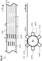
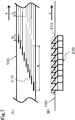
- the fiber separating device 200 is not particularly limited so long as the object of the present invention can be achieved, and is preferably provided with a sharply shaped projection 210 such as metal needle or thin plate. Specifically, preferred is a rotary blade (fiber separating device 200) having a plurality of projections 210 (blades) arranged in a phase-shifted manner in the direction of rotational axis as illustrated in Fig. 4 ; or a fiber separating device 200 having a plurality of vertical blades (projections) to be stuck into the fiber bundle in a phase-shifted manner as illustrated in Figs. 5 to 7 .
- Lower limit of height h of the projection above the surface of the fiber bundle is preferably 5 mm or above, more preferably 7 mm or above, and even more preferably 10 mm or above. Meanwhile, upper limit of the height h of the projection above the surface of the fiber bundle is preferably 50 mm or below, more preferably 35 mm or below, and even more preferably 40 mm or below. With the height h of the projection controlled within these ranges, the fiber separating device can be downsized, and can separate the fiber bundle more stably. Direction of sticking the projections of the fiber separating device into the fiber bundle may be oblique to the fiber bundle, or may be either from the front or the back of the fiber bundle.
- End shape of the projection 210 is preferably as illustrated in Fig. 3 , although not particularly limited so long as it is allowed for sticking. Projections with sharp ends (2a1 to 2a3) have good sticking property, meanwhile projections with rounded ends (2a4 to 2a6) can prevent the single yarn from being broken, causing less fluffing. Projections illustrated in (2a7, 2a8) are particularly improved in sticking property when employed in a rotary fiber separating device.
- the number of projections 210 is preferably (F/10000 - 1) or larger and smaller than (F/50 - 1). With the number controlled smaller than (F/10000 - 1), the mechanical properties will be less likely to improve when the fiber bundle is used to compose a reinforcing fiber composite material in the subsequent process, meanwhile with the value exceeding (F/50 - 1), there will be a risk of yarn breakage or fluffing.
- Separation interval is adjustable on the basis of pitch of the plurality of projections arranged side by side in the width direction of the fiber bundle. By reducing the pitch of the projections and by thus providing a larger number of projections in the width direction of the fiber bundle, the fiber separation will be able to produce a bundle having a less number of single yarns, which is a so-called fine bundle.
- Lower limit of gap between the projections (referred to as width of separated fiber, hereinafter) for forming the fine bundle is preferably 0.1 mm or above, and more preferably 0.2 mm or above. Meanwhile, upper limit for the width of separated fiber is preferably 10 mm or below.
- the fiber separating devices With the width of separated fiber set narrower than 0.1 mm, the fiber separating devices would meander in the travel direction due to fluffs, and the projections would be brought into mutual contact to damage the fiber separating devices. On the other hand, with the width of separated fiber exceeding 10 mm, the fiber separating devices would not be brought into mutual contact, but the travel direction thereof would meander due to fluffing or interlaced single yarns, possibly making it difficult to attain a constant width of separated fiber. Further, the resultant molded article would have reduced demonstration of mechanical properties.
- Figs. 4 and 5 illustrate modes of embodiment, in which positions of the plurality of projections 210 in the fiber separating device are shifted between the upstream side and the downstream side of the fiber bundle 100; and in which two or more projections 210 arranged in the longitudinal direction of the fiber bundle are stuck into the fiber bundle all at once in a single run of the fiber separation.
- Fig. 4 illustrates a rotary blade (fiber separating device 200) having a plurality of projections 210 (blades)
- Fig. 5 illustrates the fiber separating device 200 having a plurality of vertical blades (projections 210).
- Length A (mm) of the separated fiber section ascribed to each projection is preferably 30 mm or longer and 1500 mm or shorter
- distance B (mm) between the adjacent projections on the upstream side and the downstream side is preferably 20 mm or longer and 1500 mm or shorter
- length C (mm) of the unseparated fiber section ascribed to the individual projections is preferably 1 mm or longer and 150 mm or shorter.
- Distance D between loci of fiber separation ascribed to the adjacent projections on the upstream side and the downstream side is preferably 0.01 mm or longer and 5 mm or shorter. Within this range, load on the fiber separating device may be reduced, making it possible to manufacture the partially separated fiber bundle having a relatively uniform fiber separating number in the width direction of the bundle.
- the points of the adjacent projections 210 are differentiated between the upstream side and the downstream side of the fiber bundle 100 as illustrated in Figs. 4 and 5 , it is preferable to adjust ratio of the number of projections arranged on the upstream side and the number of projections arranged on the downstream side (the larger number of arrangement of projections comes in the numerator, and the smaller number of arrangement of projections comes in the denominator) to 1 or larger and 2.5 or smaller, more preferably 1 or larger and 2 or smaller, and even more preferably 1 or larger and 1.5 or smaller.
- the ratio of the number of projections arranged on the upstream side and the number of projections arranged on the downstream side adjusted within these ranges, the width of separated fiber will be made uniform, and the resultant molded article will have small variation in mechanical properties.
- the projections to be arranged on the upstream side and the projections to be arranged on the downstream side are positioned alternately and at the same intervals in the width direction of the fiber bundle.
- Fig. 6 illustrates a mode in which a plurality of projections 210 are arranged in parallel to the width direction of the fiber bundle, and the projections 210 are stuck into and removed from at different timings.
- Difference in the timing of sticking of the adjacent projections into the fiber bundle is preferably 0.2 cycles or larger and 0.8 cycles or smaller, more preferably 0.3 cycles or larger and 0.7 cycles or smaller, and even more preferably 0.4 cycles or larger and 0.6 cycle or smaller.
- one cycle means the time from when the projection is stuck into the fiber bundle, kept stuck for a certain length of time, removed, and then stuck again.
- Length A (mm) of the separated fiber section ascribed to one projection is preferably 30 mm or longer and 1500 mm or shorter, meanwhile length C (mm) of the unseparated fiber section ascribed to one projection is preferably 1 mm or longer and 150 mm or shorter. Within this range, load on the fiber separating device may be reduced, making it possible to manufacture the partially separated fiber bundle that can yield chopped fibers with relatively uniform width of separated fiber.
- Fig. 7 illustrates a mode in which a plurality of projections 210 are serially arranged diagonally to the width direction of the fiber bundle, and the projections 210 are stuck and removed all at once. Similar to Figs. 4 and 5 , two or more projections 210 diagonally arranged in the longitudinal direction of the fiber bundle are simultaneously stuck into the fiber bundle during a single run of fiber separation. Therefore, it becomes possible to manufacture the partially separated fiber bundle that can suppress fluffing, and can yield chopped fibers with relatively uniform width of separated fiber, in the same way as in the modes illustrated in Figs. 4 and 5 .
- Length A (mm) of the separated fiber section ascribed to one projection is preferably 30 mm or longer and 1500 mm or shorter
- distance B (mm) in the longitudinal direction between the adjacent projections on the upstream side and downstream side is preferably 5 mm or longer and 1500 mm or shorter
- length C (mm) of the unseparated fiber section ascribed to one projection is preferably 1 mm or longer and 150 mm or shorter.
- Fig. 9 illustrates an exemplary timing of a sizing agent application step, in the process of manufacturing the reinforcing fiber bundle.
- Fig. 9 illustrates a process of subjecting the fiber bundle 100 to a fiber separation step 300 to yield the partially separated fiber bundle 180, during which a sizing agent application step 400, including a sizing agent coating step 401, a drying step 402, and an heat treating step 403, precedes the fiber separation step 300 as pattern A, and succeeds the fiber separation step 300 as pattern B. Both timings of pattern A and pattern B are acceptable.
- the sizing agent application step does not always necessarily include the drying step and the heat treating step.
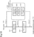
- Fig. 10 illustrates an exemplary timing of the sizing agent application step 400 in the process of manufacturing the reinforcing fiber bundle including a fiber bundle widening step 301.
- Fig. 10 illustrates a process of subjecting the fiber bundle 100 to the fiber bundle widening step 301 and the fiber separation step 300 in this order to yield the partially separated fiber bundle 180, during which a sizing agent application step 400 precedes the fiber bundle widening step 301 as pattern C, is interposed between the fiber bundle widening step 301 and the fiber separation step 300 as pattern D, and succeeds the fiber separation step 300 as pattern E.
- pattern D since the fiber separation may be carried out without causing fluffing, and at high accuracy of width even in narrow-width separation, and since the ratio A max /A min of the maximum value A max (units/mm) and the minimum value A min (units/mm), found from among the fiber separating numbers per unit width (A 1 to A 100 ), becomes controllable.
- the patterns illustrated in this figure does not always necessarily include the drying step and the heat treating step.
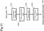
- Fig. 11 illustrates another exemplary timing of the sizing agent coating step, the drying step and the heat treating step, in the process of manufacturing the reinforcing fiber bundle.
- the sizing agent coating step 401, the drying step 402, and the heat treating step 403 in the sizing agent application step are separated, and individually carried at independent timings.
- the sizing agent coating step 401 precedes the fiber separation step 300, and the drying step 402 and the heat treating step 403 succeed the fiber separation step 300.
- Fig. 12 illustrates an exemplary timing of the sizing agent application step that includes the sizing agent coating step, the drying step, and the heat treating step, in the process of manufacturing the reinforcing fiber bundle that includes the fiber bundle widening step, in which in the process of subjecting the fiber bundle 100 to the fiber bundle widening step 301 and the fiber separation step 300 in this order to yield the partially separated fiber bundle 180, the sizing agent coating step 401 of the sizing agent application step precedes the fiber bundle widening step 301; meanwhile the drying step 402 and the heat treating step 403 are interposed between the fiber bundle widening step 301 and the fiber separation step 300 as pattern F, or succeed the fiber separation step 300 as pattern G.
- Fig. 13 illustrates another exemplary timing of the sizing agent application step that includes the sizing agent coating step, the drying step and the heat treating step, in the process of manufacturing the reinforcing fiber bundle that includes the fiber bundle widening step, in which in the process of subjecting the fiber bundle 100 to the fiber bundle widening step 301 and the fiber separation step 300 in this order to yield the partially separated fiber bundle 180, the sizing agent coating step 401 of the sizing agent application step is interposed between the fiber bundle widening step 301 and the fiber separation step 300, and the drying step 402 and the heat treating step 403 succeed the fiber separation step 300.
- the sizing agent can be applied at various timings.
- the measurement was repeated at 100 points, at intervals of 50 cm or longer, in the longitudinal direction of a partially separated fiber bundle.
- the maximum of the fiber separating number per unit width was defined as A max (units/mm), and the minimum of fiber separating number per unit width was defined as A min (units/mm) .
- Continuous operation time is defined as the time ranging from the start of the fiber separation up to when the operation comes to a deadlock due to entanglement of fibers around separation blades or rolls.
- a continuous operation time of one hour or longer was judged as A
- the time of 30 minutes or longer and shorter than one hour was judged as B
- the time of shorter than 30 minutes was judged as C.
- the ratio A max /A min of the maximum value A max (fibers/mm) and the minimum value A min (fibers/mm) found from among the fiber separating numbers per unit width (A 1 to A 100 ) smaller than 2 was judged as A, the ratio of 2 or larger and 3 or smaller was judged as B, and the ratio exceeding 3 was judged as C.
- Averaged value of bending strength of 350 MPa or larger was judged as A, the value 200 MPa or larger and smaller than 350 MPa was judged as B, and the value smaller than 200 MPa was judged as C.
- the coefficient of variation of bending strength of smaller than 10% was judged as A, the value of 10% or larger and smaller than 15% was judged as B, and the value of 15% or larger was judged as C.
- the material fiber was unwound at a constant speed of 10 m/min by using a winder, allowed to pass through vibrating widening rolls that vibrate in the axial direction at 10 Hz for widening, and then allowed to pass through width-limiting rolls, so as to be widened fiber bundle with a desired width.
- the widened fiber bundle was continuously immersed in a sizing agent diluted with purified water.
- the widened fiber bundle coated with the sizing agent was fed to a hot roller at 250°C and a drying oven at 250°C (under air atmosphere) for drying and removing water, and then heat treated for 1.5 minutes.
- the obtained partially separated fiber bundle was confirmed to be separated in the width direction so that fiber bundles have a desired width within the separated fiber section, and to have an entanglement accumulated part in which entangled parts formed of entangled single yarns are accumulated, at one end part or both end parts of at least one separated fiber section.
- the obtained partially separated fiber bundle was then continuously fed to a rotary cutter to cut the fiber bundles, and then cast so as to disperse uniformly, to thereby obtain a discontinuous fiber non-woven fabric in which the fiber orientation is isotropic.
- the discontinuous fiber non-woven fabric was then sandwiched between resin sheets placed on the top and the bottom, and the resin was then allowed to impregnate into the non-woven fabric by using a press machine, to thereby obtain a sheet-like fiber-reinforced thermoplastic resin molding material.
- the fiber separating device in this process was operated so as to repeat a cycle of sticking the vertical blades into the widened fiber bundle that travels at a constant speed of 10 m/min, keeping the vertical blades stuck for 3 seconds to form the separated fiber sections, keeping the vertical blades removed for 0.2 seconds, and then sticking them again. Timings of sticking of the adjacent vertical blades into the fiber bundle were shifted by 0.5 cycles, and height h of the projection above the surface of the fiber bundle was adjusted to 17 mm.
- the obtained partially separated fiber bundle was cut into 13 mm length, and then a fiber-reinforced thermoplastic resin molding material having Resin sheet 1 as the matrix was prepared. The results were as summarized in Table 1.
- a 20-mm-wide widened fiber bundle, with approximately 4% of Sizing agent 1 adhered to Material fiber 2 was separated by using a fiber separating device having 50 vertical blades arranged in two rows (25 blades on the upstream side, and 25 blades on the downstream side) in a staggered manner, and at regular intervals in the width direction of the fiber bundle, as illustrated in Fig. 5 .
- the fiber separating device in this process was operated so as to repeat a cycle of sticking the vertical blades into the widened fiber bundle that travels at a constant speed of 10 m/min, keeping the vertical blades stuck for 3 seconds to form the separated fiber sections, keeping the vertical blades removed for 0.2 seconds, and then sticking them again.
- the fiber separating device in this process was operated so as to repeat a cycle of sticking the projections into the widened fiber bundle that travels at a constant speed of 10 m/min, keeping the projections stuck for 3 seconds to form the separated fiber sections, keeping the projections removed for 0.2 seconds, and then sticking them again.
- a 20-mm-wide widened fiber bundle, with approximately 3.5% of Sizing agent 2 adhered to Material fiber 2 was separated by using a fiber separating device having 25 vertical blades arranged diagonally in line at regular intervals in the width direction of the fiber bundle, while keeping a longitudinal distance B of 5 mm, as illustrated in Fig. 7 .
- the fiber separating device in this process was operated so as to repeat a cycle of sticking the vertical blades into the widened fiber bundle that travels at a constant speed of 10 m/min, keeping the vertical blades stuck for 3 seconds to form the separated fiber sections, keeping the vertical blades removed for 0.2 seconds, and then sticking them again.
- a 20-mm-wide widened fiber bundle, with approximately 3.5% of Sizing agent 2 adhered to Material fiber 2 was separated by using a fiber separating device having 65 vertical blades arranged in line at regular intervals in the width direction of the fiber bundle, as illustrated in Fig. 6 .
- the fiber separating device in this process was operated so as to repeat a cycle of sticking the vertical blades into the widened fiber bundle that travels at a constant speed of 10 m/min, keeping the vertical blades stuck for 3 seconds to form the separated fiber sections, keeping the vertical blades removed for 0.2 seconds, and then sticking them again. Timings of sticking of the adjacent blades into the fiber bundle were shifted by 0.5 cycles, and the height h of the projection above the surface of the fiber bundle was adjusted to 13 mm.
- the obtained partially separated fiber bundle was cut into 13 mm length, and then a fiber-reinforced thermoplastic resin molding material having Resin sheet 2 as the matrix was prepared. The results were as summarized in Table 1.
- the fiber separating device in this process was operated so as to repeat a cycle of sticking the vertical blades into the widened fiber bundle that travels at a constant speed of 10 m/min, keeping the vertical blades stuck for 3 seconds to form the separated fiber sections, keeping the vertical blades removed for 0.2 seconds, and then sticking them again.
- the fiber separating device in this process was operated so as to repeat a cycle of sticking the projections into the widened fiber bundle that travels at a constant speed of 10 m/min, keeping the projections stuck for 3 seconds to form the separated fiber sections, keeping the fiber separating device removed for 0.2 seconds, and then sticking them again.
- a 20-mm-wide widened fiber bundle, with approximately 4% of Sizing agent 1 adhered to Material fiber 2 was separated by using a fiber separating device having 44 vertical blades arranged in two rows (33 blades on the upstream side, and 11 blades on the downstream side) in a staggered manner, and at regular intervals in the width direction of the fiber bundle, as illustrated in Fig. 5 .
- the fiber separating device in this process was operated so as to repeat a cycle of sticking the vertical blades into the widened fiber bundle that travels at a constant speed of 10 m/min, keeping the vertical blades stuck for 3 seconds to form the separated fiber sections, keeping the vertical blades removed for 0.2 seconds, and then sticking them again.
- a 20-mm-wide widened fiber bundle, with approximately 3.5% of Sizing agent 2 adhered to Material fiber 2 was separated by using a fiber separating device having 50 vertical blades arranged in line at regular intervals in the width direction of the fiber bundle, as illustrated in Fig. 6 . All the blades in this process were normally kept stuck into the widened fiber bundle that travels at a constant speed of 10 m/min, with the height h of the projection above the surface of the fiber bundle adjusted to 21 mm.
- the results were as summarized in Table 2, while the separation had to be interrupted due to accumulation of fluffs on the blades that are constantly kept stuck in the bundle and sufficient amount of partially separated fiber bundle for evaluating the physical properties was not obtained.
- the present invention is applicable to any fiber bundle composed of a plurality of single yarns, desired to be separated into a plurality of fine bundles.
- CFRM carbon fiber-sheet molding compound
- a composite that is inexpensive and has mechanical properties, with less variation in the mechanical properties.
Landscapes
- Engineering & Computer Science (AREA)
- Textile Engineering (AREA)
- Chemical & Material Sciences (AREA)
- Chemical Kinetics & Catalysis (AREA)
- Mechanical Engineering (AREA)
- Life Sciences & Earth Sciences (AREA)
- General Life Sciences & Earth Sciences (AREA)
- Geochemistry & Mineralogy (AREA)
- Manufacturing & Machinery (AREA)
- Materials Engineering (AREA)
- Organic Chemistry (AREA)
- Inorganic Chemistry (AREA)
- General Chemical & Material Sciences (AREA)
- Yarns And Mechanical Finishing Of Yarns Or Ropes (AREA)
- Reinforced Plastic Materials (AREA)
- Treatments For Attaching Organic Compounds To Fibrous Goods (AREA)
Abstract
Description
- The present invention relates to a partially separated fiber bundle. More specifically, the present invention relates to a partially separated fiber bundle having a separated fiber section, which can be continuously obtained without causing yarn breakage, from an inexpensive large tow with a large number of single yarns having not been intended for separation.
- There has been known a technology for manufacturing a molded article with a desired shape by thermoforming or pressure molding with use of a molding material composed of a bundle aggregate (also occasionally referred to as fiber bundle, hereinafter) of discontinuous reinforcing fibers (carbon fibers, for example), and a matrix resin. In such technology, a molding material composed of a fiber bundle having a large number of single yarns, although excels in fluidity during molding, tends to demonstrate poor mechanical properties in the form of molded article. On the other hand, a fiber bundle with a freely adjustable number of single yarns has been used, with the aim of balancing between fluidity during molding and mechanical properties of the molded article.
-
Patent Documents 1 and 2, for example, disclose methods for separating a fiber bundle into a freely selectable number of single yarns, by using a multiple fiber bundle wound article having a single bobbin on which a plurality of fiber bundles are preliminarily wound. However, these methods are restricted by the number of single yarns of the fiber bundle in preliminary process, causing limitation of adjustment range and difficulty in adjustment to a desired number of single yarns. - Meanwhile, Patent Documents 3 to 5, for example, disclose methods for longitudinally slitting a fiber bundle into a desired number of single yarns, by using a slitter. These methods, although capable of adjusting the number of single yarns by changing the slit pitch, tends to suffer from difficult handling, since the fiber bundle is longitudinally slit over the entire length in the longitudinal direction, and this raises a need for winding up the thus longitudinally slit fiber bundles individually on separate bobbins, and in a subsequent process a need for unwinding the fiber bundles individually from the plurality of wound bobbins. It is also anticipated that a large amount of fluff generated from the longitudinal slitting entangles around the guide roll, feed roll or the like, when the longitudinally slit fiber bundle is conveyed, making the conveyance difficult.
- Further, Patent Document 6 discloses a method for continuously providing separated fiber sections, by sticking a fiber separating device having a plurality of projections partially into the fiber bundle. The partially separated fiber bundle obtained by the method described in this document, however, tends to cause large variation of width when cut, in a subsequent process, into a certain length to produce chopped fiber, leaving room for improving the mechanical properties of a fiber-reinforced resin molding material and a molded article to be manufactured.
-
- Patent Document 1:
Japanese Patent Laid-open Publication No. 2002-255448 - Patent Document 2:
Japanese Patent Laid-open Publication No. 2004-100132 - Patent Document 3:
Japanese Patent Laid-open Publication No. 2013-49208 - Patent Document 4:
Japanese Patent Laid-open Publication No. 2014-30913 - Patent Document 5:
Japanese Patent No. 5512908 - Patent Document 6:
International Patent Publication No. WO2016/104154 - An object of the present invention is to provide a partially separated fiber bundle which can yield chopped fiber with more uniform width of separated fiber, and capable of composing a fiber-reinforced resin molding material having excellent mechanical properties. Another object is to enable provision of a partially separated fiber bundle continuously over a long time, even from a fiber bundle containing twists, or from a large tow having a large number of single yarns.
- The present invention employs any of the following means in order to solve such problems. That is,
- [1] A partially separated fiber bundle that includes a separated fiber section and an unseparated fiber section, being configured to give a ratio Amax/Amin of 1.1 or larger and 3 or smaller, when the number of fiber bundles contained in the width direction of the partially separated fiber bundle (fiber separating number: Nn [units]), measured at a freely selected point Pn (where, n represents an integer of 1 to 100, and freely selected points Pn and Pn+1, excluding n = 100, being 50 cm or more away from each other), is divided by a full width of Wn [mm] of the partially separated fiber bundle, to calculate the fiber separating number per unit width An (units/mm), and assuming its maximum value as Amax (units/mm) and its minimum value as Amin (units/mm).
- [2] The partially separated fiber bundle according to [1], in which the maximum value Amax is 4 units/mm or smaller.
- [3] The partially separated fiber bundle according to [1] or [2], in which the minimum value Amin is 0.1 units/mm or larger.
- [4] The partially separated fiber bundle according to any one of [1] to [3], in which there are 50 or more, out of 100, measured points Pn at which 80% or more of the maximum value Amax is attained.
- [5] The partially separated fiber bundle according to any one of [1] to [4], in which there are 30 or less, out of 100, measured points Pn at which 60% or less of the maximum value Amax is attained.
- [6] The partially separated fiber bundle according to any one of [1] to [5], in which the fiber bundle is composed of carbon fibers.
- [7] The partially separated fiber bundle according to any one of [1] to [6], in which the fiber bundle contains a sizing agent that contains an epoxy resin as a main component, or a sizing agent that contains a polyamide resin as a main component, an adhesion amounts of the sizing agent being 0.1% by mass or more and 5% by mass or less.
- [8] A method for manufacturing a partially separated fiber bundle, by which a fiber bundle that contains a plurality of single yarns is allowed to travel in the longitudinal direction, and a fiber separating device is intermittently stuck into the fiber bundle, so as to form a separated fiber section and an unseparated fiber section in the fiber bundle, the fiber separating device being stuck at a plurality of points in the width direction of the fiber bundle while being shifted in the longitudinal direction, so as to adjust a ratio Amax/Amin to 1.1 or larger and 3 or smaller, when the number of fiber bundles contained in the width direction of the partially separated fiber bundle (fiber separating number: Nn [units]) measured at a freely selected point Pn (where, n represents an integer of 1 to 100, and freely selected points Pn and Pn+1, excluding n = 100, being 50 cm or more away from each other), is divided by a full width of Wn [mm] of the partially separated fiber bundle, to determine the fiber separating number per unit width An (units/mm), and assuming its maximum value as Amax (units/mm) and its minimum value as Amin (units/mm).
- [9] The method for manufacturing a partially separated fiber bundle according to [8], in which the fiber separating device is stuck at a plurality of points in the width direction of the fiber bundle while being shifted in the longitudinal direction, by using a fiber separating device having a plurality of projections arranged at points corresponding to the plurality of points in the width direction while being shifted in the longitudinal direction, so as to stick the plurality of projections at the same time into the fiber bundle.
- [10] The method for manufacturing a partially separated fiber bundle according to [8] or [9], in which the fiber separating device is stuck at points in the width direction of the fiber bundle, the number of points ranging from (F/10000 - 1) or more up to less than (F/50 - 1), where F is the number of single yarns composing the fiber bundle.
- [11] The method for manufacturing a partially separated fiber bundle according to any one of [8] to [10], further including sizing agent applying step, drying step, heat treating step, and fiber bundle widening step.
- According to the present invention, it becomes possible to provide a partially separated fiber bundle which can yield chopped fiber with more uniform width of separated fiber, and capable of composing a fiber-reinforced resin molding material having excellent mechanical properties. According to the present invention, it also becomes possible to provide a partially separated fiber bundle continuously over a long time, even from a fiber bundle containing twists, or from a large tow having a large number of single yarns.
-
-
Fig. 1 is a schematic view illustrating a method for measuring the fiber separating number in a partially separated fiber bundle according to the present invention. -
Fig. 2 is a diagram illustrating an exemplary process of manufacturing a partially separated fiber bundle by subjecting a fiber bundle to fiber separation, including (A) schematic plan view, and (B) schematic front elevation view. -
Fig. 3 is an explanatory diagram illustrating exemplary shapes of a projection of a fiber separating device. -
Fig. 4 is a schematic view illustrating a rotary fiber separating device having projections in staggered arrangement, stuck into a fiber bundle, including (A) schematic plan view and (B) schematic front elevation view. -
Fig. 5 is a schematic view illustrating a fiber separating device having a plurality of vertical blades in staggered arrangement stuck into a fiber bundle, including (A) schematic plan view, and (B) schematic front elevation view. -
Fig. 6 is a schematic view illustrating use of a fiber separating device having a plurality of vertical blades arranged in line in the width direction of the fiber bundle, with the plurality of vertical blades stuck into the fiber bundle at different timings, including (A) schematic plan view, and (B) schematic front elevation view. -
Fig. 7 is a schematic view illustrating a fiber separating device having a plurality of obliquely arranged vertical blades stuck into a fiber bundle, including (A) schematic plan view, and (B) schematic front elevation view. -
Fig. 8 is a schematic view illustrating use of a rotary fiber separating device having a plurality of projections arranged in line in the width direction of the fiber bundle, with the plurality of projections stuck into the fiber bundle all at once, including (A) schematic plan view, and (B) schematic front elevation view. -
Fig. 9 is a process chart illustrating exemplary timing of a sizing agent application step, in the method for manufacturing a partially separated fiber bundle according to the present invention. -
Fig. 10 is a process chart illustrating exemplary timing of a sizing agent application step that includes a sizing agent coating step and a drying step, in the method for manufacturing a partially separated fiber bundle according to the present invention. -
Fig. 11 is a process chart illustrating another exemplary timing of a sizing agent application step that includes a sizing agent coating step and a drying step, in the method for manufacturing a partially separated fiber bundle according to the present invention. -
Fig. 12 is a process chart illustrating exemplary timing of a sizing agent application step that includes a sizing agent coating step and a drying step, in the method for manufacturing a partially separated fiber bundle including a fiber bundle widening step according to the present invention. -
Fig. 13 is a process chart illustrating another exemplary timing of a sizing agent application step that includes a sizing agent application step and a drying step, in the method for manufacturing a partially separated fiber bundle including a fiber bundle widening step, according to the present invention. - The present invention relates to a partially separated fiber bundle that includes a separated fiber section and an unseparated fiber section, being configured to give a ratio Amax/Amin of 1.1 or larger and 3 or smaller, when the number of fiber bundles contained in the width direction of the partially separated fiber bundle (fiber separating number: Nn [units]), measured at a freely selected point Pn (where, n represents an integer of 1 to 100, and freely selected points Pn and Pn+1, excluding n = 100, being 50 cm or more away from each other), is divided by a full width of Wn [mm] of the partially separated fiber bundle, to calculate the fiber separating number per unit width An (units/mm), and assuming its maximum value as Amax (units/mm) and its minimum value as Amin (units/mm).
- The partially separated fiber bundle of the present invention includes the separated fiber section having slits in the direction of fiber orientation (longitudinal direction) and an unseparated fiber section having no slits, in which in a site of fiber separation, the fiber separation occurs intermittently rather than continuously in the longitudinal direction of the fiber bundle, while leaving the unseparated fiber section on the extension of the slit in the separated fiber section.
- The partially separated fiber bundle of the present invention has a fiber separating number per unit width An (units/mm) following the aforementioned relationship, where the fiber separating number An and so forth is derived as follows. That is, as illustrated in
Fig. 1 , the number of fiber bundles contained in the width direction of the partially separated fiber bundle (fiber separating number: Nn [units]) measured at a freely selected point Pn is divided by a full width of (Wn [mm]) of the partially separated fiber bundle, to calculate the fiber separating number per unit width An (units/mm), and next, the fiber separating number per unit width An+1 measured at point Pn+1 50 cm or more away from the aforementioned freely selected point is calculated. This measurement is repeated over the range of n = 1 to 100 (where, n is an integer), that is, repeated at 100 points, and the fiber separating number per unit width (A1 to A100) are individually calculated. Next, the ratio Amax/Amin of the maximum value Amax (units/mm) and the minimum value Amin (units/mm), found from among the fiber separating number per unit width (A1 to A100) calculated at 100 points, is calculated. - The lower limit value of ratio Amax/Amin of the maximum value Amax (units/mm) to the minimum value Amin (units/mm) is essentially 1.1 or above, preferably 1.3 or above, and more preferably 1.5 or above. With the ratio Amax/Amin of the maximum value Amax (units/mm) and the minimum value Amin (units/mm) controlled to these ranges, the blades will not always be kept stuck in the bundle, making it possible to suppress fluffing, and to elongate replacement intervals of the slitting blades. On the other hand, the upper limit value of ratio Amax/Amin of the maximum value Amax (units/mm) and the minimum value Amin (units/mm) is essentially 3 or below, preferably 2.5 or below, and more preferably 2 or below. With the ratio Amax/Amin of the maximum value Amax (units/mm) and the minimum value Amin (units/mm) controlled to these ranges, the separated fiber sections will be provided more evenly in the longitudinal direction of the fiber bundle, so that an obtainable chopped fiber, cut from the partially separated fiber bundle into a certain length, will have more uniform width of separated fibers, and obtainable molded article will have smaller variation in mechanical properties.
- The maximum value Amax, found from among the fiber separating numbers (A1 to A100) measured at 100 points in the partially separated fiber bundle, is preferably 4 units/mm or below, more preferably 3.5 units/mm or below, and even more preferably 3 units/mm or below. With the maximum value Amax of the fiber separating number to be controlled to this range, the fiber separating device will be easily stuck into the fiber bundle, and the separated fiber sections will be more evenly provided in the fiber bundle, so that the thus obtained partially separated fiber bundle, when made into chopped fibers and contained in the molded article, will be able to further enhance the mechanical properties of the molded article.
- The minimum value of the fiber separating number Amin is preferably 0.1 units/mm or above, more preferably 0.3 units/mm or above, and even more preferably 0.5 units/mm or above. With the minimum value of the fiber separating number Amin controlled within these ranges, the fiber bundle can be more finely separated, enabling the fiber separation to produce the chopped fibers with more constant width of separated fiber, and the obtainable molded article will have further improved mechanical properties.
- From the viewpoint of making the chopped fibers and then obtaining the molded article with high mechanical properties, a larger value is basically preferred for each fiber separating number An. It is therefore preferable that there are 50 or more, out of 100, measured points at which the fiber separating number An accounts for 80% or more of the maximum value Amax, more preferably there are 60 or points, and even more preferably there are 70 or more points. If the number of measurement points, at which the fiber separating number An accounts for 80% or more of the maximum value Amax, is controlled to these ranges, the fiber separation can produce the chopped fibers with more constant width, so that the obtainable molded article with use of the chopped fibers will have further improved mechanical properties, and less variation in mechanical characteristics.
- From the same point of view, the number of measurement points, at which the fiber separating number An accounts for 60% or less of the maximum value Amax, is preferably 30 or less, out of 100, more preferably 20 or less, and even more preferably 10 or less. If the number of measurement points, at which 60% or less of the maximum value Amax is attained, is controlled to these ranges, the fiber separation can produce the chopped fibers with more constant width, so that the obtainable molded article with use of the chopped fibers will have further improved mechanical properties, and less variation in mechanical characteristics.
- The fiber bundle used in the present invention is used as a reinforcing fiber, in which type of the reinforcing fiber is not particularly limited so long as it is a fiber bundle composed of a plurality of single yarns, for which preferred are fibers selected from the group consisting of carbon fiber, glass fiber, aramid fiber and metal fiber. Of these, carbon fiber is preferably used. The carbon fiber is not particularly limited, for which polyacrylonitrile (PAN)-based, pitch-based, and rayon-based carbon fibers can be preferably used from the viewpoint of improving mechanical properties and reducing the weight of the fiber reinforced resin. One type of them may be used, or two or more types may be used in a combined manner. Above all, PAN-based carbon fiber is preferably used, from the viewpoint of balance between the strength and elastic modulus of the obtainable fiber-reinforced resin.
- Diameter of a single fiber of the reinforcing fiber contained in the reinforcing fiber bundle is preferably 0.5 µm or larger, more preferably 2 µm or larger, and even more preferably 4 µm or larger. The diameter of a single fiber of the reinforcing fiber is preferably 20 µm or smaller, more preferably 15 µm or smaller, and even more preferably 10 µm or smaller.
- Strand strength of the reinforcing fiber bundle is preferably 3.0 GPa or larger, more preferably 4.0 GPa or larger, and even more preferably 4.5 GPa or larger. Strand elastic modulus of the reinforcing fiber bundle is preferably 200 GPa or larger, more preferably 220 GPa or larger, and even more preferably 240 GPa or larger. With the strand strength or the elastic modulus of the reinforcing fiber bundle individually controlled to these ranges, the mechanical properties of the molded article can be enhanced.
- The carbon fiber is usually sized to yield a fiber bundle containing approximately 3000 to 60,000 single yarns made of continuous fibers, wound on a bobbin, and marketed in the form of wound body (package). The fiber bundle used here, although preferably untwisted, may be made of twisted strands, in which even those got twisted during transportation may be applicable to the present invention. There is no restriction on the number of single yarns, and use of a so-called large tow, having a large number of single yarns and therefore having a low price per unit weight of fiber bundle, is advantageous since the larger the number of single yarns, the lower the cost of the final product. The large tow may alternatively be used in the form of so-called combined yarn in which a plurality of fiber bundles are combined into a single bundle and wound up.
- The partially separated fiber bundle of the present invention preferably has a sizing agent applied thereto. Type of solute of the sizing agent is not particularly limited, where applicable compounds include those having a functional group such as epoxy group, urethane group, amino group, carboxy group, etc. A sizing agent that contains epoxy resin as a main component, or a sizing agent that contains polyamide resin as a main component is preferably used. They may be used alone or in combination of two or more. The reinforcing fiber bundle, to which the sizing agent is already applied, may be further treated with another different type of sizing agent. Note that the main component means a component that accounts for 70% by weight or more of the solute component.
- Types of the epoxy resin include bisphenol A type epoxy resin, bisphenol F type epoxy resin, novolac type epoxy resin, aliphatic type epoxy resin, and glycidylamine type epoxy resin, all of which may be used alone, or two more types may be used in a combined manner.
- For the polyamide resin, preferably used is a water-soluble polyamide resin. For example, the water-soluble polyamide may be a polyamide resin obtainable by polycondensing a diamine having a tertiary amino group and/or an oxyethylene group in the principal chain, with a carboxylic acid, in which the diamine useful here includes monomers having a piperazine ring and a tertiary amino group in the principal chain, such as N,N'-bis(γ-aminopropyl)piperazine and N-(β-aminoethyl)piperazine; and alkyldiamines having an oxyethylene group in the principal chain, such as oxyethylene alkyl amine. The dicarboxylic acid usable here includes adipic acid and sebacic acid.
- The sizing agent using the water-soluble polyamide resin excels in affinity with various matrix materials, and remarkably improves physical properties of the composite, in which particularly large effects of improving adhesiveness are demonstrated on matrix materials that contain polyamide-based resin, polyimide-based resin, polyamide-imide-based resin, and polyetheramide-imide resin.
- The water-soluble polyamide may be a copolymer. Examples of the copolymerization component include lactams such as α-pyrrolidone, α-piperidone, ε-caprolactam, α-methyl-ε-caprolactam, ε-methyl-ε-caprolactam, and ε-laurolactam. Also binary copolymerization or multiple copolymerization is acceptable, in which ratio of copolymerization is determined without interfering physical properties represented by water solubility. The ratio of copolymerization of a component having a lactam ring is preferably controlled within the range of 30% by weight or below, otherwise the polymer will not be completely soluble to water.
- Even poorly water-soluble polymers having the ratio of copolymerization of a component out of the aforementioned range may, however, have increased solubility and may become water soluble, if the solution is acidified with use of an organic or inorganic acid. Examples of the organic acid include: acetic acid, chloroacetic acid, propionic acid, maleic acid, oxalic acid and fluoroacetic acid; meanwhile examples of the inorganic acid include well-known mineral acid such as hydrochloric acid, sulfuric acid and phosphoric acid.
- Upper limit of the adhesion amount of the sizing agent is preferably 5% by mass or below, assuming the mass of the reinforcing fiber bundle (partially separated fiber bundle to be obtained finally) as 100% by mass, which is more preferably 4% by mass or below, and even more preferably 3% by mass or below. With the adhesion amount of the sizing agent exceeding 5% by mass, the fiber bundle would lose flexibility and become too hard, possibly failing to wind onto, or unwind from the bobbin smoothly. It is also anticipated that the fiber separating device cannot be stuck into the fiber bundle during fiber separation, possibly leaving the unseparated fiber section.
- Meanwhile, lower limit of the adhesion amount of the sizing agent is preferably 0.1% by mass or above, more preferably 0.3% by mass or above, and even more preferably 0.5% by mass or above. With the adhesion amount of the sizing agent controlled within these ranges, obtainable is an effect of suppressing interlaced part where the single yarns are interlaced, advantageously improving productivity and quality of the partially separated fiber bundle. Moreover, the fiber bundle, when cut, may be suppressed from being split or unsized into single yarns, thus improving retainability of a predetermined bundle form. That is, it becomes possible to narrow distribution of the number of single yarns that compose the chopped fiber bundle, and to obtain a uniform and optimally-shaped chopped fiber bundle. This makes it possible to improve the mechanical properties of the molded article, and to reduce variation in the mechanical properties. How to derive the adhesion amount of the sizing agent will be described later.
- Next, a method for manufacturing a partially separated fiber bundle according to the present invention will be specifically explained, with reference to examples. Note that the partially separated fiber bundle according to the present invention is not construed as being limited to the specific aspects disclosed below.
- The partially separated fiber bundle according to the present invention is obtained through steps of unwinding the fiber bundle from an unwinding device or the like, widening the fiber bundle as necessary, followed by fiber separation. Each of these steps will be detailed below.
- First, unwinding of the fiber bundle will be explained. A fiber bundle composed of a plurality of single yarns is unwound from an unwinding device for unwinding the fiber bundle, or the like, arranged on the upstream side in the travel direction of the fiber bundle. Direction of unwinding the fiber bundle is available both in the side-out system in which the fiber bundle is unwound in the direction perpendicular to the rotational axis of bobbin, and in the vertical-out system in which the fiber bundle is unwound in the same direction as the rotational axis of bobbin (paper tube), in which the side-out system is preferred considering that untwisting would be less likely to occur.
- The bobbin during unwinding can be installed in any direction. Above all, in a case where the bobbin is stuck on a creel, with an end face of the bobbin, opposite to the end face fixed to the rotational axis of creel, oriented to any direction but not horizontally, the fiber bundle is preferably held under a certain level of tension. The fiber bundle, if not kept under a certain tension, would slip off the package (wound article having a bobbin and a fiber bundle wound thereon) and would separate from the package, or the fiber bundle separated from the package would entangle around the rotational axis of the creel, possibly making unwinding difficult.
- As a method for fixing the rotational axis of unwinding package, other than the method of using the creel, applicable is a surface unwinding system in which the package is placed on, and in parallel to, two rollers which are arranged in parallel, and the package is allowed to roll on the adjacent rollers so as to unwind the fiber bundle.
- In a case of unwinding with use of a creel, another possible method is to hang a belt on the creel, with one end fixed, and with the other end pulled by hanging a weight or with a spring so as to brake the creel, thus applying tension to the fiber bundle to be unwound. In this case, varying the braking force depending on the diameter of winding will provide an effective means for stabilizing the tension.
- Next, the steps of widening and fiber separation will be explained. Note that the processes below are not always necessarily carried out under constant conditions, instead allowing variation of width of winding at a certain periodicity or at a desired point.
- In the widening step for example, the fiber bundle in motion after unwound as described previously is blown with compressed air, or the fiber bundle is allowed to pass through vibrating widening rolls that vibrate in the axial direction, and then through width-limiting rolls, so as to be widened to a desired width.
- In the fiber separation process, a fiber separation blade is intermittently stuck into the widened fiber bundle to partially form a separated fiber section in the reinforcing fiber bundle.
Fig. 2 illustrates an exemplary process of fiber separation made in the fiber bundle. (A) represents a schematic plan view, and (B) represents a schematic front elevation, in which afiber bundle 100 which is composed of a plurality of single yarns travels from the left (upstream side) to the right (downstream side) of the drawings. Fiber bundle travel direction X (arrow) in the drawing represents the longitudinal direction of thefiber bundle 100, indicating that thefiber bundle 100 is continuously fed from an unillustrated fiber bundle feeder. - The
fiber separating device 200 is equipped with a projection 210 (separation blade) having a protruding shape that can be easily stuck into thefiber bundle 100, being designed to stick theprojection 210 into thefiber bundle 100 in motion, so as to produce a separated fiber section 150 (in the midst of fiber separation) that extends nearly in parallel to the longitudinal direction of thefiber bundle 100. Note now, although in the present invention, the projections of the fiber separating device, which are to be stuck at a plurality of points in the width direction of the fiber bundle, need be stuck in a phase-shifted manner in the longitudinal direction of the fiber bundle, -
Fig. 2 is intended for explaining only action of the projections that are stuck in a phase-matched manner, while omitting other projections that are stuck in a phase-shifted manner. - Now as illustrated in
Fig. 2(B) , thefiber separating device 200 is preferably stuck in the direction along the side surface of thefiber bundle 100. Assuming the cross section of the fiber bundle has a flat shape such as horizontal ellipse or horizontally long rectangle, the side face of the fiber bundle means a vertical face that appears at the end of a cross section of the fiber bundle (corresponded to the side face of thefiber bundle 100 illustrated inFig. 1 , for example). - The
fiber separating device 200 has a plurality ofprojections 210 arranged in the width direction of thefiber bundle 100, and is necessarily driven so as to stick theprojections 210 into the fiber bundle in a phase-shifted manner in the fiber bundle travel direction X, in which the number ofprojections 210 owned by a singlefiber separating device 200 is not particularly limited, allowing one, or a plurality ofprojections 210 perfiber separating device 200. Alternatively, there may be a plurality offiber separating devices 200 having asingle projection 210. In a case where there are a plurality ofprojections 210 in onefiber separating device 200, each of theprojections 210 will have reduced amount of wear per unit time, also making it possible to reduce the frequency of replacement of the fiber separating device. It is also acceptable to use a plurality offiber separating devices 200 at the same time, depending on the number of fiber bundles to be separated. Such plurality offiber separating devices 200 may be arranged in parallel, staggered, or in a phase-shifted manner, so as to freely arrange the plurality ofprojections 210. - The plurality of single yarns composing the
fiber bundle 100 are not substantially paralleled within thefiber bundle 100, but have a lot of points where the single yarns are interlaced (crossed/entangled). Hence, when separating thefiber bundle 100 composed of a plurality of single yarns into fiber bundles with less number of yarns by using thefiber separating device 200, anentangled section 160 may be formed during the fiber separation, in the vicinity of acontact part 211 between thefiber bundle 100 and thefiber separating device 200. Here, the notation "anentangled section 160 may be formed" exemplifies a case where entanglement among the single yarns, having been resided within a range of fiber separation, is formed (moved) into thecontact part 211 by thefiber separating device 200, or a case where a new aggregate of interlaced single yarns is formed (created) by thefiber separating device 200. - After forming the separated
fiber section 150 over a freely selectable range, thefiber separating device 200 is removed from thefiber bundle 100. Upon removal, a separatedfiber section 110 having gone through the fiber separation is produced, and concurrently, the thus producedentangled section 160 is accumulated at the end part of the separatedfiber section 110. Fluff generated from the fiber bundle during the fiber separation will form afluff accumulation 140. - After travel of the fiber bundle over a desired length, the
fiber separating device 200 is again stuck into thefiber bundle 100 to leave anunseparated fiber section 130 behind, thus forming a partially separated fiber bundle having the separatedfiber section 110 and theunseparated fiber section 130 arranged alternately in the longitudinal direction of thefiber bundle 100, at a certain point in the width direction of the fiber bundle. - Travel speed of the
fiber bundle 100 during the fiber separation is preferably stable with less fluctuation, and more preferably is constant. - Although not illustrated in
Fig. 2 , when sticking the plurality of projections in the width direction of the fiber bundle in the aforementioned fiber separation of the present invention, such plurality of projections are stuck into the fiber bundle in a phase-shifted manner in the longitudinal direction. - The
fiber separating device 200 is not particularly limited so long as the object of the present invention can be achieved, and is preferably provided with a sharply shapedprojection 210 such as metal needle or thin plate. Specifically, preferred is a rotary blade (fiber separating device 200) having a plurality of projections 210 (blades) arranged in a phase-shifted manner in the direction of rotational axis as illustrated inFig. 4 ; or afiber separating device 200 having a plurality of vertical blades (projections) to be stuck into the fiber bundle in a phase-shifted manner as illustrated inFigs. 5 to 7 . - Lower limit of height h of the projection above the surface of the fiber bundle is preferably 5 mm or above, more preferably 7 mm or above, and even more preferably 10 mm or above. Meanwhile, upper limit of the height h of the projection above the surface of the fiber bundle is preferably 50 mm or below, more preferably 35 mm or below, and even more preferably 40 mm or below. With the height h of the projection controlled within these ranges, the fiber separating device can be downsized, and can separate the fiber bundle more stably. Direction of sticking the projections of the fiber separating device into the fiber bundle may be oblique to the fiber bundle, or may be either from the front or the back of the fiber bundle.
- End shape of the
projection 210 is preferably as illustrated inFig. 3 , although not particularly limited so long as it is allowed for sticking. Projections with sharp ends (2a1 to 2a3) have good sticking property, meanwhile projections with rounded ends (2a4 to 2a6) can prevent the single yarn from being broken, causing less fluffing. Projections illustrated in (2a7, 2a8) are particularly improved in sticking property when employed in a rotary fiber separating device. - There are required a plurality of
projections 210 arranged in the width direction of thefiber bundle 100 to be separated, in which the number thereof is freely selectable depending on the number of single yarns F (fibers) that compose thefiber bundle 100 to be separated. The number ofprojections 210, in the width direction of thefiber bundle 100, is preferably (F/10000 - 1) or larger and smaller than (F/50 - 1). With the number controlled smaller than (F/10000 - 1), the mechanical properties will be less likely to improve when the fiber bundle is used to compose a reinforcing fiber composite material in the subsequent process, meanwhile with the value exceeding (F/50 - 1), there will be a risk of yarn breakage or fluffing. - Separation interval is adjustable on the basis of pitch of the plurality of projections arranged side by side in the width direction of the fiber bundle. By reducing the pitch of the projections and by thus providing a larger number of projections in the width direction of the fiber bundle, the fiber separation will be able to produce a bundle having a less number of single yarns, which is a so-called fine bundle. Lower limit of gap between the projections (referred to as width of separated fiber, hereinafter) for forming the fine bundle is preferably 0.1 mm or above, and more preferably 0.2 mm or above. Meanwhile, upper limit for the width of separated fiber is preferably 10 mm or below. With the width of separated fiber set narrower than 0.1 mm, the fiber separating devices would meander in the travel direction due to fluffs, and the projections would be brought into mutual contact to damage the fiber separating devices. On the other hand, with the width of separated fiber exceeding 10 mm, the fiber separating devices would not be brought into mutual contact, but the travel direction thereof would meander due to fluffing or interlaced single yarns, possibly making it difficult to attain a constant width of separated fiber. Further, the resultant molded article would have reduced demonstration of mechanical properties.
- Next, the fiber separating device having a plurality of projections will be explained with reference to
Figs. 4 to 7 . -
Figs. 4 and5 illustrate modes of embodiment, in which positions of the plurality ofprojections 210 in the fiber separating device are shifted between the upstream side and the downstream side of thefiber bundle 100; and in which two ormore projections 210 arranged in the longitudinal direction of the fiber bundle are stuck into the fiber bundle all at once in a single run of the fiber separation.Fig. 4 illustrates a rotary blade (fiber separating device 200) having a plurality of projections 210 (blades), andFig. 5 illustrates thefiber separating device 200 having a plurality of vertical blades (projections 210). By thus arranging the projections in a staggered manner, that is, by arranging the projections at points corresponding to a plurality of points in the width direction of the fiber bundle while shifting them in the longitudinal direction, it now becomes possible to stick the plurality of projections into the fiber bundle all at once, and consequently to manufacture the partially separated fiber bundle which is suppressed in fluffing, and to yield chopped fibers with a relatively uniform width of separated fiber. The plurality of projections to be stuck into the fiber bundle in this situation may only be shifted in the longitudinal direction, so that such plurality of projections are not always necessarily arranged on a single fiber separating device. - Length A (mm) of the separated fiber section ascribed to each projection is preferably 30 mm or longer and 1500 mm or shorter, distance B (mm) between the adjacent projections on the upstream side and the downstream side is preferably 20 mm or longer and 1500 mm or shorter, and length C (mm) of the unseparated fiber section ascribed to the individual projections is preferably 1 mm or longer and 150 mm or shorter. Distance D between loci of fiber separation ascribed to the adjacent projections on the upstream side and the downstream side is preferably 0.01 mm or longer and 5 mm or shorter. Within this range, load on the fiber separating device may be reduced, making it possible to manufacture the partially separated fiber bundle having a relatively uniform fiber separating number in the width direction of the bundle.
- In a case where the points of the
adjacent projections 210 are differentiated between the upstream side and the downstream side of thefiber bundle 100 as illustrated inFigs. 4 and5 , it is preferable to adjust ratio of the number of projections arranged on the upstream side and the number of projections arranged on the downstream side (the larger number of arrangement of projections comes in the numerator, and the smaller number of arrangement of projections comes in the denominator) to 1 or larger and 2.5 or smaller, more preferably 1 or larger and 2 or smaller, and even more preferably 1 or larger and 1.5 or smaller. With the ratio of the number of projections arranged on the upstream side and the number of projections arranged on the downstream side adjusted within these ranges, the width of separated fiber will be made uniform, and the resultant molded article will have small variation in mechanical properties. - When arranging the points of the adjacent projections while being differentiated between the upstream side and the downstream side of the fiber bundle, it is preferable that there is at least one point where the arrangement interval of the projections in the direction orthogonal to the longitudinal direction of the fiber bundle, the projections being arranged on the upstream side of the fiber bundle, and the arrangement interval of the projections in the direction orthogonal to the longitudinal direction of the fiber bundle, the projections being arranged on the downstream side of the fiber bundle, become identical; and that the projections to be arranged on the upstream side and the projections to be arranged on the downstream side are positioned alternately and at the same intervals in the width direction of the fiber bundle.
-
Fig. 6 illustrates a mode in which a plurality ofprojections 210 are arranged in parallel to the width direction of the fiber bundle, and theprojections 210 are stuck into and removed from at different timings. Difference in the timing of sticking of the adjacent projections into the fiber bundle is preferably 0.2 cycles or larger and 0.8 cycles or smaller, more preferably 0.3 cycles or larger and 0.7 cycles or smaller, and even more preferably 0.4 cycles or larger and 0.6 cycle or smaller. With the sticking and removal controlled within these ranges, it becomes possible to manufacture the partially separated fiber bundle that can suppress fluffing, and can yield chopped fibers with relatively uniform width of separated fiber. Now, one cycle means the time from when the projection is stuck into the fiber bundle, kept stuck for a certain length of time, removed, and then stuck again. Length A (mm) of the separated fiber section ascribed to one projection is preferably 30 mm or longer and 1500 mm or shorter, meanwhile length C (mm) of the unseparated fiber section ascribed to one projection is preferably 1 mm or longer and 150 mm or shorter. Within this range, load on the fiber separating device may be reduced, making it possible to manufacture the partially separated fiber bundle that can yield chopped fibers with relatively uniform width of separated fiber. - In the cases illustrated in
Figs. 4 to 6 , it is also preferable to control the timing of sticking and removing the projections of the fiber separating device, so that there will be no section in which unseparated fiber sections appear over the entire width of the fiber bundle. Such control makes it possible to manufacture the partially separated fiber bundle in which the width of each of the separated fiber bundles is relatively uniform. -
Fig. 7 illustrates a mode in which a plurality ofprojections 210 are serially arranged diagonally to the width direction of the fiber bundle, and theprojections 210 are stuck and removed all at once. Similar toFigs. 4 and5 , two ormore projections 210 diagonally arranged in the longitudinal direction of the fiber bundle are simultaneously stuck into the fiber bundle during a single run of fiber separation. Therefore, it becomes possible to manufacture the partially separated fiber bundle that can suppress fluffing, and can yield chopped fibers with relatively uniform width of separated fiber, in the same way as in the modes illustrated inFigs. 4 and5 . - Length A (mm) of the separated fiber section ascribed to one projection is preferably 30 mm or longer and 1500 mm or shorter, distance B (mm) in the longitudinal direction between the adjacent projections on the upstream side and downstream side is preferably 5 mm or longer and 1500 mm or shorter, and length C (mm) of the unseparated fiber section ascribed to one projection is preferably 1 mm or longer and 150 mm or shorter. Within this range, load on the fiber separating device may be reduced, making it possible to manufacture the partially separated fiber bundle that can yield chopped fibers with relatively uniform width of separated fiber.
- The thus obtained partially separated fiber bundle preferably has a sizing agent applied thereto. Next, timing of applying the sizing agent will be explained with reference to
Figs. 9 to 13 .Fig. 9 illustrates an exemplary timing of a sizing agent application step, in the process of manufacturing the reinforcing fiber bundle.Fig. 9 illustrates a process of subjecting thefiber bundle 100 to afiber separation step 300 to yield the partially separatedfiber bundle 180, during which a sizingagent application step 400, including a sizingagent coating step 401, a dryingstep 402, and anheat treating step 403, precedes thefiber separation step 300 as pattern A, and succeeds thefiber separation step 300 as pattern B. Both timings of pattern A and pattern B are acceptable. Note that the sizing agent application step does not always necessarily include the drying step and the heat treating step. -
Fig. 10 illustrates an exemplary timing of the sizingagent application step 400 in the process of manufacturing the reinforcing fiber bundle including a fiberbundle widening step 301.Fig. 10 illustrates a process of subjecting thefiber bundle 100 to the fiberbundle widening step 301 and thefiber separation step 300 in this order to yield the partially separatedfiber bundle 180, during which a sizingagent application step 400 precedes the fiberbundle widening step 301 as pattern C, is interposed between the fiberbundle widening step 301 and thefiber separation step 300 as pattern D, and succeeds thefiber separation step 300 as pattern E. Among the timings of pattern C, pattern D and pattern E, although all being acceptable, most preferred is pattern D, since the fiber separation may be carried out without causing fluffing, and at high accuracy of width even in narrow-width separation, and since the ratio Amax/Amin of the maximum value Amax (units/mm) and the minimum value Amin (units/mm), found from among the fiber separating numbers per unit width (A1 to A100), becomes controllable. Note also the patterns illustrated in this figure does not always necessarily include the drying step and the heat treating step. -
Fig. 11 illustrates another exemplary timing of the sizing agent coating step, the drying step and the heat treating step, in the process of manufacturing the reinforcing fiber bundle. In the exemplary timing illustrated inFig. 11 , the sizingagent coating step 401, the dryingstep 402, and theheat treating step 403 in the sizing agent application step are separated, and individually carried at independent timings. The sizingagent coating step 401 precedes thefiber separation step 300, and the dryingstep 402 and theheat treating step 403 succeed thefiber separation step 300. -
Fig. 12 illustrates an exemplary timing of the sizing agent application step that includes the sizing agent coating step, the drying step, and the heat treating step, in the process of manufacturing the reinforcing fiber bundle that includes the fiber bundle widening step, in which in the process of subjecting thefiber bundle 100 to the fiberbundle widening step 301 and thefiber separation step 300 in this order to yield the partially separatedfiber bundle 180, the sizingagent coating step 401 of the sizing agent application step precedes the fiberbundle widening step 301; meanwhile the dryingstep 402 and theheat treating step 403 are interposed between the fiberbundle widening step 301 and thefiber separation step 300 as pattern F, or succeed thefiber separation step 300 as pattern G. -
Fig. 13 illustrates another exemplary timing of the sizing agent application step that includes the sizing agent coating step, the drying step and the heat treating step, in the process of manufacturing the reinforcing fiber bundle that includes the fiber bundle widening step, in which in the process of subjecting thefiber bundle 100 to the fiberbundle widening step 301 and thefiber separation step 300 in this order to yield the partially separatedfiber bundle 180, the sizingagent coating step 401 of the sizing agent application step is interposed between the fiberbundle widening step 301 and thefiber separation step 300, and the dryingstep 402 and theheat treating step 403 succeed thefiber separation step 300. - As described above, in the method for manufacturing a partially separated fiber bundle of the present invention, the sizing agent can be applied at various timings.
- The present invention will be detailed below, referring to Examples. Various measurement methods, calculation methods and evaluation methods are as follows.
- As illustrated in
Fig. 1 , at freely selectable points Pn (n = 1 to 100) of the fiber bundle, measured were full width Wn (n = 1 to 100) (mm) of the fiber bundle that ranges from end to end, and the number of fiber bundles Nn (n = 1 to 100) (units) that form the fiber bundle having a width of 0.1 mm or larger. The measurement was repeated at 100 points, at intervals of 50 cm or longer, in the longitudinal direction of a partially separated fiber bundle. The number Nn of fiber bundles having a bundle width of 0.1 mm or more, was divided by the full width Wn of the fiber bundles, to determine the fiber separating number per unit width Nn/Wn = An (units/mm) . Among 100 points, the maximum of the fiber separating number per unit width was defined as Amax (units/mm), and the minimum of fiber separating number per unit width was defined as Amin (units/mm) . - Approximately 5 g of a carbon fiber bundle with a sizing agent adhered thereto was sampled, and was put in a heat-resistant vessel. The vessel was then dried at 80°C in vacuo for 24 hours, cooled down to room temperature with care so as to avoid moisture absorption, the carbon fiber was weighed to find mass m1 (g), and then ashed together with the vessel in a nitrogen atmosphere at 500°C for 15 minutes. The sample was then cooled down to room temperature with care so as to avoid moisture absorption, and the carbon fiber was weighed to find mass m2 (g). After the processes, the adhesion amount of sizing agent adhered to the carbon fiber was determined by the equation below. The measurement was repeated for each of 10 fiber bundles, and an average value was calculated.

- Continuous operation time is defined as the time ranging from the start of the fiber separation up to when the operation comes to a deadlock due to entanglement of fibers around separation blades or rolls. A continuous operation time of one hour or longer was judged as A, the time of 30 minutes or longer and shorter than one hour was judged as B, and the time of shorter than 30 minutes was judged as C.
- The ratio Amax/Amin of the maximum value Amax (fibers/mm) and the minimum value Amin (fibers/mm) found from among the fiber separating numbers per unit width (A1 to A100) smaller than 2 was judged as A, the ratio of 2 or larger and 3 or smaller was judged as B, and the ratio exceeding 3 was judged as C.
- A fiber-reinforced resin molding material was subjected to the method described later, to obtain a flat plate molded article having a size of 300 × 300 mm. Assuming the longitudinal direction of the flat plate as 0°, sixteen test pieces, each piece being 100 × 25 × 2 mm, were cut out from the obtained flat plate in 0° direction and 90° direction (32 pieces in total). The pieces are then subjected to measurement in accordance with JIS K 7074 (1988) to find average value, standard deviation, and coefficient of variation (= standard deviation/average value × 100) of bending strength. Averaged value of bending strength of 350 MPa or larger was judged as A, the
value 200 MPa or larger and smaller than 350 MPa was judged as B, and the value smaller than 200 MPa was judged as C. The coefficient of variation of bending strength of smaller than 10% was judged as A, the value of 10% or larger and smaller than 15% was judged as B, and the value of 15% or larger was judged as C. -
- Material fiber 1: Carbon fiber bundle ("PX35" from ZOLTEK Corporation, 50,000 single yarns, with "13" sizing agent) was used.
- Material fiber 2: Carbon fiber bundle ("T700SC-24K-50C" from Toray Industries, Inc., 24,000 single yarns) was used.
- Resin sheet 1: A sheet was prepared using a polyamide masterbatch made of polyamide 6 resin ("Amilan" (registered trademark) CM1001 from Toray Industries, Inc.).
- Resin sheet 2: A sheet was prepared using a polypropylene masterbatch composed of 90% by mass of unmodified polypropylene resin ("Prime Polypro" (registered trademark) J106MG from Prime Polymer Co., Ltd.), and 10% by mass of an acid-modified polypropylene resin ("Admer" (registered trademark) QE800, from Mitsui Chemicals, Inc.).
- Sizing agent 1: Water-soluble polyamide ("T-70" from Toray Industries, Inc.) was used.
- Sizing agent 2: Water-soluble polyamide ("A-90" from Toray Industries, Inc.) was used.
- The material fiber was unwound at a constant speed of 10 m/min by using a winder, allowed to pass through vibrating widening rolls that vibrate in the axial direction at 10 Hz for widening, and then allowed to pass through width-limiting rolls, so as to be widened fiber bundle with a desired width.
- Then, the widened fiber bundle was continuously immersed in a sizing agent diluted with purified water. Next, the widened fiber bundle coated with the sizing agent was fed to a hot roller at 250°C and a drying oven at 250°C (under air atmosphere) for drying and removing water, and then heat treated for 1.5 minutes.
- The obtained partially separated fiber bundle was confirmed to be separated in the width direction so that fiber bundles have a desired width within the separated fiber section, and to have an entanglement accumulated part in which entangled parts formed of entangled single yarns are accumulated, at one end part or both end parts of at least one separated fiber section.
- The obtained partially separated fiber bundle was then continuously fed to a rotary cutter to cut the fiber bundles, and then cast so as to disperse uniformly, to thereby obtain a discontinuous fiber non-woven fabric in which the fiber orientation is isotropic.
- The discontinuous fiber non-woven fabric was then sandwiched between resin sheets placed on the top and the bottom, and the resin was then allowed to impregnate into the non-woven fabric by using a press machine, to thereby obtain a sheet-like fiber-reinforced thermoplastic resin molding material.
- A 40-mm-wide widened fiber bundle, with approximately 4% of Sizing
agent 2 adhered to Material fiber 1, was separated by using a fiber separating device having 50 vertical blades arranged in line at regular intervals in the width direction of the fiber bundle, as illustrated inFig. 6 . The fiber separating device in this process was operated so as to repeat a cycle of sticking the vertical blades into the widened fiber bundle that travels at a constant speed of 10 m/min, keeping the vertical blades stuck for 3 seconds to form the separated fiber sections, keeping the vertical blades removed for 0.2 seconds, and then sticking them again. Timings of sticking of the adjacent vertical blades into the fiber bundle were shifted by 0.5 cycles, and height h of the projection above the surface of the fiber bundle was adjusted to 17 mm. The obtained partially separated fiber bundle was cut into 13 mm length, and then a fiber-reinforced thermoplastic resin molding material having Resin sheet 1 as the matrix was prepared. The results were as summarized in Table 1. - A 20-mm-wide widened fiber bundle, with approximately 4% of Sizing agent 1 adhered to
Material fiber 2, was separated by using a fiber separating device having 50 vertical blades arranged in two rows (25 blades on the upstream side, and 25 blades on the downstream side) in a staggered manner, and at regular intervals in the width direction of the fiber bundle, as illustrated inFig. 5 . The fiber separating device in this process was operated so as to repeat a cycle of sticking the vertical blades into the widened fiber bundle that travels at a constant speed of 10 m/min, keeping the vertical blades stuck for 3 seconds to form the separated fiber sections, keeping the vertical blades removed for 0.2 seconds, and then sticking them again. Distance B between the adjacent vertical blades in the longitudinal direction of the fiber bundle was adjusted to 15 mm, timing of sticking of all blades into the fiber bundle was set to be synchronized, and height h of the projection above the surface of the fiber bundle was adjusted to 17 mm. The obtained partially separated fiber bundle was cut into 13 mm length, and then a fiber-reinforced thermoplastic resin molding material havingResin sheet 2 as the matrix was prepared. The results were as summarized in Table 1. - A 20-mm-wide widened fiber bundle, with approximately 4% of Sizing agent 1 adhered to
Material fiber 2, was separated by using a rotary blade (fiber separating device) having 25 projections (blades) arranged in two rows in total in a staggered manner, and at regular intervals in the width direction of the fiber bundle, as illustrated inFig. 4 . The fiber separating device in this process was operated so as to repeat a cycle of sticking the projections into the widened fiber bundle that travels at a constant speed of 10 m/min, keeping the projections stuck for 3 seconds to form the separated fiber sections, keeping the projections removed for 0.2 seconds, and then sticking them again. Distance B between the adjacent projections in the longitudinal direction of the fiber bundle was adjusted to 15 mm, timing of sticking of all projections (50 projections in total) into the fiber bundle was set to be synchronized, and height h of the projection above the surface of the fiber bundle was adjusted to 4 mm. The obtained partially separated fiber bundle was cut into 13 mm length, and then a fiber-reinforced thermoplastic resin molding material havingResin sheet 2 as the matrix was prepared. The results were as summarized in Table 1. - A 20-mm-wide widened fiber bundle, with approximately 3.5% of Sizing
agent 2 adhered toMaterial fiber 2, was separated by using a fiber separating device having 25 vertical blades arranged diagonally in line at regular intervals in the width direction of the fiber bundle, while keeping a longitudinal distance B of 5 mm, as illustrated inFig. 7 . The fiber separating device in this process was operated so as to repeat a cycle of sticking the vertical blades into the widened fiber bundle that travels at a constant speed of 10 m/min, keeping the vertical blades stuck for 3 seconds to form the separated fiber sections, keeping the vertical blades removed for 0.2 seconds, and then sticking them again. Timing of sticking of all blades into the fiber bundle was set to be synchronized, and the height h of the projection above the surface of the fiber bundle was adjusted to 8 mm. The obtained partially separated fiber bundle was cut into 13 mm length, and then a fiber-reinforced thermoplastic resin molding material havingResin sheet 2 as the matrix was prepared. The results were as summarized in Table 1. - A 20-mm-wide widened fiber bundle, with approximately 3.5% of Sizing
agent 2 adhered toMaterial fiber 2, was separated by using a fiber separating device having 65 vertical blades arranged in line at regular intervals in the width direction of the fiber bundle, as illustrated inFig. 6 . The fiber separating device in this process was operated so as to repeat a cycle of sticking the vertical blades into the widened fiber bundle that travels at a constant speed of 10 m/min, keeping the vertical blades stuck for 3 seconds to form the separated fiber sections, keeping the vertical blades removed for 0.2 seconds, and then sticking them again. Timings of sticking of the adjacent blades into the fiber bundle were shifted by 0.5 cycles, and the height h of the projection above the surface of the fiber bundle was adjusted to 13 mm. The obtained partially separated fiber bundle was cut into 13 mm length, and then a fiber-reinforced thermoplastic resin molding material havingResin sheet 2 as the matrix was prepared. The results were as summarized in Table 1. - A 40-mm-wide widened fiber bundle, with approximately 3% of Sizing agent 1 adhered to Material fiber 1, was separated by using a fiber separating device having 48 vertical blades arranged in two rows (40 blades on the upstream side, and 8 blades on the downstream side) in a staggered manner, and at regular intervals in the width direction of the fiber bundle, as illustrated in
Fig. 5 . The fiber separating device in this process was operated so as to repeat a cycle of sticking the vertical blades into the widened fiber bundle that travels at a constant speed of 10 m/min, keeping the vertical blades stuck for 3 seconds to form the separated fiber sections, keeping the vertical blades removed for 0.2 seconds, and then sticking them again. Distance B between the adjacent vertical blades in the longitudinal direction of the fiber bundle was adjusted to 15 mm, timing of sticking of all blades into the fiber bundle was set to be synchronized, and the height h of the projection above the surface of the fiber bundle was adjusted to 12 mm. The obtained partially separated fiber bundle was cut into 13 mm length, and then a fiber-reinforced thermoplastic resin molding material having Resin sheet 1 as the matrix was prepared. The results were as summarized in Table 2. - A 40-mm-wide widened fiber bundle, with approximately 4% of Sizing
agent 2 adhered to Material fiber 1, was separated by using a rotary blade (fiber separating device) having 50 projections (blades) arranged in line at regular intervals in the width direction of the fiber bundle, as illustrated inFig. 8 . The fiber separating device in this process was operated so as to repeat a cycle of sticking the projections into the widened fiber bundle that travels at a constant speed of 10 m/min, keeping the projections stuck for 3 seconds to form the separated fiber sections, keeping the fiber separating device removed for 0.2 seconds, and then sticking them again. Timing of sticking of all blades (50 blades in total) arranged at regular intervals in the width direction of the fiber bundle into the fiber bundle was set to be synchronized, and the height h of the projection above the surface of the fiber bundle was adjusted to 13 mm. The obtained partially separated fiber bundle was cut into 13 mm length, and then a fiber-reinforced thermoplastic resin molding material having Resin sheet 1 as the matrix was prepared. The results were as summarized in Table 2. - A 20-mm-wide widened fiber bundle, with approximately 4% of Sizing agent 1 adhered to
Material fiber 2, was separated by using a fiber separating device having 44 vertical blades arranged in two rows (33 blades on the upstream side, and 11 blades on the downstream side) in a staggered manner, and at regular intervals in the width direction of the fiber bundle, as illustrated inFig. 5 . The fiber separating device in this process was operated so as to repeat a cycle of sticking the vertical blades into the widened fiber bundle that travels at a constant speed of 10 m/min, keeping the vertical blades stuck for 3 seconds to form the separated fiber sections, keeping the vertical blades removed for 0.2 seconds, and then sticking them again. Distance B between the adjacent vertical blades in the longitudinal direction of the fiber bundle was adjusted to 15 mm, timing of sticking of all blades into the fiber bundle was set to be synchronized, and the height h of the projection above the surface of the fiber bundle was adjusted to 15 mm. The obtained partially separated fiber bundle was cut into 13 mm length, and then a fiber-reinforced thermoplastic resin molding material havingResin sheet 2 as the matrix was prepared. The results were as summarized in Table 2. - A 20-mm-wide widened fiber bundle, with approximately 3.5% of Sizing
agent 2 adhered toMaterial fiber 2, was separated by using a fiber separating device having 50 vertical blades arranged in line at regular intervals in the width direction of the fiber bundle, as illustrated inFig. 6 . All the blades in this process were normally kept stuck into the widened fiber bundle that travels at a constant speed of 10 m/min, with the height h of the projection above the surface of the fiber bundle adjusted to 21 mm. The results were as summarized in Table 2, while the separation had to be interrupted due to accumulation of fluffs on the blades that are constantly kept stuck in the bundle and sufficient amount of partially separated fiber bundle for evaluating the physical properties was not obtained. -
Table 1 Target Item Example 1 Example 2 Example 3 Example 4 Example 5 Material Carbon fiber Material fiber 1 Material fiber 2 Material fiber 2 Material fiber 2 Material fiber 2 Sizing agent Sizing agent 2 Sizing agent 1 Sizing agent 1 Sizing agent 2 Sizing agent 2 Adhesion amount of sizing agent % 4 4 4 3.5 3.5 Resin Resin sheet 1 Resin sheet 2 Resin sheet 2 Resin sheet 2 Resin sheet 2 Bundle properties Broadened width mm 40 20 20 20 20 Maximum width of separated fiber mm 1.8 0.8 0.8 0.8 0.3 Minimum width of separated fiber mm 0.8 0.4 0.4 0.4 0.2 Minimum value of fiber separating number Amin Units/mm 0.6 1.3 1.3 1.3 3.3 Maximum value of fiber separating number Amax Units/mm 1.3 2.5 2.5 2.5 4.0 Amax/Amin 2.3 2.0 2.0 2.0 1.2 Number of measurement points where 80% or more of maximum value of fiber separating number Amax is attained (out of 100 points) Points 35 69 58 73 81 Number of measurement points where 60% or less of maximum value of fiber separating number Amax is attained (out of 100 points) Points 54 16 17 21 13 Separation method Longitudinal arrangement of blades Staggered arrangement Staggered arrangement Width-wise arrangement of blades Equal in width direction Diagonally in line Equal in width direction Number of upstream blades in width direction 50 25 25 1 65 Number of downstream blades in width direction 25 25 1 Intervals of upstream blades (in width direction of fiber bundle) mm 0.8 0.8 Intervals of downstream blades (in width direction of fiber bundle) mm 0.8 0.8 Ratio of blade number at downstream side and upstream side (≥ 1) 1.0 1.0 1 Maximum number of blades stuck into fiber bundle 50 50 50 25 65 Timing of blade sticking 0.5 cycles shifted between adjacent blades Simultaneous Simultaneous Simultaneous 0.5 cycles shifted between adjacent blades Height of projection mm 17 17 4 8 13 Figure 6 5 4 7 6 Blade motion Vertical Vertical Rotational Vertical Vertical Results Stability of fiber separation process A A B A B Uniformity of fiber separating number B B B B A Mechanical property (average value of bending strength) A A A A A Variation of mechanical property (coefficient of variation of bending strength) B A A A A -
Table 2 Target Item Comparative example 1 Comparative example 2 Comparative example 3 Comparative example 4 Material Carbon fiber Material fiber 1 Material fiber 1 Material fiber 2 Material fiber 2 Sizing agent Sizing agent 1 Sizing agent 2 Sizing agent 1 Sizing agent 2 Adhesion amount of sizing agent % 3 4 4 3.5 Resin Resin sheet 1 Resin sheet 1 Resin sheet 2 Bundle properties Broadened width mm 40 40 20 20 Maximum width of separated fiber mm 5.0 40.0 1.8 0.4 Minimum width of separated fiber mm 0.8 0.4 0.5 0.4 Minimum value of fiber separating number Amin Units/mm 0.2 0.03 0.6 2.5 Maximum value of fiber separating number Amax Units/mm 1.2 2.5 2.2 2.6 Amax/Amin 6.0 100.0 4.0 1.0 Number of measurement points where 80% or more of maximum value of fiber separating number Amax is attained (out of 100 points) Points 64.0 74 75 67 Number of measurement points where 60% or less of maximum value of fiber separating number Amax is attained (out of 100 points) Points 23.0 13 22 17 Separation method Longitudinal arrangement of blades Staggered arrangement Equal in longitudinal direction Staggered arrangement Width-wise arrangement of blades Equal in width direction Equal in width direction Number of upstream blades in width direction 40 50 33 50 Number of downstream blades in width direction 8 11 Intervals of upstream blades (in width direction of fiber bundle) mm 1.0 0.6 Intervals of downstream blades (in width direction of fiber bundle) mm 5.0 1.8 Ratio of blade number at downstream side and upstream side (≥ 1) 5.0 3.0 Maximum number of blades stuck into fiber bundle 48 50 44 50 Timing of blade sticking Simultaneous Simultaneous Simultaneous Constantly stuck Height of projection mm 12 13 15 21 Figure 5 8 5 6 Blade motion Vertical Rotational Vertical Vertical Results Stability of fiber separation process A A A C Uniformity of fiber separating number C C C A Mechanical property (average value of bending strength) A B A Variation of mechanical property (coefficient of variation of bending strength) C C C - The present invention is applicable to any fiber bundle composed of a plurality of single yarns, desired to be separated into a plurality of fine bundles. In particular, when used as a carbon fiber-sheet molding compound (CF-SMC) to be cut into predetermined length before use, or as a fiber bundle for a stampable sheet, obtainable is a composite that is inexpensive and has mechanical properties, with less variation in the mechanical properties.
-
- 100: Fiber bundle
- 110: Separated fiber section
- 130: Unseparated fiber section
- 140: Fluff accumulation
- 150: Separated fiber section
- 160: Entangled section
- 200: Fiber separating device
- 210: Projection
- 211: Contact part
Claims (11)
- A partially separated fiber bundle comprising a separated fiber section and an unseparated fiber section, being configured to give a ratio Amax/Amin of 1.1 or larger and 3 or smaller, when the number of fiber bundles contained in the width direction of the partially separated fiber bundle (fiber separating number: Nn [units]), measured at a freely selected point Pn (where, n represents an integer of 1 to 100, and freely selected points Pn and Pn+1, excluding n = 100, being 50 cm or more away from each other), is divided by a full width of Wn [mm] of the partially separated fiber bundle, to calculate the fiber separating number per unit width An (units/mm), and assuming its maximum value as Amax (units/mm) and its minimum value as Amin (units/mm) .
- The partially separated fiber bundle according to claim 1, wherein the maximum value Amax is 4 units/mm or smaller.
- The partially separated fiber bundle according to claim 1 or 2, wherein the minimum value Amin is 0.1 units/mm or larger.
- The partially separated fiber bundle according to any one of claims 1 to 3, wherein there are 50 or more, out of 100, measured points Pn at which 80% or more of the maximum value Amax is attained.
- The partially separated fiber bundle according to any one of claims 1 to 4, wherein there are 30 or less, out of 100, measured points Pn at which 60% or less of the maximum value Amax is attained.
- The partially separated fiber bundle according to any one of claims 1 to 5, wherein the fiber bundle is composed of carbon fibers.
- The partially separated fiber bundle according to any one of claims 1 to 6, wherein the fiber bundle contains a sizing agent that contains an epoxy resin as a main component, or a sizing agent that contains a polyamide resin as a main component, an adhesion amounts of the sizing agent being 0.1% by mass or more and 5% by mass or less.
- A method for manufacturing a partially separated fiber bundle, by which a fiber bundle that contains a plurality of single yarns is allowed to travel in the longitudinal direction, and a fiber separating device is intermittently stuck into the fiber bundle, so as to form a separated fiber section and an unseparated fiber section in the fiber bundle,
the fiber separating device being stuck at a plurality of points in the width direction of the fiber bundle while being shifted in the longitudinal direction, so as to adjust a ratio Amax/Amin to 1.1 or larger and 3 or smaller, when the number of fiber bundles contained in the width direction of the partially separated fiber bundle (fiber separating number: Nn [units]) measured at a freely selected point Pn (where, n represents an integer of 1 to 100, and freely selected points Pn and Pn+1, excluding n = 100, being 50 cm or more away from each other), is divided by a full width of Wn [mm] of the partially separated fiber bundle, to determine the fiber separating number per unit width An (units/mm) , and assuming its maximum value as Amax (units/mm) and its minimum value as Amin (units/mm) . - The method for manufacturing a partially separated fiber bundle according to claim 8, wherein the fiber separating device is stuck at a plurality of points in the width direction of the fiber bundle while being shifted in the longitudinal direction, by using a fiber separating device having a plurality of projections arranged at points corresponding to the plurality of points in the width direction while being shifted in the longitudinal direction, so as to stick the plurality of projections at the same time into the fiber bundle.
- The method for manufacturing a partially separated fiber bundle according to claim 8 or 9, wherein the fiber separating device is stuck at points in the width direction of the fiber bundle, the number of points ranging from (F/10000 - 1) or more up to less than (F/50 - 1), where F is the number of single yarns composing the fiber bundle.
- The method for manufacturing a partially separated fiber bundle according to any one of claims 8 to 10, further comprising sizing agent applying step, drying step, heat treating step, and fiber bundle widening step.
Applications Claiming Priority (2)
| Application Number | Priority Date | Filing Date | Title |
|---|---|---|---|
| JP2018184570 | 2018-09-28 | ||
| PCT/JP2019/029748 WO2020066275A1 (en) | 2018-09-28 | 2019-07-30 | Partially split fiber bundle and production method therefor |
Publications (2)
| Publication Number | Publication Date |
|---|---|
| EP3859064A1 true EP3859064A1 (en) | 2021-08-04 |
| EP3859064A4 EP3859064A4 (en) | 2023-07-12 |
Family
ID=69953070
Family Applications (1)
| Application Number | Title | Priority Date | Filing Date |
|---|---|---|---|
| EP19864138.3A Pending EP3859064A4 (en) | 2018-09-28 | 2019-07-30 | Partially split fiber bundle and production method therefor |
Country Status (7)
| Country | Link |
|---|---|
| US (1) | US11845629B2 (en) |
| EP (1) | EP3859064A4 (en) |
| JP (1) | JP7396046B2 (en) |
| KR (1) | KR20210066806A (en) |
| CN (1) | CN112639188B (en) |
| TW (1) | TW202031952A (en) |
| WO (1) | WO2020066275A1 (en) |
Families Citing this family (3)
| Publication number | Priority date | Publication date | Assignee | Title |
|---|---|---|---|---|
| ES3033411T3 (en) * | 2020-06-09 | 2025-08-04 | Mitsubishi Chem Corp | Method for producing carbon fiber bundle with slit, carbon fiber package, and method for producing carbon fiber package |
| CN112938617A (en) * | 2020-12-31 | 2021-06-11 | 南京玻璃纤维研究设计院有限公司 | Rapid preparation method for small tow fibers |
| CN119824560A (en) * | 2023-10-13 | 2025-04-15 | 中国石油化工股份有限公司 | Device and method for automatically removing broken filaments |
Family Cites Families (22)
| Publication number | Priority date | Publication date | Assignee | Title |
|---|---|---|---|---|
| CH557814A (en) | 1971-07-23 | 1975-01-15 | Givaudan & Cie Sa | Process for the production of new flavors. |
| US5101542A (en) * | 1989-04-05 | 1992-04-07 | Ube Industries, Ltd. | Fiber separator for producing fiber reinforced metallic or resin body |
| JP3976895B2 (en) | 1998-07-10 | 2007-09-19 | 萩原工業株式会社 | Irregular fiber |
| JP2002255448A (en) | 2001-03-05 | 2002-09-11 | Mitsubishi Rayon Co Ltd | Multiple carbon fiber bundle winding body, apparatus and method for dividing each carbon fiber bundle from the multiple carbon fiber bundle winding body |
| JP4192041B2 (en) | 2002-07-15 | 2008-12-03 | 三菱レイヨン株式会社 | Method and apparatus for producing carbon fiber precursor fiber bundle |
| US20060073311A1 (en) * | 2004-10-05 | 2006-04-06 | The Boeing Company | Apparatus and method for composite tape profile cutting |
| JP4943727B2 (en) * | 2006-03-30 | 2012-05-30 | ジャパンマテックス株式会社 | Method for producing flat fiber bundle |
| JP5722732B2 (en) | 2011-08-31 | 2015-05-27 | 帝人株式会社 | Method for producing isotropic random mat for forming thermoplastic composite material |
| WO2013133421A1 (en) * | 2012-03-09 | 2013-09-12 | 帝人株式会社 | Carbon fiber bundle and process for producing same |
| US10738168B2 (en) | 2012-08-01 | 2020-08-11 | Teijin Limited | Random mat and fiber-reinforced composite material shaped product |
| JP5996320B2 (en) | 2012-08-01 | 2016-09-21 | 帝人株式会社 | Random mat manufacturing method |
| KR102010116B1 (en) * | 2013-04-19 | 2019-08-12 | 후쿠이 켄 | Method and device for opening fiber bundle |
| KR102495421B1 (en) * | 2014-12-05 | 2023-02-02 | 리껭테크노스 가부시키가이샤 | Hard coat laminate film |
| KR102230414B1 (en) | 2014-12-26 | 2021-03-23 | 도레이 카부시키가이샤 | Method for manufacturing and manufacturing device for partial split-fiber fiber bundle and partial split-fiber fiber bundle |
| JP6077577B2 (en) | 2015-02-26 | 2017-02-08 | 帝人株式会社 | Method for producing reinforcing fiber strand split yarn |
| EP3321054B1 (en) | 2015-07-07 | 2020-08-19 | Mitsubishi Chemical Corporation | Method and apparatus for manufacturing fiber-reinforced resin molding material |
| CN108367461B (en) | 2015-12-25 | 2020-06-05 | 三菱化学株式会社 | Method for producing fiber-reinforced resin molding material and apparatus for producing fiber-reinforced resin molding material |
| WO2017221655A1 (en) * | 2016-06-20 | 2017-12-28 | 東レ株式会社 | Partially separated fiber bundle, production method for partially separated fiber bundle, fiber-reinforced resin molding material using partially separated fiber bundle, and production method for fiber-reinforced resin molding material using partially separated fiber bundle |
| US10569986B2 (en) * | 2016-06-21 | 2020-02-25 | Toray Industries, Inc. | Partially separated fiber bundle, production method for partially separated fiber bundle, fiber-reinforced resin molding material using partially separated fiber bundle, and production method for fiber-reinforced resin molding material using partially separated fiber bundle |
| CN106283325A (en) * | 2016-10-28 | 2017-01-04 | 河南省机械院机械装备股份有限公司 | Continuous fiber bundle preheats dispersing apparatus online |
| EP3778166B1 (en) | 2018-04-04 | 2026-03-25 | Mitsubishi Chemical Corporation | Method for preparing fiber-reinforced resin molding material, and apparatus for preparing fiber-reinforced resin molding material |
| EP4129602B1 (en) * | 2020-03-26 | 2024-12-11 | Mitsubishi Chemical Corporation | Method for manufacturing smc |
-
2019
- 2019-07-30 CN CN201980056974.2A patent/CN112639188B/en active Active
- 2019-07-30 JP JP2019542235A patent/JP7396046B2/en active Active
- 2019-07-30 KR KR1020217007526A patent/KR20210066806A/en not_active Withdrawn
- 2019-07-30 WO PCT/JP2019/029748 patent/WO2020066275A1/en not_active Ceased
- 2019-07-30 EP EP19864138.3A patent/EP3859064A4/en active Pending
- 2019-07-30 US US17/275,036 patent/US11845629B2/en active Active
- 2019-09-04 TW TW108131812A patent/TW202031952A/en unknown
Also Published As
| Publication number | Publication date |
|---|---|
| KR20210066806A (en) | 2021-06-07 |
| CN112639188B (en) | 2022-11-08 |
| US20220055857A1 (en) | 2022-02-24 |
| CN112639188A (en) | 2021-04-09 |
| JPWO2020066275A1 (en) | 2021-08-30 |
| WO2020066275A1 (en) | 2020-04-02 |
| TW202031952A (en) | 2020-09-01 |
| US11845629B2 (en) | 2023-12-19 |
| JP7396046B2 (en) | 2023-12-12 |
| EP3859064A4 (en) | 2023-07-12 |
Similar Documents
| Publication | Publication Date | Title |
|---|---|---|
| KR102441754B1 (en) | Partially divided fiber bundle and method for manufacturing same, and chopped fiber bundle and fiber-reinforced resin molding material using same | |
| US11492731B2 (en) | Partially separated fiber bundle, production method of partially separated fiber bundle, fiber-reinforced resin molding material using partially separated fiber bundle, and production method of fiber-reinforced resin molding material using partially separated fiber bundle | |
| US10569986B2 (en) | Partially separated fiber bundle, production method for partially separated fiber bundle, fiber-reinforced resin molding material using partially separated fiber bundle, and production method for fiber-reinforced resin molding material using partially separated fiber bundle | |
| CN107002316B (en) | Method and device for producing partially defibrated fiber bundle, partially defibrated fiber bundle | |
| US11162196B2 (en) | Partially separated fiber bundle, production method of partially separated fiber bundle, fiber-reinforced resin molding material using partially separated fiber bundle, and production method of fiber-reinforced resin molding material using partially separated fiber bundle | |
| US11845629B2 (en) | Partially separated fiber bundle and method of manufacturing same | |
| CN111630218A (en) | Partially split fiber bundle, intermediate base material, molded product and method for producing the same | |
| JP7259740B2 (en) | Reinforcing fiber bundle, method for producing same, and chopped fiber bundle and fiber-reinforced resin molding material using the same | |
| US11873376B2 (en) | Fiber-reinforced resin material and production method therefor | |
| JP7363482B2 (en) | Fiber-reinforced resin molding material and method for producing molded products | |
| WO2019146483A1 (en) | Reinforcing fiber bundle | |
| JPWO2020085079A5 (en) |
Legal Events
| Date | Code | Title | Description |
|---|---|---|---|
| STAA | Information on the status of an ep patent application or granted ep patent |
Free format text: STATUS: THE INTERNATIONAL PUBLICATION HAS BEEN MADE |
|
| PUAI | Public reference made under article 153(3) epc to a published international application that has entered the european phase |
Free format text: ORIGINAL CODE: 0009012 |
|
| STAA | Information on the status of an ep patent application or granted ep patent |
Free format text: STATUS: REQUEST FOR EXAMINATION WAS MADE |
|
| 17P | Request for examination filed |
Effective date: 20210303 |
|
| AK | Designated contracting states |
Kind code of ref document: A1 Designated state(s): AL AT BE BG CH CY CZ DE DK EE ES FI FR GB GR HR HU IE IS IT LI LT LU LV MC MK MT NL NO PL PT RO RS SE SI SK SM TR |
|
| DAV | Request for validation of the european patent (deleted) | ||
| DAX | Request for extension of the european patent (deleted) | ||
| A4 | Supplementary search report drawn up and despatched |
Effective date: 20230613 |
|
| RIC1 | Information provided on ipc code assigned before grant |
Ipc: D04H 3/04 20120101ALI20230606BHEP Ipc: D04H 3/016 20120101ALI20230606BHEP Ipc: D04H 3/002 20120101ALI20230606BHEP Ipc: D01D 11/02 20060101ALI20230606BHEP Ipc: B65H 51/005 20060101ALI20230606BHEP Ipc: B26D 1/153 20060101ALI20230606BHEP Ipc: C03B 37/16 20060101ALI20230606BHEP Ipc: B26D 1/22 20060101ALI20230606BHEP Ipc: D04H 3/12 20060101ALI20230606BHEP Ipc: D06M 101/40 20060101ALI20230606BHEP Ipc: D06M 15/59 20060101ALI20230606BHEP Ipc: D06M 15/55 20060101ALI20230606BHEP Ipc: D02J 1/18 20060101AFI20230606BHEP |