EP3858778A1 - A method and an arrangement for aligning elevator guide rails - Google Patents
A method and an arrangement for aligning elevator guide rails Download PDFInfo
- Publication number
- EP3858778A1 EP3858778A1 EP20155090.2A EP20155090A EP3858778A1 EP 3858778 A1 EP3858778 A1 EP 3858778A1 EP 20155090 A EP20155090 A EP 20155090A EP 3858778 A1 EP3858778 A1 EP 3858778A1
- Authority
- EP
- European Patent Office
- Prior art keywords
- guide rails
- shaft
- platform
- fastening member
- fastening
- Prior art date
- Legal status (The legal status is an assumption and is not a legal conclusion. Google has not performed a legal analysis and makes no representation as to the accuracy of the status listed.)
- Withdrawn
Links
- 238000000034 method Methods 0.000 title claims abstract description 19
- 230000005540 biological transmission Effects 0.000 claims description 9
- 238000007667 floating Methods 0.000 claims description 3
- 238000009434 installation Methods 0.000 description 12
- 238000005259 measurement Methods 0.000 description 7
- 239000002184 metal Substances 0.000 description 5
- 239000007787 solid Substances 0.000 description 4
- 238000005452 bending Methods 0.000 description 2
- 230000006835 compression Effects 0.000 description 2
- 238000007906 compression Methods 0.000 description 2
- 238000007689 inspection Methods 0.000 description 2
- 239000000463 material Substances 0.000 description 2
- 238000012544 monitoring process Methods 0.000 description 2
- 241000625014 Vir Species 0.000 description 1
- 238000004891 communication Methods 0.000 description 1
- 238000010276 construction Methods 0.000 description 1
- 238000005516 engineering process Methods 0.000 description 1
- 238000009428 plumbing Methods 0.000 description 1
- 238000005096 rolling process Methods 0.000 description 1
- 238000012546 transfer Methods 0.000 description 1
- 238000003466 welding Methods 0.000 description 1
Images


Classifications
-
- B—PERFORMING OPERATIONS; TRANSPORTING
- B66—HOISTING; LIFTING; HAULING
- B66B—ELEVATORS; ESCALATORS OR MOVING WALKWAYS
- B66B19/00—Mining-hoist operation
- B66B19/002—Mining-hoist operation installing or exchanging guide rails
Definitions
- the invention relates to a method and an arrangement for aligning elevator guide rails.
- An elevator may comprise a car, a shaft, hoisting machinery, ropes, and a counterweight.
- a separate or an integrated car frame may surround the car.
- the hoisting machinery may be positioned in the shaft.
- the hoisting machinery may comprise a drive, an electric motor, a traction sheave, and a machinery brake.
- the hoisting machinery may move the car upwards and downwards in the shaft.
- the machinery brake may stop the rotation of the traction sheave and thereby the movement of the elevator car.
- the car frame may be connected by the ropes via the traction sheave to the counterweight.
- the car frame may further be supported with guide means at guide rails extending in the vertical direction in the shaft.
- the guide rails may be attached with fastening brackets to the side wall structures in the shaft.
- the guide means keep the car in position in the horizontal plane, when the car moves upwards and downwards in the shaft.
- the counterweight may be supported in a corresponding way on guide rails that are attached to the wall structure of the shaft.
- the car may transport people and/or goods between the landings in the building.
- the wall structure of the shaft may be formed of solid walls or of an open beam structure or of any combination of these.
- the guide rails may be formed of guide rail elements of a certain length.
- the guide rail elements may be connected in the installation phase end-on-end one after the other in the elevator shaft.
- the ends of the guide rail elements may be attached to each other with connection plates or form locking means.
- the guide rails may be attached to the walls of the elevator shaft with fastening brackets.
- the fastening brackets may comprise three bracket parts i.e. two L-shaped and one straight bracket part.
- the horizontal branches of the L-shaped bracket parts may be attached to each other in two first fastening points.
- Each first fastening point may comprise a longitudinal opening, a hole and a first fastening member passing through the longitudinal opening and the hole.
- the longitudinal opening may allow for adjustment of the horizontal branches of the two L-shaped bracket parts in relation to each other in a first horizontal direction.
- the third bracket part may be attached to the vertical branch of the second bracket part in two second fastening points.
- Each second fastening point may comprise a longitudinal opening, a hole and a second fastening member passing through the longitudinal opening and the hole.
- the longitudinal opening may allow for adjustment of the second bracket part and the third bracket part in relation to each other in a second horizontal direction perpendicular to the first horizontal direction.
- the bracket parts may thus be adjusted in two perpendicular horizontal directions in order to align the guide rails.
- the vertical branch of the first bracket part may be attached to a wall in the shaft.
- the guide rail may be attached to the third bracket part.
- the first fastening points are directed in the vertical direction and positioned behind the vertical branch of the second bracket part. The access to the first fastening points is thus problematic.
- Aligning of the guide rails have in prior art solutions been done by driving the elevator car or a separate installation platform at inspection speed in the shaft. One or more mechanics have been working on the roof of the elevator car or on the installation platform during the alignment of the guide rails. The alignment of the guide rails has been done manually. An automated alignment tool extending across the shaft and being supported on the car roof or on the installation platform may also have been used. The technician has controlled the automated alignment via a control unit positioned on the automated alignment tool or on the car roof or on the installation platform.
- the car or the installation platform have due to safety reasons been driven at a low inspection speed in prior art solutions, which means that the alignment has been time consuming.
- the need for one or more technicians on the car roof or on the installation platform results in that strict safety regulations must be followed in the work.
- the ergonomics for the technicians working on the car roof or on the installation platform has also not been optimal in prior art solutions.
- An object of the invention is an improved method and arrangement for aligning elevator guide rails.
- the novel method and arrangement for aligning guide rails may result in a fully automated alignment process.
- a mechanic is not needed in the shaft as the control of the whole alignment process may be done by a control unit positioned outside the elevator shaft.
- the speed of the alignment and the safety is thus improved and the problems relating to ergonomics is eliminated as technicians are not needed on the platform.
- the invention may improve the quality of the alignment as such and the invention may also contribute in maintaining a constant quality throughout the whole alignment process.
- the invention may also result in operational cost savings because less personnel is needed in the guide rail alignment process. It may be possible to use personnel for other tasks during the guide rail alignment.
- a bolting tool may be supported on the platform for loosening and tightening the bolts in the fastening brackets.
- An alignment tool may further be supported on the platform for aligning the guide rails when the tightening bolts in the fastening brackets have been loosened with the bolting tool.
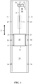
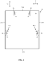
- Figure 1 shows a side view and figure 2 shows a horizontal cross-sectional view of the elevator.
- the elevator may comprise a car 10, an elevator shaft 20, hoisting machinery 30, ropes 42, and a counterweight 41.
- a separate or an integrated car frame 11 may surround the car 10.
- the hoisting machinery 30 may be positioned in the shaft 20.
- the hoisting machinery may comprise a drive 31, an electric motor 32, a traction sheave 33, and a machinery brake 34.
- the hoisting machinery 30 may move the car 10 in a vertical direction Z upwards and downwards in the vertically extending elevator shaft 20.
- the machinery brake 34 may stop the rotation of the traction sheave 33 and thereby the movement of the elevator car 10.
- the car frame 11 may be connected by the ropes 42 via the traction sheave 33 to the counterweight 41.
- the car frame 11 may further be supported with guide means 27 at guide rails 25 extending in the vertical direction in the shaft 20.
- the guide means 27 may comprise rolls rolling on the guide rails 25 or gliding shoes gliding on the guide rails 25 when the car 10 is moving upwards and downwards in the elevator shaft 20.
- the guide rails 25 may be attached with fastening brackets 26 to the wall 21 or to some other support structure in the elevator shaft 20.
- the guide means 27 keep the car 10 in position in the horizontal plane when the car 10 moves upwards and downwards in the elevator shaft 20.
- the counterweight 41 may be supported in a corresponding way on guide rails that are attached to the wall 21 or to some other support structure in the shaft 20.
- the walls 21 of the shaft 20 may be formed of solid walls 21 or of an open beam structure or of any combination of these. One or more of the walls may thus be solid and one or more of the walls may be formed of an open beam structure.
- the shaft 20 may be comprise a front wall 21A, a back wall 21B and two opposite side walls 21C, 21D.
- the two car guide rails 25 may be positioned on opposite side walls 21C, 21D of the shaft 20.
- the two counterweight guide rails 25 may be positioned on the back wall 21B of the shaft 20.
- the guide rails 25 may extend vertically along the height of the elevator shaft 20.
- the guide rails 25 may thus be formed of guide rail elements of a certain length e.g. 5 m.
- the guide rail elements 25 may be installed end-on-end one after the other. Connection plates may be used to attach the ends of the guide rail elements 25.
- the guide rails 25 may be attached to the walls 21 or to some other support structure in the elevator shaft 20 with fastening brackets 26.
- the car 10 may transport people and/or goods between the landings in the building.
- FIG. 2 shows plumb lines PL1, PL2 in the shaft 20.
- the plumb lines PL1, PL2 may be produced by plumbing of the shaft 20 at the beginning of the installation of the elevator.
- the plumb lines PL1, PL2 may be formed with traditional vires or with light sources e.g. lasers having the beams directed upwards along the plumb lines PL1, PL2.
- One plumb line and a gyroscope or two plumb lines are normally needed for a global measurement reference in the shaft 20.
- Figure 1 shows the vertical direction Z i.e. the direction in which the car 10 moves in the elevator shaft 20.
- Figure 2 shows a first horizontal direction X, which is the direction between the side walls (DBG) in the shaft 20 and a second horizontal direction Y, which is the direction from the back wall to the front wall (BTF) in the shaft 20.
- the first horizontal direction X is perpendicular to the second horizontal direction Y.
- the first horizontal direction X and the second horizontal direction Y are both perpendicular to the vertical direction Z.
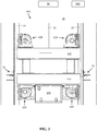
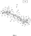
- Figure 3 shows a first cross-sectional view of a platform used to transport alignment equipment in a shaft and figure 4 shows a second cross-sectional view of the platform of figure 3 .
- the first cross-sectional view is in the direction between the guide rails (DBG) in the shaft 20 and the second cross-sectional view is in the direction from the back to the front (BTF) in the shaft 20.
- the platform 400 may comprise a frame structure 410 being formed of horizontal and/or vertical beams.
- the frame structure 410 may be supported with guide means 420 on opposite guide rails 25 in the shaft 20.
- the embodiment comprises four guide means 420 i.e. one guide means 420 in each corner of the platform 400.
- Each guide means 420 may comprise three rollers acting on respective guide surfaces of the guide rail 25.
- a transverse cross section of the guide rail 25 may have the form of a letter T.
- the guide rail 25 may be attached from the horizontal branch i.e. the bottom branch of the letter T via brackets to a wall of the shaft 20.
- the vertical branch i.e. the guide branch of the letter T comprises two opposite side guide surfaces and one front guide surface.
- a circumference of the roller in the guide means 420 may act on a respective guide surface in the guide rail 25.
- the platform 400 may be connected to a hoisting member 51 of a hoist 50.
- the hoist 50 may be positioned in a top end portion of the shaft 20.
- the platform 400 may thus be moved along the guide rails 25 upwards and downwards in the shaft 20 with the hoist 50.
- the hoist 50 may be supported on the walls 21A, 21B, 21C, 21D of the shaft 20 or on some other support structure in the shaft 20.
- the hoisting member 51 may be formed of a wire.
- the hoist 50 could as an alternative be positioned in a bottom end portion of the shaft 20.
- the hoisting member 51 would then pass over a deflection sheave positioned in a top end portion of the shaft 20.
- the platform 400 may be provided with sensors and/or cameras 430 for monitoring the automatic operations of the platform 400.
- the platform 400 may be provided with a sensor e.g. an encoder acting on the guide rail 25 for monitoring the vertical Z height position of the platform 400 in the shaft 20.
- the position of the bolts in the fastening brackets may be detected with sensors and/or cameras.
- a microwave distance measurement and/or a laser measurement could be used to detect an edge of the fastening bracket in order to determine the position of the bolts in the fastening brackets.
- Another possibility would be to use computer vision i.e. a camera and a program to detect the bolts in the fastening brackets.
- An alignment tool 300 and a bolting tool 350 may be supported on the platform 400.
- the alignment tool 300 may be used to align the guide rails 25 and the bolting tool 350 may be used to operate i.e. open and close the bolts of the fastening brackets of the guide rails 25 during the alignment of the guide rails 25.
- the alignment tool 300, the bolting tool 350 and the hoist 50 moving the platform 400 upwards and downwards in the shaft 20 may be controlled with a control unit 500 positioned outside the shaft 20.
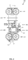
- Figure 5 shows an axonometric view of a bolting tool on the platform of figure 3 .
- the bolting tool 350 may comprise an actuator 351 and a bushing 352.
- the actuator 351 may be an electric motor for rotating the bushing 352.
- the bushing 352 may form a form lock on a head of a tightening bolt in the fastening bracket 26.
- the form lock may connect the bushing 352 to the head of the bolt so that the tightening bolt will rotate along with the bushing 352.
- the bolting tool 350 be used to open and close the bolts in the fastening brackets 26 of the guide rails 25. Only one bolting tool 350 may be used, whereby the bolting tool 350 may be movable on the platform 400 across the shaft 20 between the two opposite guide rails 25. Another possibility is to use two bolting tools 350 i.e. a bolting tool 350 at each side of the platform 400.
- the bolting tool 350 may be arranged so that the bolting tool 350 is movable in the first horizontal direction X and/or in the second horizontal direction Y and/or in the vertical direction Z on the platform 400.
- the bolting tool 350 may be supported on a first frame structure 370 so that the bolting tool 350 may be moved upwards and downwards in the vertical direction Z in the first framer structure 370.
- the first frame structure 370 may be supported on a second frame structure 380 being movable along rails in the second horizontal direction Y.
- the second frame structure 380 may be supported on a third frame structure 390 being movable along rails in the first horizontal direction Y.
- the position of the bolts in the fastening brackets 26 may be detected with sensors and/or cameras 360.
- a microwave distance measurement and/or a laser measurement could be used to detect an edge of the fastening bracket 26 in order to determine the position of the bolts in the fastening brackets 26.
- Another possibility would be to use computer vision i.e. a camera and a program to detect the bolts in the fastening brackets 26.
- the bracket 26 may comprise two bracket parts 60, 70.
- the horizontal branches of the two bracket parts 60, 70 may be attached to each other in fastening points P1 with a first vertical fastening member 80.
- a second horizontal fastening member 90 may extend into a nest 63 formed in connection with the horizontal branches of the bracket parts 60, 70.
- the second fastening member 90 may be connected to the first fastening member 80 via a power transmission. Tightening and loosening of the second fastening member 90 will tighten and loosen the compression joint of the first fastening member 80 in the first fastening point P1.
- Tightening and loosening of the first fastening members 80 forming the compression joints between the two bracket parts 60, 70 may thus be done by tightening and loosening the second fastening member 90.
- the second fastening member 90 may be operated from the front side of the bracket 26.
- Figure 6 shows an axonometric view of an alignment tool for aligning guide rails in a shaft.
- the alignment tool 300 may comprise a positioning unit 100 and an alignment unit 200.
- the positioning unit 100 may comprise a longitudinal first frame 110 extending across the shaft 20 in the first horizontal direction X.
- the first frame 110 may comprise a middle portion 111 and two opposite end portions 112, 113.
- the two opposite end portions 112, 113 may be mirror images of each other.
- Each end of the first frame 110 may be provided with a first attachment means 140, 150.
- Each of the first attachment means 140, 150 may be movable individually in the first horizontal direction X with a first actuator 141, 151 (position shown only schematically in the figure) e.g. a linear motor.
- the first attachment means 140, 150 may be used to lock the positioning unit 100 between the walls or any other suitable support structures in the elevator shaft 20.
- the alignment unit 200 may comprise a longitudinal second frame 210 extending across the shaft 20 in the first horizontal direction X.
- the second frame 210 may comprise a middle portion 211 and two opposite end portions 212, 213.
- the two opposite end portions 212, 213 may be mirror images of each other.
- Each end of the second frame 210 may comprise a second attachment means 240, 250.
- Each of the second attachment means 240, 250 may be movable individually in the first horizontal direction X with a second actuator 241, 251, e.g. a linear motor.
- Each of the second attachment means 240, 250 may further comprise gripping means in the form of jaws 245, 255 positioned at the end of the second attachment means 240, 250.
- Each of the jaws 245, 255 may be movable individually in the second horizontal direction Y perpendicular to the first horizontal direction X with a third actuator 246, 256 e.g. a linear motor. The jaws 245, 255 will thus grip on the opposite side surfaces of the guide rails 25.
- Each end of the second frame 210 may be attached to the first frame 110 with support parts 260, 270.
- Each support part 260, 270 may be individually movable in the second horizontal direction Y in relation to the positioning unit 100 with a fourth actuator 261, 271, e.g. a linear motor.
- the alignment unit 200 may be attached with articulated joints J1, J2 to the support parts 260, 270.
- the articulated joints J1, J2 make it possible to adjust the alignment unit 200 so that it is non-parallel to the positioning unit 100.
- Each of the second attachment means 240, 250 may be moved with a respective second actuator 241, 251 only in the first horizontal direction X. It would, however, be possible to add a further actuator to one of the second attachment means 240, 250 in order to be able to turn said second attachment means 240, 250 in the horizontal plane around an articulated joint. It seems that such a possibility is not needed, but such a possibility could be added to the alignment tool 300 if needed.
- the alignment tool 300, the bolting tool 350 and the hoist 50 for moving the platform 400 may be operated through a control unit 500.
- the control unit 500 may be positioned outside the shaft 20 e.g. in a control space.
- the control unit 500 may control the actuators 141, 142, 241, 242, 246, 256, 261, 271 on the alignment tool 300.
- the communication between the control unit 500 and the alignment tool 300, the bolting tool 350 and the hoist 50 for moving the platform 400 may be wireless.
- the operation of the alignment tool 300 may be divided into two phases.
- the first phase is described in connection with figure 6 and the second phase is described in connection with figure 7 .
- Figure 7 shows a first phase of the operation of the alignment tool of figure 6 .
- the figure shows the car guide rails 25 at opposite sides of the shaft 20 attached to brackets 26 and the counterweight guide rails 25 at the back of the shaft 20 attached to brackets.
- the alignment tool 300 extends between the car guide rails 25.
- the platform 400 and thereby also the alignment tool 300 may be lifted with the lift 50 to a first bracket 26 location during the alignment of the guide rails 25.
- the alignment tool 300 is then operated through the control unit 500 to activate the second actuators 241, 251 to move the jaws 245, 255 at the outer ends of the second attachment means 240, 250 in the first horizontal direction X into contact with the opposite guide rails 25.
- the third actuators 246, 256 are then activated to move the jaws 245, 255 at the outer ends of the second attachment means 240, 250 in the second horizontal direction Y in order to grip on the opposite vertical side surfaces of the guide rails 25.
- the bolting tool 350 is then activated to open the bracket 26 bolts on both sides of the shaft 20 so that the guide rails 25 can be moved.
- the alignment between the opposite guide rails 25 and the internal distance between the opposite guide rails 25 is then adjusted with the alignment unit 200.
- the second frame 210 of alignment unit 200 is stiff so that the two opposite guide rails 25 will be positioned with the apexes facing towards each other when the gripping means 245, 255 grips the guide rails 25. There is thus no twist between the opposite guide rails 25 after this.
- the internal distance between the two opposite guide rails 25 in the DBG direction is also adjusted with the alignment unit 200.
- the position of the second attachment means 240, 250 in relation to each other in the first horizontal direction X determines said distance.
- a plump line PL1, PL2 may be formed in the vicinity of each guide rail 25 (shown in figure 2 ).
- a measurement system may further be positioned on the platform 400 for measuring the distance in the first horizontal direction X and in the second horizontal direction Y from the respective guide rail 25 to the plumb line PL1, PL2 that is in the vicinity of said guide rail 25.
- the difference to a predetermined target value is then determined.
- the needed control values (DBG, BTF and twist) are calculated.
- the control values may then be transformed into incremental steps, which are fed as control signals to the control units of the linear motors in the alignment tool 300.
- the DBG can also be measured based on the motor torque, which indicates when the second attachment means 240, 250 have reached their end position and are positioned against the guide rails 25.
- the position of the linear motors can then be read from the display of the control unit 500.
- the distance between the guide rails 25 may thus be calculated based on the distance of the guide rails 25 to the plumb lines PL1, PL2 and based on the position of each of the second attachment means 240, 250 in the first horizontal direction X.
- Figure 8 shows a second phase of the operation of the alignment tool of figure 6 .
- the figure shows the car guide rails 25 at opposite sides of the shaft 20 attached to brackets 26 and the counterweight guide rails 25 at the back of the shaft 20 attached to brackets.
- the alignment tool 300 extends between the car guide rails 25.
- the first actuators 141, 151 are activated to move the first attachment means 140, 150 at the outer end of the positioning unit 100 into contact with the wall constructions or other support structures in the elevator shaft 20.
- the positioning unit 100 is now locked in relation to the shaft 20 in the second horizontal direction Y.
- the alignment unit 200 is in a floating mode in relation to the locked positioning unit 100.
- the guide rails 25 can now be adjusted with the alignment unit 200 and the positioning unit 100 in relation to the shaft 20. The adjustment is made based on the measurements in relation to the plumb lines PL1, PL2 made earlier.
- the bolts in the brackets 26 may, after the adjustments have been done, be tightened with the bolting unit 350.
- the alignment tool 300 may now be transported to the next bracket 26 location where the first phase and the second phase of the operation of the alignment tool 300 may be repeated.
- Figures 9 shows a side view of a fastening bracket for elevator guide rails.
- the directions X, Y, Z in the figure refer to a situation in which the fastening bracket is used to support car guide rails positioned on opposite side walls of the shaft 20.
- the fastening bracket 26 may comprise two bracket parts 60, 70.
- Each bracket part 60, 70 may comprise a vertical branch 61, 71 and a horizontal branch 62, 72.
- the vertical branch 61 of the first bracket part 60 may be attached to a wall 21 of the shaft 20. This can be done with a bolt which is not shown in the figure.
- the guide rail 25 may be attached to the vertical branch 71 of the second bracket part 70.
- the guide rail 25 may be attached with fastening members 95 and clips 96 to the vertical branch 71 of the second bracket part 70.
- the bracket parts 60, 70 may have a width direction W and a perpendicular depth direction D.
- the vertical branch 61 of the first bracket part 60 may face towards the wall in the shaft 20 to which the vertical branch 61 of the first bracket part 60 is attached to.
- the vertical branch 71 of the second bracket part 70 may face outwards from the wall in the shaft 20 to which the vertical branch 61 of the first bracket part 60 is attached to.
- the horizontal branch 72 of the second bracket part 70 may be positioned on the horizontal branch 62 of the first bracket part 60.
- the horizontal branch 62 of the first bracket part 60 and the horizontal branch 72 of the second bracket part 70 may be attached to each other through at least two fastening points P1, P2.
- Each fastening point P1, P2 may comprise a longitudinal opening 061, 071 in each horizontal branch 62, 72 of the two bracket parts 60, 70.
- the two longitudinal openings 061, 071 pass vertically through the respective horizontal branch 62, 72 of the two bracket parts 60, 70.
- a first longitudinal opening 061 may be provided in the horizontal branch 62 of the first bracket part 60 and a second longitudinal opening 071 may be provided in the horizontal branch 72 of the second bracket part 70.
- the first longitudinal opening 061 may extend in the width direction W within the horizontal branch 62 of the first bracket part 60.
- the second longitudinal opening 071 may extend in the depth direction D within the horizontal branch 72 of the second bracket part 70.
- the first longitudinal opening 061 and the second longitudinal opening 071 may extend in perpendicular directions.
- a nest 63 may be arranged in connection with the horizontal branch 62 of the first bracket part 60.
- the nest 63 may be supported on the horizontal branch 62 of the first bracket part 60.
- the nest 63 may comprise a front wall 63A extending vertically outwards from the horizontal branch 62 of the first bracket part 60 and an outer wall 63B extending horizontally from the front wall 63A.
- a first end of the front wall 63A may be attached to the horizontal branch 62 of the first bracket part 60.
- a second opposite end of the front wall 63A may be attached to a first end of the outer wall 63B.
- the outer wall 63B may extend from the second end of the front wall 63A backwards towards the vertical branch 61 of the first bracket part 60.
- the front wall 63A and the outer wall 63B of the nest 63 may be made by bending the horizontal branch 62 of the first bracket part 60.
- the front wall 63A extends downwards from the outer end of the horizontal branch 62 of the first bracket part 60 and the outer wall 63B extends backwards from the outer end of the front wall 63A.
- the nest 63 has the shape of a lying letter U.
- the front wall 63A closes the front of the nest 63, but the sides and the back of the nest 63 may be open.
- the front wall 63A of the nest 63 may face outwards from the wall in the shaft 20 to which the vertical branch 61 of the first bracket part 60 is attached to.
- a first fastening member 80 may extend vertically through the longitudinal openings 061, 071 in the horizontal branches 62, 72 of the bracket parts 60, 70 and further into the nest 63.
- the first fastening member 80 may have a bolt-shape.
- the first fastening member 80 may comprise a head 81 and a shank 82 with an outer end 83.
- the head 81 may seat on the upper surface of the horizontal branch 72 of the second bracket part 70.
- the shank 82 may extend from the head 81 to the outer wall 63B of the nest 63.
- the horizontal cross-section of the shank 82 may be circular.
- the outer end 83 of the shank 82 may extend into a fourth longitudinal slit O63 provided on the outer wall 63B of the nest 63.
- the horizontal cross-section of the outer end 83 of the shank 82 may be rectangular.
- the fourth longitudinal slit O63 may extend in the width direction W.
- the fourth longitudinal slit O63 may be formed of a fourth longitudinal opening O63 in the outer wall 63B of the nest 63.
- Another possibility would be to form the fourth longitudinal slit O63 with two upwards extending side walls on the horizontal bottom wall 63B. The two side walls would be parallel and extend in the width direction W. The fourth slit O63 would thus be formed between the two side walls.
- the outer wall 63B of the nest 63 could thus be solid.
- the outer end 83 of the first fastening member 80 may be supported within the fourth longitudinal slit O63 in the outer wall 63B of the nest 63 so that the outer wall 63B of the nest 63 is movable along the fourth longitudinal slit O63 in relation to the outer end 83 of the first fastening member 80.
- the outer end 83 of the first fastening member 80 is on the other hand supported against movement in a direction perpendicular to the fourth longitudinal slit O63.
- the shank 82 of the first fastening member 80 may comprise a wedge opening O80 passing horizontally through the shank 82 of the first fastening member 80.
- the wedge opening O80 may have a longitudinal shape with a first edge positioned near the outer wall 63B of the nest 63 and a second edge positioned within the longitudinal openings 061, 071 in the horizontal branches 62, 72 of the two bracket parts 60, 70.
- the wedge opening O80 may extend along a longitudinal centre axis of the first fastening member 80.
- a second fastening member 90 may extend horizontally into the nest 63 through a third longitudinal opening O62 in the front wall 63A of the nest 63.
- the third longitudinal opening O62 may extend in the width direction W.
- the second fastening member 90 may be rotatably and movably supported on the vertical front wall 63A of the nest 63. This may be done e.g. with washers positioned on both sides of the vertical front wall 63A of the nest 63. The washers may be fixed to the second fastening member 90.
- the second fastening member 90 may have a bolt-shape.
- the second fastening member 90 may comprise a head 91 and a shank 92. At least an outer end of the shank 92 may be provided with an outer threading.
- the second fastening member 90 may thus be rotated around a longitudinal centre axis of the second fastening member 90.
- the nest 63 may move laterally in the width direction W along the third longitudinal opening O62 in relation to the second
- a power transmission 93 may be operatively connected within the nest 63 to the second fastening member 90 and to the first fastening member 80.
- the power transmission 93 may transfer the rotational movement of the second fastening member 90 into a linear vertical movement of the first fastening member 80.
- the power transmission 93 may be formed of a tightening element 93.
- the tightening element 93 and the first fastening member 80 may generate a pressure joint between the horizontal branches 62, 72 of the two bracket parts 60, 70 in the fastening point P1, P2 when the second fastening member 90 is rotated around its longitudinal centre axis.
- the tightening element 93 which is also shown separately in the figure, may be formed as a wedge comprising a first edge 93A and a second opposite edge 93B.
- the first edge 93A may be horizontal and the second edge 93B may be inclined.
- the first edge 93A of the tightening member 93 seats against the lower surface of the horizontal branch 62 of the first bracket part 60.
- the second edge 93B of the tightening element 93 seats against the lower edge of the wedge opening O80 in the first fastening member 80.
- the second edge 93B of the wedge may have an angle ⁇ 1 of inclination in the range of 5 to 20 degrees, advantageously in the range of 5 to 10 degrees.
- the wedge functions as a power transmission, whereby the force applied by the second fastening member 90 on the wedge is fortified by the wedge acting on the first fastening member 80. The rotational movement of the second fastening member 90 is converted into a linear movement of the wedge.
- the tightening element 93 may comprise a connection element 94 for connecting the tightening element 93 to the second fastening member 90.
- the connection element 94 may comprise a hole with an inner threading receiving the outer threading of the shank 92 of the second fastening member 90. Rotation of the second fastening member 90 around the longitudinal centre axis of the second fastening member 90 in a first direction moves the tightening element 93 in depth direction D towards the front wall 63A of the nest 63 and rotation of the second fastening member 90 around the longitudinal centre axis of the second fastening member 90 in a second opposite direction moves the tightening element 93 in the depth direction D away from the front wall 63A of the nest 63.
- the connection element 94 may form an integral part of the tightening element 93. Another possibility is that the connection element 94 is formed as a separate part and connected to the tightening element 93.
- the tightening element 93 works thus as a nut on the first fastening member 80.
- the horizontal branches 62, 72 of the bracket parts 60, 70 are pressed between the head 81 of the first fastening member 80 and the upper edge 93A of the tightening element 93 in the fastening point P1, P2.
- the tightening element 93 may as an alternative be formed so that the first fastening member 80 passes through a longitudinal opening in the tightening element 93.
- the tightening element 93 could in such an embodiment be formed of two sheets, whereby the ends of the two sheets would be attached to each other and the longitudinal opening would be provided in the middle portion of the tightening element 93.
- the first fastening element 80 would then be provided with a flange near the outer end 83 of the first fastening element 80.
- the first upper edges of the tightening element 93 would seat against the lower surface of the horizontal branch 62 of the first bracket part 60 and the second lower edges of the tightening element 93 would seat on the flange.
- the bracket parts 60, 70 may be used to support car guide rails or counterweight guide rails.
- the first bracket part 60 and the second bracket part 70 may thus be adjusted in relation to each other in the first horizontal direction X i.e. in the direction between the guide rails DBG in the shaft 20 when the first fastening member 80 is unlocked.
- the guide rails 25 will thus be adjusted in the direction between the guide rails DBG.
- the guide rails 25 may further be adjusted in the second horizontal direction Y i.e. in the direction from the back to the front BTF in the shaft 20 when the first fastening member 80 is unlocked.
- the twist of the guide rail 25 may further be adjusted by rotating the horizontal branches 62, 72 in relation to each other.
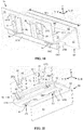
- Figure 10 shows a first and figure 11 shows a second axonometric view of the fastening bracket of figure 9 .
- the bracket parts 60, 70 may have a width W1 in the width direction W i.e. in the Y direction. Both bracket parts 60, 70 may have the same width W1.
- the nest 63 may also have the same width W1 as the bracket parts 60, 70.
- Each of the two bracket parts 60, 70 may comprise a vertical branch 61, 71 and a horizontal branch 62, 72.
- the vertical branch 61 of the first bracket part 60 may be attached to a wall of the shaft. This can be done with a bolt which is not shown in the figure.
- the guide rail may be attached to the vertical branch 71 of the second bracket part 70 with fastening members 95 and clips 96.
- the first fastening member 80 passes vertically Z through the perpendicular longitudinal openings 061, 071 in the horizontal branches 62, 72 of the bracket parts 60, 70 and further into the fourth longitudinal slit O63 in the outer wall 63B of the nest 63.
- the second fastening member 90 passes horizontally in the depth direction D i.e. in the X direction into the nest 63 through the third longitudinal opening O62 in the front wall 63A of the nest 63.
- the horizontal branches 62, 72 of the two bracket parts 60, 70 may be adjusted laterally in relation to each other in the first horizontal direction X and in the second horizontal direction Y due to the perpendicular longitudinal openings 061, 071 in the horizontal branches 62, 72 of the two bracket parts 60, 70.
- Longitudinal openings O62, O63 are further needed in the nest 63 in order to allow said lateral movement.
- the nest 63 is attached to the horizontal branch 62 of the first bracket part 60 and moves along with the first bracket part 60.
- the longitudinal openings O61, O62, O63 in the horizontal branch 62 of the first bracket part 60 and in the nest 63 are parallel and extend in the width direction W.
- the first bracket part 60 and the nest 63 may thus move in relation to the first fastening member 80 and the second fastening member 90 in the width direction W when the first fastening member 80 is unlocked.
- the adjustment of the horizontal branches 62, 72 of the two bracket parts 60, 70 may thus be done from the front of the bracket parts 60, 70.
- the second fastening members 90 extend in the horizontal direction so that a direct horizontal access to the heads 91 of the second fastening members 90 is achieved from an installation platform moving upwards and downwards in the shaft 20.
- the first fastening member 80 may thus be opened and closed by only operating the second fastening member 90. No direct access to the first fastening member 80 is needed.
- the horizontal branches 62, 72 of the two brackets 60, 70 may be adjusted from the installation platform in order to achieve a correct position of the guide rail 25.
- the bolting unit 350 may thus work directly from the front of the bracket parts 60, 70.
- the bolting unit 350 may be movably installed on the platform 400.
- the bolting tool 350 may be movable in the first horizontal direction X and/or in the second horizontal direction Y and/or in the vertical direction Z.
- the bolting tool 350 may first be moved in the second horizontal direction Y and in the vertical direction Z in order to position the bolting tool 350 in line with the head 91 of the second fastening member 90 in each fastening point P1, P2.
- the bolting tool 350 may thereafter be moved in the first horizontal direction X into contact with the head 91 of the second fastening member 90.
- the bushing 352 of the bolting tool 350 is thus positioned on the head 91 of the second fastening member 90.
- the actuator 351 may then rotate the bushing 352 in order to tighten and/or loose the second fastening member 90 and thereby also the first fastening member 80.
- the guide rail is positioned on a middle portion in the width direction W of the vertical branch 71 of the second bracket part 70.
- the second fastening members 90 are positioned on both sides of the guide rail on outer portions of the front wall 63A of the nest 63. There is thus a free horizontal access to the second fastening members 90 from an installation platform moving in the shaft.
- the fastening bracket arrangement based on the two bracket parts 60, 70 shown in the figures for attaching guide rails 25 to the walls 21 or other support structures in the shaft 20 may advantageously be used in the inventive arrangement for aligning guide rails 25 in a shaft 20.
- the bracket parts 60, 70 may be made of sheet material e.g. of a metal.
- the starting point may be a straight metal sheet having a suitable width and length.
- the metal sheet may then be bent into the desired form comprising the vertical branch 61, 71 and the horizontal branch 62, 72.
- the nest 63 may be made by bending from the same metal sheet in the embodiments in which the nest 63 is formed on the outer end of the horizontal branch 61 of the bracket part 60.
- the nest 63 may in other embodiments be formed as a separate part, whereby the vertical front wall 63A of the nest 63 may be attached to the horizontal branch 61, 71 of the bracket part 60, 70 e.g. by welding.
- the tightening element 93 may be made from a sheet material e.g. of metal.
- the invention may be used for fastening car guide rails and counterweight guide rails to the walls 21 in the shaft 20.
- the use of the invention is not limited to the elevator disclosed in the figures.
- the invention can be used in any type of elevator e.g. an elevator comprising a machine room or lacking a machine room, an elevator comprising a counterweight or lacking a counterweight.
- the counterweight could be positioned on either side wall or on both side walls or on the back wall of the elevator shaft.
- the drive, the motor, the traction sheave, and the machine brake could be positioned in a machine room or somewhere in the elevator shaft.
- the car guide rails could be positioned on opposite side walls of the shaft or on a back wall of the shaft in a so called ruck-sack elevator.
Landscapes
- Lift-Guide Devices, And Elevator Ropes And Cables (AREA)
Abstract
The method comprises supporting a platform (400) movably on guide rails (25), moving the platform with a hoist, aligning the guide rails with an alignment tool (300) supported on the platform, the alignment tool comprising a positioning unit and an alignment unit, each end of the positioning unit comprising a movable first attachment means for supporting the positioning unit in the elevator shaft, each end of the alignment unit comprising a movable gripping means for gripping on the guide rail, opening and closing fastening bracket bolts with a bolting tool (350) supported on the platform, controlling the hoist, the alignment tool, and the bolting tool during alignment of the guide rails with a control unit.
Description
- The invention relates to a method and an arrangement for aligning elevator guide rails.
- An elevator may comprise a car, a shaft, hoisting machinery, ropes, and a counterweight. A separate or an integrated car frame may surround the car.
- The hoisting machinery may be positioned in the shaft. The hoisting machinery may comprise a drive, an electric motor, a traction sheave, and a machinery brake. The hoisting machinery may move the car upwards and downwards in the shaft. The machinery brake may stop the rotation of the traction sheave and thereby the movement of the elevator car.
- The car frame may be connected by the ropes via the traction sheave to the counterweight. The car frame may further be supported with guide means at guide rails extending in the vertical direction in the shaft. The guide rails may be attached with fastening brackets to the side wall structures in the shaft. The guide means keep the car in position in the horizontal plane, when the car moves upwards and downwards in the shaft. The counterweight may be supported in a corresponding way on guide rails that are attached to the wall structure of the shaft.
- The car may transport people and/or goods between the landings in the building. The wall structure of the shaft may be formed of solid walls or of an open beam structure or of any combination of these.
- The guide rails may be formed of guide rail elements of a certain length. The guide rail elements may be connected in the installation phase end-on-end one after the other in the elevator shaft. The ends of the guide rail elements may be attached to each other with connection plates or form locking means. The guide rails may be attached to the walls of the elevator shaft with fastening brackets.
- The fastening brackets may comprise three bracket parts i.e. two L-shaped and one straight bracket part. The horizontal branches of the L-shaped bracket parts may be attached to each other in two first fastening points. Each first fastening point may comprise a longitudinal opening, a hole and a first fastening member passing through the longitudinal opening and the hole. The longitudinal opening may allow for adjustment of the horizontal branches of the two L-shaped bracket parts in relation to each other in a first horizontal direction. The third bracket part may be attached to the vertical branch of the second bracket part in two second fastening points. Each second fastening point may comprise a longitudinal opening, a hole and a second fastening member passing through the longitudinal opening and the hole. The longitudinal opening may allow for adjustment of the second bracket part and the third bracket part in relation to each other in a second horizontal direction perpendicular to the first horizontal direction. The bracket parts may thus be adjusted in two perpendicular horizontal directions in order to align the guide rails. The vertical branch of the first bracket part may be attached to a wall in the shaft. The guide rail may be attached to the third bracket part.
- The first fastening points are directed in the vertical direction and positioned behind the vertical branch of the second bracket part. The access to the first fastening points is thus problematic.
- Aligning of the guide rails have in prior art solutions been done by driving the elevator car or a separate installation platform at inspection speed in the shaft. One or more mechanics have been working on the roof of the elevator car or on the installation platform during the alignment of the guide rails. The alignment of the guide rails has been done manually. An automated alignment tool extending across the shaft and being supported on the car roof or on the installation platform may also have been used. The technician has controlled the automated alignment via a control unit positioned on the automated alignment tool or on the car roof or on the installation platform.
- The car or the installation platform have due to safety reasons been driven at a low inspection speed in prior art solutions, which means that the alignment has been time consuming. The need for one or more technicians on the car roof or on the installation platform results in that strict safety regulations must be followed in the work. The ergonomics for the technicians working on the car roof or on the installation platform has also not been optimal in prior art solutions.
- An object of the invention is an improved method and arrangement for aligning elevator guide rails.
- The method for aligning elevator guide rails according to the invention is defined in
claim 1. - The arrangement for aligning elevator guide rails according to the invention is defined in claim 7.
- The novel method and arrangement for aligning guide rails may result in a fully automated alignment process. A mechanic is not needed in the shaft as the control of the whole alignment process may be done by a control unit positioned outside the elevator shaft. The speed of the alignment and the safety is thus improved and the problems relating to ergonomics is eliminated as technicians are not needed on the platform.
- The invention may improve the quality of the alignment as such and the invention may also contribute in maintaining a constant quality throughout the whole alignment process.
- The invention may also result in operational cost savings because less personnel is needed in the guide rail alignment process. It may be possible to use personnel for other tasks during the guide rail alignment.
- A bolting tool may be supported on the platform for loosening and tightening the bolts in the fastening brackets. An alignment tool may further be supported on the platform for aligning the guide rails when the tightening bolts in the fastening brackets have been loosened with the bolting tool.
- The invention will in the following be described in greater detail by means of preferred embodiments with reference to the attached drawings, in which
-
Figure 1 shows a side view of an elevator, -
Figure 2 shows a horizontal cross-sectional view of the elevator, -
Figure 3 shows a first cross-sectional view of a platform used to transport alignment equipment in a shaft, -
Figure 4 shows a second cross-sectional view of the platform offigure 3 , -
Figure 5 shows an axonometric view of a bolting tool on the platform offigure 3 , -
Figure 6 shows an axonometric view of an alignment tool for aligning guide rails in a shaft, -
Figure 7 shows a first phase of the operation of the alignment tool offigure 5 , -
Figure 8 shows a second phase of the operation of the alignment tool offigure 6 , -
Figures 9 shows a side view of a fastening bracket for elevator guide rails, -
Figure 10 shows a first axonometric view of the fastening bracket offigure 9 , -
Figure 11 shows a second axonometric view of the fastening bracket offigure 9 . -
Figure 1 shows a side view andfigure 2 shows a horizontal cross-sectional view of the elevator. - The elevator may comprise a
car 10, anelevator shaft 20, hoistingmachinery 30,ropes 42, and acounterweight 41. A separate or anintegrated car frame 11 may surround thecar 10. - The hoisting
machinery 30 may be positioned in theshaft 20. The hoisting machinery may comprise a drive 31, anelectric motor 32, atraction sheave 33, and amachinery brake 34. The hoistingmachinery 30 may move thecar 10 in a vertical direction Z upwards and downwards in the vertically extendingelevator shaft 20. Themachinery brake 34 may stop the rotation of thetraction sheave 33 and thereby the movement of theelevator car 10. - The
car frame 11 may be connected by theropes 42 via thetraction sheave 33 to thecounterweight 41. Thecar frame 11 may further be supported with guide means 27 atguide rails 25 extending in the vertical direction in theshaft 20. The guide means 27 may comprise rolls rolling on the guide rails 25 or gliding shoes gliding on the guide rails 25 when thecar 10 is moving upwards and downwards in theelevator shaft 20. The guide rails 25 may be attached withfastening brackets 26 to thewall 21 or to some other support structure in theelevator shaft 20. The guide means 27 keep thecar 10 in position in the horizontal plane when thecar 10 moves upwards and downwards in theelevator shaft 20. Thecounterweight 41 may be supported in a corresponding way on guide rails that are attached to thewall 21 or to some other support structure in theshaft 20. - The
walls 21 of theshaft 20 may be formed ofsolid walls 21 or of an open beam structure or of any combination of these. One or more of the walls may thus be solid and one or more of the walls may be formed of an open beam structure. Theshaft 20 may be comprise afront wall 21A, aback wall 21B and twoopposite side walls guide rails 25 for thecar 10. The twocar guide rails 25 may be positioned onopposite side walls shaft 20. There may further be twoguide rails 25 for thecounterweight 41. The twocounterweight guide rails 25 may be positioned on theback wall 21B of theshaft 20. - The guide rails 25 may extend vertically along the height of the
elevator shaft 20. The guide rails 25 may thus be formed of guide rail elements of a certain length e.g. 5 m. Theguide rail elements 25 may be installed end-on-end one after the other. Connection plates may be used to attach the ends of theguide rail elements 25. The guide rails 25 may be attached to thewalls 21 or to some other support structure in theelevator shaft 20 withfastening brackets 26. - The
car 10 may transport people and/or goods between the landings in the building. -
Figure 2 shows plumb lines PL1, PL2 in theshaft 20. The plumb lines PL1, PL2 may be produced by plumbing of theshaft 20 at the beginning of the installation of the elevator. The plumb lines PL1, PL2 may be formed with traditional vires or with light sources e.g. lasers having the beams directed upwards along the plumb lines PL1, PL2. One plumb line and a gyroscope or two plumb lines are normally needed for a global measurement reference in theshaft 20. -
Figure 1 shows the vertical direction Z i.e. the direction in which thecar 10 moves in theelevator shaft 20.Figure 2 shows a first horizontal direction X, which is the direction between the side walls (DBG) in theshaft 20 and a second horizontal direction Y, which is the direction from the back wall to the front wall (BTF) in theshaft 20. The first horizontal direction X is perpendicular to the second horizontal direction Y. The first horizontal direction X and the second horizontal direction Y are both perpendicular to the vertical direction Z. -
Figure 3 shows a first cross-sectional view of a platform used to transport alignment equipment in a shaft andfigure 4 shows a second cross-sectional view of the platform offigure 3 . - The first cross-sectional view is in the direction between the guide rails (DBG) in the
shaft 20 and the second cross-sectional view is in the direction from the back to the front (BTF) in theshaft 20. - The
platform 400 may comprise aframe structure 410 being formed of horizontal and/or vertical beams. Theframe structure 410 may be supported with guide means 420 onopposite guide rails 25 in theshaft 20. The embodiment comprises four guide means 420 i.e. one guide means 420 in each corner of theplatform 400. Each guide means 420 may comprise three rollers acting on respective guide surfaces of theguide rail 25. A transverse cross section of theguide rail 25 may have the form of a letter T. Theguide rail 25 may be attached from the horizontal branch i.e. the bottom branch of the letter T via brackets to a wall of theshaft 20. The vertical branch i.e. the guide branch of the letter T comprises two opposite side guide surfaces and one front guide surface. A circumference of the roller in the guide means 420 may act on a respective guide surface in theguide rail 25. - The
platform 400 may be connected to a hoistingmember 51 of a hoist 50. The hoist 50 may be positioned in a top end portion of theshaft 20. Theplatform 400 may thus be moved along the guide rails 25 upwards and downwards in theshaft 20 with the hoist 50. The hoist 50 may be supported on thewalls shaft 20 or on some other support structure in theshaft 20. The hoistingmember 51 may be formed of a wire. The hoist 50 could as an alternative be positioned in a bottom end portion of theshaft 20. The hoistingmember 51 would then pass over a deflection sheave positioned in a top end portion of theshaft 20. - The
platform 400 may be provided with sensors and/orcameras 430 for monitoring the automatic operations of theplatform 400. Theplatform 400 may be provided with a sensor e.g. an encoder acting on theguide rail 25 for monitoring the vertical Z height position of theplatform 400 in theshaft 20. The position of the bolts in the fastening brackets may be detected with sensors and/or cameras. A microwave distance measurement and/or a laser measurement could be used to detect an edge of the fastening bracket in order to determine the position of the bolts in the fastening brackets. Another possibility would be to use computer vision i.e. a camera and a program to detect the bolts in the fastening brackets. - An
alignment tool 300 and abolting tool 350 may be supported on theplatform 400. Thealignment tool 300 may be used to align the guide rails 25 and thebolting tool 350 may be used to operate i.e. open and close the bolts of the fastening brackets of the guide rails 25 during the alignment of the guide rails 25. - The
alignment tool 300, thebolting tool 350 and the hoist 50 moving theplatform 400 upwards and downwards in theshaft 20 may be controlled with acontrol unit 500 positioned outside theshaft 20. -
Figure 5 shows an axonometric view of a bolting tool on the platform offigure 3 . - The
bolting tool 350 may comprise anactuator 351 and abushing 352. Theactuator 351 may be an electric motor for rotating thebushing 352. Thebushing 352 may form a form lock on a head of a tightening bolt in thefastening bracket 26. The form lock may connect thebushing 352 to the head of the bolt so that the tightening bolt will rotate along with thebushing 352. - The
bolting tool 350 be used to open and close the bolts in thefastening brackets 26 of the guide rails 25. Only onebolting tool 350 may be used, whereby thebolting tool 350 may be movable on theplatform 400 across theshaft 20 between the two opposite guide rails 25. Another possibility is to use twobolting tools 350 i.e. abolting tool 350 at each side of theplatform 400. Thebolting tool 350 may be arranged so that thebolting tool 350 is movable in the first horizontal direction X and/or in the second horizontal direction Y and/or in the vertical direction Z on theplatform 400. Thebolting tool 350 may be supported on afirst frame structure 370 so that thebolting tool 350 may be moved upwards and downwards in the vertical direction Z in thefirst framer structure 370. Thefirst frame structure 370 may be supported on asecond frame structure 380 being movable along rails in the second horizontal direction Y. Thesecond frame structure 380 may be supported on athird frame structure 390 being movable along rails in the first horizontal direction Y. - The position of the bolts in the
fastening brackets 26 may be detected with sensors and/orcameras 360. A microwave distance measurement and/or a laser measurement could be used to detect an edge of thefastening bracket 26 in order to determine the position of the bolts in thefastening brackets 26. Another possibility would be to use computer vision i.e. a camera and a program to detect the bolts in thefastening brackets 26. - The
bracket 26 may comprise twobracket parts bracket parts vertical fastening member 80. A secondhorizontal fastening member 90 may extend into anest 63 formed in connection with the horizontal branches of thebracket parts second fastening member 90 may be connected to thefirst fastening member 80 via a power transmission. Tightening and loosening of thesecond fastening member 90 will tighten and loosen the compression joint of thefirst fastening member 80 in the first fastening point P1. - Tightening and loosening of the
first fastening members 80 forming the compression joints between the twobracket parts second fastening member 90. Thesecond fastening member 90 may be operated from the front side of thebracket 26. -
Figure 6 shows an axonometric view of an alignment tool for aligning guide rails in a shaft. - The
alignment tool 300 may comprise apositioning unit 100 and analignment unit 200. - The
positioning unit 100 may comprise a longitudinalfirst frame 110 extending across theshaft 20 in the first horizontal direction X. Thefirst frame 110 may comprise amiddle portion 111 and twoopposite end portions opposite end portions middle portions 111 of different lengths or themiddle portion 111 could be left out in order to adjust the length of thepositioning unit 100 todifferent elevator shafts 20. Each end of thefirst frame 110 may be provided with a first attachment means 140, 150. Each of the first attachment means 140, 150 may be movable individually in the first horizontal direction X with afirst actuator 141, 151 (position shown only schematically in the figure) e.g. a linear motor. The first attachment means 140, 150 may be used to lock thepositioning unit 100 between the walls or any other suitable support structures in theelevator shaft 20. - The
alignment unit 200 may comprise a longitudinalsecond frame 210 extending across theshaft 20 in the first horizontal direction X. Thesecond frame 210 may comprise amiddle portion 211 and twoopposite end portions opposite end portions middle portions 211 of different lengths or themiddle portion 211 could be left out in order to adjust the length of thealignment unit 200 todifferent elevator shafts 20. Each end of thesecond frame 210 may comprise a second attachment means 240, 250. Each of the second attachment means 240, 250 may be movable individually in the first horizontal direction X with asecond actuator jaws jaws third actuator 246, 256 e.g. a linear motor. Thejaws - Each end of the
second frame 210 may be attached to thefirst frame 110 withsupport parts support part positioning unit 100 with afourth actuator 261, 271, e.g. a linear motor. Thealignment unit 200 may be attached with articulated joints J1, J2 to thesupport parts alignment unit 200 so that it is non-parallel to thepositioning unit 100. - Each of the second attachment means 240, 250 may be moved with a respective
second actuator alignment tool 300 if needed. - The
alignment tool 300, thebolting tool 350 and the hoist 50 for moving theplatform 400 may be operated through acontrol unit 500. Thecontrol unit 500 may be positioned outside theshaft 20 e.g. in a control space. Thecontrol unit 500 may control theactuators alignment tool 300. The communication between thecontrol unit 500 and thealignment tool 300, thebolting tool 350 and the hoist 50 for moving theplatform 400 may be wireless. - The operation of the
alignment tool 300 may be divided into two phases. The first phase is described in connection withfigure 6 and the second phase is described in connection withfigure 7 . -
Figure 7 shows a first phase of the operation of the alignment tool offigure 6 . - The figure shows the
car guide rails 25 at opposite sides of theshaft 20 attached tobrackets 26 and thecounterweight guide rails 25 at the back of theshaft 20 attached to brackets. Thealignment tool 300 extends between the car guide rails 25. - The
platform 400 and thereby also thealignment tool 300 may be lifted with thelift 50 to afirst bracket 26 location during the alignment of the guide rails 25. Thealignment tool 300 is then operated through thecontrol unit 500 to activate thesecond actuators jaws third actuators 246, 256 are then activated to move thejaws bolting tool 350 is then activated to open thebracket 26 bolts on both sides of theshaft 20 so that the guide rails 25 can be moved. The alignment between theopposite guide rails 25 and the internal distance between theopposite guide rails 25 is then adjusted with thealignment unit 200. Thesecond frame 210 ofalignment unit 200 is stiff so that the twoopposite guide rails 25 will be positioned with the apexes facing towards each other when the gripping means 245, 255 grips the guide rails 25. There is thus no twist between theopposite guide rails 25 after this. The internal distance between the twoopposite guide rails 25 in the DBG direction is also adjusted with thealignment unit 200. The position of the second attachment means 240, 250 in relation to each other in the first horizontal direction X determines said distance. - A plump line PL1, PL2 may be formed in the vicinity of each guide rail 25 (shown in
figure 2 ). A measurement system may further be positioned on theplatform 400 for measuring the distance in the first horizontal direction X and in the second horizontal direction Y from therespective guide rail 25 to the plumb line PL1, PL2 that is in the vicinity of saidguide rail 25. The difference to a predetermined target value is then determined. Based on the differences of eachguide rail 25 from the target value, the needed control values (DBG, BTF and twist) are calculated. The control values may then be transformed into incremental steps, which are fed as control signals to the control units of the linear motors in thealignment tool 300. The DBG can also be measured based on the motor torque, which indicates when the second attachment means 240, 250 have reached their end position and are positioned against the guide rails 25. The position of the linear motors can then be read from the display of thecontrol unit 500. The distance between the guide rails 25 may thus be calculated based on the distance of the guide rails 25 to the plumb lines PL1, PL2 and based on the position of each of the second attachment means 240, 250 in the first horizontal direction X. -
Figure 8 shows a second phase of the operation of the alignment tool offigure 6 . - The figure shows the
car guide rails 25 at opposite sides of theshaft 20 attached tobrackets 26 and thecounterweight guide rails 25 at the back of theshaft 20 attached to brackets. Thealignment tool 300 extends between the car guide rails 25. - The
first actuators positioning unit 100 into contact with the wall constructions or other support structures in theelevator shaft 20. Thepositioning unit 100 is now locked in relation to theshaft 20 in the second horizontal direction Y. Thealignment unit 200 is in a floating mode in relation to the lockedpositioning unit 100. The guide rails 25 can now be adjusted with thealignment unit 200 and thepositioning unit 100 in relation to theshaft 20. The adjustment is made based on the measurements in relation to the plumb lines PL1, PL2 made earlier. The bolts in thebrackets 26 may, after the adjustments have been done, be tightened with thebolting unit 350. Thealignment tool 300 may now be transported to thenext bracket 26 location where the first phase and the second phase of the operation of thealignment tool 300 may be repeated. -
Figures 9 shows a side view of a fastening bracket for elevator guide rails. - The directions X, Y, Z in the figure refer to a situation in which the fastening bracket is used to support car guide rails positioned on opposite side walls of the
shaft 20. - The
fastening bracket 26 may comprise twobracket parts bracket part vertical branch horizontal branch vertical branch 61 of thefirst bracket part 60 may be attached to awall 21 of theshaft 20. This can be done with a bolt which is not shown in the figure. Theguide rail 25 may be attached to thevertical branch 71 of thesecond bracket part 70. Theguide rail 25 may be attached withfastening members 95 and clips 96 to thevertical branch 71 of thesecond bracket part 70. Thebracket parts vertical branch 61 of thefirst bracket part 60 may face towards the wall in theshaft 20 to which thevertical branch 61 of thefirst bracket part 60 is attached to. Thevertical branch 71 of thesecond bracket part 70 may face outwards from the wall in theshaft 20 to which thevertical branch 61 of thefirst bracket part 60 is attached to. - The
horizontal branch 72 of thesecond bracket part 70 may be positioned on thehorizontal branch 62 of thefirst bracket part 60. - The
horizontal branch 62 of thefirst bracket part 60 and thehorizontal branch 72 of thesecond bracket part 70 may be attached to each other through at least two fastening points P1, P2. Each fastening point P1, P2 may comprise alongitudinal opening horizontal branch bracket parts longitudinal openings horizontal branch bracket parts longitudinal opening 061 may be provided in thehorizontal branch 62 of thefirst bracket part 60 and a secondlongitudinal opening 071 may be provided in thehorizontal branch 72 of thesecond bracket part 70. The firstlongitudinal opening 061 may extend in the width direction W within thehorizontal branch 62 of thefirst bracket part 60. The secondlongitudinal opening 071 may extend in the depth direction D within thehorizontal branch 72 of thesecond bracket part 70. The firstlongitudinal opening 061 and the secondlongitudinal opening 071 may extend in perpendicular directions. - A
nest 63 may be arranged in connection with thehorizontal branch 62 of thefirst bracket part 60. Thenest 63 may be supported on thehorizontal branch 62 of thefirst bracket part 60. Thenest 63 may comprise afront wall 63A extending vertically outwards from thehorizontal branch 62 of thefirst bracket part 60 and anouter wall 63B extending horizontally from thefront wall 63A. A first end of thefront wall 63A may be attached to thehorizontal branch 62 of thefirst bracket part 60. A second opposite end of thefront wall 63A may be attached to a first end of theouter wall 63B. Theouter wall 63B may extend from the second end of thefront wall 63A backwards towards thevertical branch 61 of thefirst bracket part 60. Thefront wall 63A and theouter wall 63B of thenest 63 may be made by bending thehorizontal branch 62 of thefirst bracket part 60. Thefront wall 63A extends downwards from the outer end of thehorizontal branch 62 of thefirst bracket part 60 and theouter wall 63B extends backwards from the outer end of thefront wall 63A. Thenest 63 has the shape of a lying letter U. Thefront wall 63A closes the front of thenest 63, but the sides and the back of thenest 63 may be open. Thefront wall 63A of thenest 63 may face outwards from the wall in theshaft 20 to which thevertical branch 61 of thefirst bracket part 60 is attached to. - A
first fastening member 80 may extend vertically through thelongitudinal openings horizontal branches bracket parts nest 63. Thefirst fastening member 80 may have a bolt-shape. Thefirst fastening member 80 may comprise ahead 81 and a shank 82 with anouter end 83. Thehead 81 may seat on the upper surface of thehorizontal branch 72 of thesecond bracket part 70. The shank 82 may extend from thehead 81 to theouter wall 63B of thenest 63. The horizontal cross-section of the shank 82 may be circular. Theouter end 83 of the shank 82 may extend into a fourth longitudinal slit O63 provided on theouter wall 63B of thenest 63. The horizontal cross-section of theouter end 83 of the shank 82 may be rectangular. The fourth longitudinal slit O63 may extend in the width direction W. The fourth longitudinal slit O63 may be formed of a fourth longitudinal opening O63 in theouter wall 63B of thenest 63. Another possibility would be to form the fourth longitudinal slit O63 with two upwards extending side walls on thehorizontal bottom wall 63B. The two side walls would be parallel and extend in the width direction W. The fourth slit O63 would thus be formed between the two side walls. Theouter wall 63B of thenest 63 could thus be solid. - The
outer end 83 of thefirst fastening member 80 may be supported within the fourth longitudinal slit O63 in theouter wall 63B of thenest 63 so that theouter wall 63B of thenest 63 is movable along the fourth longitudinal slit O63 in relation to theouter end 83 of thefirst fastening member 80. Theouter end 83 of thefirst fastening member 80 is on the other hand supported against movement in a direction perpendicular to the fourth longitudinal slit O63. - The shank 82 of the
first fastening member 80 may comprise a wedge opening O80 passing horizontally through the shank 82 of thefirst fastening member 80. The wedge opening O80 may have a longitudinal shape with a first edge positioned near theouter wall 63B of thenest 63 and a second edge positioned within thelongitudinal openings horizontal branches bracket parts first fastening member 80. - A
second fastening member 90 may extend horizontally into thenest 63 through a third longitudinal opening O62 in thefront wall 63A of thenest 63. The third longitudinal opening O62 may extend in the width direction W. Thesecond fastening member 90 may be rotatably and movably supported on the verticalfront wall 63A of thenest 63. This may be done e.g. with washers positioned on both sides of the verticalfront wall 63A of thenest 63. The washers may be fixed to thesecond fastening member 90. Thesecond fastening member 90 may have a bolt-shape. Thesecond fastening member 90 may comprise ahead 91 and ashank 92. At least an outer end of theshank 92 may be provided with an outer threading. Thesecond fastening member 90 may thus be rotated around a longitudinal centre axis of thesecond fastening member 90. Thenest 63 may move laterally in the width direction W along the third longitudinal opening O62 in relation to thesecond fastening member 90. - A
power transmission 93 may be operatively connected within thenest 63 to thesecond fastening member 90 and to thefirst fastening member 80. Thepower transmission 93 may transfer the rotational movement of thesecond fastening member 90 into a linear vertical movement of thefirst fastening member 80. Thepower transmission 93 may be formed of a tighteningelement 93. The tighteningelement 93 and thefirst fastening member 80 may generate a pressure joint between thehorizontal branches bracket parts second fastening member 90 is rotated around its longitudinal centre axis. - Rotation of the
second fastening member 90 around the longitudinal centre axis of thesecond fastening member 90 in a first direction pulls the tighteningelement 93 towards thefront wall 63A of thenest 63 and rotation of thesecond fastening member 90 around the longitudinal centre axis of thesecond fastening member 90 in a second opposite direction pushes the tighteningelement 93 away from thefront wall 63A of thenest 63. - The tightening
element 93, which is also shown separately in the figure, may be formed as a wedge comprising afirst edge 93A and a secondopposite edge 93B. Thefirst edge 93A may be horizontal and thesecond edge 93B may be inclined. Thefirst edge 93A of the tighteningmember 93 seats against the lower surface of thehorizontal branch 62 of thefirst bracket part 60. Thesecond edge 93B of the tighteningelement 93 seats against the lower edge of the wedge opening O80 in thefirst fastening member 80. Thesecond edge 93B of the wedge may have an angle α1 of inclination in the range of 5 to 20 degrees, advantageously in the range of 5 to 10 degrees. An angle α1 of inclination of 10 degrees means that a 10 mm horizontal movement of the wedge results in a 1,76 mm (10 * tan (10°) = 1,76 mm) vertical movement of thefirst fastening element 80. An angle α1 of inclination of 5 degrees means that a 10 mm horizontal movement of the wedge results in a 0,87 mm (10 * tan (5°) = 0,87 mm) vertical movement of thefirst fastening element 80. The wedge functions as a power transmission, whereby the force applied by thesecond fastening member 90 on the wedge is fortified by the wedge acting on thefirst fastening member 80. The rotational movement of thesecond fastening member 90 is converted into a linear movement of the wedge. - The tightening
element 93 may comprise aconnection element 94 for connecting the tighteningelement 93 to thesecond fastening member 90. Theconnection element 94 may comprise a hole with an inner threading receiving the outer threading of theshank 92 of thesecond fastening member 90. Rotation of thesecond fastening member 90 around the longitudinal centre axis of thesecond fastening member 90 in a first direction moves the tighteningelement 93 in depth direction D towards thefront wall 63A of thenest 63 and rotation of thesecond fastening member 90 around the longitudinal centre axis of thesecond fastening member 90 in a second opposite direction moves the tighteningelement 93 in the depth direction D away from thefront wall 63A of thenest 63. Theconnection element 94 may form an integral part of the tighteningelement 93. Another possibility is that theconnection element 94 is formed as a separate part and connected to the tighteningelement 93. - Movement of the tightening
element 93 in the second direction Y to the left in the figure pulls thefirst fastening member 80 and thereby also thehorizontal branch 72 of thesecond bracket part 70 downwards and pushes theupper edge 93A of thewedge 93 and thereby also thehorizontal branch 62 of thefirst bracket part 60 upwards. The tighteningelement 93 works thus as a nut on thefirst fastening member 80. Thehorizontal branches bracket parts head 81 of thefirst fastening member 80 and theupper edge 93A of the tighteningelement 93 in the fastening point P1, P2. - The tightening
element 93 may as an alternative be formed so that thefirst fastening member 80 passes through a longitudinal opening in the tighteningelement 93. The tighteningelement 93 could in such an embodiment be formed of two sheets, whereby the ends of the two sheets would be attached to each other and the longitudinal opening would be provided in the middle portion of the tighteningelement 93. Thefirst fastening element 80 would then be provided with a flange near theouter end 83 of thefirst fastening element 80. The first upper edges of the tighteningelement 93 would seat against the lower surface of thehorizontal branch 62 of thefirst bracket part 60 and the second lower edges of the tighteningelement 93 would seat on the flange. - The
bracket parts first bracket part 60 and thesecond bracket part 70 may thus be adjusted in relation to each other in the first horizontal direction X i.e. in the direction between the guide rails DBG in theshaft 20 when thefirst fastening member 80 is unlocked. The guide rails 25 will thus be adjusted in the direction between the guide rails DBG. The guide rails 25 may further be adjusted in the second horizontal direction Y i.e. in the direction from the back to the front BTF in theshaft 20 when thefirst fastening member 80 is unlocked. The twist of theguide rail 25 may further be adjusted by rotating thehorizontal branches -
Figure 10 shows a first andfigure 11 shows a second axonometric view of the fastening bracket offigure 9 . - The
bracket parts bracket parts nest 63 may also have the same width W1 as thebracket parts - Each of the two
bracket parts vertical branch horizontal branch vertical branch 61 of thefirst bracket part 60 may be attached to a wall of the shaft. This can be done with a bolt which is not shown in the figure. The guide rail may be attached to thevertical branch 71 of thesecond bracket part 70 withfastening members 95 and clips 96. - The
first fastening member 80 passes vertically Z through the perpendicularlongitudinal openings horizontal branches bracket parts outer wall 63B of thenest 63. - The
second fastening member 90 passes horizontally in the depth direction D i.e. in the X direction into thenest 63 through the third longitudinal opening O62 in thefront wall 63A of thenest 63. - The
horizontal branches bracket parts longitudinal openings horizontal branches bracket parts nest 63 in order to allow said lateral movement. Thenest 63 is attached to thehorizontal branch 62 of thefirst bracket part 60 and moves along with thefirst bracket part 60. The longitudinal openings O61, O62, O63 in thehorizontal branch 62 of thefirst bracket part 60 and in thenest 63 are parallel and extend in the width direction W. Thefirst bracket part 60 and thenest 63 may thus move in relation to thefirst fastening member 80 and thesecond fastening member 90 in the width direction W when thefirst fastening member 80 is unlocked. - The adjustment of the
horizontal branches bracket parts bracket parts second fastening members 90 extend in the horizontal direction so that a direct horizontal access to theheads 91 of thesecond fastening members 90 is achieved from an installation platform moving upwards and downwards in theshaft 20. Thefirst fastening member 80 may thus be opened and closed by only operating thesecond fastening member 90. No direct access to thefirst fastening member 80 is needed. Thehorizontal branches brackets guide rail 25. - The
bolting unit 350 may thus work directly from the front of thebracket parts bolting unit 350 may be movably installed on theplatform 400. Thebolting tool 350 may be movable in the first horizontal direction X and/or in the second horizontal direction Y and/or in the vertical direction Z. Thebolting tool 350 may first be moved in the second horizontal direction Y and in the vertical direction Z in order to position thebolting tool 350 in line with thehead 91 of thesecond fastening member 90 in each fastening point P1, P2. Thebolting tool 350 may thereafter be moved in the first horizontal direction X into contact with thehead 91 of thesecond fastening member 90. Thebushing 352 of thebolting tool 350 is thus positioned on thehead 91 of thesecond fastening member 90. Theactuator 351 may then rotate thebushing 352 in order to tighten and/or loose thesecond fastening member 90 and thereby also thefirst fastening member 80. - The guide rail is positioned on a middle portion in the width direction W of the
vertical branch 71 of thesecond bracket part 70. Thesecond fastening members 90 are positioned on both sides of the guide rail on outer portions of thefront wall 63A of thenest 63. There is thus a free horizontal access to thesecond fastening members 90 from an installation platform moving in the shaft. - The fastening bracket arrangement based on the two
bracket parts guide rails 25 to thewalls 21 or other support structures in theshaft 20 may advantageously be used in the inventive arrangement for aligningguide rails 25 in ashaft 20. - The
bracket parts vertical branch horizontal branch nest 63 may be made by bending from the same metal sheet in the embodiments in which thenest 63 is formed on the outer end of thehorizontal branch 61 of thebracket part 60. Thenest 63 may in other embodiments be formed as a separate part, whereby the verticalfront wall 63A of thenest 63 may be attached to thehorizontal branch bracket part - The tightening
element 93 may be made from a sheet material e.g. of metal. - The invention may be used for fastening car guide rails and counterweight guide rails to the
walls 21 in theshaft 20. - The use of the invention is not limited to the elevator disclosed in the figures. The invention can be used in any type of elevator e.g. an elevator comprising a machine room or lacking a machine room, an elevator comprising a counterweight or lacking a counterweight. The counterweight could be positioned on either side wall or on both side walls or on the back wall of the elevator shaft. The drive, the motor, the traction sheave, and the machine brake could be positioned in a machine room or somewhere in the elevator shaft. The car guide rails could be positioned on opposite side walls of the shaft or on a back wall of the shaft in a so called ruck-sack elevator.
- It will be obvious to a person skilled in the art that, as the technology advances, the inventive concept can be implemented in various ways. The invention and its embodiments are not limited to the examples described above but may vary within the scope of the claims.
Claims (12)
- A method for aligning elevator guide rails, said method comprising
supporting a platform (400) movably with guide means (27) on opposite guide rails (25) in the shaft (20),
moving the platform (400) upwards and downwards along the guide rails (25) with a hoist (50) arranged in the shaft (20),
aligning the guide rails (25) with an alignment tool (300) being supported on the platform (400), the aligning process comprising a first phase in which gripping means (245, 255) at opposite ends of the alignment unit (200) are moved into contact with opposite guide rails (20) in order to align the guide rails (25) in relation to each other and in order to adjust the internal distance between the guide rails (25), and a second phase in which first attachment means (140, 150) at opposite ends of the positioning unit (100) are moved into contact with opposite wall structures in the elevator shaft (20) in order to lock the positioning unit (100) in the shaft (20), the alignment unit (200) being floating in relation to the positioning unit (100) for adjusting the position of the guide rails (25) in relation to the shaft (20),
opening and closing bolts (90) in the fastening brackets (26) of the guide rails (25) with at least one bolting tool (350) being supported on the platform (400),
controlling the hoist (50), the alignment tool (300), and the bolting tool (350) during alignment of the guide rails (25) with a control unit (500) arranged outside the shaft (20). - The method as claimed in claim 1, wherein the hoist (50) is positioned at an upper end portion of the shaft (20) and the platform (400) is suspended through a hoisting member (51) on the hoist (50).
- The method as claimed in claim 1 or 2, wherein only one bolting tool (350) is used, said bolting tool (350) being movable along the platform (400) across the shaft (20) between the opposite guide rails (25).
- The method as claimed in claim 1 or 2, wherein two bolting tools (350) are used, whereby the two bolting tools (350) are positioned on opposite sides of the platform (400) in connection with a respective guide rail (25).
- The method as claimed in any of claims 1 to 4, wherein the bolting tool (350) is movably arranged on the platform (400) so that the bolting tool (400) is movable in two horizontally perpendicular directions (X, Y) and in a vertical direction (Y).
- The method as claimed in any of claims 1 to 5, wherein fastening brackets (26) comprising two bracket parts (60, 70) are used, each bracket part (60, 70) comprising a vertical branch (61, 71) and a horizontal branch (62, 72), the horizontal branches (62, 72) being attached to each other in two fastening points (P1, P2), each fastening point (P1, P2) comprising a longitudinal opening (061, 071) in each horizontal branch (62, 72), a first fastening member (80), a second fastening member (90), and a nest (63), the first fastening member (80) passing vertically through the longitudinal openings (061, 071) into the nest (63), the second fastening member (90) passing horizontally through a front wall (63A) of the nest (63) into the nest (63) and being operatively connected via a power transmission (93) to the first fastening member (80) within the nest (63), whereby rotation of the second fastening member (80) around its longitudinal centre axis causes the first fastening member (80) and the power transmission (93) to form a pressure joint between the horizontal branches (62, 72) of the bracket parts (60, 70) in the fastening point (P1, P2) for locking the bracket parts (60, 70) to each other.
- An arrangement for aligning elevator guide rails, said arrangement comprising
a platform (400) movably supported with guide means (27) on opposite guide rails (25) in the shaft (20),
a hoist (50) for moving the platform (400) upwards and downwards in the shaft (20) along the guide rails (25),
an alignment tool (300) supported on the platform (400) for aligning the guide rails (25), the aligning process comprising a first phase in which gripping means (245, 255) at opposite ends of the alignment unit (200) are moved into contact with opposite guide rails (20) in order to align the guide rails (25) in relation to each other and in order to adjust the internal distance between the guide rails (25), and a second phase in which first attachment means (140, 150) at opposite ends of the positioning unit (100) are moved into contact with opposite wall structures in the elevator shaft (20) in order to lock the positioning unit (100) in the shaft (20), the alignment unit (200) being floating in relation to the positioning unit (100) for adjusting the position of the guide rails (25) in relation to the shaft (20),
at least one bolting tool (350) being supported on the platform (400), the bolting tool (350) being used for opening and closing bolts (90) in the fastening brackets (26) of the guide rails (25),
a control unit (500) outside the shaft (20), the control unit (500) being used to control the hoist (50), the alignment tool (300), and the bolting tool (350) during alignment of the guide rails (25). - The arrangement as claimed in claim 7, wherein the hoist (50) is positioned at an upper end portion of the shaft (20), the platform (400) being suspended through a hoisting member (51) on the hoist (50).
- The arrangement as claimed in claim 7 or 8, wherein only one bolting tool (350) is supported on the platform (400), said bolting tool (350) being movable along the platform (400) across the shaft (20) between the opposite guide rails (25).
- The arrangement as claimed in claim 7 or 8, wherein two bolting tools (350) are supported on the platform (400), the two bolting tools (350) being positioned on opposite sides of the platform (400) in connection with a respective guide rail (25).
- The arrangement as claimed in any of claims 7 to 10, wherein the bolting tool (350) is movably arranged on the platform (400) so that the bolting tool (400) is movable in two horizontally perpendicular directions (X, Y) and in a vertical direction (Y).
- The arrangement as claimed in any of claims 7 to 11, wherein the fastening brackets (26) comprises two bracket parts (60, 70), each bracket part (60, 70) comprising a vertical branch (61, 71) and a horizontal branch (62, 72), the horizontal branches (62, 72) being attached to each other in two fastening points (P1, P2), each fastening point (P1, P2) comprising a longitudinal opening (061, 071) in each horizontal branch (62, 72), a first fastening member (80), a second fastening member (90), and a nest (63), the first fastening member (80) passing vertically through the longitudinal openings (061, 071) into the nest (63), the second fastening member (90) passing horizontally through a front wall (63A) of the nest (63) into the nest (63) and being operatively connected via a power transmission (93) to the first fastening member (80) within the nest (63), whereby rotation of the second fastening member (80) around its longitudinal centre axis causes the first fastening member (80) and the power transmission (93) to form a pressure joint between the horizontal branches (62, 72) of the bracket parts (60, 70) in the fastening point (P1, P2) for locking the bracket parts (60, 70) to each other.
Priority Applications (1)
| Application Number | Priority Date | Filing Date | Title |
|---|---|---|---|
| EP20155090.2A EP3858778A1 (en) | 2020-02-03 | 2020-02-03 | A method and an arrangement for aligning elevator guide rails |
Applications Claiming Priority (1)
| Application Number | Priority Date | Filing Date | Title |
|---|---|---|---|
| EP20155090.2A EP3858778A1 (en) | 2020-02-03 | 2020-02-03 | A method and an arrangement for aligning elevator guide rails |
Publications (1)
| Publication Number | Publication Date |
|---|---|
| EP3858778A1 true EP3858778A1 (en) | 2021-08-04 |
Family
ID=69467382
Family Applications (1)
| Application Number | Title | Priority Date | Filing Date |
|---|---|---|---|
| EP20155090.2A Withdrawn EP3858778A1 (en) | 2020-02-03 | 2020-02-03 | A method and an arrangement for aligning elevator guide rails |
Country Status (1)
| Country | Link |
|---|---|
| EP (1) | EP3858778A1 (en) |
Cited By (3)
| Publication number | Priority date | Publication date | Assignee | Title |
|---|---|---|---|---|
| EP4155251A1 (en) * | 2021-09-24 | 2023-03-29 | Otis Elevator Company | System and method for adjustably positioning an elevator guide rail |
| WO2023209268A1 (en) * | 2022-04-28 | 2023-11-02 | Kone Corporation | Bolting unit, bolting carriage and method of tightening threaded fastening elements |
| JP7514455B1 (en) | 2023-10-26 | 2024-07-11 | フジテック株式会社 | Elevator door device and method for positioning sensor unit and detected unit in elevator door device |
Citations (2)
| Publication number | Priority date | Publication date | Assignee | Title |
|---|---|---|---|---|
| EP3085660A1 (en) * | 2015-04-23 | 2016-10-26 | Kone Corporation | A method and an arrangement for installing elevator guide rails |
| JP2019142622A (en) * | 2018-02-16 | 2019-08-29 | 株式会社日立ビルシステム | Elevator guide rail centering device and elevator guide rail centering method |
-
2020
- 2020-02-03 EP EP20155090.2A patent/EP3858778A1/en not_active Withdrawn
Patent Citations (2)
| Publication number | Priority date | Publication date | Assignee | Title |
|---|---|---|---|---|
| EP3085660A1 (en) * | 2015-04-23 | 2016-10-26 | Kone Corporation | A method and an arrangement for installing elevator guide rails |
| JP2019142622A (en) * | 2018-02-16 | 2019-08-29 | 株式会社日立ビルシステム | Elevator guide rail centering device and elevator guide rail centering method |
Cited By (4)
| Publication number | Priority date | Publication date | Assignee | Title |
|---|---|---|---|---|
| EP4155251A1 (en) * | 2021-09-24 | 2023-03-29 | Otis Elevator Company | System and method for adjustably positioning an elevator guide rail |
| US12187579B2 (en) | 2021-09-24 | 2025-01-07 | Otis Elevator Company | System and method for adjustably positioning of elevator guide rail |
| WO2023209268A1 (en) * | 2022-04-28 | 2023-11-02 | Kone Corporation | Bolting unit, bolting carriage and method of tightening threaded fastening elements |
| JP7514455B1 (en) | 2023-10-26 | 2024-07-11 | フジテック株式会社 | Elevator door device and method for positioning sensor unit and detected unit in elevator door device |
Similar Documents
| Publication | Publication Date | Title |
|---|---|---|
| EP2993152B1 (en) | Apparatus and method for aligning guide rails in an elevator shaft | |
| EP3766819B1 (en) | A method and an arrangement for installing elevator guide rails into an elevator shaft | |
| EP3766820B1 (en) | A method and an arrangement for elevator guide rail installation | |
| EP3766818B1 (en) | A method and an arrangement for installing elevator guide rails into an elevator shaft | |
| US9751728B2 (en) | Method and an arrangement for installing elevator guide rails | |
| EP3858778A1 (en) | A method and an arrangement for aligning elevator guide rails | |
| US9845226B2 (en) | Apparatus and method for aligning guide rails and landing doors in an elevator shaft | |
| US11498807B2 (en) | Fastening arrangement for elevator guide rails | |
| EP3766817B1 (en) | Elevator guide rail | |
| JP6929244B2 (en) | How to install the balancing weight receiving jig and the balancing weight receiving jig of the elevator | |
| US12162725B2 (en) | Method, an arrangement and a transport apparatus for transporting elevator guide rails in a shaft | |
| WO2022152381A1 (en) | A method, an arrangement and a transport apparatus for transporting elevator guide rails in a shaft | |
| JP7500832B1 (en) | Construction material installation equipment | |
| WO2026003407A1 (en) | Installation carriage, arrangement and method | |
| WO2023209268A1 (en) | Bolting unit, bolting carriage and method of tightening threaded fastening elements | |
| WO2022237980A1 (en) | An arrangement and a method for installing an elevator | |
| HK40038218A (en) | A method and an arrangement for installing elevator guide rails into an elevator shaft | |
| HK40037878A (en) | A method and an arrangement for elevator guide rail installation |
Legal Events
| Date | Code | Title | Description |
|---|---|---|---|
| PUAI | Public reference made under article 153(3) epc to a published international application that has entered the european phase |
Free format text: ORIGINAL CODE: 0009012 |
|
| STAA | Information on the status of an ep patent application or granted ep patent |
Free format text: STATUS: THE APPLICATION HAS BEEN PUBLISHED |
|
| AK | Designated contracting states |
Kind code of ref document: A1 Designated state(s): AL AT BE BG CH CY CZ DE DK EE ES FI FR GB GR HR HU IE IS IT LI LT LU LV MC MK MT NL NO PL PT RO RS SE SI SK SM TR |
|
| STAA | Information on the status of an ep patent application or granted ep patent |
Free format text: STATUS: THE APPLICATION IS DEEMED TO BE WITHDRAWN |
|
| 18D | Application deemed to be withdrawn |
Effective date: 20220205 |