EP3858725B1 - Hull assisting mechanism for reducing draft of hull - Google Patents
Hull assisting mechanism for reducing draft of hull Download PDFInfo
- Publication number
- EP3858725B1 EP3858725B1 EP19947192.1A EP19947192A EP3858725B1 EP 3858725 B1 EP3858725 B1 EP 3858725B1 EP 19947192 A EP19947192 A EP 19947192A EP 3858725 B1 EP3858725 B1 EP 3858725B1
- Authority
- EP
- European Patent Office
- Prior art keywords
- hull
- hydraulic cylinder
- pressure plate
- diversion pressure
- rod body
- Prior art date
- Legal status (The legal status is an assumption and is not a legal conclusion. Google has not performed a legal analysis and makes no representation as to the accuracy of the status listed.)
- Active
Links
Images



Classifications
-
- B—PERFORMING OPERATIONS; TRANSPORTING
- B63—SHIPS OR OTHER WATERBORNE VESSELS; RELATED EQUIPMENT
- B63B—SHIPS OR OTHER WATERBORNE VESSELS; EQUIPMENT FOR SHIPPING
- B63B39/00—Equipment to decrease pitch, roll, or like unwanted vessel movements; Apparatus for indicating vessel attitude
- B63B39/06—Equipment to decrease pitch, roll, or like unwanted vessel movements; Apparatus for indicating vessel attitude to decrease vessel movements by using foils acting on ambient water
- B63B39/061—Equipment to decrease pitch, roll, or like unwanted vessel movements; Apparatus for indicating vessel attitude to decrease vessel movements by using foils acting on ambient water by using trimflaps, i.e. flaps mounted on the rear of a boat, e.g. speed boat
-
- B—PERFORMING OPERATIONS; TRANSPORTING
- B63—SHIPS OR OTHER WATERBORNE VESSELS; RELATED EQUIPMENT
- B63B—SHIPS OR OTHER WATERBORNE VESSELS; EQUIPMENT FOR SHIPPING
- B63B43/00—Improving safety of vessels, e.g. damage control, not otherwise provided for
- B63B43/02—Improving safety of vessels, e.g. damage control, not otherwise provided for reducing risk of capsizing or sinking
- B63B43/10—Improving safety of vessels, e.g. damage control, not otherwise provided for reducing risk of capsizing or sinking by improving buoyancy
-
- B—PERFORMING OPERATIONS; TRANSPORTING
- B63—SHIPS OR OTHER WATERBORNE VESSELS; RELATED EQUIPMENT
- B63B—SHIPS OR OTHER WATERBORNE VESSELS; EQUIPMENT FOR SHIPPING
- B63B1/00—Hydrodynamic or hydrostatic features of hulls or of hydrofoils
- B63B1/02—Hydrodynamic or hydrostatic features of hulls or of hydrofoils deriving lift mainly from water displacement
- B63B1/04—Hydrodynamic or hydrostatic features of hulls or of hydrofoils deriving lift mainly from water displacement with single hull
-
- F—MECHANICAL ENGINEERING; LIGHTING; HEATING; WEAPONS; BLASTING
- F15—FLUID-PRESSURE ACTUATORS; HYDRAULICS OR PNEUMATICS IN GENERAL
- F15B—SYSTEMS ACTING BY MEANS OF FLUIDS IN GENERAL; FLUID-PRESSURE ACTUATORS, e.g. SERVOMOTORS; DETAILS OF FLUID-PRESSURE SYSTEMS, NOT OTHERWISE PROVIDED FOR
- F15B15/00—Fluid-actuated devices for displacing a member from one position to another; Gearing associated therewith
- F15B15/08—Characterised by the construction of the motor unit
- F15B15/14—Characterised by the construction of the motor unit of the straight-cylinder type
-
- B—PERFORMING OPERATIONS; TRANSPORTING
- B63—SHIPS OR OTHER WATERBORNE VESSELS; RELATED EQUIPMENT
- B63B—SHIPS OR OTHER WATERBORNE VESSELS; EQUIPMENT FOR SHIPPING
- B63B1/00—Hydrodynamic or hydrostatic features of hulls or of hydrofoils
- B63B1/02—Hydrodynamic or hydrostatic features of hulls or of hydrofoils deriving lift mainly from water displacement
- B63B1/04—Hydrodynamic or hydrostatic features of hulls or of hydrofoils deriving lift mainly from water displacement with single hull
- B63B2001/045—Hydrodynamic or hydrostatic features of hulls or of hydrofoils deriving lift mainly from water displacement with single hull with means for actively varying hull shape or configuration, e.g. for varying hydrodynamic characteristics
-
- B—PERFORMING OPERATIONS; TRANSPORTING
- B63—SHIPS OR OTHER WATERBORNE VESSELS; RELATED EQUIPMENT
- B63B—SHIPS OR OTHER WATERBORNE VESSELS; EQUIPMENT FOR SHIPPING
- B63B2221/00—Methods and means for joining members or elements
- B63B2221/20—Joining substantially rigid elements together by means that allow one or more degrees of freedom, e.g. hinges, articulations, pivots, universal joints, telescoping joints, elastic expansion joints, not otherwise provided for in this class
- B63B2221/22—Joining substantially rigid elements together by means that allow one or more degrees of freedom, e.g. hinges, articulations, pivots, universal joints, telescoping joints, elastic expansion joints, not otherwise provided for in this class by means that allow one or more degrees of angular freedom, e.g. hinges, articulations, pivots, universal joints, not otherwise provided for in this class
-
- Y—GENERAL TAGGING OF NEW TECHNOLOGICAL DEVELOPMENTS; GENERAL TAGGING OF CROSS-SECTIONAL TECHNOLOGIES SPANNING OVER SEVERAL SECTIONS OF THE IPC; TECHNICAL SUBJECTS COVERED BY FORMER USPC CROSS-REFERENCE ART COLLECTIONS [XRACs] AND DIGESTS
- Y02—TECHNOLOGIES OR APPLICATIONS FOR MITIGATION OR ADAPTATION AGAINST CLIMATE CHANGE
- Y02T—CLIMATE CHANGE MITIGATION TECHNOLOGIES RELATED TO TRANSPORTATION
- Y02T70/00—Maritime or waterways transport
- Y02T70/10—Measures concerning design or construction of watercraft hulls
Definitions
- the invention relates to the technical field of ships, in particular to a hull auxiliary mechanism for reducing the draft of a hull.
- the draft of a ship generally refers to the depth of the ship submerged in the water. It refers to the vertical distance from the bottom of the ship to the connection point between the hull and the water surface. It indirectly reflects the buoyancy (or the weight of the hull and its cargo, as it is equal to the buoyancy of the hull). Therefore, the greater the draft of the hull is, the greater the carrying capacity of the ship is.
- CN 204110313 U discloses a hull auxiliary mechanism according to the preamble of claim 1.
- the invention provides a hull auxiliary mechanism for reducing the draft of a hull.
- the first, second and third diversion pressure plates are provided with sliding channels.
- the sliding blocks are arranged in the sliding channels, and the rod body is hinged on the sliding blocks.
- the auxiliary mechanism also includes a propeller assembly lifting mechanism, specifically including a sliding rail arranged vertically at the rear end of the hull and a vertical sliding plate arranged on the propeller assembly.
- the cross section of the sliding rail is concave, and the convex clamping strip is arranged on both sides of the concave inner wall.
- the two sides of the vertical sliding plate are provided with concave grooves.
- the clamping strip is matched with the groove.
- the propeller assembly is connected to the winding drum on the hull by a chain. Through the winding drum, the chain can be retracted and released to control the lifting and lowering of propeller assembly.
- the first hydraulic cylinder, the second hydraulic cylinder and the third hydraulic cylinder are vertically arranged in the hull.
- the hull is provided with three vertical pipes.
- the upper ends of the three vertical pipes are respectively used to support the first hydraulic cylinder, the second hydraulic cylinder and the third hydraulic cylinder.
- the rod body passes through the hull through the interior of the vertical pipe.
- the upper end of the vertical pipe is higher than the maximum draft of the hull.
- the invention has the following technical effects:
- the guide baffles on both sides are used to direct the water flow to the hull.
- the angles of the diversion pressure plates are adjusted by the hydraulic cylinders, so as to adjust the water flow at the bottom of the hull, increase the buoyancy of the hull and reduce the draft.
- this embodiment provides a hull auxiliary mechanism for reducing the draft of a hull, including a guide baffle 1 on both sides of the hull.
- the two ends of the guide baffle extend out of the front and rear ends of the hull.
- the lower end of the diversion pressure plate extends out of the bottom of the hull.
- the front and rear ends of the hull are flat inclined plates.
- the bottom of the hull is a flat plate;
- the water flow is guided to the bottom of the hull through the guide baffles on both sides.
- the front end of the hull is a flat inclined plate. Water rushes through the bottom of the hull against the flat plate. The water flow at the hull bottom is equal to the water flow outside;
- the auxiliary mechanism also includes a water resistance mechanism, which comprises a first diversion pressure plate 2, a second diversion pressure plate 3 and a third diversion pressure plate 4;
- the lower end of the first diversion pressure plate is hinged on the inclined plate at the front end of the hull.
- the first hydraulic cylinder 5 is arranged in the hull.
- the rod body of the first hydraulic cylinder passes through the inclined plate at the front end of the hull and is hinged with the upper end of the first diversion pressure plate;
- the first diversion pressure plate is pressed down through the first hydraulic cylinder to adjust the angle of water flow impact, so that the water can flow into the bottom of the hull more smoothly.
- the buoyancy of the first diversion pressure plate increases continuously, which can lift the bow and reduce the draft of the bow.
- the upper end of the first diversion pressure plate is located at the highest draft of the hull, and the upper end of the first diversion pressure plate is always above the water surface.
- the second diversion pressure plate is arranged parallel to the flat plate at the bottom of the hull, and the side close to the front end of the hull is hinged with the flat plate of the hull bottom.
- the hull is provided with a second hydraulic cylinder 6, and the rod body of the second hydraulic cylinder is hinged with the other side of the second diversion pressure plate through the flat plate at the bottom of the hull;
- the lower end of the third diversion pressure plate is hinged on the inclined plate at the rear end of the hull.
- the third hydraulic cylinder 7 is arranged in the hull.
- the rod body of the third hydraulic cylinder passes through the inclined plate at the rear end of the hull and is hinged with the upper end of the third diversion pressure plate.
- the draft of the stern is large, the bow is upwarped and the wind resistance area is increased. Especially when the ship meets cross wind, the bow is greatly affected by the wind, which will offset the rudder effect of the ship.
- the phenomenon of "rudder searching for wind” is obvious, that is, the ship's maneuverability is poor, and if it is too large, the blind area of the bow will be increased. Therefore, a third diversion pressure plate is added, and the third guide water pressure plate is pressed down, so that the water flows directly through the stern to impact the third diversion pressure plate, just like the first diversion pressure plate;
- the angle of the second diversion pressure plate By adjusting the angle of the second diversion pressure plate, the current strength of the water flow impact is changed, and the buoyancy of the hull bottom is increased.
- the combination of the first, the second and the third diversion pressure plates with the help of guide baffles and the hull structure can increase the buoyancy of the hull and reduce the draft of the hull;
- first, second and third diversion pressure plates can be adjusted respectively.
- the three diversion pressure plates can also complete it.
- the first, the second and the third diversion pressure plates are provided with sliding channels 8, and the sliding blocks 9 are arranged in the sliding channels.
- the rod body is hinged on the sliding blocks.
- the length of the sliding channel is the maximum turning angle of the diversion pressure plate and is the length of the sliding block movement.
- the auxiliary mechanism also includes a propeller assembly lifting mechanism, specifically including a sliding rail 10 arranged vertically at the rear end of the hull and a vertical sliding plate 12 arranged on the propeller assembly 11.
- the cross section of the sliding rail is concave, and the convex clamping strips are arranged on both sides of the concave inner wall.
- the two sides of the vertical sliding plate are provided with concave grooves, and the clamping strip is matched with the groove.
- the propeller assembly is connected to the rewinding drum 14 on the hull through the chain 13, and the rewinding of the chain is completed through the rewinding drum to control the lifting and lowering of the propeller assembly.
- the invention also provides a lifting propulsion mechanism which can be used with the first, second and third diversion pressure plates.
- a number of positioning holes are arranged on the sliding rail. After the position of the propeller assembly is determined, the positioning pin is inserted into the positioning hole to avoid the propeller assembly from moving up. It can avoid the propeller assembly from moving down by controlling the chain.
- a propeller is arranged on both sides of the stern to reduce the impact of the water flow at the hull bottom on the propeller.
- the first hydraulic cylinder, the second hydraulic cylinder and the third hydraulic cylinder are vertically arranged in the hull.
- the hull is provided with three vertical pipes 15.
- the upper ends of the three vertical pipes are respectively used to support the first hydraulic cylinder, the second hydraulic cylinder and the third hydraulic cylinder.
- the rod body passes through the hull through the interior of the vertical pipe.
- the upper end of the vertical pipe is higher than the maximum draft of the hull, so as to avoid water flowing into the hull from the upper end of the vertical pipe.
- a short rod is arranged between the rod body of the hydraulic cylinder and the diversion pressure plate.
- the two ends of the short rod are respectively hinged on the rod body and the diversion water plate.
- the short rod is used for the angle adjustment between the rod body and the diversion pressure plate.
- a short rod 16 is added between the rod body of the first hydraulic cylinder 5 and the first diversion pressure plate 2.
Landscapes
- Engineering & Computer Science (AREA)
- Mechanical Engineering (AREA)
- Chemical & Material Sciences (AREA)
- Combustion & Propulsion (AREA)
- Ocean & Marine Engineering (AREA)
- Physics & Mathematics (AREA)
- Fluid Mechanics (AREA)
- General Engineering & Computer Science (AREA)
- Hydraulic Turbines (AREA)
- Other Liquid Machine Or Engine Such As Wave Power Use (AREA)
- Manufacture Of Motors, Generators (AREA)
- Adjustment And Processing Of Grains (AREA)
Description
- The invention relates to the technical field of ships, in particular to a hull auxiliary mechanism for reducing the draft of a hull.
- The draft of a ship generally refers to the depth of the ship submerged in the water. It refers to the vertical distance from the bottom of the ship to the connection point between the hull and the water surface. It indirectly reflects the buoyancy (or the weight of the hull and its cargo, as it is equal to the buoyancy of the hull). Therefore, the greater the draft of the hull is, the greater the carrying capacity of the ship is.
- The deeper the draft of a hull is, the greater the received resistance is and the greater the energy consumption is, which will also affect the speed. Therefore, when the hull is stable, reducing the draft is conducive to the reduction of energy consumption and the improvement of speed.
CN 204110313 U discloses a hull auxiliary mechanism according to the preamble ofclaim 1. - With the technology present, in order to overcome the problem of the draft of a ship in the running process, the invention provides a hull auxiliary mechanism for reducing the draft of a hull.
- The technical problem to be solved by the invention is realized by the following technical scheme:
- The hull auxiliary mechanism for reducing the draft of a hull includes a guide baffle on both sides of the hull. The two ends of the guide baffle extend out of the front and rear ends of the hull. The lower end of the guide baffle extends out of the bottom of the hull. The front and rear ends of the hull are flat inclined plates. The bottom of the hull is a flat plate;
- The auxiliary mechanism also includes a water resistance mechanism, which comprises a first diversion pressure plate, a second diversion pressure plate and a third diversion pressure plate;
- The lower end of the first diversion pressure plate is hinged on the inclined plate at the front end of the hull. The first hydraulic cylinder is arranged in the hull. The rod body of the first hydraulic cylinder passes through the inclined plate at the front end of the hull and is hinged to the upper end of the first diversion pressure plate;
- The second diversion pressure plate is arranged parallel to the flat plate at the bottom of the hull, and the side close to the front end of the hull is hinged with the flat plate at the hull bottom. The hull is provided with a second hydraulic cylinder, and the rod body of the second hydraulic cylinder is hinged with the other side of the second diversion pressure plate through the flat plate at the hull bottom;
- The lower end of the third diversion pressure plate is hinged on the inclined plate at the rear end of the hull. A third hydraulic cylinder is arranged in the hull. The rod body of the third hydraulic cylinder passes through the inclined plate at the rear end of the hull and is hinged with the upper end of the third diversion pressure plate.
- Further technology of the invention:
The first, second and third diversion pressure plates are provided with sliding channels. The sliding blocks are arranged in the sliding channels, and the rod body is hinged on the sliding blocks. - Preferably, the auxiliary mechanism also includes a propeller assembly lifting mechanism, specifically including a sliding rail arranged vertically at the rear end of the hull and a vertical sliding plate arranged on the propeller assembly. The cross section of the sliding rail is concave, and the convex clamping strip is arranged on both sides of the concave inner wall. The two sides of the vertical sliding plate are provided with concave grooves. The clamping strip is matched with the groove. The propeller assembly is connected to the winding drum on the hull by a chain. Through the winding drum, the chain can be retracted and released to control the lifting and lowering of propeller assembly.
- Preferably, the first hydraulic cylinder, the second hydraulic cylinder and the third hydraulic cylinder are vertically arranged in the hull.
- Preferably, the hull is provided with three vertical pipes. The upper ends of the three vertical pipes are respectively used to support the first hydraulic cylinder, the second hydraulic cylinder and the third hydraulic cylinder. The rod body passes through the hull through the interior of the vertical pipe.
- Preferably, the upper end of the vertical pipe is higher than the maximum draft of the hull.
- The invention has the following technical effects:
The guide baffles on both sides are used to direct the water flow to the hull. At the same time, there are three groups of diversion pressure plates at the bottom of the hull. The angles of the diversion pressure plates are adjusted by the hydraulic cylinders, so as to adjust the water flow at the bottom of the hull, increase the buoyancy of the hull and reduce the draft. - In order to explain the technical scheme in the embodiment of the invention more clearly, the figures needed in the description of the embodiment will be briefly introduced here. Obviously, the figures in the following description are only some embodiments of the invention. For ordinary technical personnel in the area, other figures can be obtained according to these figures without extra efforts;
-
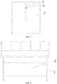
FIG. 1 is a side view diagram of the structure of the invention; -
FIG. 2 is the structural diagram of the diversion pressure plate of the invention; -
FIG. 3 is the structural diagram of the first diversion pressure plate; -
FIG. 4 is a front view diagram of the structure of the invention; -
FIG. 5 is the structural diagram of the rear end of the hull; -
FIG. 6 is the structural diagram of propeller assembly; -
FIG. 7 is the connection diagram of the first hydraulic cylinder and the first diversion pressure plate; - The labels in the above figures are as follows: 1. Guide baffle; 2. First diversion pressure plate; 3. Second diversion pressure plate; 4. Third diversion pressure plate; 5. First hydraulic cylinder; 6. Second hydraulic cylinder; 7. Third hydraulic cylinder; 8. Sliding channel; 9. Sliding block; 10. Sliding rail; 11. Propeller assembly; 12. Vertical sliding plate; 13. Chain; 14. Winding drum; 15. Vertical pipe; 16. Rod.
- In order to make the purpose, technical scheme and advantages of the embodiment of the invention clearer, the technical scheme in the embodiment of the invention will be described clearly and completely in combination with the embodiment of the invention. Obviously, the described embodiment is a part of the embodiment of the invention, rather than a complete embodiment. Based on the embodiment of the invention, all other embodiments obtained by ordinary technicians in the area without extra efforts belong to the scope of protection of the invention.
- Referring to
FIGS. 1-6 , this embodiment provides a hull auxiliary mechanism for reducing the draft of a hull, including aguide baffle 1 on both sides of the hull. The two ends of the guide baffle extend out of the front and rear ends of the hull. The lower end of the diversion pressure plate extends out of the bottom of the hull. The front and rear ends of the hull are flat inclined plates. The bottom of the hull is a flat plate; - First of all, the water flow is guided to the bottom of the hull through the guide baffles on both sides. The front end of the hull is a flat inclined plate. Water rushes through the bottom of the hull against the flat plate. The water flow at the hull bottom is equal to the water flow outside;
- The auxiliary mechanism also includes a water resistance mechanism, which comprises a first
diversion pressure plate 2, a seconddiversion pressure plate 3 and a thirddiversion pressure plate 4; - Among them, the lower end of the first diversion pressure plate is hinged on the inclined plate at the front end of the hull. The first
hydraulic cylinder 5 is arranged in the hull. The rod body of the first hydraulic cylinder passes through the inclined plate at the front end of the hull and is hinged with the upper end of the first diversion pressure plate; - When the rudder blade and thruster in the stern are too shallow, the rudder efficiency will be reduced, the resistance on the bow will be increased and the operation performance will be poor, which will increase the energy consumption of the ship when it is running. Therefore, the first diversion pressure plate is pressed down through the first hydraulic cylinder to adjust the angle of water flow impact, so that the water can flow into the bottom of the hull more smoothly. During the process from vertical impingement to inclined impingement against the first diversion pressure plate, the buoyancy of the first diversion pressure plate increases continuously, which can lift the bow and reduce the draft of the bow.
- The upper end of the first diversion pressure plate is located at the highest draft of the hull, and the upper end of the first diversion pressure plate is always above the water surface.
- The second diversion pressure plate is arranged parallel to the flat plate at the bottom of the hull, and the side close to the front end of the hull is hinged with the flat plate of the hull bottom. The hull is provided with a second
hydraulic cylinder 6, and the rod body of the second hydraulic cylinder is hinged with the other side of the second diversion pressure plate through the flat plate at the bottom of the hull; - The lower end of the third diversion pressure plate is hinged on the inclined plate at the rear end of the hull. The third
hydraulic cylinder 7 is arranged in the hull. The rod body of the third hydraulic cylinder passes through the inclined plate at the rear end of the hull and is hinged with the upper end of the third diversion pressure plate. - The draft of the stern is large, the bow is upwarped and the wind resistance area is increased. Especially when the ship meets cross wind, the bow is greatly affected by the wind, which will offset the rudder effect of the ship. The phenomenon of "rudder searching for wind" is obvious, that is, the ship's maneuverability is poor, and if it is too large, the blind area of the bow will be increased. Therefore, a third diversion pressure plate is added, and the third guide water pressure plate is pressed down, so that the water flows directly through the stern to impact the third diversion pressure plate, just like the first diversion pressure plate;
- At the same time, by adjusting the angle of the second diversion pressure plate, the current strength of the water flow impact is changed, and the buoyancy of the hull bottom is increased. The combination of the first, the second and the third diversion pressure plates with the help of guide baffles and the hull structure can increase the buoyancy of the hull and reduce the draft of the hull;
- More importantly, the first, second and third diversion pressure plates can be adjusted respectively. When the hull requires the draft of the bow to be greater than the draft of the stern, requires the draft of the hull to be rather deep, or requires the draft to be level, the three diversion pressure plates can also complete it.
- The first, the second and the third diversion pressure plates are provided with sliding channels 8, and the sliding blocks 9 are arranged in the sliding channels. The rod body is hinged on the sliding blocks. The length of the sliding channel is the maximum turning angle of the diversion pressure plate and is the length of the sliding block movement.
- Preferably, the auxiliary mechanism also includes a propeller assembly lifting mechanism, specifically including a sliding
rail 10 arranged vertically at the rear end of the hull and a vertical slidingplate 12 arranged on thepropeller assembly 11. The cross section of the sliding rail is concave, and the convex clamping strips are arranged on both sides of the concave inner wall. The two sides of the vertical sliding plate are provided with concave grooves, and the clamping strip is matched with the groove. The propeller assembly is connected to the rewindingdrum 14 on the hull through thechain 13, and the rewinding of the chain is completed through the rewinding drum to control the lifting and lowering of the propeller assembly. - After the first, second and third diversion pressure plates reduce the draft of the hull, the rudder blade and thruster in the stern will be too shallow, the rudder efficiency will be reduced, the resistance on the bow will be increased, the operation performance will be poor, and the energy consumption of the ship will be increased. Therefore, the invention also provides a lifting propulsion mechanism which can be used with the first, second and third diversion pressure plates.
- A number of positioning holes are arranged on the sliding rail. After the position of the propeller assembly is determined, the positioning pin is inserted into the positioning hole to avoid the propeller assembly from moving up. It can avoid the propeller assembly from moving down by controlling the chain.
- At the same time, in the embodiment, a propeller is arranged on both sides of the stern to reduce the impact of the water flow at the hull bottom on the propeller.
- The first hydraulic cylinder, the second hydraulic cylinder and the third hydraulic cylinder are vertically arranged in the hull.
- The hull is provided with three
vertical pipes 15. The upper ends of the three vertical pipes are respectively used to support the first hydraulic cylinder, the second hydraulic cylinder and the third hydraulic cylinder. The rod body passes through the hull through the interior of the vertical pipe. - The upper end of the vertical pipe is higher than the maximum draft of the hull, so as to avoid water flowing into the hull from the upper end of the vertical pipe.
- A short rod is arranged between the rod body of the hydraulic cylinder and the diversion pressure plate. The two ends of the short rod are respectively hinged on the rod body and the diversion water plate. The short rod is used for the angle adjustment between the rod body and the diversion pressure plate.
- In
FIG. 7 , ashort rod 16 is added between the rod body of the firsthydraulic cylinder 5 and the firstdiversion pressure plate 2. - It should be noted that in this paper, relational terms such as first and second are only used to distinguish one entity or operation from another, and do not necessarily require or imply any such actual relationship or order between these entities or operations. Moreover, the terms "include", "comprise" or any other variation thereof are intended to cover non-exclusive inclusion so that a process, method, article, or equipment that includes a series of elements includes not only those elements, but also other elements not explicitly listed, or those inherent to such process, method, article or equipment. In the absence of more restrictions, the statement "include a... "limited element does not preclude the existence of additional identical elements in the process, method, article, or equipment that includes the element.
- In the present invention, characteristics are interleaved with each other and do not necessarily exist independently unless there are clear provisions and limitations. The above display and description include the basic principle, main characteristics and advantages of the invention. The technical personnel engaged in the field should know that the present invention is not limited to the limitation of the embodiments mentioned above. The embodiments and specifications mentioned above are only preferred examples of the present invention, rather than being used to limit the invention, so as to become the only choice. Under the spirit and scope requirements of the invention, the invention can be further changed and optimized. The improvement and optimization of the invention are all within the scope of the invention claimed to be protected. The specific scope of protection required by the invention is defined by the attached claims and their equivalents.
Claims (5)
- A hull auxiliary mechanism for reducing a draft of a hull, comprising:a guide baffle (1) on each side of the hull,two ends of the guide baffle extend out of a front end and a rear end of the hull, a lower end of the guide baffle extends out of a bottom of the hull, the front end of the hull is a first flat inclined plate, and the rear end of the hull is a second flat inclined plate, the bottom of the hull is a flat plate; characterized by a water resistance mechanism, the water resistance mechanism comprises a first diversion pressure plate (2), a second diversion pressure plate (3) and a third diversion pressure plate (4);a lower end of the first diversion pressure plate is hinged on the first flat inclined plate at the front end of the hull, a first hydraulic cylinder (5) is arranged in the hull, a rod body of the first hydraulic cylinder passes through the first flat inclined plate at the front end of the hull and the rod body of the first hydraulic cylinder is hinged to an upper end of the first diversion pressure plate;the second diversion pressure plate is arranged parallel to the flat plate at the bottom of the hull, and a first side of the second diversion pressure plate close to the front end of the hull is hinged with the flat plate at the bottom of the hull, the hull is provided with a second hydraulic cylinder (6), and a rod body of the second hydraulic cylinder is hinged with a second side of the second diversion pressure plate through the flat plate at the bottom of the hull;a lower end of the third diversion pressure plate is hinged on the second flat inclined plate at the rear end of the hull, a third hydraulic cylinder (7) is arranged in the hull, a rod body of the third hydraulic cylinder passes through the second flat inclined plate at the rear end of the hull and the rod body of the third hydraulic cylinder is hinged with an upper end of the third diversion pressure plate.
- The hull auxiliary mechanism according to claim 1, characterized in that: each of the first diversion pressure plate, the second diversion pressure plate and the third diversion pressure plate is provided with a sliding channel (8), a sliding block (9) is arranged in the sliding channel, and each of the rod body of the first hydraulic cylinder, the rod body of the second hydraulic cylinder and the rod body of the third hydraulic cylinder is hinged on the sliding block.
- The hull auxiliary mechanism according to claim 1, characterized in that: the first hydraulic cylinder, the second hydraulic cylinder and the third hydraulic cylinder are vertically arranged in the hull.
- The hull auxiliary mechanism according to claim 3, characterized in that: the hull is provided with three vertical pipes (15), and upper ends of the three vertical pipes are configured to support the first hydraulic cylinder, the second hydraulic cylinder and the third hydraulic cylinder respectively, the rod body of the first hydraulic cylinder, the rod body of the second hydraulic cylinder and the rod body of the third hydraulic cylinder pass through the hull through interiors of the three vertical pipes.
- The hull auxiliary mechanism according to claim 4, characterized in that: each of the upper ends of the three vertical pipes is higher than a maximum draft of the hull.
Applications Claiming Priority (2)
| Application Number | Priority Date | Filing Date | Title |
|---|---|---|---|
| CN201910926801.3A CN110588912B (en) | 2019-09-27 | 2019-09-27 | Hull auxiliary mechanism for reducing draft of hull |
| PCT/CN2019/114008 WO2021056674A1 (en) | 2019-09-27 | 2019-10-29 | Hull assisting mechanism for reducing draft of hull |
Publications (3)
| Publication Number | Publication Date |
|---|---|
| EP3858725A1 EP3858725A1 (en) | 2021-08-04 |
| EP3858725A4 EP3858725A4 (en) | 2022-01-12 |
| EP3858725B1 true EP3858725B1 (en) | 2022-06-08 |
Family
ID=68864281
Family Applications (1)
| Application Number | Title | Priority Date | Filing Date |
|---|---|---|---|
| EP19947192.1A Active EP3858725B1 (en) | 2019-09-27 | 2019-10-29 | Hull assisting mechanism for reducing draft of hull |
Country Status (12)
| Country | Link |
|---|---|
| US (1) | US11613328B2 (en) |
| EP (1) | EP3858725B1 (en) |
| JP (1) | JP7032573B2 (en) |
| KR (1) | KR102413064B1 (en) |
| CN (1) | CN110588912B (en) |
| AU (1) | AU2019467174B2 (en) |
| CA (1) | CA3119218C (en) |
| DK (1) | DK3858725T3 (en) |
| ES (1) | ES2922544T3 (en) |
| PL (1) | PL3858725T3 (en) |
| PT (1) | PT3858725T (en) |
| WO (1) | WO2021056674A1 (en) |
Families Citing this family (2)
| Publication number | Priority date | Publication date | Assignee | Title |
|---|---|---|---|---|
| CN114435568B (en) * | 2022-01-10 | 2023-09-22 | 安徽安华机械科技有限公司 | A swinging wing structure that provides hull buoyancy and a hull with the wing structure |
| CN117345056B (en) * | 2023-10-26 | 2025-09-12 | 一汽解放汽车有限公司 | A control system and method for hydraulic lock of diversion cabin |
Family Cites Families (30)
| Publication number | Priority date | Publication date | Assignee | Title |
|---|---|---|---|---|
| US4953492A (en) * | 1989-06-21 | 1990-09-04 | Fmc Corporation | Water supporting and propulsion systems |
| JPH04114897U (en) * | 1991-03-26 | 1992-10-09 | 石川島播磨重工業株式会社 | Hydrofoil for boat attitude control |
| CN1177557A (en) * | 1996-06-24 | 1998-04-01 | 维德海运有限公司 | Auxiliary ship for assisting approach of ship |
| CN2273676Y (en) * | 1996-09-05 | 1998-02-04 | 周新民 | Side wall type or double body type air-cushion ship wave reducing device |
| US5746146A (en) | 1996-10-18 | 1998-05-05 | Bixel, Jr.; Charles Gilbert | Surface effect planing pontoon seaplane (SEPPS) |
| CA2637207C (en) * | 2005-12-23 | 2013-05-28 | Thomas Wilmot Meyer | High speed watercraft suitable for rough water conditions |
| CN101249873B (en) * | 2008-04-01 | 2010-06-16 | 周洪斌 | Hydrofoil craft having hydroplane function |
| CN101348162A (en) * | 2008-05-21 | 2009-01-21 | 三一电气有限责任公司 | Ship draft adjustment device and transport ship with the device |
| CN101638136B (en) | 2009-08-25 | 2012-05-23 | 中国舰船研究设计中心 | Planing craft with split lift plate arrangement |
| CN101712372B (en) | 2009-09-24 | 2012-04-11 | 深圳市海斯比船艇科技股份有限公司 | Three-controllable hydrofoil planing boat |
| CN201660101U (en) * | 2010-03-19 | 2010-12-01 | 荆春 | A hull drag reduction and booster mechanism |
| JP2015003641A (en) * | 2013-06-21 | 2015-01-08 | 武田 弘 | Ship |
| US8955452B1 (en) * | 2013-11-21 | 2015-02-17 | Harley Wilson | Adjustable planing device for pontoon boats |
| CN203876971U (en) * | 2014-04-24 | 2014-10-15 | 安昭祥 | Side wall type high-speed launch with front-arrangement power propeller |
| CN204110313U (en) * | 2014-09-04 | 2015-01-21 | 罗友明 | A kind of hull bottom reducing the resistance that moves ahead |
| CN205044906U (en) | 2015-02-09 | 2016-02-24 | 缪德贵 | Binary hydrofoil water wing structure |
| CN204606126U (en) * | 2015-05-05 | 2015-09-02 | 中船重工船舶设计研究中心有限公司 | A kind of scalable enclosure device for boats and ships resistance reduction by air cavity system |
| CN104867268A (en) * | 2015-05-11 | 2015-08-26 | 国家电网公司 | Monitoring device and method for judging limit exceeding of moving object under power transmission line |
| CN107640295A (en) * | 2016-07-22 | 2018-01-30 | 张家港市海丰水面环保机械有限公司 | The Multifunctional rinsing boat that topside installation hydraulic pressure mozzle propeller promotes |
| CN206485510U (en) * | 2017-01-20 | 2017-09-12 | 佛山市途达游艇制造有限公司 | Wave suppression plate |
| KR101947260B1 (en) * | 2017-03-23 | 2019-02-12 | 목포해양대학교 산학협력단 | A trim tab apparatus for protecting the bottom of a ship |
| CN107226167B (en) * | 2017-04-19 | 2019-06-28 | 珠海市磐石电子科技有限公司 | Ship |
| CN207314194U (en) * | 2017-10-26 | 2018-05-04 | 国网安徽省电力公司淮南供电公司 | A kind of outdoor non-paved road patrol route signboard erecting device |
| CN108128402B (en) * | 2017-12-06 | 2019-12-13 | 浙江海洋大学 | Ship bottom structure capable of reducing water flow resistance |
| CN208248417U (en) * | 2017-12-07 | 2018-12-18 | 天津海运职业学院 | A kind of ship reducing ship resistance |
| US10745084B2 (en) | 2018-01-10 | 2020-08-18 | Avalon & Tahoe Mfg. Inc. | System and method for enhancing a wake profile for pontoon boats |
| CN208346787U (en) * | 2018-05-31 | 2019-01-08 | 威海维思泰科溢油回收设备有限公司 | Unmanned oil receiving equipment |
| WO2020093134A1 (en) * | 2018-11-07 | 2020-05-14 | Castelli Vottorio Mark | Modular planing multi-hull systems and methods for vessels |
| CN110001871B (en) * | 2019-03-13 | 2020-05-15 | 上海雄程海洋工程股份有限公司 | Control method for automatically adjusting posture of ship body of piling ship |
| CN211568246U (en) * | 2019-09-27 | 2020-09-25 | 唐旭明 | Ship body auxiliary mechanism for reducing ship body draft |
-
2019
- 2019-09-27 CN CN201910926801.3A patent/CN110588912B/en active Active
- 2019-10-29 JP JP2020563775A patent/JP7032573B2/en not_active Expired - Fee Related
- 2019-10-29 ES ES19947192T patent/ES2922544T3/en active Active
- 2019-10-29 DK DK19947192.1T patent/DK3858725T3/en active
- 2019-10-29 US US17/049,582 patent/US11613328B2/en active Active
- 2019-10-29 AU AU2019467174A patent/AU2019467174B2/en active Active
- 2019-10-29 WO PCT/CN2019/114008 patent/WO2021056674A1/en not_active Ceased
- 2019-10-29 CA CA3119218A patent/CA3119218C/en active Active
- 2019-10-29 EP EP19947192.1A patent/EP3858725B1/en active Active
- 2019-10-29 KR KR1020207031528A patent/KR102413064B1/en active Active
- 2019-10-29 PT PT199471921T patent/PT3858725T/en unknown
- 2019-10-29 PL PL19947192.1T patent/PL3858725T3/en unknown
Also Published As
| Publication number | Publication date |
|---|---|
| CN110588912A (en) | 2019-12-20 |
| DK3858725T3 (en) | 2022-07-18 |
| PL3858725T3 (en) | 2023-01-09 |
| JP7032573B2 (en) | 2022-03-08 |
| AU2019467174B2 (en) | 2022-07-21 |
| EP3858725A4 (en) | 2022-01-12 |
| CA3119218A1 (en) | 2021-04-01 |
| KR20210038840A (en) | 2021-04-08 |
| US20220388605A1 (en) | 2022-12-08 |
| ES2922544T3 (en) | 2022-09-16 |
| US11613328B2 (en) | 2023-03-28 |
| EP3858725A1 (en) | 2021-08-04 |
| PT3858725T (en) | 2022-08-01 |
| JP2022503362A (en) | 2022-01-12 |
| WO2021056674A1 (en) | 2021-04-01 |
| AU2019467174A1 (en) | 2021-05-13 |
| KR102413064B1 (en) | 2022-06-24 |
| CA3119218C (en) | 2021-11-02 |
| CN110588912B (en) | 2024-09-03 |
Similar Documents
| Publication | Publication Date | Title |
|---|---|---|
| CA2801273C (en) | Telescopic submarine | |
| CA3119218C (en) | Hull auxiliary mechanism for reducing the draft of a hull | |
| US4074646A (en) | Variable foil keel and sail boat | |
| CN103381877A (en) | Improved tugboat hull and tugboat comprising the improved hull | |
| CN211568246U (en) | Ship body auxiliary mechanism for reducing ship body draft | |
| US20100127150A1 (en) | Outboard Motor Mount | |
| EP2704946B1 (en) | Towing vessel | |
| CN205168822U (en) | Icebreaker bow | |
| CN101311065A (en) | Deep sea submarine | |
| CN211568224U (en) | Self-made hull structure | |
| CN110641612B (en) | Self-made hull structure | |
| ES8507404A1 (en) | Amphibious equipment for hauling ashore and launching of hydrofoil and small coastal crafts | |
| FI82425B (en) | KOELKONSTRUKTION. | |
| RU2788488C1 (en) | Hull auxiliary mechanism to reduce the draft of the ship's hull | |
| US20080087208A1 (en) | Apparatus for protecting the hull of a watercraft | |
| CN110949606B (en) | Combined boat bubble suppression and evacuation device with extendable moon pool | |
| CN110667770B (en) | A trimaran suitable for multi-sea navigation | |
| CN110641668B (en) | A multi-directional adjustment auxiliary structure for a hull propulsion mechanism | |
| CN211468688U (en) | Combined vessel bubble suppression and evacuation device with extendable moonpool | |
| CN211172139U (en) | Combined cutter suction dredger with super-large dredging depth of more than 40 meters | |
| CN222960027U (en) | Dock dredging ship with ship body sliding | |
| CN219886811U (en) | Pile holding frame for steel pipe pile of piling ship | |
| KR20030030467A (en) | Wig with controlling air chamber for improving sea worthiness | |
| CN209956185U (en) | Wave-resistant ship structure | |
| CN107539422A (en) | Water airship |
Legal Events
| Date | Code | Title | Description |
|---|---|---|---|
| STAA | Information on the status of an ep patent application or granted ep patent |
Free format text: STATUS: THE INTERNATIONAL PUBLICATION HAS BEEN MADE |
|
| PUAI | Public reference made under article 153(3) epc to a published international application that has entered the european phase |
Free format text: ORIGINAL CODE: 0009012 |
|
| STAA | Information on the status of an ep patent application or granted ep patent |
Free format text: STATUS: REQUEST FOR EXAMINATION WAS MADE |
|
| 17P | Request for examination filed |
Effective date: 20210426 |
|
| AK | Designated contracting states |
Kind code of ref document: A1 Designated state(s): AL AT BE BG CH CY CZ DE DK EE ES FI FR GB GR HR HU IE IS IT LI LT LU LV MC MK MT NL NO PL PT RO RS SE SI SK SM TR |
|
| A4 | Supplementary search report drawn up and despatched |
Effective date: 20211214 |
|
| RIC1 | Information provided on ipc code assigned before grant |
Ipc: B63B 43/10 20060101AFI20211208BHEP |
|
| GRAP | Despatch of communication of intention to grant a patent |
Free format text: ORIGINAL CODE: EPIDOSNIGR1 |
|
| STAA | Information on the status of an ep patent application or granted ep patent |
Free format text: STATUS: GRANT OF PATENT IS INTENDED |
|
| DAV | Request for validation of the european patent (deleted) | ||
| DAX | Request for extension of the european patent (deleted) | ||
| INTG | Intention to grant announced |
Effective date: 20220322 |
|
| GRAS | Grant fee paid |
Free format text: ORIGINAL CODE: EPIDOSNIGR3 |
|
| GRAA | (expected) grant |
Free format text: ORIGINAL CODE: 0009210 |
|
| STAA | Information on the status of an ep patent application or granted ep patent |
Free format text: STATUS: THE PATENT HAS BEEN GRANTED |
|
| AK | Designated contracting states |
Kind code of ref document: B1 Designated state(s): AL AT BE BG CH CY CZ DE DK EE ES FI FR GB GR HR HU IE IS IT LI LT LU LV MC MK MT NL NO PL PT RO RS SE SI SK SM TR |
|
| REG | Reference to a national code |
Ref country code: AT Ref legal event code: REF Ref document number: 1496769 Country of ref document: AT Kind code of ref document: T Effective date: 20220615 Ref country code: CH Ref legal event code: EP |
|
| REG | Reference to a national code |
Ref country code: DE Ref legal event code: R096 Ref document number: 602019015784 Country of ref document: DE |
|
| REG | Reference to a national code |
Ref country code: IE Ref legal event code: FG4D |
|
| REG | Reference to a national code |
Ref country code: DK Ref legal event code: T3 Effective date: 20220715 |
|
| REG | Reference to a national code |
Ref country code: RO Ref legal event code: EPE |
|
| REG | Reference to a national code |
Ref country code: FI Ref legal event code: FGE |
|
| REG | Reference to a national code |
Ref country code: PT Ref legal event code: SC4A Ref document number: 3858725 Country of ref document: PT Date of ref document: 20220801 Kind code of ref document: T Free format text: AVAILABILITY OF NATIONAL TRANSLATION Effective date: 20220727 |
|
| REG | Reference to a national code |
Ref country code: NL Ref legal event code: FP |
|
| REG | Reference to a national code |
Ref country code: SE Ref legal event code: TRGR |
|
| REG | Reference to a national code |
Ref country code: NO Ref legal event code: T2 Effective date: 20220608 |
|
| REG | Reference to a national code |
Ref country code: ES Ref legal event code: FG2A Ref document number: 2922544 Country of ref document: ES Kind code of ref document: T3 Effective date: 20220916 |
|
| REG | Reference to a national code |
Ref country code: LT Ref legal event code: MG9D |
|
| REG | Reference to a national code |
Ref country code: GR Ref legal event code: EP Ref document number: 20220401511 Country of ref document: GR Effective date: 20221010 |
|
| PG25 | Lapsed in a contracting state [announced via postgrant information from national office to epo] |
Ref country code: LT Free format text: LAPSE BECAUSE OF FAILURE TO SUBMIT A TRANSLATION OF THE DESCRIPTION OR TO PAY THE FEE WITHIN THE PRESCRIBED TIME-LIMIT Effective date: 20220608 Ref country code: HR Free format text: LAPSE BECAUSE OF FAILURE TO SUBMIT A TRANSLATION OF THE DESCRIPTION OR TO PAY THE FEE WITHIN THE PRESCRIBED TIME-LIMIT Effective date: 20220608 Ref country code: BG Free format text: LAPSE BECAUSE OF FAILURE TO SUBMIT A TRANSLATION OF THE DESCRIPTION OR TO PAY THE FEE WITHIN THE PRESCRIBED TIME-LIMIT Effective date: 20220908 |
|
| REG | Reference to a national code |
Ref country code: AT Ref legal event code: MK05 Ref document number: 1496769 Country of ref document: AT Kind code of ref document: T Effective date: 20220608 |
|
| PG25 | Lapsed in a contracting state [announced via postgrant information from national office to epo] |
Ref country code: RS Free format text: LAPSE BECAUSE OF FAILURE TO SUBMIT A TRANSLATION OF THE DESCRIPTION OR TO PAY THE FEE WITHIN THE PRESCRIBED TIME-LIMIT Effective date: 20220608 Ref country code: LV Free format text: LAPSE BECAUSE OF FAILURE TO SUBMIT A TRANSLATION OF THE DESCRIPTION OR TO PAY THE FEE WITHIN THE PRESCRIBED TIME-LIMIT Effective date: 20220608 |
|
| PG25 | Lapsed in a contracting state [announced via postgrant information from national office to epo] |
Ref country code: SM Free format text: LAPSE BECAUSE OF FAILURE TO SUBMIT A TRANSLATION OF THE DESCRIPTION OR TO PAY THE FEE WITHIN THE PRESCRIBED TIME-LIMIT Effective date: 20220608 Ref country code: SK Free format text: LAPSE BECAUSE OF FAILURE TO SUBMIT A TRANSLATION OF THE DESCRIPTION OR TO PAY THE FEE WITHIN THE PRESCRIBED TIME-LIMIT Effective date: 20220608 Ref country code: EE Free format text: LAPSE BECAUSE OF FAILURE TO SUBMIT A TRANSLATION OF THE DESCRIPTION OR TO PAY THE FEE WITHIN THE PRESCRIBED TIME-LIMIT Effective date: 20220608 Ref country code: CZ Free format text: LAPSE BECAUSE OF FAILURE TO SUBMIT A TRANSLATION OF THE DESCRIPTION OR TO PAY THE FEE WITHIN THE PRESCRIBED TIME-LIMIT Effective date: 20220608 Ref country code: AT Free format text: LAPSE BECAUSE OF FAILURE TO SUBMIT A TRANSLATION OF THE DESCRIPTION OR TO PAY THE FEE WITHIN THE PRESCRIBED TIME-LIMIT Effective date: 20220608 |
|
| PG25 | Lapsed in a contracting state [announced via postgrant information from national office to epo] |
Ref country code: IS Free format text: LAPSE BECAUSE OF FAILURE TO SUBMIT A TRANSLATION OF THE DESCRIPTION OR TO PAY THE FEE WITHIN THE PRESCRIBED TIME-LIMIT Effective date: 20221008 |
|
| REG | Reference to a national code |
Ref country code: DE Ref legal event code: R097 Ref document number: 602019015784 Country of ref document: DE |
|
| PG25 | Lapsed in a contracting state [announced via postgrant information from national office to epo] |
Ref country code: AL Free format text: LAPSE BECAUSE OF FAILURE TO SUBMIT A TRANSLATION OF THE DESCRIPTION OR TO PAY THE FEE WITHIN THE PRESCRIBED TIME-LIMIT Effective date: 20220608 |
|
| PLBE | No opposition filed within time limit |
Free format text: ORIGINAL CODE: 0009261 |
|
| STAA | Information on the status of an ep patent application or granted ep patent |
Free format text: STATUS: NO OPPOSITION FILED WITHIN TIME LIMIT |
|
| 26N | No opposition filed |
Effective date: 20230310 |
|
| PG25 | Lapsed in a contracting state [announced via postgrant information from national office to epo] |
Ref country code: MC Free format text: LAPSE BECAUSE OF FAILURE TO SUBMIT A TRANSLATION OF THE DESCRIPTION OR TO PAY THE FEE WITHIN THE PRESCRIBED TIME-LIMIT Effective date: 20220608 |
|
| REG | Reference to a national code |
Ref country code: CH Ref legal event code: PL |
|
| PG25 | Lapsed in a contracting state [announced via postgrant information from national office to epo] |
Ref country code: LU Free format text: LAPSE BECAUSE OF NON-PAYMENT OF DUE FEES Effective date: 20221029 |
|
| PG25 | Lapsed in a contracting state [announced via postgrant information from national office to epo] |
Ref country code: LI Free format text: LAPSE BECAUSE OF NON-PAYMENT OF DUE FEES Effective date: 20221031 Ref country code: CH Free format text: LAPSE BECAUSE OF NON-PAYMENT OF DUE FEES Effective date: 20221031 |
|
| PG25 | Lapsed in a contracting state [announced via postgrant information from national office to epo] |
Ref country code: CY Free format text: LAPSE BECAUSE OF FAILURE TO SUBMIT A TRANSLATION OF THE DESCRIPTION OR TO PAY THE FEE WITHIN THE PRESCRIBED TIME-LIMIT Effective date: 20220608 |
|
| PG25 | Lapsed in a contracting state [announced via postgrant information from national office to epo] |
Ref country code: MK Free format text: LAPSE BECAUSE OF FAILURE TO SUBMIT A TRANSLATION OF THE DESCRIPTION OR TO PAY THE FEE WITHIN THE PRESCRIBED TIME-LIMIT Effective date: 20220608 Ref country code: HU Free format text: LAPSE BECAUSE OF FAILURE TO SUBMIT A TRANSLATION OF THE DESCRIPTION OR TO PAY THE FEE WITHIN THE PRESCRIBED TIME-LIMIT; INVALID AB INITIO Effective date: 20191029 |
|
| PG25 | Lapsed in a contracting state [announced via postgrant information from national office to epo] |
Ref country code: MT Free format text: LAPSE BECAUSE OF FAILURE TO SUBMIT A TRANSLATION OF THE DESCRIPTION OR TO PAY THE FEE WITHIN THE PRESCRIBED TIME-LIMIT Effective date: 20220608 |
|
| PG25 | Lapsed in a contracting state [announced via postgrant information from national office to epo] |
Ref country code: BG Free format text: LAPSE BECAUSE OF FAILURE TO SUBMIT A TRANSLATION OF THE DESCRIPTION OR TO PAY THE FEE WITHIN THE PRESCRIBED TIME-LIMIT Effective date: 20220608 |
|
| PG25 | Lapsed in a contracting state [announced via postgrant information from national office to epo] |
Ref country code: BG Free format text: LAPSE BECAUSE OF FAILURE TO SUBMIT A TRANSLATION OF THE DESCRIPTION OR TO PAY THE FEE WITHIN THE PRESCRIBED TIME-LIMIT Effective date: 20220608 |
|
| PGFP | Annual fee paid to national office [announced via postgrant information from national office to epo] |
Ref country code: GR Payment date: 20250911 Year of fee payment: 7 |
|
| PGFP | Annual fee paid to national office [announced via postgrant information from national office to epo] |
Ref country code: NL Payment date: 20250912 Year of fee payment: 7 Ref country code: PL Payment date: 20250812 Year of fee payment: 7 Ref country code: IT Payment date: 20250922 Year of fee payment: 7 |
|
| PGFP | Annual fee paid to national office [announced via postgrant information from national office to epo] |
Ref country code: BE Payment date: 20250917 Year of fee payment: 7 Ref country code: GB Payment date: 20250904 Year of fee payment: 7 |
|
| PGFP | Annual fee paid to national office [announced via postgrant information from national office to epo] |
Ref country code: FR Payment date: 20250908 Year of fee payment: 7 |
|
| PGFP | Annual fee paid to national office [announced via postgrant information from national office to epo] |
Ref country code: SE Payment date: 20250910 Year of fee payment: 7 |
|
| PGFP | Annual fee paid to national office [announced via postgrant information from national office to epo] |
Ref country code: IE Payment date: 20250909 Year of fee payment: 7 |
|
| PGFP | Annual fee paid to national office [announced via postgrant information from national office to epo] |
Ref country code: RO Payment date: 20250929 Year of fee payment: 7 |
|
| PGFP | Annual fee paid to national office [announced via postgrant information from national office to epo] |
Ref country code: PT Payment date: 20251016 Year of fee payment: 7 |
|
| PGFP | Annual fee paid to national office [announced via postgrant information from national office to epo] |
Ref country code: DE Payment date: 20250902 Year of fee payment: 7 |
|
| PGFP | Annual fee paid to national office [announced via postgrant information from national office to epo] |
Ref country code: NO Payment date: 20251009 Year of fee payment: 7 |
|
| PGFP | Annual fee paid to national office [announced via postgrant information from national office to epo] |
Ref country code: FI Payment date: 20251014 Year of fee payment: 7 Ref country code: DK Payment date: 20251014 Year of fee payment: 7 |
|
| PGFP | Annual fee paid to national office [announced via postgrant information from national office to epo] |
Ref country code: TR Payment date: 20251017 Year of fee payment: 7 |
|
| PGFP | Annual fee paid to national office [announced via postgrant information from national office to epo] |
Ref country code: ES Payment date: 20251107 Year of fee payment: 7 |
|
| PG25 | Lapsed in a contracting state [announced via postgrant information from national office to epo] |
Ref country code: SI Free format text: LAPSE BECAUSE OF FAILURE TO SUBMIT A TRANSLATION OF THE DESCRIPTION OR TO PAY THE FEE WITHIN THE PRESCRIBED TIME-LIMIT Effective date: 20220608 |