EP3858686A1 - Folding wheel chock for industrial and/or commercial vehicles - Google Patents
Folding wheel chock for industrial and/or commercial vehicles Download PDFInfo
- Publication number
- EP3858686A1 EP3858686A1 EP21153055.5A EP21153055A EP3858686A1 EP 3858686 A1 EP3858686 A1 EP 3858686A1 EP 21153055 A EP21153055 A EP 21153055A EP 3858686 A1 EP3858686 A1 EP 3858686A1
- Authority
- EP
- European Patent Office
- Prior art keywords
- stop ramp
- support wall
- stop
- wheel chock
- tip
- Prior art date
- Legal status (The legal status is an assumption and is not a legal conclusion. Google has not performed a legal analysis and makes no representation as to the accuracy of the status listed.)
- Granted
Links
Images


Classifications
-
- B—PERFORMING OPERATIONS; TRANSPORTING
- B60—VEHICLES IN GENERAL
- B60P—VEHICLES ADAPTED FOR LOAD TRANSPORTATION OR TO TRANSPORT, TO CARRY, OR TO COMPRISE SPECIAL LOADS OR OBJECTS
- B60P3/00—Vehicles adapted to transport, to carry or to comprise special loads or objects
- B60P3/06—Vehicles adapted to transport, to carry or to comprise special loads or objects for carrying vehicles
- B60P3/07—Vehicles adapted to transport, to carry or to comprise special loads or objects for carrying vehicles for carrying road vehicles
- B60P3/073—Vehicle retainers
- B60P3/075—Vehicle retainers for wheels, hubs, or axle shafts
- B60P3/077—Wheel cradles, chocks, or wells
-
- B—PERFORMING OPERATIONS; TRANSPORTING
- B60—VEHICLES IN GENERAL
- B60T—VEHICLE BRAKE CONTROL SYSTEMS OR PARTS THEREOF; BRAKE CONTROL SYSTEMS OR PARTS THEREOF, IN GENERAL; ARRANGEMENT OF BRAKING ELEMENTS ON VEHICLES IN GENERAL; PORTABLE DEVICES FOR PREVENTING UNWANTED MOVEMENT OF VEHICLES; VEHICLE MODIFICATIONS TO FACILITATE COOLING OF BRAKES
- B60T3/00—Portable devices for preventing unwanted movement of vehicles, e.g. chocks
-
- B—PERFORMING OPERATIONS; TRANSPORTING
- B65—CONVEYING; PACKING; STORING; HANDLING THIN OR FILAMENTARY MATERIAL
- B65G—TRANSPORT OR STORAGE DEVICES, e.g. CONVEYORS FOR LOADING OR TIPPING, SHOP CONVEYOR SYSTEMS OR PNEUMATIC TUBE CONVEYORS
- B65G69/00—Auxiliary measures taken, or devices used, in connection with loading or unloading
- B65G69/003—Restraining movement of a vehicle at a loading station using means not being part of the vehicle
- B65G69/005—Restraining movement of a vehicle at a loading station using means not being part of the vehicle the means engaging at least one wheel of the vehicle
-
- B—PERFORMING OPERATIONS; TRANSPORTING
- B60—VEHICLES IN GENERAL
- B60Y—INDEXING SCHEME RELATING TO ASPECTS CROSS-CUTTING VEHICLE TECHNOLOGY
- B60Y2200/00—Type of vehicle
- B60Y2200/10—Road Vehicles
- B60Y2200/14—Trucks; Load vehicles, Busses
- B60Y2200/147—Trailers, e.g. full trailers or caravans
-
- B—PERFORMING OPERATIONS; TRANSPORTING
- B60—VEHICLES IN GENERAL
- B60Y—INDEXING SCHEME RELATING TO ASPECTS CROSS-CUTTING VEHICLE TECHNOLOGY
- B60Y2200/00—Type of vehicle
- B60Y2200/10—Road Vehicles
- B60Y2200/15—Fork lift trucks, Industrial trucks
Definitions
- the present invention relates to a folding wheel chock for vehicles, in particular for industrial and/or commercial vehicles.
- wheel chocks i.e., wheel wedges, which are placed at the wheels of the vehicle and/or the trailer, to prevent any movement, e.g., due to the presence of even a slight slope, are frequently used, in the transport sector.
- wheel chocks are components subject to high mechanical stress because they must withstand heavy loads of several tons and are normally exposed to the action of atmospheric elements.
- chocks are not normally kept in the driver's cab of the vehicle and, on the contrary, are placed on the trailer, in a substantially vertical position, at least partially housed in special structures, called chock racks, usually fixed to the frame of the vehicle.
- the chocks which are provided in pairs on each vehicle, must thus be both light-weight and strong. They must be light-weight because they are handled continuously by drivers and therefore must meet ergonomic criteria.
- the chocks may have considerable overall dimensions and, therefore, cannot be housed inside the vehicle cab, but as mentioned, are placed in special external chock racks, usually in a vertical position.
- the exterior positioning has further disadvantages.
- the chock is continually subjected to the action of exterior atmospheric elements, which accelerate the aging thereof and therefore the related replacement, and on the other hand, the chocks are often stolen (because they are easy to remove).
- the need is felt to provide a wheel chock that, on the one hand, is strong, reliable, and durable and, on the other hand, has reduced dimensions so that it can also be housed in the cab (when not in use), without increasing the cost and weight.
- reference numeral 4 diagrammatically indicates, as a whole, a wheel chock or wedge for trucks or similar commercial and/or industrial vehicles, according to the present invention.
- the wheel chock 4 comprising a stop ramp 8 having a front face 12 shaped to be interfaced with a vehicle wheel, extending from a first support base 16 to a first vertex 20.
- the front face 12 may be flat or may also have a concave pattern to facilitate the blocking of the associated vehicle wheel resting on it.
- the wheel chock 4 further comprises a support wall 24, extending from a second support base 28 to a second vertex 32.
- the stop ramp 8 and the support wall 24 are hinged by at least one pivot pin 36 at the respective first and second vertexes 20,32, so that they can rotate between a configuration of use, in which the stop ramp 8 and the support wall 24 form a wedge or bridge-shaped structure tapering towards the pivot pin 36, and a non-use or resting configuration in which the stop ramp 8 and the support wall 24 are arranged mutually parallel.
- the stop ramp 8 and the support wall 24 can rotate about the pivot pin to assume two configurations; in the working or use configuration, the wheel chock assumes the larger configuration in which it is arranged in a "V" or bridge shape with the first and second support bases 16,28 on the ground and the pivot pin 36 on the opposite side.
- the stop ramp 8 forms an inclined surface, which opposes the advancement or climbing of a vehicle wheel, by virtue of a wedge effect.
- the stop ramp 8 and the support wall 24 can be mutually rotated so that they are arranged mutually parallel.
- Such a configuration is also the configuration of the minimum dimension and allows the wheel chock 4 to be stored in a special chock rack or even inside the vehicle cab.
- the support wall 24 has at least one abutment 40 shaped to create a limit stop and a support against a corresponding stop 44 of the stop ramp 8, opposite to said front face 12 of the stop ramp 8 itself.
- the stop 44 is located on a rear face 48 of the stop ramp, opposite to the front face 12. Said rear face 48 is directly facing the bearing surface or ground of the wheel chock 4.
- the abutment 40 of the support wall 24 is preferably arranged on an upper edge 52 of the support wall 24 opposite to the second support base 28.
- the abutment 40 and the stop 44 are mutually counter-shaped; they preferably comprise flat surfaces, which are parallel to each other in a mutual contact configuration.
- the stop ramp 8 and/or the support wall 24 are mechanically connected to each other exclusively at the respective first and second apexes 20,32, by means of said pivot pin 36, to be free from mechanical connections on the side of the support bases 16,28.
- the abutment 40 is located below the pivot pin 36, on the side of the respective support bases 16,28.
- the stop 44 on the stop ramp 8 is shaped to offload, through the abutment 40, the thrust it receives from the wheel on the second support base 28.
- the vehicle wheel resting on the front face 12 of the stop ramp 8 applies a thrust which is transmitted the contact between the stop 44 and the abutment 40.
- a contact is offloaded on the second support base 28 and tends to maintain the bridge configuration of the wheel chock 4.
- the thrust on the second support base 28 blocks the support wall 24 in place, which does not tend to spread apart with respect to the stop ramp 8.
- the stop ramp 8 is blocked in place by the load itself applied by the wheel of the vehicle being supported; this load is partially transmitted to the support wall 24 by virtue of the contact between the stop 44 and the abutment 40.
- the load transmitted in this manner strengthens and digs the second support base 28 onto the ground, also by virtue of the respective fastening element 56.
- each element of the wheel chock 4 is blocked in place and no further mechanical connection elements (such as plates, cables, or tie-rods) are required between the stop ramp 8 and the support wall 24, other than the pivot pin 36.
- the second support base 28 comprises a fastening element 56 to the ground, which protrudes at least partially from the second support base 28 to promote the blocking of the support wall 24 to the ground, and thus of the wheel chock 4 itself.
- the first support base 16 comprises a fastening element 56 to the ground, which protrudes at least partially from the first support base 16 to promote the blocking of the stop ramp 8 to the ground.
- Said fasteners 56 may be in one piece with respective first and second support bases 16,28.
- Said fasteners 56 may be connected to and integrally associated with the respective first and second support bases 16,28.
- the term "connected” means that the plate or fastener can be, for example, welded, screwed, embedded, riveted to the respective support base.
- the fasteners 56 are metal material plates. In this manner, it is possible to employ a different material from that of the stop ramp 8 and the support wall 24 which may be more suited for the purpose of blocking the respective support bases 16,28 to the ground.
- the stop ramp 8 has a rib structure 60, alternating with recesses 64, along a transverse direction T-T parallel to the pivot pin 36.
- the stop ramp 8 comprises at least one reinforcing crosspiece 68, arranged parallel to said transverse direction T-T, connecting said ribs 60 with one another.
- reinforcing crosspieces 68 which are inclined or oblique with respect to said transverse direction T-T.
- the support wall 24 has a rib structure 60, alternating with recesses 64, along a transverse direction T-T parallel to the pivot pin 36.
- the support wall 24 comprises at least one reinforcing crosspiece 68, arranged parallel to said transverse direction T-T, connecting said ribs 60 with one another.
- reinforcing crosspieces 68 which are inclined or oblique with respect to said transverse direction T-T.
- the ribs 60 and the recesses 64 of the stop ramp 8 and the support wall 24 are transversely and mutually offset to allow the insertion of the ribs 60 of the stop ramp 8 into the recesses 64 of the support wall 24, in a wheel chock closing configuration 4 in which the stop ramp 8 and the support wall 24 are folded mutually parallel.
- the ribs 60 of the stop ramp 8 at least partially penetrate the recesses 64 of the support wall and vice versa: in this manner, it is possible to compact the wheel chock 4 as much as possible in a closed configuration, since the stop ramp 8 and the support wall 24 at least partially penetrate each other.
- the wheel chock 4 comprises a tip 72 which acts as a first interface portion with the motor vehicle wheel.
- First interface portion means that it is the first portion of the wheel chock 4 that is interfaced with the motor vehicle wheel when in use.
- the advancing wheel initially crushes at least partially said tip 72 before resting stably against the front face 12 of the stop ramp 8.
- a block is automatically created that prevents the accidental displacement and/or closing of the stop ramp itself, since the wheel itself, by its own weight, blocks the wheel chock in place on the ground.
- said tip 72 is associated with the stop ramp 8 at the first support base 16 thereof and is movable from an extracted or working configuration, in which it protrudes towards the associable wheel as an extension of the stop ramp, on the side opposite to the support wall 24, to a retracted or resting configuration in which it is arranged at least partially folded or aligned on the stop ramp 8 and/or the support wall 24.
- said tip 72 is an element made of a flexible material and at least partially foldable around the stop ramp 8 and/or the support wall 24, e.g. as shown in figures 5-8 .
- said tip 72 may be made of polymer, plastic, and similar materials adapted to allow the bending/curving of said tip.
- the tip 72 of a rigid or semi-rigid material, e.g. plastic and/or metal.
- the tip 72 is at least partially retractable within a relative seat of the stop ramp 8.
- the tip 72 is hinged to the stop ramp 8 at the first support base 16 thereof.
- the tip 72 is hinged to the stop ramp 8 by means of a second pivot pin 76 parallel to said pivot pin 36, configured to allow the tip 72 to be folded onto the stop ramp 8 from the side of the front face 12 of the stop ramp 8 ( figures 1-4 , 9-16 ).
- the tip 72 has a rib structure 60, alternating with recesses 64, along a transverse direction parallel to the pivot pin 36.
- the ribs 60 and the recesses 64 of the stop ramp 44 and the tip 72 are transversely and mutually offset to allow the ribs 60 of the stop ramp 44 to be inserted into the recesses 64 of the tip 72, in a wheel chock closing configuration 4 in which the tip 72 is folded over the stop ramp 8 from the side of the front face 12 thereof, and wherein the support wall 24 is folded over the stop ramp 8 from the side of the lower or rear face 48 thereof, opposite to the front face 12 thereof.
- the support wall 24, at the second apex 32 has a plurality of reinforcing ribs 84 at the pivot pin 36, said reinforcing ribs 84 extending along a prevalent longitudinal direction L-L, parallel to the support wall 24 and perpendicular to the pivot pin 36.
- the materials of the wheel chocks 4 described above may be various; preferably, but not exclusively, the stop ramp 8 and/or the support wall 24 are made of a plastic material.
- the stop ramp 8 and the support wall 24 are provided with blocking means 88 which comprise at least one peg 92 adapted to be interfaced with a respective seat 96 (at least partially counter-shaped with respect to the peg 92).
- said closing means 88 are arranged along an edge or side wall 100 of the stop ramp 8 and the support wall 24 to align and mutually interpenetrate when the wheel chock 4 is positioned in a closed or resting configuration. Indeed, in such a resting configuration, the respective side walls 100 of the stop ramp 8 and the support wall 24 are mutually aligned to allow positive coupling, i.e. the insertion of the peg 92 into the respective seat 96.
- the peg 92 and the seat 96 are associated one with the stop ramp 8 and the other with the support wall 24 or vice versa. It is sufficient for the blocking means 88 to comprise a single pair of a peg 92 and a seat 96, at a single side wall 100, but more may also be provided.
- the wheel chock 4 can be stored without the risk of it accidentally "opening".
- the wheel chock when not in use, may be stored in a folded configuration, i.e. with the stop ramp 8 and the support wall 24 arranged in contact, parallel to each other.
- the tip if provided, will be arranged, in turn, parallel to the stop ramp.
- the wheel chock 4 assumes a flat, particularly compact configuration and may, for example, be stored inside the vehicle cab.
- the wheel chock 4 in general, in the folded or resting configuration, has a dimension equal to about half of its size in the in-use configuration.
- the wheel chock can be "opened” by arranging the stop ramp 8 and the support wall 24 in a working configuration, i.e. in a wedge shape, until the abutment 40 of the support wall 24 and the stop 44 of the stop ramp 8 are in mutual contact.
- the wheel chock 4 is now operational. If the wheel of the vehicle approaches the stop ramp 8, the weight of the wheel itself blocks the stop ramp 8 (possibly provided with its own fastening element 56) in place.
- the weight of the wheel is at least partially offloaded onto the support wall 24 through the interfacing between the stop 44 of the stop ramp 8 and the abutment 40 of the support wall 24.
- the support wall 24 is, in turn, anchored to the ground by virtue of its own fastening element 56.
- this configuration does not require further mechanical connection elements (e.g. such as plates, cables, or tie-rods) are required between the stop ramp 8 and the support wall 24, other than the pivot pin 36.
- the wheel chocks according to the invention allow to overcome the drawbacks presented in the prior art.
- the present invention allows to provide a wheel chock, which is mechanically strong and durable.
- the chock has no greater cost or weight than the equivalent "fixed", i.e., non-folding, solutions of the prior art and, at the same time, is lighter and less expensive than known folding solutions.
- the wheel chock according to the present invention in a folded configuration has a significantly reduced volume and can thus also be easily stored inside the cab or passenger compartment of the vehicle.
- the wheel chock of the present invention has a particularly low weight, also by virtue of the fact that it is completely free from the base, i.e. of the ground connection element between the ramp (which is abuttingly interfaced with the tire) and the back or rear surface.
- the geometric structure with ribs ensures that the wheel chock meets the requirements and demands for strength and mechanical resistance.
- the wheel chock of the present invention in a closed or folded configuration, has a particularly compact structure, which can be easily stored inside the cab of the vehicle. This prevents the wheel chock from being subjected to the elements when not in use (increasing the actual life thereof) and from being removed by third parties.
Landscapes
- Engineering & Computer Science (AREA)
- Mechanical Engineering (AREA)
- Transportation (AREA)
- Health & Medical Sciences (AREA)
- Public Health (AREA)
- Body Structure For Vehicles (AREA)
- Auxiliary Methods And Devices For Loading And Unloading (AREA)
- Refuge Islands, Traffic Blockers, Or Guard Fence (AREA)
- Vehicle Step Arrangements And Article Storage (AREA)
Abstract
Description
- The present invention relates to a folding wheel chock for vehicles, in particular for industrial and/or commercial vehicles.
- It is known that wheel chocks, i.e., wheel wedges, which are placed at the wheels of the vehicle and/or the trailer, to prevent any movement, e.g., due to the presence of even a slight slope, are frequently used, in the transport sector.
- Therefore, wheel chocks are components subject to high mechanical stress because they must withstand heavy loads of several tons and are normally exposed to the action of atmospheric elements.
- Indeed, the chocks are not normally kept in the driver's cab of the vehicle and, on the contrary, are placed on the trailer, in a substantially vertical position, at least partially housed in special structures, called chock racks, usually fixed to the frame of the vehicle.
- The chocks, which are provided in pairs on each vehicle, must thus be both light-weight and strong. They must be light-weight because they are handled continuously by drivers and therefore must meet ergonomic criteria.
- At the same time, they must be strong because any risk of accidental breakage, even under full load, must be avoided since there would be a risk of unintentional movements of the vehicle and/or the respective trailer.
- Obviously, these two requirements are antithetical, because it is necessary to limit the resistant sections, the thicknesses, and the connections/walls between the support elements to reduce the weight while, conversely, it is necessary to increase them to increase the strength. Last but not least, the chocks must be affordable.
- Various plastic chocks solutions have been developed art by injection molding in the prior art to achieve the aforesaid advantages.
- In this manner, cost-effective and sufficiently light-weight solutions are obtained, but often at the expense of mechanical strength and, above all, durability.
- Indeed, even if, on one hand, the known solutions made of plastic material can satisfy the type-approval criteria required for these devices, on the other hand, also because of the unfavorable environmental conditions both of work and preservation of the chocks, they rapidly lose their mechanical properties and tend to deteriorate prematurely.
- Furthermore, there is an undisputed technical problem related to the overall dimensions of the chock, because especially for large-diameter wheels, the chocks may have considerable overall dimensions and, therefore, cannot be housed inside the vehicle cab, but as mentioned, are placed in special external chock racks, usually in a vertical position.
- The exterior positioning has further disadvantages. On the one hand, the chock is continually subjected to the action of exterior atmospheric elements, which accelerate the aging thereof and therefore the related replacement, and on the other hand, the chocks are often stolen (because they are easy to remove).
- Solutions of at least partially folding chocks have been made in the prior art to reduce the dimensions of the chocks when they are not in use. Such solutions provide the presence of movable parts that may be at least partially folded on the body of the chock to reduce the overall dimensions in rest condition, flattening the shape as much as possible with respect to the operational configuration of the chock.
- These known solutions are not particularly reliable and durable because, as mentioned, the wheel chock is highly biased in use and the presence of movable parts weakens the mechanical strength thereof unless thickeners and reinforcements are introduced that would, however, increase the weight and cost compared to known solutions of the "fixed" or non-folding type.
- Such cost and weight increases are not acceptable in the commercial vehicle equipment sector.
- The need is therefore felt to solve the drawbacks and limitations mentioned above with reference to the prior art.
- In particular, the need is felt to provide a wheel chock that, on the one hand, is strong, reliable, and durable and, on the other hand, has reduced dimensions so that it can also be housed in the cab (when not in use), without increasing the cost and weight.
- This need is met by a wheel chock according to claim 1.
- Further features and advantages of the present invention will be more comprehensible from the following description of preferred embodiments given by way of non-limiting examples, in which:
-
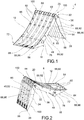
figure 1 depicts a front perspective view of a wheel chock according to an embodiment of the present invention in open or working configuration; -
figure 2 depicts a rear perspective view of the wheel chock infigure 1 , in an open or working configuration; -
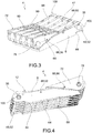
figure 3 depicts a front perspective view of the wheel chock infigure 1 in a closed or resting configuration; -
figure 4 depicts a rear perspective view of the wheel chock infigure 1 , in a closed or resting configuration; -
figure 5 depicts a front perspective view of a wheel chock according to a further embodiment of the present invention in an open or working configuration; -
figure 6 depicts a rear perspective view of the wheel chock infigure 5 , in an open or working configuration; -
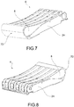
figure 7 depicts a front perspective view of the wheel chock infigure 5 in a closed or resting configuration; -
figure 8 depicts a rear perspective view of the wheel chock infigure 5 , in a closed or resting configuration; -
figure 9 depicts a front perspective view of a wheel chock according to a further embodiment of the present invention in an open or working configuration; -
figure 10 depicts a rear perspective view of the wheel chock infigure 9 , in an open or working configuration; -
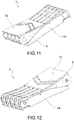
figure 11 depicts a front perspective view of the wheel chock infigure 9 in a closed or resting configuration; -
figure 12 depicts a rear perspective view of the wheel chock infigure 9 , in a closed or resting configuration; -
figure 13 depicts a front perspective view of a wheel chock according to a further embodiment of the present invention in an open or working configuration; -
figure 14 depicts a rear perspective view of the wheel chock infigure 13 , in an open or working configuration; -
figure 15 depicts a front perspective view of the wheel chock infigure 13 in a closed or resting configuration; -
figure 16 depicts a rear perspective view of the wheel chock infigure 13 , in a closed or resting configuration. - Elements or parts in common to the embodiments described will be indicated hereafter using the same reference numerals.
- With reference to the aforementioned figures,
reference numeral 4 diagrammatically indicates, as a whole, a wheel chock or wedge for trucks or similar commercial and/or industrial vehicles, according to the present invention. - The
wheel chock 4 comprising astop ramp 8 having afront face 12 shaped to be interfaced with a vehicle wheel, extending from afirst support base 16 to afirst vertex 20. - The
front face 12 may be flat or may also have a concave pattern to facilitate the blocking of the associated vehicle wheel resting on it. - The
wheel chock 4 further comprises asupport wall 24, extending from asecond support base 28 to asecond vertex 32. - The
stop ramp 8 and thesupport wall 24 are hinged by at least onepivot pin 36 at the respective first andsecond vertexes support wall 24 form a wedge or bridge-shaped structure tapering towards thepivot pin 36, and a non-use or resting configuration in which thestop ramp 8 and thesupport wall 24 are arranged mutually parallel. - In other words, the
stop ramp 8 and thesupport wall 24 can rotate about the pivot pin to assume two configurations; in the working or use configuration, the wheel chock assumes the larger configuration in which it is arranged in a "V" or bridge shape with the first andsecond support bases pivot pin 36 on the opposite side. In such a configuration, thestop ramp 8 forms an inclined surface, which opposes the advancement or climbing of a vehicle wheel, by virtue of a wedge effect. In contrast, in the resting configuration, thestop ramp 8 and thesupport wall 24 can be mutually rotated so that they are arranged mutually parallel. Such a configuration is also the configuration of the minimum dimension and allows thewheel chock 4 to be stored in a special chock rack or even inside the vehicle cab. - At the
second vertex 32, thesupport wall 24 has at least one abutment 40 shaped to create a limit stop and a support against acorresponding stop 44 of thestop ramp 8, opposite to saidfront face 12 of thestop ramp 8 itself. In other words, thestop 44 is located on arear face 48 of the stop ramp, opposite to thefront face 12. Saidrear face 48 is directly facing the bearing surface or ground of thewheel chock 4. - The abutment 40 of the
support wall 24 is preferably arranged on an upper edge 52 of thesupport wall 24 opposite to thesecond support base 28. - The abutment 40 and the
stop 44 are mutually counter-shaped; they preferably comprise flat surfaces, which are parallel to each other in a mutual contact configuration. - The
stop ramp 8 and/or thesupport wall 24 are mechanically connected to each other exclusively at the respective first andsecond apexes pivot pin 36, to be free from mechanical connections on the side of thesupport bases - In other words, in the configuration of use, there are no tie-rods, bases, or other connecting elements between the
stop ramp 8 and thesupport wall 24 other than thepivot pin 36. - Preferably, the abutment 40 is located below the
pivot pin 36, on the side of therespective support bases - The
stop 44 on thestop ramp 8 is shaped to offload, through the abutment 40, the thrust it receives from the wheel on thesecond support base 28. - In other words, the vehicle wheel resting on the
front face 12 of thestop ramp 8 applies a thrust which is transmitted the contact between thestop 44 and the abutment 40. Such a contact is offloaded on thesecond support base 28 and tends to maintain the bridge configuration of thewheel chock 4. Furthermore, the thrust on thesecond support base 28 blocks thesupport wall 24 in place, which does not tend to spread apart with respect to thestop ramp 8. - Thus, the
stop ramp 8 is blocked in place by the load itself applied by the wheel of the vehicle being supported; this load is partially transmitted to thesupport wall 24 by virtue of the contact between thestop 44 and the abutment 40. The load transmitted in this manner strengthens and digs thesecond support base 28 onto the ground, also by virtue of therespective fastening element 56. In this manner, each element of thewheel chock 4 is blocked in place and no further mechanical connection elements (such as plates, cables, or tie-rods) are required between thestop ramp 8 and thesupport wall 24, other than thepivot pin 36. - Preferably, the
second support base 28 comprises afastening element 56 to the ground, which protrudes at least partially from thesecond support base 28 to promote the blocking of thesupport wall 24 to the ground, and thus of thewheel chock 4 itself. - According to an embodiment, the
first support base 16 comprises afastening element 56 to the ground, which protrudes at least partially from thefirst support base 16 to promote the blocking of thestop ramp 8 to the ground. - Said
fasteners 56 may be in one piece with respective first and second support bases 16,28. - Said
fasteners 56 may be connected to and integrally associated with the respective first and second support bases 16,28. The term "connected" means that the plate or fastener can be, for example, welded, screwed, embedded, riveted to the respective support base. - For example, the
fasteners 56 are metal material plates. In this manner, it is possible to employ a different material from that of thestop ramp 8 and thesupport wall 24 which may be more suited for the purpose of blocking the respective support bases 16,28 to the ground. - According to an embodiment, the
stop ramp 8 has arib structure 60, alternating withrecesses 64, along a transverse direction T-T parallel to thepivot pin 36. - According to an embodiment, the
stop ramp 8 comprises at least one reinforcingcrosspiece 68, arranged parallel to said transverse direction T-T, connecting saidribs 60 with one another. - It is also possible to provide reinforcing
crosspieces 68 which are inclined or oblique with respect to said transverse direction T-T. - According to an embodiment, the
support wall 24 has arib structure 60, alternating withrecesses 64, along a transverse direction T-T parallel to thepivot pin 36. - According to an embodiment, the
support wall 24 comprises at least one reinforcingcrosspiece 68, arranged parallel to said transverse direction T-T, connecting saidribs 60 with one another. - It is also possible to provide reinforcing
crosspieces 68 which are inclined or oblique with respect to said transverse direction T-T. - According to an embodiment, the
ribs 60 and therecesses 64 of thestop ramp 8 and thesupport wall 24 are transversely and mutually offset to allow the insertion of theribs 60 of thestop ramp 8 into therecesses 64 of thesupport wall 24, in a wheelchock closing configuration 4 in which thestop ramp 8 and thesupport wall 24 are folded mutually parallel. - In other words, in such an embodiment, the
ribs 60 of thestop ramp 8 at least partially penetrate therecesses 64 of the support wall and vice versa: in this manner, it is possible to compact thewheel chock 4 as much as possible in a closed configuration, since thestop ramp 8 and thesupport wall 24 at least partially penetrate each other. - According to a possible embodiment, the
wheel chock 4 comprises atip 72 which acts as a first interface portion with the motor vehicle wheel. First interface portion means that it is the first portion of thewheel chock 4 that is interfaced with the motor vehicle wheel when in use. In other words, after having positioned thewheel chock 4 near the wheel of the motor vehicle to be blocked, the advancing wheel initially crushes at least partially saidtip 72 before resting stably against thefront face 12 of thestop ramp 8. As soon as the wheel crushes thetip 72, a block is automatically created that prevents the accidental displacement and/or closing of the stop ramp itself, since the wheel itself, by its own weight, blocks the wheel chock in place on the ground. - In particular, said
tip 72 is associated with thestop ramp 8 at thefirst support base 16 thereof and is movable from an extracted or working configuration, in which it protrudes towards the associable wheel as an extension of the stop ramp, on the side opposite to thesupport wall 24, to a retracted or resting configuration in which it is arranged at least partially folded or aligned on thestop ramp 8 and/or thesupport wall 24. - According to a possible embodiment, said
tip 72 is an element made of a flexible material and at least partially foldable around thestop ramp 8 and/or thesupport wall 24, e.g. as shown infigures 5-8 . - For example, said
tip 72 may be made of polymer, plastic, and similar materials adapted to allow the bending/curving of said tip. - It is also possible to make the
tip 72 of a rigid or semi-rigid material, e.g. plastic and/or metal. - According to a further possible embodiment (not shown), the
tip 72 is at least partially retractable within a relative seat of thestop ramp 8. - According to a possible embodiment, the
tip 72 is hinged to thestop ramp 8 at thefirst support base 16 thereof. - In particular, the
tip 72 is hinged to thestop ramp 8 by means of asecond pivot pin 76 parallel to saidpivot pin 36, configured to allow thetip 72 to be folded onto thestop ramp 8 from the side of thefront face 12 of the stop ramp 8 (figures 1-4 ,9-16 ). - Preferably, the
tip 72 has arib structure 60, alternating withrecesses 64, along a transverse direction parallel to thepivot pin 36. - Preferably, the
ribs 60 and therecesses 64 of thestop ramp 44 and thetip 72 are transversely and mutually offset to allow theribs 60 of thestop ramp 44 to be inserted into therecesses 64 of thetip 72, in a wheelchock closing configuration 4 in which thetip 72 is folded over thestop ramp 8 from the side of thefront face 12 thereof, and wherein thesupport wall 24 is folded over thestop ramp 8 from the side of the lower orrear face 48 thereof, opposite to thefront face 12 thereof. - According to an embodiment, the
support wall 24, at thesecond apex 32, has a plurality of reinforcing ribs 84 at thepivot pin 36, said reinforcing ribs 84 extending along a prevalent longitudinal direction L-L, parallel to thesupport wall 24 and perpendicular to thepivot pin 36. - The materials of the wheel chocks 4 described above may be various; preferably, but not exclusively, the
stop ramp 8 and/or thesupport wall 24 are made of a plastic material. - According to a possible embodiment, the
stop ramp 8 and thesupport wall 24 are provided with blocking means 88 which comprise at least one peg 92 adapted to be interfaced with a respective seat 96 (at least partially counter-shaped with respect to the peg 92). Typically, said closing means 88 are arranged along an edge orside wall 100 of thestop ramp 8 and thesupport wall 24 to align and mutually interpenetrate when thewheel chock 4 is positioned in a closed or resting configuration. Indeed, in such a resting configuration, therespective side walls 100 of thestop ramp 8 and thesupport wall 24 are mutually aligned to allow positive coupling, i.e. the insertion of the peg 92 into the respective seat 96. Obviously, the peg 92 and the seat 96 are associated one with thestop ramp 8 and the other with thesupport wall 24 or vice versa. It is sufficient for the blocking means 88 to comprise a single pair of a peg 92 and a seat 96, at asingle side wall 100, but more may also be provided. - It is possible to provide said blocking means 88 also between the
tip 72 and thestop ramp 8. - By virtue of the blocking means 88 the
wheel chock 4 can be stored without the risk of it accidentally "opening". - The operation, i.e. the opening/closing method, of a wheel chock according to the present invention will now be described.
- In particular, when not in use, the wheel chock may be stored in a folded configuration, i.e. with the
stop ramp 8 and thesupport wall 24 arranged in contact, parallel to each other. The tip, if provided, will be arranged, in turn, parallel to the stop ramp. - Thus, in a closed configuration, the
wheel chock 4 assumes a flat, particularly compact configuration and may, for example, be stored inside the vehicle cab. - In general, in the folded or resting configuration, the
wheel chock 4 has a dimension equal to about half of its size in the in-use configuration. - If necessary, the wheel chock can be "opened" by arranging the
stop ramp 8 and thesupport wall 24 in a working configuration, i.e. in a wedge shape, until the abutment 40 of thesupport wall 24 and thestop 44 of thestop ramp 8 are in mutual contact. - The wheel chock 4 is now operational. If the wheel of the vehicle approaches the
stop ramp 8, the weight of the wheel itself blocks the stop ramp 8 (possibly provided with its own fastening element 56) in place. - At the same time, the weight of the wheel is at least partially offloaded onto the
support wall 24 through the interfacing between thestop 44 of thestop ramp 8 and the abutment 40 of thesupport wall 24. - In this manner, the
support wall 24 is, in turn, anchored to the ground by virtue of itsown fastening element 56. In this manner, there is no possibility of the wheel chock "opening" under the thrust of the wheel, which, on the contrary, helps to keep it in operating position. Furthermore, as seen, this configuration does not require further mechanical connection elements (e.g. such as plates, cables, or tie-rods) are required between thestop ramp 8 and thesupport wall 24, other than thepivot pin 36. - Furthermore, as seen, as soon as the wheel crushes the
tip 72, a block is automatically created that prevents the accidental displacement and/or closing of thestop ramp 4 itself, since the wheel itself, by its own weight, blocks thewheel chock 4 in place on the ground. By virtue of this feature, there is no need for intermediate connections between thestop ramp 8 and thesupport wall 24, i.e. there is no need for rods or chains to prevent the spreading or angular closing between thestop ramp 8 and thesupport wall 24. - As can be appreciated from the description above, the wheel chocks according to the invention allow to overcome the drawbacks presented in the prior art.
- In particular, the present invention allows to provide a wheel chock, which is mechanically strong and durable.
- The chock has no greater cost or weight than the equivalent "fixed", i.e., non-folding, solutions of the prior art and, at the same time, is lighter and less expensive than known folding solutions.
- The wheel chock according to the present invention in a folded configuration has a significantly reduced volume and can thus also be easily stored inside the cab or passenger compartment of the vehicle.
- The wheel chock of the present invention has a particularly low weight, also by virtue of the fact that it is completely free from the base, i.e. of the ground connection element between the ramp (which is abuttingly interfaced with the tire) and the back or rear surface.
- The geometric structure with ribs ensures that the wheel chock meets the requirements and demands for strength and mechanical resistance.
- The wheel chock of the present invention, in a closed or folded configuration, has a particularly compact structure, which can be easily stored inside the cab of the vehicle. This prevents the wheel chock from being subjected to the elements when not in use (increasing the actual life thereof) and from being removed by third parties.
- In order to meet contingent, specific needs, those skilled in the art can make several changes and variations to the solutions of the wheel chocks described above, all contained within the scope of the invention as defined by the following claims.
Claims (15)
- A folding wheel chock (4) comprising:- a stop ramp (8) having a front face (12) shaped to be interfaced with a vehicle wheel, extending from a first support base (16) to a first vertex (20),- a support wall (24), extending from a second support base (28) to a second vertex (32),- wherein the stop ramp (8) and the support wall (24) are hinged by at least one pivot pin (36) at the respective first and second vertexes (20,32) so that they can rotate between a configuration of use, in which the stop ramp (8) and the support wall (24) form a wedge or bridge-shaped structure tapering towards the pivot pin (36), and a non-use or resting configuration in which the stop ramp (8) and the support wall (24) are arranged mutually parallel,wherein- at the second vertex (32), the support wall (24) has at least one abutment (40) shaped to create a limit stop and a support against a corresponding stop (44) of the stop ramp (8), opposite to said front face (12),- wherein the second support base (28) comprises a fastening element (56) to the ground, which protrudes at least partially from the second support base (28) to promote the blocking of the support wall (24) to the ground,- wherein the chock comprises a tip (72) which acts as a portion of the first interface with the vehicle wheel, said tip (72) being associated with the stop ramp (8) at the first support base (16) thereof and being movable from an extracted or working configuration, in which it protrudes towards the associable wheel as an extension of the stop ramp, on the side opposite to the support wall (24), to a retracted or resting configuration in which it is arranged at least partially folded or aligned on the stop ramp (8) and/or the support wall (24).
- A folding wheel chock (4) according to claim 1, wherein said tip (72) is an element made of flexible material and at least partially foldable around the stop ramp (8) and/or the support wall (24).
- A folding wheel chock (4) according to claim 1 or 2, wherein said tip (72) is at least partially retractable within a respective seat of the stop ramp (8).
- A folding wheel chock (4) according to claim 1, 2, or 3, wherein said tip (72) is hinged to the stop ramp (8) at the first support base (16) thereof.
- A folding wheel chock (4) according to claim 4, wherein the tip (72) is hinged to the stop ramp (8) by means of a second pivot pin (76) parallel to said pivot pin (36), configured to allow the tip (72) to be folded onto the stop ramp (8) from the side of the front face (12) of the stop ramp (8).
- A folding wheel chock (4) according to any one of the claims from 1 to 5, wherein the stop ramp (8) and/or the support wall (24) are mechanically connected to each other exclusively at the respective first and second apexes (20,32), by means of said pivot pin (36), to be free from mechanical connections on the side of the support bases (16,28).
- A folding wheel chock (4) according to any one of the claims from 1 to 6, wherein the stop (40) of the support wall (24) is arranged on an upper edge (52) of the support wall (24) opposite to the second support base (28), and wherein the stop (40) and the stop (44) are mutually counter-shaped.
- A folding wheel chock (4) according to any one of the claims from 1 to 7, wherein said abutment (40) is located below the pivot pin (36), on the side of the respective support bases (16,28).
- A folding wheel chock (4) according to any one of the claims from 1 to 8, wherein the stop (44) on the stop ramp (8) is shaped to offload, through the abutment (40), the thrust it receives from the wheel on the second support base (28).
- A folding wheel chock (4) according to any one of the claims from 1 to 9, wherein the stop ramp (8) and/or the support wall (24) have a rib structure (60), alternating with recesses (64), along a transverse direction (T-T) parallel to the pivot pin (36).
- A folding wheel chock (4) according to claim 10, wherein the ribs (60) and the recesses (64) of the stop ramp (8) and the support wall (24) are transversely and mutually offset to allow the insertion of the ribs (60) of the stop ramp (8) into the recesses (64) of the support wall (24) and vice versa, in a wheel chock closing configuration (4) in which the stop ramp (8) and the support wall (24) are folded mutually parallel.
- A folding wheel chock (4) according to claim 10 or 11, wherein the tip (72) has a rib structure (60), alternating with recesses (64), along a transverse direction (T-T) parallel to the pivot pin (36), and wherein the ribs (60) and the recesses (64) of the stop ramp (44) and the tip (72) are transversely and mutually offset to allow the ribs (60) of the stop ramp (44) to be inserted into the recesses (64) of the tip (72), in a wheel chock closing configuration (4) in which the tip (72) is folded over the stop ramp (8) from the side of the front face (12) thereof, and wherein the support wall (24) is folded over the stop ramp (8) from the side of a lower or rear face (48) thereof, opposite to the front face (12) thereof.
- A folding wheel chock (4) according to any one of the claims from 1 to 12, wherein the support wall (24), at the second apex (32), has a plurality of reinforcing ribs (84) at the pivot pin (36), said reinforcing ribs (84) extending along a prevalent longitudinal direction (L-L), parallel to the support wall (24) and perpendicular to the pivot pin (36).
- A folding wheel chock (4) according to any one of the claims from 1 to 13, wherein the stop ramp (8) and the support wall (24) are provided with blocking means (88) comprising at least one peg (92) adapted to be interfaced with a respective seat (96), said closing means (88) are arranged along an edge or side wall (100) of the stop ramp (8) and the support wall (24), to align and interpenetrate with each other when the wheel chock (4) is positioned in a closing or resting configuration.
- A folding wheel chock (4) according to any one of the claims from 1 to 14, wherein the stop ramp (8) and the tip (72) are provided with blocking means (88) comprising at least one peg (92) adapted to be interfaced with a respective seat (96), said closing means (88) are arranged along an edge or side wall (100) of the stop ramp (8) and the support wall (72), to align and interpenetrate with each other when the wheel chock (4) is positioned in a closing or resting configuration.
Applications Claiming Priority (1)
| Application Number | Priority Date | Filing Date | Title |
|---|---|---|---|
| IT102020000001807A IT202000001807A1 (en) | 2020-01-30 | 2020-01-30 | FOLDABLE WHEEL STOP WEDGE FOR INDUSTRIAL AND / OR COMMERCIAL VEHICLES |
Publications (2)
| Publication Number | Publication Date |
|---|---|
| EP3858686A1 true EP3858686A1 (en) | 2021-08-04 |
| EP3858686B1 EP3858686B1 (en) | 2022-10-12 |
Family
ID=70480451
Family Applications (1)
| Application Number | Title | Priority Date | Filing Date |
|---|---|---|---|
| EP21153055.5A Active EP3858686B1 (en) | 2020-01-30 | 2021-01-22 | Folding wheel chock for industrial and/or commercial vehicles |
Country Status (10)
| Country | Link |
|---|---|
| US (1) | US11745704B2 (en) |
| EP (1) | EP3858686B1 (en) |
| JP (1) | JP7745236B2 (en) |
| KR (1) | KR20210098371A (en) |
| CN (1) | CN113200025B (en) |
| AU (1) | AU2021200573A1 (en) |
| BR (1) | BR102021001642A8 (en) |
| ES (1) | ES2934601T3 (en) |
| IT (1) | IT202000001807A1 (en) |
| PL (1) | PL3858686T3 (en) |
Cited By (2)
| Publication number | Priority date | Publication date | Assignee | Title |
|---|---|---|---|---|
| US20230312274A1 (en) * | 2022-03-31 | 2023-10-05 | 9172-9863 Québec Inc. | Wheel chock with a longitudinal extension |
| RU2829381C1 (en) * | 2024-06-21 | 2024-10-30 | Акционерное общество "Рузаевский завод химического машиностроения" (АО "Рузхиммаш") | Device for securing an automobile to a vehicle |
Families Citing this family (2)
| Publication number | Priority date | Publication date | Assignee | Title |
|---|---|---|---|---|
| US12297062B1 (en) | 2020-09-21 | 2025-05-13 | The Chamberlain Group Llc. | System and method for restraining a vehicle proximate a loading dock |
| EP4512671A1 (en) * | 2023-08-25 | 2025-02-26 | Mike Gordon | Locking boot for vehicle wheel |
Citations (3)
| Publication number | Priority date | Publication date | Assignee | Title |
|---|---|---|---|---|
| US1525742A (en) * | 1924-03-12 | 1925-02-10 | Israel Eli | Wheel chock |
| JPS52167737U (en) * | 1976-06-05 | 1977-12-19 | ||
| US20180178764A1 (en) * | 2016-12-23 | 2018-06-28 | Qingdao Runbell Co., Ltd. | Wheel brake pad |
Family Cites Families (15)
| Publication number | Priority date | Publication date | Assignee | Title |
|---|---|---|---|---|
| US1768265A (en) * | 1927-06-13 | 1930-06-24 | Nicholls Frederick Tildesley | Collapsible chock for road-vehicle wheels |
| GB616423A (en) * | 1946-09-06 | 1949-01-20 | Pyrene Co Ltd | Improvements in chocks for aircraft or other wheels |
| GB1193638A (en) * | 1966-11-09 | 1970-06-03 | British Aircraft Corp Ltd | Improvements relating to Chocks for Aircraft Wheels. |
| US3858690A (en) * | 1973-08-10 | 1975-01-07 | Odie D Facemire | Chock |
| JPS5655081Y2 (en) * | 1976-09-21 | 1981-12-22 | ||
| JPS58112670U (en) * | 1982-01-27 | 1983-08-01 | トヨタ自動車株式会社 | vehicle wheel chocks |
| DE3636355A1 (en) * | 1985-08-05 | 1988-05-05 | Georg Schlitter | Collapsible wheel chock for vehicles |
| JPH0333762U (en) * | 1989-08-04 | 1991-04-03 | ||
| US5465814A (en) * | 1994-10-13 | 1995-11-14 | Theodore Ziaylek, Jr. | Collapsible wheel chock apparatus |
| US20020154980A1 (en) * | 2001-04-23 | 2002-10-24 | Potts Gregory S. | Pivoting ramp device for loading and transporting a motorcycle |
| DE10230299B4 (en) * | 2002-06-29 | 2006-09-07 | Thyssenkrupp Bilstein Gmbh | Collapsible wheel chock |
| US6938734B2 (en) * | 2003-03-26 | 2005-09-06 | Richard Curl | Universal wheel locking system |
| ITMC20050044A1 (en) * | 2005-05-11 | 2006-11-12 | Coneroplastik Di Giaccaglia Malvina E C Snc | MULTI-PURPOSE AUTOMOBILE TOOLS, IN PARTICULAR FOR CAMPERISTI |
| US20120181121A1 (en) * | 2011-01-14 | 2012-07-19 | Bailey Thad S | Scotch Block for Stationing a Winching Vehicle |
| CZ28869U1 (en) * | 2015-08-20 | 2015-11-23 | Brano A.S. | Foldable wedge lock |
-
2020
- 2020-01-30 IT IT102020000001807A patent/IT202000001807A1/en unknown
-
2021
- 2021-01-22 EP EP21153055.5A patent/EP3858686B1/en active Active
- 2021-01-22 PL PL21153055.5T patent/PL3858686T3/en unknown
- 2021-01-22 ES ES21153055T patent/ES2934601T3/en active Active
- 2021-01-28 BR BR102021001642A patent/BR102021001642A8/en unknown
- 2021-01-28 KR KR1020210012465A patent/KR20210098371A/en active Pending
- 2021-01-29 CN CN202110127312.9A patent/CN113200025B/en active Active
- 2021-01-29 US US17/162,458 patent/US11745704B2/en active Active
- 2021-01-29 JP JP2021013333A patent/JP7745236B2/en active Active
- 2021-01-29 AU AU2021200573A patent/AU2021200573A1/en active Pending
Patent Citations (3)
| Publication number | Priority date | Publication date | Assignee | Title |
|---|---|---|---|---|
| US1525742A (en) * | 1924-03-12 | 1925-02-10 | Israel Eli | Wheel chock |
| JPS52167737U (en) * | 1976-06-05 | 1977-12-19 | ||
| US20180178764A1 (en) * | 2016-12-23 | 2018-06-28 | Qingdao Runbell Co., Ltd. | Wheel brake pad |
Cited By (2)
| Publication number | Priority date | Publication date | Assignee | Title |
|---|---|---|---|---|
| US20230312274A1 (en) * | 2022-03-31 | 2023-10-05 | 9172-9863 Québec Inc. | Wheel chock with a longitudinal extension |
| RU2829381C1 (en) * | 2024-06-21 | 2024-10-30 | Акционерное общество "Рузаевский завод химического машиностроения" (АО "Рузхиммаш") | Device for securing an automobile to a vehicle |
Also Published As
| Publication number | Publication date |
|---|---|
| US11745704B2 (en) | 2023-09-05 |
| BR102021001642A2 (en) | 2021-10-05 |
| IT202000001807A1 (en) | 2021-07-30 |
| EP3858686B1 (en) | 2022-10-12 |
| ES2934601T3 (en) | 2023-02-23 |
| US20210237695A1 (en) | 2021-08-05 |
| CN113200025B (en) | 2024-08-09 |
| JP7745236B2 (en) | 2025-09-29 |
| BR102021001642A8 (en) | 2022-08-16 |
| AU2021200573A1 (en) | 2021-08-19 |
| KR20210098371A (en) | 2021-08-10 |
| JP2021121532A (en) | 2021-08-26 |
| CN113200025A (en) | 2021-08-03 |
| PL3858686T3 (en) | 2023-01-23 |
Similar Documents
| Publication | Publication Date | Title |
|---|---|---|
| EP3858686B1 (en) | Folding wheel chock for industrial and/or commercial vehicles | |
| US12275383B2 (en) | Wheel chock and method | |
| US8777293B2 (en) | Tonneau cover frame for a pickup truck bed | |
| US10882384B2 (en) | Tarpaulin structure | |
| US5440773A (en) | Foldable ramp | |
| US6565146B2 (en) | Dump body for an off-highway rubber-tired haulage vehicle | |
| US7350255B2 (en) | Vehicle ramp | |
| US20060193716A1 (en) | Locking mechanism for a double articulating hook lift apparatus usable mounted on a vehicle | |
| DE102015214852A1 (en) | Anti-roll structure | |
| US11155310B2 (en) | Asymmetrical tailgate | |
| CA3194624C (en) | Wheel chock with longitudinal extension | |
| US20080263791A1 (en) | Heavy duty loading ramp for cargo transporting apparatus | |
| EP4660022A1 (en) | Closable wheel chock for industrial and/or commercial vehicles | |
| US11498595B2 (en) | Telescoping uncoupling lever assembly | |
| EP1714828B1 (en) | Tipping body structure for goods transportation vehicles | |
| US4042992A (en) | Portable reinforced loading ramp | |
| RU2822941C2 (en) | Folding wheel chock for industrial and/or commercial vehicles | |
| EP0373702A1 (en) | Loading lift construction for mounting to a lorry, a trailer or such like | |
| AU2531488A (en) | A vehicle display device | |
| US9371027B2 (en) | Vehicle body with a curved metal plate floor | |
| US12263903B1 (en) | Universal trailer | |
| JPS5842051B2 (en) | Dump truck packing box | |
| CN114801955B (en) | Truck carriage and truck | |
| EP2427347B1 (en) | Retractable loading/unloading gangway for transporting motor vehicles | |
| EP0148559A1 (en) | Load-carrying road vehicle |
Legal Events
| Date | Code | Title | Description |
|---|---|---|---|
| PUAI | Public reference made under article 153(3) epc to a published international application that has entered the european phase |
Free format text: ORIGINAL CODE: 0009012 |
|
| STAA | Information on the status of an ep patent application or granted ep patent |
Free format text: STATUS: THE APPLICATION HAS BEEN PUBLISHED |
|
| AK | Designated contracting states |
Kind code of ref document: A1 Designated state(s): AL AT BE BG CH CY CZ DE DK EE ES FI FR GB GR HR HU IE IS IT LI LT LU LV MC MK MT NL NO PL PT RO RS SE SI SK SM TR |
|
| STAA | Information on the status of an ep patent application or granted ep patent |
Free format text: STATUS: REQUEST FOR EXAMINATION WAS MADE |
|
| 17P | Request for examination filed |
Effective date: 20220112 |
|
| RBV | Designated contracting states (corrected) |
Designated state(s): AL AT BE BG CH CY CZ DE DK EE ES FI FR GB GR HR HU IE IS IT LI LT LU LV MC MK MT NL NO PL PT RO RS SE SI SK SM TR |
|
| RAP1 | Party data changed (applicant data changed or rights of an application transferred) |
Owner name: LOKHEN S.R.L. |
|
| GRAP | Despatch of communication of intention to grant a patent |
Free format text: ORIGINAL CODE: EPIDOSNIGR1 |
|
| STAA | Information on the status of an ep patent application or granted ep patent |
Free format text: STATUS: GRANT OF PATENT IS INTENDED |
|
| INTG | Intention to grant announced |
Effective date: 20220503 |
|
| GRAS | Grant fee paid |
Free format text: ORIGINAL CODE: EPIDOSNIGR3 |
|
| GRAA | (expected) grant |
Free format text: ORIGINAL CODE: 0009210 |
|
| STAA | Information on the status of an ep patent application or granted ep patent |
Free format text: STATUS: THE PATENT HAS BEEN GRANTED |
|
| AK | Designated contracting states |
Kind code of ref document: B1 Designated state(s): AL AT BE BG CH CY CZ DE DK EE ES FI FR GB GR HR HU IE IS IT LI LT LU LV MC MK MT NL NO PL PT RO RS SE SI SK SM TR |
|
| REG | Reference to a national code |
Ref country code: GB Ref legal event code: FG4D |
|
| REG | Reference to a national code |
Ref country code: CH Ref legal event code: EP |
|
| REG | Reference to a national code |
Ref country code: DE Ref legal event code: R096 Ref document number: 602021000521 Country of ref document: DE |
|
| REG | Reference to a national code |
Ref country code: IE Ref legal event code: FG4D |
|
| REG | Reference to a national code |
Ref country code: AT Ref legal event code: REF Ref document number: 1523988 Country of ref document: AT Kind code of ref document: T Effective date: 20221115 |
|
| REG | Reference to a national code |
Ref country code: NL Ref legal event code: FP |
|
| REG | Reference to a national code |
Ref country code: LT Ref legal event code: MG9D |
|
| REG | Reference to a national code |
Ref country code: ES Ref legal event code: FG2A Ref document number: 2934601 Country of ref document: ES Kind code of ref document: T3 Effective date: 20230223 |
|
| REG | Reference to a national code |
Ref country code: AT Ref legal event code: MK05 Ref document number: 1523988 Country of ref document: AT Kind code of ref document: T Effective date: 20221012 |
|
| PG25 | Lapsed in a contracting state [announced via postgrant information from national office to epo] |
Ref country code: SE Free format text: LAPSE BECAUSE OF FAILURE TO SUBMIT A TRANSLATION OF THE DESCRIPTION OR TO PAY THE FEE WITHIN THE PRESCRIBED TIME-LIMIT Effective date: 20221012 Ref country code: PT Free format text: LAPSE BECAUSE OF FAILURE TO SUBMIT A TRANSLATION OF THE DESCRIPTION OR TO PAY THE FEE WITHIN THE PRESCRIBED TIME-LIMIT Effective date: 20230213 Ref country code: NO Free format text: LAPSE BECAUSE OF FAILURE TO SUBMIT A TRANSLATION OF THE DESCRIPTION OR TO PAY THE FEE WITHIN THE PRESCRIBED TIME-LIMIT Effective date: 20230112 Ref country code: LT Free format text: LAPSE BECAUSE OF FAILURE TO SUBMIT A TRANSLATION OF THE DESCRIPTION OR TO PAY THE FEE WITHIN THE PRESCRIBED TIME-LIMIT Effective date: 20221012 Ref country code: FI Free format text: LAPSE BECAUSE OF FAILURE TO SUBMIT A TRANSLATION OF THE DESCRIPTION OR TO PAY THE FEE WITHIN THE PRESCRIBED TIME-LIMIT Effective date: 20221012 Ref country code: AT Free format text: LAPSE BECAUSE OF FAILURE TO SUBMIT A TRANSLATION OF THE DESCRIPTION OR TO PAY THE FEE WITHIN THE PRESCRIBED TIME-LIMIT Effective date: 20221012 |
|
| PG25 | Lapsed in a contracting state [announced via postgrant information from national office to epo] |
Ref country code: RS Free format text: LAPSE BECAUSE OF FAILURE TO SUBMIT A TRANSLATION OF THE DESCRIPTION OR TO PAY THE FEE WITHIN THE PRESCRIBED TIME-LIMIT Effective date: 20221012 Ref country code: LV Free format text: LAPSE BECAUSE OF FAILURE TO SUBMIT A TRANSLATION OF THE DESCRIPTION OR TO PAY THE FEE WITHIN THE PRESCRIBED TIME-LIMIT Effective date: 20221012 Ref country code: IS Free format text: LAPSE BECAUSE OF FAILURE TO SUBMIT A TRANSLATION OF THE DESCRIPTION OR TO PAY THE FEE WITHIN THE PRESCRIBED TIME-LIMIT Effective date: 20230212 Ref country code: HR Free format text: LAPSE BECAUSE OF FAILURE TO SUBMIT A TRANSLATION OF THE DESCRIPTION OR TO PAY THE FEE WITHIN THE PRESCRIBED TIME-LIMIT Effective date: 20221012 Ref country code: GR Free format text: LAPSE BECAUSE OF FAILURE TO SUBMIT A TRANSLATION OF THE DESCRIPTION OR TO PAY THE FEE WITHIN THE PRESCRIBED TIME-LIMIT Effective date: 20230113 |
|
| P01 | Opt-out of the competence of the unified patent court (upc) registered |
Effective date: 20230517 |
|
| REG | Reference to a national code |
Ref country code: DE Ref legal event code: R097 Ref document number: 602021000521 Country of ref document: DE |
|
| PG25 | Lapsed in a contracting state [announced via postgrant information from national office to epo] |
Ref country code: SM Free format text: LAPSE BECAUSE OF FAILURE TO SUBMIT A TRANSLATION OF THE DESCRIPTION OR TO PAY THE FEE WITHIN THE PRESCRIBED TIME-LIMIT Effective date: 20221012 Ref country code: RO Free format text: LAPSE BECAUSE OF FAILURE TO SUBMIT A TRANSLATION OF THE DESCRIPTION OR TO PAY THE FEE WITHIN THE PRESCRIBED TIME-LIMIT Effective date: 20221012 Ref country code: EE Free format text: LAPSE BECAUSE OF FAILURE TO SUBMIT A TRANSLATION OF THE DESCRIPTION OR TO PAY THE FEE WITHIN THE PRESCRIBED TIME-LIMIT Effective date: 20221012 Ref country code: DK Free format text: LAPSE BECAUSE OF FAILURE TO SUBMIT A TRANSLATION OF THE DESCRIPTION OR TO PAY THE FEE WITHIN THE PRESCRIBED TIME-LIMIT Effective date: 20221012 Ref country code: CZ Free format text: LAPSE BECAUSE OF FAILURE TO SUBMIT A TRANSLATION OF THE DESCRIPTION OR TO PAY THE FEE WITHIN THE PRESCRIBED TIME-LIMIT Effective date: 20221012 |
|
| PLBE | No opposition filed within time limit |
Free format text: ORIGINAL CODE: 0009261 |
|
| STAA | Information on the status of an ep patent application or granted ep patent |
Free format text: STATUS: NO OPPOSITION FILED WITHIN TIME LIMIT |
|
| PG25 | Lapsed in a contracting state [announced via postgrant information from national office to epo] |
Ref country code: SK Free format text: LAPSE BECAUSE OF FAILURE TO SUBMIT A TRANSLATION OF THE DESCRIPTION OR TO PAY THE FEE WITHIN THE PRESCRIBED TIME-LIMIT Effective date: 20221012 Ref country code: AL Free format text: LAPSE BECAUSE OF FAILURE TO SUBMIT A TRANSLATION OF THE DESCRIPTION OR TO PAY THE FEE WITHIN THE PRESCRIBED TIME-LIMIT Effective date: 20221012 |
|
| 26N | No opposition filed |
Effective date: 20230713 |
|
| PG25 | Lapsed in a contracting state [announced via postgrant information from national office to epo] |
Ref country code: LU Free format text: LAPSE BECAUSE OF NON-PAYMENT OF DUE FEES Effective date: 20230122 |
|
| PG25 | Lapsed in a contracting state [announced via postgrant information from national office to epo] |
Ref country code: SI Free format text: LAPSE BECAUSE OF FAILURE TO SUBMIT A TRANSLATION OF THE DESCRIPTION OR TO PAY THE FEE WITHIN THE PRESCRIBED TIME-LIMIT Effective date: 20221012 |
|
| PG25 | Lapsed in a contracting state [announced via postgrant information from national office to epo] |
Ref country code: IE Free format text: LAPSE BECAUSE OF NON-PAYMENT OF DUE FEES Effective date: 20230122 |
|
| PG25 | Lapsed in a contracting state [announced via postgrant information from national office to epo] |
Ref country code: MC Free format text: LAPSE BECAUSE OF FAILURE TO SUBMIT A TRANSLATION OF THE DESCRIPTION OR TO PAY THE FEE WITHIN THE PRESCRIBED TIME-LIMIT Effective date: 20221012 |
|
| PG25 | Lapsed in a contracting state [announced via postgrant information from national office to epo] |
Ref country code: MC Free format text: LAPSE BECAUSE OF FAILURE TO SUBMIT A TRANSLATION OF THE DESCRIPTION OR TO PAY THE FEE WITHIN THE PRESCRIBED TIME-LIMIT Effective date: 20221012 |
|
| REG | Reference to a national code |
Ref country code: CH Ref legal event code: PL |
|
| PG25 | Lapsed in a contracting state [announced via postgrant information from national office to epo] |
Ref country code: CH Free format text: LAPSE BECAUSE OF NON-PAYMENT OF DUE FEES Effective date: 20240131 |
|
| PG25 | Lapsed in a contracting state [announced via postgrant information from national office to epo] |
Ref country code: CH Free format text: LAPSE BECAUSE OF NON-PAYMENT OF DUE FEES Effective date: 20240131 |
|
| PG25 | Lapsed in a contracting state [announced via postgrant information from national office to epo] |
Ref country code: BG Free format text: LAPSE BECAUSE OF FAILURE TO SUBMIT A TRANSLATION OF THE DESCRIPTION OR TO PAY THE FEE WITHIN THE PRESCRIBED TIME-LIMIT Effective date: 20221012 |
|
| PG25 | Lapsed in a contracting state [announced via postgrant information from national office to epo] |
Ref country code: BG Free format text: LAPSE BECAUSE OF FAILURE TO SUBMIT A TRANSLATION OF THE DESCRIPTION OR TO PAY THE FEE WITHIN THE PRESCRIBED TIME-LIMIT Effective date: 20221012 |
|
| PG25 | Lapsed in a contracting state [announced via postgrant information from national office to epo] |
Ref country code: CY Free format text: LAPSE BECAUSE OF FAILURE TO SUBMIT A TRANSLATION OF THE DESCRIPTION OR TO PAY THE FEE WITHIN THE PRESCRIBED TIME-LIMIT; INVALID AB INITIO Effective date: 20210122 |
|
| PG25 | Lapsed in a contracting state [announced via postgrant information from national office to epo] |
Ref country code: HU Free format text: LAPSE BECAUSE OF FAILURE TO SUBMIT A TRANSLATION OF THE DESCRIPTION OR TO PAY THE FEE WITHIN THE PRESCRIBED TIME-LIMIT; INVALID AB INITIO Effective date: 20210122 |
|
| PGFP | Annual fee paid to national office [announced via postgrant information from national office to epo] |
Ref country code: NL Payment date: 20251209 Year of fee payment: 6 Ref country code: FR Payment date: 20251231 Year of fee payment: 6 |
|
| PGFP | Annual fee paid to national office [announced via postgrant information from national office to epo] |
Ref country code: GB Payment date: 20260123 Year of fee payment: 6 |
|
| PGFP | Annual fee paid to national office [announced via postgrant information from national office to epo] |
Ref country code: ES Payment date: 20260202 Year of fee payment: 6 |
|
| PGFP | Annual fee paid to national office [announced via postgrant information from national office to epo] |
Ref country code: DE Payment date: 20260123 Year of fee payment: 6 |
|
| PGFP | Annual fee paid to national office [announced via postgrant information from national office to epo] |
Ref country code: BE Payment date: 20260121 Year of fee payment: 6 Ref country code: IT Payment date: 20251205 Year of fee payment: 6 |
|
| PGFP | Annual fee paid to national office [announced via postgrant information from national office to epo] |
Ref country code: TR Payment date: 20260112 Year of fee payment: 6 |
|
| PGFP | Annual fee paid to national office [announced via postgrant information from national office to epo] |
Ref country code: PL Payment date: 20260107 Year of fee payment: 6 |