EP3858645A1 - Tyre parameter monitoring system and method for mounting a tyre parameter monitoring system onto a wheel rim of a vehicle - Google Patents
Tyre parameter monitoring system and method for mounting a tyre parameter monitoring system onto a wheel rim of a vehicle Download PDFInfo
- Publication number
- EP3858645A1 EP3858645A1 EP20465503.9A EP20465503A EP3858645A1 EP 3858645 A1 EP3858645 A1 EP 3858645A1 EP 20465503 A EP20465503 A EP 20465503A EP 3858645 A1 EP3858645 A1 EP 3858645A1
- Authority
- EP
- European Patent Office
- Prior art keywords
- washer
- electronic module
- valve stem
- fitting
- monitoring system
- Prior art date
- Legal status (The legal status is an assumption and is not a legal conclusion. Google has not performed a legal analysis and makes no representation as to the accuracy of the status listed.)
- Granted
Links
Images


Classifications
-
- B—PERFORMING OPERATIONS; TRANSPORTING
- B60—VEHICLES IN GENERAL
- B60C—VEHICLE TYRES; TYRE INFLATION; TYRE CHANGING; CONNECTING VALVES TO INFLATABLE ELASTIC BODIES IN GENERAL; DEVICES OR ARRANGEMENTS RELATED TO TYRES
- B60C23/00—Devices for measuring, signalling, controlling, or distributing tyre pressure or temperature, specially adapted for mounting on vehicles; Arrangement of tyre inflating devices on vehicles, e.g. of pumps or of tanks; Tyre cooling arrangements
- B60C23/02—Signalling devices actuated by tyre pressure
- B60C23/04—Signalling devices actuated by tyre pressure mounted on the wheel or tyre
- B60C23/0491—Constructional details of means for attaching the control device
- B60C23/0494—Valve stem attachments positioned inside the tyre chamber
-
- B—PERFORMING OPERATIONS; TRANSPORTING
- B60—VEHICLES IN GENERAL
- B60C—VEHICLE TYRES; TYRE INFLATION; TYRE CHANGING; CONNECTING VALVES TO INFLATABLE ELASTIC BODIES IN GENERAL; DEVICES OR ARRANGEMENTS RELATED TO TYRES
- B60C23/00—Devices for measuring, signalling, controlling, or distributing tyre pressure or temperature, specially adapted for mounting on vehicles; Arrangement of tyre inflating devices on vehicles, e.g. of pumps or of tanks; Tyre cooling arrangements
- B60C23/02—Signalling devices actuated by tyre pressure
- B60C23/04—Signalling devices actuated by tyre pressure mounted on the wheel or tyre
- B60C23/0408—Signalling devices actuated by tyre pressure mounted on the wheel or tyre transmitting the signals by non-mechanical means from the wheel or tyre to a vehicle body mounted receiver
-
- B—PERFORMING OPERATIONS; TRANSPORTING
- B60—VEHICLES IN GENERAL
- B60C—VEHICLE TYRES; TYRE INFLATION; TYRE CHANGING; CONNECTING VALVES TO INFLATABLE ELASTIC BODIES IN GENERAL; DEVICES OR ARRANGEMENTS RELATED TO TYRES
- B60C29/00—Arrangements of tyre-inflating valves to tyres or rims; Accessories for tyre-inflating valves, not otherwise provided for
- B60C29/005—Arrangements of tyre-inflating valves to tyres or rims; Accessories for tyre-inflating valves, not otherwise provided for characterised by particular features of the valve stem
-
- B—PERFORMING OPERATIONS; TRANSPORTING
- B60—VEHICLES IN GENERAL
- B60C—VEHICLE TYRES; TYRE INFLATION; TYRE CHANGING; CONNECTING VALVES TO INFLATABLE ELASTIC BODIES IN GENERAL; DEVICES OR ARRANGEMENTS RELATED TO TYRES
- B60C29/00—Arrangements of tyre-inflating valves to tyres or rims; Accessories for tyre-inflating valves, not otherwise provided for
- B60C29/02—Connection to rims
Definitions
- the present invention relates to a system for measuring one or more parameters of a tyre fitted to a wheel rim of a vehicle, such as pressure of a tyre fitted to the wheel rim of a vehicle and to a method for mounting a tyre parameter monitoring system onto a wheel rim.
- Tyre parameter monitoring systems typically include an inflation valve for introducing or removing air from the tyre and an electronic module which includes a sensor unit or measuring one of more parameters of the tyre.
- the inflation valve is positioned in a bore or hole in the wheel rim and the electronic module is arranged inside the tyre and is coupled with the inflation valve.
- Such a system may be used to inform the driver of any abnormal variation in the measured parameter, for example the tyre pressure.
- tyre parameter monitoring system or tyre pressure monitoring system (TPMS)
- TPMS tyre parameter monitoring system
- snap-in type in which the inflation valve positioned on the outside of the wheel rim extends through a bore in the wheel rim and is connected to an electronic unit positioned on the inside of the wheel rim by a snap-in connection.
- Snap-in valves include an elastically deformable stem.
- An example of such a snap-in system is disclosed in EP 2 818 506 A1 .
- clamp-in type Another type of tyre parameter monitoring system is known as the clamp-in type.
- the clamp-in type it is generally possible to fasten the electronic module in various angular positions with respect to the wheel rim. This enables the system to be mounted on wheel rims of different designs.
- An example of such a clamp-in system is disclosed in US 7 059 178 B2 .
- An object of the present invention is, therefore, to provide a tyre pressure monitoring system that can be more easily mounted onto a wheel rim.
- a tyre parameter monitoring system comprising an electronic module with a fitting, a valve stem that is connectable with the electronic module and a washer.
- the washer comprises interlocking means with which the washer is detachably attachable to the fitting of the electronic module.
- the tyre parameter monitoring system may be a tyre pressure monitoring system.
- a tyre parameter monitoring system is, therefore, provided, in which the washer can be assembled with and disassembled from the electronic module when desired as the washer is detachably attachable by use of the interlocking means to the fitting of the electronic module. Therefore, the tyre parameter monitoring system can be more simply assembled and disassembled since the washer is mechanically detachably attached by use of the interlocking means to the fitting of the electronic module.
- the washer may be used in conjunction with a one or more seals which are used to provide an airtight connection between the valve stem and the electronic module.
- the interlocking means is integral with an overmoulding of the washer.
- the washer may include a mouldable material such as a plastic or metal which is shaped to form the interlocking means.
- the interlocking means of the washer comprises at least one protrusion and the fitting of the electronic module comprises at least one indentation which corresponds to the protrusion of the washer so as to provide an interlocking mechanism between the washer and the fitting of the electronic module.
- the interlocking means of the washer may include at least one indentation and the fitting of the electronic module may include at least one protrusion corresponding to the indentation of the washer to provide an interlocking mechanism between the washer and the fitting of the electronic module.
- the washer may include a protruding fitting, which may for example be substantially cylindrical and have a diameter that is less than the diameter of the washer.
- the cylindrical protruding fitting is positioned in a substantially cylindrical opening of the fitting.
- the protrusions may extend radially from the protruding fitting and be engageable with an indentation in the wall of the opening of the fitting so as to interlock the protrusion with the indentation and detachable attach the washer to the fitting.
- the interlocking action may be a rotational action about the longitudinal axis of the cylindrical protruding fitting and opening.
- the action may be a bayonet type action.
- the interlocking mechanism may provide a detachable connection that restricts relative rotational movement between the washer and the electronic module.
- the interlocking means comprises two protrusions that extend radially from the washer, each protrusion interlocking with a corresponding indentation of the fitting to restrict rotational movement of the washer with respect to the electronic module.
- the washer may include a cylindrical protruding fitting from which two protrusions may extend radially on opposing sides of the cylindrical protruding fitting.
- the number of protrusions as that extend radially from washer is not limited to two and one protrusion or more than two protrusions, for example three or four protrusions may be provided.
- the protrusions may be distributed uniformly around the circumference of the washer or protruding fitting, if provided.
- the protrusions have the form of a latch or wing that extends radially outwardly from a longitudinal axis of the washer.
- the protrusions may extend substantially perpendicularly or at an inclined angle to the longitudinal axis.
- the protrusions have the form of a rib having a long direction that extends parallel to the longitudinal axis, a height that extends radially from a longitudinal axis of the washer and a width that extends along the circumference of the protruding fitting.
- the valve stem comprises an external thread which is engaged with an internal thread of the washer or an internal thread of the fitting of the electronic module in order to connect the valve stem to the washer and the electronic module.
- valve stem is attached to the wheel rim using a nut which is placed over the outer surface of the valve stem and which is tightened against the outer surface of the wheel rim.
- valve stem comprises an outer surface that is sized and shaped so as to provide an integral nut. This embodiment has the advantage that the number of components of the system is reduced, thus further simplifying the assembly of the system onto the wheel rim.
- the tyre parameter monitoring system further includes at least one seal.
- the seal may be clamped between the valve stem and the wheel rim in a mounted condition of the tyre parameter monitoring system.
- the seal may be clamped between the valve stem and an outer surface of the wheel rim.
- the seal is a rubber seal, for example an O-ring.
- the rubber seal is clamped between a flat end surface of the valve stem and a flat surface of the wheel rim, for example a flat surface outer surface of the wheel rim in the mounted condition.
- This embodiment has the advantage that a groove for accommodating the seal is not required in the outer surface of the wheel rim or the end face of the valve stem. This arrangement further simplifies the construction of the tyre parameter monitoring system and assembly of the tyre parameter monitoring system to the wheel rim.
- a seal is provided that is positioned on an inner surface of the wheel rim.
- the seal may be at least partially positioned within an indentation of the washer, the indentation being positioned at the opposing side of the washer from the interlocking means.
- a seal is provided on each side of the wheel rim so that a first seal, for example a rubber O ring, is positioned between the valve stem and the outer surface of the wheel rim and a second seal is positioned between the washer and the inner surface of the wheel rim.
- a first seal for example a rubber O ring
- valve stem extends into the electronic module, for example into the fitting of the electronic module and, therefore, extends through the wheel rim and the washer and any seals that are used.
- valve stem may be coupled with the electronic module by means of the washer.
- the fitting of the electronic module comprises an adapter which protrudes outwardly from the electronic module through the washer and is connected with the valve stem.
- the valve stem is spaced apart from the electronic module by the adapter and is coupled with the electronic module by means of the adapter, for example by means of a threaded connection between the valve stem and the adapter.
- the electronic module may include one or more sensor units or sense circuits for monitoring a parameter of the tyre that are positioned within a housing of the electronic module.
- the electronic module accommodates a tyre pressure sensor unit.
- a method for mounting a tyre parameter monitoring system to a wheel rim comprises positioning an electronic module which comprises a fitting on an inner surface of wheel rim, detachably attaching a washer comprising interlocking means with the fitting, the washer being positioned on the inner surface of the wheel rim, positioning a valve stem on the outer surface of the wheel rim and attaching the valve stem to the outer surface of the wheel by tightening the valve stem against the outer surface of the wheel rim using a nut.
- the interlocking means of the washer comprises one or more protrusions which are connected to one or more corresponding indentations of the fitting to detachably attach the washer to the fitting of the electronic module.
- the one or more protrusions extend radially from the washer and are engaged with a corresponding indentation of the fitting by a rotational movement of the washer around its axis to detachably attach the washer to the fitting of the electronic module by a mechanical interlocking action.
- the interlocking means of the washer comprise one or more indentations which are connected to one or more corresponding protrusions of the fitting to detachably attach the washer to the fitting of the electronic module.
- the indentations may extend in a radial direction such that the washer can be detachably attached to the fitting of the electronic module by a rotational movement of the washer about the longitudinal axis of the washer so as to mechanically engage the indentations of the washer with the protrusion of the fitting.
- one or more seals are provided.
- the method may include positioning a seal on the outer surface of the wheel rim such that the seal is positioned between the valve stem and the outer surface of the wheel rim and attaching the valve stem to the outer surface of the wheel rim by tightening the valve stem against the outer surface of the wheel rim using a nut and securing the seal between the valve stem and the outer surface.
- the method may also include positioning a seal on the inner surface of the wheel rim such that the seal is positioned between the washer and the inner surface of the wheel rim and attaching the washer to the inner surface of the wheel rim by tightening the valve stem against the outer surface of the wheel rim using a nut and securing the seal between the washer and the inner surface.
- the valve stem includes an integral nut.
- the integral nut is provided by the outer surface of the nut that is sized and shaped to provide an integral nut.
- valve stem is inserted into a hole in the outer surface of the wheel rim and into the washer and into the fitting of the electronic module.
- the valve stem is tightened against the outer surface of the wheel rim using the integral nut to connect the valve stem with the electronic module.
- the fitting of the electronic module comprises an adapter.
- the adapter is inserted through the washer and the hole in the wheel rim from the inner surface of the wheel rim.
- the adapter is connected to the valve stem by a threaded connection to connect the valve stem with the electronic module.
- the valve stem is tightened against the outer surface of the wheel rim using the integral nut.
- the valve stem is spaced apart from the electronic module by the adapter in this embodiment.
- a seal such as an O-ring is positioned between the valve stem and the adapter.
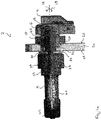
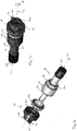
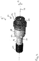
- Figure 1a illustrates a cross-sectional view, figure 1b an exploded perspective view and figure 1c a perspective view of a tyre parameter monitoring system 2 according to a first embodiment.
- the tyre parameter monitoring system 2 includes an electronic module 4 including a fitting 6, a valve stem 8 that is connectable with the electronic module 4 and a washer 10.
- the washer 10 includes interlocking means 12 with which the washer 10 is detachably attachable to the fitting 6 of the electronic module 4.
- the interlocking means 12 of the washer 10 is positioned within the fitting 6 of the electronic module 4 and is mechanically engaged with the fitting 6 so as to assemble the washer 10 and the electronic module 4.
- the interlocking means can also be disengaged to as to disassemble the washer 10 from the electronic module 4.
- the interlocking means 12 comprise two protrusions 14 which extend radially from the washer 10.
- the protrusions 14 may extends perpendicularly outwardly from a longitudinal axis 16 of the washer 10 and form wings or latches. However, the protrusions 14 may also extend at an inclined angle to the longitudinal axis 16.
- the two protrusions 14 are positioned uniformly around longitudinal axis 16 of the washer 10.
- the protrusions 14 are integral with an overmoulding 38 of the washer 10.
- the overmoulding 38 provides a protruding fitting 46 that is substantially cylindrical and that has an outer diameter which is smaller than the outer diameter of the washer body.
- the protrusions 14 each extend radially from the outer surface of the cylindrical protruding fitting 46 to form a wing or latch in the first embodiment.
- the number of protrusions 14 is not limited to two.
- one or more than two, for example three or four protrusions may be provided.
- the protrusion s14 may also extend radially outwardly at an inclines angle to the longitudinal axis 16.
- the fitting 6 of the electronic module 4 includes two indentations, which cannot be seen in the drawings, each corresponding to one of the protrusions 14 of washer 10 such that the protrusions 14 can be inserted into the indentations and interlocked with the indentations and the fitting 6 by means of a rotational movement around the axis 16 in the direction of the arrows 18 to assemble and disassemble the washer 10 and the electronic module 4.
- the tyre parameter monitoring system 2 further includes a seal 20 and a rubber seal 22. As is illustrated in the cross-sectional view of the tyre parameter monitoring system 2, when mounted on a wheel rim 24, the seal 20, the washer 10 and the electronic module 4 are positioned adjacent the inner surface 26 of the wheel rim 24 and, therefore, within the tyre which is attached the wheel rim 24.
- the seal 20 is positioned at least partially within an indentation 40 of the washer 10.
- the indentation 40 is positioned in the opposing face of the washer 10 from the protruding fitting 46.
- the seal 20 has a ring-shaped form with an inner diameter that is selected so as to be able to support the outer diameter of the valve stem 8.
- the rubber seal 22 and the valve stem 8 are positioned adjacent the outer surface 28 of the wheel rim 24 and outside of the tyre.
- the end face 36 of the valve stem 8 has a flat surface and the outer surface 24 of the wheel rim also has flat surface.
- the rubber seal 22 is clamped between the two flat surfaces 36, 28.
- the valve stem 8 includes a thread on its outer surface with which the valve stem 8 is connected to the fitting 6 of the electronic module 4.
- the valve stem 8 includes an outer surface 30 which is sized and shaped so as to provide an integral nut 32 with which the valve stem 8 can be tightened against the outer surface 28 of the wheel rim 24.
- the section of the outer surface 30 providing the integral nut 32 may have a hexagonal shape or one or more flat surfaces to assist gripping of the outer surface 30 and other sections of the valve stem 8 may have a different size and/or shape, for example be cylindrical.
- the valve stem 8 extends through the rubber seal 22, through a hole 34 in the wheel rim 24, through the seal 20 and washer 10 so as to be connected to the electronic module 4.
- the valve stem 8 also includes a cap 42 which covers a pin 44 positioned within the valve stem 8 to form the inflation valve.
- the pin 44 is movable along the longitudinal axis 16 of the valve stem 8 so as to open the valve in order to introduce air into, or remove air from, the tyre.
- FIG 2a illustrates an exploded view and figure 2b a perspective view of a tyre parameter monitoring system 2' according to a second embodiment.
- the tyre parameter monitoring system 2' of the second embodiment also includes an electronic module 4 comprising a fitting 6, a valve stem 8 which is connectable with electronic module 4 and a washer 10 including interlocking means 12 with which the washer 10 is detachably attachable to the fitting 6 of the electronic module 4.
- the interlocking means 12 of the washer 10 is provided by four protrusions 14 which extend radially from the washer 10 and which are uniformly distributed about the axis 16.
- the protrusions 14 have the form of ribs 48 which are positioned on and may be integrally formed from the outer surface of the cylindrical protruding fitting 46 of the washer 46.
- Each rib 48 has a long direction that is substantially parallel to the longitudinal axis 16, a height that extends substantially perpendicularly from the longitudinal axis 16 and a width that extends around the circumference of the cylindrical protruding fitting 46.
- the fitting 6 of the electronic module 4 includes four indentations not seen in figure 2 , one for each of the protrusions 14 so as to allow the washer 10 to be interlocked with the fitting 6 by a rotational movement of the washer 10 and protrusions 14 about the axis 16 as indicated by the arrow 18 in figure 2b .
- the washer 10 can be assembled to and disassembled from the electronic module 4 by means of this rotational action.
- Figure 3 illustrates a tyre pressure monitoring system 2" according to a third embodiment.
- the tyre parameter monitoring system 2" of the third embodiment differs in the form of the interlocking means 12 of the washer 10.
- the interlocking means 12 include at least one indentation 50 positioned in the outer surface of the washer 10.
- four indentations 50 are provided which are uniformly spaced about the axis 16 and which are positioned in an outer surface of the washer 10 so as to face radially outwards from the axis 16.
- the washer 10 includes a substantially cylindrical protruding fitting 46 and the indentations 40 are positioned in the outer surface of the substantially cylindrical protruding fitting 46.
- the fitting 6 of the electronic module 4 has a substantially cylindrical opening (not shown) and includes four protrusions that extend from the wall of the opening, each protrusion sized, shaped and positioned to correspond to one of the indentations 50 so as to provide a mechanical interlocking between the indentation 50 of the washer 10 and the protrusion of the fitting 6 of the electronic module 4 so as to allow the washer 10 to be detachably attached to the electronic module 4.
- the interlocking action may be a rotational action about the axis 16 as indicated by the arrow 18.
- an axial snapping action resulting interlocking between the indentations 50 and protrusions of the electronic module 4 may also be provided.
- Figure 4 illustrates a tyre parameter monitoring system 2"' according to a fourth embodiment.
- the tyre parameter monitoring system 2"' includes an adapter 52 which is attached to the fitting 6 of the electronic module 4.
- the adapter 52 protrudes from the fitting 6.
- the washer 10 includes an interlocking means 12 which is provided by the form of the outer surface of the washer 10 which interlocks with the fitting 6.
- the washer 10 includes a protruding fitting 46 that is substantially cylindrical and has at least one flat face that is engageable with a corresponding flat face of a substantially cylindrical opening of the fitting 6 of the electronic module 4.
- the washer 10 includes an indentation 40 in its end face that opposes the protruding fitting 46 that accommodates the seal 20.
- the adapter 52 protrudes through the washer 10, through the seal 20 and through the wheel rim.
- the adapter 52 is connected to the valve stem 8 by a threaded connection.
- the adapter 52 may include an external thread which engages with an internal thread of the valve stem 8.
- a seal such as an O-ring may be positioned between the adapter 52 and the valve stem 8.
- valve stem 8 is spaced apart from the electronic module 4 whereas in the embodiments illustrated in figures 1 to 3 , the valve stem extends into the electronic module 4.
- the outer surface 30 of the valve stem 8 of the tyre parameter monitoring system 2"' of the fourth embodiment may also include an integral nut 32 as in the embodiments illustrated in figures 1 to 3 .
- a tyre parameter monitoring system is provided that can be used with a clamp-in type valve and which enables the valve 8 to be assembled and disassembled from the electronic module 4 more easily, since the washer 10 is detachably attachable to the electronic module 4 by a purely mechanical interlocking action. Additionally, relative rotational movement between the washer 10 and the electronic module 4 can be restricted by appropriate design of the interlocking means 12 on the washer 10 and on the electronic module 4.
Landscapes
- Engineering & Computer Science (AREA)
- Mechanical Engineering (AREA)
- Measuring Fluid Pressure (AREA)
Abstract
Description
- The present invention relates to a system for measuring one or more parameters of a tyre fitted to a wheel rim of a vehicle, such as pressure of a tyre fitted to the wheel rim of a vehicle and to a method for mounting a tyre parameter monitoring system onto a wheel rim.
- Tyre parameter monitoring systems typically include an inflation valve for introducing or removing air from the tyre and an electronic module which includes a sensor unit or measuring one of more parameters of the tyre. The inflation valve is positioned in a bore or hole in the wheel rim and the electronic module is arranged inside the tyre and is coupled with the inflation valve. Such a system may be used to inform the driver of any abnormal variation in the measured parameter, for example the tyre pressure.
- One type of tyre parameter monitoring system or tyre pressure monitoring system (TPMS) is known as the snap-in type, in which the inflation valve positioned on the outside of the wheel rim extends through a bore in the wheel rim and is connected to an electronic unit positioned on the inside of the wheel rim by a snap-in connection. Snap-in valves include an elastically deformable stem. An example of such a snap-in system is disclosed in
EP 2 818 506 A1 - Another type of tyre parameter monitoring system is known as the clamp-in type. For the clamp-in type it is generally possible to fasten the electronic module in various angular positions with respect to the wheel rim. This enables the system to be mounted on wheel rims of different designs. An example of such a clamp-in system is disclosed in
US 7 059 178 B2 . - It is desirable to simplify assembly of the tyre parameter monitoring system to the wheel rim. An object of the present invention is, therefore, to provide a tyre pressure monitoring system that can be more easily mounted onto a wheel rim.
- According to the invention, a tyre parameter monitoring system is provided that comprises an electronic module with a fitting, a valve stem that is connectable with the electronic module and a washer. The washer comprises interlocking means with which the washer is detachably attachable to the fitting of the electronic module. The tyre parameter monitoring system may be a tyre pressure monitoring system.
- A tyre parameter monitoring system is, therefore, provided, in which the washer can be assembled with and disassembled from the electronic module when desired as the washer is detachably attachable by use of the interlocking means to the fitting of the electronic module. Therefore, the tyre parameter monitoring system can be more simply assembled and disassembled since the washer is mechanically detachably attached by use of the interlocking means to the fitting of the electronic module. The washer may be used in conjunction with a one or more seals which are used to provide an airtight connection between the valve stem and the electronic module.
- In some embodiments, the interlocking means is integral with an overmoulding of the washer. For example, the washer may include a mouldable material such as a plastic or metal which is shaped to form the interlocking means. In some embodiments, the interlocking means of the washer comprises at least one protrusion and the fitting of the electronic module comprises at least one indentation which corresponds to the protrusion of the washer so as to provide an interlocking mechanism between the washer and the fitting of the electronic module.
- Alternatively, the interlocking means of the washer may include at least one indentation and the fitting of the electronic module may include at least one protrusion corresponding to the indentation of the washer to provide an interlocking mechanism between the washer and the fitting of the electronic module.
- The washer may include a protruding fitting, which may for example be substantially cylindrical and have a diameter that is less than the diameter of the washer. The cylindrical protruding fitting is positioned in a substantially cylindrical opening of the fitting. The protrusions may extend radially from the protruding fitting and be engageable with an indentation in the wall of the opening of the fitting so as to interlock the protrusion with the indentation and detachable attach the washer to the fitting.
- In some embodiments, the interlocking action may be a rotational action about the longitudinal axis of the cylindrical protruding fitting and opening. The action may be a bayonet type action. The interlocking mechanism may provide a detachable connection that restricts relative rotational movement between the washer and the electronic module.
- In one embodiment, the interlocking means comprises two protrusions that extend radially from the washer, each protrusion interlocking with a corresponding indentation of the fitting to restrict rotational movement of the washer with respect to the electronic module. For example, the washer may include a cylindrical protruding fitting from which two protrusions may extend radially on opposing sides of the cylindrical protruding fitting. However, the number of protrusions as that extend radially from washer is not limited to two and one protrusion or more than two protrusions, for example three or four protrusions may be provided. The protrusions may be distributed uniformly around the circumference of the washer or protruding fitting, if provided.
- In some embodiments, the protrusions have the form of a latch or wing that extends radially outwardly from a longitudinal axis of the washer. The protrusions may extend substantially perpendicularly or at an inclined angle to the longitudinal axis.
- In some embodiments, the protrusions have the form of a rib having a long direction that extends parallel to the longitudinal axis, a height that extends radially from a longitudinal axis of the washer and a width that extends along the circumference of the protruding fitting.
- In some embodiments, the valve stem comprises an external thread which is engaged with an internal thread of the washer or an internal thread of the fitting of the electronic module in order to connect the valve stem to the washer and the electronic module.
- Typically, the valve stem is attached to the wheel rim using a nut which is placed over the outer surface of the valve stem and which is tightened against the outer surface of the wheel rim. In some embodiments, the valve stem comprises an outer surface that is sized and shaped so as to provide an integral nut. This embodiment has the advantage that the number of components of the system is reduced, thus further simplifying the assembly of the system onto the wheel rim.
- In some embodiments, the tyre parameter monitoring system further includes at least one seal. The seal may be clamped between the valve stem and the wheel rim in a mounted condition of the tyre parameter monitoring system. For example, the seal may be clamped between the valve stem and an outer surface of the wheel rim. In some embodiments, the seal is a rubber seal, for example an O-ring. In some embodiments, the rubber seal is clamped between a flat end surface of the valve stem and a flat surface of the wheel rim, for example a flat surface outer surface of the wheel rim in the mounted condition. This embodiment has the advantage that a groove for accommodating the seal is not required in the outer surface of the wheel rim or the end face of the valve stem. This arrangement further simplifies the construction of the tyre parameter monitoring system and assembly of the tyre parameter monitoring system to the wheel rim.
- In some embodiments, a seal is provided that is positioned on an inner surface of the wheel rim. The seal may be at least partially positioned within an indentation of the washer, the indentation being positioned at the opposing side of the washer from the interlocking means.
- In some embodiments, a seal is provided on each side of the wheel rim so that a first seal, for example a rubber O ring, is positioned between the valve stem and the outer surface of the wheel rim and a second seal is positioned between the washer and the inner surface of the wheel rim.
- In some embodiments, the valve stem extends into the electronic module, for example into the fitting of the electronic module and, therefore, extends through the wheel rim and the washer and any seals that are used. In embodiments in which the valve stem extends into the electronic module, the valve stem may be coupled with the electronic module by means of the washer.
- In some embodiments, the fitting of the electronic module comprises an adapter which protrudes outwardly from the electronic module through the washer and is connected with the valve stem. In these embodiments, the valve stem is spaced apart from the electronic module by the adapter and is coupled with the electronic module by means of the adapter, for example by means of a threaded connection between the valve stem and the adapter.
- The electronic module may include one or more sensor units or sense circuits for monitoring a parameter of the tyre that are positioned within a housing of the electronic module. In one particular embodiment, the electronic module accommodates a tyre pressure sensor unit.
- A method for mounting a tyre parameter monitoring system to a wheel rim is also provided. The method comprises positioning an electronic module which comprises a fitting on an inner surface of wheel rim, detachably attaching a washer comprising interlocking means with the fitting, the washer being positioned on the inner surface of the wheel rim, positioning a valve stem on the outer surface of the wheel rim and attaching the valve stem to the outer surface of the wheel by tightening the valve stem against the outer surface of the wheel rim using a nut.
- In some embodiments, the interlocking means of the washer comprises one or more protrusions which are connected to one or more corresponding indentations of the fitting to detachably attach the washer to the fitting of the electronic module. In an embodiment, the one or more protrusions extend radially from the washer and are engaged with a corresponding indentation of the fitting by a rotational movement of the washer around its axis to detachably attach the washer to the fitting of the electronic module by a mechanical interlocking action.
- In another embodiment, the interlocking means of the washer comprise one or more indentations which are connected to one or more corresponding protrusions of the fitting to detachably attach the washer to the fitting of the electronic module. The indentations may extend in a radial direction such that the washer can be detachably attached to the fitting of the electronic module by a rotational movement of the washer about the longitudinal axis of the washer so as to mechanically engage the indentations of the washer with the protrusion of the fitting.
- In some embodiments, one or more seals are provided. The method may include positioning a seal on the outer surface of the wheel rim such that the seal is positioned between the valve stem and the outer surface of the wheel rim and attaching the valve stem to the outer surface of the wheel rim by tightening the valve stem against the outer surface of the wheel rim using a nut and securing the seal between the valve stem and the outer surface.
- The method may also include positioning a seal on the inner surface of the wheel rim such that the seal is positioned between the washer and the inner surface of the wheel rim and attaching the washer to the inner surface of the wheel rim by tightening the valve stem against the outer surface of the wheel rim using a nut and securing the seal between the washer and the inner surface.
- In some embodiments, the valve stem includes an integral nut. The integral nut is provided by the outer surface of the nut that is sized and shaped to provide an integral nut.
- In an embodiment, the valve stem is inserted into a hole in the outer surface of the wheel rim and into the washer and into the fitting of the electronic module. The valve stem is tightened against the outer surface of the wheel rim using the integral nut to connect the valve stem with the electronic module.
- In other embodiments, the fitting of the electronic module comprises an adapter. The adapter is inserted through the washer and the hole in the wheel rim from the inner surface of the wheel rim. The adapter is connected to the valve stem by a threaded connection to connect the valve stem with the electronic module. The valve stem is tightened against the outer surface of the wheel rim using the integral nut. The valve stem is spaced apart from the electronic module by the adapter in this embodiment. In some embodiments, a seal such as an O-ring is positioned between the valve stem and the adapter.
- Embodiments will now be described with reference to the drawings.
-
Figure 1 a illustrates a cross-sectional view of a tyre parameter monitoring system according to a first embodiment mounted on a wheel rim. -
Figure 1b illustrates an exploded perspective view of the tyre parameter monitoring system offigures 1a and1b . -
Figure 1c illustrates a perspective view of the tyre parameter monitoring system offigure 1a . -
Figure 2a illustrates an exploded perspective view of a tyre parameter monitoring system according to a second embodiment. -
Figure 2b illustrates a perspective view of a tyre parameter monitoring system offigure 2a . -
Figure 3 illustrates a perspective view of a tyre parameter monitoring system according to a third embodiment. -
Figure 4 illustrates an exploded view of a tyre parameter monitoring system according to a fourth embodiment. -
Figure 1a illustrates a cross-sectional view,figure 1b an exploded perspective view andfigure 1c a perspective view of a tyreparameter monitoring system 2 according to a first embodiment. - The tyre
parameter monitoring system 2 includes anelectronic module 4 including afitting 6, avalve stem 8 that is connectable with theelectronic module 4 and awasher 10. Thewasher 10 includes interlocking means 12 with which thewasher 10 is detachably attachable to thefitting 6 of theelectronic module 4. The interlocking means 12 of thewasher 10 is positioned within thefitting 6 of theelectronic module 4 and is mechanically engaged with the fitting 6 so as to assemble thewasher 10 and theelectronic module 4. The interlocking means can also be disengaged to as to disassemble thewasher 10 from theelectronic module 4. - In the first embodiment, the interlocking means 12 comprise two
protrusions 14 which extend radially from thewasher 10. Theprotrusions 14 may extends perpendicularly outwardly from alongitudinal axis 16 of thewasher 10 and form wings or latches. However, theprotrusions 14 may also extend at an inclined angle to thelongitudinal axis 16. The twoprotrusions 14 are positioned uniformly aroundlongitudinal axis 16 of thewasher 10. In this embodiment, theprotrusions 14 are integral with anovermoulding 38 of thewasher 10. Theovermoulding 38 provides aprotruding fitting 46 that is substantially cylindrical and that has an outer diameter which is smaller than the outer diameter of the washer body. Theprotrusions 14 each extend radially from the outer surface of the cylindrical protruding fitting 46 to form a wing or latch in the first embodiment. However, the number ofprotrusions 14 is not limited to two. For example one or more than two, for example three or four protrusions may be provided. The protrusion s14 may also extend radially outwardly at an inclines angle to thelongitudinal axis 16. - The
fitting 6 of theelectronic module 4 includes two indentations, which cannot be seen in the drawings, each corresponding to one of theprotrusions 14 ofwasher 10 such that theprotrusions 14 can be inserted into the indentations and interlocked with the indentations and thefitting 6 by means of a rotational movement around theaxis 16 in the direction of thearrows 18 to assemble and disassemble thewasher 10 and theelectronic module 4. - The tyre
parameter monitoring system 2 further includes aseal 20 and arubber seal 22. As is illustrated in the cross-sectional view of the tyreparameter monitoring system 2, when mounted on awheel rim 24, theseal 20, thewasher 10 and theelectronic module 4 are positioned adjacent the inner surface 26 of thewheel rim 24 and, therefore, within the tyre which is attached thewheel rim 24. Theseal 20 is positioned at least partially within anindentation 40 of thewasher 10. Theindentation 40 is positioned in the opposing face of thewasher 10 from the protrudingfitting 46. Theseal 20 has a ring-shaped form with an inner diameter that is selected so as to be able to support the outer diameter of thevalve stem 8. - The
rubber seal 22 and thevalve stem 8 are positioned adjacent theouter surface 28 of thewheel rim 24 and outside of the tyre. In this embodiment, theend face 36 of thevalve stem 8 has a flat surface and theouter surface 24 of the wheel rim also has flat surface. Therubber seal 22 is clamped between the twoflat surfaces valve stem 8 includes a thread on its outer surface with which thevalve stem 8 is connected to thefitting 6 of theelectronic module 4. - In the embodiment illustrated with reference to
figure 1 , thevalve stem 8 includes anouter surface 30 which is sized and shaped so as to provide anintegral nut 32 with which thevalve stem 8 can be tightened against theouter surface 28 of thewheel rim 24. The section of theouter surface 30 providing theintegral nut 32 may have a hexagonal shape or one or more flat surfaces to assist gripping of theouter surface 30 and other sections of thevalve stem 8 may have a different size and/or shape, for example be cylindrical. In the assembled condition illustrated infigure 1a , thevalve stem 8 extends through therubber seal 22, through ahole 34 in thewheel rim 24, through theseal 20 andwasher 10 so as to be connected to theelectronic module 4. - The valve stem 8 also includes a
cap 42 which covers a pin 44 positioned within thevalve stem 8 to form the inflation valve. The pin 44 is movable along thelongitudinal axis 16 of thevalve stem 8 so as to open the valve in order to introduce air into, or remove air from, the tyre. -
Figure 2a illustrates an exploded view andfigure 2b a perspective view of a tyre parameter monitoring system 2' according to a second embodiment. The tyre parameter monitoring system 2' of the second embodiment also includes anelectronic module 4 comprising afitting 6, avalve stem 8 which is connectable withelectronic module 4 and awasher 10 including interlocking means 12 with which thewasher 10 is detachably attachable to thefitting 6 of theelectronic module 4. In the second embodiment, the interlocking means 12 of thewasher 10 is provided by fourprotrusions 14 which extend radially from thewasher 10 and which are uniformly distributed about theaxis 16. - In this embodiment, the
protrusions 14 have the form ofribs 48 which are positioned on and may be integrally formed from the outer surface of the cylindrical protruding fitting 46 of thewasher 46. Eachrib 48 has a long direction that is substantially parallel to thelongitudinal axis 16, a height that extends substantially perpendicularly from thelongitudinal axis 16 and a width that extends around the circumference of the cylindrical protruding fitting 46. - The
fitting 6 of theelectronic module 4 includes four indentations not seen infigure 2 , one for each of theprotrusions 14 so as to allow thewasher 10 to be interlocked with thefitting 6 by a rotational movement of thewasher 10 andprotrusions 14 about theaxis 16 as indicated by thearrow 18 infigure 2b . Thewasher 10 can be assembled to and disassembled from theelectronic module 4 by means of this rotational action. -
Figure 3 illustrates a tyrepressure monitoring system 2" according to a third embodiment. The tyreparameter monitoring system 2" of the third embodiment differs in the form of the interlocking means 12 of thewasher 10. In the embodiment illustrated infigure 3 , the interlocking means 12 include at least one indentation 50 positioned in the outer surface of thewasher 10. In this particular embodiment, four indentations 50 are provided which are uniformly spaced about theaxis 16 and which are positioned in an outer surface of thewasher 10 so as to face radially outwards from theaxis 16. In this embodiment, thewasher 10 includes a substantially cylindrical protruding fitting 46 and theindentations 40 are positioned in the outer surface of the substantially cylindrical protruding fitting 46. - The
fitting 6 of theelectronic module 4 has a substantially cylindrical opening (not shown) and includes four protrusions that extend from the wall of the opening, each protrusion sized, shaped and positioned to correspond to one of the indentations 50 so as to provide a mechanical interlocking between the indentation 50 of thewasher 10 and the protrusion of thefitting 6 of theelectronic module 4 so as to allow thewasher 10 to be detachably attached to theelectronic module 4. - In some embodiments, the interlocking action may be a rotational action about the
axis 16 as indicated by thearrow 18. However, in a non-illustrated embodiment, an axial snapping action resulting interlocking between the indentations 50 and protrusions of theelectronic module 4 may also be provided. -
Figure 4 illustrates a tyreparameter monitoring system 2"' according to a fourth embodiment. In this embodiment, the tyreparameter monitoring system 2"' includes anadapter 52 which is attached to thefitting 6 of theelectronic module 4. Theadapter 52 protrudes from thefitting 6. In this embodiment, thewasher 10 includes an interlocking means 12 which is provided by the form of the outer surface of thewasher 10 which interlocks with thefitting 6. In this embodiment, thewasher 10 includes a protruding fitting 46 that is substantially cylindrical and has at least one flat face that is engageable with a corresponding flat face of a substantially cylindrical opening of thefitting 6 of theelectronic module 4. Thewasher 10 includes anindentation 40 in its end face that opposes the protruding fitting 46 that accommodates theseal 20. - In this embodiment, the
adapter 52 protrudes through thewasher 10, through theseal 20 and through the wheel rim. Theadapter 52 is connected to thevalve stem 8 by a threaded connection. Theadapter 52 may include an external thread which engages with an internal thread of thevalve stem 8. A seal such as an O-ring may be positioned between theadapter 52 and thevalve stem 8. - In this embodiment, the
valve stem 8 is spaced apart from theelectronic module 4 whereas in the embodiments illustrated infigures 1 to 3 , the valve stem extends into theelectronic module 4. Theouter surface 30 of thevalve stem 8 of the tyreparameter monitoring system 2"' of the fourth embodiment may also include anintegral nut 32 as in the embodiments illustrated infigures 1 to 3 . - A tyre parameter monitoring system is provided that can be used with a clamp-in type valve and which enables the
valve 8 to be assembled and disassembled from theelectronic module 4 more easily, since thewasher 10 is detachably attachable to theelectronic module 4 by a purely mechanical interlocking action. Additionally, relative rotational movement between thewasher 10 and theelectronic module 4 can be restricted by appropriate design of the interlocking means 12 on thewasher 10 and on theelectronic module 4.
Claims (15)
- A tyre parameter monitoring system (2), comprising:an electronic module (4) comprising a fitting (6);a valve stem (8) that is connectable with the electronic module (4);a washer (10),wherein the washer (10) comprises interlocking means (12) with which the washer (10) is detachably attachable to the fitting (6) of the electronic module (4).
- A tyre parameter monitoring system (2) according to claim 1, wherein the interlocking means (12) is integral with an overmoulding (38) of the washer (10).
- A tyre parameter monitoring system (2) according to one of claims 1 or 2, wherein the interlocking means (12) comprises at least one protrusion (14) and the fitting (6) comprises at least one indentation or the interlocking means comprises at least one indentation (50) and the fitting (6) comprises at least one protrusion.
- A tyre parameter monitoring system (2) according to one of claims 1 to 3, wherein the interlocking means (12) comprises two protrusions (14) that extend radially from the washer (10), each protrusion (14) interlocking with an indentation of the fitting (6) to restrict rotational movement of the washer (10) with respect to the electronic module (4).
- A tyre parameter monitoring system (2) according to one of claims 1 to 4, wherein the valve stem (8) comprises an external thread that couples with an internal thread of the washer (10) to connect the valve stem (8) to the electronic module (4).
- A tyre parameter monitoring system (2) according to one of claims 1 to 5, wherein the valve stem (8) comprises an outer surface (30) that is sized and shaped to provide an integral nut (32).
- A tyre parameter monitoring system (2) according to one of claims 1 to 6, further comprising a seal (20, 22), wherein the seal (20, 22) is clamped between the valve stem (8) and a wheel rim (24) in a mounted condition of the tyre parameter monitoring system (2).
- A tyre parameter monitoring system (2) according to claim 7, wherein the seal is a rubber seal (22) and the rubber seal (22) is clamped between a flat surface (36) of the valve stem (8) and a flat surface (28) of the wheel rim (24) in the mounted condition.
- A tyre parameter monitoring system (2) according to one of claims 1 to 8, wherein the valve stem (8) extends into the electronic module (4).
- A tyre parameter monitoring system (2) according to one of claims 1 to 8, wherein the fitting (6) comprises an adapter (52) which protrudes through the washer (10) and is connected with the valve stem (8).
- A tyre parameter monitoring system (2) according claim 10, wherein the valve stem (8) is spaced apart from the electronic module (4) and is coupled with the electronic module (4) by means of the adapter (52) and the washer (10).
- A tyre parameter monitoring system (2) according to one of claims 1 to 11, wherein the electronic module (4) accommodates a tyre pressure sensor unit.
- A method for mounting a tyre parameter monitoring system (2) to a wheel rim of a vehicle, the method comprising:positioning an electronic module (4) with a fitting (6) on an inner surface (26) of the wheel rim (24);detachably attaching a washer (10) comprising interlocking means (12) with the fitting (6), the washer (10) being positioned on the inner surface (26) of the wheel rim (24);
positioning a valve stem (8) on an outer surface (26) of the wheel rim (24);attaching the valve stem (8) to the outer surface (28) of the wheel rim (24) by tightening the valve stem (8) against the outer surface (28) of the wheel rim (24) using a nut (24). - A method according to claim 13, wherein
the interlocking means (12) comprises one or more protrusions (14) that are connected to one or more corresponding indentations of the fitting (6) to detachably attach the washer (10) to the fitting (6) of the electronic module (4) or to detach the washer (10) from the fitting of the electronic module (4), or
the interlocking means (12) comprise one or more indentations (50) that are connected to one or more corresponding protrusions of the fitting (6) to detachably attach the washer (10) to the fitting (6) of the electronic module (4) or to detach the washer (10) from the fitting of the electronic module (4). - A method according to claim 13 to claim 14, wherein the valve stem (8) comprises an outer surface (30) that is sized and shaped to provide an integral nut (32), wherein the method further comprises:inserting the valve stem (8) into a hole (34) of the wheel rim (24) and into the washer (10), and tightening the valve stem (8) against the outer surface (28) of the wheel rim (24) using the integral nut (32) to connect the valve stem (8) with the electronic module (4), orthe fitting (6) of the electronic module (4) comprises an adapter (52) and the adapter (52) is inserted through the washer (10) and the hole (34) in the wheel rim (24) and the adapter (52) is connected to the valve stem (8) by a thread to connect the valve stem (8) with the electronic module (4), and the valve stem (8) is tightened against the outer surface (28) of the wheel rim (24) using the integral nut (32).
Priority Applications (1)
| Application Number | Priority Date | Filing Date | Title |
|---|---|---|---|
| EP20465503.9A EP3858645B1 (en) | 2020-01-29 | 2020-01-29 | Tyre parameter monitoring system and method for mounting a tyre parameter monitoring system onto a wheel rim of a vehicle |
Applications Claiming Priority (1)
| Application Number | Priority Date | Filing Date | Title |
|---|---|---|---|
| EP20465503.9A EP3858645B1 (en) | 2020-01-29 | 2020-01-29 | Tyre parameter monitoring system and method for mounting a tyre parameter monitoring system onto a wheel rim of a vehicle |
Publications (2)
| Publication Number | Publication Date |
|---|---|
| EP3858645A1 true EP3858645A1 (en) | 2021-08-04 |
| EP3858645B1 EP3858645B1 (en) | 2024-10-16 |
Family
ID=69467492
Family Applications (1)
| Application Number | Title | Priority Date | Filing Date |
|---|---|---|---|
| EP20465503.9A Active EP3858645B1 (en) | 2020-01-29 | 2020-01-29 | Tyre parameter monitoring system and method for mounting a tyre parameter monitoring system onto a wheel rim of a vehicle |
Country Status (1)
| Country | Link |
|---|---|
| EP (1) | EP3858645B1 (en) |
Cited By (1)
| Publication number | Priority date | Publication date | Assignee | Title |
|---|---|---|---|---|
| US20210252922A1 (en) * | 2020-02-14 | 2021-08-19 | Continental Automotive Gmbh | Valve system, tire parameter monitoring system and method for mounting a tire parameter monitoring system onto a wheel rim of a vehicle |
Citations (6)
| Publication number | Priority date | Publication date | Assignee | Title |
|---|---|---|---|---|
| US7059178B2 (en) | 2001-10-04 | 2006-06-13 | Siemens Aktiengesellschaft | Device for measuring a tire pressure |
| US20080276995A1 (en) * | 2007-05-09 | 2008-11-13 | Lv Sensors, Inc. | Monitoring device attachment to rubber valve stems |
| US20110000293A1 (en) * | 2006-10-23 | 2011-01-06 | Dominique Luce | Device for mechanically fastening a tyre sensor to a rim |
| DE202014103121U1 (en) * | 2014-07-07 | 2014-07-18 | E-Lead Electronic Co., Ltd. | Flexible tire valve with a reinforced inner frame |
| EP2818506A1 (en) | 2013-06-27 | 2014-12-31 | Continental Automotive GmbH | Valve body for a snap in valve and snap in valve |
| CN205086612U (en) * | 2015-10-12 | 2016-03-16 | 铁将军汽车电子有限公司 | tire pressure gauge |
-
2020
- 2020-01-29 EP EP20465503.9A patent/EP3858645B1/en active Active
Patent Citations (6)
| Publication number | Priority date | Publication date | Assignee | Title |
|---|---|---|---|---|
| US7059178B2 (en) | 2001-10-04 | 2006-06-13 | Siemens Aktiengesellschaft | Device for measuring a tire pressure |
| US20110000293A1 (en) * | 2006-10-23 | 2011-01-06 | Dominique Luce | Device for mechanically fastening a tyre sensor to a rim |
| US20080276995A1 (en) * | 2007-05-09 | 2008-11-13 | Lv Sensors, Inc. | Monitoring device attachment to rubber valve stems |
| EP2818506A1 (en) | 2013-06-27 | 2014-12-31 | Continental Automotive GmbH | Valve body for a snap in valve and snap in valve |
| DE202014103121U1 (en) * | 2014-07-07 | 2014-07-18 | E-Lead Electronic Co., Ltd. | Flexible tire valve with a reinforced inner frame |
| CN205086612U (en) * | 2015-10-12 | 2016-03-16 | 铁将军汽车电子有限公司 | tire pressure gauge |
Cited By (2)
| Publication number | Priority date | Publication date | Assignee | Title |
|---|---|---|---|---|
| US20210252922A1 (en) * | 2020-02-14 | 2021-08-19 | Continental Automotive Gmbh | Valve system, tire parameter monitoring system and method for mounting a tire parameter monitoring system onto a wheel rim of a vehicle |
| US11724553B2 (en) * | 2020-02-14 | 2023-08-15 | Continental Automotive Gmbh | Valve system, tire parameter monitoring system and method for mounting a tire parameter monitoring system onto a wheel rim of a vehicle |
Also Published As
| Publication number | Publication date |
|---|---|
| EP3858645B1 (en) | 2024-10-16 |
Similar Documents
| Publication | Publication Date | Title |
|---|---|---|
| CN101687448B (en) | Electronic unit for measuring wheel operating parameters including electronic module and inflation valve of the "snap-in" type | |
| KR101137813B1 (en) | Tire Pressure Monitoring System and Tire Pressure Sensor thereof | |
| US10549586B1 (en) | Electronic unit for measuring operating parameters of a vehicle wheel | |
| US8146413B1 (en) | Two-port tire valve stem | |
| EP1661736A2 (en) | Valve device | |
| US11724553B2 (en) | Valve system, tire parameter monitoring system and method for mounting a tire parameter monitoring system onto a wheel rim of a vehicle | |
| EP1911610A1 (en) | Tire valve unit | |
| CN102686419A (en) | Electronic unit including electronic module and inflation valve for measuring wheel operating parameters | |
| US11970029B2 (en) | Adapter, tyre parameter monitoring system and method for mounting a tyre parameter monitoring system onto a wheel rim | |
| US20100319447A1 (en) | Cutting insert | |
| EP1452347B1 (en) | Casing structure of transmitter for use in tire condition monitoring apparatus | |
| CN101466561A (en) | Tyre valve and process for removing it | |
| JP2009543726A (en) | Spoke fixing device for spoke wheel to rim | |
| US9884526B2 (en) | Electronic unit for measuring working parameters of a vehicle wheel | |
| CN108025608B (en) | Tire condition monitoring device | |
| EP3858645B1 (en) | Tyre parameter monitoring system and method for mounting a tyre parameter monitoring system onto a wheel rim of a vehicle | |
| EP4311696B1 (en) | Tire inflation valve and related valve-sensor assembly | |
| EP3366498B1 (en) | Tire-state detection device | |
| EP3450222B1 (en) | Tire condition detecting apparatus, clamp-in valve and tire valve unit | |
| US10940723B2 (en) | Electronic unit for measuring operating parameters of a vehicle wheel, comprising an electronic casing and an inflation valve of elastically deformable type | |
| GB2594991A (en) | Valve stem, tyre parameter monitoring system and method for mounting a tyre parameter monitoring system onto a wheel rim or a vehicle | |
| GB2580387A (en) | Adapter, tyre parameter monitoring system and method for mounting a tyre parameter monitoring system onto a wheel rim | |
| US20080184786A1 (en) | Wheel sensor with valve | |
| EP2331828B1 (en) | Device for providing air under pressure and automotive vehicle equipped with such a device |
Legal Events
| Date | Code | Title | Description |
|---|---|---|---|
| PUAI | Public reference made under article 153(3) epc to a published international application that has entered the european phase |
Free format text: ORIGINAL CODE: 0009012 |
|
| STAA | Information on the status of an ep patent application or granted ep patent |
Free format text: STATUS: THE APPLICATION HAS BEEN PUBLISHED |
|
| AK | Designated contracting states |
Kind code of ref document: A1 Designated state(s): AL AT BE BG CH CY CZ DE DK EE ES FI FR GB GR HR HU IE IS IT LI LT LU LV MC MK MT NL NO PL PT RO RS SE SI SK SM TR |
|
| STAA | Information on the status of an ep patent application or granted ep patent |
Free format text: STATUS: REQUEST FOR EXAMINATION WAS MADE |
|
| 17P | Request for examination filed |
Effective date: 20220204 |
|
| RBV | Designated contracting states (corrected) |
Designated state(s): AL AT BE BG CH CY CZ DE DK EE ES FI FR GB GR HR HU IE IS IT LI LT LU LV MC MK MT NL NO PL PT RO RS SE SI SK SM TR |
|
| RAP1 | Party data changed (applicant data changed or rights of an application transferred) |
Owner name: CONTINENTAL AUTOMOTIVE TECHNOLOGIES GMBH |
|
| STAA | Information on the status of an ep patent application or granted ep patent |
Free format text: STATUS: EXAMINATION IS IN PROGRESS |
|
| 17Q | First examination report despatched |
Effective date: 20230404 |
|
| RAP3 | Party data changed (applicant data changed or rights of an application transferred) |
Owner name: CONTINENTAL AUTOMOTIVE TECHNOLOGIES GMBH |
|
| GRAP | Despatch of communication of intention to grant a patent |
Free format text: ORIGINAL CODE: EPIDOSNIGR1 |
|
| STAA | Information on the status of an ep patent application or granted ep patent |
Free format text: STATUS: GRANT OF PATENT IS INTENDED |
|
| INTG | Intention to grant announced |
Effective date: 20240527 |
|
| GRAS | Grant fee paid |
Free format text: ORIGINAL CODE: EPIDOSNIGR3 |
|
| GRAA | (expected) grant |
Free format text: ORIGINAL CODE: 0009210 |
|
| STAA | Information on the status of an ep patent application or granted ep patent |
Free format text: STATUS: THE PATENT HAS BEEN GRANTED |
|
| AK | Designated contracting states |
Kind code of ref document: B1 Designated state(s): AL AT BE BG CH CY CZ DE DK EE ES FI FR GB GR HR HU IE IS IT LI LT LU LV MC MK MT NL NO PL PT RO RS SE SI SK SM TR |
|
| REG | Reference to a national code |
Ref country code: GB Ref legal event code: FG4D |
|
| REG | Reference to a national code |
Ref country code: CH Ref legal event code: EP Ref country code: DE Ref legal event code: R096 Ref document number: 602020039498 Country of ref document: DE |
|
| REG | Reference to a national code |
Ref country code: IE Ref legal event code: FG4D |
|
| REG | Reference to a national code |
Ref country code: LT Ref legal event code: MG9D |
|
| REG | Reference to a national code |
Ref country code: NL Ref legal event code: MP Effective date: 20241016 |
|
| REG | Reference to a national code |
Ref country code: AT Ref legal event code: MK05 Ref document number: 1732661 Country of ref document: AT Kind code of ref document: T Effective date: 20241016 |
|
| PG25 | Lapsed in a contracting state [announced via postgrant information from national office to epo] |
Ref country code: NL Free format text: LAPSE BECAUSE OF FAILURE TO SUBMIT A TRANSLATION OF THE DESCRIPTION OR TO PAY THE FEE WITHIN THE PRESCRIBED TIME-LIMIT Effective date: 20241016 |
|
| PG25 | Lapsed in a contracting state [announced via postgrant information from national office to epo] |
Ref country code: NL Free format text: LAPSE BECAUSE OF FAILURE TO SUBMIT A TRANSLATION OF THE DESCRIPTION OR TO PAY THE FEE WITHIN THE PRESCRIBED TIME-LIMIT Effective date: 20241016 |
|
| PG25 | Lapsed in a contracting state [announced via postgrant information from national office to epo] |
Ref country code: HR Free format text: LAPSE BECAUSE OF FAILURE TO SUBMIT A TRANSLATION OF THE DESCRIPTION OR TO PAY THE FEE WITHIN THE PRESCRIBED TIME-LIMIT Effective date: 20241016 Ref country code: IS Free format text: LAPSE BECAUSE OF FAILURE TO SUBMIT A TRANSLATION OF THE DESCRIPTION OR TO PAY THE FEE WITHIN THE PRESCRIBED TIME-LIMIT Effective date: 20250216 Ref country code: PT Free format text: LAPSE BECAUSE OF FAILURE TO SUBMIT A TRANSLATION OF THE DESCRIPTION OR TO PAY THE FEE WITHIN THE PRESCRIBED TIME-LIMIT Effective date: 20250217 |
|
| PG25 | Lapsed in a contracting state [announced via postgrant information from national office to epo] |
Ref country code: FI Free format text: LAPSE BECAUSE OF FAILURE TO SUBMIT A TRANSLATION OF THE DESCRIPTION OR TO PAY THE FEE WITHIN THE PRESCRIBED TIME-LIMIT Effective date: 20241016 |
|
| PG25 | Lapsed in a contracting state [announced via postgrant information from national office to epo] |
Ref country code: BG Free format text: LAPSE BECAUSE OF FAILURE TO SUBMIT A TRANSLATION OF THE DESCRIPTION OR TO PAY THE FEE WITHIN THE PRESCRIBED TIME-LIMIT Effective date: 20241016 |
|
| PG25 | Lapsed in a contracting state [announced via postgrant information from national office to epo] |
Ref country code: ES Free format text: LAPSE BECAUSE OF FAILURE TO SUBMIT A TRANSLATION OF THE DESCRIPTION OR TO PAY THE FEE WITHIN THE PRESCRIBED TIME-LIMIT Effective date: 20241016 |
|
| PG25 | Lapsed in a contracting state [announced via postgrant information from national office to epo] |
Ref country code: NO Free format text: LAPSE BECAUSE OF FAILURE TO SUBMIT A TRANSLATION OF THE DESCRIPTION OR TO PAY THE FEE WITHIN THE PRESCRIBED TIME-LIMIT Effective date: 20250116 |
|
| PG25 | Lapsed in a contracting state [announced via postgrant information from national office to epo] |
Ref country code: AT Free format text: LAPSE BECAUSE OF FAILURE TO SUBMIT A TRANSLATION OF THE DESCRIPTION OR TO PAY THE FEE WITHIN THE PRESCRIBED TIME-LIMIT Effective date: 20241016 Ref country code: LV Free format text: LAPSE BECAUSE OF FAILURE TO SUBMIT A TRANSLATION OF THE DESCRIPTION OR TO PAY THE FEE WITHIN THE PRESCRIBED TIME-LIMIT Effective date: 20241016 Ref country code: GR Free format text: LAPSE BECAUSE OF FAILURE TO SUBMIT A TRANSLATION OF THE DESCRIPTION OR TO PAY THE FEE WITHIN THE PRESCRIBED TIME-LIMIT Effective date: 20250117 |
|
| PG25 | Lapsed in a contracting state [announced via postgrant information from national office to epo] |
Ref country code: PL Free format text: LAPSE BECAUSE OF FAILURE TO SUBMIT A TRANSLATION OF THE DESCRIPTION OR TO PAY THE FEE WITHIN THE PRESCRIBED TIME-LIMIT Effective date: 20241016 |
|
| PG25 | Lapsed in a contracting state [announced via postgrant information from national office to epo] |
Ref country code: RS Free format text: LAPSE BECAUSE OF FAILURE TO SUBMIT A TRANSLATION OF THE DESCRIPTION OR TO PAY THE FEE WITHIN THE PRESCRIBED TIME-LIMIT Effective date: 20250116 |
|
| PG25 | Lapsed in a contracting state [announced via postgrant information from national office to epo] |
Ref country code: SM Free format text: LAPSE BECAUSE OF FAILURE TO SUBMIT A TRANSLATION OF THE DESCRIPTION OR TO PAY THE FEE WITHIN THE PRESCRIBED TIME-LIMIT Effective date: 20241016 |
|
| PG25 | Lapsed in a contracting state [announced via postgrant information from national office to epo] |
Ref country code: DK Free format text: LAPSE BECAUSE OF FAILURE TO SUBMIT A TRANSLATION OF THE DESCRIPTION OR TO PAY THE FEE WITHIN THE PRESCRIBED TIME-LIMIT Effective date: 20241016 |
|
| REG | Reference to a national code |
Ref country code: DE Ref legal event code: R097 Ref document number: 602020039498 Country of ref document: DE |
|
| PG25 | Lapsed in a contracting state [announced via postgrant information from national office to epo] |
Ref country code: EE Free format text: LAPSE BECAUSE OF FAILURE TO SUBMIT A TRANSLATION OF THE DESCRIPTION OR TO PAY THE FEE WITHIN THE PRESCRIBED TIME-LIMIT Effective date: 20241016 |
|
| PG25 | Lapsed in a contracting state [announced via postgrant information from national office to epo] |
Ref country code: RO Free format text: LAPSE BECAUSE OF FAILURE TO SUBMIT A TRANSLATION OF THE DESCRIPTION OR TO PAY THE FEE WITHIN THE PRESCRIBED TIME-LIMIT Effective date: 20241016 |
|
| PG25 | Lapsed in a contracting state [announced via postgrant information from national office to epo] |
Ref country code: SK Free format text: LAPSE BECAUSE OF FAILURE TO SUBMIT A TRANSLATION OF THE DESCRIPTION OR TO PAY THE FEE WITHIN THE PRESCRIBED TIME-LIMIT Effective date: 20241016 |
|
| PG25 | Lapsed in a contracting state [announced via postgrant information from national office to epo] |
Ref country code: CZ Free format text: LAPSE BECAUSE OF FAILURE TO SUBMIT A TRANSLATION OF THE DESCRIPTION OR TO PAY THE FEE WITHIN THE PRESCRIBED TIME-LIMIT Effective date: 20241016 |
|
| PG25 | Lapsed in a contracting state [announced via postgrant information from national office to epo] |
Ref country code: IT Free format text: LAPSE BECAUSE OF FAILURE TO SUBMIT A TRANSLATION OF THE DESCRIPTION OR TO PAY THE FEE WITHIN THE PRESCRIBED TIME-LIMIT Effective date: 20241016 |
|
| PLBE | No opposition filed within time limit |
Free format text: ORIGINAL CODE: 0009261 |
|
| STAA | Information on the status of an ep patent application or granted ep patent |
Free format text: STATUS: NO OPPOSITION FILED WITHIN TIME LIMIT |
|
| REG | Reference to a national code |
Ref country code: CH Ref legal event code: PL |
|
| PG25 | Lapsed in a contracting state [announced via postgrant information from national office to epo] |
Ref country code: SE Free format text: LAPSE BECAUSE OF FAILURE TO SUBMIT A TRANSLATION OF THE DESCRIPTION OR TO PAY THE FEE WITHIN THE PRESCRIBED TIME-LIMIT Effective date: 20241016 |
|
| PG25 | Lapsed in a contracting state [announced via postgrant information from national office to epo] |
Ref country code: MC Free format text: LAPSE BECAUSE OF FAILURE TO SUBMIT A TRANSLATION OF THE DESCRIPTION OR TO PAY THE FEE WITHIN THE PRESCRIBED TIME-LIMIT Effective date: 20241016 Ref country code: LU Free format text: LAPSE BECAUSE OF NON-PAYMENT OF DUE FEES Effective date: 20250129 |
|
| 26N | No opposition filed |
Effective date: 20250717 |
|
| GBPC | Gb: european patent ceased through non-payment of renewal fee |
Effective date: 20250129 |
|
| PG25 | Lapsed in a contracting state [announced via postgrant information from national office to epo] |
Ref country code: GB Free format text: LAPSE BECAUSE OF NON-PAYMENT OF DUE FEES Effective date: 20250129 Ref country code: BE Free format text: LAPSE BECAUSE OF NON-PAYMENT OF DUE FEES Effective date: 20250131 |
|
| PG25 | Lapsed in a contracting state [announced via postgrant information from national office to epo] |
Ref country code: FR Free format text: LAPSE BECAUSE OF NON-PAYMENT OF DUE FEES Effective date: 20250131 |
|
| PG25 | Lapsed in a contracting state [announced via postgrant information from national office to epo] |
Ref country code: CH Free format text: LAPSE BECAUSE OF NON-PAYMENT OF DUE FEES Effective date: 20250131 |
|
| REG | Reference to a national code |
Ref country code: BE Ref legal event code: MM Effective date: 20250131 |
|
| PG25 | Lapsed in a contracting state [announced via postgrant information from national office to epo] |
Ref country code: IE Free format text: LAPSE BECAUSE OF NON-PAYMENT OF DUE FEES Effective date: 20250129 |
|
| REG | Reference to a national code |
Ref country code: DE Ref legal event code: R081 Ref document number: 602020039498 Country of ref document: DE Owner name: AUMOVIO GERMANY GMBH, DE Free format text: FORMER OWNER: CONTINENTAL AUTOMOTIVE TECHNOLOGIES GMBH, 30175 HANNOVER, DE |
|
| PGFP | Annual fee paid to national office [announced via postgrant information from national office to epo] |
Ref country code: DE Payment date: 20260131 Year of fee payment: 7 |
|
| PG25 | Lapsed in a contracting state [announced via postgrant information from national office to epo] |
Ref country code: CY Free format text: LAPSE BECAUSE OF FAILURE TO SUBMIT A TRANSLATION OF THE DESCRIPTION OR TO PAY THE FEE WITHIN THE PRESCRIBED TIME-LIMIT Effective date: 20241016 |
|
| PG25 | Lapsed in a contracting state [announced via postgrant information from national office to epo] |
Ref country code: TR Free format text: LAPSE BECAUSE OF FAILURE TO SUBMIT A TRANSLATION OF THE DESCRIPTION OR TO PAY THE FEE WITHIN THE PRESCRIBED TIME-LIMIT Effective date: 20241016 |
|
| PG25 | Lapsed in a contracting state [announced via postgrant information from national office to epo] |
Ref country code: LT Free format text: LAPSE BECAUSE OF FAILURE TO SUBMIT A TRANSLATION OF THE DESCRIPTION OR TO PAY THE FEE WITHIN THE PRESCRIBED TIME-LIMIT Effective date: 20241016 |