EP3858562A1 - Cutting tool - Google Patents
Cutting tool Download PDFInfo
- Publication number
- EP3858562A1 EP3858562A1 EP20154316.2A EP20154316A EP3858562A1 EP 3858562 A1 EP3858562 A1 EP 3858562A1 EP 20154316 A EP20154316 A EP 20154316A EP 3858562 A1 EP3858562 A1 EP 3858562A1
- Authority
- EP
- European Patent Office
- Prior art keywords
- handle
- blade
- cutting tool
- form fit
- cutting
- Prior art date
- Legal status (The legal status is an assumption and is not a legal conclusion. Google has not performed a legal analysis and makes no representation as to the accuracy of the status listed.)
- Withdrawn
Links
Images


Classifications
-
- B—PERFORMING OPERATIONS; TRANSPORTING
- B26—HAND CUTTING TOOLS; CUTTING; SEVERING
- B26B—HAND-HELD CUTTING TOOLS NOT OTHERWISE PROVIDED FOR
- B26B13/00—Hand shears; Scissors
- B26B13/28—Joints
- B26B13/285—Joints with means for applying pressure on the blades; with means for producing "drawing-cut" effect
-
- A—HUMAN NECESSITIES
- A01—AGRICULTURE; FORESTRY; ANIMAL HUSBANDRY; HUNTING; TRAPPING; FISHING
- A01G—HORTICULTURE; CULTIVATION OF VEGETABLES, FLOWERS, RICE, FRUIT, VINES, HOPS OR SEAWEED; FORESTRY; WATERING
- A01G3/00—Cutting implements specially adapted for horticultural purposes; Delimbing standing trees
- A01G3/02—Secateurs; Flower or fruit shears
- A01G3/033—Secateurs; Flower or fruit shears having motor-driven blades
- A01G3/037—Secateurs; Flower or fruit shears having motor-driven blades the driving means being an electric motor
-
- B—PERFORMING OPERATIONS; TRANSPORTING
- B26—HAND CUTTING TOOLS; CUTTING; SEVERING
- B26B—HAND-HELD CUTTING TOOLS NOT OTHERWISE PROVIDED FOR
- B26B13/00—Hand shears; Scissors
- B26B13/04—Hand shears; Scissors with detachable blades
-
- B—PERFORMING OPERATIONS; TRANSPORTING
- B26—HAND CUTTING TOOLS; CUTTING; SEVERING
- B26B—HAND-HELD CUTTING TOOLS NOT OTHERWISE PROVIDED FOR
- B26B13/00—Hand shears; Scissors
- B26B13/12—Hand shears; Scissors characterised by the shape of the handles
- B26B13/14—Hand shears; Scissors characterised by the shape of the handles without gripping bows in the handle
- B26B13/16—Hand shears; Scissors characterised by the shape of the handles without gripping bows in the handle spring loaded, e.g. with provision for locking the blades or the handles
-
- B—PERFORMING OPERATIONS; TRANSPORTING
- B26—HAND CUTTING TOOLS; CUTTING; SEVERING
- B26B—HAND-HELD CUTTING TOOLS NOT OTHERWISE PROVIDED FOR
- B26B13/00—Hand shears; Scissors
- B26B13/28—Joints
-
- B—PERFORMING OPERATIONS; TRANSPORTING
- B26—HAND CUTTING TOOLS; CUTTING; SEVERING
- B26B—HAND-HELD CUTTING TOOLS NOT OTHERWISE PROVIDED FOR
- B26B15/00—Hand-held shears with motor-driven blades
Definitions
- the present disclosure relates to a cutting tool. More specifically, the present disclosure relates to the cutting tool which allows safe and user-friendling handling and disassembly of blades of the cutting tool.
- Cutting tools such as secateurs, loppers, rakes, pliers are used for performing cutting action using one or more blades. Put simply, such tools provide increased mechanical assistance and ease of operation to a common user to conveniently perform operations such as with branches of varying dimensions. Further, the cutting tools provide benefits such as trapping bypass cutting or simply "bypass" allows pruning/cutting by the cutting tools while holding an object (i.e. branch) with one of the cutting edges.
- the '827 reference provides a cutting tool.
- the cutting tool is constructed with an upper tool handle assembly and a lower tool handle assembly which are configured to be snap-fit together to enable pivotal movement between the upper tool handle assembly and the lower tool handle assembly.
- a biasing member is secured between the upper tool handle assembly and the lower tool handle assembly in order to bias the upper tool handle assembly and the lower tool handle assembly to an open default position and in order to bias a pair of cutting blades into an object receiving open position.
- the '827 reference falls short of providing an easy to handle, compact, and user-friendly cutting tool to the common user.
- the cutting tool includes a first blade and a second blade.
- the second blade is pivotally coupled to the first blade at a pivot point.
- the first blade and the second blade together perform a cutting action on an object placed between them.
- the cutting tool further includes a first handle and a second handle.
- the first handle is operatively coupled to the first blade.
- the second handle is operatively coupled to the second blade.
- the cutting tool is characterized in that the first handle is pivotally coupled to the second handle at the pivot point, while the first handle and the second handle are pivotally coupled together through a form fit.
- the present disclosure provides a simple, convenient, and user-friendly cutting tool which allows ease of blade(s) replacement without hampering or distorting handle(s) or other parts, in particular the wire electrically connecting electrical components located within the different handles, of the cutting tool inadvertently.
- a fastener pivotally couples the first blade and the second blade.
- the fastener helps in removable and user-friendly coupling of the first blade and the second blade.
- the form fit is realized via a snap fit connection.
- the form fit allows to avoid inadvertent disassociation of the first handle and the second handle, even after the removal of the fastener.
- the form fit is a removable connection.
- the form fit helps in isolation of the first handle and the second handle as per requirements.
- electrical components associated with the first handle 108 and within the second handle 110 are electrically connected via a wire 134. This allows to easily associate various different electrical components of the cutting tool with different ones of the two handles.
- at least some of the associated components are incorporated inside of at least one of the handles, which allows to enhance their protection as well as to optimize the ergonomics of the handles.
- the wire is a sensor wire.
- the sensor wire detects the force applied by the user which is further sent to a drive unit (or processor) to take the applied force into account for providing mechanical advantage, if required.
- the sensor wire is present substantially within the first handle. Some part of the sensor wire is also running through the second handle. This makes the arrangement of the cutting tool more compact, ergonomic and helps in uniform distribution of the wire.
- FIG. 1 illustrates a cutting tool 100.
- the cutting tool 100 of the present disclosure is illustrated as secateurs, however, the present disclosure may be readily applied to any cutting tool 100 such as, but not limited to, a lopper, shears, scissors etc. with two or more cutting edges.
- the cutting tool 100 includes one or more blades i.e. a first blade 102 and a second blade 104.
- the first blade 102 is a replaceable blade.
- the second blade 104 is pivotally coupled to the first blade 102.
- the first blade 102 and the second blade 104 together perform a cutting action on an object (generally a branch) placed between them.
- the cutting tool 100 further includes a lid 132. This allows for an easy replacement of the battery.
- the cutting tool is using a replaceable battery or even uses different ones out of a set of replaceable batteries.
- the cutting tool 100 includes one or more handles i.e. a first handle 108 and a second handle 110.
- the first handle 108 is operatively coupled with the first blade 102. Further, the first handle 108 defines a top portion 109 and a back portion 111.
- the second handle 110 is operatively coupled with the second blade 104. In closed position of the cutting tool 100, at least a part of the second handle 110 at least partially encloses the back portion 111 of the first handle 108.
- the present embodiment illustrates the first handle 108 almost fully enclosed within the second handle 110, the second handle 110 may also be at least partially enclosed within the second handle 110.
- the first blade 102 and the second blade 104 may be one or more of a clip point blade, a drop point blade, a gut hook blade, a hawkbell blade, a needle point blade, a straight back blade, a sheepsfoot blade and a spear point blade.
- the first blade 102 and the second blade 104 may be made of aluminum or any other material as used or known in the art. Choice of the material for any of the first blade 102 and the second blade 104 will generally depend upon factors such as life, application, weight or other parameters related to the cutting tool 100. However, the present disclosure is not to be limited by the type of material of the first blade 102 and the second blade 104 in any manner.
- first blade 102 and the second blade 104 may be a fixed blade while the other performs desired cutting action. Alternately or additionally, both the first blade 102 and the second blade 104 may be movable during the cutting action.
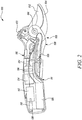
- FIG. 2 illustrates the cutting tool 100 which includes a drive unit 130.
- the drive unit 130 includes a motor 112 and a gearbox 114.
- the drive unit 130 further includes a drum 116 comprising a clutch, a retraction spring and a winch.
- the drive unit 130 includes a printed circuit board assembly (PCBA) 118 and a battery 120.
- the battery 120 is covered by the lid 132.
- the lid 132 may be slide opened to change the battery 120.
- the drive unit 130 is operatively coupled to at least one of the first blade 102 and the second blade 104.
- the drive unit 130 is housed within the second handle 110.
- the battery 120 of the drive unit 130 is also housed within the second handle 110. This helps in reducing the dimensions and improving ergonomic profile of the first handle 108.
- the drive unit 130 is configured to selectively provide a supplemental motor force to assist a movement of at least one of the first blade 102 and the second blade 104 to perform the cutting action.
- a wire 134 is running between the first handle 108 and the second handle 110, and the first handle 108 and the second handle 110.
- the wire 134 is connected to the drive unit 130.
- the wire 134 may be a sensor wire detecting a torque between the one or more blades 102, 104 and the one or more handles 108, 110 .
- the wire 134 detects the force applied by the user which is further sent to a drive unit 130 (or say any processer of the cutting tool 100 ) to take the applied force into account to assist with any supplemental force, as per the need.
- the wire 134 is substantially running through the first handle 108, or any other part/component of the cutting tool 100, in order to make the cutting tool 100 more compact, ergonomic and the like. Some part of the wire 134 may even run through the second handle 110 which allows uniform distribution of the wire 134.
- all components of the drive unit 130 are housed in a single handle i.e. the second handle 110 as best illustrated in FIG. 2 .
- boundary lines (not shown) of both the first handle 108 and the second handle 110 may be parallel to each other. Alternately or additionally, the boundary lines of the one or more of handles i.e. the first handle 108 and the second handle 110 may be non-aligned with respect to each other.
- the cutting tool 100 could also include a switch to activate or deactivate the drive unit 130.
- this switch is realized in top of the cutting tool 100 as slider or trigger 122, alternatively it as well could be realized as a slider of trigger.
- the drive unit 130 gets switched on and off and thus the cutting tool 100 becomes convenient and safe to handle by common users.
- the drive unit 130 may be deactivated for instances which may require to save/extend battery life or allow uninterrupted operation of the power-assisted cutting tool 100, such as for low battery conditions. In such instances of the deactivated drive unit 130, it could be possible that the motor 112 will remain in a disengaged/OFF state leading to a purely user-based cutting action by the cutting tool 100, without any supplemental motor force.
- the slider or trigger 122 may be a button, a knob, a single pole single throw switch, a single pole double throw switch, a double pole single throw switch, a double pole double throw switch, a push-button switch, a toggle switch, a limit switch, a float switch, and the like.
- a button, a knob, or any other switching means as used or known in the relevant art may be present in place of the slider or trigger 122.
- the battery 120 may be a primary battery, a secondary battery.
- the battery 120 may be one or more of a lithiumion, a nickel cadmium, a nickel-metal hydride, and a lead-acid battery.
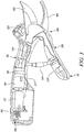
- FIG. 3 illustrates the first handle 108 and the second handle 110 which have one or more inner sides 115, 117 respectively.
- elastic, rounded design of the one or more inner sides 115,117 of both the first handle 108 and the second handle 110 may allow to avoid an undesirable crushing, in particular a pinching of operator's or user's hand, between the first handle 108 and the second handle 110, and the like.
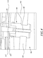
- FIG. 4 illustrates an adapter 128 of the cutting tool 100.
- the cutting tool 100 further includes a rope 126 and a spring 124.
- the adapter 128 finds application for pre-fixing the spring 124 and the rope 126 with the first handle 110, without any direct engagement or contact of the spring 124 and the rope 126 with the first handle 110.
- the first blade 102 is passing through the adapter 128.
- the piercing of the first blade 102 through the adapter 128 helps in securing or locking of the first blade 102 within the adapter 128, and/or the bottom handle 110 as per the requirement.
- a connection of the adapter 128 with the first blade 102 may be achieved by pushing, sliding, and piercing the first blade 102 through the adapter 128.
- the adapter 128 may be made up of one or more of a material like plastic, rubber, glass and the like. Additionally, or alternatively, the first blade 102 may slide, pierce, pass into the adapter 128.
- the adapter 128 allows the smooth movement or disassembly of the first blade 102 by simple pulling action on the first blade 102.
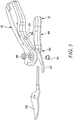
- FIG. 5 illustrates the cutting tool 100 which includes a fastener 106 .
- the fastener 106 is provided at the pivoted position of the first blade 102 and the second blade 104.
- the fastener 106 pivotally couples the first handle 108 and the second handle 110.
- the fastener 106 helps in associating the first handle 108 and the second handle 110 together.
- the fastener 106 allows ejection of the first blade 102, on disassembly of the fastener 106.
- the first blade 102 may be substituted with a new blade (i.e. another first blade 102, not shown) having the desired features.
- the fastener 106 may be any one or more of a coupling nut, a flange nut, a hex nut, a lock nut, a slotted nut, a square nut, a wheel nut and the like.
- FIG. 6 illustrates a form fit 136 provided at the point of pivot between the first handle 108 and the second handle 110.
- the form fit 136 allows to avoid inadvertent disassociation of the first handle 108 and the second handle 110 even after the removal of the fastener 106.
- the form fit 136 is a removable connection.
- the form fit 136 helps to isolate the first handle 108 and the second handle 110 from any stresses, damages, or inadvertent force which could have led to disassembly of the first handle 108 and the second handle 110, in absence of the form fit 136 on disassembly of the fastener 106.
- the form fit 136 is formed by one or more tabs 138 provided with at least one of the first handle 108 and the second handle 110.
- the one or more tabs 138 are provided with the first handle 108.
- the one or more tabs 138 couple with one or more contours 140 provided with the second handle 110. Alternately, position of the one or more tabs 138 and the one or more contours 140 may be exchanged between the first handle 108 and the second handle 110.
- This coupling of the one or more tabs 138 and the one or more contours 140 of the form fit 136 prevents inadvertent dissociation of the first handle 108 and the second handle 110, such as during removal or disassembly of any of the first blade 102 and the second blade 104.
- the form fit 136 with the first blade 102, and the second blade 104 may be provided as an integral structural feature of the first blade 102 and the second blade 104.
- the form fit 136 may also be provided by attaching the tabs 138 through gluing, tying, screwing and the like.
- the one or more blades i.e. the first blade 102 and the second blade 104, and the form fit 136 may be coupled together by using snap-fits, push-fits, or by connections like threads and the like.
- the form fit 136 may be removably disassociated as per the requirements. The form fit 136 helps the wire 134 to retain its stability without disturbing any functionality of the cutting tool 100.
Landscapes
- Life Sciences & Earth Sciences (AREA)
- Forests & Forestry (AREA)
- Engineering & Computer Science (AREA)
- Mechanical Engineering (AREA)
- Biodiversity & Conservation Biology (AREA)
- Ecology (AREA)
- Environmental Sciences (AREA)
- Scissors And Nippers (AREA)
Abstract
A cutting tool (100) includes a first blade (102) and a second blade (104). The second blade (104) is pivotally coupled at a pivot point to the first blade (102). The first blade (102) and the second blade (104) together perform a cutting action on an object placed between them. The cutting tool (100) further includes a first handle (108) and a second handle (110). The first handle (108) is operatively coupled to the first blade (102). The second handle (110) is operatively coupled to the second blade (104). The first handle (108) is pivotally coupled to the second handle (110) at the pivot point through a form fit (136).
Description
- The present disclosure relates to a cutting tool. More specifically, the present disclosure relates to the cutting tool which allows safe and user-friendling handling and disassembly of blades of the cutting tool.
- Cutting tools such as secateurs, loppers, rakes, pliers are used for performing cutting action using one or more blades. Put simply, such tools provide increased mechanical assistance and ease of operation to a common user to conveniently perform operations such as with branches of varying dimensions. Further, the cutting tools provide benefits such as trapping bypass cutting or simply "bypass" allows pruning/cutting by the cutting tools while holding an object (i.e. branch) with one of the cutting edges.
- However, there may be many instances where working with the cutting tool becomes inconvenient and unsafe for a user to handle. For instance, on unbolting a removeable nut provided at a pivoted point of one or more blades and one or more handles of the cutting tools, there are chances of the one or more handles to inadvertently disassemble during blade(s) replacement. This segregation of the one or more handles may deform structure of the cutting tool or pose hindrances or even damage to some accessories (say wires) assembled within the one or more handles.
- An example of a cutting tool is provided in
US patent application 10, 076, 827 - Thus, there is a need of an improved cutting tool which allows ease of disassembly of blades without inadvertently disturbing handles or other parts of the cutting tool.
- In view of the above, it is an objective of the present invention to solve or at least reduce the drawbacks discussed above. The objective is at least partially achieved by a cutting tool. The cutting tool includes a first blade and a second blade. The second blade is pivotally coupled to the first blade at a pivot point. The first blade and the second blade together perform a cutting action on an object placed between them. The cutting tool further includes a first handle and a second handle. The first handle is operatively coupled to the first blade. The second handle is operatively coupled to the second blade. The cutting tool is characterized in that the first handle is pivotally coupled to the second handle at the pivot point, while the first handle and the second handle are pivotally coupled together through a form fit. Thus, the present disclosure provides a simple, convenient, and user-friendly cutting tool which allows ease of blade(s) replacement without hampering or distorting handle(s) or other parts, in particular the wire electrically connecting electrical components located within the different handles, of the cutting tool inadvertently.
- According to an embodiment of the present invention, a fastener pivotally couples the first blade and the second blade. The fastener helps in removable and user-friendly coupling of the first blade and the second blade.
- According to an embodiment of the present invention, the form fit is realized via a snap fit connection. The form fit allows to avoid inadvertent disassociation of the first handle and the second handle, even after the removal of the fastener.
- According to an embodiment of the present invention, the form fit is a removable connection. The form fit helps in isolation of the first handle and the second handle as per requirements.
- According to an embodiment of the present invention electrical components associated with the
first handle 108 and within thesecond handle 110 are electrically connected via awire 134. This allows to easily associate various different electrical components of the cutting tool with different ones of the two handles. In a preferred embodiments at least some of the associated components are incorporated inside of at least one of the handles, which allows to enhance their protection as well as to optimize the ergonomics of the handles. - According to an embodiment of the present invention, the wire is a sensor wire. The sensor wire detects the force applied by the user which is further sent to a drive unit (or processor) to take the applied force into account for providing mechanical advantage, if required.
- According to an embodiment of the present invention, the sensor wire is present substantially within the first handle. Some part of the sensor wire is also running through the second handle. This makes the arrangement of the cutting tool more compact, ergonomic and helps in uniform distribution of the wire.
- Other features and aspects of this invention will be apparent from the following description and the accompanying drawings.
- The invention will be described in more detail with reference to the enclosed drawings, wherein:
-
FIG. 1 shows a perspective view of a cutting tool, in accordance with an aspect of the present disclosure; -
FIG. 2 shows a perspective view of a drive unit within the cutting tool, in accordance with an aspect of the present disclosure; -
FIG. 3 shows a perspective view of the cutting tool, in accordance with another aspect of the present disclosure -
FIG. 4 shows a perspective view of an adapter of the cutting tool, in accordance with an aspect of the present disclosure; -
FIG. 5 shows a perspective view of the cutting tool showing disassembly of a fastener, in accordance with another aspect of the present disclosure; and -
FIG. 6 shows a perspective view of a form fit connection of a first handle and a second handle of the cutting tool, in accordance with an aspect of the present disclosure. - The present invention will be described more fully hereinafter with reference to the accompanying drawings, in which example embodiments of the invention incorporating one or more aspects of the present invention are shown. This invention may, however, be embodied in many different forms and should not be construed as limited to the embodiments set forth herein; rather, these embodiments are provided so that this disclosure will be thorough and complete, and will fully convey the scope of the invention to those skilled in the art. For example, one or more aspects of the present invention may be utilized in other embodiments and even other types of structures and/or methods. In the drawings, like numbers refer to like elements.
- Certain terminology is used herein for convenience only and is not to be taken as a limitation on the invention. For example, "upper", "lower", "front", "rear", "side", "longitudinal", "lateral", "transverse", "upwards", "downwards", "forward", "backward", "sideward", "left," "right," "horizontal," "vertical," "upward", "inner", "outer", "inward", "outward", "top", "bottom", "higher", "above", "below", "central", "middle", "intermediate", "between", "end", "adjacent", "proximate", "near", "distal", "remote", "radial", "circumferential", or the like, merely describe the configuration shown in the Figures. Indeed, the components may be oriented in any direction and the terminology, therefore, should be understood as encompassing such variations unless specified otherwise.
-
FIG. 1 illustrates acutting tool 100. Thecutting tool 100 of the present disclosure is illustrated as secateurs, however, the present disclosure may be readily applied to anycutting tool 100 such as, but not limited to, a lopper, shears, scissors etc. with two or more cutting edges. Thecutting tool 100 includes one or more blades i.e. afirst blade 102 and asecond blade 104. Thefirst blade 102 is a replaceable blade. Further, thesecond blade 104 is pivotally coupled to thefirst blade 102. Thefirst blade 102 and thesecond blade 104 together perform a cutting action on an object (generally a branch) placed between them. In one embodiment thecutting tool 100 further includes alid 132. This allows for an easy replacement of the battery. Preferably the cutting tool is using a replaceable battery or even uses different ones out of a set of replaceable batteries. - As illustrated in
FIG. 1 , thecutting tool 100 includes one or more handles i.e. afirst handle 108 and asecond handle 110. Thefirst handle 108 is operatively coupled with thefirst blade 102. Further, thefirst handle 108 defines atop portion 109 and aback portion 111. Thesecond handle 110 is operatively coupled with thesecond blade 104. In closed position of thecutting tool 100, at least a part of thesecond handle 110 at least partially encloses theback portion 111 of thefirst handle 108. Although, the present embodiment illustrates thefirst handle 108 almost fully enclosed within thesecond handle 110, thesecond handle 110 may also be at least partially enclosed within thesecond handle 110. - In some embodiments, the
first blade 102 and thesecond blade 104 may be one or more of a clip point blade, a drop point blade, a gut hook blade, a hawkbell blade, a needle point blade, a straight back blade, a sheepsfoot blade and a spear point blade. - In some embodiments, the
first blade 102 and thesecond blade 104 may be made of aluminum or any other material as used or known in the art. Choice of the material for any of thefirst blade 102 and thesecond blade 104 will generally depend upon factors such as life, application, weight or other parameters related to thecutting tool 100. However, the present disclosure is not to be limited by the type of material of thefirst blade 102 and thesecond blade 104 in any manner. - During implementation, at least one of the
first blade 102 and thesecond blade 104 may be a fixed blade while the other performs desired cutting action. Alternately or additionally, both thefirst blade 102 and thesecond blade 104 may be movable during the cutting action. -
FIG. 2 illustrates thecutting tool 100 which includes adrive unit 130. Thedrive unit 130 includes amotor 112 and agearbox 114. Thedrive unit 130 further includes adrum 116 comprising a clutch, a retraction spring and a winch. Further, thedrive unit 130 includes a printed circuit board assembly (PCBA) 118 and abattery 120. In one embodiment thebattery 120 is covered by thelid 132. Thelid 132 may be slide opened to change thebattery 120. Thedrive unit 130 is operatively coupled to at least one of thefirst blade 102 and thesecond blade 104. As illustrated in the present embodiment, thedrive unit 130 is housed within thesecond handle 110. Thebattery 120 of thedrive unit 130 is also housed within thesecond handle 110. This helps in reducing the dimensions and improving ergonomic profile of thefirst handle 108. Thedrive unit 130 is configured to selectively provide a supplemental motor force to assist a movement of at least one of thefirst blade 102 and thesecond blade 104 to perform the cutting action. - As illustrated in
FIG. 2 , awire 134 is running between thefirst handle 108 and thesecond handle 110, and thefirst handle 108 and thesecond handle 110. Thewire 134 is connected to thedrive unit 130. In some embodiments, thewire 134 may be a sensor wire detecting a torque between the one ormore blades more handles wire 134 detects the force applied by the user which is further sent to a drive unit 130 (or say any processer of the cutting tool 100) to take the applied force into account to assist with any supplemental force, as per the need. In some embodiments, thewire 134 is substantially running through thefirst handle 108, or any other part/component of thecutting tool 100, in order to make thecutting tool 100 more compact, ergonomic and the like. Some part of thewire 134 may even run through thesecond handle 110 which allows uniform distribution of thewire 134. - In a preferred embodiment, all components of the
drive unit 130 are housed in a single handle i.e. thesecond handle 110 as best illustrated inFIG. 2 . This helps in reducing the thickness, dimensions, ergonomic profile or spatial footprint of thesecond handle 110, and thefirst handle 108. This even allows the combined profile of thesecond handle 110, and thefirst handle 108 to be realized as one part, particularly during closed state of thefirst handle 108. - In some embodiments, boundary lines (not shown) of both the
first handle 108 and thesecond handle 110 may be parallel to each other. Alternately or additionally, the boundary lines of the one or more of handles i.e. thefirst handle 108 and thesecond handle 110 may be non-aligned with respect to each other. - In some embodiments, the
cutting tool 100 could also include a switch to activate or deactivate thedrive unit 130. In the depicted embodiment this switch is realized in top of thecutting tool 100 as slider or trigger 122, alternatively it as well could be realized as a slider of trigger. On engaging, moving or pressing the slider or trigger 122 thedrive unit 130 gets switched on and off and thus thecutting tool 100 becomes convenient and safe to handle by common users. Thedrive unit 130 may be deactivated for instances which may require to save/extend battery life or allow uninterrupted operation of the power-assistedcutting tool 100, such as for low battery conditions. In such instances of the deactivateddrive unit 130, it could be possible that themotor 112 will remain in a disengaged/OFF state leading to a purely user-based cutting action by thecutting tool 100, without any supplemental motor force. - In some embodiments, the slider or trigger 122 may be a button, a knob, a single pole single throw switch, a single pole double throw switch, a double pole single throw switch, a double pole double throw switch, a push-button switch, a toggle switch, a limit switch, a float switch, and the like. Alternately or additionally, a button, a knob, or any other switching means as used or known in the relevant art may be present in place of the slider or
trigger 122. - In some embodiments, the
battery 120 may be a primary battery, a secondary battery. For example, thebattery 120 may be one or more of a lithiumion, a nickel cadmium, a nickel-metal hydride, and a lead-acid battery. -
FIG. 3 illustrates thefirst handle 108 and thesecond handle 110 which have one or moreinner sides first handle 108 and thesecond handle 110 may allow to avoid an undesirable crushing, in particular a pinching of operator's or user's hand, between thefirst handle 108 and thesecond handle 110, and the like. -
FIG. 4 illustrates anadapter 128 of thecutting tool 100. Thecutting tool 100 further includes arope 126 and aspring 124. Theadapter 128 finds application for pre-fixing thespring 124 and therope 126 with thefirst handle 110, without any direct engagement or contact of thespring 124 and therope 126 with thefirst handle 110. Thefirst blade 102 is passing through theadapter 128. The piercing of thefirst blade 102 through theadapter 128 helps in securing or locking of thefirst blade 102 within theadapter 128, and/or thebottom handle 110 as per the requirement. - In some embodiments, a connection of the
adapter 128 with thefirst blade 102 may be achieved by pushing, sliding, and piercing thefirst blade 102 through theadapter 128. Theadapter 128 may be made up of one or more of a material like plastic, rubber, glass and the like. Additionally, or alternatively, thefirst blade 102 may slide, pierce, pass into theadapter 128. Theadapter 128 allows the smooth movement or disassembly of thefirst blade 102 by simple pulling action on thefirst blade 102. -
FIG. 5 illustrates thecutting tool 100 which includes a fastener106. Thefastener 106 is provided at the pivoted position of thefirst blade 102 and thesecond blade 104. Thefastener 106 pivotally couples thefirst handle 108 and thesecond handle 110. In this configuration, thefastener 106 helps in associating thefirst handle 108 and thesecond handle 110 together. Moreover, thefastener 106 allows ejection of thefirst blade 102, on disassembly of thefastener 106. Thefirst blade 102 may be substituted with a new blade (i.e. anotherfirst blade 102, not shown) having the desired features. - In some embodiments, the
fastener 106 may be any one or more of a coupling nut, a flange nut, a hex nut, a lock nut, a slotted nut, a square nut, a wheel nut and the like. -
FIG. 6 illustrates aform fit 136 provided at the point of pivot between thefirst handle 108 and thesecond handle 110. The form fit 136 allows to avoid inadvertent disassociation of thefirst handle 108 and thesecond handle 110 even after the removal of thefastener 106. In a preferred embodiment, theform fit 136 is a removable connection. The form fit 136 helps to isolate thefirst handle 108 and thesecond handle 110 from any stresses, damages, or inadvertent force which could have led to disassembly of thefirst handle 108 and thesecond handle 110, in absence of the form fit 136 on disassembly of thefastener 106. - In the present embodiment, the
form fit 136 is formed by one ormore tabs 138 provided with at least one of thefirst handle 108 and thesecond handle 110. In the illustrated embodiments, the one ormore tabs 138 are provided with thefirst handle 108. The one ormore tabs 138 couple with one ormore contours 140 provided with thesecond handle 110. Alternately, position of the one ormore tabs 138 and the one ormore contours 140 may be exchanged between thefirst handle 108 and thesecond handle 110. This coupling of the one ormore tabs 138 and the one ormore contours 140 of theform fit 136 prevents inadvertent dissociation of thefirst handle 108 and thesecond handle 110, such as during removal or disassembly of any of thefirst blade 102 and thesecond blade 104. - During implementation, the form fit 136 with the
first blade 102, and thesecond blade 104 may be provided as an integral structural feature of thefirst blade 102 and thesecond blade 104. The form fit 136 may also be provided by attaching thetabs 138 through gluing, tying, screwing and the like. Alternately or additionally, the one or more blades i.e. thefirst blade 102 and thesecond blade 104, and theform fit 136 may be coupled together by using snap-fits, push-fits, or by connections like threads and the like. Further, theform fit 136 may be removably disassociated as per the requirements. The form fit 136 helps thewire 134 to retain its stability without disturbing any functionality of thecutting tool 100. - In the drawings and specification, there have been disclosed preferred embodiments and examples of the invention and, although specific terms are employed, they are used in a generic and descriptive sense only and not for the purpose of limitation of the scope of the invention being set forth in the following claims.
-
- 100
- Cutting Tool
- 102
- First blade
- 104
- Second blade
- 106
- Fastener
- 108
- First handle
- 109
- Top Portion
- 110
- Second handle
- 111
- Back Portion
- 112
- Motor
- 114
- Gear Box
- 115
- Inner Side
- 116
- Drum
- 117
- Inner Side
- 118
- Printed Circuit Board Assembly (PCBA)
- 120
- Battery
- 122
- Slider or Trigger
- 130
- Drive unit
- 132
- Lid
- 134
- wire
- 136
- Form fit
- 138
- Tabs
- 140
- Contours
Claims (8)
- A cutting tool (100) comprising:a first blade (102);a second blade (104) pivotally coupled to the first blade (102) at a pivot point, wherein the first blade (102) and the second blade (104) together perform a cutting action on an object placed therebetween;a first handle (108) operatively coupled to the first blade (102);a second handle (110) operatively coupled to the second blade (104),characterized in that:the first handle (108) is pivotally coupled to the second handle (110) at the pivot point;the first handle (108) and the second handle (110) are pivotally coupled together through a form fit (136).
- The cutting tool (100) of claim 1, wherein a fastener (110) pivotally couples the first blade (102) and the second blade (104) at the pivot point.
- The cutting tool (100) of claim 1, wherein the form fit (136) is realized via a snap fit connection (136).
- The cutting tool (100) of claim 1, wherein the form fit (136) is a removable connection.
- The cutting tool (100) of claim 1, wherein electrical components associated with the first handle (108) and within the second handle (110) are electrically connected via a wire (134).
- The cutting tool (100) of claim 5, wherein at least some of the associated components are incorporated inside of at least one of the handles (108, 110).
- The cutting tool (100) of claim 5 or 6, wherein the wire (134) is a sensor wire (134).
- The cutting tool (100) of claim 7, wherein the sensor wire (134) is present substantially within the first handle (108).
Priority Applications (6)
| Application Number | Priority Date | Filing Date | Title |
|---|---|---|---|
| EP20154316.2A EP3858562A1 (en) | 2020-01-29 | 2020-01-29 | Cutting tool |
| FIEP20810996.7T FI4096879T3 (en) | 2020-01-29 | 2020-11-26 | Cutting tool |
| PL20810996.7T PL4096879T3 (en) | 2020-01-29 | 2020-11-26 | Cutting tool |
| CN202080095009.9A CN115023323B (en) | 2020-01-29 | 2020-11-26 | cutting tools |
| EP20810996.7A EP4096879B1 (en) | 2020-01-29 | 2020-11-26 | Cutting tool |
| PCT/EP2020/083462 WO2021151548A1 (en) | 2020-01-29 | 2020-11-26 | Cutting tool |
Applications Claiming Priority (1)
| Application Number | Priority Date | Filing Date | Title |
|---|---|---|---|
| EP20154316.2A EP3858562A1 (en) | 2020-01-29 | 2020-01-29 | Cutting tool |
Publications (1)
| Publication Number | Publication Date |
|---|---|
| EP3858562A1 true EP3858562A1 (en) | 2021-08-04 |
Family
ID=69400410
Family Applications (2)
| Application Number | Title | Priority Date | Filing Date |
|---|---|---|---|
| EP20154316.2A Withdrawn EP3858562A1 (en) | 2020-01-29 | 2020-01-29 | Cutting tool |
| EP20810996.7A Active EP4096879B1 (en) | 2020-01-29 | 2020-11-26 | Cutting tool |
Family Applications After (1)
| Application Number | Title | Priority Date | Filing Date |
|---|---|---|---|
| EP20810996.7A Active EP4096879B1 (en) | 2020-01-29 | 2020-11-26 | Cutting tool |
Country Status (5)
| Country | Link |
|---|---|
| EP (2) | EP3858562A1 (en) |
| CN (1) | CN115023323B (en) |
| FI (1) | FI4096879T3 (en) |
| PL (1) | PL4096879T3 (en) |
| WO (1) | WO2021151548A1 (en) |
Cited By (2)
| Publication number | Priority date | Publication date | Assignee | Title |
|---|---|---|---|---|
| US12127512B2 (en) * | 2016-10-17 | 2024-10-29 | Robert Bosch Gmbh | Cutting device |
| US12589512B2 (en) * | 2023-12-28 | 2026-03-31 | Toyota Motor Engineering & Manufacturing North America, Inc. | Shearing tool with closure assist |
Citations (5)
| Publication number | Priority date | Publication date | Assignee | Title |
|---|---|---|---|---|
| US5353504A (en) * | 1993-04-30 | 1994-10-11 | Pai Chung Jen | Motorized scissors |
| US20090151170A1 (en) * | 2007-12-18 | 2009-06-18 | Corona Clipper, Inc. | Multi-function hand operated pruning clippers |
| US20110016730A1 (en) * | 2009-07-21 | 2011-01-27 | Shih-Piao Wu | Pruning Hook with Two Operation Modes |
| US10076827B2 (en) | 2008-06-11 | 2018-09-18 | Quic Industries, Inc. | Hand tool and method of using same |
| WO2018205126A1 (en) * | 2017-05-09 | 2018-11-15 | Tti (Macao Commercial Offshore) Limited | A power tool and a driving mechanism for use in a power tool |
Family Cites Families (5)
| Publication number | Priority date | Publication date | Assignee | Title |
|---|---|---|---|---|
| JP3407122B2 (en) * | 1995-03-17 | 2003-05-19 | アルスコーポレーション株式会社 | Replaceable blade scissors |
| US5946752A (en) * | 1997-01-15 | 1999-09-07 | Fiskars Inc. | Spring biased implement for use in multi-function tools |
| TW454653U (en) * | 2000-11-03 | 2001-09-11 | Jang Shiue Chin | Spring clip for both inner and outer C-typed clips |
| FI124699B (en) * | 2011-06-30 | 2014-12-15 | Iittala Group Oy Ab | Cutting Tools |
| FR3034285B1 (en) * | 2015-04-01 | 2017-03-17 | Pellenc Sa | DEVICE FOR MAINTAINING A SWIVEL CUTTING BLADE |
-
2020
- 2020-01-29 EP EP20154316.2A patent/EP3858562A1/en not_active Withdrawn
- 2020-11-26 WO PCT/EP2020/083462 patent/WO2021151548A1/en not_active Ceased
- 2020-11-26 CN CN202080095009.9A patent/CN115023323B/en active Active
- 2020-11-26 PL PL20810996.7T patent/PL4096879T3/en unknown
- 2020-11-26 FI FIEP20810996.7T patent/FI4096879T3/en active
- 2020-11-26 EP EP20810996.7A patent/EP4096879B1/en active Active
Patent Citations (5)
| Publication number | Priority date | Publication date | Assignee | Title |
|---|---|---|---|---|
| US5353504A (en) * | 1993-04-30 | 1994-10-11 | Pai Chung Jen | Motorized scissors |
| US20090151170A1 (en) * | 2007-12-18 | 2009-06-18 | Corona Clipper, Inc. | Multi-function hand operated pruning clippers |
| US10076827B2 (en) | 2008-06-11 | 2018-09-18 | Quic Industries, Inc. | Hand tool and method of using same |
| US20110016730A1 (en) * | 2009-07-21 | 2011-01-27 | Shih-Piao Wu | Pruning Hook with Two Operation Modes |
| WO2018205126A1 (en) * | 2017-05-09 | 2018-11-15 | Tti (Macao Commercial Offshore) Limited | A power tool and a driving mechanism for use in a power tool |
Cited By (2)
| Publication number | Priority date | Publication date | Assignee | Title |
|---|---|---|---|---|
| US12127512B2 (en) * | 2016-10-17 | 2024-10-29 | Robert Bosch Gmbh | Cutting device |
| US12589512B2 (en) * | 2023-12-28 | 2026-03-31 | Toyota Motor Engineering & Manufacturing North America, Inc. | Shearing tool with closure assist |
Also Published As
| Publication number | Publication date |
|---|---|
| EP4096879A1 (en) | 2022-12-07 |
| FI4096879T3 (en) | 2024-02-01 |
| PL4096879T3 (en) | 2024-03-25 |
| EP4096879B1 (en) | 2023-12-20 |
| CN115023323A (en) | 2022-09-06 |
| CN115023323B (en) | 2023-12-22 |
| WO2021151548A1 (en) | 2021-08-05 |
Similar Documents
| Publication | Publication Date | Title |
|---|---|---|
| US20250366404A1 (en) | Cutting tool | |
| US8276280B2 (en) | Electromotion trim scissors | |
| EP2759189B1 (en) | Vegetation trimmer | |
| US8136254B2 (en) | Split power tool with extension | |
| EP4096879B1 (en) | Cutting tool | |
| EP3694303B1 (en) | Handheld tool for single-handed operation | |
| WO2008097579A1 (en) | Split power tool | |
| US20200245549A1 (en) | Gardening Tool | |
| KR101083191B1 (en) | an pruning shears of gardening required various function | |
| TWI817936B (en) | Handheld tool | |
| EP3858133A1 (en) | Cutting tool | |
| CN210157698U (en) | High branch scissors | |
| EP4096880B1 (en) | Cutting tool | |
| KR200344119Y1 (en) | Automatic pruning shears | |
| EP4062746A1 (en) | Cutting tool | |
| CN116214652B (en) | Cutting device is got with pressing from both sides to forestry rattan | |
| CN221082109U (en) | Multifunctional pruning tool for pomegranate planting | |
| KR20240133461A (en) | Pepper Automatic Harvester | |
| JP2021073939A (en) | Mower | |
| CN202172590U (en) | Grass cutter | |
| EP1743517A1 (en) | Powered tool |
Legal Events
| Date | Code | Title | Description |
|---|---|---|---|
| PUAI | Public reference made under article 153(3) epc to a published international application that has entered the european phase |
Free format text: ORIGINAL CODE: 0009012 |
|
| STAA | Information on the status of an ep patent application or granted ep patent |
Free format text: STATUS: THE APPLICATION HAS BEEN PUBLISHED |
|
| AK | Designated contracting states |
Kind code of ref document: A1 Designated state(s): AL AT BE BG CH CY CZ DE DK EE ES FI FR GB GR HR HU IE IS IT LI LT LU LV MC MK MT NL NO PL PT RO RS SE SI SK SM TR |
|
| STAA | Information on the status of an ep patent application or granted ep patent |
Free format text: STATUS: THE APPLICATION IS DEEMED TO BE WITHDRAWN |
|
| 18D | Application deemed to be withdrawn |
Effective date: 20220205 |