EP3858504A1 - Heat-retaining rolling equipment - Google Patents
Heat-retaining rolling equipment Download PDFInfo
- Publication number
- EP3858504A1 EP3858504A1 EP19877729.4A EP19877729A EP3858504A1 EP 3858504 A1 EP3858504 A1 EP 3858504A1 EP 19877729 A EP19877729 A EP 19877729A EP 3858504 A1 EP3858504 A1 EP 3858504A1
- Authority
- EP
- European Patent Office
- Prior art keywords
- panel
- frame
- heat keeping
- cover
- keeping apparatus
- Prior art date
- Legal status (The legal status is an assumption and is not a legal conclusion. Google has not performed a legal analysis and makes no representation as to the accuracy of the status listed.)
- Granted
Links
Images




Classifications
-
- B—PERFORMING OPERATIONS; TRANSPORTING
- B21—MECHANICAL METAL-WORKING WITHOUT ESSENTIALLY REMOVING MATERIAL; PUNCHING METAL
- B21B—ROLLING OF METAL
- B21B45/00—Devices for surface or other treatment of work, specially combined with or arranged in, or specially adapted for use in connection with, metal-rolling mills
- B21B45/008—Heat shields
-
- B—PERFORMING OPERATIONS; TRANSPORTING
- B21—MECHANICAL METAL-WORKING WITHOUT ESSENTIALLY REMOVING MATERIAL; PUNCHING METAL
- B21B—ROLLING OF METAL
- B21B2203/00—Auxiliary arrangements, devices or methods in combination with rolling mills or rolling methods
- B21B2203/12—Covers or shieldings
-
- B—PERFORMING OPERATIONS; TRANSPORTING
- B21—MECHANICAL METAL-WORKING WITHOUT ESSENTIALLY REMOVING MATERIAL; PUNCHING METAL
- B21B—ROLLING OF METAL
- B21B37/00—Control devices or methods specially adapted for metal-rolling mills or the work produced thereby
- B21B37/74—Temperature control, e.g. by cooling or heating the rolls or the product
- B21B37/76—Cooling control on the run-out table
-
- Y—GENERAL TAGGING OF NEW TECHNOLOGICAL DEVELOPMENTS; GENERAL TAGGING OF CROSS-SECTIONAL TECHNOLOGIES SPANNING OVER SEVERAL SECTIONS OF THE IPC; TECHNICAL SUBJECTS COVERED BY FORMER USPC CROSS-REFERENCE ART COLLECTIONS [XRACs] AND DIGESTS
- Y02—TECHNOLOGIES OR APPLICATIONS FOR MITIGATION OR ADAPTATION AGAINST CLIMATE CHANGE
- Y02P—CLIMATE CHANGE MITIGATION TECHNOLOGIES IN THE PRODUCTION OR PROCESSING OF GOODS
- Y02P70/00—Climate change mitigation technologies in the production process for final industrial or consumer products
- Y02P70/10—Greenhouse gas [GHG] capture, material saving, heat recovery or other energy efficient measures, e.g. motor control, characterised by manufacturing processes, e.g. for rolling metal or metal working
Definitions
- the present disclosure relates to a heat keeping apparatus for a rolling transfer line capable of enhancing a heat keeping effect by changing the shape of a heat keeping cover depending on the size of a material to be transferred.
- a material for rolling is heated to approximately 1300 ⁇ 1400°C in a heating furnace and then transferred to a rough rolling process. As the heated material goes through the rough rolling process, a temperature thereof drops to approximately 900 ⁇ 1100°C due to the influence of cooling water or the atmosphere, and a length thereof increases, resulting in a temperature deviation in a longitudinal direction.
- the material that has gone through the rough rolling process is transferred to a finish rolling process along a transfer line (roller table) of about 100 meters.
- a transfer line roll table
- an additional temperature drop occurs in the material due to air cooling.
- the temperature difference between a front end and a rear end of the material further increases based on a time point of rolling in the finish rolling process.
- a time difference between a time point when the front end of the material is rolled and a time point when the rear end of the material is rolled reaches tens of seconds. Accordingly, a temperature when the rear end of the material is rolled is approximately 50°C lower than a temperature when the front end of the material is rolled.
- a heat keeping apparatus may be installed on a rolling transfer line to keep heat of a material by covering the outside of the material being transferred with a heat keeping cover.
- the heat keeping cover reduces the temperature drop at the rear end of the material by keeping the heat of the material being transferred.
- the present disclosure is directed to providing a rolling heat keeping apparatus capable of enhancing a heat keeping effect by changing the shape of a heat keeping cover depending on the size of a material to be transferred.
- the present disclosure is directed to providing a rolling heat keeping apparatus capable of easy maintenance of a reflective panel and preventing bending of the reflective panel by allowing thermal deformation of the reflective panel.
- An aspect of the present disclosure provides a heat keeping apparatus for a rolling transfer line including a heat keeping cover configured to cover and heat the outside of a material being transferred along the transfer line, wherein the heat keeping cover includes an upper cover part provided to cover an upper side of the material, first and second side cover parts provided to cover sides of the material and rotatably connected to both sides of the upper cover part, and at least one actuacting part provided to adjust unfolding of the first or second side cover part by rotating the first or second side cover part.
- the upper cover part may include an upper frame, a panel support device bufferably mounted on the upper frame, and an upper reflective panel supported by the panel support device to be replaceable and thermally deformable.
- Each of the first and second side cover parts may include a side frame rotatably connected to the upper frame, and a side reflective panel supported by the side frame.
- the heat keeping cover may be provided such that cross-sectional structures of the upper cover part and the first and second side cover parts have an arc shape.
- the panel support device may include a rectangular panel frame provided to accommodate the upper reflective panel and having open upper and lower sides, a plurality of coupling members installed on the panel frame to support a circumference of the upper reflective panel and allow thermal deformation of the upper reflective panel by elastic deformation, and a plurality of buffer connection members provided to bufferably connect the panel frame to the upper frame.
- the panel support device may further include a collision bumper installed below the panel frame to protect the upper reflective panel from collision of the material.
- the collision bumper may be provided to protrude downward of the panel frame, extend in a transferring direction of the material, and have both ends fixed to the panel frame.
- the panel frame may include one or more side slots formed in a size that allows the upper reflective panel to pass through for mounting and thermal deformation of the upper reflective panel.
- Each of the plurality of coupling members may include a coupling groove detachably coupled to a circumference of the upper reflective panel, and an elastic deformation part extending from the coupling groove in a bent state and fixed to the panel frame to allow deformation of the upper reflective panel in a width direction.
- Each of the plurality of buffer connection members may include a coil spring having one side connected to an edge of the panel frame and the other side connected to the upper frame.
- the panel frame may include a reinforcing part provided to cross and connect upper sides or lower sides of the panel frame.
- the upper frame and the side frame may be bent in an arc shape, and the side reflective panel may be fixed to the side frame in a state in which a reflection surface is bent to form an inner curved surface.
- the at least one actuacting part may include a first actuacting part to rotate the first side cover part and a second actuacting part to rotate the second side cover part.
- a heat keeping apparatus for a rolling transfer line because upper reflective panels and side reflective panels are made of a material having a low emissivity and a high reflectance, most of the radiant energy radiated from the material can be quickly reflected toward the material, and because a heat keeping cover has an arc-shaped cross-sectional structure so that the reflected energy can be concentrated on the material, a heat keeping effect of the material can be enhanced compared to a conventional one.
- the heat keeping apparatus for the rolling transfer line because a form of the heat keeping cover can be changed in a manner in which a first side cover part and a second side cover part are folded or unfolded depending on a size of the material to be transferred, the heat keeping effect of the material can be enhanced.
- collision bumpers can protect the upper reflective panels, and a plurality of buffer connection members can absorb the impact, damage to the heat keeping cover can be prevented.
- the upper reflective panels are supported by a plurality of elastically deformable coupling members, and side slots of panel frames allow thermal deformation of the upper reflective panels in a width direction, bending of the upper reflective panels can be prevented in spite of thermal deformation (elongation in the width direction) of the upper reflective panels.
- the upper reflective panels can be mounted or separated through the side slots of the panel frames, and the plurality of coupling members can be elastically deformed and easily coupled, maintenance work such as replacement of the upper reflective panels can be easily performed.
- FIG. 1 is a perspective view showing rolling equipment to which a heat keeping apparatus according to an embodiment of the present disclosure is applied.
- a rolling equipment includes a heating furnace 10 to heat a material for rolling, a roughing mill 30 to roll a material 20 heated in the heating furnace 10, a finishing mill 40 to roll the material 20 rough-rolled, and a transfer line 50 (roller table) to transfer the material 20 from the heating furnace 10 to the roughing mill 30 and transfer the material 20 from the roughing mill 30 to the finishing mill 40.
- a heating furnace 10 to heat a material for rolling
- a roughing mill 30 to roll a material 20 heated in the heating furnace 10
- a finishing mill 40 to roll the material 20 rough-rolled
- a transfer line 50 roller table
- a heat keeping apparatus 100 may be installed on the transfer line 50 between the roughing mill 30 and the finishing mill 40.
- the heat keeping apparatus 100 covers the outside of the material 20 to be transferred to the finishing mill 40 through the roughing mill 30 to prevent an excessive drop in a temperature of the material 20 during a transfer process. This is to reduce the temperature drop of the material 20 entering the finishing mill 40 so that a rear end of the material 20 may be rolled satisfactorily in the finishing mill 40.
- the present embodiment illustrates that the heat keeping apparatus 100 is installed on the transfer line 50 between the roughing mill 30 and the finishing mill 40, but an installation location of the heat keeping apparatus 100 is not limited thereto.
- the heat keeping apparatus 100 may be installed at another location of the rolling equipment to prevent temperature drop of the material 20.
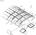
- FIG. 2 is an exploded perspective view of a heat keeping cover of the heat keeping apparatus
- FIGS. 3 and 4 are front views of the heat keeping apparatus, showing states in which first and second side cover parts are unfolded and folded, respectively.
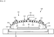
- FIG. 5 is a cross-sectional view of a heat keeping cover.
- the heat keeping apparatus 100 may include a heat keeping cover 101 installed above the transfer line 50 to cover the outside of the material 20 being transferred along the transfer line 50 to keep heat of the material 20, and an opening/closing device 102 capable of raising and lowering the heat keeping cover 101 and opening the heat keeping cover 101 when necessary.
- the heat keeping cover 101 includes an upper cover part 110 to cover an upper portion of the material 20, a first side cover part 120 and a second side cover part 130 rotatably connected to both sides of the upper cover part 110, respectively, to cover both sides of the material 20, a first actuacting part 140 to adjust an unfolding of the first side cover part 120 by rotating the first side cover part 120, and a second actuacting part 150 to adjust an unfolding of the second side cover part 130 by rotating the second side cover part 130.
- the heat keeping cover 101 may form a tunnel having an arc-shaped cross-sectional structure by combining the upper cover part 110, the first side cover part 120, and the second side cover part 130 with each other.
- the tunnel-type heat keeping cover 101 may enhance a heat keeping effect of the material 20 by reflecting the radiant energy radiated from the material 20 toward the material 20 again.
- the first side cover part 120 and the second side cover part 130 may be rotated to unfold to the both sides when the material 20 having a wide width is transferred as shown in FIG. 3 to widen a heat keeping area, and may be rotated to fold inward when a material 20a having a narrow width is transferred as shown in FIG. 4 to narrow the heat keeping area. That is, the heat keeping effect of the materials 20 and 20a may be enhanced by changing the shape of the heat keeping cover 101 to correspond to the size of the materials 20 and 20a to be transferred.
- the upper cover part 110 When the first and second side cover parts 120 and 130 are folded, the upper cover part 110 may be raised, and when the first and second side cover parts 120 and 130 are unfolded, the upper cover part 110 may be lowered.
- the first and second actuacting parts 140 and 150 may be hydraulic cylinders having one side thereof connected to the upper cover part 110 and the other side thereof connected to the first or second side cover part 120 or 130 to adjust an angle by rotating the first or second side cover part 120 or 130 by expansion and contraction.
- the present embodiment illustrates the first actuacting part 140 and the second actuacting part 150 to adjust an angle by actuacting the first side cover part 120 and the second side cover part 130, respectively, but the first side cover part 120 and the second side cover part 130 may be operated simultaneously by one actuacting part. For example, by transmitting power from one actuacting part installed above the upper cover part 110 to the first and second side cover parts 120 and 130, the first and second side cover parts 120 and 130 may rotate simultaneously to be folded or unfolded.
- the upper cover part 110 may include an upper frame 111 formed in an arc shape, a first panel support device 160 and a second panel support device 170 bufferably mounted below the upper frame 111, and a first upper reflective panel 181 and a second upper reflective panel 182 supported by the first and second panel support devices 160 and 170 to be replaceable and thermally deformable.
- the first side cover part 120 and the second side cover part 130 may include side frames 121 and 131 of an arc shape connected to ends of the upper frame 111, and side reflective panels 183 coupled to lower sides of the side frames 121 and 131, respectively.
- a plurality of the upper frames 111 may be disposed to be spaced apart from each other in a transferring direction of the material 20 and may be interconnected by a plurality of connection frames 112 extending in a direction of crossing the upper frames 111.
- a plurality of the side frames 121 and 131 may also be interconnected by a plurality of connection frames 122 in a state of being disposed to be spaced apart from each other in the transferring direction of the material 20.
- One end of the side frames 121 and 131 of the first and second side cover parts 120 and 130 is rotatably connected to both ends of the upper frame 111.
- the first panel support device 160 and the second panel support device 170 are sequentially installed below the upper frame 111 in a lateral direction from the center thereof. Also, the first and second panel support devices 160 and 170 are continuously installed in a longitudinal direction of the heat keeping cover 101 in the same manner.
- FIG. 5 shows only one side of the heat keeping cover 101, but the first and second panel support devices 160 and 170 may be installed to be symmetrical on both sides of the heat keeping cover 101.
- the first panel support device 160 may include a rectangular panel frame 161 accommodating the first upper reflective panel 181 and having open upper and lower sides, a plurality of coupling members 162 installed on the panel frame 161 to support a circumference of the first upper reflective panel 181 and allow thermal deformation of the first upper reflective panel 181 by elastic deformation, and a plurality of buffer connection members 163 to bufferably connect the panel frame 161 to the upper frame 111.
- the first upper reflective panel 181 may have a rectangular panel shape smaller than the panel frame 161 to be accommodated in the panel frame 161.
- the first upper reflective panel 181 may be made of a material such as aluminum, aluminum alloy, zinc oxide, stainless steel that may reflect most of the radiant energy because an emissivity of radiant energy is very low.
- the panel frame 161 includes one or more side slots 164 formed in a size through which the first upper reflective panel 181 may pass.
- the present embodiment illustrates that the side slot 164 is formed on each of four sides of the panel frame 161.
- the side slots 164 allow the first upper reflective panel 181 to be mounted from the sides of the panel frame 161 and may prevent the first upper reflective panel 181 from being bent by receiving deformation generated when the first upper reflective panel 181 is stretched in a width direction due to thermal deformation.
- the plurality of coupling members 162 may be installed in a state of being spaced apart from each other on the panel frame 161 to support the circumference of the first upper reflective panel 181.
- Each of the coupling members 162 may be provided by bending a leaf spring.
- Each of the coupling members 162 may include a coupling groove 162a detachably coupled to the circumference of the first upper reflective panel 181, and an elastic deformation part 162b extending from the coupling groove 162a in a bent state and fixed to the panel frame 161 to allow deformation of the first upper reflective panel 181 in the width direction.
- the circumference of the first upper reflective panel 181 may be maintained in a state of being spaced apart from the panel frame 161 by being supported by the plurality of coupling members 162.
- each of the plurality of buffer connection members 163 may be a coil spring having one side connected to an upper edge of the panel frame 161 and the other side connected to the upper frame 111.
- the present embodiment illustrates a coil spring, but the plurality of buffer connection members 163 may be plate springs capable of elastic deformation.
- the first panel support device 160 may include a collision bumper 165 installed below the panel frame 161 to protect the first upper reflective panel 181 from collision of the material 20.
- the collision bumper 165 may be provided to protrude downward of the panel frame 161, extend long in the transferring direction of the material 20, and have both ends fixed to a lower end of the panel frame 161.
- the panel frame 161 may include reinforcing parts 166a and 166b provided to connect upper or lower sides of the panel frame 161 to each other.
- the reinforcing parts 166a and 166b may reinforce the panel frame 161 by crossing and connecting the upper or lower sides of the panel frame 161 in the direction in which the material 20 is transferred.
- the second panel support device 170 may also be provided similarly to the first panel support device 160.
- the second panel support device 170 may also include a rectangular panel frame 171 to accommodate and support the second upper reflective panel 182, a plurality of coupling members 172, a plurality of buffer connection members 173, and a collision bumper 175.
- the second panel support device 170 may be provided such that a thickness of the panel frame 171 gradually decreases in a lateral direction so that the second panel support device 170 may be mounted corresponding to a curvature of the arc-shaped upper frame 111.
- the second upper reflective panel 182 may also be made of the same material as the first upper reflective panel 181 and installed on the panel frame 171 in a similar manner to the first upper reflective panel 181.
- the side reflective panels 183 installed on the first and second side cover parts 120 and 130 may be directly fixed to the side frames 121 and 131 in a state in which a reflective surface thereof is bent to form an inner curved surface. Because the first and second side cover parts 120 and 130 have a relatively low risk of collision with the material 20, the side reflective panels 183 may be directly fixed to the side frames 121 and 131 by fastening screws or the like.
- the side reflective panels 183 may also be made of the same material as the first and second upper reflective panels 181 and 182 and may be easily replaced as needed because the side reflective panels 183 are coupled by fastening fixing screws.
- the heat keeping cover 101 as above may quickly reflect most of the radiant energy radiated from the material toward the material because the plurality of first and second upper reflective panels 181 and 182 and the plurality of side reflective panels 183 are made of a material having a low emissivity and a high reflectance.
- the heat keeping cover 101 has an arc-shaped cross-sectional structure so that the reflected energy may be concentrated on the material, the heat keeping effect of the material 20 may be enhanced compared to a conventional one.
- the form of the heat keeping cover 101 may be changed in a manner in which the first side cover part 120 and the second side cover part 130 are folded or unfolded depending on the size of the material 20 to be transferred, the heat keeping effect of the material 20 may be enhanced.
- the collision bumpers 165 and 175 may protect the first and second upper reflective panels 181 and 182, and the plurality of buffer connection members 163 and 173 may absorb the impact, damage to the heat keeping cover 101 may be prevented.
- first and second upper reflective panels 181 and 182 are supported by the plurality of elastically deformable coupling members 162 and 172, and the side slots 164 and 174 of the panel frames 161 and 171 allow thermal deformation of the first and second upper reflective panels 181 and 182 in the width direction, bending of the first and second upper reflective panels 181 and 182 may be prevented in spite of thermal deformation (elongation in the width direction) of the first and second upper reflective panels 181 and 182.
- first or second upper reflective panel 181 or 182 may be mounted or separated through the side slots 164 and 174 of the panel frames 161 and 171, and the plurality of coupling members 162 and 172 may be elastically deformed and easily coupled, maintenance work such as replacement of the first and second upper reflective panels 181 and 182 may be easily performed.
Landscapes
- Engineering & Computer Science (AREA)
- Mechanical Engineering (AREA)
- Thermal Insulation (AREA)
- Heat Treatments In General, Especially Conveying And Cooling (AREA)
- Lining Or Joining Of Plastics Or The Like (AREA)
- Thermotherapy And Cooling Therapy Devices (AREA)
- Secondary Cells (AREA)
- Lubricants (AREA)
Abstract
Description
- The present disclosure relates to a heat keeping apparatus for a rolling transfer line capable of enhancing a heat keeping effect by changing the shape of a heat keeping cover depending on the size of a material to be transferred.
- A material for rolling is heated to approximately 1300 ∼ 1400°C in a heating furnace and then transferred to a rough rolling process. As the heated material goes through the rough rolling process, a temperature thereof drops to approximately 900 ∼ 1100°C due to the influence of cooling water or the atmosphere, and a length thereof increases, resulting in a temperature deviation in a longitudinal direction.
- The material that has gone through the rough rolling process is transferred to a finish rolling process along a transfer line (roller table) of about 100 meters. In this process, an additional temperature drop occurs in the material due to air cooling. The temperature difference between a front end and a rear end of the material further increases based on a time point of rolling in the finish rolling process. In the finish rolling process, a time difference between a time point when the front end of the material is rolled and a time point when the rear end of the material is rolled reaches tens of seconds. Accordingly, a temperature when the rear end of the material is rolled is approximately 50°C lower than a temperature when the front end of the material is rolled. When the temperature at the rear end of the material drops excessively in the time point of rolling as above, the material of the rolled product may become uneven or twist.
- In order to solve the above-described problem, a heat keeping apparatus may be installed on a rolling transfer line to keep heat of a material by covering the outside of the material being transferred with a heat keeping cover. In this heat keeping apparatus, the heat keeping cover reduces the temperature drop at the rear end of the material by keeping the heat of the material being transferred.
- However, because it is not easy to change the size of the heat keeping cover in such a heat keeping apparatus, there is a limit to enhancing a heat keeping effect when the width or thickness of a material to be transferred is changed.
- The present disclosure is directed to providing a rolling heat keeping apparatus capable of enhancing a heat keeping effect by changing the shape of a heat keeping cover depending on the size of a material to be transferred.
- The present disclosure is directed to providing a rolling heat keeping apparatus capable of easy maintenance of a reflective panel and preventing bending of the reflective panel by allowing thermal deformation of the reflective panel.
- An aspect of the present disclosure provides a heat keeping apparatus for a rolling transfer line including a heat keeping cover configured to cover and heat the outside of a material being transferred along the transfer line, wherein the heat keeping cover includes an upper cover part provided to cover an upper side of the material, first and second side cover parts provided to cover sides of the material and rotatably connected to both sides of the upper cover part, and at least one actuacting part provided to adjust unfolding of the first or second side cover part by rotating the first or second side cover part.
- The upper cover part may include an upper frame, a panel support device bufferably mounted on the upper frame, and an upper reflective panel supported by the panel support device to be replaceable and thermally deformable.
- Each of the first and second side cover parts may include a side frame rotatably connected to the upper frame, and a side reflective panel supported by the side frame.
- The heat keeping cover may be provided such that cross-sectional structures of the upper cover part and the first and second side cover parts have an arc shape.
- The panel support device may include a rectangular panel frame provided to accommodate the upper reflective panel and having open upper and lower sides, a plurality of coupling members installed on the panel frame to support a circumference of the upper reflective panel and allow thermal deformation of the upper reflective panel by elastic deformation, and a plurality of buffer connection members provided to bufferably connect the panel frame to the upper frame.
- The panel support device may further include a collision bumper installed below the panel frame to protect the upper reflective panel from collision of the material.
- The collision bumper may be provided to protrude downward of the panel frame, extend in a transferring direction of the material, and have both ends fixed to the panel frame.
- The panel frame may include one or more side slots formed in a size that allows the upper reflective panel to pass through for mounting and thermal deformation of the upper reflective panel.
- Each of the plurality of coupling members may include a coupling groove detachably coupled to a circumference of the upper reflective panel, and an elastic deformation part extending from the coupling groove in a bent state and fixed to the panel frame to allow deformation of the upper reflective panel in a width direction.
- Each of the plurality of buffer connection members may include a coil spring having one side connected to an edge of the panel frame and the other side connected to the upper frame.
- The panel frame may include a reinforcing part provided to cross and connect upper sides or lower sides of the panel frame.
- The upper frame and the side frame may be bent in an arc shape, and the side reflective panel may be fixed to the side frame in a state in which a reflection surface is bent to form an inner curved surface.
- The at least one actuacting part may include a first actuacting part to rotate the first side cover part and a second actuacting part to rotate the second side cover part.
- In a heat keeping apparatus for a rolling transfer line according to an embodiment of the present disclosure, because upper reflective panels and side reflective panels are made of a material having a low emissivity and a high reflectance, most of the radiant energy radiated from the material can be quickly reflected toward the material, and because a heat keeping cover has an arc-shaped cross-sectional structure so that the reflected energy can be concentrated on the material, a heat keeping effect of the material can be enhanced compared to a conventional one.
- In the heat keeping apparatus for the rolling transfer line according to an embodiment of the present disclosure, because a form of the heat keeping cover can be changed in a manner in which a first side cover part and a second side cover part are folded or unfolded depending on a size of the material to be transferred, the heat keeping effect of the material can be enhanced.
- In the heat keeping apparatus for the rolling transfer line according to an embodiment of the present disclosure, because even when the material being transferred collides with a lower surface of the heat keeping cover, collision bumpers can protect the upper reflective panels, and a plurality of buffer connection members can absorb the impact, damage to the heat keeping cover can be prevented.
- In the heat keeping apparatus for the rolling transfer line according to an embodiment of the present disclosure, because the upper reflective panels are supported by a plurality of elastically deformable coupling members, and side slots of panel frames allow thermal deformation of the upper reflective panels in a width direction, bending of the upper reflective panels can be prevented in spite of thermal deformation (elongation in the width direction) of the upper reflective panels.
- In the heat keeping apparatus for the rolling transfer line according to an embodiment of the present disclosure, because the upper reflective panels can be mounted or separated through the side slots of the panel frames, and the plurality of coupling members can be elastically deformed and easily coupled, maintenance work such as replacement of the upper reflective panels can be easily performed.
-
-
FIG. 1 is a perspective view showing rolling equipment to which a heat keeping apparatus according to an embodiment of the present disclosure is applied. -
FIG. 2 is an exploded perspective view of a heat keeping cover of the heat keeping apparatus according to an embodiment of the present disclosure. -
FIG. 3 is a front view of the heat keeping apparatus according to an embodiment of the present disclosure, showing a state in which first and second side cover parts are unfolded. -
FIG. 4 is a front view of the heat keeping apparatus according to an embodiment of the present disclosure, showing a state in which the first and second side cover parts are folded. -
FIG. 5 is a cross-sectional view of a heat keeping cover of the heat keeping apparatus according to an embodiment of the present disclosure. -
FIG. 6 is a cross-sectional view of a first panel support device of the heat keeping apparatus according to an embodiment of the present disclosure. -
FIG. 7 is a top perspective view of the first panel support device of the heat keeping apparatus according to an embodiment of the present disclosure. -
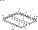
FIG. 8 is a bottom perspective view of the first panel support device of the heat keeping apparatus according to an embodiment of the present disclosure. -
FIG. 9 is a cross-sectional view of a second panel support device of the heat keeping apparatus according to an embodiment of the present disclosure. - Hereinafter, embodiments of the present disclosure will be described in detail with reference to the accompanying drawings. The following embodiments are provided to fully convey the spirit of the present disclosure to a person having ordinary skill in the art to which the present disclosure belongs. The present disclosure is not limited to the embodiments shown herein but may be embodied in other forms. The drawings are not intended to limit the scope of the present disclosure in any way, and the size of components may be exaggerated for clarity of illustration.
-
FIG. 1 is a perspective view showing rolling equipment to which a heat keeping apparatus according to an embodiment of the present disclosure is applied. Referring toFIG. 1 , a rolling equipment includes aheating furnace 10 to heat a material for rolling, a roughingmill 30 to roll amaterial 20 heated in theheating furnace 10, a finishingmill 40 to roll thematerial 20 rough-rolled, and a transfer line 50 (roller table) to transfer thematerial 20 from theheating furnace 10 to the roughingmill 30 and transfer thematerial 20 from the roughingmill 30 to the finishingmill 40. - A
heat keeping apparatus 100 may be installed on thetransfer line 50 between the roughingmill 30 and the finishingmill 40. The heat keepingapparatus 100 covers the outside of thematerial 20 to be transferred to thefinishing mill 40 through the roughingmill 30 to prevent an excessive drop in a temperature of thematerial 20 during a transfer process. This is to reduce the temperature drop of thematerial 20 entering thefinishing mill 40 so that a rear end of thematerial 20 may be rolled satisfactorily in thefinishing mill 40. - The present embodiment illustrates that the
heat keeping apparatus 100 is installed on thetransfer line 50 between the roughingmill 30 and thefinishing mill 40, but an installation location of theheat keeping apparatus 100 is not limited thereto. The heat keepingapparatus 100 may be installed at another location of the rolling equipment to prevent temperature drop of thematerial 20. -
FIG. 2 is an exploded perspective view of a heat keeping cover of the heat keeping apparatus, andFIGS. 3 and4 are front views of the heat keeping apparatus, showing states in which first and second side cover parts are unfolded and folded, respectively.FIG. 5 is a cross-sectional view of a heat keeping cover. - Referring to
FIGS. 2 to 4 , theheat keeping apparatus 100 may include aheat keeping cover 101 installed above thetransfer line 50 to cover the outside of thematerial 20 being transferred along thetransfer line 50 to keep heat of thematerial 20, and an opening/closing device 102 capable of raising and lowering theheat keeping cover 101 and opening theheat keeping cover 101 when necessary. - The
heat keeping cover 101 includes anupper cover part 110 to cover an upper portion of thematerial 20, a firstside cover part 120 and a secondside cover part 130 rotatably connected to both sides of theupper cover part 110, respectively, to cover both sides of thematerial 20, a first actuactingpart 140 to adjust an unfolding of the firstside cover part 120 by rotating the firstside cover part 120, and a second actuactingpart 150 to adjust an unfolding of the secondside cover part 130 by rotating the secondside cover part 130. - Referring to
FIG. 3 , theupper cover part 110 and the first and secondside cover parts heat keeping cover 101 may form a tunnel having an arc-shaped cross-sectional structure by combining theupper cover part 110, the firstside cover part 120, and the secondside cover part 130 with each other. The tunnel-typeheat keeping cover 101 may enhance a heat keeping effect of thematerial 20 by reflecting the radiant energy radiated from the material 20 toward the material 20 again. - The first
side cover part 120 and the secondside cover part 130 may be rotated to unfold to the both sides when the material 20 having a wide width is transferred as shown inFIG. 3 to widen a heat keeping area, and may be rotated to fold inward when amaterial 20a having a narrow width is transferred as shown inFIG. 4 to narrow the heat keeping area. That is, the heat keeping effect of thematerials heat keeping cover 101 to correspond to the size of thematerials parts upper cover part 110 may be raised, and when the first and second side coverparts upper cover part 110 may be lowered. - The first and second
actuacting parts upper cover part 110 and the other side thereof connected to the first or secondside cover part side cover part - The present embodiment illustrates the
first actuacting part 140 and thesecond actuacting part 150 to adjust an angle by actuacting the firstside cover part 120 and the secondside cover part 130, respectively, but the firstside cover part 120 and the secondside cover part 130 may be operated simultaneously by one actuacting part. For example, by transmitting power from one actuacting part installed above theupper cover part 110 to the first and second side coverparts parts - Referring to
FIGS. 2 ,3 , and5 , theupper cover part 110 may include anupper frame 111 formed in an arc shape, a firstpanel support device 160 and a secondpanel support device 170 bufferably mounted below theupper frame 111, and a first upperreflective panel 181 and a second upperreflective panel 182 supported by the first and secondpanel support devices - The first
side cover part 120 and the secondside cover part 130 may include side frames 121 and 131 of an arc shape connected to ends of theupper frame 111, and sidereflective panels 183 coupled to lower sides of the side frames 121 and 131, respectively. - As shown in
FIG. 2 , a plurality of theupper frames 111 may be disposed to be spaced apart from each other in a transferring direction of thematerial 20 and may be interconnected by a plurality of connection frames 112 extending in a direction of crossing the upper frames 111. Like theupper frame 111, a plurality of the side frames 121 and 131 may also be interconnected by a plurality of connection frames 122 in a state of being disposed to be spaced apart from each other in the transferring direction of thematerial 20. One end of the side frames 121 and 131 of the first and second side coverparts upper frame 111. - As shown in
FIG. 5 , the firstpanel support device 160 and the secondpanel support device 170 are sequentially installed below theupper frame 111 in a lateral direction from the center thereof. Also, the first and secondpanel support devices heat keeping cover 101 in the same manner.FIG. 5 shows only one side of theheat keeping cover 101, but the first and secondpanel support devices heat keeping cover 101. - Referring to
FIGS. 6 to 8 , the firstpanel support device 160 may include arectangular panel frame 161 accommodating the first upperreflective panel 181 and having open upper and lower sides, a plurality ofcoupling members 162 installed on thepanel frame 161 to support a circumference of the first upperreflective panel 181 and allow thermal deformation of the first upperreflective panel 181 by elastic deformation, and a plurality ofbuffer connection members 163 to bufferably connect thepanel frame 161 to theupper frame 111. - The first upper
reflective panel 181 may have a rectangular panel shape smaller than thepanel frame 161 to be accommodated in thepanel frame 161. The first upperreflective panel 181 may be made of a material such as aluminum, aluminum alloy, zinc oxide, stainless steel that may reflect most of the radiant energy because an emissivity of radiant energy is very low. - As shown in
FIGS. 7 and8 , thepanel frame 161 includes one ormore side slots 164 formed in a size through which the first upperreflective panel 181 may pass. The present embodiment illustrates that theside slot 164 is formed on each of four sides of thepanel frame 161. Theside slots 164 allow the first upperreflective panel 181 to be mounted from the sides of thepanel frame 161 and may prevent the first upperreflective panel 181 from being bent by receiving deformation generated when the first upperreflective panel 181 is stretched in a width direction due to thermal deformation. - As shown in
FIG. 6 , the plurality ofcoupling members 162 may be installed in a state of being spaced apart from each other on thepanel frame 161 to support the circumference of the first upperreflective panel 181. Each of thecoupling members 162 may be provided by bending a leaf spring. Each of thecoupling members 162 may include acoupling groove 162a detachably coupled to the circumference of the first upperreflective panel 181, and anelastic deformation part 162b extending from thecoupling groove 162a in a bent state and fixed to thepanel frame 161 to allow deformation of the first upperreflective panel 181 in the width direction. The circumference of the first upperreflective panel 181 may be maintained in a state of being spaced apart from thepanel frame 161 by being supported by the plurality ofcoupling members 162. - As shown in
FIGS. 6 and7 , each of the plurality ofbuffer connection members 163 may be a coil spring having one side connected to an upper edge of thepanel frame 161 and the other side connected to theupper frame 111. The present embodiment illustrates a coil spring, but the plurality ofbuffer connection members 163 may be plate springs capable of elastic deformation. - Referring to
FIGS. 6 and8 , the firstpanel support device 160 may include acollision bumper 165 installed below thepanel frame 161 to protect the first upperreflective panel 181 from collision of thematerial 20. Thecollision bumper 165 may be provided to protrude downward of thepanel frame 161, extend long in the transferring direction of thematerial 20, and have both ends fixed to a lower end of thepanel frame 161. - Referring to
FIGS. 7 and8 , thepanel frame 161 may include reinforcingparts panel frame 161 to each other. The reinforcingparts panel frame 161 by crossing and connecting the upper or lower sides of thepanel frame 161 in the direction in which thematerial 20 is transferred. - Referring to
FIGS. 5 and9 , the secondpanel support device 170 may also be provided similarly to the firstpanel support device 160. The secondpanel support device 170 may also include arectangular panel frame 171 to accommodate and support the second upperreflective panel 182, a plurality ofcoupling members 172, a plurality ofbuffer connection members 173, and acollision bumper 175. However, the secondpanel support device 170 may be provided such that a thickness of thepanel frame 171 gradually decreases in a lateral direction so that the secondpanel support device 170 may be mounted corresponding to a curvature of the arc-shapedupper frame 111. The second upperreflective panel 182 may also be made of the same material as the first upperreflective panel 181 and installed on thepanel frame 171 in a similar manner to the first upperreflective panel 181. - Referring to
FIGS. 2 and5 , the sidereflective panels 183 installed on the first and second side coverparts parts material 20, the sidereflective panels 183 may be directly fixed to the side frames 121 and 131 by fastening screws or the like. - The side
reflective panels 183 may also be made of the same material as the first and second upperreflective panels reflective panels 183 are coupled by fastening fixing screws. - The
heat keeping cover 101 as above may quickly reflect most of the radiant energy radiated from the material toward the material because the plurality of first and second upperreflective panels reflective panels 183 are made of a material having a low emissivity and a high reflectance. In addition, because theheat keeping cover 101 has an arc-shaped cross-sectional structure so that the reflected energy may be concentrated on the material, the heat keeping effect of the material 20 may be enhanced compared to a conventional one. - In the
heat keeping apparatus 100 of the present embodiment, because the form of theheat keeping cover 101 may be changed in a manner in which the firstside cover part 120 and the secondside cover part 130 are folded or unfolded depending on the size of the material 20 to be transferred, the heat keeping effect of the material 20 may be enhanced. - In the
heat keeping apparatus 100 of the present embodiment, because even when the material 20 being transferred collides with a lower surface of theheat keeping cover 101, thecollision bumpers reflective panels buffer connection members heat keeping cover 101 may be prevented. - In the
heat keeping apparatus 100 of the present embodiment, because the first and second upperreflective panels deformable coupling members side slots reflective panels reflective panels reflective panels - In the
heat keeping apparatus 100 of the present embodiment, because the first or second upperreflective panel side slots coupling members reflective panels
Claims (12)
- A heat keeping apparatus for a rolling transfer line comprising:a heat keeping cover configured to cover and heat the outside of a material being transferred along the transfer line,wherein the heat keeping cover comprises:an upper cover part provided to cover an upper side of the material;first and second side cover parts provided to cover sides of the material and rotatably connected to both sides of the upper cover part; andat least one actuacting part provided to adjust unfolding of the first or second side cover part by rotating the first or second side cover part.
- The heat keeping apparatus according to claim 1, wherein
the upper cover part comprises an upper frame, a panel support device bufferably mounted on the upper frame, and an upper reflective panel supported by the panel support device to be replaceable and thermally deformable, and
each of the first and second side cover parts comprises a side frame rotatably connected to the upper frame, and a side reflective panel supported by the side frame. - The heat keeping apparatus according to claim 1 or 2, wherein
the heat keeping cover is provided such that cross-sectional structures of the upper cover part and the first and second side cover parts have an arc shape. - The heat keeping apparatus according to claim 2, wherein
the panel support device comprises:a rectangular panel frame provided to accommodate the upper reflective panel and having open upper and lower sides;a plurality of coupling members installed on the panel frame to support a circumference of the upper reflective panel and allow thermal deformation of the upper reflective panel by elastic deformation; anda plurality of buffer connection members provided to bufferably connect the panel frame to the upper frame. - The heat keeping apparatus according to claim 4, wherein
the panel support device further comprises a collision bumper installed below the panel frame to protect the upper reflective panel from collision of the material. - The heat keeping apparatus according to claim 5, wherein
the collision bumper is provided to protrude downward of the panel frame, extend in a transferring direction of the material, and have both ends fixed to the panel frame. - The heat keeping apparatus according to claim 4, wherein
the panel frame comprises one or more side slots formed in a size that allows the upper reflective panel to pass through for mounting and thermal deformation of the upper reflective panel. - The heat keeping apparatus according to claim 4, wherein
each of the plurality of coupling members comprises a coupling groove detachably coupled to a circumference of the upper reflective panel, and an elastic deformation part extending from the coupling groove in a bent state and fixed to the panel frame to allow deformation of the upper reflective panel in a width direction. - The heat keeping apparatus according to claim 4, wherein
each of the plurality of buffer connection members comprises a coil spring having one side connected to an edge of the panel frame and the other side connected to the upper frame. - The heat keeping apparatus according to claim 4, wherein
the panel frame comprises a reinforcing part provided to cross and connect upper sides or lower sides of the panel frame. - The heat keeping apparatus according to claim 2, wherein
the upper frame and the side frame are bent in an arc shape, and
the side reflective panel is fixed to the side frame in a state in which a reflection surface is bent to form an inner curved surface. - The heat keeping apparatus according to claim 1, wherein
the at least one actuacting part comprises a first actuacting part to rotate the first side cover part and a second actuacting part to rotate the second side cover part.
Applications Claiming Priority (2)
| Application Number | Priority Date | Filing Date | Title |
|---|---|---|---|
| KR1020180133166A KR102157869B1 (en) | 2018-11-01 | 2018-11-01 | Heat keeping device for rolling conveying line |
| PCT/KR2019/008786 WO2020091189A1 (en) | 2018-11-01 | 2019-07-16 | Heat-retaining rolling equipment |
Publications (3)
| Publication Number | Publication Date |
|---|---|
| EP3858504A1 true EP3858504A1 (en) | 2021-08-04 |
| EP3858504A4 EP3858504A4 (en) | 2021-11-03 |
| EP3858504B1 EP3858504B1 (en) | 2023-06-07 |
Family
ID=70462486
Family Applications (1)
| Application Number | Title | Priority Date | Filing Date |
|---|---|---|---|
| EP19877729.4A Active EP3858504B1 (en) | 2018-11-01 | 2019-07-16 | Heat-retaining rolling equipment |
Country Status (6)
| Country | Link |
|---|---|
| EP (1) | EP3858504B1 (en) |
| KR (1) | KR102157869B1 (en) |
| CN (1) | CN112996609B (en) |
| AU (1) | AU2019371023B2 (en) |
| ES (1) | ES2953732T3 (en) |
| WO (1) | WO2020091189A1 (en) |
Family Cites Families (15)
| Publication number | Priority date | Publication date | Assignee | Title |
|---|---|---|---|---|
| JPS5713330Y2 (en) * | 1978-05-19 | 1982-03-17 | ||
| EP0042656B1 (en) * | 1978-11-07 | 1984-08-08 | Encomech Engineering Services Limited | Heat shield arrangements |
| BE893565A (en) * | 1982-06-18 | 1982-10-18 | Cockerill Sambre Sa | Thermal tunnel for rolling mill conveyors - with high insulating efficiency and automatic lifting |
| DE3508060C1 (en) * | 1985-03-07 | 1986-02-27 | Mannesmann AG, 4000 Düsseldorf | Heat hoods for hot-strip mill trains |
| FR2607036B1 (en) * | 1986-11-24 | 1992-07-03 | Usinor Aciers | REMOVABLE TUNNEL FOR HOLDING A HOT-ROLLED TEMPERATURE IN A CONTINUOUS LAMINATION TRAIN |
| JPH0289515A (en) * | 1988-09-26 | 1990-03-29 | Sumitomo Metal Ind Ltd | Heat insulating cover for high temperature steel material |
| KR910006321Y1 (en) * | 1989-11-15 | 1991-08-22 | 포항종합제철 주식회사 | Windproof device for strips installed on a delay table |
| EP0968774B1 (en) * | 1997-11-26 | 2006-02-08 | Ishikawajima-Harima Heavy Industries Co., Ltd. | A method for manufacturing a hot-rolled steel strip |
| KR200301639Y1 (en) * | 1998-12-23 | 2003-04-08 | 주식회사 포스코 | Deformation prevention structure of heat insulation heat insulation board |
| JP3358576B2 (en) * | 1999-02-03 | 2002-12-24 | 住友金属工業株式会社 | Heat insulation material for heated material |
| KR100775487B1 (en) * | 2001-12-05 | 2007-11-12 | 주식회사 포스코 | Rolled air preservation and preheating device |
| IT1400003B1 (en) * | 2010-05-18 | 2013-05-09 | Danieli Off Mecc | CONTINUOUS CASTING DEVICE AND ITS PROCEDURE |
| KR200462426Y1 (en) * | 2010-12-09 | 2012-09-10 | 현대하이스코 주식회사 | Equipment of the dew condensation barrier mambrabe |
| KR101424429B1 (en) * | 2012-10-29 | 2014-08-01 | 현대제철 주식회사 | Transferring apparatus for fuel and raw material |
| KR101568612B1 (en) * | 2014-09-26 | 2015-11-12 | 주식회사 포스코 | Apparatus for slowly cooling wire rod coil |
-
2018
- 2018-11-01 KR KR1020180133166A patent/KR102157869B1/en active Active
-
2019
- 2019-07-16 EP EP19877729.4A patent/EP3858504B1/en active Active
- 2019-07-16 CN CN201980072418.4A patent/CN112996609B/en active Active
- 2019-07-16 AU AU2019371023A patent/AU2019371023B2/en active Active
- 2019-07-16 ES ES19877729T patent/ES2953732T3/en active Active
- 2019-07-16 WO PCT/KR2019/008786 patent/WO2020091189A1/en not_active Ceased
Also Published As
| Publication number | Publication date |
|---|---|
| CN112996609A (en) | 2021-06-18 |
| AU2019371023A1 (en) | 2021-06-03 |
| EP3858504B1 (en) | 2023-06-07 |
| KR102157869B1 (en) | 2020-09-21 |
| WO2020091189A1 (en) | 2020-05-07 |
| KR20200050293A (en) | 2020-05-11 |
| ES2953732T3 (en) | 2023-11-15 |
| AU2019371023B2 (en) | 2022-10-13 |
| EP3858504A4 (en) | 2021-11-03 |
| CN112996609B (en) | 2023-11-24 |
Similar Documents
| Publication | Publication Date | Title |
|---|---|---|
| EP0049000A2 (en) | Heat shields for rolling mills | |
| US8789392B2 (en) | Apparatus for shaping glass and methods | |
| US4237956A (en) | Solar heated door | |
| JPH0411281B2 (en) | ||
| US2736140A (en) | black | |
| AU2019371023B2 (en) | Heat-retaining rolling equipment | |
| EP0677337B1 (en) | Heat shields for roller tables | |
| ES2248740T3 (en) | COIL BOX, WHICH IS PROVIDED BETWEEN PRIOR AND FINISHED LAMINATION TRAINS. | |
| EP0042656B1 (en) | Heat shield arrangements | |
| KR102249972B1 (en) | Heat reflective panel assembly and equipment for maintaining heat of rolling line including the same | |
| WO2013028522A2 (en) | Control and tracking system and method for a solar power generation system | |
| JP5416704B2 (en) | Solar energy collector | |
| CN221225563U (en) | Double-cabinet-door unmanned sales counter with demisting function | |
| CA2465290A1 (en) | Furnace doors for coiler furnaces | |
| JP2013199754A (en) | Frame for light reception panel | |
| KR200192851Y1 (en) | Work roll heating device for temper rolling | |
| GB2295657A (en) | Soot blower unit | |
| CA2024659C (en) | Method of reducing windshield residual stresses | |
| US5960663A (en) | Method and means of temperature control | |
| CN222695635U (en) | A strip steel insulation device and hot rolling production line | |
| CN218085067U (en) | Automobile radiator baffle with good protection effect | |
| AU725900B2 (en) | Method and apparatus for controlling bending of a glass in a glass bending oven | |
| ES2223361T3 (en) | KITCHEN OVEN WITH GLASS WINDOW FOR OVEN DOOR. | |
| JP2646873B2 (en) | blind | |
| KR20190046075A (en) | Heat keeping apparatus for hot rolling mill transfer line |
Legal Events
| Date | Code | Title | Description |
|---|---|---|---|
| STAA | Information on the status of an ep patent application or granted ep patent |
Free format text: STATUS: THE INTERNATIONAL PUBLICATION HAS BEEN MADE |
|
| PUAI | Public reference made under article 153(3) epc to a published international application that has entered the european phase |
Free format text: ORIGINAL CODE: 0009012 |
|
| STAA | Information on the status of an ep patent application or granted ep patent |
Free format text: STATUS: REQUEST FOR EXAMINATION WAS MADE |
|
| 17P | Request for examination filed |
Effective date: 20210427 |
|
| AK | Designated contracting states |
Kind code of ref document: A1 Designated state(s): AL AT BE BG CH CY CZ DE DK EE ES FI FR GB GR HR HU IE IS IT LI LT LU LV MC MK MT NL NO PL PT RO RS SE SI SK SM TR |
|
| A4 | Supplementary search report drawn up and despatched |
Effective date: 20211001 |
|
| RIC1 | Information provided on ipc code assigned before grant |
Ipc: B21B 45/00 20060101AFI20210927BHEP |
|
| DAV | Request for validation of the european patent (deleted) | ||
| DAX | Request for extension of the european patent (deleted) | ||
| RAP3 | Party data changed (applicant data changed or rights of an application transferred) |
Owner name: POSCO HOLDINGS INC. |
|
| GRAP | Despatch of communication of intention to grant a patent |
Free format text: ORIGINAL CODE: EPIDOSNIGR1 |
|
| STAA | Information on the status of an ep patent application or granted ep patent |
Free format text: STATUS: GRANT OF PATENT IS INTENDED |
|
| INTG | Intention to grant announced |
Effective date: 20221222 |
|
| RAP1 | Party data changed (applicant data changed or rights of an application transferred) |
Owner name: POSCO CO., LTD |
|
| GRAS | Grant fee paid |
Free format text: ORIGINAL CODE: EPIDOSNIGR3 |
|
| GRAA | (expected) grant |
Free format text: ORIGINAL CODE: 0009210 |
|
| STAA | Information on the status of an ep patent application or granted ep patent |
Free format text: STATUS: THE PATENT HAS BEEN GRANTED |
|
| AK | Designated contracting states |
Kind code of ref document: B1 Designated state(s): AL AT BE BG CH CY CZ DE DK EE ES FI FR GB GR HR HU IE IS IT LI LT LU LV MC MK MT NL NO PL PT RO RS SE SI SK SM TR |
|
| REG | Reference to a national code |
Ref country code: GB Ref legal event code: FG4D |
|
| REG | Reference to a national code |
Ref country code: CH Ref legal event code: EP Ref country code: AT Ref legal event code: REF Ref document number: 1573436 Country of ref document: AT Kind code of ref document: T Effective date: 20230615 |
|
| REG | Reference to a national code |
Ref country code: DE Ref legal event code: R096 Ref document number: 602019030786 Country of ref document: DE |
|
| REG | Reference to a national code |
Ref country code: LT Ref legal event code: MG9D |
|
| REG | Reference to a national code |
Ref country code: NL Ref legal event code: MP Effective date: 20230607 |
|
| PG25 | Lapsed in a contracting state [announced via postgrant information from national office to epo] |
Ref country code: SE Free format text: LAPSE BECAUSE OF FAILURE TO SUBMIT A TRANSLATION OF THE DESCRIPTION OR TO PAY THE FEE WITHIN THE PRESCRIBED TIME-LIMIT Effective date: 20230607 Ref country code: NO Free format text: LAPSE BECAUSE OF FAILURE TO SUBMIT A TRANSLATION OF THE DESCRIPTION OR TO PAY THE FEE WITHIN THE PRESCRIBED TIME-LIMIT Effective date: 20230907 |
|
| PGFP | Annual fee paid to national office [announced via postgrant information from national office to epo] |
Ref country code: IT Payment date: 20230920 Year of fee payment: 5 Ref country code: ES Payment date: 20230828 Year of fee payment: 5 |
|
| REG | Reference to a national code |
Ref country code: AT Ref legal event code: MK05 Ref document number: 1573436 Country of ref document: AT Kind code of ref document: T Effective date: 20230607 Ref country code: ES Ref legal event code: FG2A Ref document number: 2953732 Country of ref document: ES Kind code of ref document: T3 Effective date: 20231115 |
|
| PG25 | Lapsed in a contracting state [announced via postgrant information from national office to epo] |
Ref country code: RS Free format text: LAPSE BECAUSE OF FAILURE TO SUBMIT A TRANSLATION OF THE DESCRIPTION OR TO PAY THE FEE WITHIN THE PRESCRIBED TIME-LIMIT Effective date: 20230607 Ref country code: NL Free format text: LAPSE BECAUSE OF FAILURE TO SUBMIT A TRANSLATION OF THE DESCRIPTION OR TO PAY THE FEE WITHIN THE PRESCRIBED TIME-LIMIT Effective date: 20230607 Ref country code: LV Free format text: LAPSE BECAUSE OF FAILURE TO SUBMIT A TRANSLATION OF THE DESCRIPTION OR TO PAY THE FEE WITHIN THE PRESCRIBED TIME-LIMIT Effective date: 20230607 Ref country code: LT Free format text: LAPSE BECAUSE OF FAILURE TO SUBMIT A TRANSLATION OF THE DESCRIPTION OR TO PAY THE FEE WITHIN THE PRESCRIBED TIME-LIMIT Effective date: 20230607 Ref country code: HR Free format text: LAPSE BECAUSE OF FAILURE TO SUBMIT A TRANSLATION OF THE DESCRIPTION OR TO PAY THE FEE WITHIN THE PRESCRIBED TIME-LIMIT Effective date: 20230607 Ref country code: GR Free format text: LAPSE BECAUSE OF FAILURE TO SUBMIT A TRANSLATION OF THE DESCRIPTION OR TO PAY THE FEE WITHIN THE PRESCRIBED TIME-LIMIT Effective date: 20230908 |
|
| PGFP | Annual fee paid to national office [announced via postgrant information from national office to epo] |
Ref country code: DE Payment date: 20230725 Year of fee payment: 5 |
|
| PG25 | Lapsed in a contracting state [announced via postgrant information from national office to epo] |
Ref country code: FI Free format text: LAPSE BECAUSE OF FAILURE TO SUBMIT A TRANSLATION OF THE DESCRIPTION OR TO PAY THE FEE WITHIN THE PRESCRIBED TIME-LIMIT Effective date: 20230607 |
|
| PG25 | Lapsed in a contracting state [announced via postgrant information from national office to epo] |
Ref country code: SK Free format text: LAPSE BECAUSE OF FAILURE TO SUBMIT A TRANSLATION OF THE DESCRIPTION OR TO PAY THE FEE WITHIN THE PRESCRIBED TIME-LIMIT Effective date: 20230607 |
|
| PG25 | Lapsed in a contracting state [announced via postgrant information from national office to epo] |
Ref country code: IS Free format text: LAPSE BECAUSE OF FAILURE TO SUBMIT A TRANSLATION OF THE DESCRIPTION OR TO PAY THE FEE WITHIN THE PRESCRIBED TIME-LIMIT Effective date: 20231007 |
|
| PG25 | Lapsed in a contracting state [announced via postgrant information from national office to epo] |
Ref country code: SM Free format text: LAPSE BECAUSE OF FAILURE TO SUBMIT A TRANSLATION OF THE DESCRIPTION OR TO PAY THE FEE WITHIN THE PRESCRIBED TIME-LIMIT Effective date: 20230607 Ref country code: SK Free format text: LAPSE BECAUSE OF FAILURE TO SUBMIT A TRANSLATION OF THE DESCRIPTION OR TO PAY THE FEE WITHIN THE PRESCRIBED TIME-LIMIT Effective date: 20230607 Ref country code: RO Free format text: LAPSE BECAUSE OF FAILURE TO SUBMIT A TRANSLATION OF THE DESCRIPTION OR TO PAY THE FEE WITHIN THE PRESCRIBED TIME-LIMIT Effective date: 20230607 Ref country code: PT Free format text: LAPSE BECAUSE OF FAILURE TO SUBMIT A TRANSLATION OF THE DESCRIPTION OR TO PAY THE FEE WITHIN THE PRESCRIBED TIME-LIMIT Effective date: 20231009 Ref country code: IS Free format text: LAPSE BECAUSE OF FAILURE TO SUBMIT A TRANSLATION OF THE DESCRIPTION OR TO PAY THE FEE WITHIN THE PRESCRIBED TIME-LIMIT Effective date: 20231007 Ref country code: EE Free format text: LAPSE BECAUSE OF FAILURE TO SUBMIT A TRANSLATION OF THE DESCRIPTION OR TO PAY THE FEE WITHIN THE PRESCRIBED TIME-LIMIT Effective date: 20230607 Ref country code: CZ Free format text: LAPSE BECAUSE OF FAILURE TO SUBMIT A TRANSLATION OF THE DESCRIPTION OR TO PAY THE FEE WITHIN THE PRESCRIBED TIME-LIMIT Effective date: 20230607 Ref country code: AT Free format text: LAPSE BECAUSE OF FAILURE TO SUBMIT A TRANSLATION OF THE DESCRIPTION OR TO PAY THE FEE WITHIN THE PRESCRIBED TIME-LIMIT Effective date: 20230607 |
|
| PG25 | Lapsed in a contracting state [announced via postgrant information from national office to epo] |
Ref country code: PL Free format text: LAPSE BECAUSE OF FAILURE TO SUBMIT A TRANSLATION OF THE DESCRIPTION OR TO PAY THE FEE WITHIN THE PRESCRIBED TIME-LIMIT Effective date: 20230607 |
|
| REG | Reference to a national code |
Ref country code: CH Ref legal event code: PL |
|
| REG | Reference to a national code |
Ref country code: DE Ref legal event code: R097 Ref document number: 602019030786 Country of ref document: DE |
|
| PG25 | Lapsed in a contracting state [announced via postgrant information from national office to epo] |
Ref country code: MC Free format text: LAPSE BECAUSE OF FAILURE TO SUBMIT A TRANSLATION OF THE DESCRIPTION OR TO PAY THE FEE WITHIN THE PRESCRIBED TIME-LIMIT Effective date: 20230607 |
|
| REG | Reference to a national code |
Ref country code: BE Ref legal event code: MM Effective date: 20230731 |
|
| PG25 | Lapsed in a contracting state [announced via postgrant information from national office to epo] |
Ref country code: LU Free format text: LAPSE BECAUSE OF NON-PAYMENT OF DUE FEES Effective date: 20230716 |
|
| PG25 | Lapsed in a contracting state [announced via postgrant information from national office to epo] |
Ref country code: MC Free format text: LAPSE BECAUSE OF FAILURE TO SUBMIT A TRANSLATION OF THE DESCRIPTION OR TO PAY THE FEE WITHIN THE PRESCRIBED TIME-LIMIT Effective date: 20230607 Ref country code: LU Free format text: LAPSE BECAUSE OF NON-PAYMENT OF DUE FEES Effective date: 20230716 |
|
| PLBE | No opposition filed within time limit |
Free format text: ORIGINAL CODE: 0009261 |
|
| STAA | Information on the status of an ep patent application or granted ep patent |
Free format text: STATUS: NO OPPOSITION FILED WITHIN TIME LIMIT |
|
| REG | Reference to a national code |
Ref country code: IE Ref legal event code: MM4A |
|
| PG25 | Lapsed in a contracting state [announced via postgrant information from national office to epo] |
Ref country code: DK Free format text: LAPSE BECAUSE OF FAILURE TO SUBMIT A TRANSLATION OF THE DESCRIPTION OR TO PAY THE FEE WITHIN THE PRESCRIBED TIME-LIMIT Effective date: 20230607 Ref country code: CH Free format text: LAPSE BECAUSE OF NON-PAYMENT OF DUE FEES Effective date: 20230731 |
|
| PG25 | Lapsed in a contracting state [announced via postgrant information from national office to epo] |
Ref country code: SI Free format text: LAPSE BECAUSE OF FAILURE TO SUBMIT A TRANSLATION OF THE DESCRIPTION OR TO PAY THE FEE WITHIN THE PRESCRIBED TIME-LIMIT Effective date: 20230607 |
|
| 26N | No opposition filed |
Effective date: 20240308 |
|
| GBPC | Gb: european patent ceased through non-payment of renewal fee |
Effective date: 20230907 |
|
| PG25 | Lapsed in a contracting state [announced via postgrant information from national office to epo] |
Ref country code: SI Free format text: LAPSE BECAUSE OF FAILURE TO SUBMIT A TRANSLATION OF THE DESCRIPTION OR TO PAY THE FEE WITHIN THE PRESCRIBED TIME-LIMIT Effective date: 20230607 Ref country code: BE Free format text: LAPSE BECAUSE OF NON-PAYMENT OF DUE FEES Effective date: 20230731 |
|
| PG25 | Lapsed in a contracting state [announced via postgrant information from national office to epo] |
Ref country code: IE Free format text: LAPSE BECAUSE OF NON-PAYMENT OF DUE FEES Effective date: 20230716 |
|
| PG25 | Lapsed in a contracting state [announced via postgrant information from national office to epo] |
Ref country code: GB Free format text: LAPSE BECAUSE OF NON-PAYMENT OF DUE FEES Effective date: 20230907 |
|
| PG25 | Lapsed in a contracting state [announced via postgrant information from national office to epo] |
Ref country code: IE Free format text: LAPSE BECAUSE OF NON-PAYMENT OF DUE FEES Effective date: 20230716 Ref country code: GB Free format text: LAPSE BECAUSE OF NON-PAYMENT OF DUE FEES Effective date: 20230907 Ref country code: FR Free format text: LAPSE BECAUSE OF NON-PAYMENT OF DUE FEES Effective date: 20230807 |
|
| PG25 | Lapsed in a contracting state [announced via postgrant information from national office to epo] |
Ref country code: BG Free format text: LAPSE BECAUSE OF FAILURE TO SUBMIT A TRANSLATION OF THE DESCRIPTION OR TO PAY THE FEE WITHIN THE PRESCRIBED TIME-LIMIT Effective date: 20230607 |
|
| PG25 | Lapsed in a contracting state [announced via postgrant information from national office to epo] |
Ref country code: BG Free format text: LAPSE BECAUSE OF FAILURE TO SUBMIT A TRANSLATION OF THE DESCRIPTION OR TO PAY THE FEE WITHIN THE PRESCRIBED TIME-LIMIT Effective date: 20230607 |
|
| REG | Reference to a national code |
Ref country code: DE Ref legal event code: R119 Ref document number: 602019030786 Country of ref document: DE |
|
| PG25 | Lapsed in a contracting state [announced via postgrant information from national office to epo] |
Ref country code: DE Free format text: LAPSE BECAUSE OF NON-PAYMENT OF DUE FEES Effective date: 20250201 |
|
| PG25 | Lapsed in a contracting state [announced via postgrant information from national office to epo] |
Ref country code: IT Free format text: LAPSE BECAUSE OF NON-PAYMENT OF DUE FEES Effective date: 20240716 |
|
| PG25 | Lapsed in a contracting state [announced via postgrant information from national office to epo] |
Ref country code: CY Free format text: LAPSE BECAUSE OF FAILURE TO SUBMIT A TRANSLATION OF THE DESCRIPTION OR TO PAY THE FEE WITHIN THE PRESCRIBED TIME-LIMIT; INVALID AB INITIO Effective date: 20190716 |
|
| PG25 | Lapsed in a contracting state [announced via postgrant information from national office to epo] |
Ref country code: HU Free format text: LAPSE BECAUSE OF FAILURE TO SUBMIT A TRANSLATION OF THE DESCRIPTION OR TO PAY THE FEE WITHIN THE PRESCRIBED TIME-LIMIT; INVALID AB INITIO Effective date: 20190716 |
|
| REG | Reference to a national code |
Ref country code: ES Ref legal event code: FD2A Effective date: 20250828 |
|
| PG25 | Lapsed in a contracting state [announced via postgrant information from national office to epo] |
Ref country code: ES Free format text: LAPSE BECAUSE OF NON-PAYMENT OF DUE FEES Effective date: 20240717 |
|
| PG25 | Lapsed in a contracting state [announced via postgrant information from national office to epo] |
Ref country code: TR Free format text: LAPSE BECAUSE OF FAILURE TO SUBMIT A TRANSLATION OF THE DESCRIPTION OR TO PAY THE FEE WITHIN THE PRESCRIBED TIME-LIMIT Effective date: 20230607 |