EP3858431A1 - Charging and updating of an implantable hearing aid - Google Patents
Charging and updating of an implantable hearing aid Download PDFInfo
- Publication number
- EP3858431A1 EP3858431A1 EP21152525.8A EP21152525A EP3858431A1 EP 3858431 A1 EP3858431 A1 EP 3858431A1 EP 21152525 A EP21152525 A EP 21152525A EP 3858431 A1 EP3858431 A1 EP 3858431A1
- Authority
- EP
- European Patent Office
- Prior art keywords
- hearing aid
- implantable
- inductive
- resonance frequency
- aid system
- Prior art date
- Legal status (The legal status is an assumption and is not a legal conclusion. Google has not performed a legal analysis and makes no representation as to the accuracy of the status listed.)
- Granted
Links
Images




Classifications
-
- H—ELECTRICITY
- H02—GENERATION; CONVERSION OR DISTRIBUTION OF ELECTRIC POWER
- H02J—ELECTRIC POWER NETWORKS; CIRCUIT ARRANGEMENTS OR SYSTEMS FOR SUPPLYING OR DISTRIBUTING ELECTRIC POWER; SYSTEMS FOR STORING ELECTRIC ENERGY
- H02J50/00—Circuit arrangements or systems for wireless supply or distribution of electric power
- H02J50/10—Circuit arrangements or systems for wireless supply or distribution of electric power using inductive coupling
- H02J50/12—Circuit arrangements or systems for wireless supply or distribution of electric power using inductive coupling of the resonant type
-
- H—ELECTRICITY
- H04—ELECTRIC COMMUNICATION TECHNIQUE
- H04R—LOUDSPEAKERS, MICROPHONES, GRAMOPHONE PICK-UPS OR LIKE ACOUSTIC ELECTROMECHANICAL TRANSDUCERS; ELECTRIC HEARING AIDS; PUBLIC ADDRESS SYSTEMS
- H04R25/00—Electric hearing aids
- H04R25/30—Monitoring or testing of hearing aids, e.g. functioning, settings, battery power
-
- A—HUMAN NECESSITIES
- A61—MEDICAL OR VETERINARY SCIENCE; HYGIENE
- A61N—ELECTROTHERAPY; MAGNETOTHERAPY; RADIATION THERAPY; ULTRASOUND THERAPY
- A61N1/00—Electrotherapy; Circuits therefor
- A61N1/18—Applying electric currents by contact electrodes
- A61N1/32—Applying electric currents by contact electrodes alternating or intermittent currents
- A61N1/36—Applying electric currents by contact electrodes alternating or intermittent currents for stimulation
- A61N1/372—Arrangements in connection with the implantation of stimulators
- A61N1/378—Electrical supply
- A61N1/3787—Electrical supply from an external energy source
-
- H—ELECTRICITY
- H02—GENERATION; CONVERSION OR DISTRIBUTION OF ELECTRIC POWER
- H02J—ELECTRIC POWER NETWORKS; CIRCUIT ARRANGEMENTS OR SYSTEMS FOR SUPPLYING OR DISTRIBUTING ELECTRIC POWER; SYSTEMS FOR STORING ELECTRIC ENERGY
- H02J13/00—Circuit arrangements for providing remote monitoring or remote control of equipment in a power distribution network
- H02J13/13—Circuit arrangements for providing remote monitoring or remote control of equipment in a power distribution network characterised by the transmission of data to equipment in the power network
- H02J13/1331—Circuit arrangements for providing remote monitoring or remote control of equipment in a power distribution network characterised by the transmission of data to equipment in the power network using wireless data transmission
-
- H—ELECTRICITY
- H02—GENERATION; CONVERSION OR DISTRIBUTION OF ELECTRIC POWER
- H02J—ELECTRIC POWER NETWORKS; CIRCUIT ARRANGEMENTS OR SYSTEMS FOR SUPPLYING OR DISTRIBUTING ELECTRIC POWER; SYSTEMS FOR STORING ELECTRIC ENERGY
- H02J50/00—Circuit arrangements or systems for wireless supply or distribution of electric power
- H02J50/80—Circuit arrangements or systems for wireless supply or distribution of electric power involving the exchange of data, concerning supply or distribution of electric power, between transmitting devices and receiving devices
-
- H—ELECTRICITY
- H02—GENERATION; CONVERSION OR DISTRIBUTION OF ELECTRIC POWER
- H02J—ELECTRIC POWER NETWORKS; CIRCUIT ARRANGEMENTS OR SYSTEMS FOR SUPPLYING OR DISTRIBUTING ELECTRIC POWER; SYSTEMS FOR STORING ELECTRIC ENERGY
- H02J7/00—Circuit arrangements for charging or discharging batteries or for supplying loads from batteries
- H02J7/02—Circuit arrangements for charging or discharging batteries or for supplying loads from batteries for charging batteries from AC mains by converters
- H02J7/04—Regulation of charging current or voltage
-
- H—ELECTRICITY
- H02—GENERATION; CONVERSION OR DISTRIBUTION OF ELECTRIC POWER
- H02J—ELECTRIC POWER NETWORKS; CIRCUIT ARRANGEMENTS OR SYSTEMS FOR SUPPLYING OR DISTRIBUTING ELECTRIC POWER; SYSTEMS FOR STORING ELECTRIC ENERGY
- H02J7/00—Circuit arrangements for charging or discharging batteries or for supplying loads from batteries
- H02J7/40—Circuit arrangements for charging or discharging batteries or for supplying loads from batteries characterised by the exchange of charge or discharge related data
- H02J7/42—Circuit arrangements for charging or discharging batteries or for supplying loads from batteries characterised by the exchange of charge or discharge related data with electronic devices having internal batteries, e.g. mobile phones
-
- H—ELECTRICITY
- H02—GENERATION; CONVERSION OR DISTRIBUTION OF ELECTRIC POWER
- H02J—ELECTRIC POWER NETWORKS; CIRCUIT ARRANGEMENTS OR SYSTEMS FOR SUPPLYING OR DISTRIBUTING ELECTRIC POWER; SYSTEMS FOR STORING ELECTRIC ENERGY
- H02J7/00—Circuit arrangements for charging or discharging batteries or for supplying loads from batteries
- H02J7/60—Circuit arrangements for charging or discharging batteries or for supplying loads from batteries including safety or protection arrangements
- H02J7/64—Circuit arrangements for charging or discharging batteries or for supplying loads from batteries including safety or protection arrangements against overvoltage
-
- H—ELECTRICITY
- H02—GENERATION; CONVERSION OR DISTRIBUTION OF ELECTRIC POWER
- H02J—ELECTRIC POWER NETWORKS; CIRCUIT ARRANGEMENTS OR SYSTEMS FOR SUPPLYING OR DISTRIBUTING ELECTRIC POWER; SYSTEMS FOR STORING ELECTRIC ENERGY
- H02J7/00—Circuit arrangements for charging or discharging batteries or for supplying loads from batteries
- H02J7/90—Regulation of charging or discharging current or voltage
-
- H—ELECTRICITY
- H04—ELECTRIC COMMUNICATION TECHNIQUE
- H04B—TRANSMISSION
- H04B5/00—Near-field transmission systems, e.g. inductive or capacitive transmission systems
- H04B5/20—Near-field transmission systems, e.g. inductive or capacitive transmission systems characterised by the transmission technique; characterised by the transmission medium
- H04B5/24—Inductive coupling
-
- H—ELECTRICITY
- H04—ELECTRIC COMMUNICATION TECHNIQUE
- H04B—TRANSMISSION
- H04B5/00—Near-field transmission systems, e.g. inductive or capacitive transmission systems
- H04B5/20—Near-field transmission systems, e.g. inductive or capacitive transmission systems characterised by the transmission technique; characterised by the transmission medium
- H04B5/24—Inductive coupling
- H04B5/26—Inductive coupling using coils
-
- H—ELECTRICITY
- H04—ELECTRIC COMMUNICATION TECHNIQUE
- H04B—TRANSMISSION
- H04B5/00—Near-field transmission systems, e.g. inductive or capacitive transmission systems
- H04B5/20—Near-field transmission systems, e.g. inductive or capacitive transmission systems characterised by the transmission technique; characterised by the transmission medium
- H04B5/24—Inductive coupling
- H04B5/26—Inductive coupling using coils
- H04B5/266—One coil at each side, e.g. with primary and secondary coils
-
- H—ELECTRICITY
- H04—ELECTRIC COMMUNICATION TECHNIQUE
- H04B—TRANSMISSION
- H04B5/00—Near-field transmission systems, e.g. inductive or capacitive transmission systems
- H04B5/70—Near-field transmission systems, e.g. inductive or capacitive transmission systems specially adapted for specific purposes
- H04B5/79—Near-field transmission systems, e.g. inductive or capacitive transmission systems specially adapted for specific purposes for data transfer in combination with power transfer
-
- H—ELECTRICITY
- H04—ELECTRIC COMMUNICATION TECHNIQUE
- H04R—LOUDSPEAKERS, MICROPHONES, GRAMOPHONE PICK-UPS OR LIKE ACOUSTIC ELECTROMECHANICAL TRANSDUCERS; ELECTRIC HEARING AIDS; PUBLIC ADDRESS SYSTEMS
- H04R25/00—Electric hearing aids
- H04R25/55—Electric hearing aids using an external connection, either wireless or wired
- H04R25/554—Electric hearing aids using an external connection, either wireless or wired using a wireless connection, e.g. between microphone and amplifier or using Tcoils
-
- H—ELECTRICITY
- H04—ELECTRIC COMMUNICATION TECHNIQUE
- H04R—LOUDSPEAKERS, MICROPHONES, GRAMOPHONE PICK-UPS OR LIKE ACOUSTIC ELECTROMECHANICAL TRANSDUCERS; ELECTRIC HEARING AIDS; PUBLIC ADDRESS SYSTEMS
- H04R25/00—Electric hearing aids
- H04R25/60—Mounting or interconnection of hearing aid parts, e.g. inside tips, housings or to ossicles
-
- H—ELECTRICITY
- H04—ELECTRIC COMMUNICATION TECHNIQUE
- H04R—LOUDSPEAKERS, MICROPHONES, GRAMOPHONE PICK-UPS OR LIKE ACOUSTIC ELECTROMECHANICAL TRANSDUCERS; ELECTRIC HEARING AIDS; PUBLIC ADDRESS SYSTEMS
- H04R25/00—Electric hearing aids
- H04R25/60—Mounting or interconnection of hearing aid parts, e.g. inside tips, housings or to ossicles
- H04R25/604—Mounting or interconnection of hearing aid parts, e.g. inside tips, housings or to ossicles of acoustic or vibrational transducers
- H04R25/606—Mounting or interconnection of hearing aid parts, e.g. inside tips, housings or to ossicles of acoustic or vibrational transducers acting directly on the eardrum, the ossicles or the skull, e.g. mastoid, tooth, maxillary or mandibular bone, or mechanically stimulating the cochlea, e.g. at the oval window
-
- H—ELECTRICITY
- H04—ELECTRIC COMMUNICATION TECHNIQUE
- H04R—LOUDSPEAKERS, MICROPHONES, GRAMOPHONE PICK-UPS OR LIKE ACOUSTIC ELECTROMECHANICAL TRANSDUCERS; ELECTRIC HEARING AIDS; PUBLIC ADDRESS SYSTEMS
- H04R25/00—Electric hearing aids
- H04R25/60—Mounting or interconnection of hearing aid parts, e.g. inside tips, housings or to ossicles
- H04R25/609—Mounting or interconnection of hearing aid parts, e.g. inside tips, housings or to ossicles of circuitry
-
- A—HUMAN NECESSITIES
- A61—MEDICAL OR VETERINARY SCIENCE; HYGIENE
- A61N—ELECTROTHERAPY; MAGNETOTHERAPY; RADIATION THERAPY; ULTRASOUND THERAPY
- A61N1/00—Electrotherapy; Circuits therefor
- A61N1/18—Applying electric currents by contact electrodes
- A61N1/32—Applying electric currents by contact electrodes alternating or intermittent currents
- A61N1/36—Applying electric currents by contact electrodes alternating or intermittent currents for stimulation
- A61N1/36036—Applying electric currents by contact electrodes alternating or intermittent currents for stimulation of the outer, middle or inner ear
- A61N1/36038—Cochlear stimulation
-
- A—HUMAN NECESSITIES
- A61—MEDICAL OR VETERINARY SCIENCE; HYGIENE
- A61N—ELECTROTHERAPY; MAGNETOTHERAPY; RADIATION THERAPY; ULTRASOUND THERAPY
- A61N1/00—Electrotherapy; Circuits therefor
- A61N1/18—Applying electric currents by contact electrodes
- A61N1/32—Applying electric currents by contact electrodes alternating or intermittent currents
- A61N1/36—Applying electric currents by contact electrodes alternating or intermittent currents for stimulation
- A61N1/372—Arrangements in connection with the implantation of stimulators
- A61N1/37211—Means for communicating with stimulators
- A61N1/37217—Means for communicating with stimulators characterised by the communication link, e.g. acoustic or tactile
- A61N1/37223—Circuits for electromagnetic coupling
-
- H—ELECTRICITY
- H02—GENERATION; CONVERSION OR DISTRIBUTION OF ELECTRIC POWER
- H02J—ELECTRIC POWER NETWORKS; CIRCUIT ARRANGEMENTS OR SYSTEMS FOR SUPPLYING OR DISTRIBUTING ELECTRIC POWER; SYSTEMS FOR STORING ELECTRIC ENERGY
- H02J2105/00—Networks for supplying or distributing electric power characterised by their spatial reach or by the load
- H02J2105/40—Networks for supplying or distributing electric power characterised by their spatial reach or by the load characterised by the loads connecting to the networks or being supplied by the networks
- H02J2105/46—Medical devices, medical implants or life supporting devices
-
- H—ELECTRICITY
- H04—ELECTRIC COMMUNICATION TECHNIQUE
- H04R—LOUDSPEAKERS, MICROPHONES, GRAMOPHONE PICK-UPS OR LIKE ACOUSTIC ELECTROMECHANICAL TRANSDUCERS; ELECTRIC HEARING AIDS; PUBLIC ADDRESS SYSTEMS
- H04R2225/00—Details of deaf aids covered by H04R25/00, not provided for in any of its subgroups
- H04R2225/31—Aspects of the use of accumulators in hearing aids, e.g. rechargeable batteries or fuel cells
-
- H—ELECTRICITY
- H04—ELECTRIC COMMUNICATION TECHNIQUE
- H04R—LOUDSPEAKERS, MICROPHONES, GRAMOPHONE PICK-UPS OR LIKE ACOUSTIC ELECTROMECHANICAL TRANSDUCERS; ELECTRIC HEARING AIDS; PUBLIC ADDRESS SYSTEMS
- H04R2225/00—Details of deaf aids covered by H04R25/00, not provided for in any of its subgroups
- H04R2225/67—Implantable hearing aids or parts thereof not covered by H04R25/606
Definitions
- the present disclosure relates to an implantable hearing aid system for charging and updating a hearing aid via an inductive coil arrangement.
- An implantable hearing aid system for improving a hearing-impaired person's capability to hear may impose either electrical stimulation of a cochlea of the person or vibration applied on to the skull of the person, or a combination of the electrical stimulation and vibration.
- the implantable hearing aid system includes a hearing aid, such as an external component, placed on or at the head of the person and an implantable component arranged between the skin and the skull of the person.
- the implantable component applies the electrical stimulation and/or the vibration.
- a rechargeable battery may be arranged in the hearing aid, and in that case, a charger is needed for recharging the rechargeable battery.
- the charger is not part of a conventional wireless technology standard, as for example the QI standard, instead the charger is customized specifically for a specific implantable hearing aid.
- the likelihood of being able to recharge the disclosed implantable hearing aid is significantly less when your away from home and have not brought the customized charger with you.
- An aspect of the disclosure is to provide an implantable hearing aid system which applies recharging of a hearing aid via a conventional wireless technology standard for improving the accessibility to a charger unit when being away from home, and where the charger unit is configured to recharge once hearing aid.
- a further aspect of the disclosure is to provide an implantable hearing aid system which applies software updating of a hearing aid via an inductive coil arrangement also used for recharging.
- the implantable hearing aid system comprises a charger unit which includes a coil unit having a first resonance frequency, a hearing aid and an implantable component.
- the hearing aid includes a rechargeable battery, an inductive coil arrangement having a second resonance frequency configured to form an inductive charging link with the coil unit to receive power signals from the charger unit.
- the implantable component includes an implantable coil, wherein the inductive coil arrangement may further be configured to form a transcutaneous link with the implantable coil to transmit at least one of data and power to the implantable component.
- the first resonance frequency and the second resonance frequency are matched or partly matched in order for the inductive coil arrangement to be configured to receive and/or transmit data and/or power via the inductive charging link which may be part of a conventional wireless technology standard, such as the QI standard.
- the inductive coil arrangement may be arranged externally to a housing including the hearing aid, and where the inductive coil arrangement is connected to the housing via a connector part which includes one or more wires.
- the inductive coil arrangement may be arranged within a housing of the hearing aid.
- the inductive coil arrangement may be connected to the remaining parts of the hearing aid via a connector part which includes one or more wires.
- the connector part may be a flexible tube which allows the hearing aid to be placed, for example behind an ear of the user, while placing the inductive coil arrangement on the skin of the head of the user.
- the hearing aid includes a voltage decreasing converter configured to decrease a voltage of the power signals received from the charger unit for use in charging the rechargeable battery, and a voltage increasing converter configured to increase a voltage of signals obtained from the rechargeable battery.
- the inductive charging link is highly effective providing more voltage than what is acceptable for a rechargeable battery in a hearing aid, and in that case, it is a need to have the voltage decreasing converter in the hearing aid for decreasing the voltage of the power signals provided by the charger unit. Thereby, the lifetime of the rechargeable battery is not shortened due to overvoltage charging.
- the rechargeable battery may include lead-acid, nickel-cadmium (NiCd), nickel-metal hydride (NiMH), lithium-ion (Li-ion), or lithium-ion polymer (Li-ion polymer).
- the hearing aid when used for communicating with the implantable component via the transcutaneous link, the hearing aid receives voltage signals from the rechargeable battery, and in that case, the voltage of signals obtained from the rechargeable battery needs to be increased via the voltage increasing converter, otherwise, no communication and/or power transfer would be robustly and/or efficiently established via the transcutaneous link.
- the first resonance frequency and the second resonance frequency are within a frequency range of between 80 kHz to 300 kHz, or between 110 kHz and 205 kHz.
- the hearing aid is configured to shift between the two frequency ranges based on the type of the charger unit.
- a charger unit which operates between 80 kHz to 300 kHz is characterized as being a medium power QI charger
- a charger unit which operates between 110 KHz and 205 kHZ is characterized as being a low power QI charger.
- a low power QI charger delivers up to 5 watts
- a medium power QI charger delivers up to 120 watts.
- the user of the hearing aid has at hand a low power QI charger unit, the user is able to configure the second resonance frequency to the frequency range of 110kHz to 205 kHZ, and vice versa, for a medium power QI charger unit.
- the user may shift between the two ranges via a user interface of the hearing aid or via a user interface of an external communication device, such as a smartphone, a smart watch etc.
- the inductive coil arrangement may include a magnet configured to align an inductive coil of the inductive coil arrangement to the coil unit of the charger unit.
- the charger unit may have, a magnet, a metal surface or a metal component which is configured to magnetically attract the magnet of the inductive coil arrangement.
- the metal surface or the metal component may be arranged in a center of the coil unit, and wherein the center of the coil unit is circumference by coils of the coil unit.
- the inductive coil arrangement may have a third resonance frequency being in resonance to a resonance frequency of the implantable coil, and the third resonance frequency may be within a frequency range of 4 MHz to 6.5 MHz, 4 MHz to 10 MHz, or 4 MHz to 12 MHz.
- the defined frequency ranges are suitable for establishing a transcutaneous link and not for establishing an inductive charging link which may be part of a conventional wireless technology standard, such as the QI standard.
- the hearing aid may include a capacitive circuit arrangement configured to adjust the resonance frequency of the inductive coil arrangement to a plurality of resonance frequencies including at least the second resonance frequency.
- the capacitive circuit arrangement may be connected to the inductive coil arrangement, the voltage decreasing converter and the voltage increasing converter.
- the capacitive circuit arrangement may include a plurality of capacitors, and where one or more capacitor of the plurality of capacitors has a contact configured to couple and decouple the one or more capacitor, such that when the capacitor is decoupled, the capacitor is not actively part of the capacitive circuit arrangement, and when the capacitor is coupled, the capacitor is actively part of the capacitive circuit arrangement.
- Position of the contact may be controlled based on a measure of a Q factor of the inductive coil arrangement or based on a power level measure of a signal received by the inductive coil arrangement.
- Position of the contact for the one or more capacitors may be controlled by selecting a resonance frequency via a user interface of the hearing aid or of an external communication device, such as a smartphone, a smartwatch etc.
- the hearing aid may include a processor configured to transmit a control signal to the capacitive circuit arrangement, and wherein the capacitive circuit arrangement includes a switch, a first tuning circuit and at least a second circuit, and each of the two tuning circuits may be connected to the switch, and the switch may be configured to receive the control signal, and wherein the switch may be configured to connect the inductive coil arrangement to either the first tuning circuit or the second tuning circuit based on the control signal.
- the hearing aid's ability to adjust the resonance frequency of the inductive coil arrangement is improved.
- the processor may be part of an external communication device, such as a smartphone, a smart watch etc.
- the first tuning circuit may be configured to form the transcutaneous link with the implantable coil when connected to the inductive coil arrangement via the switch, and the second tuning circuit may be configured to form the inductive charging link with the coil unit when connected to the inductive coil arrangement via the switch.
- the capacitive circuit-arrangement may include at least a first filter and a first tuning circuit, where the first filter and the first tuning circuit are connected.
- the capacitive circuit arrangement may include a second filter and a second tuning circuit, where the second filter and the second tuning circuit are connected.
- the first tuning circuit may be connected to the inductive coil arrangement, where the first filter, the first tuning circuit and the inductive coil arrangement are configured to form the transcutaneous link with the implantable coil.
- the second tuning circuit may be connected to the inductive coil arrangement, where the second filter, the second tuning circuit and the inductive coil arrangement are configured to form the inductive charging link with the coil unit.
- Both filters i.e. the first filter and the second filter, may be configured to separate between charging power transmitted by a charging unit and power/data to be transmitted
- Both filters may be a notch filter comprising a one or more capacitors and one or more inductances.
- the first filter may have a resonance frequency at around 6.78 MHz
- the second filter may have a resonance frequency at around 140 kHz.
- the control signal may be determined based on a measure of a Q factor of the inductive coil arrangement, or the control signal is determined based on a power level measure of a signal received by the inductive coil arrangement.
- the control signal may be determined based on a user interface of the hearing aid or an external communication device.
- the hearing aid may include a first antenna configured to form a communication link to a second antenna of the charger unit for communicating charging data.
- the communication link may be based on Bluetooth or Bluetooth low energy.
- the charging data may include charge capacity information or temperature of the rechargeable battery
- the charger unit may be configured to transmit data to the hearing aid via the inductive charging link or via a second inductive link between the coil unit and the inductive coil arrangement, and wherein the transmitted data includes charging data, software update data and/or firmware update data.
- the transmitted data includes charging data, software update data and/or firmware update data.
- the plurality of resonance frequencies may include a fourth resonance frequency for the second inductive link.
- the charger unit may include a far-field communication interface configured to transmit an update acknowledgement signal via the far-field communication interface, and, to receive software update data and/or firmware update data via the far-field communication interface based on the update acknowledgement signal.
- the update acknowledgement signal includes information data about the hearing aid, such as identification data.
- the far-field communication interface may include a transceiver interface configured for transmitting and receiving software update data via a communication network, and wherein the communication network includes mobile network, a local network and/or a wireless network.
- a hearing aid is adapted to improve or augment the hearing capability of a user by receiving an acoustic signal from a user's surroundings, generating a corresponding audio signal, possibly modifying the audio signal and providing the possibly modified audio signal as an audible signal to at least one of the user's ears.
- Such audible signals may be provided in the form of an acoustic signal transferred as mechanical vibrations to the user's inner ears through bone structure of the user's head.
- the hearing aid may be replaced by a system comprising one or two hearing aids, and a "binaural hearing system” refers to a system comprising two hearing aids where the devices are adapted to cooperatively provide audible signals to both of the user's ears or the hearing aid of bone conduction type may be part of a bimodal system comprising a cochlea implant and a bone conduction hearing aid.
- the system may further include auxiliary device(s) that communicates with at least one hearing aid, the auxiliary device affecting the operation of the hearing aids and/or benefitting from the functioning of the hearing aids.
- a wired or wireless communication link between the at least one hearing aid and the auxiliary device is established that allows for exchanging information (e.g.
- auxiliary devices may include at least one of remote controls, remote microphones, audio gateway devices, mobile phones, public-address systems, car audio systems or music players or a combination thereof.
- the audio gateway is adapted to receive a multitude of audio signals such as from an entertainment device like a TV or a music player, a telephone apparatus like a mobile telephone or a computer, a PC.
- the audio gateway is further adapted to select and/or combine an appropriate one of the received audio signals (or combination of signals) for transmission to the at least one hearing aid.
- the remote control is adapted to control functionality and operation of the at least one hearing aids.
- the function of the remote control may be implemented in a SmartPhone or other electronic device, the SmartPhone/ electronic device possibly running an application that controls functionality of the at least one hearing aid.
- a hearing aid in general, includes i) an input unit such as a microphone for receiving an acoustic signal from a user's surroundings and providing a corresponding input audio signal, and/or ii) a receiving unit for electronically receiving an input audio signal.
- the hearing aid further includes a signal processing unit for processing the input audio signal and an output unit for providing an audible signal to the user in dependence on the processed audio signal.
- the input unit may include multiple input microphones, e.g. for providing direction-dependent audio signal processing.
- Such directional microphone system is adapted to enhance a target acoustic source among a multitude of acoustic sources in the user's environment.
- the directional system is adapted to detect (such as adaptively detect) from which direction a particular part of the microphone signal originates. This may be achieved by using conventionally known methods.
- the signal processing unit may include amplifier that is adapted to apply a frequency dependent gain to the input audio signal.
- the signal processing unit may further be adapted to provide other relevant functionality such as compression, noise reduction, etc.
- the output unit may include an output transducer for providing mechanical vibrations either transcutaneously or percutaneously to the skull bone.
- Figs. 1A and 1B illustrate different examples of an implantable hearing aid system 1, wherein the implantable hearing aid system 1 comprises a charger unit 3 including a coil unit 8 having a first resonance frequency. Furthermore, the system 1 includes a hearing aid (2,2A,2B) which comprises a rechargeable battery 4, an inductive coil arrangement 6 having a second resonance frequency configured to form an inductive charging link 10 with the coil unit 8 to receive power signals from the charger unit 3. Additionally, the system 1 includes an implantable component (not shown) which includes an implantable coil, wherein the inductive coil arrangement is further configured to form a transcutaneous link with the implantable coil to transmit at least one of data and power to the implantable component, and wherein the first resonance frequency and the second resonance frequency are matched or partly matched. In Fig.
- the inductive coil arrangement 6 is arranged within a housing 12 of the hearing aid 2, and in Fig. 1B , the inductive coil arrangement 6 is arranged externally to the housing 12 of the hearing aid 2B. In Fig. 1B , the inductive coil arrangement 6 is connected to the housing 12 via a connector part 5 which includes one or more wires for transferring data and power between the inductive coil arrangement 6 and the hearing aid 2B.
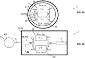
- Figs. 2A and 2B illustrate different examples of the implantable hearing aid system 1, wherein the hearing aid (2,2A,2B) includes a voltage decreasing converter 24 configured to decrease a voltage of the power signals received from the charger unit 3 for use in charging the rechargeable battery 4, and a voltage increasing converter 26 configured to increase a voltage of signals obtained from the rechargeable battery 4.
- the voltage increasing and decreasing converter (24, 26) are arranged within an area encircled by the inductive coil arrangement 6 or in vicinity to the center of the inductive coil arrangement 6.
- the voltage increasing and decreasing converter (24, 26) are arranged within a housing 12 of the hearing aid 2B, and the inductive coil arrangement 6 is arranged externally to the housing 12.
- the hearing aid (2, 2A, 2B) includes a capacitive circuit arrangement (20, 200) configured to adjust the resonance frequency of the inductive coil arrangement to a plurality of resonance frequencies including at least the second resonance frequency and the third resonance frequency.
- the hearing aid (2, 2A, 2B) includes a processor 22 configured to transmit a control signal to the capacitive circuit arrangement (20,200).
- the capacitive circuit arrangement (20) may include at least one of a first switched capacitor 204 and a second switched capacitor 201, wherein the first switched capacitor 204 may be connected in parallel to a first circuitry element 203, and the second switched capacitor 201 may be connected in serial to a second circuitry element 202.
- the resonance frequency of the inductive coil arrangement 6 may be adapted based on the at least one measured of a Q factor of the inductive coil arrangement, or based on a power level measure of a signal received by the inductive coil arrangement, and selectively connecting at least one of the first and second switched capacitors 201, 204 to the circuitry constituting the capacitive circuit arrangement (20).
- the capacitive circuit arrangement (200) includes at least a switch (206A, 206B), a first tuning circuit (20,20A) and at least a second circuit (20,20B), and each of the two tuning circuits (20,20A,20B) is connected to the switch (206A, 206B).
- the switch (206A, 206B) is configured to receive a control signal (208A,208B) and connect (210A,210B) the inductive coil arrangement 6 and the remaining parts (4,22) of the hearing aid (2,2A,2B) to either the first tuning circuit (20,20A) or the second tuning circuit (20,20B) based on the control signal (208A,208B).
- the first tuning circuit (20,20A) is configured to form the transcutaneous link with the implantable coil (not shown) when connected to the inductive coil arrangement 6 via the switch (206A,206B), and wherein the second tuning circuit (20,20B) is configured to form the inductive charging link 10 with the coil unit 8 when connected to the inductive coil arrangement 6 via the switch (206A,206B).
- the control signal may be determined by the processor 22, and the processor is configured to determine the control signal based on a measure of a Q factor of the inductive coil arrangement 6, or the control signal is determined based on a power level measure of a signal received by the inductive coil arrangement 6.
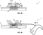
- the inductive coil arrangement 6 may include a magnet 30 configured to align an inductive coil 6A of the inductive coil arrangement 6 to the coil unit 8 of the charger unit 3.
- the charger unit includes a magnet 32 which is arranged such that the coil unit 8 circumference the magnet 32, and the magnet 30 in the inductive coil arrangement 6 is arranged such that the inductive coil 6A circumference the magnet 30.
- the charger unit may have a second magnet, a metal surface or a metal component which is configured to magnetically attract the magnet of the inductive coil arrangement.
- the metal surface or the metal component may be arranged in a center of the coil unit 8, and wherein the center of the coil unit 8 is circumference by coils of the coil unit 8.
- Figs. 5 illustrate the implantable hearing aid system 1, where the charger unit 3 is configured to transmit data to the hearing aid via the inductive charging link 10 or via a second inductive link 51 between the coil unit 8 and the inductive coil arrangement 6, and wherein the transmitted data includes charging data, software update data and/or firmware update data.
- the charger unit 3 may include a far-field communication interface 50 configured to transmit an update acknowledgement signal via the far-field communication interface 50, and, to receive software update data and/or firmware update data via the far-field communication interface 50 based on the update acknowledgement signal.
- the far-field communication interface 50 includes a transceiver interface configured for transmitting and receiving software update data via a communication network 52, and wherein the communication network 52 includes mobile network, a local network and/or a wireless network.
- the local network may include one or more of Bluetootk, Bluetooth Low energy, WIFI etc.
- Figs.6A and 6B illustrates different examples of the capacitive circuit arrangement (20,200).
- the capacitive circuit arrangement (20,200) may be a passive component including at least a first and a second filter (60,61).
- the first filter and the second filter may be a notch filter, a bandpass filter, lowpass filter, short wave filter or any filter type which is suitable for filtering the first, second and third resonance frequencies.
- the capacitive circuit arrangement 200 comprises the first filter 60 and the second filter 61, where both filters (60,61) receives data/power via the connector part 5, and the first filter 60 and the second filter 61 are further connected to the voltage decreasing converter 24 and the voltage increasing converter 26, respectively.
- the first filter 60 is configured to pass through resonance frequencies which is within a frequency range of between 80 kHz to 300 kHz (medium QI charger), 110 kHz and 205 kHz (low power QI chargers).
- the first filter 60 is configured to pass through the first and/or the second resonance frequency and cancel out or reduce the signal level having resonance frequencies which is outside the frequency range.
- the first filter 60 is configured to cancel out or reduce the signal level having resonance frequencies which is within a frequency range of 4 MHz to 6.5 MHz, 4 MHz to 10 MHz, or 4 MHz to 12 MHz.
- the first filter 60 is configured to cancel out or reduce the signal level about the third resonance frequency.
- the second filter 61 is configured to pass through resonance frequencies which is within a frequency range of between 4 MHz to 6.5 MHz, 4 MHz to 10 MHz, or 4 MHz to 12 MHz.
- the second filter 61 is configured to pass through the third resonance frequency and cancel out or reduce the signal level having resonance frequencies which is outside the frequency range.
- the second filter 61 is configured to cancel out or reduce the signal level having resonance frequencies which is within a frequency range of between 80 kHz to 300 kHz (medium QI charger), 110 kHz and 205 kHz (low power QI chargers).
- the second filter 61 is configured to cancel out or reduce the signal level about the first and/or the second resonance frequency.
Landscapes
- Engineering & Computer Science (AREA)
- Signal Processing (AREA)
- Computer Networks & Wireless Communication (AREA)
- Health & Medical Sciences (AREA)
- General Health & Medical Sciences (AREA)
- Otolaryngology (AREA)
- Power Engineering (AREA)
- Physics & Mathematics (AREA)
- Neurosurgery (AREA)
- Acoustics & Sound (AREA)
- Biomedical Technology (AREA)
- Nuclear Medicine, Radiotherapy & Molecular Imaging (AREA)
- Radiology & Medical Imaging (AREA)
- Life Sciences & Earth Sciences (AREA)
- Animal Behavior & Ethology (AREA)
- Public Health (AREA)
- Veterinary Medicine (AREA)
- Charge And Discharge Circuits For Batteries Or The Like (AREA)
Abstract
Description
- The present disclosure relates to an implantable hearing aid system for charging and updating a hearing aid via an inductive coil arrangement.
- An implantable hearing aid system for improving a hearing-impaired person's capability to hear may impose either electrical stimulation of a cochlea of the person or vibration applied on to the skull of the person, or a combination of the electrical stimulation and vibration. In most cases, the implantable hearing aid system includes a hearing aid, such as an external component, placed on or at the head of the person and an implantable component arranged between the skin and the skull of the person. The implantable component applies the electrical stimulation and/or the vibration. In any of the mentioned cases, a rechargeable battery may be arranged in the hearing aid, and in that case, a charger is needed for recharging the rechargeable battery. There exists a variety of conventional wireless technology standards for charging Li-Ion and other batteries which today becomes more accessible in the way of being built into furniture, electronic articles, and other elements that are around us. An example of a conventional wireless technology standard is the QI standard which defines a wireless power transfer using inductive charging.
- Thus, it is known to make a charger configured for recharging a rechargeable battery of an implantable hearing aid when reading
US 2017/0040841 A1 , however, the disadvantage with the disclosed solution is that the charger is not part of a conventional wireless technology standard, as for example the QI standard, instead the charger is customized specifically for a specific implantable hearing aid. Thereby, the likelihood of being able to recharge the disclosed implantable hearing aid is significantly less when your away from home and have not brought the customized charger with you. - Thereby, it is a need for having an implantable hearing aid which is configured to be recharged via a conventional wireless technology standard.
- An aspect of the disclosure is to provide an implantable hearing aid system which applies recharging of a hearing aid via a conventional wireless technology standard for improving the accessibility to a charger unit when being away from home, and where the charger unit is configured to recharge once hearing aid.
- A further aspect of the disclosure is to provide an implantable hearing aid system which applies software updating of a hearing aid via an inductive coil arrangement also used for recharging.
- According to one or more of the mentioned aspects, the implantable hearing aid system comprises a charger unit which includes a coil unit having a first resonance frequency, a hearing aid and an implantable component. The hearing aid includes a rechargeable battery, an inductive coil arrangement having a second resonance frequency configured to form an inductive charging link with the coil unit to receive power signals from the charger unit. The implantable component includes an implantable coil, wherein the inductive coil arrangement may further be configured to form a transcutaneous link with the implantable coil to transmit at least one of data and power to the implantable component.
- The first resonance frequency and the second resonance frequency are matched or partly matched in order for the inductive coil arrangement to be configured to receive and/or transmit data and/or power via the inductive charging link which may be part of a conventional wireless technology standard, such as the QI standard.
- The inductive coil arrangement may be arranged externally to a housing including the hearing aid, and where the inductive coil arrangement is connected to the housing via a connector part which includes one or more wires.
- The inductive coil arrangement may be arranged within a housing of the hearing aid.
- The inductive coil arrangement may be connected to the remaining parts of the hearing aid via a connector part which includes one or more wires.
- The connector part may be a flexible tube which allows the hearing aid to be placed, for example behind an ear of the user, while placing the inductive coil arrangement on the skin of the head of the user.
- Furthermore, the hearing aid includes a voltage decreasing converter configured to decrease a voltage of the power signals received from the charger unit for use in charging the rechargeable battery, and a voltage increasing converter configured to increase a voltage of signals obtained from the rechargeable battery.
- As the first resonance frequency and the second resonance frequency are matched or partly matched, the inductive charging link is highly effective providing more voltage than what is acceptable for a rechargeable battery in a hearing aid, and in that case, it is a need to have the voltage decreasing converter in the hearing aid for decreasing the voltage of the power signals provided by the charger unit. Thereby, the lifetime of the rechargeable battery is not shortened due to overvoltage charging.
- The rechargeable battery may include lead-acid, nickel-cadmium (NiCd), nickel-metal hydride (NiMH), lithium-ion (Li-ion), or lithium-ion polymer (Li-ion polymer).
- Furthermore, when the hearing aid is used for communicating with the implantable component via the transcutaneous link, the hearing aid receives voltage signals from the rechargeable battery, and in that case, the voltage of signals obtained from the rechargeable battery needs to be increased via the voltage increasing converter, otherwise, no communication and/or power transfer would be robustly and/or efficiently established via the transcutaneous link.
- The first resonance frequency and the second resonance frequency are within a frequency range of between 80 kHz to 300 kHz, or between 110 kHz and 205 kHz. The hearing aid is configured to shift between the two frequency ranges based on the type of the charger unit. For example, a charger unit which operates between 80 kHz to 300 kHz is characterized as being a medium power QI charger, and a charger unit which operates between 110 KHz and 205 kHZ is characterized as being a low power QI charger. A low power QI charger delivers up to 5 watts, and a medium power QI charger delivers up to 120 watts.
- So, if the user of the hearing aid has at hand a low power QI charger unit, the user is able to configure the second resonance frequency to the frequency range of 110kHz to 205 kHZ, and vice versa, for a medium power QI charger unit. The user may shift between the two ranges via a user interface of the hearing aid or via a user interface of an external communication device, such as a smartphone, a smart watch etc.
- In order to secure a stable inductive charging link between the charger unit and the hearing aid, the inductive coil arrangement may include a magnet configured to align an inductive coil of the inductive coil arrangement to the coil unit of the charger unit.
- The charger unit may have, a magnet, a metal surface or a metal component which is configured to magnetically attract the magnet of the inductive coil arrangement.
- The metal surface or the metal component may be arranged in a center of the coil unit, and wherein the center of the coil unit is circumference by coils of the coil unit.
- The inductive coil arrangement may have a third resonance frequency being in resonance to a resonance frequency of the implantable coil, and the third resonance frequency may be within a frequency range of 4 MHz to 6.5 MHz, 4 MHz to 10 MHz, or 4 MHz to 12 MHz. The defined frequency ranges are suitable for establishing a transcutaneous link and not for establishing an inductive charging link which may be part of a conventional wireless technology standard, such as the QI standard.
- The hearing aid may include a capacitive circuit arrangement configured to adjust the resonance frequency of the inductive coil arrangement to a plurality of resonance frequencies including at least the second resonance frequency. The capacitive circuit arrangement may be connected to the inductive coil arrangement, the voltage decreasing converter and the voltage increasing converter.
- The capacitive circuit arrangement may include a plurality of capacitors, and where one or more capacitor of the plurality of capacitors has a contact configured to couple and decouple the one or more capacitor, such that when the capacitor is decoupled, the capacitor is not actively part of the capacitive circuit arrangement, and when the capacitor is coupled, the capacitor is actively part of the capacitive circuit arrangement.
- Position of the contact may be controlled based on a measure of a Q factor of the inductive coil arrangement or based on a power level measure of a signal received by the inductive coil arrangement.
- Position of the contact for the one or more capacitors may be controlled by selecting a resonance frequency via a user interface of the hearing aid or of an external communication device, such as a smartphone, a smartwatch etc.
- The hearing aid may include a processor configured to transmit a control signal to the capacitive circuit arrangement, and wherein the capacitive circuit arrangement includes a switch, a first tuning circuit and at least a second circuit, and each of the two tuning circuits may be connected to the switch, and the switch may be configured to receive the control signal, and wherein the switch may be configured to connect the inductive coil arrangement to either the first tuning circuit or the second tuning circuit based on the control signal. Thereby, the hearing aid's ability to adjust the resonance frequency of the inductive coil arrangement is improved.
- The processor may be part of an external communication device, such as a smartphone, a smart watch etc.
- The first tuning circuit may be configured to form the transcutaneous link with the implantable coil when connected to the inductive coil arrangement via the switch, and the second tuning circuit may be configured to form the inductive charging link with the coil unit when connected to the inductive coil arrangement via the switch.
- The capacitive circuit-arrangement may include at least a first filter and a first tuning circuit, where the first filter and the first tuning circuit are connected. The capacitive circuit arrangement may include a second filter and a second tuning circuit, where the second filter and the second tuning circuit are connected. The first tuning circuit may be connected to the inductive coil arrangement, where the first filter, the first tuning circuit and the inductive coil arrangement are configured to form the transcutaneous link with the implantable coil. The second tuning circuit may be connected to the inductive coil arrangement, where the second filter, the second tuning circuit and the inductive coil arrangement are configured to form the inductive charging link with the coil unit.
- Both filters, i.e. the first filter and the second filter, may be configured to separate between charging power transmitted by a charging unit and power/data to be transmitted
- Both filters may be a notch filter comprising a one or more capacitors and one or more inductances.
- For example, the first filter may have a resonance frequency at around 6.78 MHz, and the second filter may have a resonance frequency at around 140 kHz.
- The control signal may be determined based on a measure of a Q factor of the inductive coil arrangement, or the control signal is determined based on a power level measure of a signal received by the inductive coil arrangement.
- The control signal may be determined based on a user interface of the hearing aid or an external communication device.
- By being able to determine the control signal and/or the position of the contacts by the measure of the Q factor or by the measure of the power level allows for an automatically adjustment of resonance frequency of the inductive coil arrangement.
- By being able to determine the control signal and/or the position of the contacts by an input via the user interface allows a simpler solution for adjusting the resonance frequency of the inductive coil arrangement.
- The hearing aid may include a first antenna configured to form a communication link to a second antenna of the charger unit for communicating charging data. The communication link may be based on Bluetooth or Bluetooth low energy. The charging data may include charge capacity information or temperature of the rechargeable battery
- The charger unit may be configured to transmit data to the hearing aid via the inductive charging link or via a second inductive link between the coil unit and the inductive coil arrangement, and wherein the transmitted data includes charging data, software update data and/or firmware update data. Thereby, it is possible to update the software or firmware of the hearing aid while being charged. This allows the possibility of updating the hearing aid at home. Furthermore, by utilizing the inductive coil arrangement secures a more compact solution of the hearing aid while reusing the inductive coil arrangement for multiple purposes. Furthermore, if using a second antenna for updating the hearing aid, the hearing aid is in need for using power from the battery for driving the second antenna, and that results in a longer charging time. Thereby, by utilizing the inductive coil arrangement for multiple purposes, such as charging and updating, would result in a shorter charging time compared to the example where you have the second antenna.
- The plurality of resonance frequencies may include a fourth resonance frequency for the second inductive link.
- The charger unit may include a far-field communication interface configured to transmit an update acknowledgement signal via the far-field communication interface, and, to receive software update data and/or firmware update data via the far-field communication interface based on the update acknowledgement signal.
- The update acknowledgement signal includes information data about the hearing aid, such as identification data.
- The far-field communication interface may include a transceiver interface configured for transmitting and receiving software update data via a communication network, and wherein the communication network includes mobile network, a local network and/or a wireless network.
- The aspects of the disclosure may be best understood from the following detailed description taken in conjunction with the accompanying figures. The figures are schematic and simplified for clarity, and they just show details to improve the understanding of the claims, while other details are left out. Throughout, the same reference numerals are used for identical or corresponding parts. The individual features of each aspect may each be combined with any or all features of the other aspects. These and other aspects, features and/or technical effect will be apparent from and elucidated with reference to the illustrations described hereinafter in which:
- Figs. 1A and 1B
- illustrate different examples of an implantable hearing aid system;
- Figs. 2A to 2B
- illustrate different examples of an implantable hearing aid system;
- Figs. 3A and 3B
- illustrate different examples of a capacitive circuit arrangement;
- Figs. 4A and 4B
- illustrate different examples of an implantable hearing aid system;
- Fig. 5
- illustrate an example of an implantable hearing aid system; and
- Figs. 6A and 6B
- illustrate different example of a capacitive circuit arrangement.
- The detailed description set forth below in connection with the appended drawings is intended as a description of various configurations. The detailed description includes specific details for the purpose of providing a thorough understanding of various concepts. However, it will be apparent to those skilled in the art that these concepts may be practiced without these specific details. Several aspects of the apparatus and methods are described by various blocks, functional units, modules, components, etc. (collectively referred to as "elements"). Depending upon particular application, design constraints or other reasons, these elements may be implemented using other equivalent elements.
- A hearing aid is adapted to improve or augment the hearing capability of a user by receiving an acoustic signal from a user's surroundings, generating a corresponding audio signal, possibly modifying the audio signal and providing the possibly modified audio signal as an audible signal to at least one of the user's ears. Such audible signals may be provided in the form of an acoustic signal transferred as mechanical vibrations to the user's inner ears through bone structure of the user's head.
- The hearing aid may be replaced by a system comprising one or two hearing aids, and a "binaural hearing system" refers to a system comprising two hearing aids where the devices are adapted to cooperatively provide audible signals to both of the user's ears or the hearing aid of bone conduction type may be part of a bimodal system comprising a cochlea implant and a bone conduction hearing aid. The system may further include auxiliary device(s) that communicates with at least one hearing aid, the auxiliary device affecting the operation of the hearing aids and/or benefitting from the functioning of the hearing aids. A wired or wireless communication link between the at least one hearing aid and the auxiliary device is established that allows for exchanging information (e.g. control and status signals, possibly audio signals) between the at least one hearing aid and the auxiliary device. Such auxiliary devices may include at least one of remote controls, remote microphones, audio gateway devices, mobile phones, public-address systems, car audio systems or music players or a combination thereof. The audio gateway is adapted to receive a multitude of audio signals such as from an entertainment device like a TV or a music player, a telephone apparatus like a mobile telephone or a computer, a PC. The audio gateway is further adapted to select and/or combine an appropriate one of the received audio signals (or combination of signals) for transmission to the at least one hearing aid. The remote control is adapted to control functionality and operation of the at least one hearing aids. The function of the remote control may be implemented in a SmartPhone or other electronic device, the SmartPhone/ electronic device possibly running an application that controls functionality of the at least one hearing aid.
- In general, a hearing aid includes i) an input unit such as a microphone for receiving an acoustic signal from a user's surroundings and providing a corresponding input audio signal, and/or ii) a receiving unit for electronically receiving an input audio signal. The hearing aid further includes a signal processing unit for processing the input audio signal and an output unit for providing an audible signal to the user in dependence on the processed audio signal.
- The input unit may include multiple input microphones, e.g. for providing direction-dependent audio signal processing. Such directional microphone system is adapted to enhance a target acoustic source among a multitude of acoustic sources in the user's environment. In one aspect, the directional system is adapted to detect (such as adaptively detect) from which direction a particular part of the microphone signal originates. This may be achieved by using conventionally known methods. The signal processing unit may include amplifier that is adapted to apply a frequency dependent gain to the input audio signal. The signal processing unit may further be adapted to provide other relevant functionality such as compression, noise reduction, etc. The output unit may include an output transducer for providing mechanical vibrations either transcutaneously or percutaneously to the skull bone.
-
Figs. 1A and 1B illustrate different examples of an implantablehearing aid system 1, wherein the implantablehearing aid system 1 comprises acharger unit 3 including acoil unit 8 having a first resonance frequency. Furthermore, thesystem 1 includes a hearing aid (2,2A,2B) which comprises arechargeable battery 4, aninductive coil arrangement 6 having a second resonance frequency configured to form aninductive charging link 10 with thecoil unit 8 to receive power signals from thecharger unit 3. Additionally, thesystem 1 includes an implantable component (not shown) which includes an implantable coil, wherein the inductive coil arrangement is further configured to form a transcutaneous link with the implantable coil to transmit at least one of data and power to the implantable component, and wherein the first resonance frequency and the second resonance frequency are matched or partly matched. InFig. 1A , theinductive coil arrangement 6 is arranged within ahousing 12 of the hearing aid 2, and inFig. 1B , theinductive coil arrangement 6 is arranged externally to thehousing 12 of thehearing aid 2B. InFig. 1B , theinductive coil arrangement 6 is connected to thehousing 12 via aconnector part 5 which includes one or more wires for transferring data and power between theinductive coil arrangement 6 and thehearing aid 2B. -
Figs. 2A and 2B illustrate different examples of the implantablehearing aid system 1, wherein the hearing aid (2,2A,2B) includes avoltage decreasing converter 24 configured to decrease a voltage of the power signals received from thecharger unit 3 for use in charging therechargeable battery 4, and avoltage increasing converter 26 configured to increase a voltage of signals obtained from therechargeable battery 4. InFig. 2A , at least therechargeable battery 4, the voltage increasing and decreasing converter (24, 26) are arranged within an area encircled by theinductive coil arrangement 6 or in vicinity to the center of theinductive coil arrangement 6. InFig. 2B at least therechargeable battery 4, the voltage increasing and decreasing converter (24, 26) are arranged within ahousing 12 of thehearing aid 2B, and theinductive coil arrangement 6 is arranged externally to thehousing 12. - In
Figs. 2A and 2B , the hearing aid (2, 2A, 2B) includes a capacitive circuit arrangement (20, 200) configured to adjust the resonance frequency of the inductive coil arrangement to a plurality of resonance frequencies including at least the second resonance frequency and the third resonance frequency. - In
Figs. 2A and 2B , the hearing aid (2, 2A, 2B) includes aprocessor 22 configured to transmit a control signal to the capacitive circuit arrangement (20,200). -
Figs. 3A and 3B illustrates different examples of the capacitive circuit arrangement (20,200). InFig. 3A , the capacitive circuit arrangement (20) may include at least one of a first switchedcapacitor 204 and a second switchedcapacitor 201, wherein the first switchedcapacitor 204 may be connected in parallel to afirst circuitry element 203, and the second switchedcapacitor 201 may be connected in serial to a second circuitry element 202. Further, the resonance frequency of theinductive coil arrangement 6 may be adapted based on the at least one measured of a Q factor of the inductive coil arrangement, or based on a power level measure of a signal received by the inductive coil arrangement, and selectively connecting at least one of the first and second switchedcapacitors - In
Fig. 3B , the capacitive circuit arrangement (200) includes at least a switch (206A, 206B), a first tuning circuit (20,20A) and at least a second circuit (20,20B), and each of the two tuning circuits (20,20A,20B) is connected to the switch (206A, 206B). The switch (206A, 206B) is configured to receive a control signal (208A,208B) and connect (210A,210B) theinductive coil arrangement 6 and the remaining parts (4,22) of the hearing aid (2,2A,2B) to either the first tuning circuit (20,20A) or the second tuning circuit (20,20B) based on the control signal (208A,208B). - The first tuning circuit (20,20A) is configured to form the transcutaneous link with the implantable coil (not shown) when connected to the
inductive coil arrangement 6 via the switch (206A,206B), and wherein the second tuning circuit (20,20B) is configured to form theinductive charging link 10 with thecoil unit 8 when connected to theinductive coil arrangement 6 via the switch (206A,206B). - The control signal may be determined by the
processor 22, and the processor is configured to determine the control signal based on a measure of a Q factor of theinductive coil arrangement 6, or the control signal is determined based on a power level measure of a signal received by theinductive coil arrangement 6. -
Figs 4A and 4B illustrate different examples of the implantablehearing aid system 1, theinductive coil arrangement 6 may include amagnet 30 configured to align an inductive coil 6A of theinductive coil arrangement 6 to thecoil unit 8 of thecharger unit 3. InFig. 4A , the charger unit includes amagnet 32 which is arranged such that thecoil unit 8 circumference themagnet 32, and themagnet 30 in theinductive coil arrangement 6 is arranged such that the inductive coil 6A circumference themagnet 30. - In
Fig. 4B , the charger unit may have a second magnet, a metal surface or a metal component which is configured to magnetically attract the magnet of the inductive coil arrangement. The metal surface or the metal component may be arranged in a center of thecoil unit 8, and wherein the center of thecoil unit 8 is circumference by coils of thecoil unit 8. -
Figs. 5 illustrate the implantablehearing aid system 1, where thecharger unit 3 is configured to transmit data to the hearing aid via theinductive charging link 10 or via a secondinductive link 51 between thecoil unit 8 and theinductive coil arrangement 6, and wherein the transmitted data includes charging data, software update data and/or firmware update data. - The
charger unit 3 may include a far-field communication interface 50 configured to transmit an update acknowledgement signal via the far-field communication interface 50, and, to receive software update data and/or firmware update data via the far-field communication interface 50 based on the update acknowledgement signal. - The far-
field communication interface 50 includes a transceiver interface configured for transmitting and receiving software update data via acommunication network 52, and wherein thecommunication network 52 includes mobile network, a local network and/or a wireless network. - The local network may include one or more of Bluetootk, Bluetooth Low energy, WIFI etc.
-
Figs.6A and 6B illustrates different examples of the capacitive circuit arrangement (20,200). InFig. 6A , the capacitive circuit arrangement (20,200) may be a passive component including at least a first and a second filter (60,61). - The first filter and the second filter may be a notch filter, a bandpass filter, lowpass filter, short wave filter or any filter type which is suitable for filtering the first, second and third resonance frequencies. In
Fig. 6B , thecapacitive circuit arrangement 200 comprises thefirst filter 60 and thesecond filter 61, where both filters (60,61) receives data/power via theconnector part 5, and thefirst filter 60 and thesecond filter 61 are further connected to thevoltage decreasing converter 24 and thevoltage increasing converter 26, respectively. - The
first filter 60 is configured to pass through resonance frequencies which is within a frequency range of between 80 kHz to 300 kHz (medium QI charger), 110 kHz and 205 kHz (low power QI chargers). For example, thefirst filter 60 is configured to pass through the first and/or the second resonance frequency and cancel out or reduce the signal level having resonance frequencies which is outside the frequency range. For example, thefirst filter 60 is configured to cancel out or reduce the signal level having resonance frequencies which is within a frequency range of 4 MHz to 6.5 MHz, 4 MHz to 10 MHz, or 4 MHz to 12 MHz. Thefirst filter 60 is configured to cancel out or reduce the signal level about the third resonance frequency. - The
second filter 61 is configured to pass through resonance frequencies which is within a frequency range of between 4 MHz to 6.5 MHz, 4 MHz to 10 MHz, or 4 MHz to 12 MHz. For example, thesecond filter 61 is configured to pass through the third resonance frequency and cancel out or reduce the signal level having resonance frequencies which is outside the frequency range. For example, thesecond filter 61 is configured to cancel out or reduce the signal level having resonance frequencies which is within a frequency range of between 80 kHz to 300 kHz (medium QI charger), 110 kHz and 205 kHz (low power QI chargers).Thesecond filter 61 is configured to cancel out or reduce the signal level about the first and/or the second resonance frequency. - As used, the singular forms "a," "an," and "the" are intended to include the plural forms as well (i.e. to have the meaning "at least one"), unless expressly stated otherwise. It will be further understood that the terms "includes," "comprises," "including," and/or "comprising," when used in this specification, specify the presence of stated features, elements, components, and/or steps but do not preclude the presence or addition of one or more other features, elements, components, and/or steps thereof. It will also be understood that when an element is referred to as being "connected" or "coupled" to another element, it can be directly connected or coupled to the other element, but an intervening element may also be present, unless expressly stated otherwise. As used herein, the term "and/or" includes any and all combinations of one or more of the associated listed items. The steps of any disclosed method are not limited to the exact order stated herein, unless expressly stated otherwise.
- It should be appreciated that reference throughout this specification to "one embodiment" or "an embodiment" or "an aspect" or features included as "may" means that a particular feature, structure or characteristic described in connection with the embodiment is included in at least one embodiment of the disclosure. Furthermore, the particular features, structures or characteristics may be combined as suitable in one or more embodiments of the disclosure. The previous description is provided to enable any person skilled in the art to practice the various aspects described herein. Various modifications to these aspects will be readily apparent to those skilled in the art, and the generic principles defined herein may be applied to other aspects.
- The scope should be judged in terms of the claims that follow.
Claims (17)
- An implantable hearing aid system, comprising:a charger unit including a coil unit having a first resonance frequency,a hearing aid, including:a rechargeable battery,an inductive coil arrangement having a second resonance frequency configured to form an inductive charging link with the coil unit to receive power signals from the charger unit,a voltage decreasing converter configured to decrease a voltage of the power signals received from the charger unit for use in charging the rechargeable battery, anda voltage increasing converter configured to increase a voltage of signals obtained from the rechargeable battery, andan implantable component including an implantable coil, wherein the inductive coil arrangement is further configured to form a transcutaneous link with the implantable coil to transmit at least one of data and power to the implantable component, and wherein the first resonance frequency and the second resonance frequency are matched or partly matched.
- An implantable hearing aid system according to claim 1, wherein the first resonance frequency and the second resonance frequency are within a frequency range of between 80 kHz to 300 kHz (medium QI charger), 110 kHz and 205 kHz (low power QI chargers).
- An implantable hearing aid system according to any of the previous claims, wherein the inductive coil arrangement includes a magnet configured to align an inductive coil of the inductive coil arrangement to the coil unit of the charger unit.
- An implantable hearing aid system according to any of the previous claims, wherein the inductive coil arrangement having a third resonance frequency being in resonance to a resonance frequency of the implantable coil.
- An implantable hearing aid system according to claim4, wherein the third resonance frequency is within a frequency range of 4 MHz to 6.5 MHz, 4 MHz to 10 MHz, or 4 MHz to 12 MHz.
- An implantable hearing aid system according to any of the previous claims, wherein the hearing aid includes a capacitive circuit arrangement configured to adjust the resonance frequency of the inductive coil arrangement to a plurality of resonance frequencies including at least the second resonance frequency.
- An implantable hearing aid system according to claim 5, wherein the hearing aid includes a processor configured to transmit a control signal to the capacitive circuit arrangement, and wherein the capacitive circuit arrangement includes at least a switch, a first tuning circuit and at least a second circuit, and each of the two tuning circuits is connected to the switch, and the switch is configured to receive the control signal, and wherein the switch is configured to connect the inductive coil arrangement to either the first tuning circuit or the second tuning circuit based on the control signal.
- An implantable hearing aid system according to claim 7, wherein the first tuning circuit is configured to form the transcutaneous link with the implantable coil when connected to the inductive coil arrangement via the switch, and wherein the second tuning circuit is configured to form the inductive charging link with the coil unit when connected to the inductive coil arrangement via the switch.
- An implantable hearing aid system according to any of claims 7 to 8, wherein the control signal is determined based on a measure of a Q factor of the inductive coil arrangement, or the control signal is determined based on a power level measure of a signal received by the inductive coil arrangement.
- An implantable hearing aid system according to any of the previous claims, wherein the hearing aid includes a first antenna configured to form a communication link to a second antenna of the charger unit for communicating charging data.
- An implantable hearing aid system according to claim 10, wherein the charging data includes charge capacity information or temperature of the rechargeable battery.
- An implantable hearing aid system according to any of the previous claims, wherein the charger unit is configured to transmit data to the hearing aid via the inductive charging link or via a second inductive link between the coil unit and the inductive coil arrangement, and wherein the transmitted data includes charging data, software update data and/or firmware update data.
- An implantable hearing aid system according to claim 12, wherein the plurality of resonance frequencies includes a fourth resonance frequency for the second inductive link.
- An implantable hearing aid system according to any of claims 12 and 13, wherein the charger unit includes a far-field communication interface configured to transmit an update acknowledgement signal via the far-field communication interface, and, to receive software update data and/or firmware update data via the far-field communication interface based on the update acknowledgement signal.
- An implantable hearing aid system according to claim 14, wherein the update acknowledgement signal includes information data about the hearing aid.
- An implantable hearing aid system according to any of claims 12 to 15, wherein the far-field communication interface includes a transceiver interface configured for transmitting and receiving software update data via a communication network, and wherein the communication network includes mobile network, a local network and/or a wireless network.
- An implantable hearing aid system according to any of claims 1 to 5 and 10 to 16, wherein the hearing aid includes a capacitive circuit arrangement, wherein the capacitive circuit arrangement includes:at least a first filter and a second filter,at least a first tuning circuit and a second tuning circuit, wherein both tuning circuits are connected to the inductive coil arrangement, andwherein the at least first filter is connected to the first tuning circuit configured to form the transcutaneous link, and the second filter is connected to the second tuning circuit configured to form the inductive charging link.
Applications Claiming Priority (1)
| Application Number | Priority Date | Filing Date | Title |
|---|---|---|---|
| US16/778,980 US11606648B2 (en) | 2020-01-31 | 2020-01-31 | Charging and updating of an implantable hearing aid |
Publications (3)
| Publication Number | Publication Date |
|---|---|
| EP3858431A1 true EP3858431A1 (en) | 2021-08-04 |
| EP3858431B1 EP3858431B1 (en) | 2025-10-29 |
| EP3858431C0 EP3858431C0 (en) | 2025-10-29 |
Family
ID=74194555
Family Applications (1)
| Application Number | Title | Priority Date | Filing Date |
|---|---|---|---|
| EP21152525.8A Active EP3858431B1 (en) | 2020-01-31 | 2021-01-20 | Charging and updating of an implantable hearing aid |
Country Status (4)
| Country | Link |
|---|---|
| US (1) | US11606648B2 (en) |
| EP (1) | EP3858431B1 (en) |
| CN (1) | CN113285530B (en) |
| AU (1) | AU2021200591B2 (en) |
Cited By (2)
| Publication number | Priority date | Publication date | Assignee | Title |
|---|---|---|---|---|
| EP3886289A1 (en) * | 2020-03-23 | 2021-09-29 | Sonova AG | Hearing device |
| US12574692B2 (en) | 2021-09-15 | 2026-03-10 | Gn Hearing A/S | Wirelessly rechargeable hearing device and charger for same |
Families Citing this family (3)
| Publication number | Priority date | Publication date | Assignee | Title |
|---|---|---|---|---|
| US20220377473A1 (en) * | 2021-05-18 | 2022-11-24 | Oticon A/S | Method for charging at least one hearing device and a hearing aid system |
| DE102023207237A1 (en) * | 2023-07-28 | 2025-01-30 | Sivantos Pte. Ltd. | Method for operating an inductive charger of a hearing aid and inductive charger of a hearing aid |
| WO2025088448A1 (en) * | 2023-10-27 | 2025-05-01 | Medtronic, Inc. | Augmented power system for implantable medical device |
Citations (4)
| Publication number | Priority date | Publication date | Assignee | Title |
|---|---|---|---|---|
| US20120150259A1 (en) * | 2010-12-10 | 2012-06-14 | Werner Meskens | Portable power charging of implantable medical devices |
| US20140114373A1 (en) * | 2012-10-22 | 2014-04-24 | Boston Scientific Neuromodulation Corporation | Intermediate Coupler to Facilitate Charging in an Implantable Medical Device System |
| US20170040841A1 (en) | 2015-08-03 | 2017-02-09 | Oliver John Ridler | Implantable medical device charging |
| US20180272131A1 (en) * | 2017-03-22 | 2018-09-27 | Werner Meskens | Autonomous implantable medical device tuning |
Family Cites Families (18)
| Publication number | Priority date | Publication date | Assignee | Title |
|---|---|---|---|---|
| DE4104359A1 (en) * | 1991-02-13 | 1992-08-20 | Implex Gmbh | CHARGING SYSTEM FOR IMPLANTABLE HOERHILFEN AND TINNITUS MASKERS |
| DE10015421C2 (en) * | 2000-03-28 | 2002-07-04 | Implex Ag Hearing Technology I | Partially or fully implantable hearing system |
| WO2004027955A2 (en) * | 2002-09-19 | 2004-04-01 | Quallion Llc | Battery charging system |
| US8948426B2 (en) * | 2006-02-17 | 2015-02-03 | Zounds Hearing, Inc. | Method for calibrating a hearing aid |
| US9227075B2 (en) * | 2008-12-03 | 2016-01-05 | Boston Scientific Neuromodulation Corporation | External charger with adjustable alignment indicator |
| CN202799146U (en) * | 2009-09-08 | 2013-03-13 | 西门子医疗器械公司 | Hearing aid with wireless battery charging function |
| US8577474B2 (en) * | 2009-11-11 | 2013-11-05 | Boston Scientific Neuromodulation Corporation | Minimizing interference between charging and telemetry coils in an implantable medical device |
| WO2014018967A1 (en) * | 2012-07-27 | 2014-01-30 | Thoratec Corporation | Self-tuning resonant power transfer systems |
| US9793740B2 (en) * | 2012-11-26 | 2017-10-17 | Samsung Electronics Co., Ltd. | Apparatus and method for charge control in wireless charging system |
| JP2015073167A (en) * | 2013-10-02 | 2015-04-16 | 日東電工株式会社 | Hearing aid and hearing aid charging system |
| NL2012543B1 (en) * | 2014-04-01 | 2016-02-15 | Audionova Int B V | Mobile wireless controller for a hearing aid. |
| CN106134029B (en) * | 2014-04-16 | 2018-09-25 | 三菱电机株式会社 | Vehicle charger |
| US11103715B2 (en) * | 2014-06-27 | 2021-08-31 | Cochlear Limited | Devices and methods for charging medical devices |
| US20160094922A1 (en) * | 2014-09-29 | 2016-03-31 | Oticon A/S | Positioned hearing system |
| US10555095B2 (en) * | 2016-08-24 | 2020-02-04 | Cochlear Limited | Hearing aid adapter |
| EP3319215B1 (en) * | 2016-11-03 | 2020-12-23 | GN Hearing A/S | Hearing instrument comprising switched capacitor dc-dc power converter |
| EP3441111B1 (en) * | 2017-08-11 | 2020-09-09 | Oticon Medical A/S | Implantable medical device comprising a wireless transcutaneous link |
| WO2019142079A1 (en) * | 2018-01-16 | 2019-07-25 | Cochlear Limited | Ear canal microphone utilizing communications with hearing implant |
-
2020
- 2020-01-31 US US16/778,980 patent/US11606648B2/en active Active
-
2021
- 2021-01-20 EP EP21152525.8A patent/EP3858431B1/en active Active
- 2021-01-29 CN CN202110128023.0A patent/CN113285530B/en active Active
- 2021-01-29 AU AU2021200591A patent/AU2021200591B2/en active Active
Patent Citations (4)
| Publication number | Priority date | Publication date | Assignee | Title |
|---|---|---|---|---|
| US20120150259A1 (en) * | 2010-12-10 | 2012-06-14 | Werner Meskens | Portable power charging of implantable medical devices |
| US20140114373A1 (en) * | 2012-10-22 | 2014-04-24 | Boston Scientific Neuromodulation Corporation | Intermediate Coupler to Facilitate Charging in an Implantable Medical Device System |
| US20170040841A1 (en) | 2015-08-03 | 2017-02-09 | Oliver John Ridler | Implantable medical device charging |
| US20180272131A1 (en) * | 2017-03-22 | 2018-09-27 | Werner Meskens | Autonomous implantable medical device tuning |
Cited By (2)
| Publication number | Priority date | Publication date | Assignee | Title |
|---|---|---|---|---|
| EP3886289A1 (en) * | 2020-03-23 | 2021-09-29 | Sonova AG | Hearing device |
| US12574692B2 (en) | 2021-09-15 | 2026-03-10 | Gn Hearing A/S | Wirelessly rechargeable hearing device and charger for same |
Also Published As
| Publication number | Publication date |
|---|---|
| EP3858431B1 (en) | 2025-10-29 |
| US20210243532A1 (en) | 2021-08-05 |
| CN113285530A (en) | 2021-08-20 |
| US11606648B2 (en) | 2023-03-14 |
| AU2021200591A1 (en) | 2021-08-19 |
| AU2021200591B2 (en) | 2025-11-27 |
| EP3858431C0 (en) | 2025-10-29 |
| CN113285530B (en) | 2026-04-28 |
Similar Documents
| Publication | Publication Date | Title |
|---|---|---|
| EP3858431B1 (en) | Charging and updating of an implantable hearing aid | |
| US7548040B2 (en) | Wireless battery charging of electronic devices such as wireless headsets/headphones | |
| US10595139B2 (en) | Cochlear hearing device with cable antenna | |
| EP4093054A1 (en) | A method for charging at least one hearing device and a hearing aid system | |
| JP6304649B2 (en) | Portable charging of implantable medical devices | |
| US11483667B2 (en) | Hearing device including an external antenna part and an internal antenna part | |
| US10966036B2 (en) | Hearing device including an external antenna and an internal parasitic element | |
| EP4000277B1 (en) | System for charging an ear-worn electronic device | |
| US20250080929A1 (en) | Antenna for a bone-anchored hearing aid | |
| US11399244B2 (en) | Hearing instrument | |
| EP3621317A1 (en) | Hearing aid with automatic antenna tuning | |
| US20230209238A1 (en) | Charger device for hearing devices | |
| US12212931B2 (en) | Hearing aid with transmission power adaptation | |
| EP3591996B1 (en) | A hearing device including an external antenna part and an internal antenna part | |
| EP4554254A1 (en) | Hearing aid with internal antenna |
Legal Events
| Date | Code | Title | Description |
|---|---|---|---|
| PUAI | Public reference made under article 153(3) epc to a published international application that has entered the european phase |
Free format text: ORIGINAL CODE: 0009012 |
|
| STAA | Information on the status of an ep patent application or granted ep patent |
Free format text: STATUS: THE APPLICATION HAS BEEN PUBLISHED |
|
| AK | Designated contracting states |
Kind code of ref document: A1 Designated state(s): AL AT BE BG CH CY CZ DE DK EE ES FI FR GB GR HR HU IE IS IT LI LT LU LV MC MK MT NL NO PL PT RO RS SE SI SK SM TR |
|
| STAA | Information on the status of an ep patent application or granted ep patent |
Free format text: STATUS: REQUEST FOR EXAMINATION WAS MADE |
|
| 17P | Request for examination filed |
Effective date: 20220204 |
|
| RBV | Designated contracting states (corrected) |
Designated state(s): AL AT BE BG CH CY CZ DE DK EE ES FI FR GB GR HR HU IE IS IT LI LT LU LV MC MK MT NL NO PL PT RO RS SE SI SK SM TR |
|
| STAA | Information on the status of an ep patent application or granted ep patent |
Free format text: STATUS: EXAMINATION IS IN PROGRESS |
|
| 17Q | First examination report despatched |
Effective date: 20220804 |
|
| GRAP | Despatch of communication of intention to grant a patent |
Free format text: ORIGINAL CODE: EPIDOSNIGR1 |
|
| STAA | Information on the status of an ep patent application or granted ep patent |
Free format text: STATUS: GRANT OF PATENT IS INTENDED |
|
| INTG | Intention to grant announced |
Effective date: 20250331 |
|
| RIC1 | Information provided on ipc code assigned before grant |
Ipc: A61N 1/372 20060101ALN20250323BHEP Ipc: H04B 5/79 20240101ALI20250323BHEP Ipc: H04B 5/26 20240101ALI20250323BHEP Ipc: H02J 50/12 20160101ALI20250323BHEP Ipc: H02J 13/00 20060101ALI20250323BHEP Ipc: H02J 7/04 20060101ALI20250323BHEP Ipc: H02J 7/00 20060101ALI20250323BHEP Ipc: A61N 1/378 20060101AFI20250323BHEP |
|
| GRAJ | Information related to disapproval of communication of intention to grant by the applicant or resumption of examination proceedings by the epo deleted |
Free format text: ORIGINAL CODE: EPIDOSDIGR1 |
|
| STAA | Information on the status of an ep patent application or granted ep patent |
Free format text: STATUS: EXAMINATION IS IN PROGRESS |
|
| GRAP | Despatch of communication of intention to grant a patent |
Free format text: ORIGINAL CODE: EPIDOSNIGR1 |
|
| STAA | Information on the status of an ep patent application or granted ep patent |
Free format text: STATUS: GRANT OF PATENT IS INTENDED |
|
| INTC | Intention to grant announced (deleted) | ||
| RIC1 | Information provided on ipc code assigned before grant |
Ipc: A61N 1/372 20060101ALN20250521BHEP Ipc: H04B 5/79 20240101ALI20250521BHEP Ipc: H04B 5/26 20240101ALI20250521BHEP Ipc: H02J 50/12 20160101ALI20250521BHEP Ipc: H02J 13/00 20060101ALI20250521BHEP Ipc: H02J 7/04 20060101ALI20250521BHEP Ipc: H02J 7/00 20060101ALI20250521BHEP Ipc: A61N 1/378 20060101AFI20250521BHEP |
|
| INTG | Intention to grant announced |
Effective date: 20250605 |
|
| GRAS | Grant fee paid |
Free format text: ORIGINAL CODE: EPIDOSNIGR3 |
|
| GRAA | (expected) grant |
Free format text: ORIGINAL CODE: 0009210 |
|
| STAA | Information on the status of an ep patent application or granted ep patent |
Free format text: STATUS: THE PATENT HAS BEEN GRANTED |
|
| AK | Designated contracting states |
Kind code of ref document: B1 Designated state(s): AL AT BE BG CH CY CZ DE DK EE ES FI FR GB GR HR HU IE IS IT LI LT LU LV MC MK MT NL NO PL PT RO RS SE SI SK SM TR |
|
| REG | Reference to a national code |
Ref country code: CH Ref legal event code: F10 Free format text: ST27 STATUS EVENT CODE: U-0-0-F10-F00 (AS PROVIDED BY THE NATIONAL OFFICE) Effective date: 20251029 Ref country code: GB Ref legal event code: FG4D |
|
| REG | Reference to a national code |
Ref country code: DE Ref legal event code: R096 Ref document number: 602021041102 Country of ref document: DE |
|
| REG | Reference to a national code |
Ref country code: IE Ref legal event code: FG4D |
|
| U01 | Request for unitary effect filed |
Effective date: 20251105 |
|
| U07 | Unitary effect registered |
Designated state(s): AT BE BG DE DK EE FI FR IT LT LU LV MT NL PT RO SE SI Effective date: 20251112 |
|
| PGFP | Annual fee paid to national office [announced via postgrant information from national office to epo] |
Ref country code: GB Payment date: 20251219 Year of fee payment: 6 |
|
| REG | Reference to a national code |
Ref country code: CH Ref legal event code: U11 Free format text: ST27 STATUS EVENT CODE: U-0-0-U10-U11 (AS PROVIDED BY THE NATIONAL OFFICE) Effective date: 20260201 |
|
| U20 | Renewal fee for the european patent with unitary effect paid |
Year of fee payment: 6 Effective date: 20260212 |
|
| PG25 | Lapsed in a contracting state [announced via postgrant information from national office to epo] |
Ref country code: ES Free format text: LAPSE BECAUSE OF FAILURE TO SUBMIT A TRANSLATION OF THE DESCRIPTION OR TO PAY THE FEE WITHIN THE PRESCRIBED TIME-LIMIT Effective date: 20251029 |
|
| PG25 | Lapsed in a contracting state [announced via postgrant information from national office to epo] |
Ref country code: NO Free format text: LAPSE BECAUSE OF FAILURE TO SUBMIT A TRANSLATION OF THE DESCRIPTION OR TO PAY THE FEE WITHIN THE PRESCRIBED TIME-LIMIT Effective date: 20260129 |
|
| PG25 | Lapsed in a contracting state [announced via postgrant information from national office to epo] |
Ref country code: HR Free format text: LAPSE BECAUSE OF FAILURE TO SUBMIT A TRANSLATION OF THE DESCRIPTION OR TO PAY THE FEE WITHIN THE PRESCRIBED TIME-LIMIT Effective date: 20251029 |
|
| PG25 | Lapsed in a contracting state [announced via postgrant information from national office to epo] |
Ref country code: RS Free format text: LAPSE BECAUSE OF FAILURE TO SUBMIT A TRANSLATION OF THE DESCRIPTION OR TO PAY THE FEE WITHIN THE PRESCRIBED TIME-LIMIT Effective date: 20260129 |
|
| PG25 | Lapsed in a contracting state [announced via postgrant information from national office to epo] |
Ref country code: IS Free format text: LAPSE BECAUSE OF FAILURE TO SUBMIT A TRANSLATION OF THE DESCRIPTION OR TO PAY THE FEE WITHIN THE PRESCRIBED TIME-LIMIT Effective date: 20260228 |
|
| PGFP | Annual fee paid to national office [announced via postgrant information from national office to epo] |
Ref country code: CH Payment date: 20260201 Year of fee payment: 6 |
|
| PG25 | Lapsed in a contracting state [announced via postgrant information from national office to epo] |
Ref country code: PL Free format text: LAPSE BECAUSE OF FAILURE TO SUBMIT A TRANSLATION OF THE DESCRIPTION OR TO PAY THE FEE WITHIN THE PRESCRIBED TIME-LIMIT Effective date: 20251029 |
|
| U1N | Appointed representative for the unitary patent procedure changed after the registration of the unitary effect |
Representative=s name: LIND EDLUND KENAMETSINTELLECTUAL PROPERTY AB; SE |