EP3858417A1 - Method of manufacturing transdermal absorption sheet - Google Patents
Method of manufacturing transdermal absorption sheet Download PDFInfo
- Publication number
- EP3858417A1 EP3858417A1 EP19867027.5A EP19867027A EP3858417A1 EP 3858417 A1 EP3858417 A1 EP 3858417A1 EP 19867027 A EP19867027 A EP 19867027A EP 3858417 A1 EP3858417 A1 EP 3858417A1
- Authority
- EP
- European Patent Office
- Prior art keywords
- mold
- transdermal absorption
- absorption sheet
- needle
- manufacturing
- Prior art date
- Legal status (The legal status is an assumption and is not a legal conclusion. Google has not performed a legal analysis and makes no representation as to the accuracy of the status listed.)
- Granted
Links
Images



Classifications
-
- B—PERFORMING OPERATIONS; TRANSPORTING
- B29—WORKING OF PLASTICS; WORKING OF SUBSTANCES IN A PLASTIC STATE IN GENERAL
- B29C—SHAPING OR JOINING OF PLASTICS; SHAPING OF MATERIAL IN A PLASTIC STATE, NOT OTHERWISE PROVIDED FOR; AFTER-TREATMENT OF THE SHAPED PRODUCTS, e.g. REPAIRING
- B29C33/00—Moulds or cores; Details thereof or accessories therefor
- B29C33/38—Moulds or cores; Details thereof or accessories therefor characterised by the material or the manufacturing process
- B29C33/3807—Resin-bonded materials, e.g. inorganic particles
-
- A—HUMAN NECESSITIES
- A61—MEDICAL OR VETERINARY SCIENCE; HYGIENE
- A61M—DEVICES FOR INTRODUCING MEDIA INTO, OR ONTO, THE BODY; DEVICES FOR TRANSDUCING BODY MEDIA OR FOR TAKING MEDIA FROM THE BODY; DEVICES FOR PRODUCING OR ENDING SLEEP OR STUPOR
- A61M37/00—Other apparatus for introducing media into the body; Percutany, i.e. introducing medicines into the body by diffusion through the skin
- A61M37/0015—Other apparatus for introducing media into the body; Percutany, i.e. introducing medicines into the body by diffusion through the skin by using microneedles
-
- B—PERFORMING OPERATIONS; TRANSPORTING
- B29—WORKING OF PLASTICS; WORKING OF SUBSTANCES IN A PLASTIC STATE IN GENERAL
- B29C—SHAPING OR JOINING OF PLASTICS; SHAPING OF MATERIAL IN A PLASTIC STATE, NOT OTHERWISE PROVIDED FOR; AFTER-TREATMENT OF THE SHAPED PRODUCTS, e.g. REPAIRING
- B29C33/00—Moulds or cores; Details thereof or accessories therefor
- B29C33/38—Moulds or cores; Details thereof or accessories therefor characterised by the material or the manufacturing process
- B29C33/40—Plastics, e.g. foam or rubber
- B29C33/405—Elastomers, e.g. rubber
-
- B—PERFORMING OPERATIONS; TRANSPORTING
- B29—WORKING OF PLASTICS; WORKING OF SUBSTANCES IN A PLASTIC STATE IN GENERAL
- B29C—SHAPING OR JOINING OF PLASTICS; SHAPING OF MATERIAL IN A PLASTIC STATE, NOT OTHERWISE PROVIDED FOR; AFTER-TREATMENT OF THE SHAPED PRODUCTS, e.g. REPAIRING
- B29C33/00—Moulds or cores; Details thereof or accessories therefor
- B29C33/44—Moulds or cores; Details thereof or accessories therefor with means for, or specially constructed to facilitate, the removal of articles, e.g. of undercut articles
- B29C33/442—Moulds or cores; Details thereof or accessories therefor with means for, or specially constructed to facilitate, the removal of articles, e.g. of undercut articles with mechanical ejector or drive means therefor
-
- B—PERFORMING OPERATIONS; TRANSPORTING
- B29—WORKING OF PLASTICS; WORKING OF SUBSTANCES IN A PLASTIC STATE IN GENERAL
- B29C—SHAPING OR JOINING OF PLASTICS; SHAPING OF MATERIAL IN A PLASTIC STATE, NOT OTHERWISE PROVIDED FOR; AFTER-TREATMENT OF THE SHAPED PRODUCTS, e.g. REPAIRING
- B29C33/00—Moulds or cores; Details thereof or accessories therefor
- B29C33/44—Moulds or cores; Details thereof or accessories therefor with means for, or specially constructed to facilitate, the removal of articles, e.g. of undercut articles
- B29C33/46—Moulds or cores; Details thereof or accessories therefor with means for, or specially constructed to facilitate, the removal of articles, e.g. of undercut articles using fluid pressure
-
- B—PERFORMING OPERATIONS; TRANSPORTING
- B29—WORKING OF PLASTICS; WORKING OF SUBSTANCES IN A PLASTIC STATE IN GENERAL
- B29C—SHAPING OR JOINING OF PLASTICS; SHAPING OF MATERIAL IN A PLASTIC STATE, NOT OTHERWISE PROVIDED FOR; AFTER-TREATMENT OF THE SHAPED PRODUCTS, e.g. REPAIRING
- B29C37/00—Component parts, details, accessories or auxiliary operations, not covered by group B29C33/00 or B29C35/00
- B29C37/0003—Discharging moulded articles from the mould
- B29C37/0007—Discharging moulded articles from the mould using means operable from outside the mould for moving between mould parts, e.g. robots
-
- B—PERFORMING OPERATIONS; TRANSPORTING
- B29—WORKING OF PLASTICS; WORKING OF SUBSTANCES IN A PLASTIC STATE IN GENERAL
- B29C—SHAPING OR JOINING OF PLASTICS; SHAPING OF MATERIAL IN A PLASTIC STATE, NOT OTHERWISE PROVIDED FOR; AFTER-TREATMENT OF THE SHAPED PRODUCTS, e.g. REPAIRING
- B29C39/00—Shaping by casting, i.e. introducing the moulding material into a mould or between confining surfaces without significant moulding pressure; Apparatus therefor
- B29C39/22—Component parts, details or accessories; Auxiliary operations
- B29C39/36—Removing moulded articles
-
- B—PERFORMING OPERATIONS; TRANSPORTING
- B29—WORKING OF PLASTICS; WORKING OF SUBSTANCES IN A PLASTIC STATE IN GENERAL
- B29C—SHAPING OR JOINING OF PLASTICS; SHAPING OF MATERIAL IN A PLASTIC STATE, NOT OTHERWISE PROVIDED FOR; AFTER-TREATMENT OF THE SHAPED PRODUCTS, e.g. REPAIRING
- B29C43/00—Compression moulding, i.e. applying external pressure to flow the moulding material; Apparatus therefor
- B29C43/32—Component parts, details or accessories; Auxiliary operations
- B29C43/36—Moulds for making articles of definite length, i.e. discrete articles
-
- B—PERFORMING OPERATIONS; TRANSPORTING
- B29—WORKING OF PLASTICS; WORKING OF SUBSTANCES IN A PLASTIC STATE IN GENERAL
- B29C—SHAPING OR JOINING OF PLASTICS; SHAPING OF MATERIAL IN A PLASTIC STATE, NOT OTHERWISE PROVIDED FOR; AFTER-TREATMENT OF THE SHAPED PRODUCTS, e.g. REPAIRING
- B29C43/00—Compression moulding, i.e. applying external pressure to flow the moulding material; Apparatus therefor
- B29C43/32—Component parts, details or accessories; Auxiliary operations
- B29C43/56—Compression moulding under special conditions, e.g. vacuum
-
- B—PERFORMING OPERATIONS; TRANSPORTING
- B29—WORKING OF PLASTICS; WORKING OF SUBSTANCES IN A PLASTIC STATE IN GENERAL
- B29C—SHAPING OR JOINING OF PLASTICS; SHAPING OF MATERIAL IN A PLASTIC STATE, NOT OTHERWISE PROVIDED FOR; AFTER-TREATMENT OF THE SHAPED PRODUCTS, e.g. REPAIRING
- B29C59/00—Surface shaping of articles, e.g. embossing; Apparatus therefor
- B29C59/02—Surface shaping of articles, e.g. embossing; Apparatus therefor by mechanical means, e.g. pressing
- B29C59/022—Surface shaping of articles, e.g. embossing; Apparatus therefor by mechanical means, e.g. pressing characterised by the disposition or the configuration, e.g. dimensions, of the embossments or the shaping tools therefor
-
- A—HUMAN NECESSITIES
- A61—MEDICAL OR VETERINARY SCIENCE; HYGIENE
- A61M—DEVICES FOR INTRODUCING MEDIA INTO, OR ONTO, THE BODY; DEVICES FOR TRANSDUCING BODY MEDIA OR FOR TAKING MEDIA FROM THE BODY; DEVICES FOR PRODUCING OR ENDING SLEEP OR STUPOR
- A61M37/00—Other apparatus for introducing media into the body; Percutany, i.e. introducing medicines into the body by diffusion through the skin
- A61M37/0015—Other apparatus for introducing media into the body; Percutany, i.e. introducing medicines into the body by diffusion through the skin by using microneedles
- A61M2037/0023—Drug applicators using microneedles
-
- A—HUMAN NECESSITIES
- A61—MEDICAL OR VETERINARY SCIENCE; HYGIENE
- A61M—DEVICES FOR INTRODUCING MEDIA INTO, OR ONTO, THE BODY; DEVICES FOR TRANSDUCING BODY MEDIA OR FOR TAKING MEDIA FROM THE BODY; DEVICES FOR PRODUCING OR ENDING SLEEP OR STUPOR
- A61M37/00—Other apparatus for introducing media into the body; Percutany, i.e. introducing medicines into the body by diffusion through the skin
- A61M37/0015—Other apparatus for introducing media into the body; Percutany, i.e. introducing medicines into the body by diffusion through the skin by using microneedles
- A61M2037/0046—Solid microneedles
-
- A—HUMAN NECESSITIES
- A61—MEDICAL OR VETERINARY SCIENCE; HYGIENE
- A61M—DEVICES FOR INTRODUCING MEDIA INTO, OR ONTO, THE BODY; DEVICES FOR TRANSDUCING BODY MEDIA OR FOR TAKING MEDIA FROM THE BODY; DEVICES FOR PRODUCING OR ENDING SLEEP OR STUPOR
- A61M37/00—Other apparatus for introducing media into the body; Percutany, i.e. introducing medicines into the body by diffusion through the skin
- A61M37/0015—Other apparatus for introducing media into the body; Percutany, i.e. introducing medicines into the body by diffusion through the skin by using microneedles
- A61M2037/0053—Methods for producing microneedles
-
- A—HUMAN NECESSITIES
- A61—MEDICAL OR VETERINARY SCIENCE; HYGIENE
- A61M—DEVICES FOR INTRODUCING MEDIA INTO, OR ONTO, THE BODY; DEVICES FOR TRANSDUCING BODY MEDIA OR FOR TAKING MEDIA FROM THE BODY; DEVICES FOR PRODUCING OR ENDING SLEEP OR STUPOR
- A61M2207/00—Methods of manufacture, assembly or production
-
- B—PERFORMING OPERATIONS; TRANSPORTING
- B29—WORKING OF PLASTICS; WORKING OF SUBSTANCES IN A PLASTIC STATE IN GENERAL
- B29C—SHAPING OR JOINING OF PLASTICS; SHAPING OF MATERIAL IN A PLASTIC STATE, NOT OTHERWISE PROVIDED FOR; AFTER-TREATMENT OF THE SHAPED PRODUCTS, e.g. REPAIRING
- B29C43/00—Compression moulding, i.e. applying external pressure to flow the moulding material; Apparatus therefor
- B29C43/32—Component parts, details or accessories; Auxiliary operations
- B29C43/36—Moulds for making articles of definite length, i.e. discrete articles
- B29C2043/3602—Moulds for making articles of definite length, i.e. discrete articles with means for positioning, fastening or clamping the material to be formed or preforms inside the mould
- B29C2043/3605—Moulds for making articles of definite length, i.e. discrete articles with means for positioning, fastening or clamping the material to be formed or preforms inside the mould vacuum
-
- B—PERFORMING OPERATIONS; TRANSPORTING
- B29—WORKING OF PLASTICS; WORKING OF SUBSTANCES IN A PLASTIC STATE IN GENERAL
- B29C—SHAPING OR JOINING OF PLASTICS; SHAPING OF MATERIAL IN A PLASTIC STATE, NOT OTHERWISE PROVIDED FOR; AFTER-TREATMENT OF THE SHAPED PRODUCTS, e.g. REPAIRING
- B29C43/00—Compression moulding, i.e. applying external pressure to flow the moulding material; Apparatus therefor
- B29C43/32—Component parts, details or accessories; Auxiliary operations
- B29C43/56—Compression moulding under special conditions, e.g. vacuum
- B29C2043/561—Compression moulding under special conditions, e.g. vacuum under vacuum conditions
-
- B—PERFORMING OPERATIONS; TRANSPORTING
- B29—WORKING OF PLASTICS; WORKING OF SUBSTANCES IN A PLASTIC STATE IN GENERAL
- B29C—SHAPING OR JOINING OF PLASTICS; SHAPING OF MATERIAL IN A PLASTIC STATE, NOT OTHERWISE PROVIDED FOR; AFTER-TREATMENT OF THE SHAPED PRODUCTS, e.g. REPAIRING
- B29C59/00—Surface shaping of articles, e.g. embossing; Apparatus therefor
- B29C59/02—Surface shaping of articles, e.g. embossing; Apparatus therefor by mechanical means, e.g. pressing
- B29C59/022—Surface shaping of articles, e.g. embossing; Apparatus therefor by mechanical means, e.g. pressing characterised by the disposition or the configuration, e.g. dimensions, of the embossments or the shaping tools therefor
- B29C2059/023—Microembossing
-
- B—PERFORMING OPERATIONS; TRANSPORTING
- B29—WORKING OF PLASTICS; WORKING OF SUBSTANCES IN A PLASTIC STATE IN GENERAL
- B29C—SHAPING OR JOINING OF PLASTICS; SHAPING OF MATERIAL IN A PLASTIC STATE, NOT OTHERWISE PROVIDED FOR; AFTER-TREATMENT OF THE SHAPED PRODUCTS, e.g. REPAIRING
- B29C39/00—Shaping by casting, i.e. introducing the moulding material into a mould or between confining surfaces without significant moulding pressure; Apparatus therefor
- B29C39/02—Shaping by casting, i.e. introducing the moulding material into a mould or between confining surfaces without significant moulding pressure; Apparatus therefor for making articles of definite length, i.e. discrete articles
- B29C39/026—Shaping by casting, i.e. introducing the moulding material into a mould or between confining surfaces without significant moulding pressure; Apparatus therefor for making articles of definite length, i.e. discrete articles characterised by the shape of the surface
-
- B—PERFORMING OPERATIONS; TRANSPORTING
- B29—WORKING OF PLASTICS; WORKING OF SUBSTANCES IN A PLASTIC STATE IN GENERAL
- B29C—SHAPING OR JOINING OF PLASTICS; SHAPING OF MATERIAL IN A PLASTIC STATE, NOT OTHERWISE PROVIDED FOR; AFTER-TREATMENT OF THE SHAPED PRODUCTS, e.g. REPAIRING
- B29C39/00—Shaping by casting, i.e. introducing the moulding material into a mould or between confining surfaces without significant moulding pressure; Apparatus therefor
- B29C39/22—Component parts, details or accessories; Auxiliary operations
- B29C39/42—Casting under special conditions, e.g. vacuum
-
- B—PERFORMING OPERATIONS; TRANSPORTING
- B29—WORKING OF PLASTICS; WORKING OF SUBSTANCES IN A PLASTIC STATE IN GENERAL
- B29K—INDEXING SCHEME ASSOCIATED WITH SUBCLASSES B29B, B29C OR B29D, RELATING TO MOULDING MATERIALS OR TO MATERIALS FOR MOULDS, REINFORCEMENTS, FILLERS OR PREFORMED PARTS, e.g. INSERTS
- B29K2003/00—Use of starch or derivatives as moulding material
-
- B—PERFORMING OPERATIONS; TRANSPORTING
- B29—WORKING OF PLASTICS; WORKING OF SUBSTANCES IN A PLASTIC STATE IN GENERAL
- B29K—INDEXING SCHEME ASSOCIATED WITH SUBCLASSES B29B, B29C OR B29D, RELATING TO MOULDING MATERIALS OR TO MATERIALS FOR MOULDS, REINFORCEMENTS, FILLERS OR PREFORMED PARTS, e.g. INSERTS
- B29K2005/00—Use of polysaccharides or derivatives as moulding material
-
- B—PERFORMING OPERATIONS; TRANSPORTING
- B29—WORKING OF PLASTICS; WORKING OF SUBSTANCES IN A PLASTIC STATE IN GENERAL
- B29K—INDEXING SCHEME ASSOCIATED WITH SUBCLASSES B29B, B29C OR B29D, RELATING TO MOULDING MATERIALS OR TO MATERIALS FOR MOULDS, REINFORCEMENTS, FILLERS OR PREFORMED PARTS, e.g. INSERTS
- B29K2067/00—Use of polyesters or derivatives thereof, as moulding material
- B29K2067/04—Polyesters derived from hydroxycarboxylic acids
- B29K2067/043—PGA, i.e. polyglycolic acid or polyglycolide
-
- B—PERFORMING OPERATIONS; TRANSPORTING
- B29—WORKING OF PLASTICS; WORKING OF SUBSTANCES IN A PLASTIC STATE IN GENERAL
- B29K—INDEXING SCHEME ASSOCIATED WITH SUBCLASSES B29B, B29C OR B29D, RELATING TO MOULDING MATERIALS OR TO MATERIALS FOR MOULDS, REINFORCEMENTS, FILLERS OR PREFORMED PARTS, e.g. INSERTS
- B29K2067/00—Use of polyesters or derivatives thereof, as moulding material
- B29K2067/04—Polyesters derived from hydroxycarboxylic acids
- B29K2067/046—PLA, i.e. polylactic acid or polylactide
-
- B—PERFORMING OPERATIONS; TRANSPORTING
- B29—WORKING OF PLASTICS; WORKING OF SUBSTANCES IN A PLASTIC STATE IN GENERAL
- B29K—INDEXING SCHEME ASSOCIATED WITH SUBCLASSES B29B, B29C OR B29D, RELATING TO MOULDING MATERIALS OR TO MATERIALS FOR MOULDS, REINFORCEMENTS, FILLERS OR PREFORMED PARTS, e.g. INSERTS
- B29K2883/00—Use of polymers having silicon, with or without sulfur, nitrogen, oxygen, or carbon only, in the main chain, as mould material
-
- B—PERFORMING OPERATIONS; TRANSPORTING
- B29—WORKING OF PLASTICS; WORKING OF SUBSTANCES IN A PLASTIC STATE IN GENERAL
- B29K—INDEXING SCHEME ASSOCIATED WITH SUBCLASSES B29B, B29C OR B29D, RELATING TO MOULDING MATERIALS OR TO MATERIALS FOR MOULDS, REINFORCEMENTS, FILLERS OR PREFORMED PARTS, e.g. INSERTS
- B29K2995/00—Properties of moulding materials, reinforcements, fillers, preformed parts or moulds
- B29K2995/0037—Other properties
- B29K2995/0056—Biocompatible, e.g. biopolymers or bioelastomers
-
- B—PERFORMING OPERATIONS; TRANSPORTING
- B29—WORKING OF PLASTICS; WORKING OF SUBSTANCES IN A PLASTIC STATE IN GENERAL
- B29L—INDEXING SCHEME ASSOCIATED WITH SUBCLASS B29C, RELATING TO PARTICULAR ARTICLES
- B29L2031/00—Other particular articles
- B29L2031/753—Medical equipment; Accessories therefor
- B29L2031/7544—Injection needles, syringes
-
- B—PERFORMING OPERATIONS; TRANSPORTING
- B29—WORKING OF PLASTICS; WORKING OF SUBSTANCES IN A PLASTIC STATE IN GENERAL
- B29L—INDEXING SCHEME ASSOCIATED WITH SUBCLASS B29C, RELATING TO PARTICULAR ARTICLES
- B29L2031/00—Other particular articles
- B29L2031/757—Moulds, cores, dies
Definitions
- the present invention relates to a method for manufacturing a transdermal absorption sheet, particularly, to a method for manufacturing a transdermal absorption sheet by shape transfer using a mold in which needle-like recess portions are formed.
- micro-needle array has been known as a novel dosage form capable of intradermally administering drugs such as insulin, vaccines, and human growth hormone (hGH) without pain.
- the micro-needle array is an array of biodegradable microneedles (also called fine needles) containing a drug.
- the microneedles pierce and are absorbed into the skin, and hence the drug contained in the microneedles can be administered into the skin.
- the micro-needle array is also called a transdermal absorption sheet.
- a resinous mold is formed which has the shape of the master inverted, and then the molded article is prepared from the mold.
- JP2009-241358A describes a method for manufacturing a needle sheet, in which in a process of peeling off a needle sheet from a stamper, the entire circumference of a frame placed on the stamper is pressed down, so that fixing force acting in the opposite direction of the peeling force is applied, the stamper and the needle sheet are bent, and the needle sheet can be appropriately peeled off from a mold.
- JP2009-241358A because fixing force acting in the opposite direction of the peeling force is applied to the entire circumference of the frame, it is difficult to sufficiently bend the stamper. Moreover, in order to peel off the needle sheet, the needle sheet to be manufactured is also bent. Therefore, sometimes the needle portion is damaged or the manufactured needle sheet is deformed, and a needle sheet having a stable shape cannot be manufactured.
- the transdermal absorption sheet can be mechanically and automatically released from a mold.
- the present invention has been made in consideration of the above circumstances, and an object thereof is to provide a method for manufacturing a transdermal absorption sheet that inhibits needle-like protrusion portions and a transdermal absorption sheet from being damaged during peeling and makes it possible to manufacture a transdermal absorption sheet in a stable shape.
- the method for manufacturing a transdermal absorption sheet has a step of filling needle-like recess portions of a mold, which comprises the needle-like recess portions and a step portion that is formed around a region where the needle-like recess portions are formed and is higher than the region, with a drug solution and drying the drug solution so as to form a drug layer, a step of supplying a polymer layer forming solution to the inside of the step portion, a step of drying the polymer layer forming solution so as to form a polymer layer and a transdermal absorption sheet, and a step of peeling off the transdermal absorption sheet from the mold, in which in the step of peeling off, pressing force is applied to a part of the step portion in a second direction opposite to a first direction in which the transdermal absorption sheet is released from the mold, and the transdermal absorption sheet is aspirated by a vacuum suction pad from a side opposite to the mold
- the method for manufacturing a transdermal absorption sheet in the process of peeling off the transdermal absorption sheet from the mold, pressing force is applied to a part of the step portion in the second direction opposite to the first direction in which the transdermal absorption sheet is released from the mold.
- the transdermal absorption sheet is aspirated in the first direction by a vacuum suction pad.
- the end portion of the mold is pushed in the second direction while the central portion thereof is pulled in the first direction, which enables the mold to bend. Because the pressing force is applied to a part of the step portion of the mold, the mold can be easily deformed.
- transdermal absorption sheet by aspirating the transdermal absorption sheet with a vacuum suction pad, it is possible to inhibit the damage of the needle-like protrusion portions and the deformation of the transdermal absorption sheet and to manufacture a transdermal absorption sheet in a stable shape.
- Figs. 1 to 5 are process charts showing the procedure of a method for manufacturing a mold.
- a first mold 20 is formed from a master 10.
- a replication mold 30 is formed by an electroforming process.
- a mold sheet 40 is formed which is in the form of an inverted replication mold 30 and includes needle-like recess portions 42.
- the mold sheet 40 is punched and cut for each pattern, thereby forming the mold 50.
- each step will be described.
- the master 10 shown in Fig. 1 is prepared, in which a protrusion-like pattern 14 consisting of an array of a plurality of needle-like protrusion portions 12 is formed.
- a protrusion-like pattern 14 consisting of an array of a plurality of needle-like protrusion portions 12 is formed.
- the method for preparing the master 10 in which the protrusion-like pattern 14 is formed For example, by processing a metal substrate such as stainless steel by means of mechanical cutting using a cutting tool such as a ball end mill, the plurality of needle-like protrusion portions 12 can be formed on the surface of the master 10.
- a Si substrate is coated with a photoresist and then subjected to exposure and development. Then, the substrate is etched by reactive ion etching (RIE) or the like so that the needle-like protrusion portions 12 are formed on the surface of the master 10.
- RIE reactive ion etching
- etching such as RIE is performed to form the needle-like protrusion portions 12 on the surface of the master 10
- obliquely etching the Si substrate in a state of rotating the substrate it is possible to form the needle-like protrusion portions 12.
- a first mold 20 having a recess-like pattern 24 consisting of a plurality of needle-like recess portions 22 is prepared by an imprinting method.
- a resin matrix composed of the material of the first mold 20 such as a thermoplastic resin is prepared.
- the heated master 10 is pressed on the surface of the resin matrix, and the resin matrix is cured by cooling or the like, thereby forming the needle-like recess portions 22 on the surface of the resin matrix.
- the master 10 is peeled off from the resin matrix, and the resin matrix is molded as necessary. In this way, the first mold 20 can be manufactured.
- FIG. 2 shows the procedure of forming two recess-like patterns 24 having the needle-like recess portions 22 by using the master 10.
- the number of recess-like patterns is not limited.
- a first mold in which three or more recess-like patterns are formed may be manufactured.
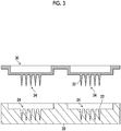
- the replication mold 30 having a protrusion-like pattern 34 consisting of needle-like protrusion portions 32 is prepared. It is preferable that the replication mold 30 be prepared by an electroforming process.
- the first mold 20 is processed to have conductivity.
- a metal for example, nickel
- the metal is deposited onto the first mold 20 by sputtering. In this way, the metal is attached to the surface of the first mold 20 and the needle-like recess portions 22.
- the first mold 20 processed to have conductivity is held in a cathode.
- Metal pellets are held in a metal case and used as an anode.
- the cathode holding the first mold 20 and the anode holding the metal pellets are immersed in an electroforming solution, and electric currents are applied thereto, so that the metal is embedded in the needle-like recess portions 22 of the first mold 20.
- the metal is peeled off, thereby preparing the replication mold 30 having protrusion-like pattern 34.
- the electroforming process is not the only way of preparing the replication mold 30 having the protrusion-like pattern 34.
- the replication mold 30 can also be prepared by a method of supplying a resin to the first mold 20 and curing the resin. By dispersing metal particles in the supplied resin, the metal can be incorporated into the replication mold 30.
- the steps shown in Figs. 1 to 3 are not the only way of preparing the replication mold 30 having the protrusion-like pattern 34.
- a mold large-sized master which is prepared by the same method as the method used for preparing the master 10 and in which a plurality of protrusion-like patterns is formed.
- it costs more to prepare a master having a finer and more complicated pattern shape. Therefore, preparing a large-sized master costs a lot of money.
- the needle-like protrusion portions may have different shapes. Therefore, in a case where the first mold 20 having a plurality of recess-like patterns is prepared from the master 10 by imprinting as shown in Figs. 1 to 3 , it is possible to prepare the mold with low costs.
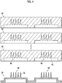
- a mold sheet 40 is manufactured using the replication mold 30.
- the mold sheet 40 can be manufactured by pouring a medical grade silicone material (for example, MDX4-4210 manufactured by Dow Corning) into the replication mold 30, heating the mold at 150°C so that the material is cured, and then peeling off the mold sheet 40 from the replication mold 30.
- the mold sheet 40 can also be manufactured by a method of pouring a UV curable resin which is cured by being irradiating with ultraviolet rays into the replication mold 30, irradiating the resin with ultraviolet rays in a nitrogen atmosphere, and then peeling off the mold sheet 40 from the replication mold 30.
- the mold sheet 40 can also be manufactured by a method of pouring a solution obtained by dissolving plastic resins such as polystyrene and polymethylmethacrylate (PMMA) in an organic solvent into the replication mold 30 coated with a release agent, drying the solution so that the organic solvent is volatilized and the resins are cured, and then peeling off the mold sheet 40 from the replication mold 30.
- the formed protrusion-like pattern 34 of the replication mold 30 corresponds to a recess-like pattern 44 of the mold sheet 40.
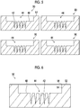
- the mold sheet 40 is cut for each recess-like pattern 44 formed of needle-like recess portions 42, thereby manufacturing a mold 50.
- the mold 50 can be formed which is in the form of an inverted master 10 and has an array of a plurality of needle-like recess portions 42.
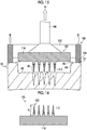
- the mold 50 is prepared as shown in Fig. 6 .
- a drug solution is supplied to the needle-like recess portions 42 and dried, thereby forming a drug layer 110 in which the needle-like recess portions 42 contain the drug.
- a region 48 where the needle-like recess portions 42 are formed is coated with a drug solution containing a drug.
- the coating method is not particularly limited.
- the drug solution can be supplied from a nozzle.
- a drop dispensing method may also be used.
- the drug solution can be aspirated from the back surface of the mold 50. In this way, it is possible to facilitate the filling of the needle-like recess portions 42 with the drug solution.
- the drug solution is dried to form the drug layer 110.
- the drying rate is optimized by controlling the temperature and humidity conditions, it is possible to suppress the drug solution from sticking to the wall surface of the needle-like recess portions 42 and to cause the drug solution to dry while gathering at the tip of the needle-like recess portions 42.
- the drug solution is solidified and can contract further than the drug solution with which the needle-like recess portions 42 are filled.
- the drug layer 110 can be easily peeled off from the needle-like recess portions 42.
- a polymer layer forming solution 112 is supplied onto the drug layer 110 containing a predetermined amount of drug, so that the polymer layer forming solution 112 is supplied to the needle-like recess portions 42 and onto the region 48 where the needle-like recess portions 42 are formed.
- the polymer layer forming solution 112 is a polymer solution forming a polymer layer 114.
- the method of supplying the polymer layer forming solution 112 is not limited to these.
- the drug layer 110 is solidified by drying. Therefore, it is possible to inhibit the drug contained in the drug layer 110 from diffusing into the polymer layer forming solution 112.
- the polymer layer forming solution 112 is supplied by a supply unit 90, covers at least a part of a step portion 52 provided around the region 48 where the needle-like recess portions 42 are formed, and flows over a contact position 56 from the side of the region 48 where the needle-like recess portions 42 are formed.
- the supplied polymer layer forming solution 112 is repelled by the mold 50 and contracts due to surface tension. As shown in Fig.
- the contracted polymer layer forming solution 112 is fixed (pinned) to the contact position 56 which is a point of contact between the step portion 52 of the mold 50 and a wall portion 54 extending to the step portion 52 from the region 48 where the needle-like recess portions 42 are formed.
- the polymer layer forming solution 112 is dried in a state of being fixed to the contact position 56, the polymer layer 114 of the transdermal absorption sheet can be stably shaped.
- the polymer layer forming solution 112 may be aspirated from a side of the mold 50 that is opposite to the region 48 where the needle-like recess portions 42 are formed.
- the needle-like recess portions 42 can be filled with the polymer layer forming solution 112.
- the polymer layer forming solution 112 has bubbles, it is possible to remove the bubbles by the aspiration.
- the polymer layer forming solution 112 After being supplied to the mold 50, the polymer layer forming solution 112 is dried and solidified. In this way, the polymer layer 114 can be formed on the drug layer 110 as shown in Fig. 10 , and the transdermal absorption sheet 120 having the drug layer 110 and the polymer layer 114 can be manufactured.
- the drying of the polymer layer forming solution 112 may be started in a state where the polymer layer forming solution 112 is fixed to the contact position 56 or in a state where the polymer layer forming solution 112 remains on the step portion 52. In a case where the drying is started in a state where the polymer layer forming solution 112 remains on the step portion 52, the polymer layer forming solution 112 on the step portion 52 is effectively rapidly dried. By the drying of the polymer layer forming solution 112 on the step portion 52, the polymer layer forming solution 112 can be fixed to the contact position 56.
- the volume of the polymer layer forming solution 112 is reduced.
- the volume is reduced in the film thickness direction of the sheet, which leads to the reduction in the film thickness.
- the amount of water in the transdermal absorption sheet 120 after drying and the like are appropriately set. In a case where the amount of water in the polymer layer 114 is excessively reduced by drying, it is difficult to peel off the transdermal absorption sheet. Therefore, it is preferable to set the amount of water such that the transdermal absorption sheet retains elastic force.
- Fig. 11 is a perspective view of a pressing jig used for applying pressing force to the step portion 52.
- Fig. 12 is a plan view of the mold 50.
- the pressing jig 150 shown in Fig. 11 is composed of a base portion 152 in the form of a hollow tube and claw portions 154 provided on the base portion 152.
- Fig. 13 is a view showing a state where the pressing jig is placed on the step portion, and pressing force is applied thereto. To apply the pressing force to the step portion 52, the pressing jig 150 is placed such that the claw portions 154 come into contact with the step portion 52.
- the claw portions 154 are on the upper side. However, the pressing jig 150 is inverted during use. As shown in Fig.
- the mold 50 is in the form of a circle, and the step portion 52 is also in the form of a circle.
- the pressing jig 150 By pressing the pressing jig 150, it is possible to apply pressing force to the step portion 52 at the position where the claw portions 154 come into contact with the step portion 52.
- the pressing jig 150 By causing the pressing jig 150 to penetrate the base portion 152, it is possible to enable a vacuum suction pad 160 to pass through the base portion 152 in the process of aspirating the transdermal absorption sheet by the vacuum suction pad. In this way, the back surface side (opposite side of the mold 50) of the transdermal absorption sheet 120 can be aspirated by the vacuum suction pad 160.
- the shape of the pressing jig 150 is not limited to the shape shown in Fig. 11 .
- the shape of the pressing jig 150 is not particularly limited, as long as the jig 150 can press a part of the step portion 52, and the transdermal absorption sheet 120 can be aspirated from the back surface side thereof by the vacuum suction pad 160.
- the number of claw portions 154 is not limited to two as shown in Fig. 11 , and a pressing jig having three or more claw portions can be used. However, the larger the number of claw portions 154 is, the less the mold 50 is deformed in a case where pressing force is applied to the step portion 52 by the pressing jig 150, and the harder it is to peel off the transdermal absorption sheet 120.
- the increase in the number of claw portions 154 is not preferable.
- the pressing jig 150 can have one claw portion.
- the number of claw portions 154 is the number of positions at which the step portion 52 is pressed.
- the positions to which the pressing force is to be applied be arranged at equal intervals. In a case where the positions are arranged at equal intervals, the mold 50 can be evenly deformed, and the transdermal absorption sheet can be easily peeled off.
- the proportion of the part to which pressing force is to be applied in the entire circumference of the step portion 52 is preferably equal to or lower than 75%, and more preferably equal to or lower than 50%. Furthermore, the proportion is preferably equal to or higher than 15%. In a case where the proportion of the part to which pressing force is to be applied is within the above range, it is possible to bend the mold 50 in the process of peeling off the transdermal absorption sheet. In addition, it is possible to prevent the mold 50 from being lifted up in the process of aspirating and peeling off the transdermal absorption sheet 120 by using the vacuum suction pad 160.
- vacuum suction pad 160 in order to inhibit the deformation of the transdermal absorption sheet 120 during suction (aspiration), it is preferable to use a flat pad.
- Fig. 14 is a view showing a state where peeling has been started using the vacuum suction pad 160.
- the end portion of the mold 50 is pressed in a second direction B.
- the transdermal absorption sheet 120 is aspirated by the vacuum suction pad 160 in a first direction A (a direction opposite to the second direction B) which is a direction perpendicular to the region 48 where the needle-like recess portions 42 are formed. Therefore, the central portion of the mold 50 is pulled by the transdermal absorption sheet 120. Therefore, as shown in Fig. 14 , the mold 50 is deformed from the side of the end portion (the side of the wall portion 54) of the region 48 where the needle-like recess portions 42 are formed. As a result, first, the end portion of the transdermal absorption sheet 120 starts to be peeled off from the side of the end portion of the region 48, where the needle-like recess portions 42 are formed, of the mold 50.
- the transdermal absorption sheet 120 is pulled up in the first direction A. Consequently, the central portion of the mold 50 is further pulled to the transdermal absorption sheet 120. Because the end portion of the mold 50 is pressed by pressing force, the mold 50 is bent. As a result, in the process of releasing and peeling off needle-like protrusion portions 122 of the transdermal absorption sheet 120 from the mold 50, it is possible to inhibit the damage of needle-like protrusion portions 122. Furthermore, by performing aspiration with the vacuum suction pad 160, it is possible to pull up only the transdermal absorption sheet 120 without pulling up the mold 50 together with the transdermal absorption sheet 120 ( Fig. 15 ).
- transdermal absorption sheet 120 can be peeled off by aspiration force equal to or higher than 50 kPa.
- the vacuum suction pad 160 is preferably a flat pad. In a case where a flat pad is used, the transdermal absorption sheet 120 can be aspirated in a flat state. Therefore, it is possible to inhibit the transdermal absorption sheet 120 from being deformed during peeling.
- Fig. 16 is a cross-sectional view showing an example of the transdermal absorption sheet 120 peeled off.
- the shape of the needle-like protrusion portions 122 of the transdermal absorption sheet 120 to be manufactured is not particularly limited as long as the portions 122 have a tapered tip.
- the needle-like protrusion portions 122 can be in the form of a cone or in the form of a pyramid such as a trigonal pyramid or a quadrangular pyramid.
- the needle-like protrusion portions 122 can be formed of a tapered needle portion and a frustum connected to the needle portion.
- a height H 1 of the needle-like protrusion portions 122 of the protrusion-like pattern is in the range of 100 ⁇ m or greater and 2,000 ⁇ m or less, preferably 200 ⁇ m or greater and 1,500 ⁇ m or less.
- the transdermal absorption sheet 120 having the needle-like protrusion portions 122 to be manufactured is a replica of the master 10 having the protrusion-like pattern 14. Therefore, by forming the protrusion-like pattern 14 of the master 10 into a desired shape, it is possible to manufacture the transdermal absorption sheet 120 having the needle-like protrusion portions 122 in a desired shape.
- the polymer layer forming solution which is a polymer resin solution used in the present embodiment will be described.
- the material of the resin polymer used in the polymer layer forming solution it is preferable to use a biocompatible resin.
- a resin it is preferable to use saccharides such as glucose, maltose, pullulan, chondroitin sulfate, sodium hyaluronate, and hydroxyethyl starch, proteins such as gelatin, and biodegradable polymers such as polylactic acid and a lactic acid/glycolic acid copolymer.
- saccharides such as glucose, maltose, pullulan, chondroitin sulfate, sodium hyaluronate, and hydroxyethyl starch
- proteins such as gelatin
- biodegradable polymers such as polylactic acid and a lactic acid/glycolic acid copolymer.
- gelatin-based materials exhibit adhesiveness to many substrates and have high gel strength as a gelling material.
- the gelatin-based materials can be suitably used.
- concentration of the resin polymer varies with the material, the concentration of the resin polymer contained in the polymer layer forming solution is preferably 10% to 50% by mass.
- solvent used for dissolution in addition to warm water, volatile solvents may also be used.
- solvent methyl ethyl ketone (MEK), an alcohol, and the like can be used.
- the polymer layer forming solution can be prepared by a method of dissolving water-soluble powder in water.
- heating may be performed to dissolve the polymer.
- the temperature can be appropriately selected according to the type of the polymer material, it is preferable to heat the polymer material at about a temperature equal to or lower than 60°C.
- the viscosity of the polymer layer forming solution is preferably equal to or lower than 2,000 Pa ⁇ s, and more preferably equal to or lower than 1,000 Pa ⁇ s.
- the polymer layer forming solution can be easily injected into the needle-like recess portions of the mold.
- the viscosity of the polymer layer forming solution can be measured, for example, by a capillary viscometer, a falling ball viscometer, a rotary viscometer, or a vibrating viscometer.
- the drug solution forming the drug layer 110 will be described.
- the drug solution is a solution containing a predetermined amount of a drug in the polymer layer forming solution. Whether or not the drug solution contains a predetermined amount of a drug is determined by whether or not the drug solution can exert efficacy in a case where the drug solution penetrates into the body surface. Therefore, containing a predetermined amount of a drug means that the drug solution contains a drug in such an amount that exerts efficacy in a case where the drug solution penetrates into the body surface.
- the drug to be incorporated into the drug solution is not limited as long as it functions as a drug. Particularly, it is preferable to select the drug from peptides, proteins, nucleic acids, polysaccharides, vaccines, pharmaceutical compounds belonging to water-soluble low molecular weight compounds, or cosmetic ingredients.
- the concentration of polymers contained in the drug solution (the concentration of polymers excluding a drug in a case where the drug is a polymer) is preferably 0% to 30% by mass. Furthermore, the viscosity of the drug solution is preferably equal to or lower than 100 Pa ⁇ s, and more preferably equal to or lower than 10 Pa ⁇ s.
- a circular silicone rubber mold made of SIL-5930 having a diameter of 20 mm and 121 needle-like recess portions was used.
- the step portion had a width of 2 mm, and the diameter of the inside of the step portion (diameter of a region where needle-like recess portions were formed) was 16 mm. Furthermore, the depth of the step portion (distance between the step portion and the region where the needle-like recess portions were formed) was 0.5 mm.
- a 40 wt% aqueous chondroitin sulfate (CS) solution 250 mg was added dropwise to the inside of the step portion of the mold and dried, thereby manufacturing a transdermal absorption sheet.
- the transdermal absorption sheet manufactured in the present example was prepared to check the release properties in the step of peeling off. Therefore, only the polymer layer forming solution was used to manufacture the transdermal absorption sheet, and no drug layer was formed.
- the moisture content in the manufactured transdermal absorption sheet was 18 wt%.
- the pressing jig shown in Fig. 12 was placed on the step portion on the outer periphery of the mold, and pressed on the mold so that pressing force was applied.
- the pressing jig had an outer diameter of 20 mm and an inner diameter of 18 mm, and included claw portions having a height of 2 mm. Furthermore, the claw portions each had a length of 5 mm in the circumferential direction, and were arranged on the circumference at equal intervals. In addition to the pressing jig shown in Fig. 11 having two claw portions, pressing jigs provided with 3 or 4 claw portions were also tested for release properties. In the pressing jigs provided with 3 or 4 claw portions, the claw portions each had a length of 5 mm in the circumferential direction and were arranged on the circumference at equal intervals.
- a transdermal absorption sheet was manufactured in the same manner as in the above example by using a 40 wt% aqueous chondroitin sulfate solution. The entire circumference of the step portion of the mold was pressed so that the mold was fixed to the mold installation surface. In this state, a vacuum suction pad was brought into contact with the back surface side of the transdermal absorption sheet, and the transdermal absorption sheet was pulled up with an aspiration force of 98 kPa. The release properties were evaluated based on the following standard.
- Example 1 Step portion pressing position Suction pad Vacuum aspiration force Evaluation of release properties
- Example 1 Two sites (each having width of about 5 mm) on circumference at equal intervals 50 to 60 kPa A
- Example 2 Three sites (each having width of about 5 mm) on circumference at equal intervals 50 to 60 kPa A
- Example 3 Four sites (each having width of about 5 mm) on circumference at equal intervals 50 to 60 kPa
- Comparative Example 1 Entire circumference 98 kPa C
- Example 1 in which pressing force was applied to the mold at 2 sites or 3 sites on the step portion, the transdermal absorption sheet could be peeled off without deforming the needle-like protrusion portions. Even in Example 3 in which pressing force was applied to the mold at 4 sites on the step portion, the manufactured transdermal absorption sheet had no problem for use.
- the mold can be deformed by pressing force by the application of the pressing force to a part of the circumference of the mold.
- the pressing force acts in a direction opposite to a direction in which the transdermal absorption sheet is peeled off from the mold, by performing aspiration with a vacuum suction pad, it is possible to bend the mold and to easily peel off the needle-like protrusion portions from the mold.
- transdermal absorption sheet by peeling the transdermal absorption sheet in the direction perpendicular to the region where the needle-like recess portions are formed, it is possible to manufacture a transdermal absorption sheet without damaging the needle-like protrusion portions of the transdermal absorption sheet.
Landscapes
- Engineering & Computer Science (AREA)
- Mechanical Engineering (AREA)
- Health & Medical Sciences (AREA)
- General Health & Medical Sciences (AREA)
- Veterinary Medicine (AREA)
- Biomedical Technology (AREA)
- Heart & Thoracic Surgery (AREA)
- Hematology (AREA)
- Life Sciences & Earth Sciences (AREA)
- Animal Behavior & Ethology (AREA)
- Medical Informatics (AREA)
- Public Health (AREA)
- Anesthesiology (AREA)
- Dermatology (AREA)
- Manufacturing & Machinery (AREA)
- Chemical & Material Sciences (AREA)
- Inorganic Chemistry (AREA)
- Robotics (AREA)
- Physics & Mathematics (AREA)
- Fluid Mechanics (AREA)
- Media Introduction/Drainage Providing Device (AREA)
- Moulds For Moulding Plastics Or The Like (AREA)
- Casting Or Compression Moulding Of Plastics Or The Like (AREA)
Abstract
Description
- The present invention relates to a method for manufacturing a transdermal absorption sheet, particularly, to a method for manufacturing a transdermal absorption sheet by shape transfer using a mold in which needle-like recess portions are formed.
- In recent years, a micro-needle array has been known as a novel dosage form capable of intradermally administering drugs such as insulin, vaccines, and human growth hormone (hGH) without pain. The micro-needle array is an array of biodegradable microneedles (also called fine needles) containing a drug. In a case where the micro-needle array is attached to the skin, the microneedles pierce and are absorbed into the skin, and hence the drug contained in the microneedles can be administered into the skin. The micro-needle array is also called a transdermal absorption sheet.
- In order to prepare a molded article having a fine protrusion-like pattern such as the aforementioned micro-needle array, from a master having a fine protrusion-like pattern, a resinous mold is formed which has the shape of the master inverted, and then the molded article is prepared from the mold. There is a demand for improving the productivity of the molded article having such a fine pattern, and various methods have been suggested to satisfy the demand.
- For example,
JP2009-241358A - In the method described in
JP2009-241358A - Furthermore, in view of the mass production of a transdermal absorption sheet, it is desired that the transdermal absorption sheet can be mechanically and automatically released from a mold.
- The present invention has been made in consideration of the above circumstances, and an object thereof is to provide a method for manufacturing a transdermal absorption sheet that inhibits needle-like protrusion portions and a transdermal absorption sheet from being damaged during peeling and makes it possible to manufacture a transdermal absorption sheet in a stable shape.
- In order to achieve the object of the present invention, the method for manufacturing a transdermal absorption sheet according to an aspect of the present invention has a step of filling needle-like recess portions of a mold, which comprises the needle-like recess portions and a step portion that is formed around a region where the needle-like recess portions are formed and is higher than the region, with a drug solution and drying the drug solution so as to form a drug layer, a step of supplying a polymer layer forming solution to the inside of the step portion, a step of drying the polymer layer forming solution so as to form a polymer layer and a transdermal absorption sheet, and a step of peeling off the transdermal absorption sheet from the mold, in which in the step of peeling off, pressing force is applied to a part of the step portion in a second direction opposite to a first direction in which the transdermal absorption sheet is released from the mold, and the transdermal absorption sheet is aspirated by a vacuum suction pad from a side opposite to the mold so that the transdermal absorption sheet is peeled off from the mold in the first direction.
- According to the method for manufacturing a transdermal absorption sheet according to the aspect of the present invention, in the process of peeling off the transdermal absorption sheet from the mold, pressing force is applied to a part of the step portion in the second direction opposite to the first direction in which the transdermal absorption sheet is released from the mold. In this state, the transdermal absorption sheet is aspirated in the first direction by a vacuum suction pad. As a result, the end portion of the mold is pushed in the second direction while the central portion thereof is pulled in the first direction, which enables the mold to bend. Because the pressing force is applied to a part of the step portion of the mold, the mold can be easily deformed. Accordingly, by aspirating the transdermal absorption sheet with a vacuum suction pad, it is possible to inhibit the damage of the needle-like protrusion portions and the deformation of the transdermal absorption sheet and to manufacture a transdermal absorption sheet in a stable shape.
-
-
Fig. 1 is a process chart showing a procedure for manufacturing a mold. -
Fig. 2 is a process chart showing the procedure for manufacturing a mold. -
Fig. 3 is a process chart showing the procedure for manufacturing a mold. -
Fig. 4 is a process chart showing the procedure for manufacturing a mold. -
Fig. 5 is a process chart showing the procedure for manufacturing a mold. -
Fig. 6 is a process chart showing a procedure for manufacturing a transdermal absorption sheet. -
Fig. 7 is a process chart showing the procedure for manufacturing a transdermal absorption sheet. -
Fig. 8 is a process chart showing the procedure for manufacturing a transdermal absorption sheet. -
Fig. 9 is a process chart showing the procedure for manufacturing a transdermal absorption sheet. -
Fig. 10 is a process chart showing the procedure for manufacturing a transdermal absorption sheet. -
Fig. 11 is a perspective view of a pressing jig. -
Fig. 12 is a plan view of a mold. -
Fig. 13 is a process chart showing a procedure for peeling off a transdermal absorption sheet. -
Fig. 14 is a process chart showing the procedure for peeling off a transdermal absorption sheet. -
Fig. 15 is a process chart showing the procedure for peeling off a transdermal absorption sheet. -
Fig. 16 is a diagram showing a transdermal absorption sheet peeled off. - Hereinafter, a method for manufacturing a transdermal absorption sheet according to an embodiment of the present invention will be described with reference to the attached drawings. In the present specification, "to" is used to show that the numerical values listed before and after "to" are the lower limit and the upper limit.
-
Figs. 1 to 5 are process charts showing the procedure of a method for manufacturing a mold. For manufacturing amold 50, by performing imprinting on a resin matrix, afirst mold 20 is formed from amaster 10. After thefirst mold 20 is formed, areplication mold 30 is formed by an electroforming process. Then, by using a resin film, from thereplication mold 30, amold sheet 40 is formed which is in the form of an invertedreplication mold 30 and includes needle-like recess portions 42. Finally, themold sheet 40 is punched and cut for each pattern, thereby forming themold 50. Hereinafter, each step will be described. - First, the
master 10 shown inFig. 1 is prepared, in which a protrusion-like pattern 14 consisting of an array of a plurality of needle-like protrusion portions 12 is formed. There is no particular limitation on the method for preparing themaster 10 in which the protrusion-like pattern 14 is formed. For example, by processing a metal substrate such as stainless steel by means of mechanical cutting using a cutting tool such as a ball end mill, the plurality of needle-like protrusion portions 12 can be formed on the surface of themaster 10. - As another method, a Si substrate is coated with a photoresist and then subjected to exposure and development. Then, the substrate is etched by reactive ion etching (RIE) or the like so that the needle-
like protrusion portions 12 are formed on the surface of themaster 10. In a case where etching such as RIE is performed to form the needle-like protrusion portions 12 on the surface of themaster 10, by obliquely etching the Si substrate in a state of rotating the substrate, it is possible to form the needle-like protrusion portions 12. - Thereafter, as shown in
Fig. 2 , by using themaster 10, afirst mold 20 having a recess-like pattern 24 consisting of a plurality of needle-like recess portions 22 is prepared by an imprinting method. As a method for preparing thefirst mold 20, a resin matrix composed of the material of thefirst mold 20 such as a thermoplastic resin is prepared. The heatedmaster 10 is pressed on the surface of the resin matrix, and the resin matrix is cured by cooling or the like, thereby forming the needle-like recess portions 22 on the surface of the resin matrix. Subsequently, themaster 10 is peeled off from the resin matrix, and the resin matrix is molded as necessary. In this way, thefirst mold 20 can be manufactured.Fig. 2 shows the procedure of forming two recess-like patterns 24 having the needle-like recess portions 22 by using themaster 10. However, the number of recess-like patterns is not limited. A first mold in which three or more recess-like patterns are formed may be manufactured. - Thereafter, as shown in
Fig. 3 , by using thefirst mold 20, thereplication mold 30 having a protrusion-like pattern 34 consisting of needle-like protrusion portions 32 is prepared. It is preferable that thereplication mold 30 be prepared by an electroforming process. - In the electroforming process, first, the
first mold 20 is processed to have conductivity. A metal (for example, nickel) is deposited onto thefirst mold 20 by sputtering. In this way, the metal is attached to the surface of thefirst mold 20 and the needle-like recess portions 22. - Then, the
first mold 20 processed to have conductivity is held in a cathode. Metal pellets are held in a metal case and used as an anode. The cathode holding thefirst mold 20 and the anode holding the metal pellets are immersed in an electroforming solution, and electric currents are applied thereto, so that the metal is embedded in the needle-like recess portions 22 of thefirst mold 20. Then, the metal is peeled off, thereby preparing thereplication mold 30 having protrusion-like pattern 34. - The electroforming process is not the only way of preparing the
replication mold 30 having the protrusion-like pattern 34. Thereplication mold 30 can also be prepared by a method of supplying a resin to thefirst mold 20 and curing the resin. By dispersing metal particles in the supplied resin, the metal can be incorporated into thereplication mold 30. - The steps shown in
Figs. 1 to 3 are not the only way of preparing thereplication mold 30 having the protrusion-like pattern 34. For preparing thereplication mold 30, it is also possible to use a mold (large-sized master) which is prepared by the same method as the method used for preparing themaster 10 and in which a plurality of protrusion-like patterns is formed. However, it costs more to prepare a master having a finer and more complicated pattern shape. Therefore, preparing a large-sized master costs a lot of money. Furthermore, there is a concern that the needle-like protrusion portions may have different shapes. Therefore, in a case where thefirst mold 20 having a plurality of recess-like patterns is prepared from themaster 10 by imprinting as shown inFigs. 1 to 3 , it is possible to prepare the mold with low costs. - Then, as shown in
Fig. 4 , amold sheet 40 is manufactured using thereplication mold 30. Themold sheet 40 can be manufactured by pouring a medical grade silicone material (for example, MDX4-4210 manufactured by Dow Corning) into thereplication mold 30, heating the mold at 150°C so that the material is cured, and then peeling off themold sheet 40 from thereplication mold 30. In addition, themold sheet 40 can also be manufactured by a method of pouring a UV curable resin which is cured by being irradiating with ultraviolet rays into thereplication mold 30, irradiating the resin with ultraviolet rays in a nitrogen atmosphere, and then peeling off themold sheet 40 from thereplication mold 30. Furthermore, themold sheet 40 can also be manufactured by a method of pouring a solution obtained by dissolving plastic resins such as polystyrene and polymethylmethacrylate (PMMA) in an organic solvent into thereplication mold 30 coated with a release agent, drying the solution so that the organic solvent is volatilized and the resins are cured, and then peeling off themold sheet 40 from thereplication mold 30. The formed protrusion-like pattern 34 of thereplication mold 30 corresponds to a recess-like pattern 44 of themold sheet 40. - Thereafter, as shown in
Fig. 5 , themold sheet 40 is cut for each recess-like pattern 44 formed of needle-like recess portions 42, thereby manufacturing amold 50. In this way, themold 50 can be formed which is in the form of aninverted master 10 and has an array of a plurality of needle-like recess portions 42. - Next, a method of manufacturing a transdermal absorption sheet using the
mold 50 manufactured by the above manufacturing method will be described. - First, the
mold 50 is prepared as shown inFig. 6 . Then, as shown inFig. 7 , a drug solution is supplied to the needle-like recess portions 42 and dried, thereby forming adrug layer 110 in which the needle-like recess portions 42 contain the drug. To form thedrug layer 110, aregion 48 where the needle-like recess portions 42 are formed is coated with a drug solution containing a drug. The coating method is not particularly limited. For example, the drug solution can be supplied from a nozzle. Furthermore, a drop dispensing method may also be used. After being supplied, the drug solution can be aspirated from the back surface of themold 50. In this way, it is possible to facilitate the filling of the needle-like recess portions 42 with the drug solution. - After the needle-
like recess portions 42 are filled with the drug solution, the drug solution is dried to form thedrug layer 110. In drying the drug solution, in a case where the drying rate is optimized by controlling the temperature and humidity conditions, it is possible to suppress the drug solution from sticking to the wall surface of the needle-like recess portions 42 and to cause the drug solution to dry while gathering at the tip of the needle-like recess portions 42. - By the drying, the drug solution is solidified and can contract further than the drug solution with which the needle-
like recess portions 42 are filled. As a result, in the process of peeling off thetransdermal absorption sheet 120 from themold 50, thedrug layer 110 can be easily peeled off from the needle-like recess portions 42. - Then, as shown in
Fig. 8 , a polymerlayer forming solution 112 is supplied onto thedrug layer 110 containing a predetermined amount of drug, so that the polymerlayer forming solution 112 is supplied to the needle-like recess portions 42 and onto theregion 48 where the needle-like recess portions 42 are formed. The polymerlayer forming solution 112 is a polymer solution forming apolymer layer 114. To supply the polymerlayer forming solution 112, it is possible to use coating by a dispenser, bar coating or spin coating, coating by spray or the like, coating by drop dispensing, and the like. However, the method of supplying the polymerlayer forming solution 112 is not limited to these. Thedrug layer 110 is solidified by drying. Therefore, it is possible to inhibit the drug contained in thedrug layer 110 from diffusing into the polymerlayer forming solution 112. - During the supply of the polymer
layer forming solution 112, as shown inFig. 8 , the polymerlayer forming solution 112 is supplied by asupply unit 90, covers at least a part of astep portion 52 provided around theregion 48 where the needle-like recess portions 42 are formed, and flows over acontact position 56 from the side of theregion 48 where the needle-like recess portions 42 are formed. The supplied polymerlayer forming solution 112 is repelled by themold 50 and contracts due to surface tension. As shown inFig. 9 , the contracted polymerlayer forming solution 112 is fixed (pinned) to thecontact position 56 which is a point of contact between thestep portion 52 of themold 50 and awall portion 54 extending to thestep portion 52 from theregion 48 where the needle-like recess portions 42 are formed. In a case where the polymerlayer forming solution 112 is dried in a state of being fixed to thecontact position 56, thepolymer layer 114 of the transdermal absorption sheet can be stably shaped. Furthermore, before being dried, the polymerlayer forming solution 112 may be aspirated from a side of themold 50 that is opposite to theregion 48 where the needle-like recess portions 42 are formed. By performing the aspiration, the needle-like recess portions 42 can be filled with the polymerlayer forming solution 112. In addition, in a case where the polymerlayer forming solution 112 has bubbles, it is possible to remove the bubbles by the aspiration. - After being supplied to the
mold 50, the polymerlayer forming solution 112 is dried and solidified. In this way, thepolymer layer 114 can be formed on thedrug layer 110 as shown inFig. 10 , and thetransdermal absorption sheet 120 having thedrug layer 110 and thepolymer layer 114 can be manufactured. - The drying of the polymer
layer forming solution 112 may be started in a state where the polymerlayer forming solution 112 is fixed to thecontact position 56 or in a state where the polymerlayer forming solution 112 remains on thestep portion 52. In a case where the drying is started in a state where the polymerlayer forming solution 112 remains on thestep portion 52, the polymerlayer forming solution 112 on thestep portion 52 is effectively rapidly dried. By the drying of the polymerlayer forming solution 112 on thestep portion 52, the polymerlayer forming solution 112 can be fixed to thecontact position 56. - As the polymer
layer forming solution 112 dries, the volume of the polymerlayer forming solution 112 is reduced. In a case where the polymerlayer forming solution 112 is closely attached to themold 50 during the drying, the volume is reduced in the film thickness direction of the sheet, which leads to the reduction in the film thickness. - The amount of water in the
transdermal absorption sheet 120 after drying and the like are appropriately set. In a case where the amount of water in thepolymer layer 114 is excessively reduced by drying, it is difficult to peel off the transdermal absorption sheet. Therefore, it is preferable to set the amount of water such that the transdermal absorption sheet retains elastic force. - Then, the dried
transdermal absorption sheet 120 is peeled off from themold 50. In the process of peeling off thetransdermal absorption sheet 120 from themold 50, pressing force is applied to a part of thestep portion 52.Fig. 11 is a perspective view of a pressing jig used for applying pressing force to thestep portion 52.Fig. 12 is a plan view of themold 50. - The
pressing jig 150 shown inFig. 11 is composed of abase portion 152 in the form of a hollow tube and clawportions 154 provided on thebase portion 152.Fig. 13 is a view showing a state where the pressing jig is placed on the step portion, and pressing force is applied thereto. To apply the pressing force to thestep portion 52, thepressing jig 150 is placed such that theclaw portions 154 come into contact with thestep portion 52. InFig. 12 , for a clear view of theclaw portions 154 of thepressing jig 150, theclaw portions 154 are on the upper side. However, thepressing jig 150 is inverted during use. As shown inFig. 12 , themold 50 is in the form of a circle, and thestep portion 52 is also in the form of a circle. By pressing thepressing jig 150, it is possible to apply pressing force to thestep portion 52 at the position where theclaw portions 154 come into contact with thestep portion 52. By causing thepressing jig 150 to penetrate thebase portion 152, it is possible to enable avacuum suction pad 160 to pass through thebase portion 152 in the process of aspirating the transdermal absorption sheet by the vacuum suction pad. In this way, the back surface side (opposite side of the mold 50) of thetransdermal absorption sheet 120 can be aspirated by thevacuum suction pad 160. - The shape of the
pressing jig 150 is not limited to the shape shown inFig. 11 . The shape of thepressing jig 150 is not particularly limited, as long as thejig 150 can press a part of thestep portion 52, and thetransdermal absorption sheet 120 can be aspirated from the back surface side thereof by thevacuum suction pad 160. Furthermore, the number ofclaw portions 154 is not limited to two as shown inFig. 11 , and a pressing jig having three or more claw portions can be used. However, the larger the number ofclaw portions 154 is, the less themold 50 is deformed in a case where pressing force is applied to thestep portion 52 by thepressing jig 150, and the harder it is to peel off thetransdermal absorption sheet 120. Therefore, the increase in the number ofclaw portions 154 is not preferable. In addition, as long as themold 50 can be fixed to a surface in contact with the mold and is not lifted together with thetransdermal absorption sheet 120 in the process of releasing thetransdermal absorption sheet 120 from themold 50 by aspiration, thepressing jig 150 can have one claw portion. In the case of thepressing jig 150 shown inFig. 11 , the number ofclaw portions 154 is the number of positions at which thestep portion 52 is pressed. - In a case where pressing force is applied to a plurality of sites of the
step portion 52, it is preferable that the positions to which the pressing force is to be applied be arranged at equal intervals. In a case where the positions are arranged at equal intervals, themold 50 can be evenly deformed, and the transdermal absorption sheet can be easily peeled off. - In the
step portion 52, the proportion of the part to which pressing force is to be applied in the entire circumference of thestep portion 52 is preferably equal to or lower than 75%, and more preferably equal to or lower than 50%. Furthermore, the proportion is preferably equal to or higher than 15%. In a case where the proportion of the part to which pressing force is to be applied is within the above range, it is possible to bend themold 50 in the process of peeling off the transdermal absorption sheet. In addition, it is possible to prevent themold 50 from being lifted up in the process of aspirating and peeling off thetransdermal absorption sheet 120 by using thevacuum suction pad 160. - As the
vacuum suction pad 160, in order to inhibit the deformation of thetransdermal absorption sheet 120 during suction (aspiration), it is preferable to use a flat pad. -
Fig. 14 is a view showing a state where peeling has been started using thevacuum suction pad 160. By pressing force, the end portion of themold 50 is pressed in a second direction B. Furthermore, thetransdermal absorption sheet 120 is aspirated by thevacuum suction pad 160 in a first direction A (a direction opposite to the second direction B) which is a direction perpendicular to theregion 48 where the needle-like recess portions 42 are formed. Therefore, the central portion of themold 50 is pulled by thetransdermal absorption sheet 120. Therefore, as shown inFig. 14 , themold 50 is deformed from the side of the end portion (the side of the wall portion 54) of theregion 48 where the needle-like recess portions 42 are formed. As a result, first, the end portion of thetransdermal absorption sheet 120 starts to be peeled off from the side of the end portion of theregion 48, where the needle-like recess portions 42 are formed, of themold 50. - By the
vacuum suction pad 160, thetransdermal absorption sheet 120 is pulled up in the first direction A. Consequently, the central portion of themold 50 is further pulled to thetransdermal absorption sheet 120. Because the end portion of themold 50 is pressed by pressing force, themold 50 is bent. As a result, in the process of releasing and peeling off needle-like protrusion portions 122 of thetransdermal absorption sheet 120 from themold 50, it is possible to inhibit the damage of needle-like protrusion portions 122. Furthermore, by performing aspiration with thevacuum suction pad 160, it is possible to pull up only thetransdermal absorption sheet 120 without pulling up themold 50 together with the transdermal absorption sheet 120 (Fig. 15 ). In addition, by sufficiently bending themold 50, it is possible to peel off thetransdermal absorption sheet 120 from themold 50 with low aspiration force. Thetransdermal absorption sheet 120 can be peeled off by aspiration force equal to or higher than 50 kPa. - The
vacuum suction pad 160 is preferably a flat pad. In a case where a flat pad is used, thetransdermal absorption sheet 120 can be aspirated in a flat state. Therefore, it is possible to inhibit thetransdermal absorption sheet 120 from being deformed during peeling. -
Fig. 16 is a cross-sectional view showing an example of thetransdermal absorption sheet 120 peeled off. The shape of the needle-like protrusion portions 122 of thetransdermal absorption sheet 120 to be manufactured is not particularly limited as long as theportions 122 have a tapered tip. For example, the needle-like protrusion portions 122 can be in the form of a cone or in the form of a pyramid such as a trigonal pyramid or a quadrangular pyramid. Furthermore, the needle-like protrusion portions 122 can be formed of a tapered needle portion and a frustum connected to the needle portion. - A height H1 of the needle-
like protrusion portions 122 of the protrusion-like pattern is in the range of 100 µm or greater and 2,000 µm or less, preferably 200 µm or greater and 1,500 µm or less. - The
transdermal absorption sheet 120 having the needle-like protrusion portions 122 to be manufactured is a replica of themaster 10 having the protrusion-like pattern 14. Therefore, by forming the protrusion-like pattern 14 of themaster 10 into a desired shape, it is possible to manufacture thetransdermal absorption sheet 120 having the needle-like protrusion portions 122 in a desired shape. - The polymer layer forming solution which is a polymer resin solution used in the present embodiment will be described.
- As the material of the resin polymer used in the polymer layer forming solution, it is preferable to use a biocompatible resin. As such a resin, it is preferable to use saccharides such as glucose, maltose, pullulan, chondroitin sulfate, sodium hyaluronate, and hydroxyethyl starch, proteins such as gelatin, and biodegradable polymers such as polylactic acid and a lactic acid/glycolic acid copolymer. Among these, gelatin-based materials exhibit adhesiveness to many substrates and have high gel strength as a gelling material. Therefore, these materials enable the transdermal absorption sheet to be closely attached to the substrate in the process of peeling the transdermal absorption sheet from a mold, and make it easy to peel off the transdermal absorption sheet from the mold by using the substrate. Accordingly, the gelatin-based materials can be suitably used. Although the concentration of the resin polymer varies with the material, the concentration of the resin polymer contained in the polymer layer forming solution is preferably 10% to 50% by mass. As the solvent used for dissolution, in addition to warm water, volatile solvents may also be used. As the solvent, methyl ethyl ketone (MEK), an alcohol, and the like can be used.
- In a case where a water-soluble polymer (such as gelatin) is used, the polymer layer forming solution can be prepared by a method of dissolving water-soluble powder in water. In a case where the polymer material is not easily dissolved in water, heating may be performed to dissolve the polymer. Although the temperature can be appropriately selected according to the type of the polymer material, it is preferable to heat the polymer material at about a temperature equal to or lower than 60°C. The viscosity of the polymer layer forming solution is preferably equal to or lower than 2,000 Pa·s, and more preferably equal to or lower than 1,000 Pa·s. By appropriately adjusting the viscosity of the polymer layer forming solution, the polymer layer forming solution can be easily injected into the needle-like recess portions of the mold. The viscosity of the polymer layer forming solution can be measured, for example, by a capillary viscometer, a falling ball viscometer, a rotary viscometer, or a vibrating viscometer.
- The drug solution forming the
drug layer 110 will be described. The drug solution is a solution containing a predetermined amount of a drug in the polymer layer forming solution. Whether or not the drug solution contains a predetermined amount of a drug is determined by whether or not the drug solution can exert efficacy in a case where the drug solution penetrates into the body surface. Therefore, containing a predetermined amount of a drug means that the drug solution contains a drug in such an amount that exerts efficacy in a case where the drug solution penetrates into the body surface. - The drug to be incorporated into the drug solution is not limited as long as it functions as a drug. Particularly, it is preferable to select the drug from peptides, proteins, nucleic acids, polysaccharides, vaccines, pharmaceutical compounds belonging to water-soluble low molecular weight compounds, or cosmetic ingredients.
- The concentration of polymers contained in the drug solution (the concentration of polymers excluding a drug in a case where the drug is a polymer) is preferably 0% to 30% by mass. Furthermore, the viscosity of the drug solution is preferably equal to or lower than 100 Pa·s, and more preferably equal to or lower than 10 Pa·s.
- Hereinafter, the present invention will be more specifically described with reference to examples of the present invention. The materials, the amount of the materials used, the proportion of the materials, the details of treatments, the treatment procedures, and the like that will be described in the following examples can be appropriately modified as long as the gist of the present invention is maintained. Therefore, the scope of the present invention is not limited to the following specific examples.
- As a mold, a circular silicone rubber mold (made of SIL-5930) having a diameter of 20 mm and 121 needle-like recess portions was used. The step portion had a width of 2 mm, and the diameter of the inside of the step portion (diameter of a region where needle-like recess portions were formed) was 16 mm. Furthermore, the depth of the step portion (distance between the step portion and the region where the needle-like recess portions were formed) was 0.5 mm.
- A 40 wt% aqueous chondroitin sulfate (CS) solution (250 mg) was added dropwise to the inside of the step portion of the mold and dried, thereby manufacturing a transdermal absorption sheet. The transdermal absorption sheet manufactured in the present example was prepared to check the release properties in the step of peeling off. Therefore, only the polymer layer forming solution was used to manufacture the transdermal absorption sheet, and no drug layer was formed. The moisture content in the manufactured transdermal absorption sheet was 18 wt%. The pressing jig shown in
Fig. 12 was placed on the step portion on the outer periphery of the mold, and pressed on the mold so that pressing force was applied. The pressing jig had an outer diameter of 20 mm and an inner diameter of 18 mm, and included claw portions having a height of 2 mm. Furthermore, the claw portions each had a length of 5 mm in the circumferential direction, and were arranged on the circumference at equal intervals. In addition to the pressing jig shown inFig. 11 having two claw portions, pressing jigs provided with 3 or 4 claw portions were also tested for release properties. In the pressing jigs provided with 3 or 4 claw portions, the claw portions each had a length of 5 mm in the circumferential direction and were arranged on the circumference at equal intervals. In a state where the pressing force was being applied to the mold by the pressing jig, a vacuum suction pad (flat pad) was brought into contact with the back surface side of the transdermal absorption sheet, and the transdermal absorption sheet was pulled up with an aspiration force of 50 to 60 kPa. - As a comparative example, a transdermal absorption sheet was manufactured in the same manner as in the above example by using a 40 wt% aqueous chondroitin sulfate solution. The entire circumference of the step portion of the mold was pressed so that the mold was fixed to the mold installation surface. In this state, a vacuum suction pad was brought into contact with the back surface side of the transdermal absorption sheet, and the transdermal absorption sheet was pulled up with an aspiration force of 98 kPa. The release properties were evaluated based on the following standard.
- A: The transdermal absorption sheet could be peeled off from the mold without damaging the needle-like protrusion portions.
- B: Although the needle-like protrusion portions were damaged during peeling, the damage was unproblematic for the transdermal absorption sheet to be used.
- C: The transdermal absorption sheet could not be peeled off.
- The results are shown in Table 1.
[Table 1] Step portion pressing position Suction pad Vacuum aspiration force Evaluation of release properties Example 1 Two sites (each having width of about 5 mm) on circumference at equal intervals 50 to 60 kPa A Example 2 Three sites (each having width of about 5 mm) on circumference at equal intervals 50 to 60 kPa A Example 3 Four sites (each having width of about 5 mm) on circumference at equal intervals 50 to 60 kPa B Comparative Example 1 Entire circumference 98 kPa C - In Examples 1 and 2 in which pressing force was applied to the mold at 2 sites or 3 sites on the step portion, the transdermal absorption sheet could be peeled off without deforming the needle-like protrusion portions. Even in Example 3 in which pressing force was applied to the mold at 4 sites on the step portion, the manufactured transdermal absorption sheet had no problem for use.
- In Comparative Example 1 in which the entire circumference of the step portion of the mold was pressed to apply pressing force, the mold was not deformed. Furthermore, even though the transdermal absorption sheet was aspirated with an aspiration force higher than the aspiration force in Examples 1 to 3, and the vacuum suction pad was pulled up, the transdermal absorption sheet could not be peeled off. In the present example, the transdermal absorption sheet could be peeled off with an aspiration force lower than the aspiration force in the comparative example.
- According to the method for manufacturing a transdermal absorption sheet of an embodiment of the present invention, even though pressing force is not applied to the entire circumference of a mold, the mold can be deformed by pressing force by the application of the pressing force to a part of the circumference of the mold. In addition, because the pressing force acts in a direction opposite to a direction in which the transdermal absorption sheet is peeled off from the mold, by performing aspiration with a vacuum suction pad, it is possible to bend the mold and to easily peel off the needle-like protrusion portions from the mold. Therefore, by peeling the transdermal absorption sheet in the direction perpendicular to the region where the needle-like recess portions are formed, it is possible to manufacture a transdermal absorption sheet without damaging the needle-like protrusion portions of the transdermal absorption sheet.
-
- 10: master
- 12, 32: needle-like protrusion portion
- 14, 34: protrusion-like pattern
- 20: first mold
- 22, 42: needle-like recess portions
- 24, 44: recess-like pattern
- 30: replication mold
- 40: mold sheet
- 48: region where needle-like recess portions are formed
- 50: mold
- 52: step portion
- 54: wall portion
- 56: contact position
- 90: supply unit
- 110: drug layer
- 112: polymer layer forming solution
- 114: polymer layer
- 120: transdermal absorption sheet
- 122: needle-like protrusion portion
- 150: pressing jig
- 152: base portion
- 154: claw portion
- 160: vacuum suction pad
- A: first direction
- B: second direction
Claims (8)
- A method for manufacturing a transdermal absorption sheet, comprising:a step of filling needle-like recess portions of a mold, which includes the needle-like recess portions and a step portion that is formed around a region where the needle-like recess portions are formed and is higher than the region, with a drug solution and drying the drug solution so as to form a drug layer;a step of supplying a polymer layer forming solution to the inside of the step portion;a step of drying the polymer layer forming solution so as to form a polymer layer and a transdermal absorption sheet; anda step of peeling off the transdermal absorption sheet from the mold,wherein in the step of peeling off, pressing force is applied to a part of the step portion in a second direction opposite to a first direction in which the transdermal absorption sheet is released from the mold, and the transdermal absorption sheet is aspirated by a vacuum suction pad from a side opposite to the mold so that the transdermal absorption sheet is peeled off from the mold in the first direction.
- The method for manufacturing a transdermal absorption sheet according to claim 1,
wherein the vacuum suction pad is a flat pad. - The method for manufacturing a transdermal absorption sheet according to claim 1 or 2,
wherein the pressing force is applied using a pressing jig including a tubular base portion and claw portions connected to the base portion by bringing the claw portions into contact with the step portion. - The method for manufacturing a transdermal absorption sheet according to any one of claims 1 to 3,
wherein in the entire circumference of the step portion of the mold, a proportion of the part to which the pressing force is applied is equal to or lower than 75%. - The method for manufacturing a transdermal absorption sheet according to any one of claims 1 to 4,
wherein the pressing force is applied to the entire circumference of the step portion at equal intervals. - The method for manufacturing a transdermal absorption sheet according to any one of claims 1 to 5,
wherein in a case where a point of contact between the step portion and a wall portion extending to the step portion from the region where the needle-like recess portions are formed is regarded as a contact position, in the step of supplying the polymer layer forming solution, the polymer layer forming solution is supplied so that the solution flows over the contact position from the region where the needle-like recess portions are formed and is then fixed to the contact position while being contracted. - The method for manufacturing a transdermal absorption sheet according to any one of claims 1 to 6,
wherein the first direction is a direction perpendicular to the region where the needle-like recess portions are formed. - The method for manufacturing a transdermal absorption sheet according to any one of claims 1 to 7,
wherein an aspiration force of the vacuum suction pad is equal to or higher than 50 kPa.
Applications Claiming Priority (2)
| Application Number | Priority Date | Filing Date | Title |
|---|---|---|---|
| JP2018180246 | 2018-09-26 | ||
| PCT/JP2019/037478 WO2020067101A1 (en) | 2018-09-26 | 2019-09-25 | Method of manufacturing transdermal absorption sheet |
Publications (3)
| Publication Number | Publication Date |
|---|---|
| EP3858417A1 true EP3858417A1 (en) | 2021-08-04 |
| EP3858417A4 EP3858417A4 (en) | 2021-11-24 |
| EP3858417B1 EP3858417B1 (en) | 2022-12-21 |
Family
ID=69949880
Family Applications (1)
| Application Number | Title | Priority Date | Filing Date |
|---|---|---|---|
| EP19867027.5A Active EP3858417B1 (en) | 2018-09-26 | 2019-09-25 | Method of manufacturing transdermal absorption sheet |
Country Status (5)
| Country | Link |
|---|---|
| US (1) | US11160965B2 (en) |
| EP (1) | EP3858417B1 (en) |
| JP (1) | JP7008144B2 (en) |
| CN (1) | CN112839698B (en) |
| WO (1) | WO2020067101A1 (en) |
Families Citing this family (3)
| Publication number | Priority date | Publication date | Assignee | Title |
|---|---|---|---|---|
| US12421638B2 (en) * | 2019-02-28 | 2025-09-23 | Velcro Ip Holdings Llc | Making soft fabric touch fasteners |
| CN112569465B (en) * | 2020-12-29 | 2022-07-19 | 华东理工大学 | A kind of preparation method of microneedle patch |
| CN118105610A (en) * | 2022-11-30 | 2024-05-31 | 苏州悦肤达医疗科技有限公司 | Microneedle patch, preparation mold and preparation method of microneedle patch |
Family Cites Families (10)
| Publication number | Priority date | Publication date | Assignee | Title |
|---|---|---|---|---|
| JP2009241358A (en) | 2008-03-31 | 2009-10-22 | Fujifilm Corp | Method for producing needle sheet |
| JP2009241357A (en) * | 2008-03-31 | 2009-10-22 | Fujifilm Corp | Method for producing functional sheet |
| JP5363165B2 (en) | 2009-03-31 | 2013-12-11 | 富士フイルム株式会社 | Method and apparatus for forming fine uneven pattern |
| JP6411395B2 (en) | 2015-03-10 | 2018-10-24 | 富士フイルム株式会社 | Method for producing transdermal absorption sheet |
| JP6499598B2 (en) * | 2015-10-06 | 2019-04-10 | 富士フイルム株式会社 | Method for producing transdermal absorption sheet |
| JP6531052B2 (en) * | 2016-03-07 | 2019-06-12 | 富士フイルム株式会社 | Method of manufacturing reverse mold, method of manufacturing functional sheet, and peeling apparatus |
| JP6736337B2 (en) * | 2016-04-15 | 2020-08-05 | 富士フイルム株式会社 | Micro needle array |
| JP2018015322A (en) * | 2016-07-28 | 2018-02-01 | 富士フイルム株式会社 | Method for producing transdermal absorption sheet |
| CN106905545A (en) * | 2017-01-10 | 2017-06-30 | 罗穗 | The preparation method of cross-linked hyaluronic acid gel, needle adhesive film and needle adhesive film |
| TWI633901B (en) * | 2017-05-16 | 2018-09-01 | 怡定興科技股份有限公司 | Medical beauty microneedle patch manufacturing method |
-
2019
- 2019-09-25 JP JP2020549258A patent/JP7008144B2/en active Active
- 2019-09-25 CN CN201980063393.1A patent/CN112839698B/en active Active
- 2019-09-25 EP EP19867027.5A patent/EP3858417B1/en active Active
- 2019-09-25 WO PCT/JP2019/037478 patent/WO2020067101A1/en not_active Ceased
-
2021
- 2021-03-16 US US17/202,360 patent/US11160965B2/en not_active Expired - Fee Related
Also Published As
| Publication number | Publication date |
|---|---|
| CN112839698A (en) | 2021-05-25 |
| JP7008144B2 (en) | 2022-01-25 |
| CN112839698B (en) | 2022-03-22 |
| EP3858417A4 (en) | 2021-11-24 |
| EP3858417B1 (en) | 2022-12-21 |
| US11160965B2 (en) | 2021-11-02 |
| JPWO2020067101A1 (en) | 2021-09-02 |
| WO2020067101A1 (en) | 2020-04-02 |
| US20210196938A1 (en) | 2021-07-01 |
Similar Documents
| Publication | Publication Date | Title |
|---|---|---|
| US11160965B2 (en) | Method for manufacturing transdermal absorption sheet | |
| CN104780967B (en) | Method for manufacturing transdermal-absorption sheet | |
| KR102139335B1 (en) | Method and Apparatus for Manufacturing Microneedle Containing Coatings on Needle Tip | |
| CN111603435B (en) | Soluble microneedle and preparation method thereof | |
| US20180250851A1 (en) | Manufacturing method of pattern sheet | |
| EP3466478B1 (en) | Microneedle array | |
| JP2013153866A (en) | Transdermal absorption sheet and method for manufacturing transdermal absorption sheet | |
| US10596361B2 (en) | Transdermal absorption sheet and method of producing the same | |
| EP3153290B1 (en) | Method of manufacturing mold and method of manufacturing pattern sheet | |
| JP2009082206A (en) | Method for producing functional membrane | |
| WO2017056894A1 (en) | Mould fabrication method, patterned sheet production method, electroformed mould fabrication method, and mould fabrication method using electroformed mould | |
| US10870223B2 (en) | Method of manufacturing needle-like array sheet | |
| CN108478520A (en) | A kind of coating microneedle array and preparation method thereof accurately controlling drugloading rate | |
| EP3153291B1 (en) | Method of manufacturing mold and method of manufacturing pattern sheet | |
| EP3278834B1 (en) | Method of producing transdermal absorption sheet | |
| JP7405471B2 (en) | Particle-attached microneedles and their manufacturing method | |
| JP6635876B2 (en) | Concave pattern mold, method for producing concave pattern mold, and method for producing pattern sheet | |
| JP2010069242A (en) | Microneedle sheet and method for manufacturing the same | |
| WO2020067102A1 (en) | Mold, and method for producing transdermal absorption sheet | |
| JP2009083125A (en) | Method and apparatus for producing functional film | |
| CN116920260A (en) | Method for accurately controlling coating height and easily preparing coated microneedles in batches | |
| CN116920258A (en) | Microneedle and preparation method thereof |
Legal Events
| Date | Code | Title | Description |
|---|---|---|---|
| STAA | Information on the status of an ep patent application or granted ep patent |
Free format text: STATUS: THE INTERNATIONAL PUBLICATION HAS BEEN MADE |
|
| PUAI | Public reference made under article 153(3) epc to a published international application that has entered the european phase |
Free format text: ORIGINAL CODE: 0009012 |
|
| STAA | Information on the status of an ep patent application or granted ep patent |
Free format text: STATUS: REQUEST FOR EXAMINATION WAS MADE |
|
| 17P | Request for examination filed |
Effective date: 20210317 |
|
| AK | Designated contracting states |
Kind code of ref document: A1 Designated state(s): AL AT BE BG CH CY CZ DE DK EE ES FI FR GB GR HR HU IE IS IT LI LT LU LV MC MK MT NL NO PL PT RO RS SE SI SK SM TR |
|
| A4 | Supplementary search report drawn up and despatched |
Effective date: 20211022 |
|
| RIC1 | Information provided on ipc code assigned before grant |
Ipc: B29C 33/40 20060101ALI20211018BHEP Ipc: B29C 39/00 20060101ALI20211018BHEP Ipc: B29C 33/00 20060101ALI20211018BHEP Ipc: A61M 37/00 20060101ALI20211018BHEP Ipc: B29C 39/36 20060101AFI20211018BHEP |
|
| DAV | Request for validation of the european patent (deleted) | ||
| DAX | Request for extension of the european patent (deleted) | ||
| REG | Reference to a national code |
Ref country code: DE Ref legal event code: R079 Ref document number: 602019023528 Country of ref document: DE Free format text: PREVIOUS MAIN CLASS: A61M0037000000 Ipc: B29C0039360000 |
|
| GRAP | Despatch of communication of intention to grant a patent |
Free format text: ORIGINAL CODE: EPIDOSNIGR1 |
|
| STAA | Information on the status of an ep patent application or granted ep patent |
Free format text: STATUS: GRANT OF PATENT IS INTENDED |
|
| RIC1 | Information provided on ipc code assigned before grant |
Ipc: B29K 67/00 20060101ALN20220712BHEP Ipc: B29C 39/02 20060101ALN20220712BHEP Ipc: B29C 39/42 20060101ALN20220712BHEP Ipc: B29L 31/00 20060101ALN20220712BHEP Ipc: B29C 37/00 20060101ALI20220712BHEP Ipc: B29C 59/02 20060101ALI20220712BHEP Ipc: B29C 33/46 20060101ALI20220712BHEP Ipc: B29C 33/44 20060101ALI20220712BHEP Ipc: B29C 33/38 20060101ALI20220712BHEP Ipc: B29C 33/40 20060101ALI20220712BHEP Ipc: B29C 39/00 20060101ALI20220712BHEP Ipc: B29C 33/00 20060101ALI20220712BHEP Ipc: A61M 37/00 20060101ALI20220712BHEP Ipc: B29C 39/36 20060101AFI20220712BHEP |
|
| INTG | Intention to grant announced |
Effective date: 20220728 |
|
| GRAS | Grant fee paid |
Free format text: ORIGINAL CODE: EPIDOSNIGR3 |
|
| GRAA | (expected) grant |
Free format text: ORIGINAL CODE: 0009210 |
|
| STAA | Information on the status of an ep patent application or granted ep patent |
Free format text: STATUS: THE PATENT HAS BEEN GRANTED |
|
| AK | Designated contracting states |
Kind code of ref document: B1 Designated state(s): AL AT BE BG CH CY CZ DE DK EE ES FI FR GB GR HR HU IE IS IT LI LT LU LV MC MK MT NL NO PL PT RO RS SE SI SK SM TR |
|
| REG | Reference to a national code |
Ref country code: GB Ref legal event code: FG4D |
|
| REG | Reference to a national code |
Ref country code: CH Ref legal event code: EP |
|
| REG | Reference to a national code |
Ref country code: DE Ref legal event code: R096 Ref document number: 602019023528 Country of ref document: DE |
|
| REG | Reference to a national code |
Ref country code: AT Ref legal event code: REF Ref document number: 1538776 Country of ref document: AT Kind code of ref document: T Effective date: 20230115 |
|
| REG | Reference to a national code |
Ref country code: IE Ref legal event code: FG4D |
|
| REG | Reference to a national code |
Ref country code: LT Ref legal event code: MG9D |
|
| REG | Reference to a national code |
Ref country code: NL Ref legal event code: MP Effective date: 20221221 |
|
| PG25 | Lapsed in a contracting state [announced via postgrant information from national office to epo] |
Ref country code: SE Free format text: LAPSE BECAUSE OF FAILURE TO SUBMIT A TRANSLATION OF THE DESCRIPTION OR TO PAY THE FEE WITHIN THE PRESCRIBED TIME-LIMIT Effective date: 20221221 Ref country code: NO Free format text: LAPSE BECAUSE OF FAILURE TO SUBMIT A TRANSLATION OF THE DESCRIPTION OR TO PAY THE FEE WITHIN THE PRESCRIBED TIME-LIMIT Effective date: 20230321 Ref country code: LT Free format text: LAPSE BECAUSE OF FAILURE TO SUBMIT A TRANSLATION OF THE DESCRIPTION OR TO PAY THE FEE WITHIN THE PRESCRIBED TIME-LIMIT Effective date: 20221221 Ref country code: FI Free format text: LAPSE BECAUSE OF FAILURE TO SUBMIT A TRANSLATION OF THE DESCRIPTION OR TO PAY THE FEE WITHIN THE PRESCRIBED TIME-LIMIT Effective date: 20221221 |
|
| REG | Reference to a national code |
Ref country code: AT Ref legal event code: MK05 Ref document number: 1538776 Country of ref document: AT Kind code of ref document: T Effective date: 20221221 |
|
| PG25 | Lapsed in a contracting state [announced via postgrant information from national office to epo] |
Ref country code: RS Free format text: LAPSE BECAUSE OF FAILURE TO SUBMIT A TRANSLATION OF THE DESCRIPTION OR TO PAY THE FEE WITHIN THE PRESCRIBED TIME-LIMIT Effective date: 20221221 Ref country code: LV Free format text: LAPSE BECAUSE OF FAILURE TO SUBMIT A TRANSLATION OF THE DESCRIPTION OR TO PAY THE FEE WITHIN THE PRESCRIBED TIME-LIMIT Effective date: 20221221 Ref country code: HR Free format text: LAPSE BECAUSE OF FAILURE TO SUBMIT A TRANSLATION OF THE DESCRIPTION OR TO PAY THE FEE WITHIN THE PRESCRIBED TIME-LIMIT Effective date: 20221221 Ref country code: GR Free format text: LAPSE BECAUSE OF FAILURE TO SUBMIT A TRANSLATION OF THE DESCRIPTION OR TO PAY THE FEE WITHIN THE PRESCRIBED TIME-LIMIT Effective date: 20230322 |
|
| P01 | Opt-out of the competence of the unified patent court (upc) registered |
Effective date: 20230515 |
|
| PG25 | Lapsed in a contracting state [announced via postgrant information from national office to epo] |
Ref country code: NL Free format text: LAPSE BECAUSE OF FAILURE TO SUBMIT A TRANSLATION OF THE DESCRIPTION OR TO PAY THE FEE WITHIN THE PRESCRIBED TIME-LIMIT Effective date: 20221221 |
|
| PG25 | Lapsed in a contracting state [announced via postgrant information from national office to epo] |
Ref country code: SM Free format text: LAPSE BECAUSE OF FAILURE TO SUBMIT A TRANSLATION OF THE DESCRIPTION OR TO PAY THE FEE WITHIN THE PRESCRIBED TIME-LIMIT Effective date: 20221221 Ref country code: RO Free format text: LAPSE BECAUSE OF FAILURE TO SUBMIT A TRANSLATION OF THE DESCRIPTION OR TO PAY THE FEE WITHIN THE PRESCRIBED TIME-LIMIT Effective date: 20221221 Ref country code: PT Free format text: LAPSE BECAUSE OF FAILURE TO SUBMIT A TRANSLATION OF THE DESCRIPTION OR TO PAY THE FEE WITHIN THE PRESCRIBED TIME-LIMIT Effective date: 20230421 Ref country code: ES Free format text: LAPSE BECAUSE OF FAILURE TO SUBMIT A TRANSLATION OF THE DESCRIPTION OR TO PAY THE FEE WITHIN THE PRESCRIBED TIME-LIMIT Effective date: 20221221 Ref country code: EE Free format text: LAPSE BECAUSE OF FAILURE TO SUBMIT A TRANSLATION OF THE DESCRIPTION OR TO PAY THE FEE WITHIN THE PRESCRIBED TIME-LIMIT Effective date: 20221221 Ref country code: CZ Free format text: LAPSE BECAUSE OF FAILURE TO SUBMIT A TRANSLATION OF THE DESCRIPTION OR TO PAY THE FEE WITHIN THE PRESCRIBED TIME-LIMIT Effective date: 20221221 Ref country code: AT Free format text: LAPSE BECAUSE OF FAILURE TO SUBMIT A TRANSLATION OF THE DESCRIPTION OR TO PAY THE FEE WITHIN THE PRESCRIBED TIME-LIMIT Effective date: 20221221 |
|
| PG25 | Lapsed in a contracting state [announced via postgrant information from national office to epo] |
Ref country code: SK Free format text: LAPSE BECAUSE OF FAILURE TO SUBMIT A TRANSLATION OF THE DESCRIPTION OR TO PAY THE FEE WITHIN THE PRESCRIBED TIME-LIMIT Effective date: 20221221 Ref country code: PL Free format text: LAPSE BECAUSE OF FAILURE TO SUBMIT A TRANSLATION OF THE DESCRIPTION OR TO PAY THE FEE WITHIN THE PRESCRIBED TIME-LIMIT Effective date: 20221221 Ref country code: IS Free format text: LAPSE BECAUSE OF FAILURE TO SUBMIT A TRANSLATION OF THE DESCRIPTION OR TO PAY THE FEE WITHIN THE PRESCRIBED TIME-LIMIT Effective date: 20230421 Ref country code: AL Free format text: LAPSE BECAUSE OF FAILURE TO SUBMIT A TRANSLATION OF THE DESCRIPTION OR TO PAY THE FEE WITHIN THE PRESCRIBED TIME-LIMIT Effective date: 20221221 |
|
| REG | Reference to a national code |
Ref country code: DE Ref legal event code: R097 Ref document number: 602019023528 Country of ref document: DE |
|
| PLBE | No opposition filed within time limit |
Free format text: ORIGINAL CODE: 0009261 |
|
| STAA | Information on the status of an ep patent application or granted ep patent |
Free format text: STATUS: NO OPPOSITION FILED WITHIN TIME LIMIT |
|
| PG25 | Lapsed in a contracting state [announced via postgrant information from national office to epo] |
Ref country code: DK Free format text: LAPSE BECAUSE OF FAILURE TO SUBMIT A TRANSLATION OF THE DESCRIPTION OR TO PAY THE FEE WITHIN THE PRESCRIBED TIME-LIMIT Effective date: 20221221 |
|
| 26N | No opposition filed |
Effective date: 20230922 |
|
| PG25 | Lapsed in a contracting state [announced via postgrant information from national office to epo] |
Ref country code: SI Free format text: LAPSE BECAUSE OF FAILURE TO SUBMIT A TRANSLATION OF THE DESCRIPTION OR TO PAY THE FEE WITHIN THE PRESCRIBED TIME-LIMIT Effective date: 20221221 |
|
| REG | Reference to a national code |
Ref country code: CH Ref legal event code: PL |
|
| PG25 | Lapsed in a contracting state [announced via postgrant information from national office to epo] |
Ref country code: LU Free format text: LAPSE BECAUSE OF NON-PAYMENT OF DUE FEES Effective date: 20230925 |
|
| REG | Reference to a national code |
Ref country code: BE Ref legal event code: MM Effective date: 20230930 |
|
| PG25 | Lapsed in a contracting state [announced via postgrant information from national office to epo] |
Ref country code: LU Free format text: LAPSE BECAUSE OF NON-PAYMENT OF DUE FEES Effective date: 20230925 Ref country code: IT Free format text: LAPSE BECAUSE OF FAILURE TO SUBMIT A TRANSLATION OF THE DESCRIPTION OR TO PAY THE FEE WITHIN THE PRESCRIBED TIME-LIMIT Effective date: 20221221 Ref country code: MC Free format text: LAPSE BECAUSE OF FAILURE TO SUBMIT A TRANSLATION OF THE DESCRIPTION OR TO PAY THE FEE WITHIN THE PRESCRIBED TIME-LIMIT Effective date: 20221221 |
|
| REG | Reference to a national code |
Ref country code: IE Ref legal event code: MM4A |
|
| PG25 | Lapsed in a contracting state [announced via postgrant information from national office to epo] |
Ref country code: IE Free format text: LAPSE BECAUSE OF NON-PAYMENT OF DUE FEES Effective date: 20230925 |
|
| PG25 | Lapsed in a contracting state [announced via postgrant information from national office to epo] |
Ref country code: CH Free format text: LAPSE BECAUSE OF NON-PAYMENT OF DUE FEES Effective date: 20230930 |
|
| PG25 | Lapsed in a contracting state [announced via postgrant information from national office to epo] |
Ref country code: IE Free format text: LAPSE BECAUSE OF NON-PAYMENT OF DUE FEES Effective date: 20230925 Ref country code: CH Free format text: LAPSE BECAUSE OF NON-PAYMENT OF DUE FEES Effective date: 20230930 |
|
| PG25 | Lapsed in a contracting state [announced via postgrant information from national office to epo] |
Ref country code: BE Free format text: LAPSE BECAUSE OF NON-PAYMENT OF DUE FEES Effective date: 20230930 |
|
| PGFP | Annual fee paid to national office [announced via postgrant information from national office to epo] |
Ref country code: DE Payment date: 20240730 Year of fee payment: 6 |
|
| PGFP | Annual fee paid to national office [announced via postgrant information from national office to epo] |
Ref country code: GB Payment date: 20240801 Year of fee payment: 6 |
|
| PGFP | Annual fee paid to national office [announced via postgrant information from national office to epo] |
Ref country code: FR Payment date: 20240808 Year of fee payment: 6 |
|
| PG25 | Lapsed in a contracting state [announced via postgrant information from national office to epo] |
Ref country code: BG Free format text: LAPSE BECAUSE OF FAILURE TO SUBMIT A TRANSLATION OF THE DESCRIPTION OR TO PAY THE FEE WITHIN THE PRESCRIBED TIME-LIMIT Effective date: 20221221 |
|
| PG25 | Lapsed in a contracting state [announced via postgrant information from national office to epo] |
Ref country code: BG Free format text: LAPSE BECAUSE OF FAILURE TO SUBMIT A TRANSLATION OF THE DESCRIPTION OR TO PAY THE FEE WITHIN THE PRESCRIBED TIME-LIMIT Effective date: 20221221 |
|
| PG25 | Lapsed in a contracting state [announced via postgrant information from national office to epo] |
Ref country code: CY Free format text: LAPSE BECAUSE OF FAILURE TO SUBMIT A TRANSLATION OF THE DESCRIPTION OR TO PAY THE FEE WITHIN THE PRESCRIBED TIME-LIMIT; INVALID AB INITIO Effective date: 20190925 |
|
| PG25 | Lapsed in a contracting state [announced via postgrant information from national office to epo] |
Ref country code: HU Free format text: LAPSE BECAUSE OF FAILURE TO SUBMIT A TRANSLATION OF THE DESCRIPTION OR TO PAY THE FEE WITHIN THE PRESCRIBED TIME-LIMIT; INVALID AB INITIO Effective date: 20190925 |
|
| PG25 | Lapsed in a contracting state [announced via postgrant information from national office to epo] |
Ref country code: TR Free format text: LAPSE BECAUSE OF FAILURE TO SUBMIT A TRANSLATION OF THE DESCRIPTION OR TO PAY THE FEE WITHIN THE PRESCRIBED TIME-LIMIT Effective date: 20221221 |