EP3858290A1 - Filter device - Google Patents
Filter device Download PDFInfo
- Publication number
- EP3858290A1 EP3858290A1 EP19865963.3A EP19865963A EP3858290A1 EP 3858290 A1 EP3858290 A1 EP 3858290A1 EP 19865963 A EP19865963 A EP 19865963A EP 3858290 A1 EP3858290 A1 EP 3858290A1
- Authority
- EP
- European Patent Office
- Prior art keywords
- expansion portion
- filter device
- turned
- expansion
- proximal
- Prior art date
- Legal status (The legal status is an assumption and is not a legal conclusion. Google has not performed a legal analysis and makes no representation as to the accuracy of the status listed.)
- Pending
Links
Images


Classifications
-
- A—HUMAN NECESSITIES
- A61—MEDICAL OR VETERINARY SCIENCE; HYGIENE
- A61F—FILTERS IMPLANTABLE INTO BLOOD VESSELS; PROSTHESES; DEVICES PROVIDING PATENCY TO, OR PREVENTING COLLAPSING OF, TUBULAR STRUCTURES OF THE BODY, e.g. STENTS; ORTHOPAEDIC, NURSING OR CONTRACEPTIVE DEVICES; FOMENTATION; TREATMENT OR PROTECTION OF EYES OR EARS; BANDAGES, DRESSINGS OR ABSORBENT PADS; FIRST-AID KITS
- A61F2/00—Filters implantable into blood vessels; Prostheses, i.e. artificial substitutes or replacements for parts of the body; Appliances for connecting them with the body; Devices providing patency to, or preventing collapsing of, tubular structures of the body, e.g. stents
- A61F2/01—Filters implantable into blood vessels
- A61F2/0108—Both ends closed, i.e. legs gathered at both ends
-
- A—HUMAN NECESSITIES
- A61—MEDICAL OR VETERINARY SCIENCE; HYGIENE
- A61F—FILTERS IMPLANTABLE INTO BLOOD VESSELS; PROSTHESES; DEVICES PROVIDING PATENCY TO, OR PREVENTING COLLAPSING OF, TUBULAR STRUCTURES OF THE BODY, e.g. STENTS; ORTHOPAEDIC, NURSING OR CONTRACEPTIVE DEVICES; FOMENTATION; TREATMENT OR PROTECTION OF EYES OR EARS; BANDAGES, DRESSINGS OR ABSORBENT PADS; FIRST-AID KITS
- A61F2/00—Filters implantable into blood vessels; Prostheses, i.e. artificial substitutes or replacements for parts of the body; Appliances for connecting them with the body; Devices providing patency to, or preventing collapsing of, tubular structures of the body, e.g. stents
- A61F2/01—Filters implantable into blood vessels
-
- A—HUMAN NECESSITIES
- A61—MEDICAL OR VETERINARY SCIENCE; HYGIENE
- A61F—FILTERS IMPLANTABLE INTO BLOOD VESSELS; PROSTHESES; DEVICES PROVIDING PATENCY TO, OR PREVENTING COLLAPSING OF, TUBULAR STRUCTURES OF THE BODY, e.g. STENTS; ORTHOPAEDIC, NURSING OR CONTRACEPTIVE DEVICES; FOMENTATION; TREATMENT OR PROTECTION OF EYES OR EARS; BANDAGES, DRESSINGS OR ABSORBENT PADS; FIRST-AID KITS
- A61F2/00—Filters implantable into blood vessels; Prostheses, i.e. artificial substitutes or replacements for parts of the body; Appliances for connecting them with the body; Devices providing patency to, or preventing collapsing of, tubular structures of the body, e.g. stents
- A61F2/01—Filters implantable into blood vessels
- A61F2/0105—Open ended, i.e. legs gathered only at one side
-
- A—HUMAN NECESSITIES
- A61—MEDICAL OR VETERINARY SCIENCE; HYGIENE
- A61F—FILTERS IMPLANTABLE INTO BLOOD VESSELS; PROSTHESES; DEVICES PROVIDING PATENCY TO, OR PREVENTING COLLAPSING OF, TUBULAR STRUCTURES OF THE BODY, e.g. STENTS; ORTHOPAEDIC, NURSING OR CONTRACEPTIVE DEVICES; FOMENTATION; TREATMENT OR PROTECTION OF EYES OR EARS; BANDAGES, DRESSINGS OR ABSORBENT PADS; FIRST-AID KITS
- A61F2/00—Filters implantable into blood vessels; Prostheses, i.e. artificial substitutes or replacements for parts of the body; Appliances for connecting them with the body; Devices providing patency to, or preventing collapsing of, tubular structures of the body, e.g. stents
- A61F2/01—Filters implantable into blood vessels
- A61F2/013—Distal protection devices, i.e. devices placed distally in combination with another endovascular procedure, e.g. angioplasty or stenting
-
- A—HUMAN NECESSITIES
- A61—MEDICAL OR VETERINARY SCIENCE; HYGIENE
- A61F—FILTERS IMPLANTABLE INTO BLOOD VESSELS; PROSTHESES; DEVICES PROVIDING PATENCY TO, OR PREVENTING COLLAPSING OF, TUBULAR STRUCTURES OF THE BODY, e.g. STENTS; ORTHOPAEDIC, NURSING OR CONTRACEPTIVE DEVICES; FOMENTATION; TREATMENT OR PROTECTION OF EYES OR EARS; BANDAGES, DRESSINGS OR ABSORBENT PADS; FIRST-AID KITS
- A61F2/00—Filters implantable into blood vessels; Prostheses, i.e. artificial substitutes or replacements for parts of the body; Appliances for connecting them with the body; Devices providing patency to, or preventing collapsing of, tubular structures of the body, e.g. stents
- A61F2/01—Filters implantable into blood vessels
- A61F2002/016—Filters implantable into blood vessels made from wire-like elements
-
- A—HUMAN NECESSITIES
- A61—MEDICAL OR VETERINARY SCIENCE; HYGIENE
- A61F—FILTERS IMPLANTABLE INTO BLOOD VESSELS; PROSTHESES; DEVICES PROVIDING PATENCY TO, OR PREVENTING COLLAPSING OF, TUBULAR STRUCTURES OF THE BODY, e.g. STENTS; ORTHOPAEDIC, NURSING OR CONTRACEPTIVE DEVICES; FOMENTATION; TREATMENT OR PROTECTION OF EYES OR EARS; BANDAGES, DRESSINGS OR ABSORBENT PADS; FIRST-AID KITS
- A61F2210/00—Particular material properties of prostheses classified in groups A61F2/00 - A61F2/26 or A61F2/82 or A61F9/00 or A61F11/00 or subgroups thereof
- A61F2210/0014—Particular material properties of prostheses classified in groups A61F2/00 - A61F2/26 or A61F2/82 or A61F9/00 or A61F11/00 or subgroups thereof using shape memory or superelastic materials, e.g. nitinol
-
- A—HUMAN NECESSITIES
- A61—MEDICAL OR VETERINARY SCIENCE; HYGIENE
- A61F—FILTERS IMPLANTABLE INTO BLOOD VESSELS; PROSTHESES; DEVICES PROVIDING PATENCY TO, OR PREVENTING COLLAPSING OF, TUBULAR STRUCTURES OF THE BODY, e.g. STENTS; ORTHOPAEDIC, NURSING OR CONTRACEPTIVE DEVICES; FOMENTATION; TREATMENT OR PROTECTION OF EYES OR EARS; BANDAGES, DRESSINGS OR ABSORBENT PADS; FIRST-AID KITS
- A61F2250/00—Special features of prostheses classified in groups A61F2/00 - A61F2/26 or A61F2/82 or A61F9/00 or A61F11/00 or subgroups thereof
- A61F2250/0014—Special features of prostheses classified in groups A61F2/00 - A61F2/26 or A61F2/82 or A61F9/00 or A61F11/00 or subgroups thereof having different values of a given property or geometrical feature, e.g. mechanical property or material property, at different locations within the same prosthesis
- A61F2250/0039—Special features of prostheses classified in groups A61F2/00 - A61F2/26 or A61F2/82 or A61F9/00 or A61F11/00 or subgroups thereof having different values of a given property or geometrical feature, e.g. mechanical property or material property, at different locations within the same prosthesis differing in diameter
Definitions
- the present invention relates to a filter device inserted into a biological lumen.
- a portion of a vein when a portion of a vein is clogged with a thrombus, the portion may suffer pain or may be swollen.
- a thrombus solvent is used before and after, and/or during the treatment, or the separated thrombus is aspirated and removed as much as possible during the treatment.
- the separated thrombus having a clinically problematic size may reach the lung.
- PTL 1 discloses a device in which a filter having a linear body woven in a tubular shape is provided in a distal portion of a wire extending in an elongated manner.
- the filter can be formed in a cup shape open in a proximal direction by pushing a proximal side portion into a distal side portion and turning back the filter in an axial direction.
- the turned-back filter may have a reduced fixing force to a biological lumen such as the blood vessel.
- the fixing force is reduced, the filter is likely to be moved or tilted in a state where the filter indwells the biological lumen.
- an object such as the thrombus collected by the filter may be scattered.
- the present invention is made to solve the above-described problem, and an object thereof is to provide a filter device capable of improving a fixing force to a biological lumen.
- a filter device inserted into a biological lumen to collect an object.
- the filter device includes an elongated shaft portion, and the tubular expansion portion that is the tubular body interlocked with the shaft portion, braided with a plurality of linear bodies formed of a Ni-Ti alloy to include a gap, and elastically deformable, and in which an outer diameter of a central portion is larger than that of both side end portions of the tubular body in an axial direction in a natural state where no external force is applied thereto.
- a wire diameter of the linear body is defined as d and a sum of d 3 of all of the linear bodies is defined as S1
- S1 is 0.08 to 0.25 mm 3 .
- the expansion portion expanded and caused to indwell the biological lumen receives a stronger force from a biological lumen wall. Therefore, the filter device can have an improved fixing force inside the biological lumen.
- a filter device 10 is used to collect an object such as a thrombus, a plaque, and a calcified lesion inside a blood vessel.
- a side where a device is inserted into the blood vessel will be referred to as a "distal side", and an operating hand-side will be referred to as a "proximal side”.
- a biological lumen into which the filter device 10 is inserted is not limited to the blood vessel, and for example, may be a vessel duct, a ureter, a bile duct, an oviduct, or a hepatic duct.
- the object to be collected is not necessarily limited to the thrombus, the plaque or the calcified lesion, and all objects that may exist inside the biological lumen may be applicable.
- the filter device 10 includes an expansion portion 20 which is a mesh-shaped tubular body, a distal side interlock portion 40 located on a distal side of the expansion portion 20, a proximal side interlock portion 50 located on a proximal side of the expansion portion 20, and an elongated shaft portion 30 interlocked with the proximal side interlock portion 50.
- the shaft portion 30 is an elongated wire extending from an operator' s hand-side to the proximal side interlock portion 50. A distal side end portion of the shaft portion 30 is connected to the proximal side interlock portion 50.
- a material for forming the shaft portion 30 is not particularly limited. However, for example, stainless steel or a shape memory alloy can be preferably used.
- the expansion portion 20 includes a plurality of elastically deformable linear bodies 21.
- the linear body 21 is braided in a mesh shape to form a tubular body having a small diameter in both ends.
- the plurality of linear bodies 21 are braided to form a gap 21A between the linear bodies 21.
- the expansion portion 20 is interposed between the distal side interlock portion 40 and the proximal side interlock portion 50.
- the distal side interlock portion 40 includes an inner tube 41 located inside the linear body 21 and an outer tube 42 located outside the linear body 21. A distal portion of the linear body 21 is pinched and fixed between the inner tube 41 and the outer tube 42. An inner surface side of the inner tube 41 is a guide wire lumen 43 into which a guide wire can be inserted.
- the proximal side interlock portion 50 includes an inner tube 51 located inside the linear body 21 and an outer tube 52 located outside the inner tube 51. A proximal portion of the linear body 21 and a distal portion of the shaft portion 30 are pinched and fixed between the inner tube 51 and the outer tube 52. Therefore, the proximal side interlock portion 50 is movable together with the shaft portion 30.
- An inner surface side of the inner tube 51 is a guide wire lumen 53 into which a guide wire can be inserted.
- the expansion portion 20 is accommodated in a sheath 60 (refer to Fig. 6(A) ) until the expansion portion 20 is delivered to a desired position. In this manner, as illustrated in Fig. 4 , the expansion portion 20 elastically deforms, and is brought into a stretched state where an outer diameter thereof decreases. In the stretched state, the expansion portion 20 is not turned back. When the expansion portion 20 is in the stretched state, the proximal side interlock portion 50 and the distal side interlock portion 40 are separated in an axial direction X of the expansion portion 20.
- the expansion portion 20 includes a proximal gathering portion 22 which is a proximal portion of the expansion portion 20 in the stretched state. The proximal gathering portion 22 is located on the distal side of the proximal side interlock portion 50, and the plurality of linear bodies 21 are gathered therein.
- the expansion portion 20 in a natural state where the expansion portion 20 is released from the sheath 60 and no external force is applied thereto, the expansion portion 20 is brought into a turned-back state where the expansion portion 20 is turned back in the axial direction X while a diameter of the expansion portion 20 is enlarged due to a self-elastic force (restoring force) of the linear body 21.
- the direction in which both side portions interposing a turned-back portion turned back in the axial direction X extend from the turned-back portion has a component facing the same direction along the axial direction X.
- the turned-back portion is orthogonal to the axial direction X.
- the proximal side interlock portion 50 and the distal side interlock portion 40 which are located in both ends of the expansion portion 20 in the axial direction X move close to each other. A distance is changed between the proximal side interlock portion 50 and the distal side interlock portion 40. Accordingly, an outer diameter of the braided expansion portion 20 can be changed.
- the expansion portion 20 is accommodated again in the sheath 60. In this manner, the turned-back state is released, and the expansion portion 20 is brought into the stretched state again (refer to Fig. 7 (B) ) .
- the expansion portion 20 includes a distal portion 23 interlocked with the distal side interlock portion 40 and a proximal portion 24 interlocked with the proximal side interlock portion 50.
- the proximal portion 24 enters the inside of the distal portion 23 having a cup shape open to the proximal side. That is, the expansion portion 20 is shaped in advance to have the cup shape.
- the expansion portion 20 can be shaped by being held in a predetermined shape, being accommodated inside a mold, and being heated.
- the distal portion 23 has a maximum expansion portion 25 having a largest diameter in a natural state.
- the expansion portion 20 has a first turned-back portion 26 forming a shape projecting in a proximal direction, a second turned-back portion 27 forming a shape projecting in a distal direction, and a central portion 28 located between the first turned-back portion 26 and the second turned-back portion 27.
- the first turned-back portion 26 is located between the distal portion 23 and the second turned-back portion 27.
- the second turned-back portion 27 is located between the first turned-back portion 26 and the proximal portion 24.
- the expansion portion 20 In a state where the expansion portion 20 is turned back, inner peripheral surfaces of the tubular expansion portion 20 are separated from each other without being in contact with each other. In the natural state, the expansion portion 20 has a three-layer structure by being turned back at two locations of the first turned-back portion 26 and the second turned-back portion 27. Respective layers of the three-layer structure are separated with a space therebetween.
- the proximal gathering portion 22 is located in the vicinity of a turned-back cross section P1 which is a cross section in which the first turned-back portion 26 is located, and which is a cross section orthogonal to the axial direction X.
- a radius of curvature of the second turned-back portion 27 is large compared to a case where the proximal gathering portion 22 is located on the distal side from the vicinity of the turned-back cross section P1.
- a diameter of the maximum expansion portion 25 increases, and a force received by the expansion portion 20 from a biological lumen wall increases. Therefore, in the filter device 10, a fixing force can be further improved inside the biological lumen.
- the proximal gathering portion 22 may not be located in the vicinity of the turned-back cross section P1.
- the expansion portion 20 in the natural state, has three layers in a maximum portion cross section P2 which is a cross section in which the maximum expansion portion 25 is located, and which is a cross section orthogonal to the axial direction X.
- the expansion portion 20 may not have the three layers in the maximum portion cross section P2.
- the expansion portion 20 preferably has the three layers at least in any cross section orthogonal to the axial direction X.
- the expansion portion 20 may not be turned back in the natural state.
- the linear body 21 is formed of a Ni-Ti alloy which is a superelastic alloy (shape memory alloy). Therefore, the expansion portion 20 has a highly elastic force.
- the linear body 21 is formed by plain weaving or twill weaving, and is braided in a tubular shape.
- the plain weaving is a weaving method of alternately raising and lowering warp yarns and weft yarns.
- the twill weaving is a weaving method of repeatedly causing the warp yarn to pass below one of the weft yarns after passing above a plurality of the weft yarns. Compared to the plain weaving, the twill weaving has fewer intersections where the warp yarn and the weft yarn are vertically interchanged with each other.
- a wire diameter d of the linear body 21 is not particularly limited, but is preferably 0.10 to 0.25 mm, more preferably 0.12 to 0.20 mm, and much more preferably 0.14 to 0.19 mm. Since the expansion portion 20 has the suitable wire diameter d, the expansion portion 20 can achieve a suitable fixing force inside the biological lumen. Furthermore, since the expansion portion 20 has the suitable wire diameter d, the expansion portion 20 can achieve suitable flexibility for being pulled and recovered into a pipe body such as the sheath 60 in a state where the expansion portion 20 indwells the biological lumen (refer to Figs. 7(A) and 7(B) ). When the wire diameter d of the linear body 21 is excessively large, the expansion portion 20 is unlikely to be turned back.
- the expansion portion 20 is not turned back, and is likely to slip on the biological lumen wall.
- the wire diameter d of the linear body 21 is excessively small, a contact force of the expansion portion 20 with respect to the biological lumen wall decreases. Therefore, when the proximal portion of the expansion portion 20 is pushed in the distal direction to turn back the expansion portion 20, the expansion portion 20 is likely to slip on the biological lumen wall.
- the linear body 21 has two or more types of wire rods having different wire diameters d. In this manner, in a non-turned-back state, the proximal portion is pushed in the distal direction. Accordingly, the linear body 21 which is thin and likely to be bent serves as a starting point, and the expansion portion 20 is likely to be brought into a turned-back state.
- the linear body 21 is braided around a central axis of the expansion portion 20 to be wound in two directions (forward direction and reverse direction). Therefore, the expansion portion 20 has a plurality of linear bodies 21 wound in the forward direction and a plurality of linear bodies 21 wound in the reverse direction.
- the plurality of linear bodies 21 wound in the forward direction have two or more types of wire rods having different wire diameters.
- the plurality of linear bodies 21 wound in the reverse direction have two or more types of wire rods having different wire diameters.
- the wire diameter of all of the linear bodies 21 wound in the forward direction may be constant.
- the wire diameter of all of the linear bodies 21 wound in the reverse direction may be constant.
- the number of the linear bodies 21 is not particularly limited, but is preferably 16 to 48, more preferably 24 to 40, and much more preferably 30 to 36.
- the gap 21A formed in the expansion portion 20 decreases, and is likely to be clogged.
- a size of the gap 21A formed in the expansion portion 20 is likely to be uneven when the expansion portion 20 is turned back.
- An outer diameter D of the maximum expansion portion 25 is not particularly limited, but is preferably 30 to 35 mm, and is more preferably 32 to 34 mm. In this manner, the expansion portion 20 can achieve both flexibility enabling easy turning back and an expansion force enabling fixing to biological lumens having different thicknesses. Therefore, a range is widened in selecting diameters of the biological lumens to which the filter device 10 can be applied.
- a length L of the expansion portion 20 in the axial direction X is preferably 80 to 110 mm, and is more preferably 90 to 100 mm in a stretched state where the expansion portion 20 is most stretched to separate both ends in the axial direction X. In this manner, a length of the expansion portion 20 in contact with the biological lumen wall can be suitably determined. Therefore, a fixing force of the expansion portion 20 to the biological lumen can be improved, and it is possible to suppress a possibility that the expansion portion 20 may be tilted or moved inside the biological lumen. When the expansion portion 20 is excessively short, the fixing force to the biological lumen is reduced, and the expansion portion 20 is likely to be tilted inside a thick biological lumen such as an inferior vena cava. When the expansion portion 20 is excessively long, the expansion portion 20 is likely to be moved by receiving the influence of body movements or the like.
- a wire diameter of the linear body 21 is defined as d, and a sum of d 3 of all of the linear bodies 21 forming the expansion portion 20 is defined as S1.
- S1 is preferably 0.08 to 0.25 mm 3 , and is more preferably 0.13 to 0.17 mm 3 .
- S n1 (d1) 3 + n2 (d2) 3 is satisfied.
- a section modulus of a wire rod having a circular cross section is ⁇ d 3 /32, and is proportional to d 3 . Accordingly, the sum of d 3 of all of the linear bodies 21 in the cross section can be an index indicating rigidity of the expansion portion 20.
- S2 Three times S1 is defined as S2.
- the expansion portion 20 has the three-layer structure.
- S2 which is three times S1 can be an index indicating the rigidity of the expansion portion 20 of the three-layer structure.
- An area of a circumscribed circle C of the maximum expansion portion 25 in a maximum portion cross section P2 is defined as S3.
- a maximum outer diameter D of the linear body 21 in a natural state is a diameter of the circumscribed circle C.
- S3 is ⁇ D 2 /4.
- S2/S3 is preferably 4 ⁇ 10 -4 to 10 ⁇ 10 -4 mm, and is more preferably 4 ⁇ 10 -4 to 7 ⁇ 10 -4 mm.
- the expansion portion 20 fixed to the biological lumen wall can obtain suitable flexibility. Accordingly, a turned-back state where the expansion portion 20 is fixed to the biological lumen wall can be released when the shaft portion 30 is pulled. That is, the shaft portion 30 is pulled in the turned-back state of the expansion portion 20 indwelling the biological lumen.
- the proximal portion 24 can be pulled out from the inside of distal portion 23 in the proximal direction. Therefore, it is easy to recover (retract) the expansion portion 20 indwelling the biological lumen.
- a guide wire 90 is inserted into the blood vessel.
- a proximal side end portion of the guide wire 90 located outside the body is inserted into the guide wire lumens 43 and 53 (refer to Fig. 3 ) of the filter device 10.
- the filter device 10 is caused to reach a target position along the guide wire 90.
- the sheath 60 is moved to the proximal side while the movement of the shaft portion 30 of the filter device 10 is restrained by hand. In this manner, the expansion portion 20 is released from the sheath 60 as illustrated in Fig. 6(B) .
- a pushing member (not illustrated) inserted into the sheath 60 may be used to push the expansion portion 20 from the sheath 60.
- the expansion portion 20 When the expansion portion 20 is released from the sheath 60, the proximal side interlock portion 50 and the distal side interlock portion 40 move closer to each other. Then, the expansion portion 20 expands due to a self-restoring force, and comes into contact with a vascular inner wall surface. At this time, the expansion portion 20 is in a stretched state where the expansion portion 20 is not turned back. The expansion portion 20 may be brought into a turned-back state by being released from the sheath 60.
- the shaft portion 30 is moved to the distal side, and the proximal side interlock portion 50 is pushed into the distal side.
- the expansion portion 20 is brought into a turned-back state of being turned back in the first turned-back portion 26.
- the sheath 60 may be moved in the distal direction instead of the shaft portion 30. In this manner, the sheath 60 may push the proximal portion of the expansion portion 20 to turn back the expansion portion 20.
- the expansion portion 20 is formed in a mesh shape. Accordingly, the expansion portion 20 bites into the vascular inner wall surface, and is firmly fixed thereto.
- a maximum diameter of the expansion portion 20 in a natural state is larger than the diameter of the blood vessel to which the expansion portion 20 is inserted. Therefore, the expansion portion 20 is brought into a state where the expansion portion 20 is not completely expanded inside the blood vessel, and an expansion force is generated so that the expansion portion 20 is effectively fixed to a vascular wall.
- the proximal gathering portion 22 of the expansion portion 20 is located in the vicinity of the turned-back cross section P1 where the first turned-back portion 26 is located. Thereafter, the guide wire 90 is removed. The guide wire 90 may not be removed.
- an object such as a plaque or a calcified lesion attached to the blood vessel of the inferior vena cava or the like is broken.
- a broken object 100 reaches the expansion portion 20, located on a downstream side. Blood can pass through the expansion portion 20 through the gap 21A. Then, the object 100 reaching the expansion portion 20 together with the blood is collected in the expansion portion 20.
- the expansion portion 20 has a recessed shape in which the proximal side which is the upstream side of a blood flow is open. Accordingly, the object 100 can be effectively collected.
- the expansion portion 20 in a turned-back state, is a state where the inner surfaces are separated from each other without being in contact with each other. Therefore, a space is formed between respective layers of the three-layer structure. Therefore, the gap 21A functioning as a filter of the expansion portion 20 can be satisfactorily maintained. Therefore, the blood flowing through the gap 21A of the expansion portion 20 can be suitably maintained, and burden on a living body can be reduced. In addition, the inner surfaces of the expansion portion 20 do not come into contact with each other. Accordingly, a range functioning as the filter of the expansion portion 20 can be widely secured.
- the object 100 collected in the expansion portion 20 is removed.
- the object 100 collected in the expansion portion 20 is aspirated and removed by the sheath 60 provided with an aspiration force from the proximal side.
- a method of removing the object 100 collected in the expansion portion 20 is not limited.
- a thrombus 100 is completely aspirated by the sheath 60, as illustrated in Fig. 7 (A) , the sheath 60 is pushed in the distal direction while the movement of the shaft portion 30 is restrained by hand. At this time, the shaft portion 30 may be pulled to the proximal side. In this manner, while the proximal side interlock portion 50 enters the inside of the sheath 60, the proximal side interlock portion 50 is separated from the distal side interlock portion 40. Then, the expansion portion 20 is brought into a stretched state from a turned-back state, and is accommodated inside the sheath 60 from the proximal side.
- the filter device 10 is removed from the blood vessel together with the sheath 60, thereby completing the procedure.
- the filter device 10 inserted into the biological lumen to collect the object includes the elongated shaft portion 30, and the elastically deformable tubular expansion portion 20 interlocked with the shaft portion 30, and braided with the plurality of linear bodies 21 formed of a Ni-Ti alloy to include the gap 21A.
- the wire diameter of the linear body 21 is defined as d and the sum of d 3 of all of the linear bodies 21 is defined as S1, S1 is 0.08 to 0.25 mm 3 .
- the filter device 10 configured as described above, a force received from the biological lumen wall by the expansion portion 20 indwelling the biological lumen increases. Therefore, the filter device 10 can improve the fixing force inside the biological lumen.
- the expansion portion 20 may be turned back or may not be turned back in the axial direction.
- a distal portion of the expansion portion 20 which forms a shape projecting outward in a radial direction and a proximal portion of the expansion portion 20 which forms a shape projecting inward in the radial direction may be interlocked with each other at a tangent line perpendicular to the axis.
- a portion from the first turned-back portion 26 to the second turned-back portion 27 may be located outside the distal portion 23.
- the expansion portion 20 has the distal portion 23, the proximal portion 24, the first turned-back portion 26 turned back in the axial direction X between the distal portion 23 and the proximal portion 24 and forming a shape projecting in the proximal direction, and the second turned-back portion 27 turned back in the axial direction X between the first turned-back portion 26 and the proximal portion 24 and forming a shape projecting in the distal direction.
- the expansion force of the expansion portion 20 is increased by being turned back, and the force received from the biological lumen wall by the expansion portion 20 increases. Therefore, the filter device 10 can improve the fixing force inside the biological lumen.
- the expansion portion 20 has the proximal gathering portion 22 in which the plurality of linear bodies 21 gather in the proximal portion, and the proximal gathering portion 22 is located in the vicinity of the maximum portion cross section P2 orthogonal to the axial direction X in which the first turned-back portion 26 is located. In this manner, the expansion force of the expansion portion 20 increases, and the force received from the biological lumen wall by the expansion portion 20 increases. Therefore, the filter device 10 can improve the fixing force inside the biological lumen.
- the expansion portion 20 has three layers in the maximum portion cross section P2 orthogonal to the axial direction X in which the maximum expansion portion 25 having the largest diameter is located. In this manner, the expansion portion 20 has the three layers at a position of the maximum expansion portion 25 which is likely to come into contact with the biological lumen wall. Accordingly, the expansion force increases, and the force received from the biological lumen wall by the expansion portion 20 increases. Therefore, the filter device 10 can improve the fixing force inside the biological lumen.
- S2 When 3 times S1 is defined as S2 and the area of the circumscribed circle C of the maximum expansion portion 25 in a cross section orthogonal to the axial direction X in which the maximum expansion portion 25 is located is defined as S3, it is preferable that S2/S3 is 4 ⁇ 10 -4 to 10 ⁇ 10 -4 mm.
- S2/S3 is 4 ⁇ 10 -4 to 10 ⁇ 10 -4 mm.
- the expansion portion 20 is formed by plain weaving or twill weaving. In this manner, the expansion portion 20 can maintain a suitable shape since an intersection position of the intersecting linear bodies 21 is unlikely to be shifted. When the number of the linear bodies 21 is large, the intersection position of the linear bodies 21 formed by the twill weaving is unlikely to be shifted. When the number of the linear bodies 21 is small, the intersection position of the linear bodies 21 formed by the plain weaving is unlikely to be shifted. The expansion portion 20 can maintain a suitable fixing force since the intersection position is unlikely to be shifted.
- the outer diameter of the maximum expansion portion 25 having the largest diameter of the expansion portion 20 is preferably 30 to 35 mm. In this manner, the expansion portion 20 can achieve both flexibility enabling easy turning back and the expansion force enabling fixing to the biological lumens having different diameters. Therefore, a range is widened in selecting the diameters of the biological lumens to which the filter device 10 can be applied.
- the wire diameter d of the linear body 21 is preferably 0.10 to 0.25 mm. In this manner, since the expansion portion 20 has the suitable wire diameter d, the expansion portion 20 achieves a suitable fixing force inside the biological lumen. Furthermore, since the expansion portion 20 has the suitable wire diameter d, the expansion portion 20 can achieve suitable flexibility for being pulled into a pipe body such as the sheath 60 and recovered in a state where the expansion portion indwells the biological lumen.
- the outer diameter of the pipe body such as the sheath 60 which recovers the linear body 21 is 7 Fr to 9 Fr, and preferably 8 Fr. 1 Fr is approximately 0.33 mm.
- the linear body 21 has two or more types of wire rods having different wire diameters d. In this manner, the proximal portion is pushed in the distal direction inside the biological lumen. Accordingly, the linear body 21 which is thin and likely to be bent serves as a starting point, and the expansion portion 20 is likely to be brought into a turned-back state.
- the number of the linear bodies 21 is preferably 16 to 48. When the number of the linear bodies 21 is large, the gap 21A formed in the expansion portion 20 is likely to be clogged. When the number of the linear bodies 21 is small, a size of the gap 21A formed in the expansion portion 20 is likely to be uneven when the expansion portion 20 is turned back.
- the length of the expansion portion 20 in the axial direction X is preferably 80 to 110 mm in a stretched state where the expansion portion 20 is most stretched to separate both ends in the axial direction X. In this manner, the length of the expansion portion 20 in contact with the biological lumen wall can be suitably determined. Therefore, the fixing force of the expansion portion 20 to the biological lumen can be improved, and it is possible to suppress a possibility that the expansion portion 20 may be tilted or moved inside the biological lumen. When the expansion portion 20 is excessively short, the fixing force to the biological lumen is reduced, and the expansion portion 20 is likely to be tilted inside the biological lumen. When the expansion portion 20 is excessively long, the expansion portion 20 is likely to be moved by receiving the influence of body movements or the like.
- the shaft portion 30 may be interlocked with the distal side interlock portion 40 instead of the proximal side interlock portion 50.
- the shaft portion 30 may be interlocked with the proximal side interlock portion 50 or the distal side interlock portion 40 to be relatively rotatable or movable.
- the guide wire lumens 53 and 43 may not be formed in the proximal side interlock portion 50 and the distal side interlock portion 40.
- Filter devices of Example 1 to 4 and Comparative Examples 1 to 3 below were prepared to perform a test for evaluating an effect of S1 (sum of d 3 of all of the linear bodies) on fixing ability of the expansion portion to the blood vessel, and an effect of S1 on recovering ability of the sheath.
- the linear bodies were braided by the plain weaving to form the expansion portion, and the filter device of Example 1 was prepared.
- a material for the linear body was a Ni-Ti alloy (manufactured by Daido Steel Co., Ltd.).
- the linear bodies having different wire diameters were alternately disposed in each of a group of the linear bodies aligned in the forward direction and a group of the linear bodies aligned in the reverse direction.
- the extension portion was shaped so that the expansion portion is brought into a turned-back state.
- the length L of the prepared expansion portion in the axial direction was 95 mm in a state where the expansion portion was most stretched in the axial direction (state where the distal side interlock portion and the proximal side interlock portion were most separated from each other) .
- S1 (sum of d 3 of all of the linear bodies) to be calculated was 0.08 mm 3 .
- An expansion portion whose other conditions are similar to those of Example 1 was formed, and the filter device of Example 2 was prepared. S1 to be calculated was 0.14 mm 3 .
- the expansion portions of the filter devices of Examples 1 to 4 and Comparative Examples 1 to 3 were accommodated in the sheath, and were expanded after being released from the sheath inside a simulated blood vessel (excised porcine blood vessel, inner diameter: approximately 26 mm). Each expansion portion came into contact with a vascular inner wall without being turned back. Thereafter, the shaft portion was pushed in the distal direction, and the fixing ability of the expansion portion to a vascular inner wall surface was evaluated based on whether or not the expansion portion was turned back. Specifically, when the expansion portion is in a turned-back state, the fixing ability was determined to be suitable, and when the expansion portion is not in the turned-back state, the fixing ability was determined to be unsuitable.
- the sheath and the shaft portion were operated to attempt to recover the expansion portion into the sheath while the expansion portion is contracted.
- a maximum load was lower than 500 gf when the expansion portion was recovered into the sheath at a speed of 1 mm/s, it was determined that recovery resistance was small and recovering ability was suitable.
- the maximum load was 500 gf or higher, it was determined that the recovery resistance was great and the recovering ability was unsuitable .
- the load was measured by using a digital force gauge. Results are illustrated in Table 1.
- Comparative Example 1 the expansion portion slipped on the inner wall surface of the simulated blood vessel due to an insufficient fixing force to the simulated blood vessel, and was not turned back. Therefore, the fixing ability of Comparative Example 1 was unsuitable. In contrast, in Examples 1 to 4 and Comparative Examples 2 and 3, the expansion portion had a strong fixing force to the simulated blood vessel, and was turned back without slipping on the inner wall surface of the simulated blood vessel. Therefore, the fixing ability of Examples 1 to 4 and Comparative Examples 2 and 3 was suitable.
- Comparative Examples 2 and 3 the recovery resistance for recovering the expansion portion to the sheath was 500 kgf or higher. Therefore, the recovering ability of Comparative Examples 2 and 3 was unsuitable. In contrast, in Examples 1 to 4 and Comparative Example 1, the recovery resistance of the expansion portion was lower than 500 kgf. Therefore, the recovering ability of Examples 1 to 4 and Comparative Example 1 was suitable.
- Filter devices of Examples 5 to 8 and Comparative Examples 4 and 5 below were prepared to perform a test for evaluating an effect of S2/S3 on the fixing ability of the expansion portion to the blood vessel, and an effect of S2/S3 on the recovering ability of the sheath.
- the maximum outer diameter D of the expansion portion was set to 35 mm.
- the other conditions were the same as those in Example 1, and the filter device of Example 5 was prepared.
- S2/S3 to be calculated was 4 ⁇ 10 -4 mm.
- Example 5 The linear body the same as that in Example 5 was used.
- the maximum outer diameter D of the expansion portion was set to 32 mm, and the other conditions were the same as those in Example 5.
- the filter device of Example 6 was prepared. S2/S3 to be calculated was 5 ⁇ 10 -4 mm.
- the maximum outer diameter D of the expansion portion was set to 35 mm.
- the other conditions were the same as those in Example 5, and the filter device of Example 7 was prepared.
- S2/S3 to be calculated was 6 ⁇ 10 -4 mm.
- Comparative Example 4 the expansion portion slipped on the inner wall surface of the simulated blood vessel due to the insufficient fixing force to the simulated blood vessel, and was not turned back. Therefore, the fixing ability of Comparative Example 4 was unsuitable.
- the expansion portion had the strong fixing force to the simulated blood vessel, and was turned back without slipping on the inner wall surface of the simulated blood vessel. Therefore, the fixing ability of Examples 5 to 8 and Comparative Example 5 was suitable.
- Comparative Example 5 the recovery resistance for recovering the expansion portion to the sheath was 500 kgf or higher. Therefore, the recovering ability of Comparative Example 5 was unsuitable. In contrast, in Examples 5 to 8 and Comparative Example 4, the recovery resistance of the expansion portion was lower than 500 kgf. Therefore, the recovering ability of Examples 5 to 8 and Comparative Example 4 was suitable.
- Filter devices of Examples 9 to 13 below were prepared to perform a test for evaluating an effect of the maximum outer diameter D of the expansion portion in a natural state on the fixing ability of the expansion portion to the blood vessel, and an effect of the maximum outer diameter D on the recovering ability of the sheath.
- the maximum outer diameter of the expansion portion was set to 29 mm.
- the other conditions were the same as those in Example 1, and the filter device of Example 9 was prepared.
- the maximum outer diameter of the expansion portion was set to 30 mm.
- the other conditions were the same as those in Example 9, and the filter device of Example 10 was prepared.
- the maximum outer diameter of the expansion portion was set to 33 mm.
- the other conditions were the same as those in Example 9, and the filter device of Example 11 was prepared.
- the maximum outer diameter of the expansion portion was set to 35 mm.
- the other conditions were the same as those in Example 9, and the filter device of Example 12 was prepared.
- the maximum outer diameter of the expansion portion was set to 36 mm.
- the other conditions were the same as those in Example 9, and the filter device of Example 13 was prepared.
- the filter devices of Examples 9 to 13 were used to perform an effect evaluation test on the fixing ability and the recovering ability of the expansion portion by using a method the same as that of [the effect evaluation test of S1 on the fixing ability and the recovering ability] described above. Results are illustrated in Table 3.
- Example 9 the expansion portion slipped on the inner wall surface of the simulated blood vessel due to the insufficient fixing force to the simulated blood vessel, and was not turned back. Therefore, the fixing ability of Example 9 was unsuitable. In contrast, in Examples 10 to 13, the expansion portion had the strong fixing force to the simulated blood vessel, and was turned back without slipping on the inner wall surface of the simulated blood vessel. Therefore, the fixing ability of Examples 10 to 13 was suitable.
- Example 13 the recovery resistance for recovering the expansion portion to the sheath was 500 kgf or higher. Therefore, the recovering ability of Example 13 was unsuitable. In contrast, in Examples 9 to 12, the recovery resistance of the expansion portion was lower than 500 kgf. Therefore, the recovering ability of Examples 9 to 12 was suitable.
- Filter devices of Examples 14 to 19 below were prepared to perform a test for evaluating an effect of the length L in the axial direction of the expansion portion most stretched in the axial direction on tilting stability of the expansion portion to the blood vessel, and an effect of the length L on operability.
- the maximum outer diameter of the expansion portion was set to 34 mm, and the length L of the expansion portion was set to 75 mm.
- the other conditions were the same as those in Example 1, and the filter device of Example 14 was prepared.
- the length L of the expansion portion was set to 80 mm.
- the other conditions were the same as those in Example 14, and the filter device of Example 15 was prepared.
- the length L of the expansion portion was set to 90 mm.
- the other conditions were the same as those in Example 14, and the filter device of Example 16 was prepared.
- the length L of the expansion portion was set to 100 mm.
- the other conditions were the same as those in Example 14, and the filter device of Example 17 was prepared.
- the length L of the expansion portion was set to 110 mm.
- the other conditions were the same as those in Example 14, and the filter device of Example 18 was prepared.
- the length L of the expansion portion was set to 115 mm.
- the other conditions were the same as those in Example 14, and the filter device of Example 19 was prepared.
- the expansion portions of the filter devices of Examples 14 to 19 were accommodated in the sheath, and were expanded after being released from the sheath inside the simulated blood vessel (excised porcine blood vessel, inner diameter: approximately 26 mm). Each expansion portion came into contact with the vascular inner wall without being turned back. Thereafter, the shaft portion was pushed in the distal direction, and the expansion portion was brought into a turned-back state. Tilting stability of the expansion portion with respect to the vascular inner wall surface was evaluated, based on whether or not the turned-back expansion portion indwelling the blood vessel was tilted with respect to the blood vessel. Specifically, when the expansion portion was tilted with respect to the vascular inner wall surface, the tilting stability was determined to be unsuitable.
- Example 14 the expansion portion was short in the axial direction. Accordingly, the expansion portion was tilted with respect to the simulated blood vessel. Therefore, the tilting stability of Example 14 was unsuitable. In contrast, in Examples 15 to 19, the expansion portion was long in the axial direction. Accordingly, the expansion portion was not tilted with respect to the simulated blood vessel. Therefore, the tilting stability of Examples 15 to 19 was suitable.
- Example 19 the expansion portion was excessively long. Accordingly, the operability was unsuitable. In contrast, in Examples 14 to 18, the expansion portion was not excessively long. Accordingly, the operability was suitable.
Landscapes
- Health & Medical Sciences (AREA)
- Cardiology (AREA)
- Oral & Maxillofacial Surgery (AREA)
- Transplantation (AREA)
- Engineering & Computer Science (AREA)
- Biomedical Technology (AREA)
- Heart & Thoracic Surgery (AREA)
- Vascular Medicine (AREA)
- Life Sciences & Earth Sciences (AREA)
- Animal Behavior & Ethology (AREA)
- General Health & Medical Sciences (AREA)
- Public Health (AREA)
- Veterinary Medicine (AREA)
- Surgical Instruments (AREA)
- Media Introduction/Drainage Providing Device (AREA)
- Prostheses (AREA)
Abstract
Description
- The present invention relates to a filter device inserted into a biological lumen.
- For example, when a portion of a vein is clogged with a thrombus, the portion may suffer pain or may be swollen. In order to treat this disease, there is a method of percutaneously inserting a device to physically break and remove the thrombus . In this treatment, there is a risk of pulmonary embolism when the thrombus completely separated or partially separated from a vascular wall enters a bloodstream and reaches the lung. Therefore, when the treatment is performed, a thrombus solvent is used before and after, and/or during the treatment, or the separated thrombus is aspirated and removed as much as possible during the treatment. However, even when this procedure is performed, there is a possibility that the separated thrombus having a clinically problematic size may reach the lung.
- In order to avoid the pulmonary embolism, a method is known in which a filter for collecting the thrombus flowing inside a blood vessel is caused to indwell the blood vessel such as an inferior vena cava. For example, PTL 1 discloses a device in which a filter having a linear body woven in a tubular shape is provided in a distal portion of a wire extending in an elongated manner. The filter can be formed in a cup shape open in a proximal direction by pushing a proximal side portion into a distal side portion and turning back the filter in an axial direction.
- PTL 1: Pamphlet of International Publication No.
2016/067646 - Depending on conditions, there is a possibility that the turned-back filter may have a reduced fixing force to a biological lumen such as the blood vessel. When the fixing force is reduced, the filter is likely to be moved or tilted in a state where the filter indwells the biological lumen. When the filter is moved or tilted, there is a possibility that an object such as the thrombus collected by the filter may be scattered.
- The present invention is made to solve the above-described problem, and an object thereof is to provide a filter device capable of improving a fixing force to a biological lumen.
- In order to achieve the above-described object, there is provided a filter device inserted into a biological lumen to collect an object. The filter device includes an elongated shaft portion, and the tubular expansion portion that is the tubular body interlocked with the shaft portion, braided with a plurality of linear bodies formed of a Ni-Ti alloy to include a gap, and elastically deformable, and in which an outer diameter of a central portion is larger than that of both side end portions of the tubular body in an axial direction in a natural state where no external force is applied thereto. In a case where a wire diameter of the linear body is defined as d and a sum of d3 of all of the linear bodies is defined as S1, S1 is 0.08 to 0.25 mm3.
- In the filter device configured as described above, the expansion portion expanded and caused to indwell the biological lumen receives a stronger force from a biological lumen wall. Therefore, the filter device can have an improved fixing force inside the biological lumen.
-
-
Fig. 1 is a plan view illustrating a filter device according to an embodiment. -
Fig. 2 is a plan view illustrating an expansion portion in a natural state. -
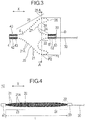
Fig. 3 is a cross-sectional view illustrating the expansion portion in the natural state. -
Fig. 4 is a plan view illustrating the expansion portion in a stretched state. -
Fig. 5 is a cross-sectional view taken along line A-A inFig. 3 . -
Fig. 6 is a cross-sectional view illustrating an intravascular state,Fig. 6(A) illustrates a state when the filter device is inserted into a blood vessel,Fig. 6(B) illustrates a state where the expansion portion is expanded inside the blood vessel, andFig. 6(C) illustrates a state where the expansion portion is turned back. -
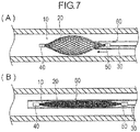
Fig. 7 is a cross-sectional view illustrating an intravascular state,Fig. 7(A) illustrates a state where a proximal portion of the expansion portion is recovered to a sheath, andFig. 7(B) illustrates a state where the whole expansion portion is recovered to the sheath. - Hereinafter, an embodiment of the present invention will be described with reference to the drawings. Dimensional proportions in the drawings are exaggerated and different from actual proportions for convenience of description, in some cases.
- A
filter device 10 according to the embodiment of the present invention is used to collect an object such as a thrombus, a plaque, and a calcified lesion inside a blood vessel. In the description herein, a side where a device is inserted into the blood vessel will be referred to as a "distal side", and an operating hand-side will be referred to as a "proximal side". A biological lumen into which thefilter device 10 is inserted is not limited to the blood vessel, and for example, may be a vessel duct, a ureter, a bile duct, an oviduct, or a hepatic duct. In addition, the object to be collected is not necessarily limited to the thrombus, the plaque or the calcified lesion, and all objects that may exist inside the biological lumen may be applicable. - As illustrated in
Figs. 1 to 3 , thefilter device 10 includes anexpansion portion 20 which is a mesh-shaped tubular body, a distalside interlock portion 40 located on a distal side of theexpansion portion 20, a proximalside interlock portion 50 located on a proximal side of theexpansion portion 20, and anelongated shaft portion 30 interlocked with the proximalside interlock portion 50. - The
shaft portion 30 is an elongated wire extending from an operator' s hand-side to the proximalside interlock portion 50. A distal side end portion of theshaft portion 30 is connected to the proximalside interlock portion 50. A material for forming theshaft portion 30 is not particularly limited. However, for example, stainless steel or a shape memory alloy can be preferably used. - The
expansion portion 20 includes a plurality of elastically deformablelinear bodies 21. Thelinear body 21 is braided in a mesh shape to form a tubular body having a small diameter in both ends. The plurality oflinear bodies 21 are braided to form agap 21A between thelinear bodies 21. Theexpansion portion 20 is interposed between the distalside interlock portion 40 and the proximalside interlock portion 50. - As illustrated in
Fig. 3 , the distalside interlock portion 40 includes an inner tube 41 located inside thelinear body 21 and anouter tube 42 located outside thelinear body 21. A distal portion of thelinear body 21 is pinched and fixed between the inner tube 41 and theouter tube 42. An inner surface side of the inner tube 41 is a guide wire lumen 43 into which a guide wire can be inserted. - The proximal
side interlock portion 50 includes an inner tube 51 located inside thelinear body 21 and anouter tube 52 located outside the inner tube 51. A proximal portion of thelinear body 21 and a distal portion of theshaft portion 30 are pinched and fixed between the inner tube 51 and theouter tube 52. Therefore, the proximalside interlock portion 50 is movable together with theshaft portion 30. An inner surface side of the inner tube 51 is aguide wire lumen 53 into which a guide wire can be inserted. - The
expansion portion 20 is accommodated in a sheath 60 (refer toFig. 6(A) ) until theexpansion portion 20 is delivered to a desired position. In this manner, as illustrated inFig. 4 , theexpansion portion 20 elastically deforms, and is brought into a stretched state where an outer diameter thereof decreases. In the stretched state, theexpansion portion 20 is not turned back. When theexpansion portion 20 is in the stretched state, the proximalside interlock portion 50 and the distalside interlock portion 40 are separated in an axial direction X of theexpansion portion 20. Theexpansion portion 20 includes aproximal gathering portion 22 which is a proximal portion of theexpansion portion 20 in the stretched state. Theproximal gathering portion 22 is located on the distal side of the proximalside interlock portion 50, and the plurality oflinear bodies 21 are gathered therein. - As illustrated in
Figs. 1 to 3 , in a natural state where theexpansion portion 20 is released from thesheath 60 and no external force is applied thereto, theexpansion portion 20 is brought into a turned-back state where theexpansion portion 20 is turned back in the axial direction X while a diameter of theexpansion portion 20 is enlarged due to a self-elastic force (restoring force) of thelinear body 21. In the turned-back state, the direction in which both side portions interposing a turned-back portion turned back in the axial direction X extend from the turned-back portion has a component facing the same direction along the axial direction X. The turned-back portion is orthogonal to the axial direction X. When theexpansion portion 20 is in the turned-back state, the proximalside interlock portion 50 and the distalside interlock portion 40 which are located in both ends of theexpansion portion 20 in the axial direction X move close to each other. A distance is changed between the proximalside interlock portion 50 and the distalside interlock portion 40. Accordingly, an outer diameter of the braidedexpansion portion 20 can be changed. Theexpansion portion 20 is accommodated again in thesheath 60. In this manner, the turned-back state is released, and theexpansion portion 20 is brought into the stretched state again (refer toFig. 7 (B) ) . - As illustrated in
Figs. 3 and 4 , theexpansion portion 20 includes adistal portion 23 interlocked with the distalside interlock portion 40 and aproximal portion 24 interlocked with the proximalside interlock portion 50. In the turned-back state, as illustrated inFig. 3 , theproximal portion 24 enters the inside of thedistal portion 23 having a cup shape open to the proximal side. That is, theexpansion portion 20 is shaped in advance to have the cup shape. For example, theexpansion portion 20 can be shaped by being held in a predetermined shape, being accommodated inside a mold, and being heated. - As illustrated in
Figs. 3 and5 , thedistal portion 23 has amaximum expansion portion 25 having a largest diameter in a natural state. In the natural state, theexpansion portion 20 has a first turned-back portion 26 forming a shape projecting in a proximal direction, a second turned-back portion 27 forming a shape projecting in a distal direction, and acentral portion 28 located between the first turned-back portion 26 and the second turned-back portion 27. The first turned-back portion 26 is located between thedistal portion 23 and the second turned-back portion 27. The second turned-back portion 27 is located between the first turned-back portion 26 and theproximal portion 24. In a state where theexpansion portion 20 is turned back, inner peripheral surfaces of thetubular expansion portion 20 are separated from each other without being in contact with each other. In the natural state, theexpansion portion 20 has a three-layer structure by being turned back at two locations of the first turned-back portion 26 and the second turned-back portion 27. Respective layers of the three-layer structure are separated with a space therebetween. - As illustrated in
Fig. 3 , in theexpansion portion 20, in the natural state, theproximal gathering portion 22 is located in the vicinity of a turned-back cross section P1 which is a cross section in which the first turned-back portion 26 is located, and which is a cross section orthogonal to the axial direction X. In this case, a radius of curvature of the second turned-back portion 27 is large compared to a case where theproximal gathering portion 22 is located on the distal side from the vicinity of the turned-back cross section P1. In this manner, a diameter of themaximum expansion portion 25 increases, and a force received by theexpansion portion 20 from a biological lumen wall increases. Therefore, in thefilter device 10, a fixing force can be further improved inside the biological lumen. Theproximal gathering portion 22 may not be located in the vicinity of the turned-back cross section P1. In addition, in the natural state, theexpansion portion 20 has three layers in a maximum portion cross section P2 which is a cross section in which themaximum expansion portion 25 is located, and which is a cross section orthogonal to the axial direction X. Theexpansion portion 20 may not have the three layers in the maximum portion cross section P2. Theexpansion portion 20 preferably has the three layers at least in any cross section orthogonal to the axial direction X. Theexpansion portion 20 may not be turned back in the natural state. - The
linear body 21 is formed of a Ni-Ti alloy which is a superelastic alloy (shape memory alloy). Therefore, theexpansion portion 20 has a highly elastic force. Thelinear body 21 is formed by plain weaving or twill weaving, and is braided in a tubular shape. The plain weaving is a weaving method of alternately raising and lowering warp yarns and weft yarns. The twill weaving is a weaving method of repeatedly causing the warp yarn to pass below one of the weft yarns after passing above a plurality of the weft yarns. Compared to the plain weaving, the twill weaving has fewer intersections where the warp yarn and the weft yarn are vertically interchanged with each other. In a case where the number of thelinear bodies 21 is large, an intersection position of thelinear bodies 21 formed by the twill weaving is unlikely to be shifted. The reason is as follows. In a case where the number of thelinear bodies 21 is large, when the warp yarn and the weft yarn are vertically less interchanged with each other, a shape of thelinear body 21 is stabilized. In a case where the number of thelinear bodies 21 is small, an intersection position of thelinear bodies 21 formed by the plain weaving is unlikely to be shifted. The reason is as follows. In a case where the number of thelinear bodies 21 is small, when the warp yarn and the weft yarn are vertically more interchanged with each other, the shape of thelinear body 21 is stabilized. - A wire diameter d of the
linear body 21 is not particularly limited, but is preferably 0.10 to 0.25 mm, more preferably 0.12 to 0.20 mm, and much more preferably 0.14 to 0.19 mm. Since theexpansion portion 20 has the suitable wire diameter d, theexpansion portion 20 can achieve a suitable fixing force inside the biological lumen. Furthermore, since theexpansion portion 20 has the suitable wire diameter d, theexpansion portion 20 can achieve suitable flexibility for being pulled and recovered into a pipe body such as thesheath 60 in a state where theexpansion portion 20 indwells the biological lumen (refer toFigs. 7(A) and 7(B) ). When the wire diameter d of thelinear body 21 is excessively large, theexpansion portion 20 is unlikely to be turned back. Therefore, when a proximal portion of theexpansion portion 20 is pushed in the distal direction to turn back theexpansion portion 20, theexpansion portion 20 is not turned back, and is likely to slip on the biological lumen wall. When the wire diameter d of thelinear body 21 is excessively small, a contact force of theexpansion portion 20 with respect to the biological lumen wall decreases. Therefore, when the proximal portion of theexpansion portion 20 is pushed in the distal direction to turn back theexpansion portion 20, theexpansion portion 20 is likely to slip on the biological lumen wall. - It is preferable that the
linear body 21 has two or more types of wire rods having different wire diameters d. In this manner, in a non-turned-back state, the proximal portion is pushed in the distal direction. Accordingly, thelinear body 21 which is thin and likely to be bent serves as a starting point, and theexpansion portion 20 is likely to be brought into a turned-back state. Thelinear body 21 is braided around a central axis of theexpansion portion 20 to be wound in two directions (forward direction and reverse direction). Therefore, theexpansion portion 20 has a plurality oflinear bodies 21 wound in the forward direction and a plurality oflinear bodies 21 wound in the reverse direction. Then, it is preferable that the plurality oflinear bodies 21 wound in the forward direction have two or more types of wire rods having different wire diameters. Furthermore, it is preferable that the plurality oflinear bodies 21 wound in the reverse direction have two or more types of wire rods having different wire diameters. The wire diameter of all of thelinear bodies 21 wound in the forward direction may be constant. In addition, the wire diameter of all of thelinear bodies 21 wound in the reverse direction may be constant. - The number of the
linear bodies 21 is not particularly limited, but is preferably 16 to 48, more preferably 24 to 40, and much more preferably 30 to 36. When the number of thelinear bodies 21 is large, thegap 21A formed in theexpansion portion 20 decreases, and is likely to be clogged. When the number of thelinear bodies 21 is small, a size of thegap 21A formed in theexpansion portion 20 is likely to be uneven when theexpansion portion 20 is turned back. - An outer diameter D of the
maximum expansion portion 25 is not particularly limited, but is preferably 30 to 35 mm, and is more preferably 32 to 34 mm. In this manner, theexpansion portion 20 can achieve both flexibility enabling easy turning back and an expansion force enabling fixing to biological lumens having different thicknesses. Therefore, a range is widened in selecting diameters of the biological lumens to which thefilter device 10 can be applied. - A length L of the
expansion portion 20 in the axial direction X is preferably 80 to 110 mm, and is more preferably 90 to 100 mm in a stretched state where theexpansion portion 20 is most stretched to separate both ends in the axial direction X. In this manner, a length of theexpansion portion 20 in contact with the biological lumen wall can be suitably determined. Therefore, a fixing force of theexpansion portion 20 to the biological lumen can be improved, and it is possible to suppress a possibility that theexpansion portion 20 may be tilted or moved inside the biological lumen. When theexpansion portion 20 is excessively short, the fixing force to the biological lumen is reduced, and theexpansion portion 20 is likely to be tilted inside a thick biological lumen such as an inferior vena cava. When theexpansion portion 20 is excessively long, theexpansion portion 20 is likely to be moved by receiving the influence of body movements or the like. - A wire diameter of the
linear body 21 is defined as d, and a sum of d3 of all of thelinear bodies 21 forming theexpansion portion 20 is defined as S1. In this case, S1 is preferably 0.08 to 0.25 mm3, and is more preferably 0.13 to 0.17 mm3. In this manner, a force received from the biological lumen wall by theexpansion portion 20 indwelling the biological lumen increases. For example, when the number of thelinear bodies 21 having a wire diameter d1 is n1 and the number of thelinear bodies 21 having a wire diameter d2 is n2, S = n1 (d1)3 + n2 (d2)3 is satisfied. A section modulus of a wire rod having a circular cross section is Πd3/32, and is proportional to d3. Accordingly, the sum of d3 of all of thelinear bodies 21 in the cross section can be an index indicating rigidity of theexpansion portion 20. - Three times S1 is defined as S2. The
expansion portion 20 has the three-layer structure. Accordingly, S2 which is three times S1 can be an index indicating the rigidity of theexpansion portion 20 of the three-layer structure. For example, when the number of thelinear bodies 21 having the wire diameter d1 is n1 and the number of thelinear bodies 21 having the wire diameter d2 is n2, S2 = 3S1 = 3 {n1 (d1)3 + n2 (d2)3} is satisfied. An area of a circumscribed circle C of themaximum expansion portion 25 in a maximum portion cross section P2 is defined as S3. A maximum outer diameter D of thelinear body 21 in a natural state is a diameter of the circumscribed circle C. S3 is ΠD2/4. When the area S3 of the circumscribed circle C is large, a cross-sectional area of thelinear body 21 occupying S3 decreases, and the rigidity of theexpansion portion 20 is likely to be weakened. S2/S3 is preferably 4 × 10⁻⁴ to 10 × 10-4 mm, and is more preferably 4 × 10⁻⁴ to 7 × 10⁻⁴ mm. In this manner, theexpansion portion 20 fixed to the biological lumen wall can obtain suitable flexibility. Accordingly, a turned-back state where theexpansion portion 20 is fixed to the biological lumen wall can be released when theshaft portion 30 is pulled. That is, theshaft portion 30 is pulled in the turned-back state of theexpansion portion 20 indwelling the biological lumen. In this manner, while theexpansion portion 20 is in a state of being suitably held on the biological lumen wall, theproximal portion 24 can be pulled out from the inside ofdistal portion 23 in the proximal direction. Therefore, it is easy to recover (retract) theexpansion portion 20 indwelling the biological lumen. - Next, a using method and an operation of the
filter device 10 will be described. - First, a
guide wire 90 is inserted into the blood vessel. Next, a proximal side end portion of theguide wire 90 located outside the body is inserted into the guide wire lumens 43 and 53 (refer toFig. 3 ) of thefilter device 10. Subsequently, as illustrated inFig. 6(A) , thefilter device 10 is caused to reach a target position along theguide wire 90. - Next, the
sheath 60 is moved to the proximal side while the movement of theshaft portion 30 of thefilter device 10 is restrained by hand. In this manner, theexpansion portion 20 is released from thesheath 60 as illustrated inFig. 6(B) . A pushing member (not illustrated) inserted into thesheath 60 may be used to push theexpansion portion 20 from thesheath 60. - When the
expansion portion 20 is released from thesheath 60, the proximalside interlock portion 50 and the distalside interlock portion 40 move closer to each other. Then, theexpansion portion 20 expands due to a self-restoring force, and comes into contact with a vascular inner wall surface. At this time, theexpansion portion 20 is in a stretched state where theexpansion portion 20 is not turned back. Theexpansion portion 20 may be brought into a turned-back state by being released from thesheath 60. - Next, the
shaft portion 30 is moved to the distal side, and the proximalside interlock portion 50 is pushed into the distal side. In this manner, as illustrated inFig. 6(C) , theexpansion portion 20 is brought into a turned-back state of being turned back in the first turned-back portion 26. Thesheath 60 may be moved in the distal direction instead of theshaft portion 30. In this manner, thesheath 60 may push the proximal portion of theexpansion portion 20 to turn back theexpansion portion 20. Theexpansion portion 20 is formed in a mesh shape. Accordingly, theexpansion portion 20 bites into the vascular inner wall surface, and is firmly fixed thereto. A maximum diameter of theexpansion portion 20 in a natural state is larger than the diameter of the blood vessel to which theexpansion portion 20 is inserted. Therefore, theexpansion portion 20 is brought into a state where theexpansion portion 20 is not completely expanded inside the blood vessel, and an expansion force is generated so that theexpansion portion 20 is effectively fixed to a vascular wall. Theproximal gathering portion 22 of theexpansion portion 20 is located in the vicinity of the turned-back cross section P1 where the first turned-back portion 26 is located. Thereafter, theguide wire 90 is removed. Theguide wire 90 may not be removed. - Next, for example, on an upstream side of the
expansion portion 20, an object such as a plaque or a calcified lesion attached to the blood vessel of the inferior vena cava or the like is broken. Abroken object 100 reaches theexpansion portion 20, located on a downstream side. Blood can pass through theexpansion portion 20 through thegap 21A. Then, theobject 100 reaching theexpansion portion 20 together with the blood is collected in theexpansion portion 20. Theexpansion portion 20 has a recessed shape in which the proximal side which is the upstream side of a blood flow is open. Accordingly, theobject 100 can be effectively collected. - As illustrated in
Figs. 3 ,5, and 6(C) , in a turned-back state, theexpansion portion 20 is a state where the inner surfaces are separated from each other without being in contact with each other. Therefore, a space is formed between respective layers of the three-layer structure. Therefore, thegap 21A functioning as a filter of theexpansion portion 20 can be satisfactorily maintained. Therefore, the blood flowing through thegap 21A of theexpansion portion 20 can be suitably maintained, and burden on a living body can be reduced. In addition, the inner surfaces of theexpansion portion 20 do not come into contact with each other. Accordingly, a range functioning as the filter of theexpansion portion 20 can be widely secured. - Next, the
object 100 collected in theexpansion portion 20 is removed. For example, theobject 100 collected in theexpansion portion 20 is aspirated and removed by thesheath 60 provided with an aspiration force from the proximal side. A method of removing theobject 100 collected in theexpansion portion 20 is not limited. - After a
thrombus 100 is completely aspirated by thesheath 60, as illustrated inFig. 7 (A) , thesheath 60 is pushed in the distal direction while the movement of theshaft portion 30 is restrained by hand. At this time, theshaft portion 30 may be pulled to the proximal side. In this manner, while the proximalside interlock portion 50 enters the inside of thesheath 60, the proximalside interlock portion 50 is separated from the distalside interlock portion 40. Then, theexpansion portion 20 is brought into a stretched state from a turned-back state, and is accommodated inside thesheath 60 from the proximal side. - As illustrated in
Fig. 7 (B) , after theexpansion portion 20 is accommodated inside thesheath 60, thefilter device 10 is removed from the blood vessel together with thesheath 60, thereby completing the procedure. - As described above, in the
filter device 10 according to the present embodiment, thefilter device 10 inserted into the biological lumen to collect the object includes theelongated shaft portion 30, and the elastically deformabletubular expansion portion 20 interlocked with theshaft portion 30, and braided with the plurality oflinear bodies 21 formed of a Ni-Ti alloy to include thegap 21A. In a case where the wire diameter of thelinear body 21 is defined as d and the sum of d3 of all of thelinear bodies 21 is defined as S1, S1 is 0.08 to 0.25 mm3. - In the
filter device 10 configured as described above, a force received from the biological lumen wall by theexpansion portion 20 indwelling the biological lumen increases. Therefore, thefilter device 10 can improve the fixing force inside the biological lumen. In a natural state, theexpansion portion 20 may be turned back or may not be turned back in the axial direction. For example, in theexpansion portion 20, in a cross section which is parallel to an axis and where the axis is located, a distal portion of theexpansion portion 20 which forms a shape projecting outward in a radial direction and a proximal portion of theexpansion portion 20 which forms a shape projecting inward in the radial direction may be interlocked with each other at a tangent line perpendicular to the axis. A portion from the first turned-back portion 26 to the second turned-back portion 27 may be located outside thedistal portion 23. - The
expansion portion 20 has thedistal portion 23, theproximal portion 24, the first turned-back portion 26 turned back in the axial direction X between thedistal portion 23 and theproximal portion 24 and forming a shape projecting in the proximal direction, and the second turned-back portion 27 turned back in the axial direction X between the first turned-back portion 26 and theproximal portion 24 and forming a shape projecting in the distal direction. In this manner, the expansion force of theexpansion portion 20 is increased by being turned back, and the force received from the biological lumen wall by theexpansion portion 20 increases. Therefore, thefilter device 10 can improve the fixing force inside the biological lumen. - The
expansion portion 20 has theproximal gathering portion 22 in which the plurality oflinear bodies 21 gather in the proximal portion, and theproximal gathering portion 22 is located in the vicinity of the maximum portion cross section P2 orthogonal to the axial direction X in which the first turned-back portion 26 is located. In this manner, the expansion force of theexpansion portion 20 increases, and the force received from the biological lumen wall by theexpansion portion 20 increases. Therefore, thefilter device 10 can improve the fixing force inside the biological lumen. - The
expansion portion 20 has three layers in the maximum portion cross section P2 orthogonal to the axial direction X in which themaximum expansion portion 25 having the largest diameter is located. In this manner, theexpansion portion 20 has the three layers at a position of themaximum expansion portion 25 which is likely to come into contact with the biological lumen wall. Accordingly, the expansion force increases, and the force received from the biological lumen wall by theexpansion portion 20 increases. Therefore, thefilter device 10 can improve the fixing force inside the biological lumen. - When 3 times S1 is defined as S2 and the area of the circumscribed circle C of the
maximum expansion portion 25 in a cross section orthogonal to the axial direction X in which themaximum expansion portion 25 is located is defined as S3, it is preferable that S2/S3 is 4 × 10⁻⁴ to 10 × 10-4 mm. In this manner, theexpansion portion 20 fixed to the biological lumen wall obtains suitable flexibility. Accordingly, when theshaft portion 30 is pulled, a turned-back state of theexpansion portion 20 which is fixed to the biological lumen wall can be satisfactorily released. That is, theshaft portion 30 is pulled in the turned-back state of theexpansion portion 20 indwelling the biological lumen. In this manner, while theexpansion portion 20 is in a state of being suitably held in the biological lumen wall, and theproximal portion 24 can be pulled out from the inside of thedistal portion 23 in the proximal direction. Therefore, it is easy to recover theexpansion portion 20 indwelling the biological lumen. - It is preferable that the
expansion portion 20 is formed by plain weaving or twill weaving. In this manner, theexpansion portion 20 can maintain a suitable shape since an intersection position of the intersectinglinear bodies 21 is unlikely to be shifted. When the number of thelinear bodies 21 is large, the intersection position of thelinear bodies 21 formed by the twill weaving is unlikely to be shifted. When the number of thelinear bodies 21 is small, the intersection position of thelinear bodies 21 formed by the plain weaving is unlikely to be shifted. Theexpansion portion 20 can maintain a suitable fixing force since the intersection position is unlikely to be shifted. - The outer diameter of the
maximum expansion portion 25 having the largest diameter of theexpansion portion 20 is preferably 30 to 35 mm. In this manner, theexpansion portion 20 can achieve both flexibility enabling easy turning back and the expansion force enabling fixing to the biological lumens having different diameters. Therefore, a range is widened in selecting the diameters of the biological lumens to which thefilter device 10 can be applied. - The wire diameter d of the
linear body 21 is preferably 0.10 to 0.25 mm. In this manner, since theexpansion portion 20 has the suitable wire diameter d, theexpansion portion 20 achieves a suitable fixing force inside the biological lumen. Furthermore, since theexpansion portion 20 has the suitable wire diameter d, theexpansion portion 20 can achieve suitable flexibility for being pulled into a pipe body such as thesheath 60 and recovered in a state where the expansion portion indwells the biological lumen. The outer diameter of the pipe body such as thesheath 60 which recovers thelinear body 21 is 7 Fr to 9 Fr, and preferably 8 Fr. 1 Fr is approximately 0.33 mm. - It is preferable that the
linear body 21 has two or more types of wire rods having different wire diameters d. In this manner, the proximal portion is pushed in the distal direction inside the biological lumen. Accordingly, thelinear body 21 which is thin and likely to be bent serves as a starting point, and theexpansion portion 20 is likely to be brought into a turned-back state. - The number of the
linear bodies 21 is preferably 16 to 48. When the number of thelinear bodies 21 is large, thegap 21A formed in theexpansion portion 20 is likely to be clogged. When the number of thelinear bodies 21 is small, a size of thegap 21A formed in theexpansion portion 20 is likely to be uneven when theexpansion portion 20 is turned back. - The length of the
expansion portion 20 in the axial direction X is preferably 80 to 110 mm in a stretched state where theexpansion portion 20 is most stretched to separate both ends in the axial direction X. In this manner, the length of theexpansion portion 20 in contact with the biological lumen wall can be suitably determined. Therefore, the fixing force of theexpansion portion 20 to the biological lumen can be improved, and it is possible to suppress a possibility that theexpansion portion 20 may be tilted or moved inside the biological lumen. When theexpansion portion 20 is excessively short, the fixing force to the biological lumen is reduced, and theexpansion portion 20 is likely to be tilted inside the biological lumen. When theexpansion portion 20 is excessively long, theexpansion portion 20 is likely to be moved by receiving the influence of body movements or the like. - The present invention is not limited to the above-described embodiment, and various modifications can be made by those skilled in the art within the technical idea of the present invention. For example, the
shaft portion 30 may be interlocked with the distalside interlock portion 40 instead of the proximalside interlock portion 50. Theshaft portion 30 may be interlocked with the proximalside interlock portion 50 or the distalside interlock portion 40 to be relatively rotatable or movable. In addition, theguide wire lumens 53 and 43 may not be formed in the proximalside interlock portion 50 and the distalside interlock portion 40. - Hereinafter, examples and comparative examples of the present invention will be described. The present invention is not limited to the examples.
- Filter devices of Example 1 to 4 and Comparative Examples 1 to 3 below were prepared to perform a test for evaluating an effect of S1 (sum of d3 of all of the linear bodies) on fixing ability of the expansion portion to the blood vessel, and an effect of S1 on recovering ability of the sheath.
- 16 linear bodies having a wire diameter d = 0.12 mm and 16 linear bodies having a wire diameter d = 0.15 mm were prepared. Next, the linear bodies were braided by the plain weaving to form the expansion portion, and the filter device of Example 1 was prepared. A material for the linear body was a Ni-Ti alloy (manufactured by Daido Steel Co., Ltd.). During the braiding, the linear bodies having different wire diameters were alternately disposed in each of a group of the linear bodies aligned in the forward direction and a group of the linear bodies aligned in the reverse direction. In a natural state, the extension portion was shaped so that the expansion portion is brought into a turned-back state. The length L of the prepared expansion portion in the axial direction was 95 mm in a state where the expansion portion was most stretched in the axial direction (state where the distal side interlock portion and the proximal side interlock portion were most separated from each other) . S1 (sum of d3 of all of the linear bodies) to be calculated was 0.08 mm3.
- 16 linear bodies having a wire diameter d = 0.14 mm and 16 linear bodies having a wire diameter d = 0.18 mm were prepared. An expansion portion whose other conditions are similar to those of Example 1 was formed, and the filter device of Example 2 was prepared. S1 to be calculated was 0.14 mm3.
- 24 linear bodies having a wire diameter d = 0.12 mm and 24 linear bodies having a wire diameter d = 0.20 mm were prepared. An expansion portion whose other conditions are similar to those of Example 1 was formed, and the filter device of Example 3 was prepared. S1 to be calculated was 0.23 mm3.
- 24 linear bodies having a wire diameter d = 0.13 mm and 24 linear bodies having a wire diameter d = 0.20 mm were prepared. An expansion portion whose other conditions are similar to those of Example 1 was formed, and the filter device of Example 4 was prepared. S1 to be calculated was 0.25 mm3.
- 72 linear bodies having a wire diameter d = 0.10 mm were prepared. Next, the linear bodies were braided by the plain weaving to form the expansion portion, and the filter device of Comparative Example 1 was prepared. The material for the linear body was the Ni-Ti alloy (manufactured by Daido Steel Co., Ltd.). In a natural state, the extension portion was shaped so that the expansion portion is brought into a turned-back state. The length L of the prepared expansion portion in the axial direction was 95 mm in a state where the expansion portion was most stretched in the axial direction (state where the distal side interlock portion and the proximal side interlock portion were most separated from each other). S1 to be calculated was 0.07 mm3.
- 32 linear bodies having a wire diameter d = 0.20 mm were prepared. An expansion portion whose other conditions are similar to those of Comparative Example 1 was formed, and the filter device of Comparative Example 2 was prepared. S1 to be calculated was 0.26 mm3.
- 72 linear bodies having a wire diameter d = 0.16 mm were prepared. An expansion portion whose other conditions are similar to those of Comparative Example 1 was formed, and the filter device of Comparative Example 3 was prepared. S1 to be calculated was 0.29 mm3.
- The expansion portions of the filter devices of Examples 1 to 4 and Comparative Examples 1 to 3 were accommodated in the sheath, and were expanded after being released from the sheath inside a simulated blood vessel (excised porcine blood vessel, inner diameter: approximately 26 mm). Each expansion portion came into contact with a vascular inner wall without being turned back. Thereafter, the shaft portion was pushed in the distal direction, and the fixing ability of the expansion portion to a vascular inner wall surface was evaluated based on whether or not the expansion portion was turned back. Specifically, when the expansion portion is in a turned-back state, the fixing ability was determined to be suitable, and when the expansion portion is not in the turned-back state, the fixing ability was determined to be unsuitable.
- Furthermore, after the expansion portion indwells the simulated blood vessel, the sheath and the shaft portion were operated to attempt to recover the expansion portion into the sheath while the expansion portion is contracted. In a case where a maximum load was lower than 500 gf when the expansion portion was recovered into the sheath at a speed of 1 mm/s, it was determined that recovery resistance was small and recovering ability was suitable. In a case where the maximum load was 500 gf or higher, it was determined that the recovery resistance was great and the recovering ability was unsuitable . The load was measured by using a digital force gauge. Results are illustrated in Table 1.
[Table 1] Wire Diameter d Number of Linear Bodies Length L S1 Fixing Ability Recovering ability Comparative Example 1 0.10 mm 72 95 mm 0.07 mm3 × ○ Example 1 0.12 mm 16 95 mm 0.08 mm3 ○ ○ 0.15 mm 16 Example 2 0.14 mm 16 95 mm 0.14 mm3 ○ ○ 0.18 mm 16 Example 3 0.12 mm 24 95 mm 0.23 mm3 ○ ○ 0.20 mm 24 Example 4 0.13 mm 24 95 mm 0.25 mm3 ○ ○ 0.20 mm 24 Comparative Example 2 0.20 mm 32 95 mm 0.26 mm3 ○ × Comparative Example 3 0.16 mm 72 95 mm 0.29 mm3 ○ × - In Comparative Example 1, the expansion portion slipped on the inner wall surface of the simulated blood vessel due to an insufficient fixing force to the simulated blood vessel, and was not turned back. Therefore, the fixing ability of Comparative Example 1 was unsuitable. In contrast, in Examples 1 to 4 and Comparative Examples 2 and 3, the expansion portion had a strong fixing force to the simulated blood vessel, and was turned back without slipping on the inner wall surface of the simulated blood vessel. Therefore, the fixing ability of Examples 1 to 4 and Comparative Examples 2 and 3 was suitable.
- In Comparative Examples 2 and 3, the recovery resistance for recovering the expansion portion to the sheath was 500 kgf or higher. Therefore, the recovering ability of Comparative Examples 2 and 3 was unsuitable. In contrast, in Examples 1 to 4 and Comparative Example 1, the recovery resistance of the expansion portion was lower than 500 kgf. Therefore, the recovering ability of Examples 1 to 4 and Comparative Example 1 was suitable.
- Filter devices of Examples 5 to 8 and Comparative Examples 4 and 5 below were prepared to perform a test for evaluating an effect of S2/S3 on the fixing ability of the expansion portion to the blood vessel, and an effect of S2/S3 on the recovering ability of the sheath.
- 16 linear bodies having the wire diameter d = 0.14 mm and 16 linear bodies having the wire diameter d = 0.18 mm were prepared. The maximum outer diameter D of the expansion portion was set to 35 mm. The other conditions were the same as those in Example 1, and the filter device of Example 5 was prepared. S2/S3 to be calculated was 4 × 10⁻⁴ mm.
- The linear body the same as that in Example 5 was used. The maximum outer diameter D of the expansion portion was set to 32 mm, and the other conditions were the same as those in Example 5. The filter device of Example 6 was prepared. S2/S3 to be calculated was 5 × 10⁻⁴ mm.
- 16 linear bodies having the wire diameter d = 0.16 mm and 16 linear bodies having the wire diameter d = 0.20 mm were prepared. The maximum outer diameter D of the expansion portion was set to 35 mm. The other conditions were the same as those in Example 5, and the filter device of Example 7 was prepared. S2/S3 to be calculated was 6 × 10⁻⁴ mm.
- 24 linear bodies having the wire diameter d = 0.12 mm and 24 linear bodies having the wire diameter d = 0.20 mm were prepared. The maximum outer diameter D of the expansion portion was set to 30 mm. The other conditions were the same as those in Example 5, and the filter device of Example 8 was prepared. S2/S3 to be calculated was 10 × 10-4 mm.
- 72 linear bodies having the wire diameter d = 0.10 mm were prepared. The maximum outer diameter D of the expansion portion was set to 30 mm. The other conditions were the same as those in Example 5, and the filter device of Comparative Example 4 was prepared. S2/S3 to be calculated was 3 × 10⁻⁴ mm.
- 24 linear bodies having the wire diameter d = 0.14 mm and 24 linear bodies having the wire diameter d = 0.20 mm were prepared. The maximum outer diameter D of the expansion portion was set to 30 mm. The other conditions were the same as those in Example 5, and the filter device of Comparative Example 5 was prepared. S2/S3 to be calculated was 11 × 10-4 mm.
- The filter devices of Examples 5 to 8 and Comparative Examples 4 and 5 were used to perform an effect evaluation test on the fixing ability and the recovering ability of the expansion portion by using a method the same as that of [the effect evaluation test of S1 on the fixing ability and the recovering ability] described above. Results are illustrated in Table 2.
[Table 2] Wire Diameter d Number of Linear Bodies Maximum Outer Diameter D S1 S2/S3 Fixing Ability Recovering ability Comparative Example 4 0.10 mm 72 30 mm 0.07 mm3 3.10-4 mm × ○ Example 5 0.14 mm 16 35 mm 0.14 mm3 4 ·10-4 mm ○ ○ 0.18 mm 16 Example 6 0.14 mm 16 32 mm 0.14 mm3 5 ·10-4 mm ○ ○ 0.18 mm 16 Example 7 0.16 mm 16 35 mm 0.19 mm3 6 ·10-4 mm ○ ○ 0.20 mm 16 Example 8 0.12 mm 24 30 mm 0.23 mm 310 ·10-4 mm ○ ○ 0.20 mm 24 Comparative Example 5 0.14 mm 24 30 mm 0.26 mm3 11 ·10-4 mm ○ × 0.20 mm 24 - In Comparative Example 4, the expansion portion slipped on the inner wall surface of the simulated blood vessel due to the insufficient fixing force to the simulated blood vessel, and was not turned back. Therefore, the fixing ability of Comparative Example 4 was unsuitable. In contrast, in Examples 5 to 8 and Comparative Example 5, the expansion portion had the strong fixing force to the simulated blood vessel, and was turned back without slipping on the inner wall surface of the simulated blood vessel. Therefore, the fixing ability of Examples 5 to 8 and Comparative Example 5 was suitable.
- In Comparative Example 5, the recovery resistance for recovering the expansion portion to the sheath was 500 kgf or higher. Therefore, the recovering ability of Comparative Example 5 was unsuitable. In contrast, in Examples 5 to 8 and Comparative Example 4, the recovery resistance of the expansion portion was lower than 500 kgf. Therefore, the recovering ability of Examples 5 to 8 and Comparative Example 4 was suitable.
- Filter devices of Examples 9 to 13 below were prepared to perform a test for evaluating an effect of the maximum outer diameter D of the expansion portion in a natural state on the fixing ability of the expansion portion to the blood vessel, and an effect of the maximum outer diameter D on the recovering ability of the sheath.
- 16 linear bodies having the wire diameter d = 0.14 mm and 16 linear bodies having the wire diameter d = 0.18 mm were prepared. The maximum outer diameter of the expansion portion was set to 29 mm. The other conditions were the same as those in Example 1, and the filter device of Example 9 was prepared.
- The maximum outer diameter of the expansion portion was set to 30 mm. The other conditions were the same as those in Example 9, and the filter device of Example 10 was prepared.
- The maximum outer diameter of the expansion portion was set to 33 mm. The other conditions were the same as those in Example 9, and the filter device of Example 11 was prepared.
- The maximum outer diameter of the expansion portion was set to 35 mm. The other conditions were the same as those in Example 9, and the filter device of Example 12 was prepared.
- The maximum outer diameter of the expansion portion was set to 36 mm. The other conditions were the same as those in Example 9, and the filter device of Example 13 was prepared.
- The filter devices of Examples 9 to 13 were used to perform an effect evaluation test on the fixing ability and the recovering ability of the expansion portion by using a method the same as that of [the effect evaluation test of S1 on the fixing ability and the recovering ability] described above. Results are illustrated in Table 3.
[Table 3] Wire Diameter d Number of Linear Bodies Length L Maximum Outer Diameter D S1 Fixing Ability Recovering ability Example 9 0.14 mm 16 95 mm 29 mm 0.14 mm3 Δ ○ 0.18 mm 16 Example 10 0.14 mm 16 95 mm 30 mm 0.14 mm3 ○ ○ 0.18 mm 16 Example 11 0.14 mm 16 95 mm 33 mm 0.14 mm3 ○ ○ 0.18 mm 16 Example 12 0.14 mm 16 95 mm 35 mm 0.14 mm3 ○ ○ 0.18 mm 16 Example 13 0.14 mm 16 95 mm 36 mm 0.14 mm3 ○ Δ 0.18 mm 16 - In Example 9, the expansion portion slipped on the inner wall surface of the simulated blood vessel due to the insufficient fixing force to the simulated blood vessel, and was not turned back. Therefore, the fixing ability of Example 9 was unsuitable. In contrast, in Examples 10 to 13, the expansion portion had the strong fixing force to the simulated blood vessel, and was turned back without slipping on the inner wall surface of the simulated blood vessel. Therefore, the fixing ability of Examples 10 to 13 was suitable.
- In Example 13, the recovery resistance for recovering the expansion portion to the sheath was 500 kgf or higher. Therefore, the recovering ability of Example 13 was unsuitable. In contrast, in Examples 9 to 12, the recovery resistance of the expansion portion was lower than 500 kgf. Therefore, the recovering ability of Examples 9 to 12 was suitable.
- Filter devices of Examples 14 to 19 below were prepared to perform a test for evaluating an effect of the length L in the axial direction of the expansion portion most stretched in the axial direction on tilting stability of the expansion portion to the blood vessel, and an effect of the length L on operability.
- 16 linear bodies having the wire diameter d = 0.14 mm and 16 linear bodies having the wire diameter d = 0.18 mm were prepared. The maximum outer diameter of the expansion portion was set to 34 mm, and the length L of the expansion portion was set to 75 mm. The other conditions were the same as those in Example 1, and the filter device of Example 14 was prepared.
- The length L of the expansion portion was set to 80 mm. The other conditions were the same as those in Example 14, and the filter device of Example 15 was prepared.
- The length L of the expansion portion was set to 90 mm. The other conditions were the same as those in Example 14, and the filter device of Example 16 was prepared.
- The length L of the expansion portion was set to 100 mm. The other conditions were the same as those in Example 14, and the filter device of Example 17 was prepared.
- The length L of the expansion portion was set to 110 mm. The other conditions were the same as those in Example 14, and the filter device of Example 18 was prepared.
- The length L of the expansion portion was set to 115 mm. The other conditions were the same as those in Example 14, and the filter device of Example 19 was prepared.
- The expansion portions of the filter devices of Examples 14 to 19 were accommodated in the sheath, and were expanded after being released from the sheath inside the simulated blood vessel (excised porcine blood vessel, inner diameter: approximately 26 mm). Each expansion portion came into contact with the vascular inner wall without being turned back. Thereafter, the shaft portion was pushed in the distal direction, and the expansion portion was brought into a turned-back state. Tilting stability of the expansion portion with respect to the vascular inner wall surface was evaluated, based on whether or not the turned-back expansion portion indwelling the blood vessel was tilted with respect to the blood vessel. Specifically, when the expansion portion was tilted with respect to the vascular inner wall surface, the tilting stability was determined to be unsuitable. When not tilted, the tilting stability was determined to be suitable. In addition, a series of operability was determined until the expansion portion of the filter device was recovered to the sheath after indwelling the simulated blood vessel and being brought into a turned-back state. Results are illustrated in Table 4.
[Table 4] Wire Diameter d Number of Linear Bodies Maximum Outer Diameter D Length L S1 Tilting Stability Operability Example 14 0.14 mm 16 34 mm 75 mm 0.14 mm3 Δ ○ 0.18 mm 16 Example 15 0.14 mm 16 34 mm 80 mm 0.14 mm3 ○ ○ 0.18 mm 16 Example 16 0.14 mm 16 34 mm 90 mm 0.14 mm3 ○ ○ 0.18 mm 16 Example 17 0.14 mm 16 34 mm 100 mm 0.14 mm3 ○ ○ 0.18 mm 16 Example 18 0.14 mm 16 34 mm 110 mm 0.14 mm3 ○ ○ 0.18 mm 16 Example 19 0.14 mm 16 34 mm 115 mm 0.14 mm3 ○ Δ 0.18 mm 16 - In Example 14, the expansion portion was short in the axial direction. Accordingly, the expansion portion was tilted with respect to the simulated blood vessel. Therefore, the tilting stability of Example 14 was unsuitable. In contrast, in Examples 15 to 19, the expansion portion was long in the axial direction. Accordingly, the expansion portion was not tilted with respect to the simulated blood vessel. Therefore, the tilting stability of Examples 15 to 19 was suitable.
- In Example 19, the expansion portion was excessively long. Accordingly, the operability was unsuitable. In contrast, in Examples 14 to 18, the expansion portion was not excessively long. Accordingly, the operability was suitable.
- This application is based on
Japanese Patent Application No. 2018-183440 filed on September 28, 2018 -
- 10
- filter device
- 20
- expansion portion
- 21
- linear body
- 21A
- gap
- 22
- proximal gathering portion
- 23
- distal portion
- 24
- proximal portion
- 25
- maximum expansion portion
- 26
- first turned-back portion
- 27
- second turned-back portion
- 30
- shaft portion
- 40
- distal side interlock portion
- 50
- proximal side interlock portion
- d
- wire diameter
- D
- maximum outer diameter
- L
- length
- P1
- turned-back cross section
- P2
- maximum portion cross section
Claims (11)
- A filter device inserted into a biological lumen to collect an object, comprising:an elongated shaft portion; andan elastically deformable tubular expansion portion interlocked with the shaft portion, and braided with a plurality of linear bodies formed of a Ni-Ti alloy to include a gap,wherein in a case where a wire diameter of the linear body is defined as d and a sum of d3 of all of the linear bodies is defined as S1, S1 is 0.08 to 0.25 mm3.
- The filter device according to Claim 1,
wherein the expansion portion hasa distal portion,a proximal portion,a first turned-back portion turned back in an axial direction between the distal portion and the proximal portion to form a projecting shape in a proximal direction, anda second turned-back portion turned back in the axial direction between the first turned-back portion and the proximal portion to form a projecting shape in a distal direction. - The filter device according to Claim 2,
wherein the expansion portion has a proximal gathering portion in which the plurality of linear bodies gather in the proximal portion, and
the proximal gathering portion is located in the vicinity of a cross section orthogonal to the axial direction in which the first turned-back portion is located. - The filter device according to Claim 2 or 3,
wherein the expansion portion has three layers in a cross section orthogonal to the axial direction in which a maximum expansion portion having a largest diameter is located. - The filter device according to Claim 4,
wherein in a case where 3 times S1 is defined as S2 and an area of a circumscribed circle of the maximum expansion portion in the cross section orthogonal to the axial direction in which the maximum expansion portion is located is defined as S3, S2/S3 is 4 × 10⁻⁴ to 10 × 10-4 mm. - The filter device according to any one of Claims 1 to 5,
wherein the expansion portion is formed by plain weaving or twill weaving. - The filter device according to any one of Claims 1 to 6,
wherein an outer diameter of the maximum expansion portion having a largest diameter in the expansion portion is 30 to 35 mm. - The filter device according to any one of Claims 1 to 7,
wherein a wire diameter of the linear body is 0.10 to 0.25 mm. - The filter device according to any one of Claims 1 to 8,
wherein the linear body has two or more types of wire rods having different wire diameters. - The filter device according to any one of Claims 1 to 9,
wherein the number of the linear bodies is 16 to 48. - The filter device according to any one of Claims 1 to 10,
wherein a length of the expansion portion in the axial direction is 80 to 110 mm in a stretched state where the expansion portion is most stretched so that both ends in the axial direction are separated.
Applications Claiming Priority (2)
| Application Number | Priority Date | Filing Date | Title |
|---|---|---|---|
| JP2018183440 | 2018-09-28 | ||
| PCT/JP2019/037029 WO2020066915A1 (en) | 2018-09-28 | 2019-09-20 | Filter device |
Publications (2)
| Publication Number | Publication Date |
|---|---|
| EP3858290A1 true EP3858290A1 (en) | 2021-08-04 |
| EP3858290A4 EP3858290A4 (en) | 2021-10-20 |
Family
ID=69950102
Family Applications (1)
| Application Number | Title | Priority Date | Filing Date |
|---|---|---|---|
| EP19865963.3A Pending EP3858290A4 (en) | 2018-09-28 | 2019-09-20 | FILTRATION DEVICE |
Country Status (5)
| Country | Link |
|---|---|
| US (1) | US11672642B2 (en) |
| EP (1) | EP3858290A4 (en) |
| JP (1) | JP7437312B2 (en) |
| CN (1) | CN112638318B (en) |
| WO (1) | WO2020066915A1 (en) |
Family Cites Families (21)
| Publication number | Priority date | Publication date | Assignee | Title |
|---|---|---|---|---|
| EP0934092A4 (en) * | 1997-03-06 | 2008-03-26 | Boston Scient Scimed Inc | DEVICE AND METHOD FOR DISTAL PROTECTION |
| US7229463B2 (en) * | 1999-07-30 | 2007-06-12 | Angioguard, Inc. | Vascular filter system for cardiopulmonary bypass |
| US20030176884A1 (en) * | 2002-03-12 | 2003-09-18 | Marwane Berrada | Everted filter device |
| US7544202B2 (en) * | 2004-06-25 | 2009-06-09 | Angiodynamics, Inc. | Retrievable blood clot filter |
| US20060041271A1 (en) * | 2004-08-20 | 2006-02-23 | Gjalt Bosma | Vascular filter with sleeve |
| US20080147111A1 (en) * | 2005-01-03 | 2008-06-19 | Eric Johnson | Endoluminal Filter With Fixation |
| US8152833B2 (en) * | 2006-02-22 | 2012-04-10 | Tyco Healthcare Group Lp | Embolic protection systems having radiopaque filter mesh |
| US8177834B2 (en) * | 2007-03-12 | 2012-05-15 | Cook Medical Technologies Llc | Woven fabric with shape memory element strands |
| US9414842B2 (en) * | 2007-10-12 | 2016-08-16 | St. Jude Medical, Cardiology Division, Inc. | Multi-component vascular device |
| EP2329794B1 (en) * | 2009-12-07 | 2014-07-23 | University of Limerick | A perfusion device |
| US9770319B2 (en) * | 2010-12-01 | 2017-09-26 | Surefire Medical, Inc. | Closed tip dynamic microvalve protection device |
| JP6636908B2 (en) | 2013-03-15 | 2020-01-29 | テルモ株式会社 | Embolism prevention device |
| US9968740B2 (en) | 2014-03-25 | 2018-05-15 | Surefire Medical, Inc. | Closed tip dynamic microvalve protection device |
| EP3213699A4 (en) | 2014-10-27 | 2018-04-18 | Terumo Kabushiki Kaisha | Medical device |
| JP2018126173A (en) * | 2015-06-16 | 2018-08-16 | テルモ株式会社 | Medical device and treatment method |
| US9700332B2 (en) * | 2015-10-23 | 2017-07-11 | Inari Medical, Inc. | Intravascular treatment of vascular occlusion and associated devices, systems, and methods |
| US10456233B2 (en) * | 2015-12-22 | 2019-10-29 | Cook Medical Technologies Llc | Intravascular filter cut from sheet metal |
| JP2019187456A (en) * | 2016-08-29 | 2019-10-31 | テルモ株式会社 | Medical device and treatment method |
| EP3505091B1 (en) | 2016-08-29 | 2022-09-21 | Terumo Kabushiki Kaisha | Medical device |
| CN116421266A (en) * | 2016-10-24 | 2023-07-14 | 伊纳里医疗有限公司 | Device and method for treating vascular occlusion |
| JP6939054B2 (en) | 2017-04-26 | 2021-09-22 | 株式会社三洋物産 | Pachinko machine |
-
2019
- 2019-09-20 EP EP19865963.3A patent/EP3858290A4/en active Pending
- 2019-09-20 WO PCT/JP2019/037029 patent/WO2020066915A1/en not_active Ceased
- 2019-09-20 JP JP2020549140A patent/JP7437312B2/en active Active
- 2019-09-20 CN CN201980056869.9A patent/CN112638318B/en active Active
-
2021
- 2021-03-08 US US17/195,606 patent/US11672642B2/en active Active
Also Published As
| Publication number | Publication date |
|---|---|
| US11672642B2 (en) | 2023-06-13 |
| US20210186674A1 (en) | 2021-06-24 |
| JP7437312B2 (en) | 2024-02-22 |
| CN112638318A (en) | 2021-04-09 |
| CN112638318B (en) | 2024-01-12 |
| EP3858290A4 (en) | 2021-10-20 |
| WO2020066915A1 (en) | 2020-04-02 |
| JPWO2020066915A1 (en) | 2021-08-30 |
Similar Documents
| Publication | Publication Date | Title |
|---|---|---|
| AU2021236459B2 (en) | Clot retrieval device for ischemic stroke treatment | |
| US11559320B2 (en) | Inverting thrombectomy apparatuses and methods | |
| US10292804B2 (en) | Embolectomy devices | |
| US20130053882A1 (en) | Embolic material excision trapping device | |
| CN112888407A (en) | Medical implant delivery system | |
| US8652196B2 (en) | Stent | |
| CN115209833A (en) | Clot removal distal protection method | |
| KR20210129604A (en) | A floating clot retrieval device for removing clots from a blood vessel | |
| CN110996845A (en) | Device for removing clots | |
| US11672642B2 (en) | Filter device | |
| US12446906B2 (en) | Clot retrieval device for ischemic stroke treatment | |
| KR20220057225A (en) | Clot removal device | |
| JP6749694B2 (en) | Device for capturing embolic substances | |
| JP3815828B2 (en) | Tubular organ treatment tool | |
| JP6749695B2 (en) | Device for capturing embolic substances |
Legal Events
| Date | Code | Title | Description |
|---|---|---|---|
| STAA | Information on the status of an ep patent application or granted ep patent |
Free format text: STATUS: THE INTERNATIONAL PUBLICATION HAS BEEN MADE |
|
| PUAI | Public reference made under article 153(3) epc to a published international application that has entered the european phase |
Free format text: ORIGINAL CODE: 0009012 |
|
| STAA | Information on the status of an ep patent application or granted ep patent |
Free format text: STATUS: REQUEST FOR EXAMINATION WAS MADE |
|
| 17P | Request for examination filed |
Effective date: 20210331 |
|
| AK | Designated contracting states |
Kind code of ref document: A1 Designated state(s): AL AT BE BG CH CY CZ DE DK EE ES FI FR GB GR HR HU IE IS IT LI LT LU LV MC MK MT NL NO PL PT RO RS SE SI SK SM TR |
|
| A4 | Supplementary search report drawn up and despatched |
Effective date: 20210922 |
|
| RIC1 | Information provided on ipc code assigned before grant |
Ipc: A61F 2/01 20060101AFI20210916BHEP |
|
| DAV | Request for validation of the european patent (deleted) | ||
| DAX | Request for extension of the european patent (deleted) | ||
| STAA | Information on the status of an ep patent application or granted ep patent |
Free format text: STATUS: EXAMINATION IS IN PROGRESS |
|
| 17Q | First examination report despatched |
Effective date: 20251021 |