EP3858270A1 - Seal assemblies for surgical access assemblies - Google Patents
Seal assemblies for surgical access assemblies Download PDFInfo
- Publication number
- EP3858270A1 EP3858270A1 EP21153953.1A EP21153953A EP3858270A1 EP 3858270 A1 EP3858270 A1 EP 3858270A1 EP 21153953 A EP21153953 A EP 21153953A EP 3858270 A1 EP3858270 A1 EP 3858270A1
- Authority
- EP
- European Patent Office
- Prior art keywords
- seal
- assembly
- sections
- support member
- seal sections
- Prior art date
- Legal status (The legal status is an assumption and is not a legal conclusion. Google has not performed a legal analysis and makes no representation as to the accuracy of the status listed.)
- Granted
Links
Images




Classifications
-
- A—HUMAN NECESSITIES
- A61—MEDICAL OR VETERINARY SCIENCE; HYGIENE
- A61B—DIAGNOSIS; SURGERY; IDENTIFICATION
- A61B17/00—Surgical instruments, devices or methods
- A61B17/34—Trocars; Puncturing needles
- A61B17/3462—Trocars; Puncturing needles with means for changing the diameter or the orientation of the entrance port of the cannula, e.g. for use with different-sized instruments, reduction ports, adapter seals
-
- A—HUMAN NECESSITIES
- A61—MEDICAL OR VETERINARY SCIENCE; HYGIENE
- A61B—DIAGNOSIS; SURGERY; IDENTIFICATION
- A61B17/00—Surgical instruments, devices or methods
- A61B17/34—Trocars; Puncturing needles
-
- A—HUMAN NECESSITIES
- A61—MEDICAL OR VETERINARY SCIENCE; HYGIENE
- A61B—DIAGNOSIS; SURGERY; IDENTIFICATION
- A61B17/00—Surgical instruments, devices or methods
- A61B17/00234—Surgical instruments, devices or methods for minimally invasive surgery
-
- A—HUMAN NECESSITIES
- A61—MEDICAL OR VETERINARY SCIENCE; HYGIENE
- A61B—DIAGNOSIS; SURGERY; IDENTIFICATION
- A61B17/00—Surgical instruments, devices or methods
- A61B17/34—Trocars; Puncturing needles
- A61B17/3417—Details of tips or shafts, e.g. grooves, expandable, bendable; Multiple coaxial sliding cannulas, e.g. for dilating
-
- A—HUMAN NECESSITIES
- A61—MEDICAL OR VETERINARY SCIENCE; HYGIENE
- A61B—DIAGNOSIS; SURGERY; IDENTIFICATION
- A61B17/00—Surgical instruments, devices or methods
- A61B17/34—Trocars; Puncturing needles
- A61B17/3417—Details of tips or shafts, e.g. grooves, expandable, bendable; Multiple coaxial sliding cannulas, e.g. for dilating
- A61B17/3421—Cannulas
- A61B17/3423—Access ports, e.g. toroid shape introducers for instruments or hands
-
- A—HUMAN NECESSITIES
- A61—MEDICAL OR VETERINARY SCIENCE; HYGIENE
- A61B—DIAGNOSIS; SURGERY; IDENTIFICATION
- A61B17/00—Surgical instruments, devices or methods
- A61B17/34—Trocars; Puncturing needles
- A61B17/3474—Insufflating needles, e.g. Veress needles
-
- A—HUMAN NECESSITIES
- A61—MEDICAL OR VETERINARY SCIENCE; HYGIENE
- A61B—DIAGNOSIS; SURGERY; IDENTIFICATION
- A61B17/00—Surgical instruments, devices or methods
- A61B17/34—Trocars; Puncturing needles
- A61B17/3498—Valves therefor, e.g. flapper valves, slide valves
-
- F—MECHANICAL ENGINEERING; LIGHTING; HEATING; WEAPONS; BLASTING
- F16—ENGINEERING ELEMENTS AND UNITS; GENERAL MEASURES FOR PRODUCING AND MAINTAINING EFFECTIVE FUNCTIONING OF MACHINES OR INSTALLATIONS; THERMAL INSULATION IN GENERAL
- F16K—VALVES; TAPS; COCKS; ACTUATING-FLOATS; DEVICES FOR VENTING OR AERATING
- F16K3/00—Gate valves or sliding valves, i.e. cut-off apparatus with closing members having a sliding movement along the seat for opening and closing
- F16K3/02—Gate valves or sliding valves, i.e. cut-off apparatus with closing members having a sliding movement along the seat for opening and closing with flat sealing faces; Packings therefor
- F16K3/03—Gate valves or sliding valves, i.e. cut-off apparatus with closing members having a sliding movement along the seat for opening and closing with flat sealing faces; Packings therefor with a closure member in the form of an iris-diaphragm
-
- F—MECHANICAL ENGINEERING; LIGHTING; HEATING; WEAPONS; BLASTING
- F16—ENGINEERING ELEMENTS AND UNITS; GENERAL MEASURES FOR PRODUCING AND MAINTAINING EFFECTIVE FUNCTIONING OF MACHINES OR INSTALLATIONS; THERMAL INSULATION IN GENERAL
- F16K—VALVES; TAPS; COCKS; ACTUATING-FLOATS; DEVICES FOR VENTING OR AERATING
- F16K3/00—Gate valves or sliding valves, i.e. cut-off apparatus with closing members having a sliding movement along the seat for opening and closing
- F16K3/02—Gate valves or sliding valves, i.e. cut-off apparatus with closing members having a sliding movement along the seat for opening and closing with flat sealing faces; Packings therefor
- F16K3/04—Gate valves or sliding valves, i.e. cut-off apparatus with closing members having a sliding movement along the seat for opening and closing with flat sealing faces; Packings therefor with pivoted closure members
- F16K3/06—Gate valves or sliding valves, i.e. cut-off apparatus with closing members having a sliding movement along the seat for opening and closing with flat sealing faces; Packings therefor with pivoted closure members in the form of closure plates arranged between supply and discharge passages
-
- A—HUMAN NECESSITIES
- A61—MEDICAL OR VETERINARY SCIENCE; HYGIENE
- A61B—DIAGNOSIS; SURGERY; IDENTIFICATION
- A61B17/00—Surgical instruments, devices or methods
- A61B17/32—Surgical cutting instruments
- A61B2017/320044—Blunt dissectors
-
- A—HUMAN NECESSITIES
- A61—MEDICAL OR VETERINARY SCIENCE; HYGIENE
- A61B—DIAGNOSIS; SURGERY; IDENTIFICATION
- A61B17/00—Surgical instruments, devices or methods
- A61B17/34—Trocars; Puncturing needles
- A61B17/3417—Details of tips or shafts, e.g. grooves, expandable, bendable; Multiple coaxial sliding cannulas, e.g. for dilating
- A61B2017/3419—Sealing means between cannula and body
-
- A—HUMAN NECESSITIES
- A61—MEDICAL OR VETERINARY SCIENCE; HYGIENE
- A61B—DIAGNOSIS; SURGERY; IDENTIFICATION
- A61B17/00—Surgical instruments, devices or methods
- A61B17/34—Trocars; Puncturing needles
- A61B17/3462—Trocars; Puncturing needles with means for changing the diameter or the orientation of the entrance port of the cannula, e.g. for use with different-sized instruments, reduction ports, adapter seals
- A61B2017/3464—Trocars; Puncturing needles with means for changing the diameter or the orientation of the entrance port of the cannula, e.g. for use with different-sized instruments, reduction ports, adapter seals with means acting on inner surface of valve or seal for expanding or protecting, e.g. inner pivoting fingers
Definitions
- the present disclosure relates to surgical access assemblies for minimally invasive surgery. More particularly, the present disclosure relates to seal assemblies for surgical access assemblies.
- a working space In order to facilitate minimally invasive surgery, a working space must be created at the desired surgical site.
- An insufflation fluid typically CO 2
- CO 2 is introduced into the abdomen of the patient to create an inflated state called a pneumoperitoneum.
- Access assemblies are utilized to allow the introduction of surgical instrumentation and endoscopes (or other visualization tools). These access assemblies maintain the pressure for the pneumoperitoneum, as they have one or more seals that adapt to the surgical instrumentation.
- a "zero-seal" in the access assembly seals the access assembly in the absence of a surgical instrument in the access assembly, and an instrument seal seals around a surgical instrument that has been inserted through the access assembly.
- An access assembly includes an instrument valve housing including upper, lower, and inner housing sections and defining a cavity.
- a valve assembly is disposed within the cavity of the instrument valve housing.
- the valve assembly includes a guard assembly, and a seal assembly disposed distally of the guard assembly.
- the seal assembly includes a support member and a plurality of seal sections connected to the support member.
- the support member includes a ring portion and a seal portion disposed within the ring portion.
- the support member and the plurality of seal sections are integrally formed.
- the seal assembly includes first, second, third, fourth seal, fifth, and sixth seal sections.
- the ring portion may be hexagonal.
- Each seal section of the plurality of seal sections may include a substantially wing shape.
- An inner edge of each seal section of the plurality of seal sections may be tapered.
- each seal section of the plurality of seal sections is connected to the ring portion by a living hinge.
- Each seal section of the plurality of seal sections may overlap two adjacent seal sections of the plurality of seal sections in a clockwise direction.
- Each seal section of the plurality of seal sections may overlap two adjacent seal sections of the plurality of seal sections in a counter-clockwise direction.
- the access assembly may further include a retainer assembly including an upper retainer member, a lower retainer member, and a plurality of pins extending from one of the upper or lower retainer members. Each pin of the plurality of pins may be received through an opening in three seal sections of the plurality seal sections and through an opening in the ring portion of the support member.
- a valve assembly including a guard assembly, and a seal assembly disposed distal of the guard assembly.
- the seal assembly includes a support member and a plurality of seal sections connected to the support member.
- the support member includes a ring portion and a seal portion disposed within the ring portion.
- the support member and the plurality of seal sections are integrally formed.
- the seal assembly includes first, second, third, fourth seal, fifth, and sixth seal sections.
- the ring portion may be hexagonal.
- Each seal section of the plurality of seal sections may include a substantially wing shape.
- An inner edge of each seal section of the plurality of seal sections may be tapered.
- each seal section of the plurality of seal sections is connected to the ring portion by a living hinge.
- Each seal section of the plurality of seal sections may overlap two adjacent seal sections of the plurality of seal sections in a clockwise direction.
- Each seal section of the plurality of seal sections may overlap two adjacent seal sections of the plurality of seal sections in a counter-clockwise direction.
- the access assembly may further include a retainer assembly including an upper retainer member, a lower retainer member, and a plurality of pins extending from one of the upper or lower retainer members. Each pin of the plurality of pins may be received through an opening in three seal sections of the plurality seal sections and through an opening in the ring portion of the support member.
- a seal assembly including a support member having a ring portion and a seal portion disposed within the ring portion, and a plurality of seal sections extending from the ring portion of the support member.
- the support member and the plurality of seal sections are integrally formed.
- distal refers to that portion of the instrument, or component thereof which is farther from the user while the term “proximal” refers to that portion of the instrument or component thereof which is closer to the user.
- proximal refers to that portion of the instrument or component thereof which is closer to the user.
- about means that the numerical value is approximate and small variations would not significantly affect the practice of the disclosed embodiments. Where a numerical limitation is used, unless indicated otherwise by the context, “about” means the numerical value can vary by ⁇ 10% and remain within the scope of the disclosed embodiments.
- Surgical access assemblies with obturators are employed during minimally invasive surgery, e.g., laparoscopic surgery, and provide for the sealed access of surgical instruments into an insufflated body cavity, such as the abdominal cavity.
- the surgical access assemblies of the present disclosure include an instrument valve housing mounted on a cannula tube, and include an obturator (not shown) inserted through the valve housing and cannula.
- the obturator can have a blunt distal end, or a bladed or non-bladed penetrating distal end and can be used to incise the abdominal wall so that the surgical access assembly can be introduced into the abdomen.
- the handle of the obturator can engage or selectively lock into the instrument valve housing of the surgical access assembly.
- Surgical access assemblies are employed to tunnel through an anatomical structure, e.g., the abdominal wall, either by making a new passage through the anatomical structure or by passing through an existing opening through the anatomical structure.
- anatomical structure e.g., the abdominal wall
- the surgical access assembly with the obturator Once the surgical access assembly with the obturator has tunneled through the anatomical structure, the obturator is removed, leaving the surgical access assembly in place.
- the instrument valve housing of the surgical access assembly includes valves that prevent the escape of insufflation fluid from the body cavity, while also allowing surgical instruments to be inserted into the body cavity.
- a bladeless optical trocar obturator may be provided that permits separation of tissue planes in a surgical procedure and visualization of body tissue fibers as they are being separated, thereby permitting a controlled traversal across a body wall.
- the trocar obturator may be bladeless without being optical, e.g., without providing contemporaneous visualization thereof through the distal tip of an obturator.
- the bladeless obturator may be provided for the blunt dissection of the abdominal lining during a surgical procedure.
- trocar obturators suitable for use with the surgical access assembly of the present disclosure are known and include, for example, bladed, bladeless, blunt, optical, and non-optical.
- exemplary trocar assemblies including exemplar trocar obturators and exemplar cannulas, please refer to PCT Publication No. WO 2016/186905 ("the '905 publication”), the content of which is hereby incorporated by reference herein in its entirety.
- the surgical access assembly 100 includes a cannula 102 and an instrument valve housing 110 secured to the cannula 102.
- the surgical access assembly 100 includes a cannula 102 and an instrument valve housing 110 secured to the cannula 102.
- an exemplary surgical access assembly please refer to the '905 publication.
- the instrument valve housing 110 of the surgical access assembly 100 includes an upper housing section 112, a lower housing section 114, and an inner housing section 116.
- the upper, lower, and inner housing sections 112, 114, 116 are configured to support a valve assembly 120 on a proximal end of the cannula 102. More particularly, the inner housing section 116 is secured between the upper and lower housing sections 112, 114, and the valve assembly 120 is received between the inner and lower housing sections 116, 114.
- the upper and lower housing sections 112, 114 of the instrument valve housing 110 may be selectively attachable to, and detachable from, the inner housing section 116.
- the lower housing section 114 may be releasably or permanently attached to a cannula tube 104 ( FIG. 1 ) of the cannula 102.
- either or both of the upper and lower housing sections 112, 114 of the instrument valve housing 110 may include knurls, indentations, tabs, or be otherwise configured to facilitate engagement by a clinician.
- the surgical access assembly 100 may also include features for the stabilization of the surgical access assembly.
- the distal end of the cannula tube 104 may carry a balloon anchor or another expandable member that engages the abdomen from the interior side.
- a balloon anchor or another expandable member that engages the abdomen from the interior side.
- a feature on the opposite side of the abdominal wall may be used to further stabilize the surgical access assembly, such as adhesive tabs or adjustable foam collars.
- the upper, lower, and inner housing sections 112, 114, 116 of the instrument valve housing 110 define a longitudinal passage 111 for receipt of a surgical instrument (not shown).
- the valve assembly 120 is supported within the instrument valve housing 110 to provide sealed passage of the surgical instrument (not shown) through the surgical access assembly 100.
- the valve assembly 120 supported in the instrument valve housing 110 includes a centering mechanism 130, a guard assembly 140, a seal assembly 160, and a retainer assembly 180.
- the centering mechanism 130 of the valve assembly 120 permits radial movement of the valve assembly 120 relative to the instrument valve housing 110 when a surgical instrument is received through the valve assembly 120, and returns the valve assembly 120 to a generally centered position once the surgical instrument is withdrawn from within the instrument valve housing 110.
- the guard assembly 140 protects the seal assembly 160 during insertion and withdrawal of a surgical instrument through the seal assembly 160.
- the seal assembly 160 provides sealed passage of the surgical instrument through the instrument valve housing 110.
- the retainer assembly 180 maintains the centering mechanism 130, the guard assembly 140, and the seal assembly 160 in an aligned relationship with one another.
- the centering mechanism 130 of the valve assembly 120 is configured to maintain the valve assembly 120 centered within the instrument valve housing 110 ( FIG. 2 ) in the absence of a surgical instrument passing through the valve assembly 120.
- the centering mechanism 130 includes an outer annular ring 132, an inner annular ring 134, and a bellows 136 disposed between the outer annular ring 132 and the inner annular ring 134.
- the outer annular ring 132 is received between the inner housing section 116 and the lower housing section 114 to retain the centering mechanism 130 within the instrument valve housing 110.
- the inner annular ring 134 supports the guard assembly 140.
- the valve assembly 120 may include alternative centering mechanisms.
- the centering mechanism may include an annular base and a plurality of spokes extending from the base, as described in U.S. Pat. App. Pub. No. 2015/0025477 ("the '477 publication”), the content of which is incorporated herein by reference in its entirety. It is envisioned that the centering mechanism may include multiple sets of spokes, as disclosed in the '477 publication.
- the guard assembly 140 of the valve assembly 120 is configured to protect the seal assembly 160 as a surgical instrument (not shown) passes through the instrument valve housing 110 ( FIG. 2 ).
- the guard assembly 140 includes a ring portion 142 and first, second, third, and fourth petals 144, 146, 148, 150.
- the first, second, third, and fourth petals 144, 146, 148, 150 define an opening 141 therebetween to facilitate sealed passage of a surgical instrument (not shown) through the guard assembly 140.
- the guard assembly may include any suitable number of petals, and the petals may include flap portions of any size or configuration.
- Patent Nos. 5,895,377 and 6,569,120 (“the '377 and '120 patents") and U.S. Pat. App. Ser. Nos. 16/394,043 and 16/238,823 , the entire disclosures of which are incorporated herein by reference in their entirety.
- the seal assembly 160 of the valve assembly 120 is configured to provide a seal around an outer surface of a surgical instrument passing through the instrument valve housing 110 ( FIG. 1 ).
- the seal assembly 160 forms a flat seal body; however, it is envisioned that the aspects of the present disclosure may be modified for use with a conical seal body.
- the seal assembly 160 includes a support member 162, and first, second, third, fourth, fifth, and sixth seal sections 164, 166, 168, 170, 172, 174 secured to the support member 162 by respective connector portions 164a, 166a, 168a, 170a, 172a, 174a.
- the connector portions 164a, 166a, 168a, 170a, 172a, 174a may include one or more living hinges, as shown, or be otherwise configured to permit folding of the respective first, second, third, fourth, fifth, and sixth seal sections 164, 166, 168, 170, 172, 174 relative to the support member 162.
- the support member 162 and the first, second, third, fourth, fifth, and sixth seal sections 164, 166, 168, 170, 172, 174 of the seal assembly 160 are formed of the same material, including, for example, polyurethane, polyisoprenes, or silicone elastomers.
- the support member 162, and the first, second, third, fourth, fifth, and sixth seal sections 164, 166, 168, 170, 172, 174 may be formed of different materials.
- the support member 162 and/or the first, second, third, fourth, fifth, and sixth seal sections 164, 166, 168, 170, 172, 174 may include one or more fabric layers.
- first, second, third, fourth, fifth, and sixth seal sections 164, 166, 168, 170, 172, 174 of the seal assembly 160 define a planar configuration when the seal assembly 160 is in the folded condition ( FIG. 7 ).
- the seal assembly 160 may define a conical seal.
- the support member 162 of the seal assembly 160 includes a hexagonal body or ring portion 162a and a seal portion 162b supported within the support member 162a.
- the ring portion 162a and the seal portions 162b may be formed of the same or different materials.
- the seal portion 162b defines a central opening 161.
- the support member 162a defines a plurality of openings 163 corresponding to a plurality of pins 186 ( FIG. 3 ) extending from an upper retainer member 182 of the retainer assembly 180.
- the seal portion 162a provides additional support to the first, second, third, fourth, fifth, and sixth seal sections 164, 166, 168, 170, 172, 174 when the seal assembly 160 is in the folded configuration.
- the ring portion 162a and the seal portion 162b of the support member 162 are of unitary construction, i.e., monolithic, with the first, second, third, fourth, fifth, and sixth seal sections 164, 166, 168, 170, 172, 174.
- the ring portion 162a By incorporating the ring portion 162a with the seal portion 162b of the support member 162 of the seal assembly 160 and forming the first, second, third, fourth, fifth, and sixth seal sections 164, 166, 168, 170, 172, 174 on the ring portion 162a of the support member 162, instead of including a ring portion for the seal portion and a separate ring portion for the first, second, third, fourth, fifth, and sixth seal sections 164, 166, 168, 170, 172, 174, the number of components in the seal assembly 160, and ultimately, the valve assembly 120, is reduced.
- the incorporation of the seal portion 162b and the first, second, third, fourth, fifth, and sixth seal sections 164, 166, 168, 170, 172, 174 with the same ring portion 162 also reduces assembly time and reduces material costs.
- the first, second, third, fourth, fifth, and sixth seal sections 164, 166, 168, 170, 172, 174 of the seal assembly 160 define an opening 161a configured to receive a surgical instrument (not shown) inserted through the valve assembly 120 in a sealed manner.
- the first, second, third, fourth, fifth, and sixth seal sections 164, 166, 168, 170, 172, 174 form a non-continuous or virtual seal circumference to reduce tearing during insertion, manipulation, and/or withdrawal of a surgical instrument (not shown) through the valve assembly 120.
- Each of the first, second, third, fourth, fifth, and sixth seal sections 164, 166, 168, 170, 172, 174 of the seal assembly 160 includes a wing-shaped body.
- the first, second, third, fourth, fifth, and sixth seal sections 164, 166, 168, 170, 172, 174 are configured to partially overlap two adjacent seal sections in each of the clockwise and the counter-clockwise directions.
- the first seal section 164 is configured to partially overlap, the sixth and fifth seal sections 174, 172 in the clockwise direction and the second and third seal section 166, 168 in the counter-clockwise direction
- the second seal section 164 is configured to partially overlap the first and sixth seal sections 164, 174 in the clockwise direction and the third and fourth seal sections 164, 168 in the counter-clockwise direction
- the third seal section 166 is configured to partially overlap the second and first seal sections 166, 164 in the clockwise direction and the fourth and fifth seal section 170, 172 in the counter-clockwise direction
- the fourth seal section 170 is configured to partially overlap the third and second seal sections 168, 166 in the clockwise direction and the fifth and sixth seal sections 172, 174 in the counter-clockwise direction
- the fifth seal section 172 is configured to partially overlap the fourth and third seal sections 170, 168 in the clockwise direction and the sixth and first seal sections 174, 164 in the counter-clockwise direction
- the sixth seal section 174 is configured to partially overlap the fifth
- first, second, third, fourth, fifth, and sixth seal sections 164, 166, 168, 170, 172, 174 are folded such that the first, second, third, fourth, fifth, and sixth seal sections 164, 166, 168, 170, 172, 174 overlap in a sequential pattern in counter-clockwise direction.
- first, second, third, fourth, fifth, and sixth seal sections 164, 166, 168, 170, 172, 174 may folded to overlap in a sequential clockwise direction.
- first, second, third, fourth, fifth, and sixth seal sections 164, 166, 168, 170, 172, 174 may instead be folded in opposed pairs, i.e., first and fourth seal sections 164, 170 folded together, second and fifth seal sections, 166, 172 folded together, and third and sixth seal sections 168, 174 folded together, or in any other suitable manner.
- An inner edge 164b, 166b, 168b, 170b, 172b, 174b of the respective first, second, third, fourth, fifth, and sixth seal sections 164, 166, 168, 170, 172, 174 of the seal assembly 160 may define a V-shape, as shown, or may extend straight across.
- the V-shape defines an angle " ⁇ " from about one-hundred eighty degrees (180°) to about two-hundred seventy-five degrees (275°)( FIG. 4 ).
- the V-shape of the inner edges 164b, 166b, 168b, 170b, 172b 164b facilitates reception of a surgical instrument (not shown) through the seal assembly 160.
- Each of the first, second, third, fourth, fifth, and sixth seal sections 164, 166, 168, 170, 172, 174 defines a plurality of openings 165, 167, 169, 171, 173, 175 ( FIG. 6 ) adjacent the respective connector portions 164a, 166a, 168a, 170a, 172a, 174a of each seal section 164, 166, 168, 170, 172, 174, respectively.
- the plurality of openings 165, 167, 169, 171, 173, 175 are arranged such each opening of the plurality of openings 163 in the support member 162 is aligned with an opening of the plurality of openings 165, 167, 169, 171, 173, 175 of the respective first, second, third, fourth, fifth, and sixth seal sections 164, 166, 168, 170, 172, 174 and an opening of the plurality of openings 165, 167, 169, 171, 173, 175 of the two adjacent first, second, third, fourth, fifth, and sixth seal sections 164, 166, 168, 170, 172, 174.
- each pin of the plurality of pins 186 ( FIG.
- FIGS. 6 and 7 illustrate the method of folding the seal assembly 160.
- each of the first, second, third, fourth, fifth, and sixth seal sections 164, 166, 168, 170, 172, 174 are folded relative to the support member 162 at the respective connector portion 164a, 166a, 168a, 170a, 172a, 174a, as indicated by arrows "A", "B", “C”, “D”, “E”, and “F” respectively.
- the first, second, third, fourth, fifth, and sixth seal sections 164, 166, 168, 170, 172, 174 are folded simultaneously, with adjacent seal sections overlapping one another.
- the second seal section 166 overlaps the first seal section 164
- the third seal section 168 overlaps the second seal section 166, and so on until the first seal section 164 overlaps the sixth seal section 174.
- This overlapping or interweaving pattern increases the integrity of the seal assembly 160, i.e., reduces the likelihood of the seal assembly 160 leaking when a surgical instrument is received therethrough.
- the seal sections may be folded in any manner, including, with opposed seal sections folded together.
- FIGS. 7 and 8 illustrate the seal assembly 160 in the folded condition.
- the first, second, third, fourth, fifth, and sixth seal sections 164, 166, 168, 170, 172, 174 are disposed adjacent the seal portion 162b of the support member 162.
- FIG. 9 illustrates a bottom view of the assembled valve assembly 120.
- the seal assembly 160 is secured relative to the centering mechanism 130 and the guard assembly 140 ( FIG. 3 ) by retainer assembly 180. More particularly, the plurality of pins 186 extending from the upper retainer member 182 ( FIG. 3 ) of the retainer assembly 180 extend through the guard assembly 140, the centering mechanism 130, and the seal assembly 160, and are secured within openings 185 of the lower retainer member 184.
- the plurality of pins 186 is welded, glued, adhered, bonded or otherwise secured within the plurality of openings 185 in the lower retainer member 184 to secure the upper retainer member 182 and the lower retainer member 184 together.
- the lower retainer member 184 may instead, or additionally, include a plurality of pins (not shown) with the upper retainer member 182 defining a plurality corresponding openings (not shown). Either or both of the upper and lower retainer members 182, 184 may include locking features (not shown) for engaging the plurality of pins 186 and securing the upper retainer member 182 to the lower retainer member 184.
- seal assembly 260 a seal assembly according to another aspect of the disclosure is shown generally as seal assembly 260.
- the seal assembly 260 is substantially similar to the seal assembly 160 described hereinabove, and will only be described in detail with regards to the differences therebetween.
- the seal assembly 260 is configured to be received within the instrument valve housing 110 ( FIG. 1 ) and provide a seal around an outer surface of a surgical instrument passing through the instrument valve housing 110.
- the seal assembly 260 forms a flat seal body; however, it is envisioned that the aspects of the disclosure may be modified for use with a conical seal body.
- the seal assembly 260 includes a support member 262, and first, second, third, fourth, fifth, and sixth seal sections 264, 266, 268, 270, 272, 274 secured to the support member 262.
- the support member 262 and the first, second, third, fourth, fifth, and sixth seal sections 264, 266, 268, 270, 272, 274 of the seal assembly 260 are formed of the same material, including, for example, polyurethane, polyisoprenes, or silicone elastomers.
- the support member 262, and the first, second, third, fourth, fifth, and sixth seal sections 264, 266, 268, 270, 272, 274 are formed of different materials.
- the support member 262 and/or the first, second, third, fourth, fifth, and sixth seal sections 264, 266, 268, 270, 272, 274 may include one or more fabric layers.
- first, second, third, fourth, fifth, and sixth seal sections 264, 266, 268, 270, 272, 274 of the seal assembly 260 define a planar configuration when the seal assembly 260 is in the folded condition ( FIG. 14 ).
- the seal assembly 260 may define a conical seal when in the folded condition.
- the support member 262 of the seal assembly 260 includes a hexagonal body or ring portion 262a and a seal portion 262b supported within the support member 262a.
- the ring portion 262a and the seal portions 262b may be formed of the same or different materials.
- the seal portion 262b defines a central opening 261.
- the support member 262a defines a plurality of openings 263 ( FIG. 12 ) corresponding to the plurality of pins 186 ( FIG. 3 ) extending from the upper retainer member 182 of the retainer assembly 180.
- the seal portion 262a provides additional support to the first, second, third, fourth, fifth, and sixth seal sections 264, 266, 268, 270, 272, 274 when the seal assembly 260 is in the folded configuration ( FIG. 14 ).
- the ring portion 262a and the seal portion 262b of the support member 262 are of unitary construction, i.e., monolithic, with the first, second, third, fourth, fifth, and sixth seal sections 264, 266, 268, 270, 272, 274.
- the ring portion 262a By incorporating the ring portion 262a with the seal portion 262b of the support member 262 of the seal assembly 260 and forming the first, second, third, fourth, fifth, and sixth seal sections 264, 266, 268, 270, 272, 274 on the ring portion 262a of the support member 262, instead of including a ring portion for the seal portion and a separate ring portion for the first, second, third, fourth, fifth, and sixth seal sections 264, 266, 268, 270, 272, 274, the number of components in the seal assembly 260, and ultimately, the valve assembly 120, is reduced ( FIG. 3 ).
- the incorporation of the seal portion 262b and the first, second, third, fourth, fifth, and sixth seal sections 264, 266, 268, 270, 272, 274 with the same ring portion 262 also reduces assembly time and reduces material costs.
- the first, second, third, fourth, fifth, and sixth seal sections 264, 266, 268, 270, 272, 274 of the seal assembly 260 are identical to each other in structure and function, and will be described in detail with reference to first seal section 264 shown in FIG. 12 .
- the first seal section 264 includes a wing-shaped body secured to the support member 262 by a connector portion 264a.
- the connector portion 264a may include a single living hinge, as shown, or a plurality of living hinges ( FIG. 4 ), or may be otherwise configured to permit folding of the first seal section 264 relative to the support member 262.
- the first seal section 264 and the support member 262 may define a notch 263a on either side of the connector portion 264a to facilitate folding of the first seal section 264 relative to the support member 262.
- the notches 263a may include a triangular configuration, as shown, or may be otherwise configured to facilitate folding of the first seal section 264 relative to the support member 262.
- Inner edge 264b of the first seal section 264 of the seal assembly 260 may define a V-shape, as shown, or may extend straight across.
- the V-shape defines an angle " ⁇ " from about one-hundred eighty degrees (180°) to about two-hundred seventy-five degrees (275°).
- the V-shape of the inner edge 264b facilitates reception of a surgical instrument (not shown) through the seal assembly 260.
- Each inner edge 264b may be tapered to further facilitate reception of the surgical instrument through the seal assembly 260 in a sealed manner.
- the first seal section 264 defines a plurality of openings 265a adjacent the connector portion 264a between the first seal section 264 and the support member 262, and an opening 265b along each lateral edge 264c of the first seal section 264 adjacent the inner edge 264b of the first seal section 264.
- the lateral edges 264c of the first seal section 264 each defines a semi-circular cutout 265c between each of the openings 265b and the plurality of openings 265a.
- the cutouts 265c reduce the amount of material forming the first seal section 264.
- the cutouts 265c may allow for additional flexing of the first seal section 264.
- FIG. 13 illustrates the method of folding the seal assembly 260.
- Each of the first, second, third, fourth, fifth, and sixth seal sections 264, 266, 268, 270, 272, 274 is folded relative to the support member 262, as indicated by arrows "G", “H”, “I”, “J”, “K”, and “L” respectively.
- the first, second, third, fourth, fifth, and sixth seal sections 264, 266, 268, 270, 272, 274 are folded simultaneously, with adjacent seal sections overlapping one another. More particularly, the second seal section 266, overlaps the first seal section 264, the third seal section 268 overlaps the second seal section 266, and so on until the first seal section 264 overlaps the sixth seal section 274.
- seal sections may be folded in any manner, including, with opposed seal sections folded together.
- the plurality of openings 265a and the openings 265b of the first seal section 264 are arranged such that, when the seal assembly 260 is in the folded condition ( FIG. 14 ), each opening of the plurality of openings 263 in the support member 262 is aligned with an opening of the plurality of openings 265a of the first seal section 264, with two openings of each of the adjacent second and sixth seal sections 266 274, and with one opening of each of the third and fifth seal sections 268, 272.
- This arrangement ensures the integrity of the seal assembly 260, and more particularly, ensures the positioning of the first, second, third, fifth, and sixth seal sections 264, 266, 268, 2172, 274 relative to each other and the support member 262.
- FIG. 14 illustrates the seal assembly 260 in the folded condition.
- the first, second, third, fourth, fifth, and sixth seal sections 264, 266, 268, 270, 272, 274 of the seal assembly 260 define an opening 261a configured to receive a surgical instrument (not shown) inserted through the valve assembly 120 in a sealed manner.
- the first, second, third, fourth, fifth, and sixth seal sections 264, 266, 268, 270, 272, 274 form a non-continuous or virtual seal circumference to reduce tearing during insertion, manipulation, and/or withdrawal of a surgical instrument (not shown) through the valve assembly 120 ( FIG. 3 ).
- the first, second, third, fourth, fifth, and sixth seal sections 264, 266, 268, 270, 272, 274 are configured to partially overlap two adjacent seal sections in each of the clockwise and the counter-clockwise directions.
- first seal section 264 is configured to partially overlap, the sixth and fifth seal sections 274, 272 in the clockwise direction and the second and third seal section 266, 268 in the counter-clockwise direction
- the second seal section 264 is configured to partially overlap the first and sixth seal sections 264, 274 in the clockwise direction and the third and fourth seal sections 264, 268 in the counter-clockwise direction
- the third seal section 266 is configured to partially overlap the second and first seal sections 266, 264 in the clockwise direction and the fourth and fifth seal section 270, 272 in the counter-clockwise direction
- the fourth seal section 270 is configured to partially overlap the third and second seal sections 268, 266 in the clockwise direction and the fifth and sixth seal sections 272, 274 in the counter-clockwise direction
- the fifth seal section 272 is configured to partially overlap the fourth and third seal sections 270, 268 in the clockwise direction and the sixth and first seal sections 274, 264 in the counter-clockwise direction
- the sixth seal section 274 is configured to partially overlap the fifth and fourth seal sections 272,
- the first, second, third, fourth, fifth, and sixth seal sections 264, 266, 268, 270, 272, 274 are folded such that the first, second, third, fourth, fifth, and sixth seal sections 264, 266, 268, 270, 272, 274 overlap in a sequential pattern in counter-clockwise direction.
- the first, second, third, fourth, fifth, and sixth seal sections 264, 266, 268, 270, 272, 274 may folded to overlap in a sequential clockwise direction.
- first, second, third, fourth, fifth, and sixth seal sections 264, 266, 268, 270, 272, 274 may instead be folded in opposed pairs, i.e., first and fourth seal sections 264, 270 folded together, second and fifth seal sections, 266, 272 folded together, and third and sixth seal sections 268, 274 folded together, or in any other suitable manner.
Landscapes
- Health & Medical Sciences (AREA)
- Surgery (AREA)
- Life Sciences & Earth Sciences (AREA)
- Engineering & Computer Science (AREA)
- Animal Behavior & Ethology (AREA)
- Molecular Biology (AREA)
- Veterinary Medicine (AREA)
- Public Health (AREA)
- Biomedical Technology (AREA)
- Heart & Thoracic Surgery (AREA)
- Medical Informatics (AREA)
- Nuclear Medicine, Radiotherapy & Molecular Imaging (AREA)
- General Health & Medical Sciences (AREA)
- Pathology (AREA)
- General Engineering & Computer Science (AREA)
- Mechanical Engineering (AREA)
- Surgical Instruments (AREA)
- Prostheses (AREA)
- Gasket Seals (AREA)
Abstract
Description
- The present disclosure relates to surgical access assemblies for minimally invasive surgery. More particularly, the present disclosure relates to seal assemblies for surgical access assemblies.
- In order to facilitate minimally invasive surgery, a working space must be created at the desired surgical site. An insufflation fluid, typically CO2, is introduced into the abdomen of the patient to create an inflated state called a pneumoperitoneum. Access assemblies are utilized to allow the introduction of surgical instrumentation and endoscopes (or other visualization tools). These access assemblies maintain the pressure for the pneumoperitoneum, as they have one or more seals that adapt to the surgical instrumentation. Typically, a "zero-seal" in the access assembly seals the access assembly in the absence of a surgical instrument in the access assembly, and an instrument seal seals around a surgical instrument that has been inserted through the access assembly.
- The breadth of surgical instrumentation on the market today requires a robust seal capable of adjusting to multiple sizes and withstanding multiple insertions of surgical instrumentation. Some of the instrumentation can include sharp edges that can tear or otherwise damage seals. Therefore, it would be beneficial to have an access assembly with improved seal durability.
- An access assembly includes an instrument valve housing including upper, lower, and inner housing sections and defining a cavity. A valve assembly is disposed within the cavity of the instrument valve housing. The valve assembly includes a guard assembly, and a seal assembly disposed distally of the guard assembly. The seal assembly includes a support member and a plurality of seal sections connected to the support member. The support member includes a ring portion and a seal portion disposed within the ring portion. The support member and the plurality of seal sections are integrally formed.
- In embodiments, the seal assembly includes first, second, third, fourth seal, fifth, and sixth seal sections. The ring portion may be hexagonal. Each seal section of the plurality of seal sections may include a substantially wing shape. An inner edge of each seal section of the plurality of seal sections may be tapered.
- In some embodiments, each seal section of the plurality of seal sections is connected to the ring portion by a living hinge. Each seal section of the plurality of seal sections may overlap two adjacent seal sections of the plurality of seal sections in a clockwise direction. Each seal section of the plurality of seal sections may overlap two adjacent seal sections of the plurality of seal sections in a counter-clockwise direction.
- The access assembly may further include a retainer assembly including an upper retainer member, a lower retainer member, and a plurality of pins extending from one of the upper or lower retainer members. Each pin of the plurality of pins may be received through an opening in three seal sections of the plurality seal sections and through an opening in the ring portion of the support member.
- Also provided is a valve assembly including a guard assembly, and a seal assembly disposed distal of the guard assembly. The seal assembly includes a support member and a plurality of seal sections connected to the support member. The support member includes a ring portion and a seal portion disposed within the ring portion. The support member and the plurality of seal sections are integrally formed.
- In embodiments, the seal assembly includes first, second, third, fourth seal, fifth, and sixth seal sections. The ring portion may be hexagonal. Each seal section of the plurality of seal sections may include a substantially wing shape. An inner edge of each seal section of the plurality of seal sections may be tapered.
- In some embodiments, each seal section of the plurality of seal sections is connected to the ring portion by a living hinge. Each seal section of the plurality of seal sections may overlap two adjacent seal sections of the plurality of seal sections in a clockwise direction. Each seal section of the plurality of seal sections may overlap two adjacent seal sections of the plurality of seal sections in a counter-clockwise direction.
- The access assembly may further include a retainer assembly including an upper retainer member, a lower retainer member, and a plurality of pins extending from one of the upper or lower retainer members. Each pin of the plurality of pins may be received through an opening in three seal sections of the plurality seal sections and through an opening in the ring portion of the support member.
- In addition, provided is a seal assembly including a support member having a ring portion and a seal portion disposed within the ring portion, and a plurality of seal sections extending from the ring portion of the support member. The support member and the plurality of seal sections are integrally formed.
- The accompanying drawings, which are incorporated in and constitute a part of this specification, illustrate embodiments of the disclosure and, together with a general description of the disclosure given above, and the detailed description of the embodiments given below, serve to explain the principles of the disclosure, wherein:
-
FIG. 1 is a side perspective view of a surgical access assembly according to an embodiment of the present disclosure; -
FIG. 2 a side cross-sectional view of the surgical access assembly shown inFIG. 1 taken along section line 2-2; -
FIG. 3 is an exploded perspective view of a valve assembly, with parts separated, including a centering mechanism, a guard assembly, a seal assembly, and a retainer assembly; -
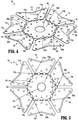
FIG. 4 is a top perspective view of the seal assembly shown inFIG. 3 , in an initial or unfolded condition; -
FIG. 5 is a top plan view of the seal assembly shown inFIG. 4 , in the initial or unfolded condition; -
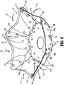
FIG. 6 is a top perspective view of the seal assembly shown inFIGS. 3 and4 , in a partially folded condition; -
FIG. 7 is a top perspective view of the seal assembly shown inFIGS. 4-6 , in a fully folded condition; -
FIG. 8 is a bottom perspective view of the seal assembly shown inFIG. 7 ; -
FIG. 9 is a bottom perspective view of the valve assembly shown inFIG. 3 , as assembled; -
FIG. 10 is a top perspective view of a seal assembly according to another aspect of the disclosure, in an initial or unfolded condition; -
FIG. 11 is a top plan view of the seal assembly shown inFIG. 10 , in the initial or unfolded condition; -
FIG. 12 is an enlarged view of the indicated area of detail shown inFIG. 11 ; -
FIG. 13 is top perspective view of the seal assembly shown inFIGS. 10 and 11 , in a partially folded condition; and -
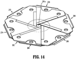
FIG. 14 is a top perspective view of the seal assembly shown inFIGS. 10-13 , in a fully folded condition. - Particular embodiments of the present disclosure are described hereinbelow with reference to the accompanying drawings; however, it is to be understood that the disclosed embodiments are merely exemplary of the disclosure and may be embodied in various forms. Well-known functions or constructions are not described in detail to avoid obscuring the present disclosure in unnecessary detail. Therefore, specific structural and functional details disclosed herein are not to be interpreted as limiting, but merely as a basis for the claims and as a representative basis for teaching one skilled in the art to variously employ the present disclosure in virtually any appropriately detailed structure. Like reference numerals refer to similar or identical elements throughout the description of the figures.
- As used herein, the term "distal" refers to that portion of the instrument, or component thereof which is farther from the user while the term "proximal" refers to that portion of the instrument or component thereof which is closer to the user. As used herein, the term "about" means that the numerical value is approximate and small variations would not significantly affect the practice of the disclosed embodiments. Where a numerical limitation is used, unless indicated otherwise by the context, "about" means the numerical value can vary by ±10% and remain within the scope of the disclosed embodiments.
- Surgical access assemblies with obturators are employed during minimally invasive surgery, e.g., laparoscopic surgery, and provide for the sealed access of surgical instruments into an insufflated body cavity, such as the abdominal cavity. The surgical access assemblies of the present disclosure include an instrument valve housing mounted on a cannula tube, and include an obturator (not shown) inserted through the valve housing and cannula. The obturator can have a blunt distal end, or a bladed or non-bladed penetrating distal end and can be used to incise the abdominal wall so that the surgical access assembly can be introduced into the abdomen. The handle of the obturator can engage or selectively lock into the instrument valve housing of the surgical access assembly.
- Surgical access assemblies are employed to tunnel through an anatomical structure, e.g., the abdominal wall, either by making a new passage through the anatomical structure or by passing through an existing opening through the anatomical structure. Once the surgical access assembly with the obturator has tunneled through the anatomical structure, the obturator is removed, leaving the surgical access assembly in place. The instrument valve housing of the surgical access assembly includes valves that prevent the escape of insufflation fluid from the body cavity, while also allowing surgical instruments to be inserted into the body cavity.
- In various embodiments, a bladeless optical trocar obturator may be provided that permits separation of tissue planes in a surgical procedure and visualization of body tissue fibers as they are being separated, thereby permitting a controlled traversal across a body wall. In other embodiments, the trocar obturator may be bladeless without being optical, e.g., without providing contemporaneous visualization thereof through the distal tip of an obturator. The bladeless obturator may be provided for the blunt dissection of the abdominal lining during a surgical procedure.
- Various trocar obturators suitable for use with the surgical access assembly of the present disclosure are known and include, for example, bladed, bladeless, blunt, optical, and non-optical. For a detailed description of the structure and function of exemplary trocar assemblies, including exemplar trocar obturators and exemplar cannulas, please refer to
PCT Publication No. WO 2016/186905 ("the '905 publication"), the content of which is hereby incorporated by reference herein in its entirety. - With initial reference now to
FIG. 1 , a surgical access assembly according to aspects of the present disclosure is shown generally assurgical access assembly 100. Thesurgical access assembly 100 includes acannula 102 and aninstrument valve housing 110 secured to thecannula 102. For a detailed description of an exemplary surgical access assembly, please refer to the '905 publication. - With reference to
FIG. 2 , theinstrument valve housing 110 of thesurgical access assembly 100 includes anupper housing section 112, alower housing section 114, and aninner housing section 116. The upper, lower, andinner housing sections valve assembly 120 on a proximal end of thecannula 102. More particularly, theinner housing section 116 is secured between the upper andlower housing sections valve assembly 120 is received between the inner andlower housing sections lower housing sections instrument valve housing 110 may be selectively attachable to, and detachable from, theinner housing section 116. Thelower housing section 114 may be releasably or permanently attached to a cannula tube 104 (FIG. 1 ) of thecannula 102. In embodiments, either or both of the upper andlower housing sections instrument valve housing 110 may include knurls, indentations, tabs, or be otherwise configured to facilitate engagement by a clinician. - The
surgical access assembly 100 may also include features for the stabilization of the surgical access assembly. For example, the distal end of thecannula tube 104 may carry a balloon anchor or another expandable member that engages the abdomen from the interior side. For example, seeU.S. Pat. No. 7,300,448 , the entire disclosure of which is hereby incorporated by reference herein. A feature on the opposite side of the abdominal wall may be used to further stabilize the surgical access assembly, such as adhesive tabs or adjustable foam collars. - The upper, lower, and
inner housing sections instrument valve housing 110 define alongitudinal passage 111 for receipt of a surgical instrument (not shown). Thevalve assembly 120 is supported within theinstrument valve housing 110 to provide sealed passage of the surgical instrument (not shown) through thesurgical access assembly 100. - With particular reference to
FIGS. 2 and3 , thevalve assembly 120 supported in the instrument valve housing 110 (FIG. 2 ) includes a centeringmechanism 130, aguard assembly 140, aseal assembly 160, and aretainer assembly 180. The centeringmechanism 130 of thevalve assembly 120 permits radial movement of thevalve assembly 120 relative to theinstrument valve housing 110 when a surgical instrument is received through thevalve assembly 120, and returns thevalve assembly 120 to a generally centered position once the surgical instrument is withdrawn from within theinstrument valve housing 110. Theguard assembly 140 protects theseal assembly 160 during insertion and withdrawal of a surgical instrument through theseal assembly 160. Theseal assembly 160 provides sealed passage of the surgical instrument through theinstrument valve housing 110. Theretainer assembly 180 maintains the centeringmechanism 130, theguard assembly 140, and theseal assembly 160 in an aligned relationship with one another. - With continued reference to
FIGS. 2 and3 , as noted above, the centeringmechanism 130 of thevalve assembly 120 is configured to maintain thevalve assembly 120 centered within the instrument valve housing 110 (FIG. 2 ) in the absence of a surgical instrument passing through thevalve assembly 120. In embodiments, and as shown, the centeringmechanism 130 includes an outerannular ring 132, an innerannular ring 134, and abellows 136 disposed between the outerannular ring 132 and the innerannular ring 134. As shown inFIG. 2 , the outerannular ring 132 is received between theinner housing section 116 and thelower housing section 114 to retain the centeringmechanism 130 within theinstrument valve housing 110. The innerannular ring 134 supports theguard assembly 140. For a detailed description of the structure and function of an exemplary centering mechanism, please refer toU.S. Pat. No. 6,702,787 , the content of which is incorporated herein by reference in its entirety. - Although shown including the centering
mechanism 130 havingbellows 136, thevalve assembly 120 may include alternative centering mechanisms. For example, the centering mechanism may include an annular base and a plurality of spokes extending from the base, as described inU.S. Pat. App. Pub. No. 2015/0025477 ("the '477 publication"), the content of which is incorporated herein by reference in its entirety. It is envisioned that the centering mechanism may include multiple sets of spokes, as disclosed in the '477 publication. - With continued reference to
FIGS. 2 and3 , theguard assembly 140 of thevalve assembly 120 is configured to protect theseal assembly 160 as a surgical instrument (not shown) passes through the instrument valve housing 110 (FIG. 2 ). Theguard assembly 140 includes aring portion 142 and first, second, third, andfourth petals fourth petals opening 141 therebetween to facilitate sealed passage of a surgical instrument (not shown) through theguard assembly 140. Although shown including four (4) petals, it is envisioned that the guard assembly may include any suitable number of petals, and the petals may include flap portions of any size or configuration. For detailed description of the structure and function of other exemplary guard assemblies, please refer toU.S. Patent Nos. 5,895,377 and6,569,120 ("the '377 and '120 patents") andU.S. Pat. App. Ser. Nos. 16/394,043 and16/238,823 - Referring to
FIGS. 4-6 , theseal assembly 160 of thevalve assembly 120 is configured to provide a seal around an outer surface of a surgical instrument passing through the instrument valve housing 110 (FIG. 1 ). In embodiments, and as shown, theseal assembly 160 forms a flat seal body; however, it is envisioned that the aspects of the present disclosure may be modified for use with a conical seal body. - The
seal assembly 160 includes asupport member 162, and first, second, third, fourth, fifth, andsixth seal sections support member 162 byrespective connector portions connector portions sixth seal sections support member 162. - In embodiments, the
support member 162 and the first, second, third, fourth, fifth, andsixth seal sections seal assembly 160 are formed of the same material, including, for example, polyurethane, polyisoprenes, or silicone elastomers. Alternatively, thesupport member 162, and the first, second, third, fourth, fifth, andsixth seal sections support member 162 and/or the first, second, third, fourth, fifth, andsixth seal sections - As noted above, the first, second, third, fourth, fifth, and
sixth seal sections seal assembly 160 define a planar configuration when theseal assembly 160 is in the folded condition (FIG. 7 ). However, theseal assembly 160 may define a conical seal. - The
support member 162 of theseal assembly 160 includes a hexagonal body orring portion 162a and aseal portion 162b supported within thesupport member 162a. Thering portion 162a and theseal portions 162b may be formed of the same or different materials. Theseal portion 162b defines acentral opening 161. Thesupport member 162a defines a plurality ofopenings 163 corresponding to a plurality of pins 186 (FIG. 3 ) extending from anupper retainer member 182 of theretainer assembly 180. Theseal portion 162a provides additional support to the first, second, third, fourth, fifth, andsixth seal sections seal assembly 160 is in the folded configuration. - In embodiments, and as shown, the
ring portion 162a and theseal portion 162b of thesupport member 162 are of unitary construction, i.e., monolithic, with the first, second, third, fourth, fifth, andsixth seal sections ring portion 162a with theseal portion 162b of thesupport member 162 of theseal assembly 160 and forming the first, second, third, fourth, fifth, andsixth seal sections ring portion 162a of thesupport member 162, instead of including a ring portion for the seal portion and a separate ring portion for the first, second, third, fourth, fifth, andsixth seal sections seal assembly 160, and ultimately, thevalve assembly 120, is reduced. The incorporation of theseal portion 162b and the first, second, third, fourth, fifth, andsixth seal sections same ring portion 162 also reduces assembly time and reduces material costs. - When in the folded condition (
FIG. 7 ), the first, second, third, fourth, fifth, andsixth seal sections seal assembly 160 define anopening 161a configured to receive a surgical instrument (not shown) inserted through thevalve assembly 120 in a sealed manner. The first, second, third, fourth, fifth, andsixth seal sections valve assembly 120. - Each of the first, second, third, fourth, fifth, and
sixth seal sections seal assembly 160 includes a wing-shaped body. When theseal assembly 160 is in the folded configuration, the first, second, third, fourth, fifth, andsixth seal sections first seal section 164 is configured to partially overlap, the sixth andfifth seal sections third seal section second seal section 164 is configured to partially overlap the first andsixth seal sections fourth seal sections third seal section 166 is configured to partially overlap the second andfirst seal sections fifth seal section fourth seal section 170 is configured to partially overlap the third andsecond seal sections sixth seal sections fifth seal section 172 is configured to partially overlap the fourth andthird seal sections first seal sections sixth seal section 174 is configured to partially overlap the fifth andfourth seal sections second seal sections - In embodiments, and as shown, the first, second, third, fourth, fifth, and
sixth seal sections sixth seal sections sixth seal sections sixth seal sections fourth seal sections sixth seal sections - An
inner edge sixth seal sections seal assembly 160 may define a V-shape, as shown, or may extend straight across. In embodiments, the V-shape defines an angle "α" from about one-hundred eighty degrees (180°) to about two-hundred seventy-five degrees (275°)(FIG. 4 ). The V-shape of theinner edges 172b 164b facilitates reception of a surgical instrument (not shown) through theseal assembly 160. - Each of the first, second, third, fourth, fifth, and
sixth seal sections openings FIG. 6 ) adjacent therespective connector portions seal section openings openings 163 in thesupport member 162 is aligned with an opening of the plurality ofopenings sixth seal sections openings sixth seal sections FIG. 3 ) of theretainer assembly 180 is received through anopening 163 in thesupport member 162 and through anopening seal sections sixth seal sections seal assembly 160, and more particularly, ensures the positioning of the first, second, third, fourth, fifth, andsixth seal sections support member 162. -
FIGS. 6 and7 illustrate the method of folding theseal assembly 160. As shown inFIG. 6 , each of the first, second, third, fourth, fifth, andsixth seal sections support member 162 at therespective connector portion sixth seal sections second seal section 166, overlaps thefirst seal section 164, thethird seal section 168 overlaps thesecond seal section 166, and so on until thefirst seal section 164 overlaps thesixth seal section 174. This overlapping or interweaving pattern increases the integrity of theseal assembly 160, i.e., reduces the likelihood of theseal assembly 160 leaking when a surgical instrument is received therethrough. As noted above, alternatively, the seal sections may be folded in any manner, including, with opposed seal sections folded together. -
FIGS. 7 and8 illustrate theseal assembly 160 in the folded condition. In the folded configuration, the first, second, third, fourth, fifth, andsixth seal sections seal portion 162b of thesupport member 162. -
FIG. 9 illustrates a bottom view of the assembledvalve assembly 120. Theseal assembly 160 is secured relative to the centeringmechanism 130 and the guard assembly 140 (FIG. 3 ) byretainer assembly 180. More particularly, the plurality ofpins 186 extending from the upper retainer member 182 (FIG. 3 ) of theretainer assembly 180 extend through theguard assembly 140, the centeringmechanism 130, and theseal assembly 160, and are secured withinopenings 185 of thelower retainer member 184. In embodiments, the plurality ofpins 186 is welded, glued, adhered, bonded or otherwise secured within the plurality ofopenings 185 in thelower retainer member 184 to secure theupper retainer member 182 and thelower retainer member 184 together. Thelower retainer member 184 may instead, or additionally, include a plurality of pins (not shown) with theupper retainer member 182 defining a plurality corresponding openings (not shown). Either or both of the upper andlower retainer members pins 186 and securing theupper retainer member 182 to thelower retainer member 184. - Referring to
FIGS. 10-13 , a seal assembly according to another aspect of the disclosure is shown generally asseal assembly 260. Theseal assembly 260 is substantially similar to theseal assembly 160 described hereinabove, and will only be described in detail with regards to the differences therebetween. Theseal assembly 260 is configured to be received within the instrument valve housing 110 (FIG. 1 ) and provide a seal around an outer surface of a surgical instrument passing through theinstrument valve housing 110. As shown, theseal assembly 260 forms a flat seal body; however, it is envisioned that the aspects of the disclosure may be modified for use with a conical seal body. - The
seal assembly 260 includes asupport member 262, and first, second, third, fourth, fifth, andsixth seal sections support member 262. In some aspects of the disclosure, thesupport member 262 and the first, second, third, fourth, fifth, andsixth seal sections seal assembly 260 are formed of the same material, including, for example, polyurethane, polyisoprenes, or silicone elastomers. Alternatively, thesupport member 262, and the first, second, third, fourth, fifth, andsixth seal sections support member 262 and/or the first, second, third, fourth, fifth, andsixth seal sections - As noted above, the first, second, third, fourth, fifth, and
sixth seal sections seal assembly 260 define a planar configuration when theseal assembly 260 is in the folded condition (FIG. 14 ). However, theseal assembly 260 may define a conical seal when in the folded condition. - The
support member 262 of theseal assembly 260 includes a hexagonal body orring portion 262a and a seal portion 262b supported within thesupport member 262a. Thering portion 262a and the seal portions 262b may be formed of the same or different materials. The seal portion 262b defines acentral opening 261. Thesupport member 262a defines a plurality of openings 263 (FIG. 12 ) corresponding to the plurality of pins 186 (FIG. 3 ) extending from theupper retainer member 182 of theretainer assembly 180. Theseal portion 262a provides additional support to the first, second, third, fourth, fifth, andsixth seal sections seal assembly 260 is in the folded configuration (FIG. 14 ). - As shown, the
ring portion 262a and the seal portion 262b of thesupport member 262 are of unitary construction, i.e., monolithic, with the first, second, third, fourth, fifth, andsixth seal sections ring portion 262a with the seal portion 262b of thesupport member 262 of theseal assembly 260 and forming the first, second, third, fourth, fifth, andsixth seal sections ring portion 262a of thesupport member 262, instead of including a ring portion for the seal portion and a separate ring portion for the first, second, third, fourth, fifth, andsixth seal sections seal assembly 260, and ultimately, thevalve assembly 120, is reduced (FIG. 3 ). The incorporation of the seal portion 262b and the first, second, third, fourth, fifth, andsixth seal sections same ring portion 262 also reduces assembly time and reduces material costs. - The first, second, third, fourth, fifth, and
sixth seal sections seal assembly 260 are identical to each other in structure and function, and will be described in detail with reference tofirst seal section 264 shown inFIG. 12 . Thefirst seal section 264 includes a wing-shaped body secured to thesupport member 262 by aconnector portion 264a. Theconnector portion 264a may include a single living hinge, as shown, or a plurality of living hinges (FIG. 4 ), or may be otherwise configured to permit folding of thefirst seal section 264 relative to thesupport member 262. Thefirst seal section 264 and thesupport member 262 may define anotch 263a on either side of theconnector portion 264a to facilitate folding of thefirst seal section 264 relative to thesupport member 262. Thenotches 263a may include a triangular configuration, as shown, or may be otherwise configured to facilitate folding of thefirst seal section 264 relative to thesupport member 262. -
Inner edge 264b of thefirst seal section 264 of theseal assembly 260 may define a V-shape, as shown, or may extend straight across. In embodiments, the V-shape defines an angle "α" from about one-hundred eighty degrees (180°) to about two-hundred seventy-five degrees (275°). The V-shape of theinner edge 264b facilitates reception of a surgical instrument (not shown) through theseal assembly 260. Eachinner edge 264b may be tapered to further facilitate reception of the surgical instrument through theseal assembly 260 in a sealed manner. - The
first seal section 264 defines a plurality ofopenings 265a adjacent theconnector portion 264a between thefirst seal section 264 and thesupport member 262, and anopening 265b along eachlateral edge 264c of thefirst seal section 264 adjacent theinner edge 264b of thefirst seal section 264. The lateral edges 264c of thefirst seal section 264 each defines asemi-circular cutout 265c between each of theopenings 265b and the plurality ofopenings 265a. Thecutouts 265c reduce the amount of material forming thefirst seal section 264. Thecutouts 265c may allow for additional flexing of thefirst seal section 264. -
FIG. 13 illustrates the method of folding theseal assembly 260. Each of the first, second, third, fourth, fifth, andsixth seal sections support member 262, as indicated by arrows "G", "H", "I", "J", "K", and "L" respectively. As shown, the first, second, third, fourth, fifth, andsixth seal sections second seal section 266, overlaps thefirst seal section 264, thethird seal section 268 overlaps thesecond seal section 266, and so on until thefirst seal section 264 overlaps thesixth seal section 274. This overlapping or interweaving pattern increases the integrity of theseal assembly 260, i.e., reduces the likelihood of theseal assembly 260 leaking when a surgical instrument is received therethrough. As noted above, alternatively, the seal sections may be folded in any manner, including, with opposed seal sections folded together. - In some aspects of the disclosure, and as shown, the plurality of
openings 265a and theopenings 265b of thefirst seal section 264 are arranged such that, when theseal assembly 260 is in the folded condition (FIG. 14 ), each opening of the plurality ofopenings 263 in thesupport member 262 is aligned with an opening of the plurality ofopenings 265a of thefirst seal section 264, with two openings of each of the adjacent second andsixth seal sections 266 274, and with one opening of each of the third andfifth seal sections seal assembly 260, and more particularly, ensures the positioning of the first, second, third, fifth, andsixth seal sections support member 262. -
FIG. 14 illustrates theseal assembly 260 in the folded condition. In the folded condition, the first, second, third, fourth, fifth, andsixth seal sections seal assembly 260 define anopening 261a configured to receive a surgical instrument (not shown) inserted through thevalve assembly 120 in a sealed manner. The first, second, third, fourth, fifth, andsixth seal sections FIG. 3 ). - When the
seal assembly 260 is in the folded configuration, the first, second, third, fourth, fifth, andsixth seal sections first seal section 264 is configured to partially overlap, the sixth andfifth seal sections third seal section second seal section 264 is configured to partially overlap the first andsixth seal sections fourth seal sections third seal section 266 is configured to partially overlap the second andfirst seal sections fifth seal section fourth seal section 270 is configured to partially overlap the third andsecond seal sections sixth seal sections fifth seal section 272 is configured to partially overlap the fourth andthird seal sections first seal sections sixth seal section 274 is configured to partially overlap the fifth andfourth seal sections second seal sections - In some aspects of the disclosure, and as shown, the first, second, third, fourth, fifth, and
sixth seal sections sixth seal sections sixth seal sections sixth seal sections fourth seal sections sixth seal sections - While various embodiments of the present disclosure have been shown and described herein, it will be obvious to those skilled in the art that these embodiments are provided by way of example only. Numerous variations, changes, and substitutions will now occur to those skilled in the art without departing from the present disclosure. Accordingly, it is intended that the present disclosure be limited only by the spirit and scope of the appended claims.
- The invention may be described by reference to the following numbered paragraphs:-
- 1. An access assembly comprising:
- an instrument valve housing including upper, lower, and inner housing sections and defining a cavity; and
- a valve assembly disposed within the cavity of the instrument valve housing, the valve assembly including:
- a guard assembly; and
- a seal assembly disposed distal of the guard assembly, the seal assembly including a support member and a plurality of seal sections connected to the support member, the support member including a ring portion and a seal portion disposed within the ring portion, wherein the support member and the plurality of seal sections are integrally formed.
- 2. The access assembly of paragraph 1, wherein the seal assembly includes first, second, third, fourth, fifth, and sixth seal sections.
- 3. The access assembly of paragraph 1, wherein the ring portion is hexagonal.
- 4. The access assembly of paragraph 3, wherein each seal section of the plurality of seal sections includes a substantially wing shape.
- 5. The access assembly of paragraph 1, wherein an inner edge of each seal section of the plurality of seal sections is tapered.
- 6. The access assembly of paragraph 1, wherein each seal section of the plurality of seal sections is connected to the ring portion by a living hinge.
- 7. The access assembly of paragraph 1, wherein each seal section of the plurality of seal sections overlaps two adjacent seal sections of the plurality of seal sections in a clockwise direction.
- 8. The access assembly of paragraph 7, wherein each seal section of the plurality of seal sections overlaps two adjacent seal sections of the plurality of seal sections in a counter-clockwise direction.
- 9. The access assembly of paragraph 1, further including a retainer assembly including an upper retainer member, a lower retainer member, and a plurality of pins extending from one of the upper or lower retainer members.
- 10. The access assembly of paragraph 9, wherein each pin of the plurality of pins is received through an opening in three seal sections of the plurality seal sections and through an opening in the ring portion of the support member.
- 11. A valve assembly comprising:
- a guard assembly; and
- a seal assembly disposed distal of the guard assembly, the seal assembly including a support member and a plurality of seal sections connected to the support member, the support member including a ring portion and a seal portion disposed within the ring portion, wherein the support member and the plurality of seal sections are integrally formed.
- 12. The valve assembly of paragraph 11, wherein the seal assembly includes first, second, third, fourth, fifth, and sixth seal sections.
- 13. The valve assembly of paragraph 11, wherein the ring portion is hexagonal.
- 14. The valve assembly of paragraph 13, wherein each seal section of the plurality of seal sections includes a substantially wing shape.
- 15. The valve assembly of paragraph 11, wherein an inner edge of each seal section of the plurality of seal sections is tapered.
- 16. The valve assembly of paragraph 11, wherein each seal section of the plurality of seal sections is connected to the ring portion by a living hinge.
- 17. The valve assembly of paragraph 11, wherein each seal section of the plurality of seal sections overlaps two adjacent seal sections of the plurality of seal sections in a clockwise direction and each seal section of the plurality of seal sections overlaps two adjacent seal sections of the plurality of seal sections in a counter-clockwise direction.
- 18. The valve assembly of paragraph 11, further including a retainer assembly including an upper retainer member, a lower retainer member, and a plurality of pins extending from one of the upper and lower retainer members.
- 19. The valve assembly of paragraph 18, wherein each pin of the plurality of pins is received through an opening in three seal sections of the plurality seal sections and through an opening in the ring portion of the support member.
- 20. A seal assembly comprising:
- a support member including a ring portion and a seal portion disposed within the ring portion; and
- a plurality of seal sections extending from the ring portion of the support member, wherein the support member and the plurality of seal sections are integrally formed.
Claims (15)
- An access assembly comprising:an instrument valve housing including upper, lower, and inner housing sections and defining a cavity; anda valve assembly disposed within the cavity of the instrument valve housing, the valve assembly including:a guard assembly; anda seal assembly disposed distal of the guard assembly, the seal assembly including a support member and a plurality of seal sections connected to the support member, the support member including a ring portion and a seal portion disposed within the ring portion, wherein the support member and the plurality of seal sections are integrally formed.
- The access assembly of claim 1, wherein the seal assembly includes first, second, third, fourth, fifth, and sixth seal sections.
- The access assembly of claim 1 or claim 2, wherein the ring portion is hexagonal; preferably wherein each seal section of the plurality of seal sections includes a substantially wing shape.
- The access assembly of any preceding claim, wherein an inner edge of each seal section of the plurality of seal sections is tapered.
- The access assembly of any preceding claim, wherein each seal section of the plurality of seal sections is connected to the ring portion by a living hinge.
- The access assembly of any preceding claim, wherein each seal section of the plurality of seal sections overlaps two adjacent seal sections of the plurality of seal sections in a clockwise direction; preferably wherein each seal section of the plurality of seal sections overlaps two adjacent seal sections of the plurality of seal sections in a counter-clockwise direction.
- The access assembly of any preceding claim, further including a retainer assembly including an upper retainer member, a lower retainer member, and a plurality of pins extending from one of the upper or lower retainer members; preferably wherein each pin of the plurality of pins is received through an opening in three seal sections of the plurality seal sections and through an opening in the ring portion of the support member.
- A valve assembly comprising:a guard assembly; anda seal assembly disposed distal of the guard assembly, the seal assembly including a support member and a plurality of seal sections connected to the support member, the support member including a ring portion and a seal portion disposed within the ring portion, wherein the support member and the plurality of seal sections are integrally formed.
- The valve assembly of claim 8, wherein the seal assembly includes first, second, third, fourth, fifth, and sixth seal sections.
- The valve assembly of claim 8 or claim 9, wherein the ring portion is hexagonal; preferably wherein each seal section of the plurality of seal sections includes a substantially wing shape.
- The valve assembly of any of claims 8 to 10, wherein an inner edge of each seal section of the plurality of seal sections is tapered.
- The valve assembly of any of claims 8 to 11, wherein each seal section of the plurality of seal sections is connected to the ring portion by a living hinge.
- The valve assembly of any of claims 8 to 12, wherein each seal section of the plurality of seal sections overlaps two adjacent seal sections of the plurality of seal sections in a clockwise direction and each seal section of the plurality of seal sections overlaps two adjacent seal sections of the plurality of seal sections in a counter-clockwise direction.
- The valve assembly of any of claims 8 to 13, further including a retainer assembly including an upper retainer member, a lower retainer member, and a plurality of pins extending from one of the upper and lower retainer members; preferably wherein each pin of the plurality of pins is received through an opening in three seal sections of the plurality seal sections and through an opening in the ring portion of the support member.
- A seal assembly comprising:a support member including a ring portion and a seal portion disposed within the ring portion; anda plurality of seal sections extending from the ring portion of the support member, wherein the support member and the plurality of seal sections are integrally formed.
Priority Applications (1)
| Application Number | Priority Date | Filing Date | Title |
|---|---|---|---|
| EP24223163.7A EP4509075A3 (en) | 2020-01-28 | 2021-01-28 | SEALING ASSEMBLIES FOR SURGICAL ACCESS ASSEMBLIES |
Applications Claiming Priority (1)
| Application Number | Priority Date | Filing Date | Title |
|---|---|---|---|
| US16/774,206 US12324606B2 (en) | 2020-01-28 | 2020-01-28 | Seal assemblies for surgical access assemblies |
Related Child Applications (2)
| Application Number | Title | Priority Date | Filing Date |
|---|---|---|---|
| EP24223163.7A Division EP4509075A3 (en) | 2020-01-28 | 2021-01-28 | SEALING ASSEMBLIES FOR SURGICAL ACCESS ASSEMBLIES |
| EP24223163.7A Division-Into EP4509075A3 (en) | 2020-01-28 | 2021-01-28 | SEALING ASSEMBLIES FOR SURGICAL ACCESS ASSEMBLIES |
Publications (2)
| Publication Number | Publication Date |
|---|---|
| EP3858270A1 true EP3858270A1 (en) | 2021-08-04 |
| EP3858270B1 EP3858270B1 (en) | 2025-02-26 |
Family
ID=74346931
Family Applications (2)
| Application Number | Title | Priority Date | Filing Date |
|---|---|---|---|
| EP24223163.7A Pending EP4509075A3 (en) | 2020-01-28 | 2021-01-28 | SEALING ASSEMBLIES FOR SURGICAL ACCESS ASSEMBLIES |
| EP21153953.1A Active EP3858270B1 (en) | 2020-01-28 | 2021-01-28 | Seal assemblies for surgical access assemblies |
Family Applications Before (1)
| Application Number | Title | Priority Date | Filing Date |
|---|---|---|---|
| EP24223163.7A Pending EP4509075A3 (en) | 2020-01-28 | 2021-01-28 | SEALING ASSEMBLIES FOR SURGICAL ACCESS ASSEMBLIES |
Country Status (4)
| Country | Link |
|---|---|
| US (2) | US12324606B2 (en) |
| EP (2) | EP4509075A3 (en) |
| JP (1) | JP2021115466A (en) |
| CN (1) | CN113243976A (en) |
Families Citing this family (2)
| Publication number | Priority date | Publication date | Assignee | Title |
|---|---|---|---|---|
| AU2019294490B2 (en) * | 2018-06-26 | 2022-07-14 | Conmed Corporation | Pressure release cannula |
| CN117100196B (en) * | 2023-10-25 | 2024-02-06 | 杭州好克光电仪器有限公司 | Isolation valve assembly of endoscope |
Citations (10)
| Publication number | Priority date | Publication date | Assignee | Title |
|---|---|---|---|---|
| US5895377A (en) | 1994-08-08 | 1999-04-20 | United States Surgical Corporation | Valve system for cannula assembly |
| US6569120B1 (en) | 1991-10-18 | 2003-05-27 | United States Surgical Corporation | Seal assembly |
| US6702787B2 (en) | 1997-05-02 | 2004-03-09 | Tyco Healthcare Group Lp | Trocar seal system |
| US7300448B2 (en) | 2002-10-04 | 2007-11-27 | Tyco Healthcare Group Lp | Balloon dissector with cannula |
| US20150025477A1 (en) | 2013-07-22 | 2015-01-22 | Covidien Lp | Surgical seal assembly including centering mechanism |
| US20150196322A1 (en) * | 2012-09-19 | 2015-07-16 | Aesculap Ag | Surgical protective device for a surgical sealing element and surgical sealing system |
| WO2016110720A1 (en) * | 2015-01-09 | 2016-07-14 | Surgical Innovations Limited | Cannula sealing |
| WO2016186905A1 (en) | 2015-05-15 | 2016-11-24 | Covidien Lp | Surgical access device |
| EP3730183A1 (en) * | 2019-04-25 | 2020-10-28 | Covidien LP | Seals for surgical access device |
| EP3753513A1 (en) * | 2019-06-21 | 2020-12-23 | Covidien LP | Valve assembly and retainer for surgical access assembly |
Family Cites Families (422)
| Publication number | Priority date | Publication date | Assignee | Title |
|---|---|---|---|---|
| DE1466889B1 (en) | 1965-07-28 | 1970-04-23 | Eberhard Dr Regenbogen | Rectoscope for endoscopy of the area of the human intestine known as the sigma |
| US3402710A (en) | 1966-06-27 | 1968-09-24 | Hydra Power Corp | Self-closing valve device for implantation in the human body |
| US4016884A (en) | 1975-07-02 | 1977-04-12 | Kwan Gett Clifford S | Atriotomy access device |
| US4183357A (en) | 1976-08-02 | 1980-01-15 | Bentley Laboratories, Inc. | Chronic transcutaneous implant assembly for enterostomies |
| US4112932A (en) | 1977-02-24 | 1978-09-12 | Chiulli Robert D | Laparoscopic cannula |
| US4356826A (en) | 1979-05-09 | 1982-11-02 | Olympus Optical Co., Ltd. | Stabbing apparatus for diagnosis of living body |
| US4402683A (en) | 1981-12-28 | 1983-09-06 | Kopman Ercument A | Cannula introducer |
| US4698489A (en) | 1982-09-30 | 1987-10-06 | General Electric Company | Aircraft automatic boresight correction |
| DK447982A (en) | 1982-10-11 | 1984-04-12 | Richard Bent Nissen | PROCEDURE FOR INTRODUCING A CATHETTE OR HOSE IN A BLOODY WIRE AND INSTRUMENTS FOR EXERCISING THE PROCEDURE |
| GB2161389B (en) | 1984-07-05 | 1988-06-08 | Wolf Gmbh Richard | Instrument insert for a uretero-renoscope |
| US4863438A (en) | 1985-11-29 | 1989-09-05 | Applied Medical Technology, Inc. | Low profile gastrostomy device |
| US4737148A (en) | 1986-05-14 | 1988-04-12 | Allergan Surgical | Filtered T coupling |
| US4863430A (en) | 1987-08-26 | 1989-09-05 | Surgical Dynamics, Inc. | Introduction set with flexible trocar with curved cannula |
| US5514091A (en) | 1988-07-22 | 1996-05-07 | Yoon; Inbae | Expandable multifunctional manipulating instruments for various medical procedures |
| FR2641692A1 (en) | 1989-01-17 | 1990-07-20 | Nippon Zeon Co | Plug for closing an opening for a medical application, and device for the closure plug making use thereof |
| US5176697A (en) | 1989-04-06 | 1993-01-05 | Hasson Harrith M | Laparoscopic cannula |
| US5002557A (en) | 1989-04-06 | 1991-03-26 | Hasson Harrith M | Laparoscopic cannula |
| US4984564A (en) | 1989-09-27 | 1991-01-15 | Frank Yuen | Surgical retractor device |
| US5122122A (en) | 1989-11-22 | 1992-06-16 | Dexide, Incorporated | Locking trocar sleeve |
| US5514153A (en) | 1990-03-02 | 1996-05-07 | General Surgical Innovations, Inc. | Method of dissecting tissue layers |
| US5345927A (en) | 1990-03-02 | 1994-09-13 | Bonutti Peter M | Arthroscopic retractors |
| US5318516A (en) | 1990-05-23 | 1994-06-07 | Ioan Cosmescu | Radio frequency sensor for automatic smoke evacuator system for a surgical laser and/or electrical apparatus and method therefor |
| US5990382A (en) | 1990-08-29 | 1999-11-23 | Biomedical Enterprises, Inc. | Method and implant for surgical manipulation of bone |
| US5073169A (en) | 1990-10-02 | 1991-12-17 | Steve Raiken | Trocar support |
| CA2052310A1 (en) | 1990-10-09 | 1992-04-10 | Thomas L. Foster | Surgical access sheath |
| DE4034705A1 (en) | 1990-10-31 | 1992-05-07 | Martin Neumann | WOUND CLOSURE |
| US5159921A (en) | 1990-11-27 | 1992-11-03 | Hoover Rocklin L | Surgical retractor |
| US5082005A (en) | 1990-12-18 | 1992-01-21 | New England Deaconess Hospital | Surgical access device |
| US5217466A (en) | 1991-04-19 | 1993-06-08 | Hasson Harrith M | Guide for facilitating the performance of internal surgery |
| US5242409A (en) | 1991-05-16 | 1993-09-07 | Applied Medical Resources Corporation | Flexible access device |
| US5836871A (en) | 1991-05-29 | 1998-11-17 | Origin Medsystems, Inc. | Method for lifting a body wall using an inflatable lifting apparatus |
| US5209741A (en) | 1991-07-08 | 1993-05-11 | Endomedix Corporation | Surgical access device having variable post-insertion cross-sectional geometry |
| CA2079058A1 (en) | 1991-10-18 | 1993-04-19 | Stanley H. Remiszewski | Surgical stapling apparatus |
| US5197955A (en) | 1991-10-18 | 1993-03-30 | Ethicon, Inc. | Universal seal for trocar assembly |
| WO1993008729A1 (en) | 1991-11-06 | 1993-05-13 | Inbae Yoon | Surgical instrument stabilizer |
| US5269772A (en) | 1992-01-24 | 1993-12-14 | Wilk Peter J | Laparoscopic cannula assembly and associated method |
| US5183471A (en) | 1992-01-24 | 1993-02-02 | Wilk Peter J | Laparoscopic cannula |
| US5257973A (en) | 1992-02-05 | 1993-11-02 | Raul Villasuso | Sealing sleeve and method for laparoscopy |
| US5209754A (en) | 1992-04-02 | 1993-05-11 | Ahluwalia Prabhat K | Vaginal cervical retractor elevator |
| US5334143A (en) | 1992-04-17 | 1994-08-02 | Carroll Brendon J | Method to remove common bile duct stones |
| CA2093748C (en) | 1992-04-24 | 1996-11-12 | Roy D. Gravener | Valve assembly for introducing instruments into body cavities |
| US5540711A (en) | 1992-06-02 | 1996-07-30 | General Surgical Innovations, Inc. | Apparatus and method for developing an anatomic space for laparoscopic procedures with laparoscopic visualization |
| US5407427A (en) | 1992-06-16 | 1995-04-18 | Loma Linda University Medical Center | Trocar facilitator for endoscopic surgery |
| GR930100244A (en) | 1992-06-30 | 1994-02-28 | Ethicon Inc | Flexible endoscopic surgical port |
| JPH0643604A (en) | 1992-07-25 | 1994-02-18 | Konica Corp | Method for processing silver halide photographic sensitive material |
| US5330486A (en) | 1992-07-29 | 1994-07-19 | Wilk Peter J | Laparoscopic or endoscopic anastomosis technique and associated instruments |
| US5511564A (en) | 1992-07-29 | 1996-04-30 | Valleylab Inc. | Laparoscopic stretching instrument and associated method |
| US5312417A (en) | 1992-07-29 | 1994-05-17 | Wilk Peter J | Laparoscopic cannula assembly and associated method |
| US5312391A (en) | 1992-07-29 | 1994-05-17 | Wilk Peter J | Laparoscopic instrument assembly |
| US5395367A (en) | 1992-07-29 | 1995-03-07 | Wilk; Peter J. | Laparoscopic instrument with bendable shaft and removable actuator |
| US5242415A (en) | 1992-08-14 | 1993-09-07 | L-Vad Technology, Inc. | Percutaneous access device |
| US5257975A (en) | 1992-08-14 | 1993-11-02 | Edward Weck Incorporated | Cannula retention device |
| US5375588A (en) | 1992-08-17 | 1994-12-27 | Yoon; Inbae | Method and apparatus for use in endoscopic procedures |
| US5540648A (en) | 1992-08-17 | 1996-07-30 | Yoon; Inbae | Medical instrument stabilizer with anchoring system and methods |
| US5314417A (en) | 1992-12-22 | 1994-05-24 | Ethicon, Inc. | Safety trocar |
| US5394863A (en) | 1993-01-12 | 1995-03-07 | Sanford; Theodore H. | Vaginal fornix illuminator |
| US5797960A (en) | 1993-02-22 | 1998-08-25 | Stevens; John H. | Method and apparatus for thoracoscopic intracardiac procedures |
| US5336169A (en) | 1993-03-02 | 1994-08-09 | Divilio Robert J | Attachment for removal of smoke in laparoscopic surgery |
| US5336203A (en) | 1993-05-28 | 1994-08-09 | Abbott Laboratories | Low profile gastrostomy device with dome |
| US5492304A (en) | 1993-06-16 | 1996-02-20 | United States Surgical Corporation | Seal assembly for accommodating introduction of surgical instruments |
| US5795290A (en) | 1993-07-09 | 1998-08-18 | Bioplexus Corporation | Apparatus for holding intestines out of an operative field |
| US5366478A (en) | 1993-07-27 | 1994-11-22 | Ethicon, Inc. | Endoscopic surgical sealing device |
| US5507758A (en) | 1993-08-25 | 1996-04-16 | Inlet Medical, Inc. | Insertable suture grasping probe guide, and methodology for using same |
| US6572631B1 (en) | 1993-10-22 | 2003-06-03 | Gynetech Pty Ltd. | Transvaginal tube as an aid to laparoscopic surgery |
| US5464409A (en) | 1993-12-09 | 1995-11-07 | Mohajer; Reza S. | Uterine manipulator and protector |
| EP0807416B1 (en) | 1994-02-18 | 2004-04-07 | Gaya Limited | An access port for use in surgery |
| US5480410A (en) | 1994-03-14 | 1996-01-02 | Advanced Surgical, Inc. | Extracorporeal pneumoperitoneum access bubble |
| US5451222A (en) | 1994-03-16 | 1995-09-19 | Desentech, Inc. | Smoke evacuation system |
| US5813409A (en) | 1994-09-02 | 1998-09-29 | Medical Creative Technologies, Inc. | Surgical apparatus |
| US5545150A (en) | 1994-05-06 | 1996-08-13 | Endoscopic Concepts, Inc. | Trocar |
| US5569205A (en) | 1994-07-14 | 1996-10-29 | Hart; Charles C. | Multiport trocar |
| US6162196A (en) | 1994-07-14 | 2000-12-19 | Applied Medical Resources Corporation | Multiport access device |
| US5460170A (en) | 1994-08-23 | 1995-10-24 | Hammerslag; Julius G. | Adjustable surgical retractor |
| US5514133A (en) | 1994-08-26 | 1996-05-07 | Golub; Robert | Access device for endoscopic surgery |
| US5522791A (en) | 1994-08-31 | 1996-06-04 | Leyva; Horacio A. | Apparatus for retracting an incision and inflating an abdominal cavity |
| US5672168A (en) | 1994-10-07 | 1997-09-30 | De La Torre; Roger A. | Laparoscopic access port for surgical instruments or the hand |
| US5697946A (en) | 1994-10-07 | 1997-12-16 | Origin Medsystems, Inc. | Method and apparatus for anchoring laparoscopic instruments |
| US5653705A (en) | 1994-10-07 | 1997-08-05 | General Surgical Innovations, Inc. | Laparoscopic access port for surgical instruments or the hand |
| US5520698A (en) | 1994-10-19 | 1996-05-28 | Blairden Precision Instruments, Inc. | Simplified total laparoscopic hysterectomy method employing colpotomy incisions |
| US5643285A (en) | 1994-10-18 | 1997-07-01 | Blairden Precision Instruments, Inc. | Vaginal extender for colpotomy surgery |
| US5840077A (en) | 1994-10-18 | 1998-11-24 | Blairden Precision Instruments, Inc. | Uterine manipulating assembly for laparoscopic hysterectomy |
| US5651771A (en) | 1994-11-07 | 1997-07-29 | Applied Medical Resources Corporation | Adjustable surgical clamp |
| US5556385A (en) | 1994-12-06 | 1996-09-17 | Corpak, Inc. | Improved percutaneous access device |
| US5569159A (en) | 1994-12-16 | 1996-10-29 | Anderson; Keven C. | Endoscopic sleeve |
| AU4763296A (en) | 1995-02-03 | 1996-08-21 | Inbae Yoon | Cannula with distal end valve |
| US5713869A (en) | 1995-03-08 | 1998-02-03 | Morejon; Orlando | Trocar assembly |
| US5713858A (en) | 1995-04-28 | 1998-02-03 | Medtronic, Inc. | Permanently implantable guiding catheter |
| US5741298A (en) | 1995-04-28 | 1998-04-21 | Macleod; Cathel | Method and devices for video-assisted surgical techniques |
| US5899208A (en) | 1995-05-08 | 1999-05-04 | Gaya Limited | Hand access port |
| US5997515A (en) | 1995-05-19 | 1999-12-07 | General Surgical Innovations, Inc. | Screw-type skin seal with inflatable membrane |
| US5964781A (en) | 1995-05-19 | 1999-10-12 | General Surgical Innovations, Inc. | Skin seal with inflatable membrane |
| US5634911A (en) | 1995-05-19 | 1997-06-03 | General Surgical Innovations, Inc. | Screw-type skin seal with inflatable membrane |
| US5601581A (en) | 1995-05-19 | 1997-02-11 | General Surgical Innovations, Inc. | Methods and devices for blood vessel harvesting |
| US5634937A (en) | 1995-05-19 | 1997-06-03 | General Surgical Innovations, Inc. | Skin seal with inflatable membrane |
| US5524644A (en) | 1995-06-09 | 1996-06-11 | Medical Creative Technologies, Inc. | Incrementally adjustable incision liner and retractor |
| US5683378A (en) | 1995-06-27 | 1997-11-04 | Christy; William J. | Endoscopic wound access and anchoring device method |
| US6605063B2 (en) | 1998-09-21 | 2003-08-12 | Gerald G. Bousquet | Transcutaneous access device |
| US5545179A (en) | 1995-07-21 | 1996-08-13 | Ethicon Endo-Surgery, Inc. | Endoscopic access assembly |
| US5624399A (en) | 1995-09-29 | 1997-04-29 | Ackrad Laboratories, Inc. | Catheter having an intracervical/intrauterine balloon made from polyurethane |
| US5782817A (en) | 1995-11-06 | 1998-07-21 | Cordis Corporation | Catheter introducer having toroidal valve |
| US5722962A (en) | 1995-12-29 | 1998-03-03 | Garcia; Joxel | Trocar port filter |
| US5628732A (en) * | 1996-01-19 | 1997-05-13 | Ethicon Endo-Surgery, Inc. | Trocar with improved universal seal |
| US5894843A (en) | 1996-02-20 | 1999-04-20 | Cardiothoracic Systems, Inc. | Surgical method for stabilizing the beating heart during coronary artery bypass graft surgery |
| US5649550A (en) | 1996-02-26 | 1997-07-22 | Medical Creative Technologies, Inc. | Surgical retractor liner and integral drape assembly |
| US5951588A (en) | 1996-02-29 | 1999-09-14 | Moenning; Stephen P. | Apparatus and method for protecting a port site opening in the wall of a body cavity |
| US5941898A (en) | 1996-02-29 | 1999-08-24 | Stephen P. Moenning | Apparatus and method for moving sealing members of a medical apparatus between a first orientation and a second orientation |
| US6048309A (en) | 1996-03-04 | 2000-04-11 | Heartport, Inc. | Soft tissue retractor and delivery device therefor |
| US6814700B1 (en) | 1996-03-04 | 2004-11-09 | Heartport, Inc. | Soft tissue retractor and method for providing surgical access |
| US5817062A (en) | 1996-03-12 | 1998-10-06 | Heartport, Inc. | Trocar |
| US5685857A (en) | 1996-03-22 | 1997-11-11 | Plc Medical Systems, Inc. | Thoracoscopic cannula system |
| US5709675A (en) | 1996-04-24 | 1998-01-20 | Medtronic, Inc. | Smoke reducing device for minimally invasive surgery |
| EP0900051A1 (en) | 1996-05-08 | 1999-03-10 | Salviac Limited | An occluder device |
| DE69735146T2 (en) | 1996-05-09 | 2006-09-28 | Olympus Corporation | Surgical tool for holding a cavity |
| US6706050B1 (en) | 1996-05-10 | 2004-03-16 | Emmanuil Giannadakis | System of laparoscopic-endoscopic surgery |
| US5842971A (en) | 1996-05-22 | 1998-12-01 | Yoon; Inbae | Optical endoscopic portals and methods of using the same to establish passages through cavity walls |
| US5741234A (en) | 1996-07-16 | 1998-04-21 | Aboul-Hosn; Walid Nagib | Anatomical cavity access sealing condit |
| US5728103A (en) | 1996-08-23 | 1998-03-17 | Applied Medical Technology, Inc. | Implantable subcutaneous access device and method of using same |
| IL119131A (en) | 1996-08-26 | 2002-04-21 | Oridion Medical Ltd | Multiple channel sample port for airway adaptor |
| US6488692B1 (en) | 1996-09-16 | 2002-12-03 | Origin Medsystems, Inc. | Access and cannulation device and method for rapidly placing same and for rapidly closing same in minimally invasive surgery |
| JP3219700B2 (en) | 1996-09-18 | 2001-10-15 | 日東電工株式会社 | Vent filter member |
| US5810712A (en) | 1996-09-27 | 1998-09-22 | Ohio Medical Instrument Company, Inc. | Surgical endoscope support and pivot |
| JP2957134B2 (en) | 1996-10-08 | 1999-10-04 | 株式会社八光電機製作所 | Valve and valved trocar mantle |
| US6276661B1 (en) | 1996-11-06 | 2001-08-21 | Medtronic, Inc. | Pressure actuated introducer valve |
| US5735791A (en) | 1997-01-31 | 1998-04-07 | Research Medical, Inc. | Inflatable heart elevation apparatus and method |
| US5848992A (en) | 1997-03-07 | 1998-12-15 | Hart; Charles C. | Superfascial surgical access device |
| US5865817A (en) | 1997-04-29 | 1999-02-02 | Moenning; Stephen P. | Apparatus and method for securing a medical instrument to a cannula of a trocar assembly |
| US6440063B1 (en) | 1997-04-30 | 2002-08-27 | University Of Massachusetts | Surgical access port and laparoscopic surgical method |
| US5906577A (en) | 1997-04-30 | 1999-05-25 | University Of Massachusetts | Device, surgical access port, and method of retracting an incision into an opening and providing a channel through the incision |
| US5836913A (en) | 1997-05-02 | 1998-11-17 | Innerdyne, Inc. | Device and method for accessing a body cavity |
| AU742503B2 (en) | 1997-06-25 | 2002-01-03 | Biotap A/S | Intercutaneous implant device |
| US6382211B1 (en) | 1997-07-21 | 2002-05-07 | Medical Creative Technologies, Inc. | Surgical retractor liner appliance |
| JPH1199156A (en) | 1997-07-29 | 1999-04-13 | Olympus Optical Co Ltd | Surgical access device |
| US6293952B1 (en) | 1997-07-31 | 2001-09-25 | Circon Corporation | Medical instrument system for piercing through tissue |
| US5916198A (en) | 1997-08-05 | 1999-06-29 | Femrx, Inc. | Non-binding surgical valve |
| US6241768B1 (en) | 1997-08-27 | 2001-06-05 | Ethicon, Inc. | Prosthetic device for the repair of a hernia |
| US6099506A (en) | 1997-09-26 | 2000-08-08 | Macoviak; John A. | Introducer and perfusion cannula |
| US6589167B1 (en) | 1997-10-08 | 2003-07-08 | Hakko Electric Machine Works Co., Ltd. | Valve and valved trocar jacket tube |
| JP3342021B2 (en) | 1997-10-17 | 2002-11-05 | サーコン コーポレーション | Medical device system that penetrates tissue |
| US5951518A (en) | 1997-10-31 | 1999-09-14 | Teleflex, Incorporated | Introducing device with flared sheath end |
| US6110259A (en) | 1997-11-21 | 2000-08-29 | Jlj International, Inc. | Smoke evacuation system |
| US6197002B1 (en) | 1997-12-10 | 2001-03-06 | Phillips Plastics Corporation | Laparoscopic tool and method |
| US6042573A (en) | 1997-12-11 | 2000-03-28 | Smith & Nephew, Inc. | Surgical valve |
| US5976174A (en) | 1997-12-15 | 1999-11-02 | Ruiz; Carlos E. | Medical hole closure device and methods of use |
| US6464686B1 (en) | 1998-01-21 | 2002-10-15 | Abbott Laboratories | Polyurethane feeding tube and associated adaptors |
| JP3019150B2 (en) | 1998-04-07 | 2000-03-13 | 株式会社八光メディカル | Trocar mantle with valve |
| US5951466A (en) | 1998-04-13 | 1999-09-14 | Viamedics, Llc | Self-seating surgical access device and method of gaining surgical access to a body cavity |
| US6030402A (en) | 1998-04-23 | 2000-02-29 | Thompson; Ronald J. | Apparatus and methods for the penetration of tissue, and the creation of an opening therein |
| US6251119B1 (en) | 1998-08-07 | 2001-06-26 | Embol-X, Inc. | Direct stick tear-away introducer and methods of use |
| US6187000B1 (en) | 1998-08-20 | 2001-02-13 | Endius Incorporated | Cannula for receiving surgical instruments |
| US6121576A (en) | 1998-09-02 | 2000-09-19 | Micron Technology, Inc. | Method and process of contact to a heat softened solder ball array |
| US6454783B1 (en) | 1998-09-15 | 2002-09-24 | Gregory Piskun | Laparoscopic instruments and trocar systems for trans-umbilical laproscopic surgery |
| US7344547B2 (en) | 1998-09-15 | 2008-03-18 | Phavel Systems, Inc. | Laparoscopic instruments and trocar systems and related surgical method |
| US6544210B1 (en) | 1998-10-22 | 2003-04-08 | Gregory J. Trudel | Disposable laparoscopic smoke evacuation system |
| US6485410B1 (en) | 1998-11-04 | 2002-11-26 | Synergyn Technologies, Inc. | Hysteroscope port and methods |
| US6234958B1 (en) | 1998-11-30 | 2001-05-22 | Medical Access Systems, Llc | Medical device introduction system including medical introducer having a plurality of access ports and methods of performing medical procedures with same |
| US7195590B2 (en) | 1998-12-01 | 2007-03-27 | Atropos Limited | Surgical device |
| IE991010A1 (en) | 1998-12-01 | 2000-07-12 | Atropos Ltd | A Device |
| US20050192483A1 (en) | 1998-12-01 | 2005-09-01 | Frank Bonadio | Device |
| AU773994B2 (en) | 1998-12-01 | 2004-06-10 | Atropos Limited | A surgical device for retracting and/or sealing an incision |
| US7559893B2 (en) | 1998-12-01 | 2009-07-14 | Atropos Limited | Wound retractor device |
| US7537564B2 (en) | 1998-12-01 | 2009-05-26 | Atropos Limited | Wound retractor device |
| US6024755A (en) | 1998-12-11 | 2000-02-15 | Embol-X, Inc. | Suture-free clamp and sealing port and methods of use |
| US6086603A (en) | 1998-12-14 | 2000-07-11 | Syntheon, Llc | Luminal port device having internal and external sealing mechanisms |
| DE19902036C1 (en) | 1999-01-20 | 2000-03-16 | Storz Karl Gmbh & Co Kg | Device to hold trocar tube aligned in various spaces; is designed to fasten trocar tube in different adjustable in situ positions on patient |
| US6033428A (en) | 1999-01-26 | 2000-03-07 | Sardella; William V. | Laparoscopic surgery device |
| SE9900454D0 (en) | 1999-02-10 | 1999-02-10 | Safe Conduct Ab | trocar |
| IES990219A2 (en) | 1999-03-18 | 2000-11-15 | Gaya Ltd | A surgical device |
| IES990218A2 (en) | 1999-03-18 | 2000-11-15 | Gaya Ltd | A surgical device |
| IES990220A2 (en) | 1999-03-18 | 2000-11-15 | Gaya Ltd | A surgical device |
| US20020055714A1 (en) | 1999-05-18 | 2002-05-09 | Rothschild Richard B. | Method and apparatus for the non-surgical placement of a subcutaneously tunnelled catheter through the skin into a central vein |
| US6423036B1 (en) | 1999-06-07 | 2002-07-23 | Gibbons Surgical Corporation | Cannula anchoring port |
| MXPA01013402A (en) | 1999-06-22 | 2004-03-10 | E Blanco Ernesto | Safety trocar with progressive cutting tip guards and gas jet tissue deflector. |
| US7637905B2 (en) | 2003-01-15 | 2009-12-29 | Usgi Medical, Inc. | Endoluminal tool deployment system |
| US6171282B1 (en) | 1999-07-23 | 2001-01-09 | Edgar K. Ragsdale | Soft cannula and methods for use |
| IE990795A1 (en) | 1999-07-30 | 2001-03-07 | Gaya Ltd | Hand Access Port Device |
| US20040102804A1 (en) | 1999-08-10 | 2004-05-27 | Chin Albert K. | Apparatus and methods for endoscopic surgical procedures |
| IE20000835A1 (en) | 1999-10-14 | 2002-02-06 | Atropos Ltd | A retractor |
| US7540839B2 (en) | 1999-10-14 | 2009-06-02 | Atropos Limited | Wound retractor |
| US20050203346A1 (en) | 1999-10-14 | 2005-09-15 | Frank Bonadio | Wound retractor device |
| US20030093104A1 (en) | 1999-10-29 | 2003-05-15 | Bonner Matthew D. | Methods and apparatus for providing intra-pericardial access |
| AU2741801A (en) | 1999-12-30 | 2001-07-16 | Cook Vascular Incorporated | Splittable medical valve |
| US7101353B2 (en) | 1999-12-30 | 2006-09-05 | Cook Vascular Incorporated | Splittable medical valve |
| US6447489B1 (en) | 2000-01-18 | 2002-09-10 | Ethicon Endo-Surgey, Inc. | Laparoscopic access tool with gas seal |
| US6328720B1 (en) | 2000-02-18 | 2001-12-11 | Zevex, Inc. | Low-profile enterostomy device |
| WO2001064124A1 (en) | 2000-03-01 | 2001-09-07 | Surgical Navigation Technologies, Inc. | Multiple cannula image guided tool for image guided procedures |
| AU2001249308A1 (en) | 2000-03-24 | 2001-10-15 | Johns Hopkins University | Peritoneal cavity device and method |
| US6440061B1 (en) | 2000-03-24 | 2002-08-27 | Donald E. Wenner | Laparoscopic instrument system for real-time biliary exploration and stone removal |
| US7660621B2 (en) | 2000-04-07 | 2010-02-09 | Medtronic, Inc. | Medical device introducer |
| US6884253B1 (en) | 2000-05-16 | 2005-04-26 | Taut, Inc. | Penetrating tip for trocar assembly |
| AU2002224519A1 (en) | 2000-07-21 | 2002-02-05 | Atropos Limited | A surgical instrument |
| US7056321B2 (en) | 2000-08-01 | 2006-06-06 | Endius, Incorporated | Method of securing vertebrae |
| US6811546B1 (en) | 2000-08-25 | 2004-11-02 | Origin Medsystems, Inc. | Endoscopic surgical access port and method |
| US6551270B1 (en) | 2000-08-30 | 2003-04-22 | Snowden Pencer, Inc. | Dual lumen access port |
| WO2002017771A2 (en) | 2000-09-01 | 2002-03-07 | Advanced Vascular Technologies, Llc | Multi-fastener surgical apparatus and method |
| US6685665B2 (en) | 2000-09-08 | 2004-02-03 | Pall Corporation | Cannula assembly |
| US7201725B1 (en) | 2000-09-25 | 2007-04-10 | Sub-Q, Inc. | Device and method for determining a depth of an incision |
| WO2002034108A2 (en) | 2000-10-19 | 2002-05-02 | Applied Medical Resources Corporation | Surgical access apparatus and method |
| US6562022B2 (en) | 2000-12-13 | 2003-05-13 | Advanced Cardiovascular Systems, Inc. | Catheter with enhanced reinforcement |
| US7011645B2 (en) | 2001-01-09 | 2006-03-14 | Rex Medical, L.P. | Dialysis catheter |
| US6986752B2 (en) | 2001-01-09 | 2006-01-17 | Rex Medical, Lp | Peritoneal dialysis catheter and insertion method |
| US6858019B2 (en) | 2001-01-09 | 2005-02-22 | Rex Medical, L.P. | Dialysis catheter and methods of insertion |
| US6890295B2 (en) | 2002-10-31 | 2005-05-10 | Medtronic, Inc. | Anatomical space access tools and methods |
| US6684405B2 (en) | 2001-06-05 | 2004-02-03 | John Lezdey | Surgical and examination gloves |
| JP4885388B2 (en) | 2001-09-25 | 2012-02-29 | オリンパス株式会社 | Endoscope insertion direction detection method |
| US6913609B2 (en) | 2001-09-28 | 2005-07-05 | Cardica, Inc. | Access port system for anastomosis |
| US6450983B1 (en) | 2001-10-03 | 2002-09-17 | Robert D. Rambo | O-ring for incrementally adjustable incision liner and retractor |
| US6939296B2 (en) | 2001-10-17 | 2005-09-06 | Applied Medical Resources Corp. | Laparoscopic illumination apparatus and method |
| US6958037B2 (en) | 2001-10-20 | 2005-10-25 | Applied Medical Resources Corporation | Wound retraction apparatus and method |
| US7052454B2 (en) | 2001-10-20 | 2006-05-30 | Applied Medical Resources Corporation | Sealed surgical access device |
| WO2003034908A2 (en) | 2001-10-20 | 2003-05-01 | Applied Medical Resources Corporation | Sealed surgical access device |
| US7192436B2 (en) | 2001-11-08 | 2007-03-20 | Sub-Q, Inc. | Pledget-handling system and method for delivering hemostasis promoting material to a blood vessel puncture site by fluid pressure |
| US6830578B2 (en) | 2001-11-26 | 2004-12-14 | Neosurg Technologies, Inc. | Trocar |
| US6723088B2 (en) | 2001-12-20 | 2004-04-20 | Board Of Regents, The University Of Texas | Laparoscopic porting |
| JP2003199755A (en) | 2001-12-28 | 2003-07-15 | Olympus Optical Co Ltd | Endoscopic surgery trocar |
| JP2003204920A (en) | 2002-01-11 | 2003-07-22 | Olympus Optical Co Ltd | Insertion aid |
| US6878110B2 (en) | 2002-01-14 | 2005-04-12 | Seung Choul Yang | Surgical instruments and method for creating anatomic working space in minilaparotomy procedure |
| WO2003066129A2 (en) | 2002-02-08 | 2003-08-14 | Taut, Inc. | Introducer assembly for medical instruments |
| AU2003213189A1 (en) | 2002-02-21 | 2003-09-09 | Andre M. Persidsky | Apparatus and method for making a percutaneous access for port of variable size |
| US6929637B2 (en) | 2002-02-21 | 2005-08-16 | Spiration, Inc. | Device and method for intra-bronchial provision of a therapeutic agent |
| EP1482863A1 (en) | 2002-03-08 | 2004-12-08 | Emphasys Medical, Inc. | Methods and devices for inducing collapse in lung regions fed by collateral pathways |
| US6723044B2 (en) | 2002-03-14 | 2004-04-20 | Apple Medical Corporation | Abdominal retractor |
| US6942633B2 (en) | 2002-03-22 | 2005-09-13 | Twin Star Medical, Inc. | System for treating tissue swelling |
| US6592543B1 (en) | 2002-04-03 | 2003-07-15 | Surgin Inc. | Fluid flow regulator for a smoke evacuation system and method of using same |
| WO2003088920A2 (en) | 2002-04-22 | 2003-10-30 | The Children's Hospital Of Philadelphia | Low profile combination device for gastrostomy or jejunostomy applications having anti-granuloma formation characteristics |
| AU2003223749A1 (en) | 2002-04-25 | 2003-11-10 | The Board Of Trustees Of The Leland Stanford Junior University | Expandable guide sheath and apparatus and methods using such sheaths |
| CA2488118C (en) | 2002-06-05 | 2012-01-10 | Applied Medical Resources Corporation | Wound retractor |
| US9271753B2 (en) | 2002-08-08 | 2016-03-01 | Atropos Limited | Surgical device |
| JP4657718B2 (en) | 2002-09-06 | 2011-03-23 | シー・アール・バード・インク | Endoscope accessory control system outside the endoscope |
| AU2003273510A1 (en) | 2002-09-19 | 2004-04-08 | Atropos Limited | A wound retractor system |
| EP1624909A2 (en) | 2002-09-20 | 2006-02-15 | FlowMedica, Inc. | Appartus and method for inserting an intra-aorta catheter trough a delivery sheath |
| US7217277B2 (en) | 2002-09-30 | 2007-05-15 | Ethicon, Inc. | Device for providing intracardiac access in an open chest |
| US7083626B2 (en) | 2002-10-04 | 2006-08-01 | Applied Medical Resources Corporation | Surgical access device with pendent valve |
| FR2846298A1 (en) | 2002-10-29 | 2004-04-30 | Cit Alcatel | ARTICULATED ASSEMBLY OF SOLAR GENERATOR PANELS AND SPATIAL VEHICLE |
| EP2305147A3 (en) | 2002-11-08 | 2011-10-19 | Tyco Healthcare Group LP | Self-sealing cannula |
| US20040111061A1 (en) | 2002-11-12 | 2004-06-10 | Diana Curran | Trocar having an inflatable cuff for maintaining an insufflated abdominal cavity during an open laparaoscopy procedure |
| US7390317B2 (en) | 2002-12-02 | 2008-06-24 | Applied Medical Resources Corporation | Universal access seal |
| DE60315188T2 (en) | 2002-12-16 | 2008-04-03 | Atropos Ltd., Bray | SURGICAL DEVICE |
| US7160309B2 (en) | 2002-12-31 | 2007-01-09 | Laveille Kao Voss | Systems for anchoring a medical device in a body lumen |
| US7896889B2 (en) | 2003-02-20 | 2011-03-01 | Medtronic, Inc. | Trajectory guide with angled or patterned lumens or height adjustment |
| US20050020884A1 (en) | 2003-02-25 | 2005-01-27 | Hart Charles C. | Surgical access system |
| WO2004075741A2 (en) | 2003-02-25 | 2004-09-10 | Applied Medical Resources Corporation | Wound retractor for use in hand assisted laparoscopic surgery |
| WO2004075930A2 (en) | 2003-02-25 | 2004-09-10 | Applied Medical Resources Corporation | Apparatus and method for illuminating a peritoneal cavity during laparoscopic surgery |
| US8147457B2 (en) * | 2003-03-21 | 2012-04-03 | Ethicon Endo-Surgery, Inc. | Conical trocar seal |
| US20040204734A1 (en) | 2003-04-11 | 2004-10-14 | Wagner Darrell Orvin | Tunneling tool with subcutaneous transdermal illumination |
| JP4460576B2 (en) | 2003-04-25 | 2010-05-12 | タイコ ヘルスケア グループ リミテッド パートナーシップ | Surgical hand access device |
| WO2004096115A1 (en) | 2003-04-28 | 2004-11-11 | Sumitomo Bakelite Company Limited | Catheter kit for burrow |
| US7645232B2 (en) | 2003-05-16 | 2010-01-12 | Zimmer Spine, Inc. | Access device for minimally invasive surgery |
| US6916310B2 (en) | 2003-05-30 | 2005-07-12 | Codman & Shurtleff, Inc. | Percutaneous access device |
| US7163510B2 (en) | 2003-09-17 | 2007-01-16 | Applied Medical Resources Corporation | Surgical instrument access device |
| US7753901B2 (en) | 2004-07-21 | 2010-07-13 | Tyco Healthcare Group Lp | Laparoscopic instrument and cannula assembly and related surgical method |
| US7850600B1 (en) | 2003-09-23 | 2010-12-14 | Tyco Healthcare Group Lp | Laparoscopic instrument and trocar system and related surgical method |
| US20050070935A1 (en) | 2003-09-30 | 2005-03-31 | Ortiz Mark S. | Single lumen access deployable ring for intralumenal anastomosis |
| US7452363B2 (en) | 2003-09-30 | 2008-11-18 | Ethicon Endo-Surgery, Inc. | Applier for fastener for single lumen access anastomosis |
| US20060161050A1 (en) | 2003-10-15 | 2006-07-20 | John Butler | A surgical sealing device |
| US20050148823A1 (en) | 2003-10-15 | 2005-07-07 | Trevor Vaugh | Surgical sealing device |
| US20050096695A1 (en) | 2003-11-03 | 2005-05-05 | Olich Jack M. | Flexible foam seal assembly |
| US7294103B2 (en) | 2003-11-12 | 2007-11-13 | Endoscopic Technologies, Inc. | Retractor with inflatable blades |
| JP4594612B2 (en) | 2003-11-27 | 2010-12-08 | オリンパス株式会社 | Insertion aid |
| EP1691884B1 (en) | 2003-12-11 | 2011-03-23 | Cook Incorporated | Hemostatic valve assembly |
| US7955313B2 (en) | 2003-12-17 | 2011-06-07 | Boston Scientific Scimed, Inc. | Composite catheter braid |
| US20050137459A1 (en) | 2003-12-17 | 2005-06-23 | Scimed Life Systems, Inc. | Medical device with OLED illumination light source |
| US20050137609A1 (en) | 2003-12-17 | 2005-06-23 | Gerald Guiraudon | Universal cardiac introducer |
| US20050245876A1 (en) | 2003-12-24 | 2005-11-03 | Accessclosure, Inc. | Apparatus and methods for facilitating access through a puncture including sealing compound therein |
| US20050209608A1 (en) | 2004-03-22 | 2005-09-22 | O'heeron Peter T | Trocar seal |
| JP4868602B2 (en) | 2004-04-05 | 2012-02-01 | タイコ・ヘルスケア・グループ・リミテッド・パートナーシップ | Surgical hand access device |
| WO2005097234A2 (en) | 2004-04-05 | 2005-10-20 | Tyco Healthcare Group Lp | Surgical hand access apparatus |
| US7452351B2 (en) | 2004-04-16 | 2008-11-18 | Kyphon Sarl | Spinal diagnostic methods and apparatus |
| US20050251092A1 (en) | 2004-05-10 | 2005-11-10 | Becton, Dickinson And Company | Needle assembly with tether |
| US20050277946A1 (en) | 2004-06-15 | 2005-12-15 | Secant Medical, Llc | Access port for laparoscopic surgery |
| US8961407B2 (en) | 2004-07-21 | 2015-02-24 | Covidien Lp | Surgical port assembly |
| US7223257B2 (en) | 2004-08-31 | 2007-05-29 | Igor Shubayev | Percutaneous vascular access device |
| US20060071432A1 (en) | 2004-09-29 | 2006-04-06 | Staudner Rupert A | Seal for trocar |
| EP2260777A1 (en) | 2004-10-11 | 2010-12-15 | Atropos Limited | An instrument access device |
| WO2006057982A2 (en) | 2004-11-24 | 2006-06-01 | Edrich Health Technologies, Inc. | Gel based laparoscopic trocar |
| US7481795B2 (en) * | 2004-12-17 | 2009-01-27 | Ethicon Endo-Surgery, Inc. | Circumferential trocar seal assembly |
| US20060149137A1 (en) | 2005-01-05 | 2006-07-06 | Applied Medical Resources Corporation | Easily placeable and removable wound retractor |
| US7608082B2 (en) | 2005-01-06 | 2009-10-27 | Tyco Healthcare Group Lp | Surgical seal for use in a surgical access apparatus |
| JP5239029B2 (en) | 2005-02-04 | 2013-07-17 | アトロポス・リミテッド | Device for inserting a surgical instrument at least partially through a wound opening |
| US7165336B2 (en) | 2005-03-16 | 2007-01-23 | Eidosmed Llc | Surgical depth instrument |
| WO2006101719A2 (en) | 2005-03-18 | 2006-09-28 | Wilk Patent, Llc | Surgical device and associated trans-organ surgical method |
| EP1861022A2 (en) | 2005-03-22 | 2007-12-05 | Atropos Limited | A surgical instrument |
| US7766824B2 (en) | 2005-03-31 | 2010-08-03 | Tyco Healthcare Group Lp | Surgical hand access apparatus |
| US20060224161A1 (en) | 2005-04-01 | 2006-10-05 | The General Hospital Corporation | Depth gauge apparatus and methods |
| US20060247586A1 (en) | 2005-04-08 | 2006-11-02 | Voegele James W | Intra-abdominal storage device |
| US20060241651A1 (en) | 2005-04-22 | 2006-10-26 | Wilk Patent, Llc | Surgical port device and associated method |
| DE102005026467A1 (en) | 2005-06-09 | 2006-12-14 | University Of Dundee | Apparatus for providing transcutaneous access to an endoscopic surgical field |
| WO2007010511A1 (en) | 2005-07-15 | 2007-01-25 | Atropos Limited | A wound retractor |
| SE528848C2 (en) | 2005-08-05 | 2007-02-27 | Ortoma Ab | Device for operative intervention or wound formation |
| US8954134B2 (en) | 2005-09-13 | 2015-02-10 | Children's Medical Center Corporation | Light-guided transluminal catheter |
| US7811251B2 (en) | 2005-10-13 | 2010-10-12 | Tyco Healthcare Group Lp | Trocar anchor |
| EP1933732B1 (en) | 2005-10-14 | 2009-12-02 | Applied Medical Resources Corporation | Wound retractor with gel cap |
| JP4714570B2 (en) | 2005-11-24 | 2011-06-29 | Hoya株式会社 | Endoscope shape detection probe |
| US7955257B2 (en) | 2006-01-05 | 2011-06-07 | Depuy Spine, Inc. | Non-rigid surgical retractor |
| WO2007095703A2 (en) | 2006-02-22 | 2007-08-30 | Michels Paulo Junior Alberton | Light guided liposuction apparatus |
| US9011319B2 (en) | 2006-03-03 | 2015-04-21 | Axcess Instruments, Inc. | Conical laparoscopic apparatus for minimally invasive surgery |
| US9820771B2 (en) | 2006-03-03 | 2017-11-21 | Axcess Instruments Inc. | Apparatus and method for minimally invasive surgery |
| US8066673B2 (en) | 2006-03-21 | 2011-11-29 | Applied Medical Resources Corporation | Cannula stabilization seal |
| US8821391B2 (en) | 2009-03-06 | 2014-09-02 | Ethicon Endo-Surgery, Inc. | Methods and devices for providing access into a body cavity |
| US8357085B2 (en) | 2009-03-31 | 2013-01-22 | Ethicon Endo-Surgery, Inc. | Devices and methods for providing access into a body cavity |
| US8961406B2 (en) | 2009-03-06 | 2015-02-24 | Ethicon Endo-Surgery, Inc. | Surgical access devices and methods providing seal movement in predefined movement regions |
| US7520876B2 (en) | 2006-04-21 | 2009-04-21 | Entellus Medical, Inc. | Device and method for treatment of sinusitis |
| US20070270882A1 (en) | 2006-05-19 | 2007-11-22 | Acorn Cardiovascular, Inc. | Pericardium management method for intra-pericardial surgical procedures |
| WO2007143200A2 (en) | 2006-06-02 | 2007-12-13 | Futrell J William | Systems and methods for illuminating materials |
| US8932275B2 (en) * | 2006-07-07 | 2015-01-13 | Covidien Lp | Surgical seal assembly |
| DE102006032583A1 (en) | 2006-07-13 | 2008-01-17 | Biotronik Crm Patent Ag | introducer |
| US20080021360A1 (en) | 2006-07-18 | 2008-01-24 | Fihe Carrie I | Roll-up wound protector |
| US20090326330A1 (en) | 2006-07-27 | 2009-12-31 | Frank Bonadio | Apparatus for inserting a surgical device at least partially through a wound opening |
| CA2660050A1 (en) | 2006-08-04 | 2008-02-07 | Northgate Technologies Inc. | In-dwelling port for access into a body |
| US20080048011A1 (en) | 2006-08-24 | 2008-02-28 | Weller Kip D | Shrink tubing jacket construction, and method |
| US7798998B2 (en) | 2006-10-06 | 2010-09-21 | Surgiquest, Inc. | Elastically deformable surgical access device |
| US20080097332A1 (en) | 2006-10-18 | 2008-04-24 | Stout Medical Group L.P. | Surgical access port |
| WO2008056662A1 (en) | 2006-11-06 | 2008-05-15 | Kurume University | Eyelids opening device with drape |
| US8025670B2 (en) | 2006-11-22 | 2011-09-27 | Minos Medical | Methods and apparatus for natural orifice vaginal hysterectomy |
| US8715270B2 (en) | 2006-12-01 | 2014-05-06 | Boston Scientific Scimed, Inc. | Multi-part instrument systems and methods |
| ATE468074T1 (en) | 2006-12-14 | 2010-06-15 | Ethicon Endo Surgery Inc | LAPAROSCOPIC CLAP DEVICE |
| EP2101662B1 (en) | 2006-12-18 | 2018-07-11 | SurgiQuest, Incorporated | System for surgical insufflation and gas recirculation |
| US20100063364A1 (en) | 2007-02-01 | 2010-03-11 | Frank Bonadio | Instrument insertion device |
| US7513361B1 (en) | 2007-03-16 | 2009-04-07 | Mills Jr James | Powered grooming unit |
| EP2139377B1 (en) | 2007-03-30 | 2017-08-09 | Covidien LP | Laparoscopic port assembly |
| US7846123B2 (en) | 2007-04-24 | 2010-12-07 | Emory University | Conduit device and system for implanting a conduit device in a tissue wall |
| EP2146643A4 (en) | 2007-05-11 | 2012-05-30 | Applied Med Resources | Surgical retractor with gel pad |
| US20080300467A1 (en) | 2007-05-29 | 2008-12-04 | Schaefer Robert W | Surgical wound retractor with reusable rings |
| US8187178B2 (en) | 2007-06-05 | 2012-05-29 | Atropos Limited | Instrument access device |
| ITMI20071230A1 (en) | 2007-06-20 | 2008-12-21 | Lucini Surgical Concept S R L | CANNULA DEVICE FOR SURGICAL OPERATIONS IN ENDOSCOPY |
| US8128599B2 (en) * | 2007-07-20 | 2012-03-06 | Tyco Healthcare Group Lp | Lubricious coatings |
| US20090227843A1 (en) | 2007-09-12 | 2009-09-10 | Smith Jeffrey A | Multi-instrument access devices and systems |
| WO2009036343A1 (en) | 2007-09-12 | 2009-03-19 | Synecor, Llc | Multi-lumen cannula |
| WO2009046164A1 (en) | 2007-10-05 | 2009-04-09 | Tyco Healthcare Group Lp | Seal anchor for use in surgical procedures |
| US8795326B2 (en) | 2007-10-05 | 2014-08-05 | Covidien Lp | Expanding seal anchor for single incision surgery |
| US20100100043A1 (en) | 2007-10-05 | 2010-04-22 | Racenet Danyel J | Flexible Access Device For Use In Surgical Procedure |
| US20090105635A1 (en) | 2007-10-17 | 2009-04-23 | Tyco Healthcare Group Lp | Access assembly with seal lubricant mechanism |
| US20090131751A1 (en) | 2007-11-20 | 2009-05-21 | Spivey James T | Anal surgical instrument guides |
| US20090182288A1 (en) | 2008-01-04 | 2009-07-16 | Spenciner David B | Flexible Medical Cannula |
| US8343047B2 (en) | 2008-01-22 | 2013-01-01 | Applied Medical Resources Corporation | Surgical instrument access device |
| US20090204067A1 (en) | 2008-02-07 | 2009-08-13 | Mohamed Saad Abu-Halawa | Two-part percutaneous endoscopic intragastric surgery cannula |
| EP2095781B1 (en) | 2008-02-29 | 2019-09-18 | Arthrex, Inc. | Button cannula |
| US8092430B2 (en) | 2008-03-03 | 2012-01-10 | Tyco Healthcare Group Lp | Single port device with multi-lumen cap |
| US8795161B2 (en) | 2008-06-25 | 2014-08-05 | Covidien Lp | Button port |
| US7901380B2 (en) * | 2008-06-25 | 2011-03-08 | Tyco Healthcare Group Lp | Iris seal for surgical port |
| US8403889B2 (en) | 2008-06-25 | 2013-03-26 | Covidien Lp | Access assembly |
| US7850667B2 (en) | 2008-06-27 | 2010-12-14 | Tyco Healthcare Group Lp | Low profile instrument access device |
| BRPI0802874A2 (en) | 2008-06-30 | 2010-03-09 | Imbros Administracao E Partici | improvement in trocar |
| US8628539B2 (en) | 2008-09-05 | 2014-01-14 | Innovia, Llc | Flexible disposable surgical port |
| ES2659871T3 (en) | 2008-10-13 | 2018-03-19 | Applied Medical Resources Corporation | Single track access system |
| US20100113883A1 (en) | 2008-10-30 | 2010-05-06 | Widenhouse Christopher W | Surgical access port with adjustable ring geometry |
| US8574153B2 (en) | 2009-03-20 | 2013-11-05 | Covidien Lp | Flexible port seal |
| US8317690B2 (en) | 2009-03-31 | 2012-11-27 | Covidien Lp | Foam port and introducer assembly |
| US8323184B2 (en) | 2009-03-31 | 2012-12-04 | Covidien Lp | Surgical access port and associated introducer mechanism |
| US8353824B2 (en) | 2009-03-31 | 2013-01-15 | Ethicon Endo-Surgery, Inc. | Access method with insert |
| US20100249521A1 (en) | 2009-03-31 | 2010-09-30 | Shelton Iv Frederick E | Access Device Including Retractor And Insert |
| GB2469083A (en) | 2009-04-01 | 2010-10-06 | Surgical Innovations Ltd | Laparoscopic surgical apparatus with ball joint ports |
| US8419635B2 (en) | 2009-04-08 | 2013-04-16 | Ethicon Endo-Surgery, Inc. | Surgical access device having removable and replaceable components |
| US8257251B2 (en) | 2009-04-08 | 2012-09-04 | Ethicon Endo-Surgery, Inc. | Methods and devices for providing access into a body cavity |
| US20100280326A1 (en) | 2009-05-04 | 2010-11-04 | Hess Christopher J | Surgical devices for internal access through tissue |
| US20100286506A1 (en) | 2009-05-06 | 2010-11-11 | Tyco Healthcare Group Lp | Method for determining a position of an instrument within a body cavity |
| US8968189B2 (en) | 2009-05-07 | 2015-03-03 | Covidien Lp | Flexible access assembly with multiple ports |
| US20100298646A1 (en) | 2009-05-19 | 2010-11-25 | Tyco Healthcare Group Lp | Flexible access assembly with reinforced lumen |
| US9078695B2 (en) | 2009-06-05 | 2015-07-14 | Ethicon Endo-Surgery, Inc. | Methods and devices for accessing a body cavity using a surgical access device with modular seal components |
| US8241209B2 (en) | 2009-06-05 | 2012-08-14 | Ethicon Endo-Surgery, Inc. | Active seal components |
| US8033995B2 (en) | 2009-06-05 | 2011-10-11 | Ethicon Endo-Surgery, Inc. | Inflatable retractor with insufflation and method |
| US9173677B2 (en) | 2009-07-08 | 2015-11-03 | Covidien Lp | Apparatus and method for transvaginal surgery |
| US20110021877A1 (en) | 2009-07-24 | 2011-01-27 | Tyco Healthcare Group Lp | Surgical port and frangible introducer assembly |
| US8585632B2 (en) | 2009-07-31 | 2013-11-19 | Covidien LLP | Single port device having integral filter/vent |
| US8257252B2 (en) | 2009-08-06 | 2012-09-04 | Tyco Healthcare Group Lp | Elongated seal anchor for use in surgical procedures |
| US8968190B2 (en) | 2009-08-25 | 2015-03-03 | Covidien Lp | Single incision surgical portal apparatus including inner member |
| US20110054258A1 (en) | 2009-08-31 | 2011-03-03 | O'keefe Jonathan B | Foam port introducer |
| EP3636183B1 (en) | 2009-08-31 | 2023-06-28 | Applied Medical Resources Corporation | Multifunctional surgical access system |
| US8932212B2 (en) | 2009-10-01 | 2015-01-13 | Covidien Lp | Seal anchor with non-parallel lumens |
| US8684918B2 (en) | 2009-10-02 | 2014-04-01 | Covidien Lp | Single port device including selectively closeable openings |
| US8920314B2 (en) | 2009-10-07 | 2014-12-30 | Covidien Lp | Universal height foam port |
| US20110118553A1 (en) | 2009-11-19 | 2011-05-19 | Tyco Healthcare Group Lp | Access device including an integrated light source |
| US20110124968A1 (en) | 2009-11-24 | 2011-05-26 | Tyco Healthcare Group Lp | Surgical portal and introducer assembly |
| US8764647B2 (en) | 2009-11-24 | 2014-07-01 | Covidien Lp | Foam port device having closed-end lumens |
| US8480683B2 (en) | 2009-11-24 | 2013-07-09 | Covidien Lp | Foam introduction system including modified port geometry |
| US8740904B2 (en) | 2009-11-24 | 2014-06-03 | Covidien Lp | Seal anchor introducer including biasing member |
| US20110166423A1 (en) | 2010-01-07 | 2011-07-07 | Tyco Healthcare Group Lp | Foam port introduction system including dilator |
| US20110251465A1 (en) | 2010-04-12 | 2011-10-13 | Tyco Healthcare Group Lp | Hollow multi-lumen access port |
| US9017252B2 (en) | 2010-04-12 | 2015-04-28 | Covidien Lp | Access assembly with flexible cannulas |
| US20110251463A1 (en) | 2010-04-12 | 2011-10-13 | Tyco Healthcare Group Lp | Bariatric foam port |
| US8821390B2 (en) | 2010-04-12 | 2014-09-02 | Covidien Lp | Surgical access method and assembly including sleeve and port |
| US9421032B2 (en) | 2010-06-16 | 2016-08-23 | Covidien Lp | Seal port with blood collector |
| US20120059640A1 (en) | 2010-09-02 | 2012-03-08 | Schlumberger Technology Corporation | Thermodynamic modeling for optimized recovery in sagd |
| US20120130184A1 (en) | 2010-11-23 | 2012-05-24 | Tyco Healthcare Group Lp | Access assembly with anti-collapsing structure |
| US9022926B2 (en) | 2010-11-23 | 2015-05-05 | Covidien Lp | Reinforced flexible access assembly |
| US20120130177A1 (en) | 2010-11-23 | 2012-05-24 | Michael Davis | Portal assembly with adjustable height |
| US20120130186A1 (en) | 2010-11-23 | 2012-05-24 | Tyco Healthcare Group Lp | Adjustable surgical portal |
| US8864659B2 (en) | 2010-11-23 | 2014-10-21 | Covidien Lp | Seal anchor for use in surgical procedures |
| US8727973B2 (en) | 2010-11-23 | 2014-05-20 | Covidien Lp | Seal port with adjustable height |
| US8727974B2 (en) | 2010-11-24 | 2014-05-20 | Covidien Lp | Access assembly including one or more compressible vents |
| US8679151B2 (en) | 2010-11-24 | 2014-03-25 | Covidien Lp | Access device including shape memory deployment mechanism |
| US9011324B2 (en) | 2010-11-24 | 2015-04-21 | Covidien Lp | Access assembly including one or more foldable caps |
| US8968191B2 (en) | 2010-11-24 | 2015-03-03 | Covidien Lp | Expandable access assembly including an internal thread mechanism |
| US20120130185A1 (en) | 2010-11-24 | 2012-05-24 | Tyco Healthcare Group Lp | Access device including expandable distal flange |
| US9119664B2 (en) | 2010-12-20 | 2015-09-01 | Covidien Lp | Integral foam port |
| US8550992B2 (en) | 2010-12-20 | 2013-10-08 | Covidien Lp | Two-part access assembly |
| US8641610B2 (en) | 2010-12-20 | 2014-02-04 | Covidien Lp | Access assembly with translating lumens |
| US20120157782A1 (en) | 2010-12-20 | 2012-06-21 | Francesco Alfieri | Hand access device |
| US20120157783A1 (en) | 2010-12-20 | 2012-06-21 | Greg Okoniewski | Self deploying bodily opening protector |
| US8602983B2 (en) | 2010-12-20 | 2013-12-10 | Covidien Lp | Access assembly having undercut structure |
| US20120157777A1 (en) | 2010-12-20 | 2012-06-21 | Greg Okoniewski | Adjustable height multiple instrument access seal anchor member |
| US8696557B2 (en) | 2010-12-21 | 2014-04-15 | Covidien Lp | Access assembly including inflatable seal member |
| US20120157786A1 (en) | 2010-12-21 | 2012-06-21 | Russell Pribanic | Surgical retractor having ring of variable durometer |
| US8335783B2 (en) | 2010-12-28 | 2012-12-18 | Teradata Us, Inc. | Collection of statistics for spatial columns or R-tree indexes |
| US20120190933A1 (en) | 2011-01-24 | 2012-07-26 | Tyco Healthcare Group Lp | Inflatable access assembly |
| US8753267B2 (en) | 2011-01-24 | 2014-06-17 | Covidien Lp | Access assembly insertion device |
| US8888691B2 (en) | 2011-01-24 | 2014-11-18 | Covidien Lp | Expanding surgical access port |
| US20120209078A1 (en) | 2011-02-15 | 2012-08-16 | Tyco Healthcare Group Lp | Compliance access device including proximal adhesive patch |
| US20120245429A1 (en) | 2011-03-23 | 2012-09-27 | Tyco Healthcare Group Lp | Wound protector including pocket for reusable distal ring |
| US9033873B2 (en) | 2011-03-23 | 2015-05-19 | Covidien Lp | Surgical retractor including rotatable knobs |
| US9119666B2 (en) | 2011-03-25 | 2015-09-01 | Covidien Lp | Access port with integrated flexible sleeve |
| ITRM20110169A1 (en) | 2011-04-01 | 2012-10-02 | Mysui S R L | HOLDING DEVICE FOR TROCAR AND RELATED TROCAR. |
| US9078696B2 (en) | 2011-05-02 | 2015-07-14 | Covidien Lp | Surgical retractor including polygonal rolling structure |
| KR101319970B1 (en) * | 2011-10-21 | 2013-10-18 | 주식회사 세종메디칼 | Troca head assembly |
| US9357910B2 (en) | 2012-02-23 | 2016-06-07 | Covidien Lp | Wound retractor including rigid ring |
| US9271639B2 (en) | 2012-02-29 | 2016-03-01 | Covidien Lp | Surgical introducer and access port assembly |
| RU2015103060A (en) | 2012-09-28 | 2016-11-20 | Ковидиен Лп | OPTICAL TROAKAR VISUALIZATION SYSTEM AND DEVICE |
| EP3753509B1 (en) * | 2014-03-17 | 2023-11-29 | Intuitive Surgical Operations, Inc. | Cannula seal assembly |
| CN105662545B (en) | 2014-11-16 | 2019-04-26 | 广州迪克医疗器械有限公司 | Radial seal assemblies, end seals and trocars |
| US20180116691A1 (en) * | 2016-10-27 | 2018-05-03 | Intuitive Surgical Operations, Inc. | Multi-layer seal with overlapping openings |
| US10828065B2 (en) | 2017-08-28 | 2020-11-10 | Covidien Lp | Surgical access system |
| US20190059938A1 (en) | 2017-08-28 | 2019-02-28 | Covidien Lp | Access apparatus including seal component with protective guards |
| CN108784806B (en) * | 2018-08-21 | 2023-08-11 | 联合微创医疗器械(深圳)有限公司 | Sealing assembly and puncture outfit |
-
2020
- 2020-01-28 US US16/774,206 patent/US12324606B2/en active Active
-
2021
- 2021-01-06 JP JP2021000731A patent/JP2021115466A/en active Pending
- 2021-01-21 CN CN202110080468.6A patent/CN113243976A/en active Pending
- 2021-01-28 EP EP24223163.7A patent/EP4509075A3/en active Pending
- 2021-01-28 EP EP21153953.1A patent/EP3858270B1/en active Active
-
2025
- 2025-05-11 US US19/204,555 patent/US20250268624A1/en active Pending
Patent Citations (10)
| Publication number | Priority date | Publication date | Assignee | Title |
|---|---|---|---|---|
| US6569120B1 (en) | 1991-10-18 | 2003-05-27 | United States Surgical Corporation | Seal assembly |
| US5895377A (en) | 1994-08-08 | 1999-04-20 | United States Surgical Corporation | Valve system for cannula assembly |
| US6702787B2 (en) | 1997-05-02 | 2004-03-09 | Tyco Healthcare Group Lp | Trocar seal system |
| US7300448B2 (en) | 2002-10-04 | 2007-11-27 | Tyco Healthcare Group Lp | Balloon dissector with cannula |
| US20150196322A1 (en) * | 2012-09-19 | 2015-07-16 | Aesculap Ag | Surgical protective device for a surgical sealing element and surgical sealing system |
| US20150025477A1 (en) | 2013-07-22 | 2015-01-22 | Covidien Lp | Surgical seal assembly including centering mechanism |
| WO2016110720A1 (en) * | 2015-01-09 | 2016-07-14 | Surgical Innovations Limited | Cannula sealing |
| WO2016186905A1 (en) | 2015-05-15 | 2016-11-24 | Covidien Lp | Surgical access device |
| EP3730183A1 (en) * | 2019-04-25 | 2020-10-28 | Covidien LP | Seals for surgical access device |
| EP3753513A1 (en) * | 2019-06-21 | 2020-12-23 | Covidien LP | Valve assembly and retainer for surgical access assembly |
Also Published As
| Publication number | Publication date |
|---|---|
| US20250268624A1 (en) | 2025-08-28 |
| EP4509075A2 (en) | 2025-02-19 |
| CN113243976A (en) | 2021-08-13 |
| EP4509075A3 (en) | 2025-04-30 |
| EP3858270B1 (en) | 2025-02-26 |
| JP2021115466A (en) | 2021-08-10 |
| US12324606B2 (en) | 2025-06-10 |
| US20210228233A1 (en) | 2021-07-29 |
Similar Documents
| Publication | Publication Date | Title |
|---|---|---|
| US20250268624A1 (en) | Seal assemblies for surgical access assemblies | |
| US12029449B2 (en) | Seals for surgical access assemblies | |
| EP3753602B1 (en) | Seal assemblies for surgical access assemblies | |
| US11751910B2 (en) | Seal assemblies for surgical access assemblies | |
| EP3771447B1 (en) | Seal assemblies for surgical access assemblies | |
| EP3831321B1 (en) | Seal assemblies for surgical access assemblies | |
| US11413065B2 (en) | Seal assemblies for surgical access assemblies | |
| EP3753511A1 (en) | Seals for surgical access assemblies | |
| EP3881785B1 (en) | Seal assembly for a surgical access assembly and method of manufacturing the same |
Legal Events
| Date | Code | Title | Description |
|---|---|---|---|
| PUAI | Public reference made under article 153(3) epc to a published international application that has entered the european phase |
Free format text: ORIGINAL CODE: 0009012 |
|
| STAA | Information on the status of an ep patent application or granted ep patent |
Free format text: STATUS: THE APPLICATION HAS BEEN PUBLISHED |
|
| AK | Designated contracting states |
Kind code of ref document: A1 Designated state(s): AL AT BE BG CH CY CZ DE DK EE ES FI FR GB GR HR HU IE IS IT LI LT LU LV MC MK MT NL NO PL PT RO RS SE SI SK SM TR |
|
| STAA | Information on the status of an ep patent application or granted ep patent |
Free format text: STATUS: REQUEST FOR EXAMINATION WAS MADE |
|
| 17P | Request for examination filed |
Effective date: 20220203 |
|
| RBV | Designated contracting states (corrected) |
Designated state(s): AL AT BE BG CH CY CZ DE DK EE ES FI FR GB GR HR HU IE IS IT LI LT LU LV MC MK MT NL NO PL PT RO RS SE SI SK SM TR |
|
| GRAP | Despatch of communication of intention to grant a patent |
Free format text: ORIGINAL CODE: EPIDOSNIGR1 |
|
| STAA | Information on the status of an ep patent application or granted ep patent |
Free format text: STATUS: GRANT OF PATENT IS INTENDED |
|
| INTG | Intention to grant announced |
Effective date: 20240906 |
|
| GRAS | Grant fee paid |
Free format text: ORIGINAL CODE: EPIDOSNIGR3 |
|
| GRAA | (expected) grant |
Free format text: ORIGINAL CODE: 0009210 |
|
| STAA | Information on the status of an ep patent application or granted ep patent |
Free format text: STATUS: THE PATENT HAS BEEN GRANTED |
|
| AK | Designated contracting states |
Kind code of ref document: B1 Designated state(s): AL AT BE BG CH CY CZ DE DK EE ES FI FR GB GR HR HU IE IS IT LI LT LU LV MC MK MT NL NO PL PT RO RS SE SI SK SM TR |
|
| REG | Reference to a national code |
Ref country code: GB Ref legal event code: FG4D |
|
| REG | Reference to a national code |
Ref country code: CH Ref legal event code: EP |
|
| REG | Reference to a national code |
Ref country code: DE Ref legal event code: R096 Ref document number: 602021026610 Country of ref document: DE |
|
| REG | Reference to a national code |
Ref country code: IE Ref legal event code: FG4D |
|
| REG | Reference to a national code |
Ref country code: NL Ref legal event code: MP Effective date: 20250226 |
|
| PG25 | Lapsed in a contracting state [announced via postgrant information from national office to epo] |
Ref country code: RS Free format text: LAPSE BECAUSE OF FAILURE TO SUBMIT A TRANSLATION OF THE DESCRIPTION OR TO PAY THE FEE WITHIN THE PRESCRIBED TIME-LIMIT Effective date: 20250526 |
|
| PG25 | Lapsed in a contracting state [announced via postgrant information from national office to epo] |
Ref country code: FI Free format text: LAPSE BECAUSE OF FAILURE TO SUBMIT A TRANSLATION OF THE DESCRIPTION OR TO PAY THE FEE WITHIN THE PRESCRIBED TIME-LIMIT Effective date: 20250226 |
|
| PG25 | Lapsed in a contracting state [announced via postgrant information from national office to epo] |
Ref country code: PL Free format text: LAPSE BECAUSE OF FAILURE TO SUBMIT A TRANSLATION OF THE DESCRIPTION OR TO PAY THE FEE WITHIN THE PRESCRIBED TIME-LIMIT Effective date: 20250226 |
|
| PG25 | Lapsed in a contracting state [announced via postgrant information from national office to epo] |
Ref country code: ES Free format text: LAPSE BECAUSE OF FAILURE TO SUBMIT A TRANSLATION OF THE DESCRIPTION OR TO PAY THE FEE WITHIN THE PRESCRIBED TIME-LIMIT Effective date: 20250226 |
|
| REG | Reference to a national code |
Ref country code: LT Ref legal event code: MG9D |
|
| PG25 | Lapsed in a contracting state [announced via postgrant information from national office to epo] |
Ref country code: NO Free format text: LAPSE BECAUSE OF FAILURE TO SUBMIT A TRANSLATION OF THE DESCRIPTION OR TO PAY THE FEE WITHIN THE PRESCRIBED TIME-LIMIT Effective date: 20250526 Ref country code: IS Free format text: LAPSE BECAUSE OF FAILURE TO SUBMIT A TRANSLATION OF THE DESCRIPTION OR TO PAY THE FEE WITHIN THE PRESCRIBED TIME-LIMIT Effective date: 20250626 |
|
| PG25 | Lapsed in a contracting state [announced via postgrant information from national office to epo] |
Ref country code: NL Free format text: LAPSE BECAUSE OF FAILURE TO SUBMIT A TRANSLATION OF THE DESCRIPTION OR TO PAY THE FEE WITHIN THE PRESCRIBED TIME-LIMIT Effective date: 20250226 |
|
| PG25 | Lapsed in a contracting state [announced via postgrant information from national office to epo] |
Ref country code: HR Free format text: LAPSE BECAUSE OF FAILURE TO SUBMIT A TRANSLATION OF THE DESCRIPTION OR TO PAY THE FEE WITHIN THE PRESCRIBED TIME-LIMIT Effective date: 20250226 |
|
| PG25 | Lapsed in a contracting state [announced via postgrant information from national office to epo] |
Ref country code: LV Free format text: LAPSE BECAUSE OF FAILURE TO SUBMIT A TRANSLATION OF THE DESCRIPTION OR TO PAY THE FEE WITHIN THE PRESCRIBED TIME-LIMIT Effective date: 20250226 Ref country code: PT Free format text: LAPSE BECAUSE OF FAILURE TO SUBMIT A TRANSLATION OF THE DESCRIPTION OR TO PAY THE FEE WITHIN THE PRESCRIBED TIME-LIMIT Effective date: 20250626 |
|
| PG25 | Lapsed in a contracting state [announced via postgrant information from national office to epo] |
Ref country code: GR Free format text: LAPSE BECAUSE OF FAILURE TO SUBMIT A TRANSLATION OF THE DESCRIPTION OR TO PAY THE FEE WITHIN THE PRESCRIBED TIME-LIMIT Effective date: 20250527 Ref country code: BG Free format text: LAPSE BECAUSE OF FAILURE TO SUBMIT A TRANSLATION OF THE DESCRIPTION OR TO PAY THE FEE WITHIN THE PRESCRIBED TIME-LIMIT Effective date: 20250226 |
|
| REG | Reference to a national code |
Ref country code: AT Ref legal event code: MK05 Ref document number: 1769886 Country of ref document: AT Kind code of ref document: T Effective date: 20250226 |
|
| PG25 | Lapsed in a contracting state [announced via postgrant information from national office to epo] |
Ref country code: SE Free format text: LAPSE BECAUSE OF FAILURE TO SUBMIT A TRANSLATION OF THE DESCRIPTION OR TO PAY THE FEE WITHIN THE PRESCRIBED TIME-LIMIT Effective date: 20250226 |
|
| PG25 | Lapsed in a contracting state [announced via postgrant information from national office to epo] |
Ref country code: SM Free format text: LAPSE BECAUSE OF FAILURE TO SUBMIT A TRANSLATION OF THE DESCRIPTION OR TO PAY THE FEE WITHIN THE PRESCRIBED TIME-LIMIT Effective date: 20250226 |
|
| PG25 | Lapsed in a contracting state [announced via postgrant information from national office to epo] |
Ref country code: DK Free format text: LAPSE BECAUSE OF FAILURE TO SUBMIT A TRANSLATION OF THE DESCRIPTION OR TO PAY THE FEE WITHIN THE PRESCRIBED TIME-LIMIT Effective date: 20250226 |
|
| PG25 | Lapsed in a contracting state [announced via postgrant information from national office to epo] |
Ref country code: IT Free format text: LAPSE BECAUSE OF FAILURE TO SUBMIT A TRANSLATION OF THE DESCRIPTION OR TO PAY THE FEE WITHIN THE PRESCRIBED TIME-LIMIT Effective date: 20250226 |
|
| PG25 | Lapsed in a contracting state [announced via postgrant information from national office to epo] |
Ref country code: AT Free format text: LAPSE BECAUSE OF FAILURE TO SUBMIT A TRANSLATION OF THE DESCRIPTION OR TO PAY THE FEE WITHIN THE PRESCRIBED TIME-LIMIT Effective date: 20250226 |
|
| PG25 | Lapsed in a contracting state [announced via postgrant information from national office to epo] |
Ref country code: EE Free format text: LAPSE BECAUSE OF FAILURE TO SUBMIT A TRANSLATION OF THE DESCRIPTION OR TO PAY THE FEE WITHIN THE PRESCRIBED TIME-LIMIT Effective date: 20250226 Ref country code: CZ Free format text: LAPSE BECAUSE OF FAILURE TO SUBMIT A TRANSLATION OF THE DESCRIPTION OR TO PAY THE FEE WITHIN THE PRESCRIBED TIME-LIMIT Effective date: 20250226 |
|
| PG25 | Lapsed in a contracting state [announced via postgrant information from national office to epo] |
Ref country code: RO Free format text: LAPSE BECAUSE OF FAILURE TO SUBMIT A TRANSLATION OF THE DESCRIPTION OR TO PAY THE FEE WITHIN THE PRESCRIBED TIME-LIMIT Effective date: 20250226 |
|
| PG25 | Lapsed in a contracting state [announced via postgrant information from national office to epo] |
Ref country code: SK Free format text: LAPSE BECAUSE OF FAILURE TO SUBMIT A TRANSLATION OF THE DESCRIPTION OR TO PAY THE FEE WITHIN THE PRESCRIBED TIME-LIMIT Effective date: 20250226 |
|
| REG | Reference to a national code |
Ref country code: DE Ref legal event code: R097 Ref document number: 602021026610 Country of ref document: DE |
|
| PLBE | No opposition filed within time limit |
Free format text: ORIGINAL CODE: 0009261 |
|
| STAA | Information on the status of an ep patent application or granted ep patent |
Free format text: STATUS: NO OPPOSITION FILED WITHIN TIME LIMIT |
|
| PGFP | Annual fee paid to national office [announced via postgrant information from national office to epo] |
Ref country code: GB Payment date: 20251220 Year of fee payment: 6 |
|
| PGFP | Annual fee paid to national office [announced via postgrant information from national office to epo] |
Ref country code: FR Payment date: 20251217 Year of fee payment: 6 |
|
| 26N | No opposition filed |
Effective date: 20251127 |
|
| PGFP | Annual fee paid to national office [announced via postgrant information from national office to epo] |
Ref country code: DE Payment date: 20251217 Year of fee payment: 6 |
|
| PG25 | Lapsed in a contracting state [announced via postgrant information from national office to epo] |
Ref country code: LT Free format text: LAPSE BECAUSE OF FAILURE TO SUBMIT A TRANSLATION OF THE DESCRIPTION OR TO PAY THE FEE WITHIN THE PRESCRIBED TIME-LIMIT Effective date: 20250226 |