EP3858246A1 - Connector cover and ultrasonic probe assembly having the same - Google Patents
Connector cover and ultrasonic probe assembly having the same Download PDFInfo
- Publication number
- EP3858246A1 EP3858246A1 EP21152773.4A EP21152773A EP3858246A1 EP 3858246 A1 EP3858246 A1 EP 3858246A1 EP 21152773 A EP21152773 A EP 21152773A EP 3858246 A1 EP3858246 A1 EP 3858246A1
- Authority
- EP
- European Patent Office
- Prior art keywords
- connector
- protrusion
- coupled
- case
- coupling device
- Prior art date
- Legal status (The legal status is an assumption and is not a legal conclusion. Google has not performed a legal analysis and makes no representation as to the accuracy of the status listed.)
- Granted
Links
Images






Classifications
-
- H—ELECTRICITY
- H01—ELECTRIC ELEMENTS
- H01R—ELECTRICALLY-CONDUCTIVE CONNECTIONS; STRUCTURAL ASSOCIATIONS OF A PLURALITY OF MUTUALLY-INSULATED ELECTRICAL CONNECTING ELEMENTS; COUPLING DEVICES; CURRENT COLLECTORS
- H01R13/00—Details of coupling devices of the kinds covered by groups H01R12/70 or H01R24/00 - H01R33/00
- H01R13/62—Means for facilitating engagement or disengagement of coupling parts or for holding them in engagement
- H01R13/627—Snap or like fastening
- H01R13/6271—Latching means integral with the housing
- H01R13/6273—Latching means integral with the housing comprising two latching arms
-
- A—HUMAN NECESSITIES
- A61—MEDICAL OR VETERINARY SCIENCE; HYGIENE
- A61B—DIAGNOSIS; SURGERY; IDENTIFICATION
- A61B8/00—Diagnosis using ultrasonic, sonic or infrasonic waves
- A61B8/44—Constructional features of the ultrasonic, sonic or infrasonic diagnostic device
- A61B8/4422—Constructional features of the ultrasonic, sonic or infrasonic diagnostic device related to hygiene or sterilisation
-
- H—ELECTRICITY
- H01—ELECTRIC ELEMENTS
- H01R—ELECTRICALLY-CONDUCTIVE CONNECTIONS; STRUCTURAL ASSOCIATIONS OF A PLURALITY OF MUTUALLY-INSULATED ELECTRICAL CONNECTING ELEMENTS; COUPLING DEVICES; CURRENT COLLECTORS
- H01R12/00—Structural associations of a plurality of mutually-insulated electrical connecting elements, specially adapted for printed circuits, e.g. printed circuit boards [PCB], flat or ribbon cables, or like generally planar structures, e.g. terminal strips, terminal blocks; Coupling devices specially adapted for printed circuits, flat or ribbon cables, or like generally planar structures; Terminals specially adapted for contact with, or insertion into, printed circuits, flat or ribbon cables, or like generally planar structures
- H01R12/70—Coupling devices
- H01R12/7005—Guiding, mounting, polarizing or locking means; Extractors
-
- A—HUMAN NECESSITIES
- A61—MEDICAL OR VETERINARY SCIENCE; HYGIENE
- A61B—DIAGNOSIS; SURGERY; IDENTIFICATION
- A61B50/00—Containers, covers, furniture or holders specially adapted for surgical or diagnostic appliances or instruments, e.g. sterile covers
-
- A—HUMAN NECESSITIES
- A61—MEDICAL OR VETERINARY SCIENCE; HYGIENE
- A61B—DIAGNOSIS; SURGERY; IDENTIFICATION
- A61B8/00—Diagnosis using ultrasonic, sonic or infrasonic waves
- A61B8/44—Constructional features of the ultrasonic, sonic or infrasonic diagnostic device
-
- A—HUMAN NECESSITIES
- A61—MEDICAL OR VETERINARY SCIENCE; HYGIENE
- A61B—DIAGNOSIS; SURGERY; IDENTIFICATION
- A61B8/00—Diagnosis using ultrasonic, sonic or infrasonic waves
- A61B8/44—Constructional features of the ultrasonic, sonic or infrasonic diagnostic device
- A61B8/4444—Constructional features of the ultrasonic, sonic or infrasonic diagnostic device related to the probe
-
- A—HUMAN NECESSITIES
- A61—MEDICAL OR VETERINARY SCIENCE; HYGIENE
- A61B—DIAGNOSIS; SURGERY; IDENTIFICATION
- A61B8/00—Diagnosis using ultrasonic, sonic or infrasonic waves
- A61B8/44—Constructional features of the ultrasonic, sonic or infrasonic diagnostic device
- A61B8/4444—Constructional features of the ultrasonic, sonic or infrasonic diagnostic device related to the probe
- A61B8/4455—Features of the external shape of the probe, e.g. ergonomic aspects
-
- A—HUMAN NECESSITIES
- A61—MEDICAL OR VETERINARY SCIENCE; HYGIENE
- A61B—DIAGNOSIS; SURGERY; IDENTIFICATION
- A61B8/00—Diagnosis using ultrasonic, sonic or infrasonic waves
- A61B8/56—Details of data transmission or power supply
-
- A—HUMAN NECESSITIES
- A61—MEDICAL OR VETERINARY SCIENCE; HYGIENE
- A61L—METHODS OR APPARATUS FOR STERILISING MATERIALS OR OBJECTS IN GENERAL; DISINFECTION, STERILISATION OR DEODORISATION OF AIR; CHEMICAL ASPECTS OF BANDAGES, DRESSINGS, ABSORBENT PADS OR SURGICAL ARTICLES; MATERIALS FOR BANDAGES, DRESSINGS, ABSORBENT PADS OR SURGICAL ARTICLES
- A61L2/00—Disinfection or sterilisation of materials or objects, in general; Accessories therefor
- A61L2/26—Accessories
-
- H—ELECTRICITY
- H01—ELECTRIC ELEMENTS
- H01R—ELECTRICALLY-CONDUCTIVE CONNECTIONS; STRUCTURAL ASSOCIATIONS OF A PLURALITY OF MUTUALLY-INSULATED ELECTRICAL CONNECTING ELEMENTS; COUPLING DEVICES; CURRENT COLLECTORS
- H01R13/00—Details of coupling devices of the kinds covered by groups H01R12/70 or H01R24/00 - H01R33/00
- H01R13/62—Means for facilitating engagement or disengagement of coupling parts or for holding them in engagement
- H01R13/627—Snap or like fastening
- H01R13/6275—Latching arms not integral with the housing
-
- A—HUMAN NECESSITIES
- A61—MEDICAL OR VETERINARY SCIENCE; HYGIENE
- A61B—DIAGNOSIS; SURGERY; IDENTIFICATION
- A61B1/00—Instruments for performing medical examinations of the interior of cavities or tubes of the body by visual or photographical inspection, e.g. endoscopes; Illuminating arrangements therefor
- A61B1/00112—Connection or coupling means
- A61B1/00114—Electrical cables in or with an endoscope
-
- A—HUMAN NECESSITIES
- A61—MEDICAL OR VETERINARY SCIENCE; HYGIENE
- A61B—DIAGNOSIS; SURGERY; IDENTIFICATION
- A61B2562/00—Details of sensors; Constructional details of sensor housings or probes; Accessories for sensors
- A61B2562/22—Arrangements of medical sensors with cables or leads; Connectors or couplings specifically adapted for medical sensors
- A61B2562/221—Arrangements of sensors with cables or leads, e.g. cable harnesses
-
- A—HUMAN NECESSITIES
- A61—MEDICAL OR VETERINARY SCIENCE; HYGIENE
- A61B—DIAGNOSIS; SURGERY; IDENTIFICATION
- A61B2562/00—Details of sensors; Constructional details of sensor housings or probes; Accessories for sensors
- A61B2562/24—Hygienic packaging for medical sensors; Maintaining apparatus for sensor hygiene
- A61B2562/247—Hygienic covers, i.e. for covering the sensor or apparatus during use
-
- A—HUMAN NECESSITIES
- A61—MEDICAL OR VETERINARY SCIENCE; HYGIENE
- A61L—METHODS OR APPARATUS FOR STERILISING MATERIALS OR OBJECTS IN GENERAL; DISINFECTION, STERILISATION OR DEODORISATION OF AIR; CHEMICAL ASPECTS OF BANDAGES, DRESSINGS, ABSORBENT PADS OR SURGICAL ARTICLES; MATERIALS FOR BANDAGES, DRESSINGS, ABSORBENT PADS OR SURGICAL ARTICLES
- A61L2103/00—Materials or objects being the target of disinfection or sterilisation
- A61L2103/15—Laboratory, medical or dentistry appliances, e.g. catheters or sharps
-
- A—HUMAN NECESSITIES
- A61—MEDICAL OR VETERINARY SCIENCE; HYGIENE
- A61L—METHODS OR APPARATUS FOR STERILISING MATERIALS OR OBJECTS IN GENERAL; DISINFECTION, STERILISATION OR DEODORISATION OF AIR; CHEMICAL ASPECTS OF BANDAGES, DRESSINGS, ABSORBENT PADS OR SURGICAL ARTICLES; MATERIALS FOR BANDAGES, DRESSINGS, ABSORBENT PADS OR SURGICAL ARTICLES
- A61L2202/00—Aspects relating to methods or apparatus for disinfecting or sterilising materials or objects
- A61L2202/10—Apparatus features
- A61L2202/12—Apparatus for isolating biocidal substances from the environment
- A61L2202/121—Sealings, e.g. doors, covers, valves, sluices
-
- A—HUMAN NECESSITIES
- A61—MEDICAL OR VETERINARY SCIENCE; HYGIENE
- A61L—METHODS OR APPARATUS FOR STERILISING MATERIALS OR OBJECTS IN GENERAL; DISINFECTION, STERILISATION OR DEODORISATION OF AIR; CHEMICAL ASPECTS OF BANDAGES, DRESSINGS, ABSORBENT PADS OR SURGICAL ARTICLES; MATERIALS FOR BANDAGES, DRESSINGS, ABSORBENT PADS OR SURGICAL ARTICLES
- A61L2202/00—Aspects relating to methods or apparatus for disinfecting or sterilising materials or objects
- A61L2202/10—Apparatus features
- A61L2202/12—Apparatus for isolating biocidal substances from the environment
- A61L2202/123—Connecting means
-
- H—ELECTRICITY
- H01—ELECTRIC ELEMENTS
- H01R—ELECTRICALLY-CONDUCTIVE CONNECTIONS; STRUCTURAL ASSOCIATIONS OF A PLURALITY OF MUTUALLY-INSULATED ELECTRICAL CONNECTING ELEMENTS; COUPLING DEVICES; CURRENT COLLECTORS
- H01R13/00—Details of coupling devices of the kinds covered by groups H01R12/70 or H01R24/00 - H01R33/00
- H01R13/46—Bases; Cases
- H01R13/52—Dustproof, splashproof, drip-proof, waterproof, or flameproof cases
- H01R13/5219—Sealing means between coupling parts, e.g. interfacial seal
-
- H—ELECTRICITY
- H01—ELECTRIC ELEMENTS
- H01R—ELECTRICALLY-CONDUCTIVE CONNECTIONS; STRUCTURAL ASSOCIATIONS OF A PLURALITY OF MUTUALLY-INSULATED ELECTRICAL CONNECTING ELEMENTS; COUPLING DEVICES; CURRENT COLLECTORS
- H01R2201/00—Connectors or connections adapted for particular applications
- H01R2201/12—Connectors or connections adapted for particular applications for medicine and surgery
Definitions
- the disclosure relates to an ultrasonic probe assembly, and more particularly, to a cover of an ultrasonic probe connector.
- Representative sterilization equipment used for ultrasonic medical devices is a low-temperature plasma sterilizer that converts hydrogen peroxide into plasma and sterilizes the medical devices. After sterilization, hydrogen peroxide is vaporized into water, and thus it has the advantage that it is safe and does not harm the human body. Therefore, the low-temperature plasma sterilizer is widely used for sterilizing an ultrasonic probe.
- regulations and laws of the sterilization method for reusable medical devices have expanded, and thus there is a growing need of developing products compatibility with sterilization and disinfection.
- the life of the ultrasonic probe may be shortened due to corrosion of the printed circuit board and the connector of the ultrasonic probe exposed to hydrogen peroxide.
- the coupling device includes a body including a fastening portion configured to be coupled to a connector protrusion provided to protrude from the connector toward a first direction, and a rotating shaft connected to the case and the body, and the connector cover is configured to be coupled to the connector along a second direction.
- the rotating shaft may be rotatably coupled to the case to allow the body to be moved in the first direction.
- the body may further include a guide formed in one end portion of the body coupled to the connector protrusion and inclined upward in the second direction, and the body may be rotated by the rotating shaft to allow the fastening portion to be coupled to the connector protrusion.
- the coupling device may further include an elastic member provided between the case and the coupling device and configured to elastically press the body toward the connector protrusion.
- the fastening portion may be a first fastening portion
- the connector protrusion may be a first protrusion
- the body may further include a second fastening portion
- the first fastening portion and the second fastening portion may be spaced apart from each other
- the first fastening portion may be configured to be coupled to the first protrusion
- the second fastening portion may be configured to be coupled to a second protrusion provided to protrude from the connector toward the first direction.
- the coupling device may be a first coupling device, and the coupling device may further include a second coupling device disposed at the other end of the case and configured to be coupled to the connector.
- the fastening portion may include a fastening hole and a fastening groove provided on an upper portion of the body to be coupled to the connector protrusion.
- the connector cover may further include a case hole provided to pass through the case along the first direction, and a push rod configured to move the body toward the first direction through the case hole so as to separate the coupling device and the connector.
- the fastening portion may be formed on the upper portion of the body, and the push rod may be configured to push a lower portion of the body with respect to the rotating shaft.
- the fastening portion may include a hook configured to be coupled to the connector protrusion, and the rotating shaft may extend in the first direction and then connected to the case and the body.
- the coupling device includes a body including a hook configured to be coupled to a connector protrusion provided to protrude from the connector along a first direction, and a fixed shaft provided to extend in the first direction to be connected to the case and the body, and the connector cover is configured to be coupled to the connector along a second direction.
- the hook may be a first hook
- the connector protrusion may be a first protrusion
- the body may further include a second hook
- the first hook and the second hook may be spaced apart from each other
- the first hook may be configured to be coupled to the first protrusion
- the second hook may be configured to be coupled to a second protrusion provided to protrude from the connector toward the first direction.
- the coupling device may be a first coupling device, and the coupling device may further include a second coupling device disposed at the other end of the case and configured to be coupled to the connector.
- an ultrasonic probe assembly includes an ultrasonic probe, a connector connected to the ultrasonic probe, and a connector cover configured to be used in the connector.
- the connector includes a connector protrusion provided to protrude from the connector along a first direction to be coupled to a medical device.
- the connector cover includes a case, and a coupling device disposed at one end portion in the case and configured to be coupled to the connector.
- the coupling device includes a body including a fastening portion configured to be coupled to the connector protrusion, and a rotating shaft connected to the case and the body, and the connector and the connector cover are coupled to each other along a second direction.
- the rotating shaft may be rotatably coupled to the case to allow the body to be moved in the first direction.
- the body may further include a guide formed in one end portion of the body coupled to the connector protrusion and inclined upward in the second direction, and the body may be rotated by the rotating shaft to allow the fastening portion to be coupled to the connector protrusion.
- the coupling device may further include an elastic member provided between the case and the coupling device and configured to elastically press the body toward the connector protrusion.
- the connector protrusion may be a first protrusion
- the connector may further include a second protrusion formed to be spaced apart from the first protrusion and provided to protrude along the first direction
- the fastening portion may be a first fastening portion configured to be coupled to the first protrusion
- the body may further include a second fastening portion formed to be spaced apart from the first fastening portion and configured to be coupled to the second protrusion.
- the ultrasonic probe assembly may further include a case hole provided to pass through the case along the first direction, and a push rod configured to move the body toward the first direction through the case hole so as to separate the coupling device and the connector.
- the fastening portion may be formed on an upper portion of the body, and the push rod may be configured to push a lower portion of the body with respect to the rotating shaft.
- first, second, third, etc. may be used herein to describe various elements, but elements are not limited by these terms. These terms are only used to distinguish one element from another element. For example, without departing from the scope of the disclosure, a first element may be termed as a second element, and a second element may be termed as a first element.
- the term of "and / or" includes a plurality of combinations of relevant items or any one item among a plurality of relevant items.
- a direction of a connector to which a cable is not connected is defined as a front side
- a direction of the connector to which the cable is connected is defined a rear side.
- Left and right sides and upper and lower sides are defined based on this.
- FIG. 1 is a view illustrating a medical device and an ultrasonic probe assembly according to an embodiment of the disclosure.
- a medical device 1 may include a main body 10 and an ultrasonic probe 100 configured to transmit an ultrasound signal to an object to be diagnosed and receive a signal reflected from the object.
- the ultrasonic probe 100 may be connected to the main body 10 by a cable 120.
- the ultrasonic probe 100 may be mounted on the main body 10 by a holder 22.
- an examiner may mount the ultrasonic probe 100 to the holder 22 and store the ultrasonic probe 100.
- FIG. 1 illustrates that the holder 22, to which the ultrasonic probe 100 is mounted, is provided on a control panel 20, but the holder 22 may be provided on the main body 10 according to the user's convenience. Alternatively, the holder 22 may be provided on both the main body 10 and the control panel 20.
- a moving device 12 may be provided in the main body 10 to move the medical device 1.
- the moving device 12 may be a plurality of casters provided on a bottom surface of the main body 10.
- the casters may be configured to be aligned to move the main body 10 to a specific direction, configured to be freely movable so as be movable to any direction, and configured to be locked to be stopped at a specific location.
- the ultrasonic probe 100 may include an ultrasonic transmitter and receiver provided in a housing.
- the ultrasonic transmitter and receiver may include a transducer module (not shown) configured to irradiate ultrasonic waves to an object, receive echo ultrasonic waves reflected from the object, and interconvert electrical signals and ultrasonic waves.
- the medical device 1 may include a male connector 110 configured to transmit and receive a signal to and from the main body 10 by being physically coupled to a female connector 14 of the main body 10, and the cable 120 configured to connect the male connector 110 to the transducer module (not shown).
- the male connector 110 may be referred to as a connector 110.
- the object may be a living body of a human or an animal, or tissue in vivo such as blood vessels, bones, muscles, etc., but is not limited thereto. Therefore, the object may be an object as long as its internal structure can be imaged by the medical device 1.
- the ultrasonic probe assembly may include the ultrasonic probe 100, the cable 120, the connector 110, and a connector cover 140 to be described later.
- a display 30 and the control panel 20 may be provided on the main body 10 of the medical device 1.
- An inputter 24 configured to allow a user to control the medical device 1 may be provided on the control panel 20.
- the inputter 24 may receive not only setting information, but also various control commands on the ultrasonic probe 100 from a user.
- An auxiliary display 26 may be provided on the control panel 20.
- the auxiliary display 26 may provide related information such as a menu for optimizing an ultrasound image or an auxiliary image, or may provide a graphic interface to a user.
- FIG. 2 is a view illustrating a connector in the ultrasonic probe assembly shown in FIG. 1 .
- FIG. 3 is a view illustrating a bottom of the connector in the ultrasonic probe assembly shown in FIG. 1 .
- the connector 110 may include the housing and a connection device 130.
- the housing may include an upper housing 111, a side housing 112, and a connection housing 113.
- the upper housing 111 may be positioned in an upper portion of the connector 110 to form an upper surface and a front surface of the connector 110.
- the side housing 112 may form a left side and a right side of the connector 110.
- the connection housing 113 may form an exterior of a region connected to the cable 120. Accordingly, the connection housing 113 may be connected to the cable 120.
- the cable 120 may receive or supply a signal from or to the connector 110 that is connected.
- connection device 130 may be provided in a lower portion of the connector 110.
- the connection device 130 may include a case 131, a connection terminal 132, and a circuit board 133.
- the case 131 may form an outer surface of the connection device 130 to form an exterior of the connection device 130.
- connection terminal 132 may protrude from an inside to an outside of the connector 110 in a first direction X.
- the connection terminal 132 may be referred to as a connector protrusion 132.
- the connector protrusion 132 may be configured to be connected to the main body of the medical device. However, it is not limited thereto, and the connector protrusion 132 may not be connected to the main body 10 of the medical device 1 but be connected to the connector cover 140 to be described later.
- the connector protrusion 132 may be provided in plural as shown, but is not limited thereto. Therefore, a single connector protrusion may be provided.
- the connector cover 140 is coupled with the connector 110 through the connection terminal 132 of the connector 110 used for the medical device 1 that is the connector protrusion 132, it is possible to reduce additional manufacturing and component costs.
- the connector protrusion 132 may include a first protrusion 132a, a second protrusion 132b, a third protrusion 132c, and a fourth protrusion 132d.
- the first protrusion 132a and the second protrusion 132b may be provided at one end of the connection device 130 and coupled to a first coupling device 150a to be described later.
- the third protrusion 132c and the fourth protrusion 132d may be provided at the other end of the connection device 130 and coupled to a second coupling device 150b to be described later.
- the first protrusion 132a and the second protrusion 132b may be provided adjacent to the front surface of the connector 110.
- the third protrusion 132c and the fourth protrusion 132d may be provided adjacent to the rear surface of the connector 110.
- the circuit board 133 may be provided in the inside of the connection device 130.
- the circuit board 133 may be connected to the main body of the medical device to transmit signals, which are transmitted and received by the ultrasonic probe, to the medical device.
- connection terminal 132 may further include a connecting portion 134.
- the connecting portion 134 may be configured to be coupled to the main body 10 of the medical device 1. Accordingly, the connecting portion 134 may be formed in a shape corresponding to the main body 10.
- FIG. 4 is a view illustrating a connector cover in the ultrasonic probe assembly shown in FIG. 1 .
- the connector cover 140 may include a case 141, a push rod 142, a packing member 143, and a coupling device 150.
- the case 141 may be formed on the outside of the connector cover 140 to surround a portion coupled to the connector 110.
- the case 141 may be formed in a rectangular parallelepiped shape. However, it is not limited thereto and may be formed in various shapes such as a regular tetrahedron.
- the packing member 143 may seal a space between the connector 110 and the connector cover 140 in response to coupling between the connector 110 and the connector cover 140.
- the packing member 143 may be formed of silicon. However, it is not limited thereto, and thus the packing member 143 may be formed of various materials capable of sealing a coupling space between the connector 110 and the connector cover 140.
- the packing member 143 may be provided in a shape corresponding to the coupling region between the connector 110 and the connector cover 140.
- the coupling device 150 may include the first coupling device 150a and the second coupling device 150b.
- the first coupling device 150a may be arranged at one end in the case 141 and coupled to the connector 110. That is, at one end in the case 141, the first coupling device 150a may be coupled to the first protrusion 132a and the second protrusion 132b of the connector connection device 130. One end of the case 141 may be a front portion of the case 141.
- the second coupling device 150b may be disposed at the other end in the case 141 and coupled to the connector 110. That is, at the other end in the case 141, the second coupling device 150b may be coupled to the third protrusion 132c and the fourth protrusion 132d of the connector connection device 130.
- the other end of the case 141 may be a rear portion of the case 141.
- first protrusion 132a and the second protrusion 132b may be coupled to the second coupling device 150b.
- the third protrusion 132c and the fourth protrusion 132d may be coupled to the first coupling device 150a.
- the connector 110 and the connector cover 140 may be firmly coupled to each other.
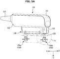
- FIG. 5A is a view illustrating the connector and the connector cover in the ultrasonic probe assembly shown in FIG. 1 .
- FIG. 5B is an enlarged view of A portion in the connector and the connector cover shown in FIG. 5A .
- the connector 110 and the connector cover 140 may be coupled along a second direction Y.
- the coupling device 150 may be disposed in the case 141.
- the coupling device 150 may include a body 151, a guide 152, and a fastening portion 153.
- the body 151 may include the fastening portion 153 coupled the the connector protrusion 132 protruding from the connector 110 in the first direction X.
- the fastening portion 153 may be formed at one end of the body 151. That is, the fastening portion 153 may be formed on the upper portion of the body 151.
- the fastening portion 153 may be formed in a shape corresponding to the connector protrusion 132. Accordingly, the fastening portion 153 may be formed in a cylindrical shape in accordance with the connector protrusion 132. However, it is not limited thereto, and the fastening portion 153 may be formed in various shapes as long as capable of being coupled to the connector protrusion 132.
- the connector 110 may be properly coupled to the connector cover 140 through the fastening portion 153.
- the body 151 may be provided in a form in which a center of an upper portion is hollow. This is to make a weight of a lower portion heavier than the upper portion. That is, it is to secure a sense of stability by placing the center of gravity at the bottom. However, it is not limited thereto and the body 151 may be provided in a form in which a middle of the upper portion is filled.
- the fastening portions 153 may be provided in a number corresponding to the connector protrusion 132. Accordingly, the fastening portion 153 may be formed in plural corresponding to the connector protrusion 132. However, it is not limited thereto, and a single fastening portion 153 may be provided as long as capable of being coupled to the connector protrusion 132.
- the body 151 may further include the guide 152.
- the guide 152 may be provided in an upper portion of the body 151, which is coupled to the connector protrusion 132, and inclined upwardly toward the case 141 along the second direction Y. That is, the guide 152 may include a slope in a region adjacent to the fastening portion 153.
- a rotating shaft 156 may be easily rotated by the guide 152, and in response to rotation of the body 151, the body 151 may be coupled to the connector protrusion 132. Therefore, by the guide 152, it is possible to easily couple the connector protrusion 132 to the body 151 without using a material having high elasticity.
- the coupling device 150 may further include the rotating shaft 156.
- the rotating shaft 156 may be connected to the case 141 and the body 151, respectively.
- the rotating shaft 156 may be rotatably coupled to the case 141 to allow the body 151 to be moved along the first direction X. That is, as the connector 110 is coupled to the connector cover 140 in the second direction Y, the connector protrusion 132 moves the body 151 in the first direction X toward the case 141, and thus the body 151 may be rotated by the rotating shaft 156.
- the body 151 may be moved from the connector protrusion 132 to the case 141 of the connector cover 140.
- the connector protrusion and the body may be easily coupled to each other without using a material having high elasticity.
- the rotating shaft 156 may be a fixed shaft extending in the first direction X in relation to a hook to be described later.
- the rotating shaft 156 may be provided in the first coupling device 150a and the second coupling device 150b, respectively. Accordingly, both the first coupling device 150a and the second coupling device 150b may be rotated. That is, as for the first coupling device 150a and the second coupling device 150b, the body 151 may be moved from the connector protrusion 132 to the case 141 of the connector cover 140, respectively.
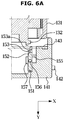
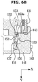
- FIG. 6 is a view illustrating a coupling process of the connector and the connector cover shown in FIG. 5A .
- the fastening portion 153 may include a fastening hole 153a.
- the fastening hole 153a may pass through an upper portion of the body 151 along the first direction X. That is, the fastening hole 153 may allow the connector protrusion 132 to be coupled to the fastening portion 153.
- a shape of the fastening hole 153a may extend in a cylindrical shape in accordance with the shape of the connector protrusion 132. However, it is not limited thereto, and the fastening hole 153a may include various shapes configured to be coupled to the connector protrusion 132.
- the connector cover 140 may further include an elastic member 155.
- the elastic member 155 may be provided between the case 141 and the coupling device 150 to elastically press the body 151 toward the connector protrusion 132. That is, in response to coupling, the connector protrusion 132 may press the coupling device 150 in the first direction X and the elastic member 155 may press the body 151 to a direction opposite to a direction in which the connector protrusion 132 presses, by the elastic force of the elastic member 155. Accordingly, after the connector 110 and the connector cover 140 are coupled to each other, the body 151 may return to a position that is before the coupling begins.
- the elastic member 155 may include a spring. Due to the elastic member 155, the body 151 may return to its original position that is before and after rotation.
- the elastic member 155 may be provided between the first coupling device 150a and the case 141 to press the first coupling device 150a.
- the elastic member 155 may be provided between the second coupling device 150b and the case 141 to press the second coupling device 150b. That is, one or more elastic members 155 may be provided.
- the drawing illustrates that the elastic member 155 pushes the upper portion of the body 151, but is not limited thereto. Therefore, the elastic member 155 may be arranged at a different location as long as allowing the body 151 to expand in the second direction Y after the completion of the coupling and separation.
- the connector cover 140 may further include the push rod 142. This will be described later.
- the coupling device 150 may further include a frame member 157.
- the frame member 157 is formed smaller than the body 151 and may be attached to the body 151.
- the frame member 157 may be disposed closer to the inside of the case 141 than the body 151.
- the frame member 157 may add a weight in the opposite direction of rotation in response to the coupling, thereby allowing the body 151 to return to an initial state after being rotated in the first direction X.
- the frame member 157 may be provided in the first coupling device 150a and the second coupling device 150b, respectively.
- the frame member 157 may be integrally formed with the body 151. However, it is not limited thereto and the frame member 157 and the body 151 may be separately formed and coupled to each other.
- the coupling starts. At this time, the connector protrusion 132 is adjacent to the guide 152 of the coupling device 150.
- the body 151 in response to contact between the connector protrusion 132 and the guide 152, the body 151 may be moved in the first direction X by the rotating shaft 156. In response to the movement of the body 151 in the first direction X, the elastic member 155 is compressed. The elastic member 155 may be compressed until the connector protrusion 132 is coupled to the fastening portion 153.
- the elastic member 155 may press the body 151 toward the inside of the case 141, and due to the weight of the frame member 157, the body 151 may be disposed at the same position as before the coupling.
- the case 141 of the connector 110 is in contact with the packing member 143 of the connector cover 140 to prevent a liquid from entering.
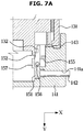
- FIG. 7 is a view illustrating a separation process of the connector and the connector cover shown in FIG. 5A .
- the connector cover 140 may further include a case hole 141a and the push rod 142.
- the case hole 141a may be formed in a lower portion of the case 141 along the first direction X.
- the case hole 141a may be provided to allow the push rod 142 to push the body 151 of the coupling device 150 and thus the case hole 141a may be provided at one end or other end of the case 141. That is, more than one case hole 141a may be provided in accordance with the number of coupling devices 150.
- the case hole 141a may be formed in a cylindrical shape. However, it is not limited thereto, and the case hole 141a may be formed in various shapes as long as corresponding to the shape of the push rod 142.
- the push rod 142 may be provided to move the body 151 in the first direction X through the case hole 141a to separate the coupling device 150 from the connector 110.
- the push rod 142 may push the lower portion of the body 151 to separate the fastening portion 153 from the connector protrusion 132.
- the push rod 142 may be formed in a cylindrical shape, but is not limited thereto. Therefore, the push rod 142 may include various shapes as long as corresponding to the shape of the case hole 141a. Because the push rod 142 is provided in accordance with the number of the case holes 141a, and thus more than one push rod 142 may be provided.
- the connector 110 and the connector cover 140 may be easily separated through the case hole 141a and the push rod 142.
- a user can push the push rod 142 toward the body 151 of the coupling device 150 in the first direction X.
- the push rod 142 may push a position opposite to the position of the fastening portion 153 of the body 151. That is, the push rod 142 may push the lower portion corresponding to the other end of the body 151.
- the body 151 may be rotated by the rotating shaft 156 along the first direction X, and the connector protrusion 132 and the fastening portion 153 may be separated.
- the elastic member 155 is compressed.
- a user can make each component apart from each other toward the second direction Y, thereby completely separating each component.
- the body 151 of the coupling device 150 may return to the same position as the position at the time of coupling by the elastic force of the elastic member 155.
- FIG. 8 is a view illustrating a coupling device in an ultrasonic probe assembly according to another embodiment of the disclosure.
- a body 151 of a coupling device 150 may further include a fastening groove 153b.
- the fastening groove 153b may be formed in an upper portion of the body 151 along a first direction X. That is, the fastening groove 153b may allow a connector protrusion 132 to be coupled to a fastening portion 153.
- a shape of the fastening groove 153b may extend in a cylindrical shape in accordance with the shape of the connector protrusion 132. However, it is not limited thereto, and the fastening groove 153b may include various shapes configured to be coupled to the connector protrusion 132.
- the coupling device 150 may further include a hook 154 coupled to the connector protrusion 132 and a fixed shaft 156a.
- the hook 154 may include hook portions 158a and 158b formed at one end of the hook 154 and configured to prevent the hook 154 from being separated from the connector protrusion 132. At one end of the hook 154, the hook portions 158a and 158b may be fastened with the connector protrusion 132. The other end of the hook 154 may be rotatably coupled to the fixed shaft 156a.
- the fixed shaft 156a may extend in the first direction X and coupled to the case 141 of the connector cover 140.
- More than one hook 154 may be provided to be coupled to the connector protrusion 132 provided in plurality.
- the hook 154 may include a first hook 154a and a second hook 154b.
- the first hook 154a may be coupled to a first protrusion 132a
- the second hook 154b may be coupled to a second protrusion 132b.
- the first hook 154a may include the first hook portion 158a
- the second hook 154b may include the second hook portion 158b.
- the connector protrusion 132 and the coupling device 150 may be firmly coupled to each other. That is, the connector 110 and the connector cover 140 may be coupled to each other.
- the drawing illustrates two hooks 154, but is not limited thereto. Therefore, one or more than three hooks may be provided as long as capable of firmly being coupled to the connector protrusion 132.
Landscapes
- Health & Medical Sciences (AREA)
- Life Sciences & Earth Sciences (AREA)
- Surgery (AREA)
- Veterinary Medicine (AREA)
- Public Health (AREA)
- General Health & Medical Sciences (AREA)
- Animal Behavior & Ethology (AREA)
- Engineering & Computer Science (AREA)
- Medical Informatics (AREA)
- Heart & Thoracic Surgery (AREA)
- Molecular Biology (AREA)
- Biomedical Technology (AREA)
- Nuclear Medicine, Radiotherapy & Molecular Imaging (AREA)
- Physics & Mathematics (AREA)
- Radiology & Medical Imaging (AREA)
- Pathology (AREA)
- Biophysics (AREA)
- Epidemiology (AREA)
- Computer Networks & Wireless Communication (AREA)
- Ultra Sonic Daignosis Equipment (AREA)
Abstract
Description
- This application is based on and claims priority under 35 U.S.C. §119 to Korean Patent Application No.
10-2020-0009792, filed on January 28 2020 - The disclosure relates to an ultrasonic probe assembly, and more particularly, to a cover of an ultrasonic probe connector.
- As there is a growing interest in the importance of sterilization according to the risk of infection in hospitals, the issues relate to the sterilization of medical device emerge. Representative sterilization equipment used for ultrasonic medical devices is a low-temperature plasma sterilizer that converts hydrogen peroxide into plasma and sterilizes the medical devices. After sterilization, hydrogen peroxide is vaporized into water, and thus it has the advantage that it is safe and does not harm the human body. Therefore, the low-temperature plasma sterilizer is widely used for sterilizing an ultrasonic probe. Recently, regulations and laws of the sterilization method for reusable medical devices have expanded, and thus there is a growing need of developing products compatibility with sterilization and disinfection.
- If the low-temperature plasma sterilizer is used frequently, the life of the ultrasonic probe may be shortened due to corrosion of the printed circuit board and the connector of the ultrasonic probe exposed to hydrogen peroxide.
- It is an aspect of the disclosure to provide a connector cover and an ultrasonic probe assembly capable of preventing corrosion and damage of a printed circuit board and an ultrasonic probe connector by a sterilizer.
- It is another aspect of the disclosure to provide a connector cover and an ultrasonic probe assembly having improved product reliability according to corrosion and damage prevention.
- It is another aspect of the disclosure to provide a connector cover capable of being easily coupled to an ultrasonic probe connector.
- Additional aspects of the disclosure will be set forth in part in the description which follows and, in part, will be obvious from the description, or may be learned by practice of the disclosure.
- In accordance with an aspect of the disclosure, a connector cover configured to be used in an ultrasonic probe connector includes a case, and a coupling device disposed at one end portion in the case and configured to be coupled to the connector. The coupling device includes a body including a fastening portion configured to be coupled to a connector protrusion provided to protrude from the connector toward a first direction, and a rotating shaft connected to the case and the body, and the connector cover is configured to be coupled to the connector along a second direction.
- The rotating shaft may be rotatably coupled to the case to allow the body to be moved in the first direction.
- The body may further include a guide formed in one end portion of the body coupled to the connector protrusion and inclined upward in the second direction, and the body may be rotated by the rotating shaft to allow the fastening portion to be coupled to the connector protrusion.
- The coupling device may further include an elastic member provided between the case and the coupling device and configured to elastically press the body toward the connector protrusion.
- The fastening portion may be a first fastening portion, the connector protrusion may be a first protrusion, the body may further include a second fastening portion, the first fastening portion and the second fastening portion may be spaced apart from each other, the first fastening portion may be configured to be coupled to the first protrusion, and the second fastening portion may be configured to be coupled to a second protrusion provided to protrude from the connector toward the first direction.
- The coupling device may be a first coupling device, and the coupling device may further include a second coupling device disposed at the other end of the case and configured to be coupled to the connector.
- The fastening portion may include a fastening hole and a fastening groove provided on an upper portion of the body to be coupled to the connector protrusion.
- The connector cover may further include a case hole provided to pass through the case along the first direction, and a push rod configured to move the body toward the first direction through the case hole so as to separate the coupling device and the connector.
- The fastening portion may be formed on the upper portion of the body, and the push rod may be configured to push a lower portion of the body with respect to the rotating shaft.
- The fastening portion may include a hook configured to be coupled to the connector protrusion, and the rotating shaft may extend in the first direction and then connected to the case and the body.
- In accordance with another aspect of the disclosure, a connector cover configured to be used in an ultrasonic probe connector includes a case, and a coupling device disposed at one side in the case and configured to be coupled to the connector. The coupling device includes a body including a hook configured to be coupled to a connector protrusion provided to protrude from the connector along a first direction, and a fixed shaft provided to extend in the first direction to be connected to the case and the body, and the connector cover is configured to be coupled to the connector along a second direction.
- The hook may be a first hook, the connector protrusion may be a first protrusion, the body may further include a second hook, the first hook and the second hook may be spaced apart from each other, the first hook may be configured to be coupled to the first protrusion, and the second hook may be configured to be coupled to a second protrusion provided to protrude from the connector toward the first direction.
- The coupling device may be a first coupling device, and the coupling device may further include a second coupling device disposed at the other end of the case and configured to be coupled to the connector.
- In accordance with another aspect of the disclosure, an ultrasonic probe assembly includes an ultrasonic probe, a connector connected to the ultrasonic probe, and a connector cover configured to be used in the connector. The connector includes a connector protrusion provided to protrude from the connector along a first direction to be coupled to a medical device. The connector cover includes a case, and a coupling device disposed at one end portion in the case and configured to be coupled to the connector. The coupling device includes a body including a fastening portion configured to be coupled to the connector protrusion, and a rotating shaft connected to the case and the body, and the connector and the connector cover are coupled to each other along a second direction.
- The rotating shaft may be rotatably coupled to the case to allow the body to be moved in the first direction.
- The body may further include a guide formed in one end portion of the body coupled to the connector protrusion and inclined upward in the second direction, and the body may be rotated by the rotating shaft to allow the fastening portion to be coupled to the connector protrusion.
- The coupling device may further include an elastic member provided between the case and the coupling device and configured to elastically press the body toward the connector protrusion.
- The connector protrusion may be a first protrusion, the connector may further include a second protrusion formed to be spaced apart from the first protrusion and provided to protrude along the first direction, the fastening portion may be a first fastening portion configured to be coupled to the first protrusion, and the body may further include a second fastening portion formed to be spaced apart from the first fastening portion and configured to be coupled to the second protrusion.
- The ultrasonic probe assembly may further include a case hole provided to pass through the case along the first direction, and a push rod configured to move the body toward the first direction through the case hole so as to separate the coupling device and the connector.
- The fastening portion may be formed on an upper portion of the body, and the push rod may be configured to push a lower portion of the body with respect to the rotating shaft.
- These and/or other aspects of the disclosure will become apparent and more readily appreciated from the following description of embodiments, taken in conjunction with the accompanying drawings of which:
-
FIG. 1 is a view illustrating a medical device and an ultrasonic probe assembly according to an embodiment of the disclosure; -
FIG. 2 is a view illustrating a connector in the ultrasonic probe assembly shown inFIG. 1 ; -
FIG. 3 is a view illustrating a bottom of the connector in the ultrasonic probe assembly shown inFIG. 1 ; -
FIG. 4 is a view illustrating a connector cover in the ultrasonic probe assembly shown inFIG. 1 ; -
FIG. 5A is a view illustrating the connector and the connector cover in the ultrasonic probe assembly shown inFIG. 1 ; -
FIG. 5B is an enlarged view of A portion in the connector and the connector cover shown inFIG. 5A ; -
FIG. 6 is a view illustrating a coupling process of the connector and the connector cover shown inFIG. 5A ; -
FIG. 7 is a view illustrating a separation process of the connector and the connector cover shown inFIG. 5A ; and -
FIG. 8 is a view illustrating a coupling device in an ultrasonic probe assembly according to another embodiment of the disclosure. - Embodiments described in the disclosure and configurations shown in the drawings are merely examples of the embodiments of the disclosure, and may be modified in various different ways at the time of filing of the present application to replace the embodiments and drawings of the disclosure.
- In addition, the same reference numerals or signs shown in the drawings of the disclosure indicate elements or components performing substantially the same function.
- Also, the terms used herein are used to describe the embodiments and are not intended to limit and / or restrict the disclosure. The singular forms "a," "an" and "the" are intended to include the plural forms as well, unless the context clearly indicates otherwise. In this disclosure, the terms "including", "having", and the like are used to specify features, numbers, steps, operations, elements, components, or combinations thereof, but do not preclude the presence or addition of one or more of the features, elements, steps, operations, elements, components, or combinations thereof.
- It will be understood that, although the terms first, second, third, etc., may be used herein to describe various elements, but elements are not limited by these terms. These terms are only used to distinguish one element from another element. For example, without departing from the scope of the disclosure, a first element may be termed as a second element, and a second element may be termed as a first element. The term of "and / or" includes a plurality of combinations of relevant items or any one item among a plurality of relevant items.
- In the following detailed description, the terms of "front side", "rear side", "left side", "right side", and the like may be defined by the drawings, but the shape and the location of the component is not limited by the term.
- Particularly, as shown in
FIG. 2 , a direction of a connector to which a cable is not connected is defined as a front side, and a direction of the connector to which the cable is connected is defined a rear side. Left and right sides and upper and lower sides are defined based on this. - The disclosure will be described more fully hereinafter with reference to the accompanying drawings
-
FIG. 1 is a view illustrating a medical device and an ultrasonic probe assembly according to an embodiment of the disclosure. - Referring to
FIG. 1 , amedical device 1 according to an embodiment may include amain body 10 and anultrasonic probe 100 configured to transmit an ultrasound signal to an object to be diagnosed and receive a signal reflected from the object. Theultrasonic probe 100 may be connected to themain body 10 by acable 120. - The
ultrasonic probe 100 may be mounted on themain body 10 by a holder 22. When themedical device 1 is not in use, an examiner may mount theultrasonic probe 100 to the holder 22 and store theultrasonic probe 100.FIG. 1 illustrates that the holder 22, to which theultrasonic probe 100 is mounted, is provided on acontrol panel 20, but the holder 22 may be provided on themain body 10 according to the user's convenience. Alternatively, the holder 22 may be provided on both themain body 10 and thecontrol panel 20. - A moving
device 12 may be provided in themain body 10 to move themedical device 1. The movingdevice 12 may be a plurality of casters provided on a bottom surface of themain body 10. The casters may be configured to be aligned to move themain body 10 to a specific direction, configured to be freely movable so as be movable to any direction, and configured to be locked to be stopped at a specific location. - The
ultrasonic probe 100 may include an ultrasonic transmitter and receiver provided in a housing. The ultrasonic transmitter and receiver may include a transducer module (not shown) configured to irradiate ultrasonic waves to an object, receive echo ultrasonic waves reflected from the object, and interconvert electrical signals and ultrasonic waves. Themedical device 1 may include amale connector 110 configured to transmit and receive a signal to and from themain body 10 by being physically coupled to afemale connector 14 of themain body 10, and thecable 120 configured to connect themale connector 110 to the transducer module (not shown). Themale connector 110 may be referred to as aconnector 110. - The object may be a living body of a human or an animal, or tissue in vivo such as blood vessels, bones, muscles, etc., but is not limited thereto. Therefore, the object may be an object as long as its internal structure can be imaged by the
medical device 1. - The ultrasonic probe assembly may include the
ultrasonic probe 100, thecable 120, theconnector 110, and aconnector cover 140 to be described later. - A
display 30 and thecontrol panel 20 may be provided on themain body 10 of themedical device 1. Aninputter 24 configured to allow a user to control themedical device 1 may be provided on thecontrol panel 20. Theinputter 24 may receive not only setting information, but also various control commands on theultrasonic probe 100 from a user. - An
auxiliary display 26 may be provided on thecontrol panel 20. Theauxiliary display 26 may provide related information such as a menu for optimizing an ultrasound image or an auxiliary image, or may provide a graphic interface to a user. -
FIG. 2 is a view illustrating a connector in the ultrasonic probe assembly shown inFIG. 1 .FIG. 3 is a view illustrating a bottom of the connector in the ultrasonic probe assembly shown inFIG. 1 . - Referring to
FIGS. 2 and3 , theconnector 110 may include the housing and aconnection device 130. - The housing may include an
upper housing 111, aside housing 112, and aconnection housing 113. Theupper housing 111 may be positioned in an upper portion of theconnector 110 to form an upper surface and a front surface of theconnector 110. Theside housing 112 may form a left side and a right side of theconnector 110. Theconnection housing 113 may form an exterior of a region connected to thecable 120. Accordingly, theconnection housing 113 may be connected to thecable 120. Thecable 120 may receive or supply a signal from or to theconnector 110 that is connected. - The
connection device 130 may be provided in a lower portion of theconnector 110. Theconnection device 130 may include acase 131, aconnection terminal 132, and acircuit board 133. Thecase 131 may form an outer surface of theconnection device 130 to form an exterior of theconnection device 130. - The
connection terminal 132 may protrude from an inside to an outside of theconnector 110 in a first direction X. Theconnection terminal 132 may be referred to as aconnector protrusion 132. Theconnector protrusion 132 may be configured to be connected to the main body of the medical device. However, it is not limited thereto, and theconnector protrusion 132 may not be connected to themain body 10 of themedical device 1 but be connected to theconnector cover 140 to be described later. Theconnector protrusion 132 may be provided in plural as shown, but is not limited thereto. Therefore, a single connector protrusion may be provided. - Because the
connector cover 140 is coupled with theconnector 110 through theconnection terminal 132 of theconnector 110 used for themedical device 1 that is theconnector protrusion 132, it is possible to reduce additional manufacturing and component costs. - The
connector protrusion 132 may include afirst protrusion 132a, asecond protrusion 132b, athird protrusion 132c, and afourth protrusion 132d. - The
first protrusion 132a and thesecond protrusion 132b may be provided at one end of theconnection device 130 and coupled to afirst coupling device 150a to be described later. Thethird protrusion 132c and thefourth protrusion 132d may be provided at the other end of theconnection device 130 and coupled to asecond coupling device 150b to be described later. - The
first protrusion 132a and thesecond protrusion 132b may be provided adjacent to the front surface of theconnector 110. Thethird protrusion 132c and thefourth protrusion 132d may be provided adjacent to the rear surface of theconnector 110. - The
circuit board 133 may be provided in the inside of theconnection device 130. Thecircuit board 133 may be connected to the main body of the medical device to transmit signals, which are transmitted and received by the ultrasonic probe, to the medical device. - The
connection terminal 132 may further include a connectingportion 134. The connectingportion 134 may be configured to be coupled to themain body 10 of themedical device 1. Accordingly, the connectingportion 134 may be formed in a shape corresponding to themain body 10. -
FIG. 4 is a view illustrating a connector cover in the ultrasonic probe assembly shown inFIG. 1 . - Referring to
FIG. 4 , theconnector cover 140 may include acase 141, apush rod 142, a packingmember 143, and acoupling device 150. - The
case 141 may be formed on the outside of theconnector cover 140 to surround a portion coupled to theconnector 110. Thecase 141 may be formed in a rectangular parallelepiped shape. However, it is not limited thereto and may be formed in various shapes such as a regular tetrahedron. - The packing
member 143 may seal a space between theconnector 110 and theconnector cover 140 in response to coupling between theconnector 110 and theconnector cover 140. The packingmember 143 may be formed of silicon. However, it is not limited thereto, and thus the packingmember 143 may be formed of various materials capable of sealing a coupling space between theconnector 110 and theconnector cover 140. The packingmember 143 may be provided in a shape corresponding to the coupling region between theconnector 110 and theconnector cover 140. - The
coupling device 150 may include thefirst coupling device 150a and thesecond coupling device 150b. - The
first coupling device 150a may be arranged at one end in thecase 141 and coupled to theconnector 110. That is, at one end in thecase 141, thefirst coupling device 150a may be coupled to thefirst protrusion 132a and thesecond protrusion 132b of theconnector connection device 130. One end of thecase 141 may be a front portion of thecase 141. - The
second coupling device 150b may be disposed at the other end in thecase 141 and coupled to theconnector 110. That is, at the other end in thecase 141, thesecond coupling device 150b may be coupled to thethird protrusion 132c and thefourth protrusion 132d of theconnector connection device 130. The other end of thecase 141 may be a rear portion of thecase 141. - However, it is not limited thereto, and the
first protrusion 132a and thesecond protrusion 132b may be coupled to thesecond coupling device 150b. Thethird protrusion 132c and thefourth protrusion 132d may be coupled to thefirst coupling device 150a. - Because at least one
coupling device 150 is included, theconnector 110 and theconnector cover 140 may be firmly coupled to each other. -
FIG. 5A is a view illustrating the connector and the connector cover in the ultrasonic probe assembly shown inFIG. 1 .FIG. 5B is an enlarged view of A portion in the connector and the connector cover shown inFIG. 5A . - A description will be made based on the
second coupling device 150b. Referring toFIGS 5A and5B , theconnector 110 and theconnector cover 140 may be coupled along a second direction Y. - The
coupling device 150 may be disposed in thecase 141. Thecoupling device 150 may include abody 151, aguide 152, and afastening portion 153. - The
body 151 may include thefastening portion 153 coupled the theconnector protrusion 132 protruding from theconnector 110 in the first direction X. Thefastening portion 153 may be formed at one end of thebody 151. That is, thefastening portion 153 may be formed on the upper portion of thebody 151. Thefastening portion 153 may be formed in a shape corresponding to theconnector protrusion 132. Accordingly, thefastening portion 153 may be formed in a cylindrical shape in accordance with theconnector protrusion 132. However, it is not limited thereto, and thefastening portion 153 may be formed in various shapes as long as capable of being coupled to theconnector protrusion 132. Theconnector 110 may be properly coupled to theconnector cover 140 through thefastening portion 153. - The
body 151 may be provided in a form in which a center of an upper portion is hollow. This is to make a weight of a lower portion heavier than the upper portion. That is, it is to secure a sense of stability by placing the center of gravity at the bottom. However, it is not limited thereto and thebody 151 may be provided in a form in which a middle of the upper portion is filled. - In addition, the
fastening portions 153 may be provided in a number corresponding to theconnector protrusion 132. Accordingly, thefastening portion 153 may be formed in plural corresponding to theconnector protrusion 132. However, it is not limited thereto, and asingle fastening portion 153 may be provided as long as capable of being coupled to theconnector protrusion 132. - The
body 151 may further include theguide 152. Theguide 152 may be provided in an upper portion of thebody 151, which is coupled to theconnector protrusion 132, and inclined upwardly toward thecase 141 along the second direction Y. That is, theguide 152 may include a slope in a region adjacent to thefastening portion 153. - In response to coupling between the
connector 110 and theconnector cover 140 in the second direction Y, arotating shaft 156 may be easily rotated by theguide 152, and in response to rotation of thebody 151, thebody 151 may be coupled to theconnector protrusion 132. Therefore, by theguide 152, it is possible to easily couple theconnector protrusion 132 to thebody 151 without using a material having high elasticity. - The
coupling device 150 may further include therotating shaft 156. Therotating shaft 156 may be connected to thecase 141 and thebody 151, respectively. Therotating shaft 156 may be rotatably coupled to thecase 141 to allow thebody 151 to be moved along the first direction X. That is, as theconnector 110 is coupled to theconnector cover 140 in the second direction Y, theconnector protrusion 132 moves thebody 151 in the first direction X toward thecase 141, and thus thebody 151 may be rotated by therotating shaft 156. Thebody 151 may be moved from theconnector protrusion 132 to thecase 141 of theconnector cover 140. - Because the body is rotated due to the rotating shaft and then coupled to the connector protrusion, the connector protrusion and the body may be easily coupled to each other without using a material having high elasticity.
- The
rotating shaft 156 may be a fixed shaft extending in the first direction X in relation to a hook to be described later. - The
rotating shaft 156 may be provided in thefirst coupling device 150a and thesecond coupling device 150b, respectively. Accordingly, both thefirst coupling device 150a and thesecond coupling device 150b may be rotated. That is, as for thefirst coupling device 150a and thesecond coupling device 150b, thebody 151 may be moved from theconnector protrusion 132 to thecase 141 of theconnector cover 140, respectively. -
FIG. 6 is a view illustrating a coupling process of the connector and the connector cover shown inFIG. 5A . - Referring to
FIG. 6 , thefastening portion 153 may include afastening hole 153a. Thefastening hole 153a may pass through an upper portion of thebody 151 along the first direction X. That is, thefastening hole 153 may allow theconnector protrusion 132 to be coupled to thefastening portion 153. A shape of thefastening hole 153a may extend in a cylindrical shape in accordance with the shape of theconnector protrusion 132. However, it is not limited thereto, and thefastening hole 153a may include various shapes configured to be coupled to theconnector protrusion 132. - The
connector cover 140 may further include anelastic member 155. - The
elastic member 155 may be provided between thecase 141 and thecoupling device 150 to elastically press thebody 151 toward theconnector protrusion 132. That is, in response to coupling, theconnector protrusion 132 may press thecoupling device 150 in the first direction X and theelastic member 155 may press thebody 151 to a direction opposite to a direction in which theconnector protrusion 132 presses, by the elastic force of theelastic member 155. Accordingly, after theconnector 110 and theconnector cover 140 are coupled to each other, thebody 151 may return to a position that is before the coupling begins. Theelastic member 155 may include a spring. Due to theelastic member 155, thebody 151 may return to its original position that is before and after rotation. - The
elastic member 155 may be provided between thefirst coupling device 150a and thecase 141 to press thefirst coupling device 150a. In addition, theelastic member 155 may be provided between thesecond coupling device 150b and thecase 141 to press thesecond coupling device 150b. That is, one or moreelastic members 155 may be provided. - The drawing illustrates that the
elastic member 155 pushes the upper portion of thebody 151, but is not limited thereto. Therefore, theelastic member 155 may be arranged at a different location as long as allowing thebody 151 to expand in the second direction Y after the completion of the coupling and separation. - The
connector cover 140 may further include thepush rod 142. This will be described later. - The
coupling device 150 may further include aframe member 157. - The
frame member 157 is formed smaller than thebody 151 and may be attached to thebody 151. Theframe member 157 may be disposed closer to the inside of thecase 141 than thebody 151. Theframe member 157 may add a weight in the opposite direction of rotation in response to the coupling, thereby allowing thebody 151 to return to an initial state after being rotated in the first direction X. Theframe member 157 may be provided in thefirst coupling device 150a and thesecond coupling device 150b, respectively. Theframe member 157 may be integrally formed with thebody 151. However, it is not limited thereto and theframe member 157 and thebody 151 may be separately formed and coupled to each other. - A coupling process will be described.
- As shown in
FIG. 6A , in response to movement of one or each of theconnector 110 and theconnector cover 140 toward the second direction Y, the coupling starts. At this time, theconnector protrusion 132 is adjacent to theguide 152 of thecoupling device 150. - As shown in
FIG. 6B , in response to contact between theconnector protrusion 132 and theguide 152, thebody 151 may be moved in the first direction X by therotating shaft 156. In response to the movement of thebody 151 in the first direction X, theelastic member 155 is compressed. Theelastic member 155 may be compressed until theconnector protrusion 132 is coupled to thefastening portion 153. - As shown in
FIG. 6C , in response to the completion of the coupling between theconnector protrusion 132 and thefastening portion 153, theelastic member 155 may press thebody 151 toward the inside of thecase 141, and due to the weight of theframe member 157, thebody 151 may be disposed at the same position as before the coupling. At this time, thecase 141 of theconnector 110 is in contact with the packingmember 143 of theconnector cover 140 to prevent a liquid from entering. -
FIG. 7 is a view illustrating a separation process of the connector and the connector cover shown inFIG. 5A . - Referring to
FIG. 7A , theconnector cover 140 may further include acase hole 141a and thepush rod 142. - The
case hole 141a may be formed in a lower portion of thecase 141 along the first direction X. Thecase hole 141a may be provided to allow thepush rod 142 to push thebody 151 of thecoupling device 150 and thus thecase hole 141a may be provided at one end or other end of thecase 141. That is, more than onecase hole 141a may be provided in accordance with the number ofcoupling devices 150. - The
case hole 141a may be formed in a cylindrical shape. However, it is not limited thereto, and thecase hole 141a may be formed in various shapes as long as corresponding to the shape of thepush rod 142. - The
push rod 142 may be provided to move thebody 151 in the first direction X through thecase hole 141a to separate thecoupling device 150 from theconnector 110. Thepush rod 142 may push the lower portion of thebody 151 to separate thefastening portion 153 from theconnector protrusion 132. - The
push rod 142 may be formed in a cylindrical shape, but is not limited thereto. Therefore, thepush rod 142 may include various shapes as long as corresponding to the shape of thecase hole 141a. Because thepush rod 142 is provided in accordance with the number of the case holes 141a, and thus more than onepush rod 142 may be provided. - The
connector 110 and theconnector cover 140 may be easily separated through thecase hole 141a and thepush rod 142. - A separation process will be described.
- A user can push the
push rod 142 toward thebody 151 of thecoupling device 150 in the first direction X. Thepush rod 142 may push a position opposite to the position of thefastening portion 153 of thebody 151. That is, thepush rod 142 may push the lower portion corresponding to the other end of thebody 151. By pushing thepush rod 142, thebody 151 may be rotated by therotating shaft 156 along the first direction X, and theconnector protrusion 132 and thefastening portion 153 may be separated. - Referring to
FIG. 7B , in response to pushing thebody 151 by thepush rod 142 to separate theconnector 110 and theconnector cover 140, theelastic member 155 is compressed. In response to the completion of the separation of theconnector protrusion 132 and thecoupling device 150, a user can make each component apart from each other toward the second direction Y, thereby completely separating each component. After the separation, thebody 151 of thecoupling device 150 may return to the same position as the position at the time of coupling by the elastic force of theelastic member 155. -
FIG. 8 is a view illustrating a coupling device in an ultrasonic probe assembly according to another embodiment of the disclosure. - The description of the basic configuration of the
coupling device 150 has been described above with reference toFIGS. 4 to 7 , and thus the same description will be omitted and only different components will be described. - Referring to
FIG. 8A , abody 151 of acoupling device 150 may further include afastening groove 153b. - The
fastening groove 153b may be formed in an upper portion of thebody 151 along a first direction X. That is, thefastening groove 153b may allow aconnector protrusion 132 to be coupled to afastening portion 153. A shape of thefastening groove 153b may extend in a cylindrical shape in accordance with the shape of theconnector protrusion 132. However, it is not limited thereto, and thefastening groove 153b may include various shapes configured to be coupled to theconnector protrusion 132. - Referring to
FIG. 8B , thecoupling device 150 may further include ahook 154 coupled to theconnector protrusion 132 and a fixedshaft 156a. - The
hook 154 may includehook portions hook 154 and configured to prevent thehook 154 from being separated from theconnector protrusion 132. At one end of thehook 154, thehook portions connector protrusion 132. The other end of thehook 154 may be rotatably coupled to the fixedshaft 156a. - The fixed
shaft 156a may extend in the first direction X and coupled to thecase 141 of theconnector cover 140. - More than one
hook 154 may be provided to be coupled to theconnector protrusion 132 provided in plurality. Thehook 154 may include afirst hook 154a and asecond hook 154b. Thefirst hook 154a may be coupled to afirst protrusion 132a, and thesecond hook 154b may be coupled to asecond protrusion 132b. - The
first hook 154a may include thefirst hook portion 158a, and thesecond hook 154b may include thesecond hook portion 158b. - Due to the
hook 154, theconnector protrusion 132 and thecoupling device 150 may be firmly coupled to each other. That is, theconnector 110 and theconnector cover 140 may be coupled to each other. - The drawing illustrates two
hooks 154, but is not limited thereto. Therefore, one or more than three hooks may be provided as long as capable of firmly being coupled to theconnector protrusion 132. - As is apparent from the above description, it is possible to provide a connector cover and an ultrasonic probe assembly with reduced cost because the conventional connector connection terminal is used.
- It is possible to provide an ultrasonic probe assembly with improved reliability by preventing corrosion and damage by using the connector cover.
- It is possible to provide a connector cover configured to be easily coupled to an ultrasonic probe connector by using a coupling device.
- Although a few embodiments of the disclosure have been shown and described, it would be appreciated by those skilled in the art that changes may be made in these embodiments without departing from the principles and spirit of the disclosure, the scope of which is defined in the claims and their equivalents.
Claims (15)
- A connector cover configured to be used in an ultrasonic probe connector comprising:a case; anda coupling device disposed at one end portion in the case and configured to be coupled to the connector,wherein the coupling device comprisesa body comprising a fastening portion configured to be coupled to a connector protrusion provided to protrude from the connector toward a first direction; anda rotating shaft connected to the case and the body,wherein the connector cover is configured to be coupled to the connector along a second direction.
- The connector cover of claim 1, wherein
the rotating shaft is rotatably coupled to the case to allow the body to be moved in the first direction. - The connector cover of claim 2, wherein
the body further comprises a guide formed in one end portion of the body coupled to the connector protrusion and inclined upward in the second direction,
wherein the body is rotated by the rotating shaft to allow the fastening portion to be coupled to the connector protrusion. - The connector cover of claim 3, wherein
the coupling device further comprises an elastic member provided between the case and the coupling device and configured to elastically press the body toward the connector protrusion. - The connector cover of claim 1, wherein
the fastening portion is a first fastening portion, the connector protrusion is a first protrusion, and the body further comprises a second fastening portion,
wherein the first fastening portion and the second fastening portion are spaced apart from each other,
wherein the first fastening portion is configured to be coupled to the first protrusion, and the second fastening portion is configured to be coupled to a second protrusion provided to protrude from the connector toward the first direction. - The connector cover of claim 1, wherein
the coupling device is a first coupling device, and
the coupling device further comprises a second coupling device disposed at the other end of the case and configured to be coupled to the connector. - The connector cover of claim 1, wherein
the fastening portion comprises a fastening hole and a fastening groove provided on an upper portion of the body to be coupled to the connector protrusion. - The connector cover of claim 2, further comprising:a case hole provided to pass through the case along the first direction; anda push rod configured to move the body toward the first direction through the case hole so as to separate the coupling device and the connector.
- The connector cover of claim 8, wherein
the fastening portion is formed on the upper portion of the body, and
the push rod is configured to push a lower portion of the body with respect to the rotating shaft. - The connector cover of claim 1, wherein:
the fastening portion comprises a hook configured to be coupled to the connector protrusion, and the rotating shaft extends in the first direction and then connected to the case and the body. - An ultrasonic probe assembly comprising the connector cover of claim 1, the ultrasonic probe assembly comprising:the ultrasonic probe; anda connector connected to the ultrasonic probe,wherein the connector protrusion provided to be coupled to a medical device.
- The ultrasonic probe assembly of claim 11, wherein
the rotating shaft is rotatably coupled to the case to allow the body to be moved in the first direction. - The ultrasonic probe assembly of claim 12, wherein
the body further comprises a guide formed in one end portion of the body coupled to the connector protrusion and inclined upward in the second direction,
wherein the body is rotated by the rotating shaft to allow the fastening portion to be coupled to the connector protrusion. - The ultrasonic probe assembly of claim 13, wherein
the coupling device further comprises an elastic member provided between the case and the coupling device and configured to elastically press the body toward the connector protrusion. - The ultrasonic probe assembly of claim 11, wherein
the connector protrusion is a first protrusion, and the connector further comprises a second protrusion formed to be spaced apart from the first protrusion and provided to protrude along the first direction,
wherein the fastening portion is a first fastening portion configured to be coupled to the first protrusion, and the body further comprises a second fastening portion formed to be spaced apart from the first fastening portion and configured to be coupled to the second protrusion.
Applications Claiming Priority (1)
| Application Number | Priority Date | Filing Date | Title |
|---|---|---|---|
| KR1020200009792A KR102854967B1 (en) | 2020-01-28 | 2020-01-28 | Connector cover and ultrasonic probe assembly having the same |
Publications (2)
| Publication Number | Publication Date |
|---|---|
| EP3858246A1 true EP3858246A1 (en) | 2021-08-04 |
| EP3858246B1 EP3858246B1 (en) | 2023-03-08 |
Family
ID=74205647
Family Applications (1)
| Application Number | Title | Priority Date | Filing Date |
|---|---|---|---|
| EP21152773.4A Active EP3858246B1 (en) | 2020-01-28 | 2021-01-21 | Connector cover and ultrasonic probe assembly having the same |
Country Status (4)
| Country | Link |
|---|---|
| US (1) | US11502452B2 (en) |
| EP (1) | EP3858246B1 (en) |
| KR (1) | KR102854967B1 (en) |
| CN (1) | CN113258321B (en) |
Citations (3)
| Publication number | Priority date | Publication date | Assignee | Title |
|---|---|---|---|---|
| US20040063348A1 (en) * | 2002-06-25 | 2004-04-01 | Jenkinson Philip James | Method and apparatus for control of appliance coupler retention and withdrawal forces |
| US7481664B1 (en) * | 2008-06-12 | 2009-01-27 | Tyco Electronics Corporation | Electrical connector assembly |
| KR20200009792A (en) | 2018-07-20 | 2020-01-30 | 넥센타이어 주식회사 | Rubber composition and Tire comprising rubber composition |
Family Cites Families (30)
| Publication number | Priority date | Publication date | Assignee | Title |
|---|---|---|---|---|
| JPH05285133A (en) | 1992-04-10 | 1993-11-02 | Toshiba Corp | Waterproof structure for ultrasonic probe and waterproof cover for the probe |
| JP2000340290A (en) * | 1999-05-31 | 2000-12-08 | Olympus Optical Co Ltd | Connector device |
| US6685491B2 (en) * | 2001-03-15 | 2004-02-03 | Frank Gergek | Combined connector for fluid and electrical connection |
| ITGE20010032U1 (en) * | 2001-11-28 | 2003-05-28 | Ariete Spa | SAFETY DEVICE FOR THE POWER SUPPLY OF ELECTRICAL APPLIANCES. |
| JP3782755B2 (en) * | 2002-05-16 | 2006-06-07 | アロカ株式会社 | Ultrasonic probe connector |
| AU2003204838B2 (en) * | 2002-06-25 | 2009-01-08 | Resmed Limited | Method and Apparatus for Control of Appliance Coupler Retention and Withdrawal Forces |
| US7059877B2 (en) * | 2004-07-07 | 2006-06-13 | Clements National Company | Latch mechanism for electrical connector |
| JP4575087B2 (en) * | 2004-08-30 | 2010-11-04 | オリンパス株式会社 | Waterproof cap for ultrasonic endoscope |
| JP4745840B2 (en) * | 2006-01-30 | 2011-08-10 | Hoya株式会社 | Ultrasonic signal connector for ultrasonic endoscope |
| JP2007325609A (en) * | 2006-06-06 | 2007-12-20 | Pentax Corp | Waterproof cap for ultrasonic signal connector of ultrasonic endoscope |
| JP4806666B2 (en) * | 2007-08-17 | 2011-11-02 | 日立アロカメディカル株式会社 | Ultrasonic probe |
| KR101377581B1 (en) * | 2008-02-05 | 2014-03-25 | 히로세덴끼 가부시끼가이샤 | Electric connector for flat conductor |
| JP5152221B2 (en) * | 2010-02-19 | 2013-02-27 | 第一精工株式会社 | Electrical connector and electrical connector assembly |
| JP5471890B2 (en) * | 2010-06-28 | 2014-04-16 | 住友電装株式会社 | Charging connector |
| US8834190B2 (en) * | 2011-08-12 | 2014-09-16 | Fci Americas Technology Llc | Electrical connector with latch |
| JP5684083B2 (en) | 2011-09-29 | 2015-03-11 | ジーイー・メディカル・システムズ・グローバル・テクノロジー・カンパニー・エルエルシー | Probe cover, ultrasonic probe, and ultrasonic image display device |
| DE102012102188B4 (en) * | 2012-03-15 | 2017-07-27 | Phoenix Contact Gmbh & Co. Kg | Connector and method for mounting a connector |
| JP5985249B2 (en) * | 2012-05-17 | 2016-09-06 | 矢崎総業株式会社 | Board connector |
| CN104662744B (en) * | 2012-07-20 | 2017-08-18 | 阿西斯特医疗系统有限公司 | For protecting the not contaminated connector cover piece of connection |
| KR101406551B1 (en) | 2013-04-05 | 2014-06-11 | 인제대학교 산학협력단 | Ultrasound probe cover |
| EP3028346A1 (en) * | 2013-07-31 | 2016-06-08 | 3M Innovative Properties Company | Board mount electrical connector assembly |
| KR101482996B1 (en) | 2014-10-24 | 2015-01-21 | 이다운 | sterile ultrasound probe cover and sterile cover packing method |
| EP3240485B1 (en) | 2014-12-29 | 2025-04-09 | Civco Medical Instruments Co., Inc. | Sterile covers for ultrasound probe |
| KR102445161B1 (en) * | 2015-01-20 | 2022-09-21 | 삼성메디슨 주식회사 | Probe, ultrasound imaging apparatus and controlling method of the ultrasound imaging apparatus |
| CN204538347U (en) * | 2015-02-12 | 2015-08-05 | 无锡祥生医学影像有限责任公司 | The connector connection locking structure of convenient plug |
| CN105990751B (en) * | 2015-02-12 | 2018-05-11 | 无锡祥生医疗科技股份有限公司 | The connector connection locking structure of convenient plug |
| KR20160105669A (en) * | 2015-02-27 | 2016-09-07 | 삼성전자주식회사 | Connecter Module and Locking Device including the same |
| CN206685563U (en) * | 2016-07-13 | 2017-11-28 | 番禺得意精密电子工业有限公司 | Bayonet connector |
| JP6897265B2 (en) | 2017-04-17 | 2021-06-30 | ニプロ株式会社 | Cover for ultrasonic diagnostic equipment, ultrasonic diagnostic equipment with cover, and bracket for ultrasonic diagnostic equipment |
| US10218097B2 (en) * | 2017-07-11 | 2019-02-26 | Te Connectivity Corporation | Card edge connector assembly |
-
2020
- 2020-01-28 KR KR1020200009792A patent/KR102854967B1/en active Active
-
2021
- 2021-01-19 US US17/151,769 patent/US11502452B2/en active Active
- 2021-01-21 EP EP21152773.4A patent/EP3858246B1/en active Active
- 2021-01-28 CN CN202110117112.5A patent/CN113258321B/en active Active
Patent Citations (3)
| Publication number | Priority date | Publication date | Assignee | Title |
|---|---|---|---|---|
| US20040063348A1 (en) * | 2002-06-25 | 2004-04-01 | Jenkinson Philip James | Method and apparatus for control of appliance coupler retention and withdrawal forces |
| US7481664B1 (en) * | 2008-06-12 | 2009-01-27 | Tyco Electronics Corporation | Electrical connector assembly |
| KR20200009792A (en) | 2018-07-20 | 2020-01-30 | 넥센타이어 주식회사 | Rubber composition and Tire comprising rubber composition |
Also Published As
| Publication number | Publication date |
|---|---|
| US20210234306A1 (en) | 2021-07-29 |
| CN113258321B (en) | 2025-10-28 |
| EP3858246B1 (en) | 2023-03-08 |
| CN113258321A (en) | 2021-08-13 |
| KR20210096396A (en) | 2021-08-05 |
| KR102854967B1 (en) | 2025-09-04 |
| US11502452B2 (en) | 2022-11-15 |
Similar Documents
| Publication | Publication Date | Title |
|---|---|---|
| US8461978B2 (en) | Wireless ultrasound probe asset tracking | |
| EP2164399B1 (en) | Wireless ultrasound probe cable | |
| CN101742968B (en) | Wireless ultrasound probe user interface | |
| US20100160784A1 (en) | Wireless Ultrasound Probe With Audible Indicator | |
| US5846097A (en) | Submersible connector system | |
| US20100168576A1 (en) | Light Weight Wireless Ultrasound Probe | |
| JP6465835B2 (en) | Medical diagnostic imaging Ultrasonic probe Battery pack Communication equipment | |
| WO1997013300A9 (en) | Submersible connector system | |
| WO2008146208A2 (en) | Wireless ultrasound probe with energy conservation | |
| US12201475B2 (en) | Ultrasound probe | |
| EP3335637A1 (en) | Ultrasonic probe | |
| KR20160089615A (en) | Probe, ultrasound imaging apparatus and controlling method of the ultrasound imaging apparatus | |
| KR102530174B1 (en) | Ultrasound imaging apparatus and control method for the same | |
| EP3858246B1 (en) | Connector cover and ultrasonic probe assembly having the same | |
| WO2008146207A2 (en) | Wireless ultrasound probe with heads-up display | |
| WO2008146209A1 (en) | Wireless ultrasound probe with voice control | |
| US20190343483A1 (en) | Systems, methods, and apparatuses for fluid ingress detection for ultrasound transducers | |
| EP2243429A1 (en) | Ultrasonic diagnostic apparatus | |
| WO2008146202A1 (en) | Wireless ultrasound probe antennas | |
| CN222777368U (en) | Sterile cover installation detection device and surgical robot | |
| KR101587247B1 (en) | Connector of Ultrasound Transducer and Connecting Structure of System for Accommodating the same |
Legal Events
| Date | Code | Title | Description |
|---|---|---|---|
| PUAI | Public reference made under article 153(3) epc to a published international application that has entered the european phase |
Free format text: ORIGINAL CODE: 0009012 |
|
| STAA | Information on the status of an ep patent application or granted ep patent |
Free format text: STATUS: THE APPLICATION HAS BEEN PUBLISHED |
|
| AK | Designated contracting states |
Kind code of ref document: A1 Designated state(s): AL AT BE BG CH CY CZ DE DK EE ES FI FR GB GR HR HU IE IS IT LI LT LU LV MC MK MT NL NO PL PT RO RS SE SI SK SM TR |
|
| STAA | Information on the status of an ep patent application or granted ep patent |
Free format text: STATUS: REQUEST FOR EXAMINATION WAS MADE |
|
| 17P | Request for examination filed |
Effective date: 20210930 |
|
| RBV | Designated contracting states (corrected) |
Designated state(s): AL AT BE BG CH CY CZ DE DK EE ES FI FR GB GR HR HU IE IS IT LI LT LU LV MC MK MT NL NO PL PT RO RS SE SI SK SM TR |
|
| RIC1 | Information provided on ipc code assigned before grant |
Ipc: A61B 1/00 20060101ALN20220809BHEP Ipc: H01R 13/46 20060101ALI20220809BHEP Ipc: A61B 8/00 20060101AFI20220809BHEP |
|
| GRAP | Despatch of communication of intention to grant a patent |
Free format text: ORIGINAL CODE: EPIDOSNIGR1 |
|
| STAA | Information on the status of an ep patent application or granted ep patent |
Free format text: STATUS: GRANT OF PATENT IS INTENDED |
|
| RIC1 | Information provided on ipc code assigned before grant |
Ipc: A61B 1/00 20060101ALN20220913BHEP Ipc: H01R 13/46 20060101ALI20220913BHEP Ipc: A61B 8/00 20060101AFI20220913BHEP |
|
| INTG | Intention to grant announced |
Effective date: 20220926 |
|
| GRAS | Grant fee paid |
Free format text: ORIGINAL CODE: EPIDOSNIGR3 |
|
| GRAA | (expected) grant |
Free format text: ORIGINAL CODE: 0009210 |
|
| STAA | Information on the status of an ep patent application or granted ep patent |
Free format text: STATUS: THE PATENT HAS BEEN GRANTED |
|
| AK | Designated contracting states |
Kind code of ref document: B1 Designated state(s): AL AT BE BG CH CY CZ DE DK EE ES FI FR GB GR HR HU IE IS IT LI LT LU LV MC MK MT NL NO PL PT RO RS SE SI SK SM TR |
|
| REG | Reference to a national code |
Ref country code: CH Ref legal event code: EP Ref country code: AT Ref legal event code: REF Ref document number: 1552037 Country of ref document: AT Kind code of ref document: T Effective date: 20230315 |
|
| REG | Reference to a national code |
Ref country code: DE Ref legal event code: R096 Ref document number: 602021001532 Country of ref document: DE |
|
| REG | Reference to a national code |
Ref country code: IE Ref legal event code: FG4D |
|
| REG | Reference to a national code |
Ref country code: LT Ref legal event code: MG9D |
|
| REG | Reference to a national code |
Ref country code: NL Ref legal event code: MP Effective date: 20230308 |
|
| PG25 | Lapsed in a contracting state [announced via postgrant information from national office to epo] |
Ref country code: RS Free format text: LAPSE BECAUSE OF FAILURE TO SUBMIT A TRANSLATION OF THE DESCRIPTION OR TO PAY THE FEE WITHIN THE PRESCRIBED TIME-LIMIT Effective date: 20230308 Ref country code: NO Free format text: LAPSE BECAUSE OF FAILURE TO SUBMIT A TRANSLATION OF THE DESCRIPTION OR TO PAY THE FEE WITHIN THE PRESCRIBED TIME-LIMIT Effective date: 20230608 Ref country code: LV Free format text: LAPSE BECAUSE OF FAILURE TO SUBMIT A TRANSLATION OF THE DESCRIPTION OR TO PAY THE FEE WITHIN THE PRESCRIBED TIME-LIMIT Effective date: 20230308 Ref country code: LT Free format text: LAPSE BECAUSE OF FAILURE TO SUBMIT A TRANSLATION OF THE DESCRIPTION OR TO PAY THE FEE WITHIN THE PRESCRIBED TIME-LIMIT Effective date: 20230308 Ref country code: HR Free format text: LAPSE BECAUSE OF FAILURE TO SUBMIT A TRANSLATION OF THE DESCRIPTION OR TO PAY THE FEE WITHIN THE PRESCRIBED TIME-LIMIT Effective date: 20230308 Ref country code: ES Free format text: LAPSE BECAUSE OF FAILURE TO SUBMIT A TRANSLATION OF THE DESCRIPTION OR TO PAY THE FEE WITHIN THE PRESCRIBED TIME-LIMIT Effective date: 20230308 |
|
| REG | Reference to a national code |
Ref country code: AT Ref legal event code: MK05 Ref document number: 1552037 Country of ref document: AT Kind code of ref document: T Effective date: 20230308 |
|
| PG25 | Lapsed in a contracting state [announced via postgrant information from national office to epo] |
Ref country code: SE Free format text: LAPSE BECAUSE OF FAILURE TO SUBMIT A TRANSLATION OF THE DESCRIPTION OR TO PAY THE FEE WITHIN THE PRESCRIBED TIME-LIMIT Effective date: 20230308 Ref country code: NL Free format text: LAPSE BECAUSE OF FAILURE TO SUBMIT A TRANSLATION OF THE DESCRIPTION OR TO PAY THE FEE WITHIN THE PRESCRIBED TIME-LIMIT Effective date: 20230308 Ref country code: GR Free format text: LAPSE BECAUSE OF FAILURE TO SUBMIT A TRANSLATION OF THE DESCRIPTION OR TO PAY THE FEE WITHIN THE PRESCRIBED TIME-LIMIT Effective date: 20230609 Ref country code: FI Free format text: LAPSE BECAUSE OF FAILURE TO SUBMIT A TRANSLATION OF THE DESCRIPTION OR TO PAY THE FEE WITHIN THE PRESCRIBED TIME-LIMIT Effective date: 20230308 |
|
| PG25 | Lapsed in a contracting state [announced via postgrant information from national office to epo] |
Ref country code: SM Free format text: LAPSE BECAUSE OF FAILURE TO SUBMIT A TRANSLATION OF THE DESCRIPTION OR TO PAY THE FEE WITHIN THE PRESCRIBED TIME-LIMIT Effective date: 20230308 Ref country code: RO Free format text: LAPSE BECAUSE OF FAILURE TO SUBMIT A TRANSLATION OF THE DESCRIPTION OR TO PAY THE FEE WITHIN THE PRESCRIBED TIME-LIMIT Effective date: 20230308 Ref country code: PT Free format text: LAPSE BECAUSE OF FAILURE TO SUBMIT A TRANSLATION OF THE DESCRIPTION OR TO PAY THE FEE WITHIN THE PRESCRIBED TIME-LIMIT Effective date: 20230710 Ref country code: EE Free format text: LAPSE BECAUSE OF FAILURE TO SUBMIT A TRANSLATION OF THE DESCRIPTION OR TO PAY THE FEE WITHIN THE PRESCRIBED TIME-LIMIT Effective date: 20230308 Ref country code: CZ Free format text: LAPSE BECAUSE OF FAILURE TO SUBMIT A TRANSLATION OF THE DESCRIPTION OR TO PAY THE FEE WITHIN THE PRESCRIBED TIME-LIMIT Effective date: 20230308 Ref country code: AT Free format text: LAPSE BECAUSE OF FAILURE TO SUBMIT A TRANSLATION OF THE DESCRIPTION OR TO PAY THE FEE WITHIN THE PRESCRIBED TIME-LIMIT Effective date: 20230308 |
|
| PG25 | Lapsed in a contracting state [announced via postgrant information from national office to epo] |
Ref country code: SK Free format text: LAPSE BECAUSE OF FAILURE TO SUBMIT A TRANSLATION OF THE DESCRIPTION OR TO PAY THE FEE WITHIN THE PRESCRIBED TIME-LIMIT Effective date: 20230308 Ref country code: PL Free format text: LAPSE BECAUSE OF FAILURE TO SUBMIT A TRANSLATION OF THE DESCRIPTION OR TO PAY THE FEE WITHIN THE PRESCRIBED TIME-LIMIT Effective date: 20230308 Ref country code: IS Free format text: LAPSE BECAUSE OF FAILURE TO SUBMIT A TRANSLATION OF THE DESCRIPTION OR TO PAY THE FEE WITHIN THE PRESCRIBED TIME-LIMIT Effective date: 20230708 |
|
| REG | Reference to a national code |
Ref country code: DE Ref legal event code: R097 Ref document number: 602021001532 Country of ref document: DE |
|
| PLBE | No opposition filed within time limit |
Free format text: ORIGINAL CODE: 0009261 |
|
| STAA | Information on the status of an ep patent application or granted ep patent |
Free format text: STATUS: NO OPPOSITION FILED WITHIN TIME LIMIT |
|
| PG25 | Lapsed in a contracting state [announced via postgrant information from national office to epo] |
Ref country code: SI Free format text: LAPSE BECAUSE OF FAILURE TO SUBMIT A TRANSLATION OF THE DESCRIPTION OR TO PAY THE FEE WITHIN THE PRESCRIBED TIME-LIMIT Effective date: 20230308 Ref country code: DK Free format text: LAPSE BECAUSE OF FAILURE TO SUBMIT A TRANSLATION OF THE DESCRIPTION OR TO PAY THE FEE WITHIN THE PRESCRIBED TIME-LIMIT Effective date: 20230308 |
|
| 26N | No opposition filed |
Effective date: 20231211 |
|
| PG25 | Lapsed in a contracting state [announced via postgrant information from national office to epo] |
Ref country code: MC Free format text: LAPSE BECAUSE OF FAILURE TO SUBMIT A TRANSLATION OF THE DESCRIPTION OR TO PAY THE FEE WITHIN THE PRESCRIBED TIME-LIMIT Effective date: 20230308 |
|
| PG25 | Lapsed in a contracting state [announced via postgrant information from national office to epo] |
Ref country code: MC Free format text: LAPSE BECAUSE OF FAILURE TO SUBMIT A TRANSLATION OF THE DESCRIPTION OR TO PAY THE FEE WITHIN THE PRESCRIBED TIME-LIMIT Effective date: 20230308 |
|
| REG | Reference to a national code |
Ref country code: CH Ref legal event code: PL |
|
| PG25 | Lapsed in a contracting state [announced via postgrant information from national office to epo] |
Ref country code: LU Free format text: LAPSE BECAUSE OF NON-PAYMENT OF DUE FEES Effective date: 20240121 |
|
| PG25 | Lapsed in a contracting state [announced via postgrant information from national office to epo] |
Ref country code: LU Free format text: LAPSE BECAUSE OF NON-PAYMENT OF DUE FEES Effective date: 20240121 |
|
| PG25 | Lapsed in a contracting state [announced via postgrant information from national office to epo] |
Ref country code: BE Free format text: LAPSE BECAUSE OF NON-PAYMENT OF DUE FEES Effective date: 20240131 |
|
| PG25 | Lapsed in a contracting state [announced via postgrant information from national office to epo] |
Ref country code: CH Free format text: LAPSE BECAUSE OF NON-PAYMENT OF DUE FEES Effective date: 20240131 |
|
| PG25 | Lapsed in a contracting state [announced via postgrant information from national office to epo] |
Ref country code: CH Free format text: LAPSE BECAUSE OF NON-PAYMENT OF DUE FEES Effective date: 20240131 Ref country code: BE Free format text: LAPSE BECAUSE OF NON-PAYMENT OF DUE FEES Effective date: 20240131 |
|
| REG | Reference to a national code |
Ref country code: BE Ref legal event code: MM Effective date: 20240131 |
|
| PG25 | Lapsed in a contracting state [announced via postgrant information from national office to epo] |
Ref country code: BG Free format text: LAPSE BECAUSE OF FAILURE TO SUBMIT A TRANSLATION OF THE DESCRIPTION OR TO PAY THE FEE WITHIN THE PRESCRIBED TIME-LIMIT Effective date: 20230308 |
|
| PG25 | Lapsed in a contracting state [announced via postgrant information from national office to epo] |
Ref country code: BG Free format text: LAPSE BECAUSE OF FAILURE TO SUBMIT A TRANSLATION OF THE DESCRIPTION OR TO PAY THE FEE WITHIN THE PRESCRIBED TIME-LIMIT Effective date: 20230308 |
|
| PG25 | Lapsed in a contracting state [announced via postgrant information from national office to epo] |
Ref country code: IE Free format text: LAPSE BECAUSE OF NON-PAYMENT OF DUE FEES Effective date: 20240121 |
|
| PG25 | Lapsed in a contracting state [announced via postgrant information from national office to epo] |
Ref country code: IE Free format text: LAPSE BECAUSE OF NON-PAYMENT OF DUE FEES Effective date: 20240121 |
|
| PG25 | Lapsed in a contracting state [announced via postgrant information from national office to epo] |
Ref country code: CY Free format text: LAPSE BECAUSE OF FAILURE TO SUBMIT A TRANSLATION OF THE DESCRIPTION OR TO PAY THE FEE WITHIN THE PRESCRIBED TIME-LIMIT; INVALID AB INITIO Effective date: 20210121 |
|
| PG25 | Lapsed in a contracting state [announced via postgrant information from national office to epo] |
Ref country code: HU Free format text: LAPSE BECAUSE OF FAILURE TO SUBMIT A TRANSLATION OF THE DESCRIPTION OR TO PAY THE FEE WITHIN THE PRESCRIBED TIME-LIMIT; INVALID AB INITIO Effective date: 20210121 |
|
| GBPC | Gb: european patent ceased through non-payment of renewal fee |
Effective date: 20250121 |
|
| PG25 | Lapsed in a contracting state [announced via postgrant information from national office to epo] |
Ref country code: GB Free format text: LAPSE BECAUSE OF NON-PAYMENT OF DUE FEES Effective date: 20250121 |
|
| PG25 | Lapsed in a contracting state [announced via postgrant information from national office to epo] |
Ref country code: TR Free format text: LAPSE BECAUSE OF FAILURE TO SUBMIT A TRANSLATION OF THE DESCRIPTION OR TO PAY THE FEE WITHIN THE PRESCRIBED TIME-LIMIT Effective date: 20230308 |
|
| PGFP | Annual fee paid to national office [announced via postgrant information from national office to epo] |
Ref country code: FR Payment date: 20251209 Year of fee payment: 6 |
|
| PGFP | Annual fee paid to national office [announced via postgrant information from national office to epo] |
Ref country code: DE Payment date: 20251208 Year of fee payment: 6 |
|
| PGFP | Annual fee paid to national office [announced via postgrant information from national office to epo] |
Ref country code: IT Payment date: 20251209 Year of fee payment: 6 |