EP3858216A1 - Endoscope - Google Patents
Endoscope Download PDFInfo
- Publication number
- EP3858216A1 EP3858216A1 EP19866520.0A EP19866520A EP3858216A1 EP 3858216 A1 EP3858216 A1 EP 3858216A1 EP 19866520 A EP19866520 A EP 19866520A EP 3858216 A1 EP3858216 A1 EP 3858216A1
- Authority
- EP
- European Patent Office
- Prior art keywords
- switch
- cable
- operation switch
- endoscope according
- disposed
- Prior art date
- Legal status (The legal status is an assumption and is not a legal conclusion. Google has not performed a legal analysis and makes no representation as to the accuracy of the status listed.)
- Granted
Links
Images




Classifications
-
- A—HUMAN NECESSITIES
- A61—MEDICAL OR VETERINARY SCIENCE; HYGIENE
- A61B—DIAGNOSIS; SURGERY; IDENTIFICATION
- A61B1/00—Instruments for performing medical examinations of the interior of cavities or tubes of the body by visual or photographical inspection, e.g. endoscopes; Illuminating arrangements therefor
- A61B1/04—Instruments for performing medical examinations of the interior of cavities or tubes of the body by visual or photographical inspection, e.g. endoscopes; Illuminating arrangements therefor combined with photographic or television appliances
- A61B1/05—Instruments for performing medical examinations of the interior of cavities or tubes of the body by visual or photographical inspection, e.g. endoscopes; Illuminating arrangements therefor combined with photographic or television appliances characterised by the image sensor, e.g. camera, being in the distal end portion
-
- A—HUMAN NECESSITIES
- A61—MEDICAL OR VETERINARY SCIENCE; HYGIENE
- A61B—DIAGNOSIS; SURGERY; IDENTIFICATION
- A61B1/00—Instruments for performing medical examinations of the interior of cavities or tubes of the body by visual or photographical inspection, e.g. endoscopes; Illuminating arrangements therefor
- A61B1/00002—Operational features of endoscopes
- A61B1/00004—Operational features of endoscopes characterised by electronic signal processing
- A61B1/00006—Operational features of endoscopes characterised by electronic signal processing of control signals
-
- A—HUMAN NECESSITIES
- A61—MEDICAL OR VETERINARY SCIENCE; HYGIENE
- A61B—DIAGNOSIS; SURGERY; IDENTIFICATION
- A61B1/00—Instruments for performing medical examinations of the interior of cavities or tubes of the body by visual or photographical inspection, e.g. endoscopes; Illuminating arrangements therefor
- A61B1/00002—Operational features of endoscopes
- A61B1/00004—Operational features of endoscopes characterised by electronic signal processing
- A61B1/00009—Operational features of endoscopes characterised by electronic signal processing of image signals during a use of endoscope
-
- A—HUMAN NECESSITIES
- A61—MEDICAL OR VETERINARY SCIENCE; HYGIENE
- A61B—DIAGNOSIS; SURGERY; IDENTIFICATION
- A61B1/00—Instruments for performing medical examinations of the interior of cavities or tubes of the body by visual or photographical inspection, e.g. endoscopes; Illuminating arrangements therefor
- A61B1/00002—Operational features of endoscopes
- A61B1/00039—Operational features of endoscopes provided with input arrangements for the user
- A61B1/00042—Operational features of endoscopes provided with input arrangements for the user for mechanical operation
-
- A—HUMAN NECESSITIES
- A61—MEDICAL OR VETERINARY SCIENCE; HYGIENE
- A61B—DIAGNOSIS; SURGERY; IDENTIFICATION
- A61B1/00—Instruments for performing medical examinations of the interior of cavities or tubes of the body by visual or photographical inspection, e.g. endoscopes; Illuminating arrangements therefor
- A61B1/00064—Constructional details of the endoscope body
- A61B1/00071—Insertion part of the endoscope body
-
- A—HUMAN NECESSITIES
- A61—MEDICAL OR VETERINARY SCIENCE; HYGIENE
- A61B—DIAGNOSIS; SURGERY; IDENTIFICATION
- A61B1/00—Instruments for performing medical examinations of the interior of cavities or tubes of the body by visual or photographical inspection, e.g. endoscopes; Illuminating arrangements therefor
- A61B1/005—Flexible endoscopes
- A61B1/0051—Flexible endoscopes with controlled bending of insertion part
-
- G—PHYSICS
- G02—OPTICS
- G02B—OPTICAL ELEMENTS, SYSTEMS OR APPARATUS
- G02B23/00—Telescopes, e.g. binoculars; Periscopes; Instruments for viewing the inside of hollow bodies; Viewfinders; Optical aiming or sighting devices
- G02B23/24—Instruments or systems for viewing the inside of hollow bodies, e.g. fibrescopes
Definitions
- the present invention relates to an endoscope, and relates particularly to an endoscope comprising an operation switch for performing various settings in endoscopic surgery.
- a rigid endoscope is configured to comprise an elongated rigid insertion part which is inserted into a body cavity, a grip part which is connected to a proximal end portion of the insertion part, and a flexible cable, of which a proximal end portion is connected to the insertion part via the grip part.
- JP2007-196017A discloses such a rigid endoscope in which a switch arranged part is provided in a grip part.
- the switch arranged part comprises a plurality of remote switches for remotely controlling a video recording device, such as a video tape recorder, a camera control unit, or the like.
- JP2009-233173A discloses a rigid endoscope in which a remote control unit is provided in the middle of a camera cable. A plurality of push switches are provided in this remote control unit.
- an endoscope for example, a colonoscope, a gastroscope, or the like
- an autoclave device for the rigid endoscope is a device that performs sterilization processing on the endoscope using high-temperature and high-pressure air, and performs sterilization processing by exposing the endoscope, for example, under an environment where saturated water vapor is at 2 atm and at 121°C, for approximately 20 minutes.
- the temperature, atmospheric pressure, and time set in the autoclave device are examples.
- the endoscope Since the endoscope is exposed to a high-pressure environment at the time of sterilization processing by the autoclave device, the endoscope comprises an airtight structure that seals a gap between components configuring the endoscope such that water vapor does not infiltrate into devices of the endoscope from the gap.
- the rigid endoscope comprising an operation switch requires an airtight structure that seals a gap around the operation switch.
- JP2018-075461A discloses an endoscope comprising a switch unit having an airtight structure.
- the switch unit comprises a frame body, which is fixed to an opening portion and in which a plurality of holes are formed, a plurality of switches which are provided in two holes respectively among the plurality of holes, a flexible switch cover which covers the plurality of switches, a first locking part which is formed on the switch cover at a position between the plurality of switches, a switch fixing member, which fixes the plurality of switches, that are arranged in the two holes respectively and are covered with the switch cover, to the opening portion, and to which the first locking part is locked at a position facing the first locking part, and a second locking part which is formed on an outer periphery of the switch cover and is locked to the frame body.
- the present invention is devised in view of such circumstances, and an object thereof is to provide an endoscope in which an operation switch included in the endoscope can be sealed with an airtight structure having a simple structure.
- an endoscope comprising a rigid insertion part that is inserted into a body, a flexible cable that is connected to a proximal end side of the insertion part, and an operation switch that is disposed in the cable.
- the cable has a skin covering an outer periphery of the cable, and the skin defines an airtight space inside the cable.
- the operation switch is disposed in the airtight space.
- the operation switch comprises a push member at a position facing a surface of the skin on an airtight space side.
- a base member to which the operation switch is attached is provided in the airtight space.
- the base member has an insertion port at each of a distal end portion on an insertion part side and a proximal end portion on an opposite side to the insertion part side.
- the base member has a recessed portion accommodating the operation switch.
- a plate-shaped body having a surface area larger than the push member is disposed between the push member and the surface of the skin on the airtight space side.
- a tubular cover rubber mounted on an outer peripheral portion of the cable is further included, an elastically deformable button portion is formed on an outer surface of the cover rubber in a protruding manner, and the cover rubber is mounted on the cable in a state where the button portion faces the operation switch.
- an elastically deformable button portion is formed on the skin in a protruding manner, and the operation switch is disposed in the airtight space in a state of facing the button portion.
- a plurality of the operation switches are disposed in the cable.
- the operation switch is an image switching switch, an image immobilizing switch, an imaging switch, a zoom switch, a washing switch, a light amount adjusting switch, or a sensitivity adjusting switch.
- the operation switch is a tactile switch.
- the operation switch is a membrane switch.
- the operation switch included in the endoscope can be sealed with the airtight structure having a simple structure.
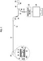
- Fig. 1 is an overall view of an endoscope 10 according to the embodiment.
- the endoscope 10 illustrated in Fig. 1 is a rigid endoscope such as a laparoscope, and is inserted into a body cavity to observe the inside of the body cavity.
- the endoscope 10 comprises an elongated rigid insertion part 12 that is inserted into the body cavity, an L-shaped grip part 14 connected to a proximal end portion of the insertion part 12, a flexible cable 16 connected to a proximal end side of the insertion part 12 via the grip part 14, and a switch disposed part 18 provided in a middle portion of the cable 16.
- a connector device 20 is provided at a proximal end portion of the cable 16, and a processor device 22 and a light source device 24 are attachably and detachably connected to the endoscope 10 via the connector device 20.
- a monitor 26 is connected to the processor device 22.
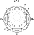
- Fig. 2 is a front view of a distal end portion of the insertion part 12.
- Fig. 1 illustrates an enlarged cross section of main parts at the distal end portion of the insertion part 12.
- an observation part 28 is provided on a distal end surface 12A of the insertion part 12.
- the observation part 28 comprises an observation window 30, an emission end 32A that is a distal end portion of a light guide 32, which is disposed around the observation window 30, an image pickup lens group 34 and a prism 36 that are disposed at a rear part of the observation window 30, and a solid-state imaging element 38.
- a solid-state imaging element 38 a charge coupled device (CCD) image sensor or a complementary metal oxide semiconductor (CMOS) image sensor can be used.
- CCD charge coupled device
- CMOS complementary metal oxide semiconductor
- a proximal end portion of the light guide 32 is connected to a light guide rod 40 of the connector device 20 by being inserted into the insertion part 12, the grip part 14, and the cable 16, and is connected to the light source device 24 via the light guide rod 40. Accordingly, illumination light radiated from the light source device 24 is transmitted via the light guide 32, and is radiated to the front of the insertion part 12 from three emission ends 32A of the light guide 32. Consequently, the inside of the body cavity of a patient is illuminated.
- subject light picked up from the observation window 30 is formed as an image on an imaging surface of the solid-state imaging element 38 via the image pickup lens group 34 and the prism 36, and is converted to an image pickup signal by the solid-state imaging element 38.
- a distal end portion of a signal line 42 is connected to the solid-state imaging element 38 via a base substrate (not illustrated).
- a proximal end portion of the signal line 42 is connected to the connector device 20 by being inserted into the insertion part 12, the grip part 14, and the cable 16. Then, the signal line 42 is accommodated in a video cable 44 of the connector device 20, and is connected to a connector 46 linked to a distal end portion of the video cable 44.
- the processor device 22 causes the monitor 26 to display an endoscopic image based on the image pickup signal input by the solid-state imaging element 38.
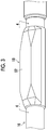
- Fig. 3 is an enlarged perspective view of the switch disposed part 18 disposed in the middle portion of the cable 16.
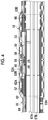
- Fig. 4 is a cross-sectional view of the switch disposed part 18 taken along line 4-4 of Fig. 3 .
- Fig. 5 is a perspective view of an operation switch 50 disposed at the switch disposed part 18, and illustrates an external shape of the operation switch 50 in a case where a skin 52 covering an outer periphery of the cable 16 is removed.
- Fig. 6 is a cross-sectional view taken along line 6-6 of Fig. 5 .
- the switch disposed part 18 of the embodiment is configured by disposing the operation switch 50 and wiring (not illustrated) connected to the operation switch 50 in an airtight space 17 inside the cable 16, which is defined by the skin 52, as illustrated in Fig. 4 .
- the operation switch 50 is configured to be operable through pressing via the skin 52 from the outside of the cable 16.
- the airtightness of the airtight space 17 inside the cable 16 is usually defined through the following configuration. That is, the skin 52 is configured as one tubular member having no boundary in the middle. A gap between a distal end portion of the skin 52 and a proximal end portion of the grip part 14 is filled and sealed with an adhesive. In addition, a gap between the proximal end portion of the cable 16 and a distal end portion of the connector device 20 is filled and sealed with an adhesive. Airtightness is defined by such a configuration of the skin 52 and an adhesive filling structure.
- the endoscope 10 of embodiment has adopted a configuration where the operation switch 50 is disposed in the airtight space 17 inside the cable 16, of which airtightness is defined by the skin 52, it is not necessary to add an airtight structure, which is dedicated to the operation switch 50, to the operation switch 50, and accordingly, the operation switch 50 can be sealed with an airtight structure having a simple structure. Accordingly, since the structure of the operation switch 50 is simplified and the weight of the endoscope 10 is reduced, the operability of the endoscope 10 improves.
- the tactile switch is a switch that comprises a base 54 connected to a foundation 53, a fixed contact 56 fixed to the base 54, a dome-shaped movable contact 58, and a push member 60, and operates an operated part as the push member 60 is pressed to bring the movable contact 58 into contact with the fixed contact 56.
- the base 54 of the tactile switch is attached to a base member 62 via the foundation 53.
- the base member 62 is provided in the airtight space 17.
- the base member 62 is configured in a tubular shape, has an insertion port 63A at a distal end portion on an insertion part 12 (refer to Fig. 1 ) side, and has an insertion port 63B at a proximal end portion on an opposite side to the insertion part 12 side.
- a proximal end portion of a tube 64 arranged in the airtight space 17 is inserted and fixed to the insertion port 63A of the base member 62, and a distal end portion of a spiral tube 66 arranged in the airtight space 17 is inserted and fixed to the insertion port 63B of the base member 62.
- the tactile switch can be stably disposed in the airtight space 17.
- An embodiment of fixing the tube 64 to the insertion port 63A and an embodiment of fixing the spiral tube 66 to the insertion port 63B are not particularly limited, and for example, a fastening member such as a screw and a bolt, can be exemplified.
- a tactile switch (model number: SKSWCFE010 or SKSWCFE010) manufactured by Alps Alpine or a tactile switch (model number: EVPAWCD4A or EVPAWBD4A) manufactured by Panasonic can be exemplified as a tactile switch to be mounted.
- the base member 62 is configured in a tubular shape in the embodiment, without being limited thereto, the base member may be in a shape of having at least the insertion ports 63A and 63B.
- a distal end ring part comprising the insertion port 63A and a proximal end ring part comprising the insertion port 63B are connected by a plate-shaped connecting member may be adopted.
- a heat-stretchable silicone tube can be applied as the skin 52.
- the convex switch disposed part 18 to which the shape of the base member 62 is transferred is configured in the middle portion of the cable 16 as in Fig. 3 .
- a position where the push member 60 is disposed in a circumferential direction of the skin 52 is not particularly limited, in a case where a surgeon holds the grip part 14 and directs the insertion part 12 toward the front of the surgeon, the insertion part is disposed at a position facing the surgeon in the embodiment.
- the push member 60 of the tactile switch is attached with the push member protruding from an outer surface 62A of the base member 62, the push member 60 is pressed by the skin 52 in some cases where the skin 52 has thermally contracted. Therefore, in the endoscope 10 of embodiment, a recessed portion 62B is formed in the base member 62, the tactile switch is accommodated in the recessed portion 62B, and the push member 60 is disposed so as not to protrude from the outer surface of the base member 62. Accordingly, the push member 60 can be effectively operated.
- the size of each of components configuring the tactile switch is also small.
- a member having a small size for example, a disk having a diameter of 1 mm
- the push member 60 can be indirectly pressed via the plate 68, it is easy to press the push member 60.
- the plate 68 in a case where the plate 68 is disposed, it is preferable to make a gap between the plate 68 and the surface 52A as small as possible. Accordingly, since a deformation amount of the surface 52A that deforms in a case of pressing the skin 52 can be made small, burden on the surface 52A can be alleviated.
- a plate-shaped body made of a metal having high stiffness is preferable as the plate 68, a plate-shaped body made of a resin may be used insofar as stiffness can be ensured.
- the shape of the plate 68 may be circular, or may be another shape.
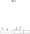
- Fig. 7 is an explanatory view in which a cover rubber 70 is mounted on an outer peripheral portion of the cable 16 illustrated in Fig. 3 .
- Fig. 8 is a cross-sectional view of the switch disposed part 18 including the cover rubber 70.
- the cover rubber 70 illustrated in Figs. 7 and 8 is configured in a tubular shape and is elastically mounted on the outer peripheral portion of the cable 16, in which the switch disposed part 18 is positioned.
- an elastically deformable button portion 72 is formed in a protruding manner.
- the cover rubber 70 is mounted on the cable 16 in a state where the button portion 72 faces the operation switch 50.
- the following effects can be obtained.
- cover rubber 70 comprising the button portion 72 is mounted on the outer peripheral portion of the cable 16 in the example
- a structure, in which an elastically deformable button portion 73 is formed in a protruding manner on the skin 52 positioned at the switch disposed part 18, and the operation switch 50 faces the button portion 73 may be adopted as illustrated in a cross-sectional view of the switch disposed part 18 of Fig. 9 . Accordingly, it is possible to instantly and easily learn the position of the operation switch 50 without using the cover rubber 70.
- an image switching switch that switches, as an image to be displayed on the monitor 26, between a normal captured image and a special light image (for example, a white light (WL) image, a blue laser imaging (BLI) image, a linked color imaging (LCI) image, or a hypoxia imaging image) can be exemplified.
- a special light image for example, a white light (WL) image, a blue laser imaging (BLI) image, a linked color imaging (LCI) image, or a hypoxia imaging image
- an image immobilizing switch an imaging switch, a zoom switch comprising a telephoto and wide-angle buttons, a scope distal end washing switch, a light amount adjusting switch comprising large and small buttons, a sensitivity adjusting switch comprising high and low buttons, or the like can be exemplified.
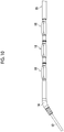
- a plurality of (three in Fig. 10 ) switch disposed parts 18 may be disposed on the cable 16.
- an image switching switch can be assigned as one of the operation switches 50
- light intensity switches can be assigned as two of the operation switches 50 and 50.
- the plurality of switch disposed parts 18 illustrated in Fig. 10 are disposed along a longitudinal direction of the cable 16, the switch disposed parts may be disposed along a circumferential direction of the cable 16.
- the operation switch 50 is not limited to the tactile switch, and for example, a membrane switch comprising a push member may be adopted. Since the tactile switch and the membrane switch realize a clicking sensation with a switch alone, a switch operating sensation can be given to a surgeon even in a case where the operation switch 50 is invisible.
- the operation switch 50 is disposed at a position within a range where operation is possible in a state where the grip part 14 is held such that a surgeon holding the grip part 14 easily operates.
- the operation switch 50 it is preferable to dispose the operation switch 50 at a position within a range where the operation switch can be operated by the middle finger or the little finger.
- the endoscope 10 of the embodiment in combination with an endoscopic surgical device (for example, refer to JP2017-080437A ) which is used by being inserted into one mantle tube together with an endoscopic treatment tool such as high-frequency forceps.
- an endoscopic surgical device for example, refer to JP2017-080437A
Landscapes
- Health & Medical Sciences (AREA)
- Life Sciences & Earth Sciences (AREA)
- Surgery (AREA)
- Engineering & Computer Science (AREA)
- Physics & Mathematics (AREA)
- Optics & Photonics (AREA)
- Medical Informatics (AREA)
- General Health & Medical Sciences (AREA)
- Pathology (AREA)
- Nuclear Medicine, Radiotherapy & Molecular Imaging (AREA)
- Biomedical Technology (AREA)
- Heart & Thoracic Surgery (AREA)
- Biophysics (AREA)
- Molecular Biology (AREA)
- Animal Behavior & Ethology (AREA)
- Radiology & Medical Imaging (AREA)
- Public Health (AREA)
- Veterinary Medicine (AREA)
- Signal Processing (AREA)
- Mechanical Engineering (AREA)
- Astronomy & Astrophysics (AREA)
- General Physics & Mathematics (AREA)
- Endoscopes (AREA)
- Instruments For Viewing The Inside Of Hollow Bodies (AREA)
Abstract
Description
- The present invention relates to an endoscope, and relates particularly to an endoscope comprising an operation switch for performing various settings in endoscopic surgery.
- In recent years, since invasion to a patient is small compared to surgery in which a laparotomy, a thoracotomy, or the like is performed, endoscopic surgery using endoscopes (rigid endoscopes), such as a laparoscope, is widely performed. A rigid endoscope is configured to comprise an elongated rigid insertion part which is inserted into a body cavity, a grip part which is connected to a proximal end portion of the insertion part, and a flexible cable, of which a proximal end portion is connected to the insertion part via the grip part.
-
JP2007-196017A - In addition,
JP2009-233173A - However, an endoscope (for example, a colonoscope, a gastroscope, or the like) is washed and disinfected after being used. In particular, an autoclave device for the rigid endoscope is a device that performs sterilization processing on the endoscope using high-temperature and high-pressure air, and performs sterilization processing by exposing the endoscope, for example, under an environment where saturated water vapor is at 2 atm and at 121°C, for approximately 20 minutes. The temperature, atmospheric pressure, and time set in the autoclave device are examples.
- Since the endoscope is exposed to a high-pressure environment at the time of sterilization processing by the autoclave device, the endoscope comprises an airtight structure that seals a gap between components configuring the endoscope such that water vapor does not infiltrate into devices of the endoscope from the gap. In addition, even the rigid endoscope comprising an operation switch requires an airtight structure that seals a gap around the operation switch.
-
JP2018-075461A - However, in a case where an airtight structure having a complicated structure as disclosed in
JP2018-075461A - The present invention is devised in view of such circumstances, and an object thereof is to provide an endoscope in which an operation switch included in the endoscope can be sealed with an airtight structure having a simple structure.
- According to an aspect of the present invention, in order to achieve the object of the present invention, there is provided an endoscope comprising a rigid insertion part that is inserted into a body, a flexible cable that is connected to a proximal end side of the insertion part, and an operation switch that is disposed in the cable. The cable has a skin covering an outer periphery of the cable, and the skin defines an airtight space inside the cable. The operation switch is disposed in the airtight space.
- According to the aspect of the present invention, it is preferable that the operation switch comprises a push member at a position facing a surface of the skin on an airtight space side.
- According to the aspect of the present invention, it is preferable that a base member to which the operation switch is attached is provided in the airtight space.
- According to the aspect of the present invention, it is preferable that the base member has an insertion port at each of a distal end portion on an insertion part side and a proximal end portion on an opposite side to the insertion part side.
- According to the aspect of the present invention, it is preferable that the base member has a recessed portion accommodating the operation switch.
- According to the aspect of the present invention, it is preferable that a plate-shaped body having a surface area larger than the push member is disposed between the push member and the surface of the skin on the airtight space side.
- According to the aspect of the present invention, it is preferable that a tubular cover rubber mounted on an outer peripheral portion of the cable is further included, an elastically deformable button portion is formed on an outer surface of the cover rubber in a protruding manner, and the cover rubber is mounted on the cable in a state where the button portion faces the operation switch.
- According to the aspect of the present invention, it is preferable that an elastically deformable button portion is formed on the skin in a protruding manner, and the operation switch is disposed in the airtight space in a state of facing the button portion.
- According to the aspect of the present invention, it is preferable that a plurality of the operation switches are disposed in the cable.
- According to the aspect of the present invention, it is preferable that the operation switch is an image switching switch, an image immobilizing switch, an imaging switch, a zoom switch, a washing switch, a light amount adjusting switch, or a sensitivity adjusting switch.
- According to the aspect of the present invention, it is preferable that the operation switch is a tactile switch.
- According to the aspect of the present invention, it is preferable that the operation switch is a membrane switch.
- With the present invention, the operation switch included in the endoscope can be sealed with the airtight structure having a simple structure.
-
-
Fig. 1 is a schematic configuration view of a rigid endoscope of an embodiment. -
Fig. 2 is a front view of a distal end portion of an insertion part of the rigid endoscope. -
Fig. 3 is an enlarged perspective view of a switch part disposed in a middle portion of a cable. -
Fig. 4 is a cross-sectional view taken along line 4-4 ofFig. 3 . -
Fig. 5 is a perspective view illustrating a configuration of an operation switch. -
Fig. 6 is a cross-sectional view taken along line 6-6 ofFig. 5 . -
Fig. 7 is an explanatory view in which a cover rubber is mounted on the switch part illustrated inFig. 3 . -
Fig. 8 is a cross-sectional view of the switch part including the cover rubber ofFig. 7 . -
Fig. 9 is a cross-sectional view of the switch part in which a button portion is formed in a protruding manner on a skin positioned at the switch part. -
Fig. 10 is an enlarged perspective view in which a plurality of switch parts are disposed in the middle portion of the cable. - Hereinafter, an endoscope according to an embodiment of the present invention will be described with reference to the accompanying drawings.
-
Fig. 1 is an overall view of anendoscope 10 according to the embodiment. - The
endoscope 10 illustrated inFig. 1 is a rigid endoscope such as a laparoscope, and is inserted into a body cavity to observe the inside of the body cavity. Theendoscope 10 comprises an elongatedrigid insertion part 12 that is inserted into the body cavity, an L-shaped grip part 14 connected to a proximal end portion of theinsertion part 12, aflexible cable 16 connected to a proximal end side of theinsertion part 12 via thegrip part 14, and a switch disposedpart 18 provided in a middle portion of thecable 16. - A
connector device 20 is provided at a proximal end portion of thecable 16, and aprocessor device 22 and alight source device 24 are attachably and detachably connected to theendoscope 10 via theconnector device 20. In addition, amonitor 26 is connected to theprocessor device 22. -
Fig. 2 is a front view of a distal end portion of theinsertion part 12.Fig. 1 illustrates an enlarged cross section of main parts at the distal end portion of theinsertion part 12. - As illustrated in
Figs. 1 and2 , anobservation part 28 is provided on adistal end surface 12A of theinsertion part 12. Theobservation part 28 comprises anobservation window 30, anemission end 32A that is a distal end portion of alight guide 32, which is disposed around theobservation window 30, an imagepickup lens group 34 and aprism 36 that are disposed at a rear part of theobservation window 30, and a solid-state imaging element 38. As the solid-state imaging element 38, a charge coupled device (CCD) image sensor or a complementary metal oxide semiconductor (CMOS) image sensor can be used. - A proximal end portion of the
light guide 32 is connected to alight guide rod 40 of theconnector device 20 by being inserted into theinsertion part 12, thegrip part 14, and thecable 16, and is connected to thelight source device 24 via thelight guide rod 40. Accordingly, illumination light radiated from thelight source device 24 is transmitted via thelight guide 32, and is radiated to the front of theinsertion part 12 from threeemission ends 32A of thelight guide 32. Consequently, the inside of the body cavity of a patient is illuminated. - On the other hand, subject light picked up from the
observation window 30 is formed as an image on an imaging surface of the solid-state imaging element 38 via the imagepickup lens group 34 and theprism 36, and is converted to an image pickup signal by the solid-state imaging element 38. A distal end portion of asignal line 42 is connected to the solid-state imaging element 38 via a base substrate (not illustrated). A proximal end portion of thesignal line 42 is connected to theconnector device 20 by being inserted into theinsertion part 12, thegrip part 14, and thecable 16. Then, thesignal line 42 is accommodated in avideo cable 44 of theconnector device 20, and is connected to aconnector 46 linked to a distal end portion of thevideo cable 44. By theconnector 46 being connected to theprocessor device 22, theprocessor device 22 causes themonitor 26 to display an endoscopic image based on the image pickup signal input by the solid-state imaging element 38. - Next, the switch disposed
part 18 included in theendoscope 10 of the embodiment will be described. -
Fig. 3 is an enlarged perspective view of the switch disposedpart 18 disposed in the middle portion of thecable 16.Fig. 4 is a cross-sectional view of the switch disposedpart 18 taken along line 4-4 ofFig. 3 .Fig. 5 is a perspective view of anoperation switch 50 disposed at the switch disposedpart 18, and illustrates an external shape of theoperation switch 50 in a case where askin 52 covering an outer periphery of thecable 16 is removed.Fig. 6 is a cross-sectional view taken along line 6-6 ofFig. 5 . - The switch disposed
part 18 of the embodiment is configured by disposing theoperation switch 50 and wiring (not illustrated) connected to theoperation switch 50 in anairtight space 17 inside thecable 16, which is defined by theskin 52, as illustrated inFig. 4 . In addition, theoperation switch 50 is configured to be operable through pressing via theskin 52 from the outside of thecable 16. Although a configuration of theoperation switch 50 will be described later, as theoperation switch 50 is disposed in theairtight space 17 inside thecable 16, which is defined by theskin 52, to ensure airtightness, theendoscope 10 of the embodiment has resistance at the time of sterilization processing by an autoclave device. - The airtightness of the
airtight space 17 inside thecable 16 is usually defined through the following configuration. That is, theskin 52 is configured as one tubular member having no boundary in the middle. A gap between a distal end portion of theskin 52 and a proximal end portion of thegrip part 14 is filled and sealed with an adhesive. In addition, a gap between the proximal end portion of thecable 16 and a distal end portion of theconnector device 20 is filled and sealed with an adhesive. Airtightness is defined by such a configuration of theskin 52 and an adhesive filling structure. - Since the
endoscope 10 of embodiment has adopted a configuration where theoperation switch 50 is disposed in theairtight space 17 inside thecable 16, of which airtightness is defined by theskin 52, it is not necessary to add an airtight structure, which is dedicated to theoperation switch 50, to theoperation switch 50, and accordingly, theoperation switch 50 can be sealed with an airtight structure having a simple structure. Accordingly, since the structure of theoperation switch 50 is simplified and the weight of theendoscope 10 is reduced, the operability of theendoscope 10 improves. - Hereinafter, a case where a tactile switch having a known configuration is applied as the
operation switch 50 of the embodiment will be described. - As illustrated in
Fig. 4 , the tactile switch is a switch that comprises a base 54 connected to afoundation 53, a fixedcontact 56 fixed to thebase 54, a dome-shapedmovable contact 58, and apush member 60, and operates an operated part as thepush member 60 is pressed to bring themovable contact 58 into contact with the fixedcontact 56. As illustrated inFigs. 4 to 6 , thebase 54 of the tactile switch is attached to abase member 62 via thefoundation 53. - The
base member 62 is provided in theairtight space 17. In addition, thebase member 62 is configured in a tubular shape, has aninsertion port 63A at a distal end portion on an insertion part 12 (refer toFig. 1 ) side, and has aninsertion port 63B at a proximal end portion on an opposite side to theinsertion part 12 side. A proximal end portion of atube 64 arranged in theairtight space 17 is inserted and fixed to theinsertion port 63A of thebase member 62, and a distal end portion of aspiral tube 66 arranged in theairtight space 17 is inserted and fixed to theinsertion port 63B of thebase member 62. By using such abase member 62, the tactile switch can be stably disposed in theairtight space 17. An embodiment of fixing thetube 64 to theinsertion port 63A and an embodiment of fixing thespiral tube 66 to theinsertion port 63B are not particularly limited, and for example, a fastening member such as a screw and a bolt, can be exemplified. In addition, a tactile switch (model number: SKSWCFE010 or SKSWCFE010) manufactured by Alps Alpine or a tactile switch (model number: EVPAWCD4A or EVPAWBD4A) manufactured by Panasonic can be exemplified as a tactile switch to be mounted. - As illustrated in
Fig. 6 , twotubes tube 64, thebase member 62, and thespiral tube 66, the light guide 32 (refer toFig. 1 ) is inserted in thetube 67A, and the signal line 42 (refer toFig. 1 ) is inserted in thetube 67B. Although thebase member 62 is configured in a tubular shape in the embodiment, without being limited thereto, the base member may be in a shape of having at least theinsertion ports insertion port 63A and a proximal end ring part comprising theinsertion port 63B are connected by a plate-shaped connecting member may be adopted. - For example, a heat-stretchable silicone tube can be applied as the
skin 52. By inserting thebase member 62 into theskin 52 and thermally contracting theskin 52, the convex switch disposedpart 18 to which the shape of thebase member 62 is transferred is configured in the middle portion of thecable 16 as inFig. 3 . Although a position where thepush member 60 is disposed in a circumferential direction of theskin 52 is not particularly limited, in a case where a surgeon holds thegrip part 14 and directs theinsertion part 12 toward the front of the surgeon, the insertion part is disposed at a position facing the surgeon in the embodiment. - Next, a structure of attaching the tactile switch to the
base member 62 will be described. - First, in a case where the
push member 60 of the tactile switch is attached with the push member protruding from anouter surface 62A of thebase member 62, thepush member 60 is pressed by theskin 52 in some cases where theskin 52 has thermally contracted. Therefore, in theendoscope 10 of embodiment, a recessedportion 62B is formed in thebase member 62, the tactile switch is accommodated in the recessedportion 62B, and thepush member 60 is disposed so as not to protrude from the outer surface of thebase member 62. Accordingly, thepush member 60 can be effectively operated. - In addition, since an extremely small switch is applied as the tactile switch disposed in the
airtight space 17, the size of each of components configuring the tactile switch is also small. Against this background, in a case where a member having a small size (for example, a disk having a diameter of 1 mm) is applied as thepush member 60, it is difficult for thepush member 60 to be pressed (via the skin 52). Therefore, in such a case, it is preferable to dispose, between thepush member 60 and asurface 52A (refer toFig. 4 ) of theskin 52 on anairtight space 17 side, arectangular plate 68 having a surface area (for example, a short side is 3 mm and a long side is 7 mm) larger than thepush member 60. Accordingly, since thepush member 60 can be indirectly pressed via theplate 68, it is easy to press thepush member 60. In addition, in a case where theplate 68 is disposed, it is preferable to make a gap between theplate 68 and thesurface 52A as small as possible. Accordingly, since a deformation amount of thesurface 52A that deforms in a case of pressing theskin 52 can be made small, burden on thesurface 52A can be alleviated. Although a plate-shaped body made of a metal having high stiffness is preferable as theplate 68, a plate-shaped body made of a resin may be used insofar as stiffness can be ensured. In addition, the shape of theplate 68 may be circular, or may be another shape. -
Fig. 7 is an explanatory view in which acover rubber 70 is mounted on an outer peripheral portion of thecable 16 illustrated inFig. 3 .Fig. 8 is a cross-sectional view of the switch disposedpart 18 including thecover rubber 70. - The
cover rubber 70 illustrated inFigs. 7 and8 is configured in a tubular shape and is elastically mounted on the outer peripheral portion of thecable 16, in which the switch disposedpart 18 is positioned. On an outer surface of thecover rubber 70, an elasticallydeformable button portion 72 is formed in a protruding manner. As illustrated inFig. 8 , thecover rubber 70 is mounted on thecable 16 in a state where thebutton portion 72 faces theoperation switch 50. As such acover rubber 70 is included, the following effects can be obtained. - That is, although it is necessary to learn the position of the
operation switch 50 with a sensation caused when touching with a finger or the like in a state where theoperation switch 50 is disposed in theairtight space 17, as thecover rubber 70 is mounted on thecable 16 and thebutton portion 72 is caused to face theoperation switch 50, a surgeon can instantly and easily learn the position of theoperation switch 50 with thebutton portion 72 as an indicator. - In addition, although the
cover rubber 70 comprising thebutton portion 72 is mounted on the outer peripheral portion of thecable 16 in the example, a structure, in which an elasticallydeformable button portion 73 is formed in a protruding manner on theskin 52 positioned at the switch disposedpart 18, and theoperation switch 50 faces thebutton portion 73, may be adopted as illustrated in a cross-sectional view of the switch disposedpart 18 ofFig. 9 . Accordingly, it is possible to instantly and easily learn the position of theoperation switch 50 without using thecover rubber 70. - As the
operation switch 50 of the embodiment, an image switching switch that switches, as an image to be displayed on themonitor 26, between a normal captured image and a special light image (for example, a white light (WL) image, a blue laser imaging (BLI) image, a linked color imaging (LCI) image, or a hypoxia imaging image) can be exemplified. In addition, without being limited to the image switching switch, an image immobilizing switch, an imaging switch, a zoom switch comprising a telephoto and wide-angle buttons, a scope distal end washing switch, a light amount adjusting switch comprising large and small buttons, a sensitivity adjusting switch comprising high and low buttons, or the like can be exemplified. - In addition, as illustrated in
Fig. 10 , a plurality of (three inFig. 10 ) switch disposedparts 18 may be disposed on thecable 16. In this case, it is preferable to assign the switch to the operation switch 50 (refer toFig. 4 ) of each of the switch disposedparts 18. For example, in an embodiment in which three switch disposedparts 18 are provided as inFig. 10 , an image switching switch can be assigned as one of the operation switches 50, and light intensity switches can be assigned as two of the operation switches 50 and 50. In addition, although the plurality of switch disposedparts 18 illustrated inFig. 10 are disposed along a longitudinal direction of thecable 16, the switch disposed parts may be disposed along a circumferential direction of thecable 16. - In addition, the
operation switch 50 is not limited to the tactile switch, and for example, a membrane switch comprising a push member may be adopted. Since the tactile switch and the membrane switch realize a clicking sensation with a switch alone, a switch operating sensation can be given to a surgeon even in a case where theoperation switch 50 is invisible. - In addition, as for a position where the
operation switch 50 is disposed with respect to thecable 16, for example, it is preferable that the operation switch is disposed at a position within a range where operation is possible in a state where thegrip part 14 is held such that a surgeon holding thegrip part 14 easily operates. Specifically, in a case where thegrip part 14 is held by the thumb, the index finger, and the middle finger of the hand, it is preferable to dispose theoperation switch 50 at a position within a range where the operation switch can be operated by the middle finger or the little finger. - In addition, it is suitable to use the
endoscope 10 of the embodiment in combination with an endoscopic surgical device (for example, refer toJP2017-080437A operation switch 50 at a position separated to aconnector device 20 side from the disposed position so as not to interfere with a treatment tool operation part provided at a proximal end portion of the endoscopic treatment tool. Accordingly, since theoperation switch 50 does not get in the way when operating the treatment tool operation part, and the treatment tool operation part does not get in the way when operating theoperation switch 50, the usability of the endoscopic surgical device improves. - Although the embodiment of the present invention has been described hereinbefore, the present invention is not limited to the examples, and it is evident that various improvements and modifications may be made without departing from the gist of the present invention.
-
- 10: endoscope
- 12: insertion part
- 12A: distal end surface
- 14: grip part
- 16: cable
- 17: airtight space
- 18: switch disposed part
- 20: connector device
- 22: processor device
- 24: light source device
- 26: monitor
- 28: observation part
- 30: observation window
- 32: light guide
- 32A: emission end
- 34: image pickup lens group
- 36: prism
- 38: solid-state imaging element
- 40: light guide rod
- 42: signal line
- 44: video cable
- 46: connector
- 50: operation switch
- 52: skin
- 52A: surface
- 53: foundation
- 54: base
- 56: fixed contact
- 58: movable contact
- 60: push member
- 62: base member
- 62A: outer surface
- 62B: recessed portion
- 63A: insertion port
- 63B: insertion port
- 64: tube
- 66: spiral tube
- 67A: tube
- 67B: tube
- 68: plate
- 70: cover rubber
- 72: button portion
- 73: button portion
Claims (12)
- An endoscope comprising:a rigid insertion part that is inserted into a body;a flexible cable that is connected to a proximal end side of the insertion part; andan operation switch that is disposed in the cable,wherein the cable has a skin covering an outer periphery of the cable, and the skin defines an airtight space inside the cable, andthe operation switch is disposed in the airtight space.
- The endoscope according to claim 1,
wherein the operation switch comprises a push member at a position facing a surface of the skin on an airtight space side. - The endoscope according to claim 2,
wherein a base member to which the operation switch is attached is provided in the airtight space. - The endoscope according to claim 3,
wherein the base member has an insertion port at each of a distal end portion on an insertion part side and a proximal end portion on an opposite side to the insertion part side. - The endoscope according to claim 4,
wherein the base member has a recessed portion accommodating the operation switch. - The endoscope according to claim 5,
wherein a plate-shaped body having a surface area larger than the push member is disposed between the push member and the surface of the skin on the airtight space side. - The endoscope according to any one of claims 1 to 6, further comprising:a tubular cover rubber mounted on an outer peripheral portion of the cable,wherein an elastically deformable button portion is formed on an outer surface of the cover rubber in a protruding manner, andthe cover rubber is mounted on the cable in a state where the button portion faces the operation switch.
- The endoscope according to any one of claims 1 to 6,
wherein an elastically deformable button portion is formed on the skin in a protruding manner, and
the operation switch is disposed in the airtight space in a state of facing the button portion. - The endoscope according to any one of claims 1 to 8,
wherein a plurality of the operation switches are disposed in the cable. - The endoscope according to any one of claims 1 to 9,
wherein the operation switch is an image switching switch, an image immobilizing switch, an imaging switch, a zoom switch, a washing switch, a light amount adjusting switch, or a sensitivity adjusting switch. - The endoscope according to any one of claims 1 to 10,
wherein the operation switch is a tactile switch. - The endoscope according to any one of claims 1 to 10,
wherein the operation switch is a membrane switch.
Applications Claiming Priority (2)
| Application Number | Priority Date | Filing Date | Title |
|---|---|---|---|
| JP2018182532 | 2018-09-27 | ||
| PCT/JP2019/037481 WO2020067104A1 (en) | 2018-09-27 | 2019-09-25 | Endoscope |
Publications (3)
| Publication Number | Publication Date |
|---|---|
| EP3858216A1 true EP3858216A1 (en) | 2021-08-04 |
| EP3858216A4 EP3858216A4 (en) | 2021-10-27 |
| EP3858216B1 EP3858216B1 (en) | 2023-06-14 |
Family
ID=69951874
Family Applications (1)
| Application Number | Title | Priority Date | Filing Date |
|---|---|---|---|
| EP19866520.0A Active EP3858216B1 (en) | 2018-09-27 | 2019-09-25 | Endoscope |
Country Status (4)
| Country | Link |
|---|---|
| US (1) | US11918188B2 (en) |
| EP (1) | EP3858216B1 (en) |
| JP (1) | JP7260559B2 (en) |
| WO (1) | WO2020067104A1 (en) |
Families Citing this family (1)
| Publication number | Priority date | Publication date | Assignee | Title |
|---|---|---|---|---|
| US20230094202A1 (en) * | 2021-09-30 | 2023-03-30 | Fujifilm Corporation | Endoscope |
Family Cites Families (12)
| Publication number | Priority date | Publication date | Assignee | Title |
|---|---|---|---|---|
| JP3510327B2 (en) * | 1994-06-16 | 2004-03-29 | オリンパス株式会社 | Cover-type endoscope |
| US5812188A (en) * | 1996-07-12 | 1998-09-22 | Adair; Edwin L. | Sterile encapsulated endoscopic video monitor |
| JP2003210393A (en) * | 2002-01-22 | 2003-07-29 | Olympus Optical Co Ltd | Capsule-type medical apparatus |
| JP2006255107A (en) * | 2005-03-16 | 2006-09-28 | Olympus Corp | Endoscope |
| JP2007196017A (en) | 2007-04-20 | 2007-08-09 | Olympus Corp | Endoscope |
| US20090176185A1 (en) * | 2008-01-08 | 2009-07-09 | Leo Chen | Dental handpiece |
| JP5426834B2 (en) | 2008-03-27 | 2014-02-26 | オリンパスメディカルシステムズ株式会社 | Endoscopic imaging device |
| JP2010099181A (en) * | 2008-10-22 | 2010-05-06 | Fujifilm Corp | Switch for medical device |
| WO2015033907A1 (en) | 2013-09-03 | 2015-03-12 | 富士フイルム株式会社 | Endoscopic surgical device and outer sleeve |
| EP3082636A1 (en) * | 2013-12-20 | 2016-10-26 | Covidien LP | Surgical antifogging device |
| JPWO2017134883A1 (en) | 2016-02-02 | 2018-02-08 | オリンパス株式会社 | Switch unit, endoscope imaging device including the switch unit, and endoscope including the switch unit |
| JP6858522B2 (en) * | 2016-10-03 | 2021-04-14 | ソニー・オリンパスメディカルソリューションズ株式会社 | Endoscope device |
-
2019
- 2019-09-25 WO PCT/JP2019/037481 patent/WO2020067104A1/en not_active Ceased
- 2019-09-25 EP EP19866520.0A patent/EP3858216B1/en active Active
- 2019-09-25 JP JP2020549261A patent/JP7260559B2/en active Active
-
2021
- 2021-03-17 US US17/204,901 patent/US11918188B2/en active Active
Also Published As
| Publication number | Publication date |
|---|---|
| US11918188B2 (en) | 2024-03-05 |
| US20210196103A1 (en) | 2021-07-01 |
| JPWO2020067104A1 (en) | 2021-09-02 |
| WO2020067104A1 (en) | 2020-04-02 |
| EP3858216B1 (en) | 2023-06-14 |
| JP7260559B2 (en) | 2023-04-18 |
| EP3858216A4 (en) | 2021-10-27 |
Similar Documents
| Publication | Publication Date | Title |
|---|---|---|
| EP3294109B1 (en) | Dynamic field of view endoscope | |
| JP5344894B2 (en) | Imaging device | |
| JP4133074B2 (en) | Capsule endoscope holding mechanism | |
| JP5893124B2 (en) | Laparoscopic system | |
| US10588490B2 (en) | Hand-operated endoscope for medical purposes | |
| JP2006015078A (en) | Medical apparatus | |
| US20190183324A1 (en) | Digital disposable endoscope system | |
| JP2016522717A (en) | White balance storage device for use with a multi-view element endoscope | |
| US20220240760A1 (en) | Single use endoscopes, cannulas, and obturators with integrated vision and illumination | |
| JP2023500034A (en) | endoscopic handpiece | |
| US11918188B2 (en) | Endoscope | |
| JP2017202140A (en) | Endoscope apparatus | |
| WO2021085289A1 (en) | Push-button mechanism of endoscope | |
| JP7264162B2 (en) | Interchangeable lens, imaging device and rotation detection device | |
| US11122966B2 (en) | Endoscope and exterior cover for endoscope | |
| JP6867204B2 (en) | Camera head for endoscope | |
| JP2001174714A (en) | Endoscopic device | |
| JP4436537B2 (en) | Endoscope | |
| JPH0543762Y2 (en) | ||
| JP6755118B2 (en) | Imaging unit and endoscope | |
| WO2018156057A1 (en) | Medical diagnostic instrument with detachable distal tips | |
| JP2003235784A (en) | Sterile sheath | |
| JP2019030421A (en) | Endoscopic imaging unit and endoscope | |
| JP2001017387A (en) | Endoscopic image observation system | |
| JP2003245330A (en) | Tray |
Legal Events
| Date | Code | Title | Description |
|---|---|---|---|
| STAA | Information on the status of an ep patent application or granted ep patent |
Free format text: STATUS: THE INTERNATIONAL PUBLICATION HAS BEEN MADE |
|
| PUAI | Public reference made under article 153(3) epc to a published international application that has entered the european phase |
Free format text: ORIGINAL CODE: 0009012 |
|
| STAA | Information on the status of an ep patent application or granted ep patent |
Free format text: STATUS: REQUEST FOR EXAMINATION WAS MADE |
|
| 17P | Request for examination filed |
Effective date: 20210326 |
|
| AK | Designated contracting states |
Kind code of ref document: A1 Designated state(s): AL AT BE BG CH CY CZ DE DK EE ES FI FR GB GR HR HU IE IS IT LI LT LU LV MC MK MT NL NO PL PT RO RS SE SI SK SM TR |
|
| A4 | Supplementary search report drawn up and despatched |
Effective date: 20210923 |
|
| RIC1 | Information provided on ipc code assigned before grant |
Ipc: A61B 1/005 20060101ALI20210917BHEP Ipc: A61B 1/05 20060101ALI20210917BHEP Ipc: G02B 23/24 20060101ALI20210917BHEP Ipc: A61B 1/00 20060101AFI20210917BHEP |
|
| DAV | Request for validation of the european patent (deleted) | ||
| DAX | Request for extension of the european patent (deleted) | ||
| GRAP | Despatch of communication of intention to grant a patent |
Free format text: ORIGINAL CODE: EPIDOSNIGR1 |
|
| STAA | Information on the status of an ep patent application or granted ep patent |
Free format text: STATUS: GRANT OF PATENT IS INTENDED |
|
| RIC1 | Information provided on ipc code assigned before grant |
Ipc: A61B 1/005 20060101ALI20230209BHEP Ipc: A61B 1/05 20060101ALI20230209BHEP Ipc: G02B 23/24 20060101ALI20230209BHEP Ipc: A61B 1/00 20060101AFI20230209BHEP |
|
| INTG | Intention to grant announced |
Effective date: 20230224 |
|
| GRAS | Grant fee paid |
Free format text: ORIGINAL CODE: EPIDOSNIGR3 |
|
| GRAA | (expected) grant |
Free format text: ORIGINAL CODE: 0009210 |
|
| STAA | Information on the status of an ep patent application or granted ep patent |
Free format text: STATUS: THE PATENT HAS BEEN GRANTED |
|
| AK | Designated contracting states |
Kind code of ref document: B1 Designated state(s): AL AT BE BG CH CY CZ DE DK EE ES FI FR GB GR HR HU IE IS IT LI LT LU LV MC MK MT NL NO PL PT RO RS SE SI SK SM TR |
|
| REG | Reference to a national code |
Ref country code: CH Ref legal event code: EP |
|
| P01 | Opt-out of the competence of the unified patent court (upc) registered |
Effective date: 20230515 |
|
| REG | Reference to a national code |
Ref country code: DE Ref legal event code: R096 Ref document number: 602019031184 Country of ref document: DE |
|
| REG | Reference to a national code |
Ref country code: AT Ref legal event code: REF Ref document number: 1578605 Country of ref document: AT Kind code of ref document: T Effective date: 20230715 |
|
| REG | Reference to a national code |
Ref country code: LT Ref legal event code: MG9D |
|
| REG | Reference to a national code |
Ref country code: NL Ref legal event code: MP Effective date: 20230614 |
|
| PG25 | Lapsed in a contracting state [announced via postgrant information from national office to epo] |
Ref country code: SE Free format text: LAPSE BECAUSE OF FAILURE TO SUBMIT A TRANSLATION OF THE DESCRIPTION OR TO PAY THE FEE WITHIN THE PRESCRIBED TIME-LIMIT Effective date: 20230614 Ref country code: NO Free format text: LAPSE BECAUSE OF FAILURE TO SUBMIT A TRANSLATION OF THE DESCRIPTION OR TO PAY THE FEE WITHIN THE PRESCRIBED TIME-LIMIT Effective date: 20230914 Ref country code: ES Free format text: LAPSE BECAUSE OF FAILURE TO SUBMIT A TRANSLATION OF THE DESCRIPTION OR TO PAY THE FEE WITHIN THE PRESCRIBED TIME-LIMIT Effective date: 20230614 |
|
| REG | Reference to a national code |
Ref country code: AT Ref legal event code: MK05 Ref document number: 1578605 Country of ref document: AT Kind code of ref document: T Effective date: 20230614 |
|
| PG25 | Lapsed in a contracting state [announced via postgrant information from national office to epo] |
Ref country code: RS Free format text: LAPSE BECAUSE OF FAILURE TO SUBMIT A TRANSLATION OF THE DESCRIPTION OR TO PAY THE FEE WITHIN THE PRESCRIBED TIME-LIMIT Effective date: 20230614 Ref country code: NL Free format text: LAPSE BECAUSE OF FAILURE TO SUBMIT A TRANSLATION OF THE DESCRIPTION OR TO PAY THE FEE WITHIN THE PRESCRIBED TIME-LIMIT Effective date: 20230614 Ref country code: LV Free format text: LAPSE BECAUSE OF FAILURE TO SUBMIT A TRANSLATION OF THE DESCRIPTION OR TO PAY THE FEE WITHIN THE PRESCRIBED TIME-LIMIT Effective date: 20230614 Ref country code: LT Free format text: LAPSE BECAUSE OF FAILURE TO SUBMIT A TRANSLATION OF THE DESCRIPTION OR TO PAY THE FEE WITHIN THE PRESCRIBED TIME-LIMIT Effective date: 20230614 Ref country code: HR Free format text: LAPSE BECAUSE OF FAILURE TO SUBMIT A TRANSLATION OF THE DESCRIPTION OR TO PAY THE FEE WITHIN THE PRESCRIBED TIME-LIMIT Effective date: 20230614 Ref country code: GR Free format text: LAPSE BECAUSE OF FAILURE TO SUBMIT A TRANSLATION OF THE DESCRIPTION OR TO PAY THE FEE WITHIN THE PRESCRIBED TIME-LIMIT Effective date: 20230915 |
|
| PG25 | Lapsed in a contracting state [announced via postgrant information from national office to epo] |
Ref country code: FI Free format text: LAPSE BECAUSE OF FAILURE TO SUBMIT A TRANSLATION OF THE DESCRIPTION OR TO PAY THE FEE WITHIN THE PRESCRIBED TIME-LIMIT Effective date: 20230614 |
|
| PG25 | Lapsed in a contracting state [announced via postgrant information from national office to epo] |
Ref country code: SK Free format text: LAPSE BECAUSE OF FAILURE TO SUBMIT A TRANSLATION OF THE DESCRIPTION OR TO PAY THE FEE WITHIN THE PRESCRIBED TIME-LIMIT Effective date: 20230614 |
|
| PG25 | Lapsed in a contracting state [announced via postgrant information from national office to epo] |
Ref country code: IS Free format text: LAPSE BECAUSE OF FAILURE TO SUBMIT A TRANSLATION OF THE DESCRIPTION OR TO PAY THE FEE WITHIN THE PRESCRIBED TIME-LIMIT Effective date: 20231014 |
|
| PG25 | Lapsed in a contracting state [announced via postgrant information from national office to epo] |
Ref country code: SM Free format text: LAPSE BECAUSE OF FAILURE TO SUBMIT A TRANSLATION OF THE DESCRIPTION OR TO PAY THE FEE WITHIN THE PRESCRIBED TIME-LIMIT Effective date: 20230614 Ref country code: SK Free format text: LAPSE BECAUSE OF FAILURE TO SUBMIT A TRANSLATION OF THE DESCRIPTION OR TO PAY THE FEE WITHIN THE PRESCRIBED TIME-LIMIT Effective date: 20230614 Ref country code: RO Free format text: LAPSE BECAUSE OF FAILURE TO SUBMIT A TRANSLATION OF THE DESCRIPTION OR TO PAY THE FEE WITHIN THE PRESCRIBED TIME-LIMIT Effective date: 20230614 Ref country code: PT Free format text: LAPSE BECAUSE OF FAILURE TO SUBMIT A TRANSLATION OF THE DESCRIPTION OR TO PAY THE FEE WITHIN THE PRESCRIBED TIME-LIMIT Effective date: 20231016 Ref country code: IS Free format text: LAPSE BECAUSE OF FAILURE TO SUBMIT A TRANSLATION OF THE DESCRIPTION OR TO PAY THE FEE WITHIN THE PRESCRIBED TIME-LIMIT Effective date: 20231014 Ref country code: EE Free format text: LAPSE BECAUSE OF FAILURE TO SUBMIT A TRANSLATION OF THE DESCRIPTION OR TO PAY THE FEE WITHIN THE PRESCRIBED TIME-LIMIT Effective date: 20230614 Ref country code: CZ Free format text: LAPSE BECAUSE OF FAILURE TO SUBMIT A TRANSLATION OF THE DESCRIPTION OR TO PAY THE FEE WITHIN THE PRESCRIBED TIME-LIMIT Effective date: 20230614 Ref country code: AT Free format text: LAPSE BECAUSE OF FAILURE TO SUBMIT A TRANSLATION OF THE DESCRIPTION OR TO PAY THE FEE WITHIN THE PRESCRIBED TIME-LIMIT Effective date: 20230614 |
|
| PG25 | Lapsed in a contracting state [announced via postgrant information from national office to epo] |
Ref country code: PL Free format text: LAPSE BECAUSE OF FAILURE TO SUBMIT A TRANSLATION OF THE DESCRIPTION OR TO PAY THE FEE WITHIN THE PRESCRIBED TIME-LIMIT Effective date: 20230614 |
|
| REG | Reference to a national code |
Ref country code: DE Ref legal event code: R097 Ref document number: 602019031184 Country of ref document: DE |
|
| PLBE | No opposition filed within time limit |
Free format text: ORIGINAL CODE: 0009261 |
|
| STAA | Information on the status of an ep patent application or granted ep patent |
Free format text: STATUS: NO OPPOSITION FILED WITHIN TIME LIMIT |
|
| PG25 | Lapsed in a contracting state [announced via postgrant information from national office to epo] |
Ref country code: DK Free format text: LAPSE BECAUSE OF FAILURE TO SUBMIT A TRANSLATION OF THE DESCRIPTION OR TO PAY THE FEE WITHIN THE PRESCRIBED TIME-LIMIT Effective date: 20230614 |
|
| REG | Reference to a national code |
Ref country code: CH Ref legal event code: PL |
|
| PG25 | Lapsed in a contracting state [announced via postgrant information from national office to epo] |
Ref country code: SI Free format text: LAPSE BECAUSE OF FAILURE TO SUBMIT A TRANSLATION OF THE DESCRIPTION OR TO PAY THE FEE WITHIN THE PRESCRIBED TIME-LIMIT Effective date: 20230614 |
|
| PG25 | Lapsed in a contracting state [announced via postgrant information from national office to epo] |
Ref country code: LU Free format text: LAPSE BECAUSE OF NON-PAYMENT OF DUE FEES Effective date: 20230925 |
|
| 26N | No opposition filed |
Effective date: 20240315 |
|
| REG | Reference to a national code |
Ref country code: BE Ref legal event code: MM Effective date: 20230930 |
|
| GBPC | Gb: european patent ceased through non-payment of renewal fee |
Effective date: 20230925 |
|
| PG25 | Lapsed in a contracting state [announced via postgrant information from national office to epo] |
Ref country code: SI Free format text: LAPSE BECAUSE OF FAILURE TO SUBMIT A TRANSLATION OF THE DESCRIPTION OR TO PAY THE FEE WITHIN THE PRESCRIBED TIME-LIMIT Effective date: 20230614 Ref country code: LU Free format text: LAPSE BECAUSE OF NON-PAYMENT OF DUE FEES Effective date: 20230925 Ref country code: IT Free format text: LAPSE BECAUSE OF FAILURE TO SUBMIT A TRANSLATION OF THE DESCRIPTION OR TO PAY THE FEE WITHIN THE PRESCRIBED TIME-LIMIT Effective date: 20230614 Ref country code: MC Free format text: LAPSE BECAUSE OF FAILURE TO SUBMIT A TRANSLATION OF THE DESCRIPTION OR TO PAY THE FEE WITHIN THE PRESCRIBED TIME-LIMIT Effective date: 20230614 |
|
| REG | Reference to a national code |
Ref country code: IE Ref legal event code: MM4A |
|
| PG25 | Lapsed in a contracting state [announced via postgrant information from national office to epo] |
Ref country code: IE Free format text: LAPSE BECAUSE OF NON-PAYMENT OF DUE FEES Effective date: 20230925 |
|
| PG25 | Lapsed in a contracting state [announced via postgrant information from national office to epo] |
Ref country code: GB Free format text: LAPSE BECAUSE OF NON-PAYMENT OF DUE FEES Effective date: 20230925 |
|
| PG25 | Lapsed in a contracting state [announced via postgrant information from national office to epo] |
Ref country code: CH Free format text: LAPSE BECAUSE OF NON-PAYMENT OF DUE FEES Effective date: 20230930 |
|
| PG25 | Lapsed in a contracting state [announced via postgrant information from national office to epo] |
Ref country code: IE Free format text: LAPSE BECAUSE OF NON-PAYMENT OF DUE FEES Effective date: 20230925 Ref country code: GB Free format text: LAPSE BECAUSE OF NON-PAYMENT OF DUE FEES Effective date: 20230925 Ref country code: FR Free format text: LAPSE BECAUSE OF NON-PAYMENT OF DUE FEES Effective date: 20230930 Ref country code: CH Free format text: LAPSE BECAUSE OF NON-PAYMENT OF DUE FEES Effective date: 20230930 |
|
| PG25 | Lapsed in a contracting state [announced via postgrant information from national office to epo] |
Ref country code: BE Free format text: LAPSE BECAUSE OF NON-PAYMENT OF DUE FEES Effective date: 20230930 |
|
| PG25 | Lapsed in a contracting state [announced via postgrant information from national office to epo] |
Ref country code: BG Free format text: LAPSE BECAUSE OF FAILURE TO SUBMIT A TRANSLATION OF THE DESCRIPTION OR TO PAY THE FEE WITHIN THE PRESCRIBED TIME-LIMIT Effective date: 20230614 |
|
| PG25 | Lapsed in a contracting state [announced via postgrant information from national office to epo] |
Ref country code: BG Free format text: LAPSE BECAUSE OF FAILURE TO SUBMIT A TRANSLATION OF THE DESCRIPTION OR TO PAY THE FEE WITHIN THE PRESCRIBED TIME-LIMIT Effective date: 20230614 |
|
| PG25 | Lapsed in a contracting state [announced via postgrant information from national office to epo] |
Ref country code: CY Free format text: LAPSE BECAUSE OF FAILURE TO SUBMIT A TRANSLATION OF THE DESCRIPTION OR TO PAY THE FEE WITHIN THE PRESCRIBED TIME-LIMIT; INVALID AB INITIO Effective date: 20190925 |
|
| PG25 | Lapsed in a contracting state [announced via postgrant information from national office to epo] |
Ref country code: HU Free format text: LAPSE BECAUSE OF FAILURE TO SUBMIT A TRANSLATION OF THE DESCRIPTION OR TO PAY THE FEE WITHIN THE PRESCRIBED TIME-LIMIT; INVALID AB INITIO Effective date: 20190925 |
|
| PGFP | Annual fee paid to national office [announced via postgrant information from national office to epo] |
Ref country code: DE Payment date: 20250730 Year of fee payment: 7 |
|
| PG25 | Lapsed in a contracting state [announced via postgrant information from national office to epo] |
Ref country code: TR Free format text: LAPSE BECAUSE OF FAILURE TO SUBMIT A TRANSLATION OF THE DESCRIPTION OR TO PAY THE FEE WITHIN THE PRESCRIBED TIME-LIMIT Effective date: 20230614 |