EP3858214A1 - Dishwasher with a third basket - Google Patents
Dishwasher with a third basket Download PDFInfo
- Publication number
- EP3858214A1 EP3858214A1 EP21153297.3A EP21153297A EP3858214A1 EP 3858214 A1 EP3858214 A1 EP 3858214A1 EP 21153297 A EP21153297 A EP 21153297A EP 3858214 A1 EP3858214 A1 EP 3858214A1
- Authority
- EP
- European Patent Office
- Prior art keywords
- shelf
- dishwasher
- frame
- rack
- rim
- Prior art date
- Legal status (The legal status is an assumption and is not a legal conclusion. Google has not performed a legal analysis and makes no representation as to the accuracy of the status listed.)
- Withdrawn
Links
- 238000005406 washing Methods 0.000 claims abstract description 12
- 230000037431 insertion Effects 0.000 description 3
- 238000003780 insertion Methods 0.000 description 3
- 238000009434 installation Methods 0.000 description 1
- XLYOFNOQVPJJNP-UHFFFAOYSA-N water Substances O XLYOFNOQVPJJNP-UHFFFAOYSA-N 0.000 description 1
Images


Classifications
-
- A—HUMAN NECESSITIES
- A47—FURNITURE; DOMESTIC ARTICLES OR APPLIANCES; COFFEE MILLS; SPICE MILLS; SUCTION CLEANERS IN GENERAL
- A47L—DOMESTIC WASHING OR CLEANING; SUCTION CLEANERS IN GENERAL
- A47L15/00—Washing or rinsing machines for crockery or tableware
- A47L15/42—Details
- A47L15/50—Racks ; Baskets
- A47L15/502—Cutlery baskets
Definitions
- the present finding relates to a dishwasher with a third basket as defined in the preamble of claim 1.
- Dishwashers having a washing tub which comprises a lower rack, an upper rack and an intermediate rack arranged between the upper rack and the lower rack are known in the art.
- the upper rack also known as third rack or third basket or third tray, is used for small and/or thin tableware such as cutlery.
- Such upper rack comprises a frame slidably connected to the washing tub, and a shelf designed to receive such tableware, coupled to such frame.
- the shelf and the frame are permanently constrained relative to each other.
- two or more portions of the shelf, or the whole shelf can be detached from the frame.
- the removable portion is operable to be carried by a user, e.g. when loading the tableware next to the sink or directly when clearing the table.
- the removable portion allows the intermediate rack to accommodate objects whose extent in a vertical axis is longer than the distance between the bottom of the intermediate drawer and that of the upper drawer. That is, as the shelf is detached from the frame, there will be more room for the objects arranged on the intermediate rack.
- such shelf In dishwashers with an at least partially removable shelf, such shelf is designed to be mechanically coupled to the frame, i.e. the shelf is held constrained and cannot move relative to the frame when it is coupled thereto.
- the technical purpose of the present finding is to provide a dishwasher that can obviate the drawbacks of the prior art.
- an object of the present finding is to provide a dishwasher with a removable shelf that affords easier insertion thereof.
- the present finding can provide a dishwasher that affords easier insertion and/or removal of the upper rack.
- the present finding can also avoid damage and/or fall of the tableware placed on the upper rack.
- numeral 1 designates the upper rack of the dishwasher of the present finding.
- the dishwasher of the present finding comprises a washing tub defined by a plurality of walls (not shown) such as a base wall, two side walls, an upper wall and a lower wall.
- upper and lower shall be intended to be related to a proper installation and operation condition of the dishwasher.
- the term upper designates the portion that is farther from the walkway surface and the term lower designates the portion that is closer to the walkway surface.
- This dishwasher comprises a lower rack (not shown), an upper rack 1 and an intermediate rack (not shown) arranged between the upper rack 1 and the lower rack.
- the racks are placed inside the washing tub, namely the lower rack is placed close to the lower wall of the washing tub and the upper rack 1 is placed close to the upper wall of the washing tub.
- the dishwasher also comprises a lower impeller and an upper impeller (not shown) which send water jets to the tableware for removing dirt.
- the upper rack 1, or third rack or third drawer or third tray is designed to accommodate tableware S such as cutlery and kitchen utensils including scissors, spatulas, grippers and other common kitchenware.
- the upper rack 1 comprises a frame 2 slidably connected with the side walls of the washing tub.
- the frame 2 comprises wheels 13 to be able to slide.
- the upper rack 1 further comprises a shelf 3, which is designed to receive the aforementioned tableware S, and is adapted to be coupled to the frame 2.
- the shelf 3 is designed to form a clearance fit with the frame 2. That is, in the dishwasher of the present invention provides the shelf 3 is designed to ensure an interference-free fit with the frame 2.
- the shelf 3 designed to be fitted on the frame 2 to simply rest thereupon.
- the shelf 3 can move relative to the frame 2, as it is not mechanically constrained relative to the frame 2 when it is coupled thereto.
- the shelf 3 extends between a bottom 4 and an upper end 5. At the upper end 5, the shelf 3 comprises a perimetrically extending rim 6.
- the rim 6 extends along the perimeter with interruptions, as shown in the accompanying figures. Alternatively, the rim 6 extends along the perimeter of the shelf 3 in a seamless manner.
- the shelf 3 is configured to rest on the frame 2 at the rim 6, thereby forming the clearance fit.
- the frame 2 comprises a supporting profile 7.
- the frame 2 is formed with the typical rod structure of dishwashers.
- the supporting profile 7 consists of one of the rods or an assembly thereof.
- the shelf 3 contacts the frame 2 only at an upper portion of the profile 7, i.e. at the point at which the shelf 3 rests on the frame 2.
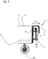
- the rim 6 comprises a groove 8.
- the rim 6 is folded to define such groove 8.
- the groove 8 is configured to receive the profile 7 of the frame 2.
- groove 8 is oversized with respect to the profile 7 of the frame 2, to form the clearance fit.
- the minimum size D1 of the groove 8 is larger than the maximum size D2 of the supporting profile 7.
- the frame 6 of the shelf 3 rests on the profile 7 of the frame 2 without no mechanical constraint relative to the frame 2.
- a user can detach the shelf 3 from the frame 2 by simply lifting it, and does not have to overcome any interference fit.
- a user who wishes to detach the shelf 3 from the frame 2 shall simply apply a force equal the weight of the shelf 3, including the weight of the tableware S possibly located thereon.
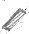
- the bottom 4 of the shelf 3 comprises a grid 9 for supporting the tableware S.
- the shelf 3 also comprises a plurality of teeth 10 arranged on the grid 9 for orderly arrangement of the tableware S.
- the shelf 3 For easier removal/insertion of the upper rack 1 from/into the washing tub, the shelf 3 comprises a handle 12.
- Such handle 12 is preferably formed on a portion of the rim 6, in a zone that can be easily accessed by a user, i.e. a front zone of the rim 6.
- the shelf 3 comprises two or more portions 11 that can be connected to each other so as to define the shelf 3.
- the two or more portions 11 can be coupled to the frame 2 independently of each other.
- the shelf 3 consists of a single portion 11.
Landscapes
- Washing And Drying Of Tableware (AREA)
- Detergent Compositions (AREA)
Abstract
Description
- The present finding relates to a dishwasher with a third basket as defined in the preamble of
claim 1. - Dishwashers having a washing tub which comprises a lower rack, an upper rack and an intermediate rack arranged between the upper rack and the lower rack are known in the art.
- The upper rack, also known as third rack or third basket or third tray, is used for small and/or thin tableware such as cutlery.
- Such upper rack comprises a frame slidably connected to the washing tub, and a shelf designed to receive such tableware, coupled to such frame.
- In certain types of prior art dishwashers the shelf and the frame are permanently constrained relative to each other.
- On the other hand, in other prior art types of dishwashers at least a portion of the shelf is removable with respect to the frame.
- In other types of dishwashers, two or more portions of the shelf, or the whole shelf, can be detached from the frame.
- The removable portion is operable to be carried by a user, e.g. when loading the tableware next to the sink or directly when clearing the table.
- Furthermore, the removable portion allows the intermediate rack to accommodate objects whose extent in a vertical axis is longer than the distance between the bottom of the intermediate drawer and that of the upper drawer. That is, as the shelf is detached from the frame, there will be more room for the objects arranged on the intermediate rack.
- In dishwashers with an at least partially removable shelf, such shelf is designed to be mechanically coupled to the frame, i.e. the shelf is held constrained and cannot move relative to the frame when it is coupled thereto.
- Inconveniently, if a user wishes to remove the shelf, he/she must lift the shelf by applying enough force to overcome the interference fit.
- The application of such force, combined with the lifting movement, often causes jolting of the shelf, eventually leading to the fall of the tableware thereon and possibly to damage thereto.
- Therefore, the technical purpose of the present finding is to provide a dishwasher that can obviate the drawbacks of the prior art.
- In particular, it is an object of the present finding to provide a dishwasher that can offer an alternative solution to the interference fit of the shelf to the frame.
- Also, an object of the present finding is to provide a dishwasher with a removable shelf that affords easier insertion thereof.
- The aforementioned technical purpose and objects are substantially fulfilled by a dishwasher that comprises the technical features as disclosed in one or more of the accompanying claims.
- The present finding can provide a dishwasher that affords easier insertion and/or removal of the upper rack.
- The present finding can also avoid damage and/or fall of the tableware placed on the upper rack.
- Further features and advantages of the present finding will result more clearly from the illustrative, non-limiting description of a practical embodiment of a dishwasher as shown in the accompanying drawings, in which:
-
Figure 1 shows a first perspective view of an upper rack of a dishwasher according to the present finding; -
Figure 2 shows a second perspective view of the rack ofFigure 1 with certain parts omitted; -
Figure 3 shows a side view of a portion of the rack ofFigure 1 ; -
Figure 4 shows a perspective view of a portion of the rack ofFigure 1 . - Referring to the accompanying figures,
numeral 1 designates the upper rack of the dishwasher of the present finding. - The dishwasher of the present finding comprises a washing tub defined by a plurality of walls (not shown) such as a base wall, two side walls, an upper wall and a lower wall.
- The terms upper and lower shall be intended to be related to a proper installation and operation condition of the dishwasher. Here, the term upper designates the portion that is farther from the walkway surface and the term lower designates the portion that is closer to the walkway surface.
- This dishwasher comprises a lower rack (not shown), an
upper rack 1 and an intermediate rack (not shown) arranged between theupper rack 1 and the lower rack. - The racks are placed inside the washing tub, namely the lower rack is placed close to the lower wall of the washing tub and the
upper rack 1 is placed close to the upper wall of the washing tub. - The dishwasher also comprises a lower impeller and an upper impeller (not shown) which send water jets to the tableware for removing dirt.
- The
upper rack 1, or third rack or third drawer or third tray, is designed to accommodate tableware S such as cutlery and kitchen utensils including scissors, spatulas, grippers and other common kitchenware. - It should be noted that the
upper rack 1 comprises aframe 2 slidably connected with the side walls of the washing tub. Theframe 2 compriseswheels 13 to be able to slide. - The
upper rack 1 further comprises ashelf 3, which is designed to receive the aforementioned tableware S, and is adapted to be coupled to theframe 2. - In particular, the
shelf 3 is designed to form a clearance fit with theframe 2. That is, in the dishwasher of the present invention provides theshelf 3 is designed to ensure an interference-free fit with theframe 2. - In particular, the
shelf 3 designed to be fitted on theframe 2 to simply rest thereupon. In other words, according to the present invention, theshelf 3 can move relative to theframe 2, as it is not mechanically constrained relative to theframe 2 when it is coupled thereto. - More in detail, the
shelf 3 extends between abottom 4 and anupper end 5. At theupper end 5, theshelf 3 comprises a perimetrically extendingrim 6. Therim 6 extends along the perimeter with interruptions, as shown in the accompanying figures. Alternatively, therim 6 extends along the perimeter of theshelf 3 in a seamless manner. - The
shelf 3 is configured to rest on theframe 2 at therim 6, thereby forming the clearance fit. - In particular, the
frame 2 comprises a supportingprofile 7. For example, theframe 2 is formed with the typical rod structure of dishwashers. Accordingly, the supportingprofile 7 consists of one of the rods or an assembly thereof. - Therefore, the
shelf 3 contacts theframe 2 only at an upper portion of theprofile 7, i.e. at the point at which theshelf 3 rests on theframe 2. - Particularly referring to
Figure 3 , therim 6 comprises agroove 8. - The
rim 6 is folded to definesuch groove 8. Thegroove 8 is configured to receive theprofile 7 of theframe 2. - It should be noted that the
groove 8 is oversized with respect to theprofile 7 of theframe 2, to form the clearance fit. - In other words, the minimum size D1 of the
groove 8 is larger than the maximum size D2 of the supportingprofile 7. - Advantageously, the
frame 6 of theshelf 3 rests on theprofile 7 of theframe 2 without no mechanical constraint relative to theframe 2. As a result, a user can detach theshelf 3 from theframe 2 by simply lifting it, and does not have to overcome any interference fit. - According to the present invention, a user who wishes to detach the
shelf 3 from theframe 2 shall simply apply a force equal the weight of theshelf 3, including the weight of the tableware S possibly located thereon. - The
bottom 4 of theshelf 3 comprises agrid 9 for supporting the tableware S. Theshelf 3 also comprises a plurality ofteeth 10 arranged on thegrid 9 for orderly arrangement of the tableware S. - For easier removal/insertion of the
upper rack 1 from/into the washing tub, theshelf 3 comprises ahandle 12. Such handle 12 is preferably formed on a portion of therim 6, in a zone that can be easily accessed by a user, i.e. a front zone of therim 6. - The
shelf 3 comprises two ormore portions 11 that can be connected to each other so as to define theshelf 3. Thus, the two ormore portions 11 can be coupled to theframe 2 independently of each other. - Alternatively, the
shelf 3 consists of asingle portion 11.
Claims (9)
- A dishwasher comprising a washing tub defined by two side walls, a lower wall and an upper wall, the dishwasher further comprising a lower rack, an upper rack (1) and an intermediate rack arranged between the upper rack (1) and the lower rack, the upper rack (1) comprising:- a frame (2), slidably connected to the side walls of the washing tub,- a shelf (3), designed to receive tableware (S), the shelf (3) being adapted to be coupled to the frame (2);characterized in that
the shelf (3) is designed to form a clearance fit with the frame (2). - A dishwasher according to claim 1, wherein said shelf (3) extends between a bottom (4) and an upper end (5), the shelf (3) comprising a rim (6) perimetrically extending at the upper end (5), the shelf (3) being configured to rest on the frame (2) at said rim (6) thereby forming said clearance fit.
- A dishwasher as claimed in claim 2, wherein said frame (2) comprises a supporting profile (7), said rim (6) comprising a groove (8) configured to receive said profile (7), the minimum size (D1) of the groove (8) being larger than the maximum size (D2) of the supporting profile (7).
- A dishwasher as claimed in claim 2 or 3, wherein said rim (6) extends perimetrically with or without interruptions.
- A dishwasher as claimed in any of claims 2 to 4, wherein said rim (6) comprises a handle (12).
- A dishwasher as claimed in any of claims 2 to 5, wherein said bottom (4) of said shelf (3) comprises a grid (9) for supporting the tableware (S).
- A dishwasher as claimed in claim 6, wherein the shelf (3) comprises a plurality of teeth (10) arranged on the grid (9) for orderly arrangement of the tableware (S).
- A dishwasher as claimed in any of claims 1 to 7, wherein said shelf (3) comprises two or more portions (11) adapted to be connected to each other to define the shelf (3), the two or more portions (11) being adapted to be independently coupled to the frame (2).
- A dishwasher as claimed in any of claims 1 to 8, wherein said tableware (S) comprises cutlery and kitchen utensils including scissors, spatulas, grippers.
Applications Claiming Priority (1)
| Application Number | Priority Date | Filing Date | Title |
|---|---|---|---|
| IT202020000000388U IT202000000388U1 (en) | 2020-01-29 | 2020-01-29 | Dishwasher with third basket |
Publications (1)
| Publication Number | Publication Date |
|---|---|
| EP3858214A1 true EP3858214A1 (en) | 2021-08-04 |
Family
ID=75438552
Family Applications (1)
| Application Number | Title | Priority Date | Filing Date |
|---|---|---|---|
| EP21153297.3A Withdrawn EP3858214A1 (en) | 2020-01-29 | 2021-01-25 | Dishwasher with a third basket |
Country Status (2)
| Country | Link |
|---|---|
| EP (1) | EP3858214A1 (en) |
| IT (1) | IT202000000388U1 (en) |
Citations (5)
| Publication number | Priority date | Publication date | Assignee | Title |
|---|---|---|---|---|
| US20060219271A1 (en) * | 2005-03-29 | 2006-10-05 | Feddema Mark S | Dishwasher utensil rack and utensil basket therefor |
| EP2554097A2 (en) * | 2011-08-05 | 2013-02-06 | Indesit Company S.p.A. | Dishwasher rack comprising an extractable perimetric frame |
| US20150196189A1 (en) * | 2014-01-10 | 2015-07-16 | General Electric Company | Dishwasher appliance |
| US20150335225A1 (en) * | 2012-12-31 | 2015-11-26 | Indesit Company S.P.A. | A cutlery tray for dishwasher |
| US20190298146A1 (en) * | 2018-03-29 | 2019-10-03 | Bsh Home Appliances Corporation | Modular dishwasher rack with interchangeable and customizable basket inserts |
-
2020
- 2020-01-29 IT IT202020000000388U patent/IT202000000388U1/en unknown
-
2021
- 2021-01-25 EP EP21153297.3A patent/EP3858214A1/en not_active Withdrawn
Patent Citations (5)
| Publication number | Priority date | Publication date | Assignee | Title |
|---|---|---|---|---|
| US20060219271A1 (en) * | 2005-03-29 | 2006-10-05 | Feddema Mark S | Dishwasher utensil rack and utensil basket therefor |
| EP2554097A2 (en) * | 2011-08-05 | 2013-02-06 | Indesit Company S.p.A. | Dishwasher rack comprising an extractable perimetric frame |
| US20150335225A1 (en) * | 2012-12-31 | 2015-11-26 | Indesit Company S.P.A. | A cutlery tray for dishwasher |
| US20150196189A1 (en) * | 2014-01-10 | 2015-07-16 | General Electric Company | Dishwasher appliance |
| US20190298146A1 (en) * | 2018-03-29 | 2019-10-03 | Bsh Home Appliances Corporation | Modular dishwasher rack with interchangeable and customizable basket inserts |
Also Published As
| Publication number | Publication date |
|---|---|
| IT202000000388U1 (en) | 2021-07-29 |
Similar Documents
| Publication | Publication Date | Title |
|---|---|---|
| US20220192462A1 (en) | Fold away cutlery rack | |
| US9033432B2 (en) | Dishwasher | |
| CN102458213B (en) | Dishwasher comprising a cutlery basket | |
| US8714371B2 (en) | Dishwasher basket with a cup support | |
| US20140239784A1 (en) | Dishwasher | |
| US20050268945A1 (en) | Utility shelf for a dishwasher dish rack | |
| EP2326237B1 (en) | A dishwasher with drawer attached to tub roof | |
| US8038805B2 (en) | Multi-piece dishrack for a drawer dishwasher | |
| KR200493288Y1 (en) | Kitchen storage box | |
| US20040099617A1 (en) | Over-the-sink organizer | |
| EP3858214A1 (en) | Dishwasher with a third basket | |
| WO2016192797A1 (en) | Dishwasher comprising a multipurpose stackable tray | |
| JP5927749B2 (en) | System kitchen | |
| CN101573067B (en) | Dishwasher and rack assembly therefor | |
| JP2012120740A (en) | Modular kitchen | |
| WO2016192792A1 (en) | Foldable stemware holder and dishwasher having the same | |
| KR20220061653A (en) | Dish drying rack | |
| KR20180003077U (en) | Shelf multipurpose withdraw for sink | |
| CN105581693B (en) | A kind of multi-functional removable tableware rack and dish-washing machine or disinfection cabinet | |
| EP2368479A1 (en) | Dishwasher with additional basket | |
| EP2322074B1 (en) | Combination of shelves for dishwasher basket | |
| EP3206539A1 (en) | Modular structure for supporting objects, in particular tablewares | |
| EP1776916A1 (en) | Dishes basket for dishwashing machines | |
| EP3200669B1 (en) | Dishwasher comprising a cutlery tray | |
| KR20190103546A (en) | Shelf type Kitchen utensils hanger |
Legal Events
| Date | Code | Title | Description |
|---|---|---|---|
| PUAI | Public reference made under article 153(3) epc to a published international application that has entered the european phase |
Free format text: ORIGINAL CODE: 0009012 |
|
| STAA | Information on the status of an ep patent application or granted ep patent |
Free format text: STATUS: THE APPLICATION HAS BEEN PUBLISHED |
|
| AK | Designated contracting states |
Kind code of ref document: A1 Designated state(s): AL AT BE BG CH CY CZ DE DK EE ES FI FR GB GR HR HU IE IS IT LI LT LU LV MC MK MT NL NO PL PT RO RS SE SI SK SM TR |
|
| STAA | Information on the status of an ep patent application or granted ep patent |
Free format text: STATUS: REQUEST FOR EXAMINATION WAS MADE |
|
| 17P | Request for examination filed |
Effective date: 20220502 |
|
| RBV | Designated contracting states (corrected) |
Designated state(s): AL AT BE BG CH CY CZ DE DK EE ES FI FR GB GR HR HU IE IS IT LI LT LU LV MC MK MT NL NO PL PT RO RS SE SI SK SM TR |
|
| STAA | Information on the status of an ep patent application or granted ep patent |
Free format text: STATUS: EXAMINATION IS IN PROGRESS |
|
| 17Q | First examination report despatched |
Effective date: 20230403 |
|
| STAA | Information on the status of an ep patent application or granted ep patent |
Free format text: STATUS: THE APPLICATION IS DEEMED TO BE WITHDRAWN |
|
| 18D | Application deemed to be withdrawn |
Effective date: 20230815 |