EP3858162B1 - Variable-frequency surface acoustic wave e-cigarette - Google Patents
Variable-frequency surface acoustic wave e-cigarette Download PDFInfo
- Publication number
- EP3858162B1 EP3858162B1 EP20877513.0A EP20877513A EP3858162B1 EP 3858162 B1 EP3858162 B1 EP 3858162B1 EP 20877513 A EP20877513 A EP 20877513A EP 3858162 B1 EP3858162 B1 EP 3858162B1
- Authority
- EP
- European Patent Office
- Prior art keywords
- metal
- average width
- electrode
- acoustic wave
- surface acoustic
- Prior art date
- Legal status (The legal status is an assumption and is not a legal conclusion. Google has not performed a legal analysis and makes no representation as to the accuracy of the status listed.)
- Active
Links
Images


Classifications
-
- A—HUMAN NECESSITIES
- A24—TOBACCO; CIGARS; CIGARETTES; SIMULATED SMOKING DEVICES; SMOKERS' REQUISITES
- A24F—SMOKERS' REQUISITES; MATCH BOXES; SIMULATED SMOKING DEVICES
- A24F40/00—Electrically operated smoking devices; Component parts thereof; Manufacture thereof; Maintenance or testing thereof; Charging means specially adapted therefor
- A24F40/40—Constructional details, e.g. connection of cartridges and battery parts
-
- A—HUMAN NECESSITIES
- A24—TOBACCO; CIGARS; CIGARETTES; SIMULATED SMOKING DEVICES; SMOKERS' REQUISITES
- A24F—SMOKERS' REQUISITES; MATCH BOXES; SIMULATED SMOKING DEVICES
- A24F40/00—Electrically operated smoking devices; Component parts thereof; Manufacture thereof; Maintenance or testing thereof; Charging means specially adapted therefor
- A24F40/05—Devices without heating means
-
- A—HUMAN NECESSITIES
- A24—TOBACCO; CIGARS; CIGARETTES; SIMULATED SMOKING DEVICES; SMOKERS' REQUISITES
- A24F—SMOKERS' REQUISITES; MATCH BOXES; SIMULATED SMOKING DEVICES
- A24F40/00—Electrically operated smoking devices; Component parts thereof; Manufacture thereof; Maintenance or testing thereof; Charging means specially adapted therefor
- A24F40/40—Constructional details, e.g. connection of cartridges and battery parts
- A24F40/44—Wicks
-
- A—HUMAN NECESSITIES
- A24—TOBACCO; CIGARS; CIGARETTES; SIMULATED SMOKING DEVICES; SMOKERS' REQUISITES
- A24F—SMOKERS' REQUISITES; MATCH BOXES; SIMULATED SMOKING DEVICES
- A24F40/00—Electrically operated smoking devices; Component parts thereof; Manufacture thereof; Maintenance or testing thereof; Charging means specially adapted therefor
- A24F40/40—Constructional details, e.g. connection of cartridges and battery parts
- A24F40/46—Shape or structure of electric heating means
-
- A—HUMAN NECESSITIES
- A24—TOBACCO; CIGARS; CIGARETTES; SIMULATED SMOKING DEVICES; SMOKERS' REQUISITES
- A24F—SMOKERS' REQUISITES; MATCH BOXES; SIMULATED SMOKING DEVICES
- A24F40/00—Electrically operated smoking devices; Component parts thereof; Manufacture thereof; Maintenance or testing thereof; Charging means specially adapted therefor
- A24F40/40—Constructional details, e.g. connection of cartridges and battery parts
- A24F40/48—Fluid transfer means, e.g. pumps
-
- A—HUMAN NECESSITIES
- A24—TOBACCO; CIGARS; CIGARETTES; SIMULATED SMOKING DEVICES; SMOKERS' REQUISITES
- A24F—SMOKERS' REQUISITES; MATCH BOXES; SIMULATED SMOKING DEVICES
- A24F40/00—Electrically operated smoking devices; Component parts thereof; Manufacture thereof; Maintenance or testing thereof; Charging means specially adapted therefor
- A24F40/40—Constructional details, e.g. connection of cartridges and battery parts
- A24F40/48—Fluid transfer means, e.g. pumps
- A24F40/485—Valves; Apertures
-
- A—HUMAN NECESSITIES
- A24—TOBACCO; CIGARS; CIGARETTES; SIMULATED SMOKING DEVICES; SMOKERS' REQUISITES
- A24F—SMOKERS' REQUISITES; MATCH BOXES; SIMULATED SMOKING DEVICES
- A24F40/00—Electrically operated smoking devices; Component parts thereof; Manufacture thereof; Maintenance or testing thereof; Charging means specially adapted therefor
- A24F40/60—Devices with integrated user interfaces
-
- A—HUMAN NECESSITIES
- A24—TOBACCO; CIGARS; CIGARETTES; SIMULATED SMOKING DEVICES; SMOKERS' REQUISITES
- A24F—SMOKERS' REQUISITES; MATCH BOXES; SIMULATED SMOKING DEVICES
- A24F40/00—Electrically operated smoking devices; Component parts thereof; Manufacture thereof; Maintenance or testing thereof; Charging means specially adapted therefor
- A24F40/90—Arrangements or methods specially adapted for charging batteries thereof
-
- A—HUMAN NECESSITIES
- A24—TOBACCO; CIGARS; CIGARETTES; SIMULATED SMOKING DEVICES; SMOKERS' REQUISITES
- A24F—SMOKERS' REQUISITES; MATCH BOXES; SIMULATED SMOKING DEVICES
- A24F40/00—Electrically operated smoking devices; Component parts thereof; Manufacture thereof; Maintenance or testing thereof; Charging means specially adapted therefor
- A24F40/90—Arrangements or methods specially adapted for charging batteries thereof
- A24F40/95—Arrangements or methods specially adapted for charging batteries thereof structurally associated with cases
-
- B—PERFORMING OPERATIONS; TRANSPORTING
- B05—SPRAYING OR ATOMISING IN GENERAL; APPLYING FLUENT MATERIALS TO SURFACES, IN GENERAL
- B05B—SPRAYING APPARATUS; ATOMISING APPARATUS; NOZZLES
- B05B17/00—Apparatus for spraying or atomising liquids or other fluent materials, not covered by the preceding groups
- B05B17/04—Apparatus for spraying or atomising liquids or other fluent materials, not covered by the preceding groups operating with special methods
- B05B17/06—Apparatus for spraying or atomising liquids or other fluent materials, not covered by the preceding groups operating with special methods using ultrasonic or other kinds of vibrations
- B05B17/0607—Apparatus for spraying or atomising liquids or other fluent materials, not covered by the preceding groups operating with special methods using ultrasonic or other kinds of vibrations generated by electrical means, e.g. piezoelectric transducers
-
- B—PERFORMING OPERATIONS; TRANSPORTING
- B06—GENERATING OR TRANSMITTING MECHANICAL VIBRATIONS IN GENERAL
- B06B—METHODS OR APPARATUS FOR GENERATING OR TRANSMITTING MECHANICAL VIBRATIONS OF INFRASONIC, SONIC, OR ULTRASONIC FREQUENCY, e.g. FOR PERFORMING MECHANICAL WORK IN GENERAL
- B06B1/00—Methods or apparatus for generating mechanical vibrations of infrasonic, sonic, or ultrasonic frequency
- B06B1/02—Methods or apparatus for generating mechanical vibrations of infrasonic, sonic, or ultrasonic frequency making use of electrical energy
- B06B1/0207—Driving circuits
- B06B1/0223—Driving circuits for generating signals continuous in time
- B06B1/0269—Driving circuits for generating signals continuous in time for generating multiple frequencies
- B06B1/0284—Driving circuits for generating signals continuous in time for generating multiple frequencies with consecutive, i.e. sequential generation, e.g. with frequency sweep
-
- B—PERFORMING OPERATIONS; TRANSPORTING
- B06—GENERATING OR TRANSMITTING MECHANICAL VIBRATIONS IN GENERAL
- B06B—METHODS OR APPARATUS FOR GENERATING OR TRANSMITTING MECHANICAL VIBRATIONS OF INFRASONIC, SONIC, OR ULTRASONIC FREQUENCY, e.g. FOR PERFORMING MECHANICAL WORK IN GENERAL
- B06B3/00—Methods or apparatus specially adapted for transmitting mechanical vibrations of infrasonic, sonic, or ultrasonic frequency
-
- H—ELECTRICITY
- H03—ELECTRONIC CIRCUITRY
- H03H—IMPEDANCE NETWORKS, e.g. RESONANT CIRCUITS; RESONATORS
- H03H9/00—Networks comprising electromechanical or electro-acoustic elements; Electromechanical resonators
- H03H9/02—Details
- H03H9/125—Driving means, e.g. electrodes, coils
- H03H9/145—Driving means, e.g. electrodes, coils for networks using surface acoustic waves
- H03H9/14538—Formation
- H03H9/14541—Multilayer finger or busbar electrode
-
- H—ELECTRICITY
- H03—ELECTRONIC CIRCUITRY
- H03H—IMPEDANCE NETWORKS, e.g. RESONANT CIRCUITS; RESONATORS
- H03H9/00—Networks comprising electromechanical or electro-acoustic elements; Electromechanical resonators
- H03H9/15—Constructional features of resonators consisting of piezoelectric or electrostrictive material
- H03H9/17—Constructional features of resonators consisting of piezoelectric or electrostrictive material having a single resonator
- H03H9/176—Constructional features of resonators consisting of piezoelectric or electrostrictive material having a single resonator consisting of ceramic material
-
- H—ELECTRICITY
- H03—ELECTRONIC CIRCUITRY
- H03H—IMPEDANCE NETWORKS, e.g. RESONANT CIRCUITS; RESONATORS
- H03H9/00—Networks comprising electromechanical or electro-acoustic elements; Electromechanical resonators
- H03H9/25—Constructional features of resonators using surface acoustic waves
-
- H—ELECTRICITY
- H05—ELECTRIC TECHNIQUES NOT OTHERWISE PROVIDED FOR
- H05K—PRINTED CIRCUITS; CASINGS OR CONSTRUCTIONAL DETAILS OF ELECTRIC APPARATUS; MANUFACTURE OF ASSEMBLAGES OF ELECTRICAL COMPONENTS
- H05K1/00—Printed circuits
- H05K1/02—Details
- H05K1/11—Printed elements for providing electric connections to or between printed circuits
- H05K1/111—Pads for surface mounting, e.g. lay-out
-
- A—HUMAN NECESSITIES
- A24—TOBACCO; CIGARS; CIGARETTES; SIMULATED SMOKING DEVICES; SMOKERS' REQUISITES
- A24F—SMOKERS' REQUISITES; MATCH BOXES; SIMULATED SMOKING DEVICES
- A24F40/00—Electrically operated smoking devices; Component parts thereof; Manufacture thereof; Maintenance or testing thereof; Charging means specially adapted therefor
- A24F40/10—Devices using liquid inhalable precursors
-
- B—PERFORMING OPERATIONS; TRANSPORTING
- B05—SPRAYING OR ATOMISING IN GENERAL; APPLYING FLUENT MATERIALS TO SURFACES, IN GENERAL
- B05B—SPRAYING APPARATUS; ATOMISING APPARATUS; NOZZLES
- B05B17/00—Apparatus for spraying or atomising liquids or other fluent materials, not covered by the preceding groups
- B05B17/04—Apparatus for spraying or atomising liquids or other fluent materials, not covered by the preceding groups operating with special methods
- B05B17/06—Apparatus for spraying or atomising liquids or other fluent materials, not covered by the preceding groups operating with special methods using ultrasonic or other kinds of vibrations
- B05B17/0607—Apparatus for spraying or atomising liquids or other fluent materials, not covered by the preceding groups operating with special methods using ultrasonic or other kinds of vibrations generated by electrical means, e.g. piezoelectric transducers
- B05B17/0653—Details
- B05B17/0669—Excitation frequencies
-
- B—PERFORMING OPERATIONS; TRANSPORTING
- B06—GENERATING OR TRANSMITTING MECHANICAL VIBRATIONS IN GENERAL
- B06B—METHODS OR APPARATUS FOR GENERATING OR TRANSMITTING MECHANICAL VIBRATIONS OF INFRASONIC, SONIC, OR ULTRASONIC FREQUENCY, e.g. FOR PERFORMING MECHANICAL WORK IN GENERAL
- B06B2201/00—Indexing scheme associated with B06B1/0207 for details covered by B06B1/0207 but not provided for in any of its subgroups
- B06B2201/50—Application to a particular transducer type
- B06B2201/55—Piezoelectric transducer
-
- B—PERFORMING OPERATIONS; TRANSPORTING
- B06—GENERATING OR TRANSMITTING MECHANICAL VIBRATIONS IN GENERAL
- B06B—METHODS OR APPARATUS FOR GENERATING OR TRANSMITTING MECHANICAL VIBRATIONS OF INFRASONIC, SONIC, OR ULTRASONIC FREQUENCY, e.g. FOR PERFORMING MECHANICAL WORK IN GENERAL
- B06B2201/00—Indexing scheme associated with B06B1/0207 for details covered by B06B1/0207 but not provided for in any of its subgroups
- B06B2201/70—Specific application
- B06B2201/77—Atomizers
Definitions
- the present invention belongs to the technical field of electronic cigarettes, and more particularly, relates to a variable-frequency surface acoustic wave electronic cigarette.
- electrically-heated atomizing electronic cigarettes occupy the mainstream market of electronic cigarettes. They use resistance wires for heating to generate localized high temperatures so that the e-liquid in the cotton core or porous ceramic sheet is atomized to form an aerosol for users to smoke.
- the electrically-heated atomizing electronic cigarette has a substantial rate of heat conduction and atomization efficiency. Under the action of high temperature, however, harmful substances such as formaldehyde, carbon monoxide and others are easily produced, which not only causes health and safety risks, but also greatly reduces the experience of smoking.
- Another type of electronic cigarette is an ultrasonic atomizing electronic cigarette.
- the ultrasonic atomizing electronic cigarette requires a thin layer of e-liquid to be evenly spread on an entire surface of an atomizing sheet to realize atomization. If the e-liquid accumulates, the amount of smoke created will vary, sometimes large and sometimes small during use of the electronic cigarette, and even the smoke with a large particle size will be produced. When such smoke is inhaled into the mouth along an airflow channel by the user, it will reduce the user experience. In addition, the amount of smoke through the pure ultrasonic atomization is smaller than that of the electrically-heated atomization, and an auxiliary ceramic heating sheet is required to increase the amount of smoke to satisfy the user's experience demand for hot smoke.
- the applicant designed an electronic cigarette system, which uses a surface acoustic wave to achieve atomization of e-liquid (refer to the Chinese Patent ZL201810076941.1 ).
- the electronic cigarette system effectively prevents the potential safety and health risks caused by rapid high heat of the electrically-heated atomization, and solves the problems of high consumption, lower efficiency and poor experience of the ultrasonic atomization.
- the smoke particle size is basically determined and cannot be adjusted arbitrarily, thereby affecting the smoking experience.
- CA3013531 concerns a known electronic cigarette using a surface acoustic wave transducer.
- the present invention provides a variable-frequency surface acoustic wave electronic cigarette, which realizes atomization of e-liquid using the diffraction energy of the surface acoustic wave, and enables a range of a surface acoustic wave frequency to be adjustable through a structural design of a special atomization chip to further realize the effective adjustment of a smoke particle size after the atomization of the e-liquid.
- the electronic cigarette of the present invention has a simple overall structure, convenient assembly, and high atomization efficiency, and can effectively satisfy users' different smoking experiences.
- the present invention provides a variable-frequency surface acoustic wave electronic cigarette, which includes an atomizer 2.
- An atomization cavity 213 is disposed in the atomizer 2, and a variable-frequency surface acoustic wave atomization chip 203 is disposed at a lower portion of the atomization cavity 213.
- An inverted trapezoidal interdigital transducer 2037 is disposed on the variable-frequency surface acoustic wave atomization chip 203.
- An e-liquid storage cavity 205 is disposed in the atomization cavity 213.
- a porous ceramic sheet 204 is disposed between the e-liquid storage cavity 205 and the atomization chip 203.
- the inverted trapezoidal interdigital transducer 2037 includes a plurality of metal interdigital electrodes a , b and reflective electrodes c, which are in an inverted trapezoidal shape.
- the inverted trapezoidal interdigital transducer 2037 further includes two metal electrode bus bars, namely a first metal electrode bus bar 20361 and a second metal electrode bus bar 20362.
- a plurality of first metal interdigital electrodes a are connected to the first metal electrode bus bar 20361 through a relatively long trapezoidal bottom
- a plurality of second metal interdigital electrodes b are connected to the second metal electrode bus bar 20362 through a relatively short trapezoidal bottom.
- the plurality of first metal interdigital electrodes a and the plurality of second metal interdigital electrodes b are arranged in a finger-crossed shape, and a reflective electrode c is embedded between a first metal interdigital electrode a and a second metal interdigital electrode b.
- an arrangement manner of the metal interdigital electrodes and reflective electrodes is: the first metal interdigital electrode a , a first gap d 1 , the second metal interdigital electrode b, a second gap d 2 , the reflective electrode c, a third gap d 3 , the first metal interdigital electrode a , ....
- the above arrangement continues in a plurality of groups to constitute the inverted trapezoidal interdigital transducer 2037.
- An average width of the first gap d 1 is identical to an average width of the first metal interdigital electrode a.
- An average width of the second gap d 2 is identical to an average width of the second metal interdigital electrode b.
- An average width of the third gap d 3 is identical to an average width of the reflective electrode c.
- a shape of the first metal interdigital electrode a and a shape of the second metal interdigital electrode b are identical.
- the sum of the average width of the first metal interdigital electrode a , the average width of the first gap d 1 , the average width of the second metal interdigital electrode b, the average width of the second gap d 2 , the average width of the reflective electrode c and the average width of the third gap d 3 is a wavelength p of the surface acoustic wave.
- the average width of the first metal interdigital electrode a is one eighth of the wavelength of the surface acoustic wave
- the average width of the third gap d 3 or the average width of the reflective electrode c is a quarter of the wavelength of the surface acoustic wave.
- the atomization chip 203 further successively includes: a heat sink layer 2031, a heat conduction layer 2032 and a piezoelectric substrate layer 2033.
- the inverted trapezoidal interdigital transducer 2037 is disposed on the piezoelectric substrate layer 2033.
- Two separate printed circuit board PCB bonding pads namely a first PCB bonding pad 20341 and a second PCB bonding pad 20342, are further disposed on the piezoelectric substrate layer 2033.
- the first metal electrode bus bar 20361 is connected to the first PCB bonding pad 20341 through a power connection wire 2035
- the second metal electrode bus bar 20362 is connected to the second PCB bonding pad 20342 through a power connection wire 2035.
- the electronic cigarette further includes an electric core 3.
- a circuit board 307 and a battery 305 are disposed in the electric core 3, and the electric core 3 is conductively connected to the first PCB bonding pad 20341 and the second PCB bonding pad 20342 through a magnetic thimble 212.
- the atomizer 2 is provided with an atomizer housing 209.
- An airflow channel 208 is disposed inside the atomizer housing 209, and a suction nozzle 1 is disposed outside the atomizer housing 209.
- the suction nozzle 1 is in communication with and connected to the airflow channel 208.
- An airflow inlet 210 is formed on the atomizer housing 209, and the airflow inlet 210 and the inverted trapezoidal interdigital transducer 2037 are on an identical horizontal plane.
- the electronic cigarette further includes a protective shell 301.
- the electric core 3 is disposed in the protective shell 301.
- a button 5, an indicator light 6 and a charging port 302 are disposed outside the protective shell 301.
- the present invention has the following advantages.
- e-liquid injection round hole 2031. heat sink; 2032. heat conduction layer; 2033. piezoelectric substrate layer; 20341. first PCB bonding pad; 20342. second PCB bonding pad; 2035. power connection wire; 20361. first metal electrode bus bar; 20362. second metal electrode bus bar; 2037. inverted trapezoidal interdigital transducer; a. first metal interdigital electrode; b. second metal interdigital electrode; c. reflective electrode; d 1 . first gap; d 2 . second gap; d 3 . third gap; p. wavelength of surface acoustic wave; and W. internal range of inverted trapezoidal interdigital transducer.
- FIG. 1 shows a schematic diagram of the structure of a variable-frequency surface acoustic wave electronic cigarette of the present invention, which includes the suction nozzle 1, the atomizer 2, the electric core 3, the e-liquid injection hole 4, the button 5 and the indicator light 6.
- the atomizer 2 and the electric core 3 are firmly contiguously connected through the magnetic thimble 212.
- the suction nozzle 1 is configured for the user to smoke the smoke.
- the atomizer 2 is configured to atomize the e-liquid to produce the smoke.
- the electric core 3 is configured to provide a drive signal source to the atomizer 2.
- the e-liquid injection hole 4 is configured to fill the e-liquid.
- the button 5 is configured to realize operations of turning the electronic cigarette on and off, adjusting a frequency of the drive signal source and controlling an output of the signal source, and other operations.
- the indicator light 6 is configured to display the working status and electric quantity of the electronic cigarette.
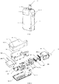
- FIG. 2 shows an exploded view of the variable-frequency surface acoustic wave electronic cigarette of the present invention.
- the suction nozzle 1 is located on the top of the atomizer 2.
- An internal structure of the atomizer includes the bottom board 201, the silicone gasket 202, the variable-frequency surface acoustic wave atomization chip 203, the porous ceramic sheet 204, the e-liquid storage cavity 205, the silicone sealing sheet 206, the first screw 207, the airflow channel 208, the atomizer housing 209, the airflow inlet 210, the atomization chip stopper 211, the magnetic thimble 212 and the atomization cavity 213.
- the electric core 3 is provided with the protective shell 301, the charging port 302, the stop body 303, the screw cap 304, the battery 305, the second screw 306, the circuit board 307 and the bottom cover 308.
- the e-liquid injection hole 4 is located on the top of the atomizer 2 and located on a side of the suction nozzle 1, and includes the silicone e-liquid injection hole plug 401 and the e-liquid injection round hole 402 located on the top of the atomizer.
- the button 5 is located on a side of the protective shell 301 of the electric core 3.
- the indicator light 6 is located on the lower right side of the protective shell 301 of the electric core 3.
- the atomization chip 203 successively includes the heat sink 2031, the heat conduction layer 2032, the piezoelectric substrate layer 2033, the first printed circuit board (PCB) bonding pad 20341, the second PCB bonding pad 20342, the power connection wire 2035, the first metal electrode bus bar 20361, the second metal electrode bus bar 20362, and the inverted trapezoidal interdigital transducer 2037.
- the atomizer housing 209 of the atomizer 2 and the protective shell 301 and the bottom cover 308 of the electric core 3 are all made of aluminum alloy materials having good heat conduction and heat dissipation effects.
- the porous ceramic sheet 204 is made of silicate materials having good porosity (the porosity is generally in the range of 40%-70%), high temperature and high pressure resistance and acid and alkali corrosion resistance.
- the heat sink 2031 is made of aluminum sheet having an excellent heat dissipation effect and a low cost, and the bottom of the heat sink 2031 is provided with grooves.
- the heat conduction layer 2032 is made of heat conduction silicone grease sheets having good bonding performance and heat conduction capability.
- the piezoelectric substrate layer 2033 selects a 128 ° lithium niobate single crystal chip propagating in a direction of Y being tangent to X, with a thickness of 1 mm-2 mm, an electromechanical coupling coefficient of 5.5%, a propagation velocity of the surface acoustic wave of about 3990 m/s, and a temperature coefficient of -72 ⁇ 10-6/°C.
- the power connection wire 2035 employs a gold wire or a silver wire, which has a diameter of reaching 100 ⁇ m and can be used for a binding process.
- the first metal electrode bus bar 20361, the second metal electrode bus bar 20362 and the metal interdigital electrodes a and b are made of aluminum, silver, gold or other materials having good electrical conductivity.
- the structure of the metal interdigital electrodes a and b employs an apodization structure having crossed metal strips with a wide top and a narrow bottom, namely an inverted trapezoidal structure.
- FIG. 3 and FIG. 4 show a cross-sectional view and an exploded view of the atomizer of the variable-frequency surface acoustic wave electronic cigarette of the present invention, respectively.
- the atomization chip 203 is placed in the atomization chip stopper 211, and the atomization cavity 213 is provided at the upper end of the atomization chip stopper 211.
- the e-liquid storage cavity 205 is provided at the lower end of the silicone sealing sheet 206.
- the porous ceramic sheet 204 employs a bowl-shaped structure with a convex portion around a middle recessed portion, and a size thereof are exactly matched with the lower port of the e-liquid storage cavity 205 to form a whole e-liquid storing and guiding structure.
- the assembled silicone sealing sheet 206 and porous ceramic sheet 204 are placed on the upper end of the atomization chip stopper 211.
- the e-liquid storage cavity 205 and the porous ceramic sheet 204 are exactly located in the atomization cavity 213.
- the porous ceramic sheet 204 is fitted with the upper surface of the atomization chip 203 to realize the supply and transmission of e-liquid.
- the magnetic thimble 212 is mounted at the right end of the atomization chip stopper 211, and is configured to access the drive signal source.
- the above assembly structure is placed in the atomizer housing 209, and a piece of silicone gasket 202 is pasted on the bottom of the above assembly structure to realize heat insulation and sealing.
- the bottom board 201 is covered, and the first screw 207 is screwed to fix the entire atomizer.
- the e-liquid is injected from the e-liquid injection round hole 402 on the top of the atomizer 2, and the entire e-liquid storage cavity 205 will be automatically fully filled after the e-liquid is injected.
- the silicone e-liquid injection hole plug 401 is inserted into the e-liquid injection round hole 402 for sealing.
- the air carries the e-liquid atomized smoke from the end surface of the porous ceramic sheet 204 disposed on the surface of the atomization chip 203 in the atomizer 2 to enter the suction nozzle 1 through the airflow channel 208 for the smoker to smoke.
- the electric core 3 of the above electronic cigarette further includes: the protective shell 301, the charging port 302, the stop body 303, the screw cap 304, the battery 305, the second screw 306, the circuit board 307 and the bottom cover 308.
- the circuit board 307 is placed in the stop body 303, and the battery 305 is placed at the lower part of the circuit board 307 to ensure that the charging port 302 of the circuit board 307 is aligned with the stop body 303.
- the button 5 is installed on a side of the protective shell 301 of the electric core 3, then the above assembly is placed in the protective shell 301, and the charging port is also ensured to be aligned with the charging port 302 of the bottom of the protective shell 301.
- the button 5 is connected to a button output port of the circuit board 307 through a wire.
- the magnetic thimble 212 is provided at the top of the protective shell 301, is connected to a signal output end of the circuit board 307 through the wire, and is fixed using the second screw 306 and the screw cap 304.
- the indicator light 6 is exactly located on the lower right side of the protective shell 301 of the electric core 3.
- the bottom cover 308 is fastened to complete the assembling and connection of the electric core.
- FIG. 5 shows a schematic diagram of the structure of the atomization chip of the variable-frequency surface acoustic wave electronic cigarette of the present invention.
- the atomization chip successively includes: the heat sink 2031, the heat conduction layer 2032, the piezoelectric substrate layer 2033, the first PCB bonding pad 20341, the second PCB bonding pad 20342, the power connection wire 2035, and the inverted trapezoidal interdigital transducer 2037.
- the inverted trapezoidal interdigital transducer 2037 includes two metal electrode bus bars, namely the first metal electrode bus bar 20361 and the second metal electrode bus bar 20362.
- a plurality of first metal interdigital electrodes a are connected to the first metal electrode bus bar 20361 through a relatively long trapezoidal bottom, and a plurality of second metal interdigital electrodes b are connected to the second metal electrode bus bar 20362 through a relatively short trapezoidal bottom.
- the plurality of the first metal interdigital electrodes a and the plurality of the second metal interdigital electrodes b are arranged in a finger-crossed shape.
- the reflective electrode c is embedded between the first metal interdigital electrode a and the second metal interdigital electrode b, and the reflective electrode c is not connected to any metal electrode bus bar.
- Each of the inverted trapezoidal interdigital transducer 2037, the first PCB bonding pad 20341, the second PCB bonding pad 20342 and the piezoelectric substrate layer 2033 is adhered to the upper surface of the heat sink 2031 through the heat conduction layer 2032.
- the first PCB bonding pad 20341 and the second PCB bonding pad 20342 are connected to the first metal electrode bus bar 20361 and the second metal electrode bus bar 20362 using the power connection wire 2035 through the binding process, respectively.
- the other end of the first PCB bonding pad 20341 and the other end of the second PCB bonding pad 20342 are assembled and connected through the magnetic thimble 212 disposed between the atomizer 2 and the electric core 3 to realize the input of the signal source.
- FIG. 5 shows the partial enlarged view of the shape of the inverted trapezoidal interdigital transducer 2037.
- a frequency of the surface acoustic wave generated by the atomization chip 203 is determined by the structure of the inverted trapezoidal interdigital transducer 2037.
- the arrangement manner of the metal interdigital electrodes and the reflective electrodes is: the first metal interdigital electrode a , the first gap d 1 , the second metal interdigital electrode b, the second gap d 2 , the reflective electrode c, the third gap d 3 , the first metal interdigital electrode a , ..., and the above arrangement continues in a plurality of groups to constitute the inverted trapezoidal interdigital transducer 2037.
- the average width of the first gap d 1 is identical to the average width of the first metal interdigital electrode a.
- the average width of the second gap d 2 is identical to the average width of the second metal interdigital electrode b.
- the average width of the third gap d 3 is identical to the average width of the reflective electrode c.
- the frequency range of the generated surface acoustic wave is 20 MHz - 100 MHz, it is required that, within the W range of the inverted trapezoidal interdigital transducer 2037 (refer to the partial enlarged view at the upper part of FIG.
- each of the uppermost end of the first metal interdigital electrode a , the uppermost end of the first gap d 1 , the uppermost end of the second metal interdigital electrode b, and the uppermost end of the second gap d 2 takes a value of 15 ⁇ m
- each of the lowermost end of the first metal interdigital electrode a , the lowermost end of the first gap d 1 , the lowermost end of the second metal interdigital electrode b, and the lowermost end of the second gap d 2 takes a value of 5 ⁇ m, that is, the change range of the wavelength is 200 ⁇ m - 40 ⁇ m.
- a method for using the variable-frequency surface acoustic wave electronic cigarette of the present invention includes the following steps.
- the electric core 3 is externally connected to a charging wire through the charging port 302 to complete the charging of the battery.
- the e-liquid is injected through the e-liquid injection hole 4, and the e-liquid fills the e-liquid storage cavity 205, then permeates into the porous ceramic sheet 204 and finally reaches the surface of the atomization chip 203 and is locked.
- the atomizer 2 is connected to the electric core 3 through the magnetic thimble 212. After the button 5 is turned on, the signal source and the atomization chip 203 realize the signal input and communication.
- the input electric signal is converted into a mechanical vibration signal to generate a surface acoustic wave propagating along the surface of the piezoelectric substrate layer 2033.
- the surface acoustic wave is transmitted to a contact area of the porous ceramic sheet 204, the surface acoustic wave sucks out the e-liquid locked by the porous ceramic sheet 204, and a liquid film is formed between the surface of the piezoelectric substrate layer 2033 and the end surface of the porous ceramic sheet 204.
- the energy of the surface acoustic wave is diffracted into the liquid film of the e-liquid to produce an acoustic streaming effect and form an acoustic streaming force.
- the acoustic streaming force overcomes the surface tension and viscosity force of the liquid film of the e-liquid to enable the e-liquid to produce the smoke with a nano-sized particle size.
- Suction is performed through the suction nozzle 1, and the peripheral air flows in from the airflow inlet 210, flows through the e-liquid atomization area, and transmits the atomized smoke into the mouth of the user along the airflow channel 208 and the suction nozzle 1.
- the electric core 3 automatically stops the output to prevent excessive suction.
- the signal can be output normally by long pressing the button 5 again, so that the connected atomization chip 203 works normally and completes the atomization of the e-liquid.
- the button 5 is pressed twice within 0.5 s to enter a frequency cycle adjustment mode. Each time the button 5 is pressed twice, the frequency is stepped by 10 MHz, there is a cycle of nine grades between 20 MHz - 100 MHz, and the particle size of the particle obtained after atomization of the e-liquid can be adjusted arbitrarily. Of course, the frequency range and the grades can also be selected as other settings.
- the electronic cigarette starts the running according to the set data retained when it is powered off at the last time.
- the electric core 3 enters a standby power saving mode. After the button 5 is continuously pressed five times within 2 s in the power-on state, the electric core 3 is powered off, and the indicator light 6 flashes red for prompt. In the whole process, the indicator light 6 displays different colors according to the electric quantity of the battery from high to low, such as green (electric quantity > 70%), blue (electric quantity between 70% and 30%), and red (electric quantity ⁇ 30%). If the electric quantity of the battery is lower than 10% during use, the indicator light will flash and the electronic cigarette will automatically power off.
- the atomization chip can also work in a continuous frequency range, such as 20 MHz - 100 MHz, and each frequency point corresponds to one smoke particle size after atomization of the e-liquid. According to the taste of the user, the smoke particle sizes can be set arbitrarily to obtain different smoke particle sizes.
Landscapes
- Engineering & Computer Science (AREA)
- Physics & Mathematics (AREA)
- Acoustics & Sound (AREA)
- Mechanical Engineering (AREA)
- Chemical & Material Sciences (AREA)
- Ceramic Engineering (AREA)
- Microelectronics & Electronic Packaging (AREA)
- Human Computer Interaction (AREA)
- Special Spraying Apparatus (AREA)
Description
- The present invention belongs to the technical field of electronic cigarettes, and more particularly, relates to a variable-frequency surface acoustic wave electronic cigarette.
- At present, electrically-heated atomizing electronic cigarettes occupy the mainstream market of electronic cigarettes. They use resistance wires for heating to generate localized high temperatures so that the e-liquid in the cotton core or porous ceramic sheet is atomized to form an aerosol for users to smoke. The electrically-heated atomizing electronic cigarette has a substantial rate of heat conduction and atomization efficiency. Under the action of high temperature, however, harmful substances such as formaldehyde, carbon monoxide and others are easily produced, which not only causes health and safety risks, but also greatly reduces the experience of smoking. Another type of electronic cigarette is an ultrasonic atomizing electronic cigarette. The ultrasonic atomizing electronic cigarette requires a thin layer of e-liquid to be evenly spread on an entire surface of an atomizing sheet to realize atomization. If the e-liquid accumulates, the amount of smoke created will vary, sometimes large and sometimes small during use of the electronic cigarette, and even the smoke with a large particle size will be produced. When such smoke is inhaled into the mouth along an airflow channel by the user, it will reduce the user experience. In addition, the amount of smoke through the pure ultrasonic atomization is smaller than that of the electrically-heated atomization, and an auxiliary ceramic heating sheet is required to increase the amount of smoke to satisfy the user's experience demand for hot smoke.
- In order to solve the aforementioned problems, the applicant designed an electronic cigarette system, which uses a surface acoustic wave to achieve atomization of e-liquid (refer to the
Chinese Patent ZL201810076941.1 -
CA3013531 concerns a known electronic cigarette using a surface acoustic wave transducer. - In order to solve the above problems, the present invention is proposed.
- The present invention provides a variable-frequency surface acoustic wave electronic cigarette, which realizes atomization of e-liquid using the diffraction energy of the surface acoustic wave, and enables a range of a surface acoustic wave frequency to be adjustable through a structural design of a special atomization chip to further realize the effective adjustment of a smoke particle size after the atomization of the e-liquid. The electronic cigarette of the present invention has a simple overall structure, convenient assembly, and high atomization efficiency, and can effectively satisfy users' different smoking experiences.
- The present invention provides a variable-frequency surface acoustic wave electronic cigarette, which includes an
atomizer 2. Anatomization cavity 213 is disposed in theatomizer 2, and a variable-frequency surface acousticwave atomization chip 203 is disposed at a lower portion of theatomization cavity 213. An inverted trapezoidalinterdigital transducer 2037 is disposed on the variable-frequency surface acousticwave atomization chip 203. Ane-liquid storage cavity 205 is disposed in theatomization cavity 213. A porousceramic sheet 204 is disposed between thee-liquid storage cavity 205 and theatomization chip 203. - According to the invention, the inverted trapezoidal
interdigital transducer 2037 includes a plurality of metal interdigital electrodes a, b and reflective electrodes c, which are in an inverted trapezoidal shape. The inverted trapezoidalinterdigital transducer 2037 further includes two metal electrode bus bars, namely a first metalelectrode bus bar 20361 and a second metalelectrode bus bar 20362. A plurality of first metal interdigital electrodes a are connected to the first metalelectrode bus bar 20361 through a relatively long trapezoidal bottom, and a plurality of second metal interdigital electrodes b are connected to the second metalelectrode bus bar 20362 through a relatively short trapezoidal bottom. The plurality of first metal interdigital electrodes a and the plurality of second metal interdigital electrodes b are arranged in a finger-crossed shape, and a reflective electrode c is embedded between a first metal interdigital electrode a and a second metal interdigital electrode b. - Preferably, an arrangement manner of the metal interdigital electrodes and reflective electrodes is: the first metal interdigital electrode a, a first gap d1, the second metal interdigital electrode b, a second gap d2 , the reflective electrode c, a third gap d3 , the first metal interdigital electrode a, .... The above arrangement continues in a plurality of groups to constitute the inverted trapezoidal
interdigital transducer 2037. An average width of the first gap d1 is identical to an average width of the first metal interdigital electrode a. An average width of the second gap d2 is identical to an average width of the second metal interdigital electrode b. An average width of the third gap d3 is identical to an average width of the reflective electrode c. - Preferably, a shape of the first metal interdigital electrode a and a shape of the second metal interdigital electrode b are identical. The sum of the average width of the first metal interdigital electrode a, the average width of the first gap d1 , the average width of the second metal interdigital electrode b, the average width of the second gap d2 , the average width of the reflective electrode c and the average width of the third gap d3 is a wavelength p of the surface acoustic wave. It is satisfied that the average width of the first metal interdigital electrode a, or the average width of the first gap d1 , or the average width of the second metal interdigital electrode b or the average width of the second gap d2 is one eighth of the wavelength of the surface acoustic wave, and the average width of the third gap d3 or the average width of the reflective electrode c is a quarter of the wavelength of the surface acoustic wave.
- Preferably, the
atomization chip 203 further successively includes: aheat sink layer 2031, aheat conduction layer 2032 and apiezoelectric substrate layer 2033. The inverted trapezoidalinterdigital transducer 2037 is disposed on thepiezoelectric substrate layer 2033. Two separate printed circuit board PCB bonding pads, namely a firstPCB bonding pad 20341 and a secondPCB bonding pad 20342, are further disposed on thepiezoelectric substrate layer 2033. The first metalelectrode bus bar 20361 is connected to the firstPCB bonding pad 20341 through apower connection wire 2035, and the second metalelectrode bus bar 20362 is connected to the secondPCB bonding pad 20342 through apower connection wire 2035. - Preferably, the electronic cigarette further includes an
electric core 3. Acircuit board 307 and abattery 305 are disposed in theelectric core 3, and theelectric core 3 is conductively connected to the firstPCB bonding pad 20341 and the secondPCB bonding pad 20342 through amagnetic thimble 212. - Preferably, the
atomizer 2 is provided with anatomizer housing 209. Anairflow channel 208 is disposed inside theatomizer housing 209, and asuction nozzle 1 is disposed outside theatomizer housing 209. Thesuction nozzle 1 is in communication with and connected to theairflow channel 208. Anairflow inlet 210 is formed on theatomizer housing 209, and theairflow inlet 210 and the inverted trapezoidalinterdigital transducer 2037 are on an identical horizontal plane. - Preferably, the electronic cigarette further includes a
protective shell 301. Theelectric core 3 is disposed in theprotective shell 301. Abutton 5, anindicator light 6 and acharging port 302 are disposed outside theprotective shell 301. - The present invention has the following advantages.
- 1. The surface acoustic wave is a kind of mechanical wave, of which energy is concentrated on the surface. The energy loss in a propagation direction is small (even negligible without interference from other medias). The energy is exponentially attenuated in a direction perpendicular to the propagation direction of the wave. The range of the vibration frequency of the surface acoustic wave is as high as GHz, and is an order of magnitude higher than an ultrasound wave. In the e-liquid atomization system based the vibration of the substrate, the smoke particle size is directly related to the vibration frequency, which satisfies D =KγH2We 2/3 /µL2 f , where D is an atomized smoke particle size, K is a proportional coefficient, γ is a surface tension of atomized fluid, H is a characteristic height of a fluid film to be atomized, We is an acoustic Weber number, µ is a dynamic viscosity coefficient of the fluid, L is a characteristic width of the fluid to be atomized, and f is a vibration frequency of the substrate). It is easy to discover that the smoke particle size is inversely proportional to the vibration frequency. Thus, such a high frequency of the surface acoustic wave makes its atomized smoke particle size much smaller than the atomized smoke particle size of the ultrasonic wave. In this way, the problems of deposition in the lung and damage to the body caused by the inhalation of smoke with the large particle size are not only reduced effectively, but also the taste of the e-liquid increases as the smoke particle size decreases to increase the user's smoking experience.
- 2. The atomization chip in the present invention adopts a structure of one-way apodization interdigital electrode through electrode width control. The inventive point lies in adopting the electrode width control method, that is, the reflective electrode is embedded inside the inverted trapezoidal interdigital transducer to enable the acoustic wave to only propagate along a single direction, so that the whole energy of the acoustic wave are all used to atomize the e-liquid. Moreover, a finger-shaped strip structure of the metal interdigital electrode is converted into an inverted trapezoidal structure in which the width of the electrode gradually changes from top to bottom, so that the frequency of the atomization chip is no longer singly fixed, but has a variable-frequency range. In this way, the user can adjust the frequency range arbitrarily according to personal needs to obtain the atomized smoke with different particle sizes, which not only can satisfy the user's personalized needs for the smoke particle size, but also can bring the user different smoking experiences.
- 3. When the variable-frequency surface acoustic wave electronic cigarette of the present invention is used, under the premise that the normal sucking function of the electronic cigarette is satisfied, a temperature of the surface of the atomization chip is maintained at about 100°C, which is much lower than a heating and atomizing temperature (180-350°C) of the electrically-heated atomizing electronic cigarette, so the safety hazard problems such as the release of aldehyde chemicals, carbonization, and core burning caused by the electrically-heated high temperature can be effectively prevented. In additionally, compared with the cold smoke produced by the ultrasonic atomizing electronic cigarette, the smoke produced by the surface acoustic wave electronic cigarette has a better temperature experience.
- 4. The variable-frequency surface acoustic wave atomization chip of the present invention adopts a lithium niobate single crystal atomization chip, and the atomization chip can maintain a normal working mode when its surface is not in contact with the e-liquid, which is represented in the transmission and reflection of mechanical waves on the surface of the atomization chip, and the phenomenon of dry burning produced when the supply of e-liquid is insufficient does not occur. Therefore, the variable-frequency surface acoustic wave electronic cigarette of the present invention will not affect or damage the atomization chip and the atomizer when the e-liquid is exhausted, and is thus stable and reliable.
- 5. The variable-frequency surface acoustic wave electronic cigarette of the present invention adopts a light porous ceramic sheet with high porosity to realize the guiding and locking of the e-liquid. The e-liquid is sucked out from the porous ceramic sheet by the surface acoustic wave during atomization to automatically form a liquid film between the porous ceramic sheet and the atomization chip, and an atomizing function is performed in an area of the liquid film. When the atomization chip stops working, the e-liquid will automatically retract into the porous ceramic sheet. Therefore, the variable-frequency surface acoustic wave electronic cigarette of the present invention can effectively avoid the problems existing in the ultrasonic atomizing electronic cigarette, that is, the fluctuations of the amount of smoke or relatively large smoke particle sizes caused by uneven distribution of the e-liquid or accumulation of the e-liquid can be avoided.
-
-
FIG. 1 is a schematic diagram of the structure of a variable-frequency surface acoustic wave electronic cigarette of the present invention. -
FIG. 2 is an exploded view of the variable-frequency surface acoustic wave electronic cigarette of the present invention. -
FIG. 3 is a cross-sectional view of an atomizer of the present invention. -
FIG. 4 is an exploded view of the atomizer of the present invention. -
FIG. 5 is a schematic diagram of the structure of an atomization chip of the present invention. - Reference signs: 1. suction nozzle; 2. atomizer; 3. electric core; 4. e-liquid injection hole; 5. button; 6. indicator light; 201. bottom board; 202. silicone gasket; 203. atomization chip; 204. porous ceramic sheet; 205. e-liquid storage cavity; 206. silicone sealing sheet; 207. first screw; 208. airflow channel; 209. atomizer housing; 210. airflow inlet; 211. atomization chip stopper; 212. magnetic thimble; 213. atomization cavity; 301. protective shell; 302. charging port; 303. stop body; 304. screw cap; 305. battery; 306. second screw; 307. circuit board; 308. bottom cover; 401. silicone e-liquid injection hole plug; 402. e-liquid injection round hole; 2031. heat sink; 2032. heat conduction layer; 2033. piezoelectric substrate layer; 20341. first PCB bonding pad; 20342. second PCB bonding pad; 2035. power connection wire; 20361. first metal electrode bus bar; 20362. second metal electrode bus bar; 2037. inverted trapezoidal interdigital transducer; a. first metal interdigital electrode; b. second metal interdigital electrode; c. reflective electrode; d1. first gap; d2. second gap; d3. third gap; p. wavelength of surface acoustic wave; and W. internal range of inverted trapezoidal interdigital transducer.
- In order to make the objects, technical solutions and advantages of the present invention clearer, the present invention will be further explained below in conjunction with the drawings and embodiments.
-
FIG. 1 shows a schematic diagram of the structure of a variable-frequency surface acoustic wave electronic cigarette of the present invention, which includes thesuction nozzle 1, theatomizer 2, theelectric core 3, thee-liquid injection hole 4, thebutton 5 and theindicator light 6. Theatomizer 2 and theelectric core 3 are firmly contiguously connected through themagnetic thimble 212. Thesuction nozzle 1 is configured for the user to smoke the smoke. Theatomizer 2 is configured to atomize the e-liquid to produce the smoke. Theelectric core 3 is configured to provide a drive signal source to theatomizer 2. Thee-liquid injection hole 4 is configured to fill the e-liquid. Thebutton 5 is configured to realize operations of turning the electronic cigarette on and off, adjusting a frequency of the drive signal source and controlling an output of the signal source, and other operations. Theindicator light 6 is configured to display the working status and electric quantity of the electronic cigarette. -
FIG. 2 shows an exploded view of the variable-frequency surface acoustic wave electronic cigarette of the present invention. Thesuction nozzle 1 is located on the top of theatomizer 2. An internal structure of the atomizer includes thebottom board 201, thesilicone gasket 202, the variable-frequency surface acousticwave atomization chip 203, the porousceramic sheet 204, thee-liquid storage cavity 205, thesilicone sealing sheet 206, thefirst screw 207, theairflow channel 208, theatomizer housing 209, theairflow inlet 210, theatomization chip stopper 211, themagnetic thimble 212 and theatomization cavity 213. Theelectric core 3 is provided with theprotective shell 301, the chargingport 302, thestop body 303, thescrew cap 304, thebattery 305, thesecond screw 306, thecircuit board 307 and thebottom cover 308. Thee-liquid injection hole 4 is located on the top of theatomizer 2 and located on a side of thesuction nozzle 1, and includes the silicone e-liquidinjection hole plug 401 and the e-liquid injectionround hole 402 located on the top of the atomizer. Thebutton 5 is located on a side of theprotective shell 301 of theelectric core 3. Theindicator light 6 is located on the lower right side of theprotective shell 301 of theelectric core 3. Theatomization chip 203 successively includes theheat sink 2031, theheat conduction layer 2032, thepiezoelectric substrate layer 2033, the first printed circuit board (PCB)bonding pad 20341, the secondPCB bonding pad 20342, thepower connection wire 2035, the first metalelectrode bus bar 20361, the second metalelectrode bus bar 20362, and the inverted trapezoidalinterdigital transducer 2037. Theatomizer housing 209 of theatomizer 2 and theprotective shell 301 and thebottom cover 308 of theelectric core 3 are all made of aluminum alloy materials having good heat conduction and heat dissipation effects. The porousceramic sheet 204 is made of silicate materials having good porosity (the porosity is generally in the range of 40%-70%), high temperature and high pressure resistance and acid and alkali corrosion resistance. Theheat sink 2031 is made of aluminum sheet having an excellent heat dissipation effect and a low cost, and the bottom of theheat sink 2031 is provided with grooves. Theheat conduction layer 2032 is made of heat conduction silicone grease sheets having good bonding performance and heat conduction capability. Thepiezoelectric substrate layer 2033 selects a 128 ° lithium niobate single crystal chip propagating in a direction of Y being tangent to X, with a thickness of 1 mm-2 mm, an electromechanical coupling coefficient of 5.5%, a propagation velocity of the surface acoustic wave of about 3990 m/s, and a temperature coefficient of -72×10-6/°C. Thepower connection wire 2035 employs a gold wire or a silver wire, which has a diameter of reaching 100µm and can be used for a binding process. The first metalelectrode bus bar 20361, the second metalelectrode bus bar 20362 and the metal interdigital electrodes a and b are made of aluminum, silver, gold or other materials having good electrical conductivity. The structure of the metal interdigital electrodes a and b employs an apodization structure having crossed metal strips with a wide top and a narrow bottom, namely an inverted trapezoidal structure. -
FIG. 3 and FIG. 4 show a cross-sectional view and an exploded view of the atomizer of the variable-frequency surface acoustic wave electronic cigarette of the present invention, respectively. Theatomization chip 203 is placed in theatomization chip stopper 211, and theatomization cavity 213 is provided at the upper end of theatomization chip stopper 211. Thee-liquid storage cavity 205 is provided at the lower end of thesilicone sealing sheet 206. The porousceramic sheet 204 employs a bowl-shaped structure with a convex portion around a middle recessed portion, and a size thereof are exactly matched with the lower port of thee-liquid storage cavity 205 to form a whole e-liquid storing and guiding structure. The assembledsilicone sealing sheet 206 and porousceramic sheet 204 are placed on the upper end of theatomization chip stopper 211. Thee-liquid storage cavity 205 and the porousceramic sheet 204 are exactly located in theatomization cavity 213. The porousceramic sheet 204 is fitted with the upper surface of theatomization chip 203 to realize the supply and transmission of e-liquid. Themagnetic thimble 212 is mounted at the right end of theatomization chip stopper 211, and is configured to access the drive signal source. The above assembly structure is placed in theatomizer housing 209, and a piece ofsilicone gasket 202 is pasted on the bottom of the above assembly structure to realize heat insulation and sealing. Finally, thebottom board 201 is covered, and thefirst screw 207 is screwed to fix the entire atomizer. The e-liquid is injected from the e-liquid injectionround hole 402 on the top of theatomizer 2, and the entiree-liquid storage cavity 205 will be automatically fully filled after the e-liquid is injected. Finally, the silicone e-liquidinjection hole plug 401 is inserted into the e-liquid injectionround hole 402 for sealing. When the user performs a smoking action through thesuction nozzle 1, the peripheral air flows in from theairflow inlet 210, and theairflow inlet 210 and the inverted trapezoidalinterdigital transducer 2037 are on an identical horizontal plane. The air carries the e-liquid atomized smoke from the end surface of the porousceramic sheet 204 disposed on the surface of theatomization chip 203 in theatomizer 2 to enter thesuction nozzle 1 through theairflow channel 208 for the smoker to smoke. - In an embodiment, the
electric core 3 of the above electronic cigarette further includes: theprotective shell 301, the chargingport 302, thestop body 303, thescrew cap 304, thebattery 305, thesecond screw 306, thecircuit board 307 and thebottom cover 308. First, thecircuit board 307 is placed in thestop body 303, and thebattery 305 is placed at the lower part of thecircuit board 307 to ensure that the chargingport 302 of thecircuit board 307 is aligned with thestop body 303. Thebutton 5 is installed on a side of theprotective shell 301 of theelectric core 3, then the above assembly is placed in theprotective shell 301, and the charging port is also ensured to be aligned with the chargingport 302 of the bottom of theprotective shell 301. Thebutton 5 is connected to a button output port of thecircuit board 307 through a wire. Themagnetic thimble 212 is provided at the top of theprotective shell 301, is connected to a signal output end of thecircuit board 307 through the wire, and is fixed using thesecond screw 306 and thescrew cap 304. After assembling, theindicator light 6 is exactly located on the lower right side of theprotective shell 301 of theelectric core 3. Finally, thebottom cover 308 is fastened to complete the assembling and connection of the electric core. -
FIG. 5 shows a schematic diagram of the structure of the atomization chip of the variable-frequency surface acoustic wave electronic cigarette of the present invention., The atomization chip successively includes: theheat sink 2031, theheat conduction layer 2032, thepiezoelectric substrate layer 2033, the firstPCB bonding pad 20341, the secondPCB bonding pad 20342, thepower connection wire 2035, and the inverted trapezoidalinterdigital transducer 2037. The inverted trapezoidalinterdigital transducer 2037 includes two metal electrode bus bars, namely the first metalelectrode bus bar 20361 and the second metalelectrode bus bar 20362. A plurality of first metal interdigital electrodes a are connected to the first metalelectrode bus bar 20361 through a relatively long trapezoidal bottom, and a plurality of second metal interdigital electrodes b are connected to the second metalelectrode bus bar 20362 through a relatively short trapezoidal bottom. The plurality of the first metal interdigital electrodes a and the plurality of the second metal interdigital electrodes b are arranged in a finger-crossed shape. The reflective electrode c is embedded between the first metal interdigital electrode a and the second metal interdigital electrode b, and the reflective electrode c is not connected to any metal electrode bus bar. Each of the inverted trapezoidalinterdigital transducer 2037, the firstPCB bonding pad 20341, the secondPCB bonding pad 20342 and thepiezoelectric substrate layer 2033 is adhered to the upper surface of theheat sink 2031 through theheat conduction layer 2032. The firstPCB bonding pad 20341 and the secondPCB bonding pad 20342 are connected to the first metalelectrode bus bar 20361 and the second metalelectrode bus bar 20362 using thepower connection wire 2035 through the binding process, respectively. The other end of the firstPCB bonding pad 20341 and the other end of the secondPCB bonding pad 20342 are assembled and connected through themagnetic thimble 212 disposed between theatomizer 2 and theelectric core 3 to realize the input of the signal source. - The upper part of
FIG. 5 shows the partial enlarged view of the shape of the inverted trapezoidalinterdigital transducer 2037. A frequency of the surface acoustic wave generated by theatomization chip 203 is determined by the structure of the inverted trapezoidalinterdigital transducer 2037. The arrangement manner of the metal interdigital electrodes and the reflective electrodes is: the first metal interdigital electrode a, the first gap d1 , the second metal interdigital electrode b, the second gap d2 , the reflective electrode c, the third gap d3 , the first metal interdigital electrode a, ..., and the above arrangement continues in a plurality of groups to constitute the inverted trapezoidalinterdigital transducer 2037. The average width of the first gap d1 is identical to the average width of the first metal interdigital electrode a. The average width of the second gap d2 is identical to the average width of the second metal interdigital electrode b. The average width of the third gap d3 is identical to the average width of the reflective electrode c. In the present embodiment, the shape of the first metal interdigital electrode a and the shape of the second metal interdigital electrode b are completely identical, wherein the sum of the average width of the first metal interdigital electrode a, the average width of the first gap d1 , the average width of the second metal interdigital electrode b, the average width of the second gap d2 , the average width of the reflective electrode c and the average width of the third gap d3 is the wavelength p (i.e., p = a+b+c+d1 +d2 +d3 ) of the surface acoustic wave, and it is satisfied that the average width of the first metal interdigital electrode a, or the average width of the first gap d1, or the average width of the second metal interdigital electrode b or the average width of the second gap d2 is one eighth of the wavelength of the surface acoustic wave (i.e., a = b = d1 = d2 = p/8), and the average width of the third gap d3 or the average width of the reflective electrode c is a quarter of the wavelength of the surface acoustic wave (i.e., c = d3 = p/4). For example, in order to realize that the frequency range of the generated surface acoustic wave is 20 MHz - 100 MHz, it is required that, within the W range of the inverted trapezoidal interdigital transducer 2037 (refer to the partial enlarged view at the upper part ofFIG. 5 ), each of the uppermost end of the first metal interdigital electrode a, the uppermost end of the first gap d1 , the uppermost end of the second metal interdigital electrode b, and the uppermost end of the second gap d2 takes a value of 15 µm, and each of the lowermost end of the first metal interdigital electrode a, the lowermost end of the first gap d1 , the lowermost end of the second metal interdigital electrode b, and the lowermost end of the second gap d2 takes a value of 5 µm, that is, the change range of the wavelength is 200 µm - 40 µm. - A method for using the variable-frequency surface acoustic wave electronic cigarette of the present invention includes the following steps.
- The
electric core 3 is externally connected to a charging wire through the chargingport 302 to complete the charging of the battery. The e-liquid is injected through thee-liquid injection hole 4, and the e-liquid fills thee-liquid storage cavity 205, then permeates into the porousceramic sheet 204 and finally reaches the surface of theatomization chip 203 and is locked. Theatomizer 2 is connected to theelectric core 3 through themagnetic thimble 212. After thebutton 5 is turned on, the signal source and theatomization chip 203 realize the signal input and communication. Based on the inverse piezoelectric effect of thepiezoelectric substrate layer 2033, the input electric signal is converted into a mechanical vibration signal to generate a surface acoustic wave propagating along the surface of thepiezoelectric substrate layer 2033. When the surface acoustic wave is transmitted to a contact area of the porousceramic sheet 204, the surface acoustic wave sucks out the e-liquid locked by the porousceramic sheet 204, and a liquid film is formed between the surface of thepiezoelectric substrate layer 2033 and the end surface of the porousceramic sheet 204. The energy of the surface acoustic wave is diffracted into the liquid film of the e-liquid to produce an acoustic streaming effect and form an acoustic streaming force. The acoustic streaming force overcomes the surface tension and viscosity force of the liquid film of the e-liquid to enable the e-liquid to produce the smoke with a nano-sized particle size. Suction is performed through thesuction nozzle 1, and the peripheral air flows in from theairflow inlet 210, flows through the e-liquid atomization area, and transmits the atomized smoke into the mouth of the user along theairflow channel 208 and thesuction nozzle 1. - After the
button 5 is long pressed to reach 5 s, theelectric core 3 automatically stops the output to prevent excessive suction. The signal can be output normally by long pressing thebutton 5 again, so that theconnected atomization chip 203 works normally and completes the atomization of the e-liquid. In a power-on state, thebutton 5 is pressed twice within 0.5 s to enter a frequency cycle adjustment mode. Each time thebutton 5 is pressed twice, the frequency is stepped by 10 MHz, there is a cycle of nine grades between 20 MHz - 100 MHz, and the particle size of the particle obtained after atomization of the e-liquid can be adjusted arbitrarily. Of course, the frequency range and the grades can also be selected as other settings. When it is powered on again, the electronic cigarette starts the running according to the set data retained when it is powered off at the last time. - If there is not any operation within 40 s in the power-on state, the
electric core 3 enters a standby power saving mode. After thebutton 5 is continuously pressed five times within 2 s in the power-on state, theelectric core 3 is powered off, and theindicator light 6 flashes red for prompt. In the whole process, theindicator light 6 displays different colors according to the electric quantity of the battery from high to low, such as green (electric quantity > 70%), blue (electric quantity between 70% and 30%), and red (electric quantity < 30%). If the electric quantity of the battery is lower than 10% during use, the indicator light will flash and the electronic cigarette will automatically power off. - The atomization chip can also work in a continuous frequency range, such as 20 MHz - 100 MHz, and each frequency point corresponds to one smoke particle size after atomization of the e-liquid. According to the taste of the user, the smoke particle sizes can be set arbitrarily to obtain different smoke particle sizes.
- The above only describes preferred embodiments of the present invention, and is not used to limit the present invention, wherein the scope of protection of the invention is defined by the appended claims.
Claims (7)
- A variable-frequency surface acoustic wave electronic cigarette, comprising an atomizer (2); wherein an atomization cavity (213) is disposed in the atomizer (2), and a variable-frequency surface acoustic wave atomization chip (203) is disposed at a lower portion of the atomization cavity (213); an inverted trapezoidal interdigital transducer (2037) is disposed on the variable-frequency surface acoustic wave atomization chip (203); an e-liquid storage cavity (205)is disposed in the atomization cavity (213); and a porous ceramic sheet (204) is disposed between the e-liquid storage cavity (205) and the atomization chip (203);
wherein the inverted trapezoidal interdigital transducer (2037) comprises a plurality of metal interdigital electrodes (a, b) and reflective electrodes (c), which are in an inverted trapezoidal shape; the inverted trapezoidal interdigital transducer (2037) further comprises two metal electrode bus bars, namely a first metal electrode bus bar (20361) and a second metal electrode bus bar (20362); a plurality of first metal interdigital electrodes (a) are connected to the first metal electrode bus bar (20361) through a relatively long trapezoidal bottom, and a plurality of second metal interdigital electrodes (b) are connected to the second metal electrode bus bar (20362) through a relatively short trapezoidal bottom; the plurality of first metal interdigital electrodes (a) and the plurality of second metal interdigital electrodes (b) are arranged in a finger-crossed shape, and a reflective electrode (c) is embedded between a first metal interdigital electrode (a) and a second metal interdigital electrode (b). - The variable-frequency surface acoustic wave electronic cigarette of claim 1, wherein an arrangement manner of the metal interdigital electrodes and reflective electrodes is: the first metal interdigital electrode (a), a first gap (d1 ), the second metal interdigital electrode (b), a second gap (d2 ), the reflective electrode (c), a third gap (d3 ), the first metal interdigital electrode (a), ... ; the above arrangement continues in a plurality of groups to constitute the inverted trapezoidal interdigital transducer (2037); an average width of the first gap (d1 ) is identical to an average width of the first metal interdigital electrode (a); an average width of the second gap (d2 ) is identical to an average width of the second metal interdigital electrode (b); and an average width of the third gap (d3 ) is identical to an average width of the reflective electrode (c).
- The variable-frequency surface acoustic wave electronic cigarette of claim 2, wherein a shape of the first metal interdigital electrode (a) and a shape of the second metal interdigital electrode (b)are identical; a sum of the average width of the first metal interdigital electrode (a), the average width of the first gap (d1 ), the average width of the second metal interdigital electrode (b), the average width of the second gap (d2 ), the average width of the reflective electrode (c) and the average width of the third gap (d3 ) is a wavelength (p) of the surface acoustic wave; it is satisfied that the average width of the first metal interdigital electrode (a), or the average width of the first gap (d1 ), or the average width of the second metal interdigital electrode (b) or the average width of the second gap (d2) is one eighth of the wavelength of the surface acoustic wave, and the average width of the third gap (d3 ) or the average width of the reflective electrode (c) is a quarter of the wavelength of the surface acoustic wave.
- The variable-frequency surface acoustic wave electronic cigarette of claim 1, wherein the atomization chip (203) further successively comprises: a heat sink layer (2031), a heat conduction layer (2032) and a piezoelectric substrate layer (2033); the inverted trapezoidal interdigital transducer (2037) is disposed on the piezoelectric substrate layer (2033); two separate printed circuit board (PCB) bonding pads, namely a first PCB bonding pad (20341) and a second PCB bonding pad (20342), are further disposed on the piezoelectric substrate layer (2033); the first metal electrode bus bar (20361) is connected to the first PCB bonding pad (20341) through a power connection wire (2035), and the second metal electrode bus bar (20362) is connected to the second PCB bonding pad (20342) through a power connection wire (2035).
- The variable-frequency surface acoustic wave electronic cigarette of claim 4, further comprising an electric core (3);wherein a circuit board (307) and a battery (305) are disposed in the electric core (3), and the electric core (3) is conductively connected to the first PCB bonding pad (20341) and the second PCB bonding pad (20342) through a magnetic thimble (212).
- The variable-frequency surface acoustic wave electronic cigarette of claim 1, wherein the atomizer (2) is provided with an atomizer housing (209); an airflow channel (208) is disposed inside the atomizer housing (209), and a suction nozzle (1)is disposed outside the atomizer housing (209); the suction nozzle (1) is in communication with and connected to the airflow channel (208); an airflow inlet (210) is formed on the atomizer housing (209), and the airflow inlet (210) and the inverted trapezoidal interdigital transducer (2037) are on an identical horizontal plane.
- The variable-frequency surface acoustic wave electronic cigarette of claim 5, further comprising a protective shell (301); wherein the electric core (3) is disposed in the protective shell (301); and a button (5), an indicator light (6) and a charging port (302) are disposed outside the protective shell (301).
Applications Claiming Priority (2)
| Application Number | Priority Date | Filing Date | Title |
|---|---|---|---|
| CN202010120537.7A CN111165886B (en) | 2020-02-26 | 2020-02-26 | A variable frequency surface acoustic wave electronic cigarette |
| PCT/CN2020/081117 WO2021073045A1 (en) | 2020-02-26 | 2020-03-25 | Variable-frequency surface acoustic wave e-cigarette |
Publications (3)
| Publication Number | Publication Date |
|---|---|
| EP3858162A1 EP3858162A1 (en) | 2021-08-04 |
| EP3858162A4 EP3858162A4 (en) | 2022-02-09 |
| EP3858162B1 true EP3858162B1 (en) | 2022-09-07 |
Family
ID=70620432
Family Applications (1)
| Application Number | Title | Priority Date | Filing Date |
|---|---|---|---|
| EP20877513.0A Active EP3858162B1 (en) | 2020-02-26 | 2020-03-25 | Variable-frequency surface acoustic wave e-cigarette |
Country Status (7)
| Country | Link |
|---|---|
| US (1) | US11206867B2 (en) |
| EP (1) | EP3858162B1 (en) |
| JP (1) | JP7062835B2 (en) |
| KR (1) | KR102360279B1 (en) |
| CN (1) | CN111165886B (en) |
| RU (1) | RU2757761C1 (en) |
| WO (1) | WO2021073045A1 (en) |
Families Citing this family (13)
| Publication number | Priority date | Publication date | Assignee | Title |
|---|---|---|---|---|
| WO2019198162A1 (en) * | 2018-04-10 | 2019-10-17 | 日本たばこ産業株式会社 | Atomization unit |
| CN111165897B (en) * | 2020-02-26 | 2024-11-15 | 云南中烟工业有限责任公司 | A variable frequency surface acoustic wave atomization chip |
| CN111165886B (en) * | 2020-02-26 | 2024-07-05 | 云南中烟工业有限责任公司 | A variable frequency surface acoustic wave electronic cigarette |
| EP4370302A1 (en) * | 2021-07-15 | 2024-05-22 | Philip Morris Products S.A. | Aerosol-generating device with overmoulded button |
| CN215603203U (en) * | 2021-08-06 | 2022-01-25 | 立讯精密工业股份有限公司 | Atomizing device |
| CN114009838B (en) * | 2021-11-25 | 2025-01-21 | 云南中烟工业有限责任公司 | A high oil-conducting surface acoustic wave atomizer with a flexible connection structure |
| CN114271544A (en) * | 2022-02-14 | 2022-04-05 | 云南中烟工业有限责任公司 | Surface acoustic wave electronic cigarette adopting vortex tube |
| KR102771330B1 (en) * | 2022-09-14 | 2025-02-26 | 주식회사 케이티앤지 | Aerosol generating device |
| JP2025532875A (en) * | 2022-09-28 | 2025-10-03 | ケーティー アンド ジー コーポレイション | aerosol generator |
| KR102771331B1 (en) * | 2022-12-08 | 2025-02-27 | 주식회사 케이티앤지 | Aerosol generating device and system comprising the same |
| USD1059673S1 (en) * | 2023-02-17 | 2025-01-28 | Kind Distribution LLC | Vaping apparatus |
| USD1059674S1 (en) * | 2023-02-17 | 2025-01-28 | Kind Distribution LLC | Vaping apparatus with a removable adapter |
| CN121715317B (en) * | 2026-02-26 | 2026-05-08 | 深圳市深芯智创科技有限公司 | An acoustic atomizing chip and its manufacturing method |
Family Cites Families (23)
| Publication number | Priority date | Publication date | Assignee | Title |
|---|---|---|---|---|
| GB2193060B (en) * | 1986-07-16 | 1991-04-03 | Japan Radio Co Ltd | Surface elastic wave filter |
| JP2606708B2 (en) * | 1987-11-17 | 1997-05-07 | 日本無線株式会社 | Surface acoustic wave filter |
| JP3905621B2 (en) * | 1998-01-21 | 2007-04-18 | シャープ株式会社 | Variable particle size generator and variable particle size generation method |
| US6856214B2 (en) * | 2002-12-10 | 2005-02-15 | Nortel Networks Limited | Surface wave devices with low passband ripple |
| DE10314153A1 (en) * | 2003-03-28 | 2004-10-07 | Epcos Ag | Surface acoustic wave device for wideband signal transmission e.g. bandpass filter for mobile radio device or data transmission system, has interdigital transducers with acoustic waves in edge tracks and center track having opposing phases |
| US8596862B1 (en) * | 2010-08-30 | 2013-12-03 | Sandia Corporation | Wireless passive radiation sensor |
| AU2013201383B2 (en) * | 2013-03-01 | 2015-07-02 | Royal Melbourne Institute Of Technology | Atomisation apparatus using surface acoustic wave generaton |
| US9698753B2 (en) | 2014-03-19 | 2017-07-04 | Avago Technologies General Ip (Singapore) Pte. Ltd. | Laterally coupled resonator filter having apodized shape |
| CN108472621B (en) * | 2015-08-27 | 2022-04-29 | 哈佛学院院长及董事 | Acoustic wave sorting |
| UA125292C2 (en) * | 2016-03-30 | 2022-02-16 | Філіп Морріс Продактс С.А. | Smoking device and method for aerosol-generation |
| JP6737949B2 (en) * | 2016-08-04 | 2020-08-12 | チャイナ タバコ フーナン インダストリアル カンパニー リミテッド | Disposable cigarette cartridge, atomizer and electronic cigarette |
| CN106174706A (en) * | 2016-08-31 | 2016-12-07 | 云南中烟工业有限责任公司 | A kind of acoustic surface wave atomizer |
| US11095266B2 (en) * | 2016-10-07 | 2021-08-17 | Qorvo Us, Inc. | Slanted apodization for acoustic wave devices |
| CN107819448B (en) | 2017-09-28 | 2020-10-02 | 扬州大学 | Frequency-adjustable surface acoustic wave resonator |
| CN108030153B (en) | 2018-01-26 | 2019-07-26 | 云南中烟工业有限责任公司 | A kind of surface acoustic wave electronic cigarette system |
| CN108294364A (en) * | 2018-02-28 | 2018-07-20 | 云南中烟工业有限责任公司 | A kind of surface acoustic wave electronic cigarette atomizing chip |
| WO2019198162A1 (en) * | 2018-04-10 | 2019-10-17 | 日本たばこ産業株式会社 | Atomization unit |
| CN208353309U (en) * | 2018-05-30 | 2019-01-08 | 扬州大学 | A kind of bandwidth varying surface acoustic wave broadband filter |
| US11070194B2 (en) * | 2018-08-17 | 2021-07-20 | Qorvo Us, Inc. | Ladder-type surface acoustic wave device |
| CN109480335A (en) * | 2018-12-04 | 2019-03-19 | 云南中烟工业有限责任公司 | A kind of electronic smoking set that can export different-grain diameter smog and its application method |
| CN110587977B (en) | 2019-07-24 | 2020-11-27 | 浙江大学 | Preparation device and method of variable pitch microstructure based on oblique finger transducer |
| CN211932552U (en) * | 2020-02-26 | 2020-11-17 | 云南中烟工业有限责任公司 | A variable frequency surface acoustic wave electronic cigarette |
| CN111165886B (en) * | 2020-02-26 | 2024-07-05 | 云南中烟工业有限责任公司 | A variable frequency surface acoustic wave electronic cigarette |
-
2020
- 2020-02-26 CN CN202010120537.7A patent/CN111165886B/en active Active
- 2020-03-25 US US17/270,452 patent/US11206867B2/en not_active Expired - Fee Related
- 2020-03-25 RU RU2021103785A patent/RU2757761C1/en active
- 2020-03-25 JP JP2021510326A patent/JP7062835B2/en not_active Expired - Fee Related
- 2020-03-25 EP EP20877513.0A patent/EP3858162B1/en active Active
- 2020-03-25 WO PCT/CN2020/081117 patent/WO2021073045A1/en not_active Ceased
- 2020-06-01 KR KR1020217003795A patent/KR102360279B1/en not_active Expired - Fee Related
Also Published As
| Publication number | Publication date |
|---|---|
| KR20210110788A (en) | 2021-09-09 |
| KR102360279B1 (en) | 2022-02-09 |
| EP3858162A1 (en) | 2021-08-04 |
| RU2757761C1 (en) | 2021-10-21 |
| CN111165886B (en) | 2024-07-05 |
| JP7062835B2 (en) | 2022-05-06 |
| US11206867B2 (en) | 2021-12-28 |
| CN111165886A (en) | 2020-05-19 |
| EP3858162A4 (en) | 2022-02-09 |
| US20210329971A1 (en) | 2021-10-28 |
| WO2021073045A1 (en) | 2021-04-22 |
| JP2022500007A (en) | 2022-01-04 |
Similar Documents
| Publication | Publication Date | Title |
|---|---|---|
| US11206867B2 (en) | Variable-frequency surface acoustic wave electronic cigarette | |
| CN111165897B (en) | A variable frequency surface acoustic wave atomization chip | |
| EP3251531B1 (en) | Ultrasonic atomizer and electronic cigarette | |
| CN108030153B (en) | A kind of surface acoustic wave electronic cigarette system | |
| WO2022252893A1 (en) | Electronic atomization apparatus, and atomizer and heating assembly thereof | |
| CN111165896A (en) | Surface acoustic wave electron cigarette with adjustable smog particle diameter | |
| CN114515024A (en) | Atomization method, atomization core, atomizer and electronic atomization device for substrate to be atomized | |
| CN108158042A (en) | A kind of contactless atomising device of surface acoustic wave | |
| CN110025056A (en) | Three-dimensional heating MEMS atomizer for electronic cigarette | |
| CN211932552U (en) | A variable frequency surface acoustic wave electronic cigarette | |
| CN206240711U (en) | A kind of ultrasonic ultrasonic delay line memory | |
| CN111820474A (en) | A kind of atomization component and electronic atomization device | |
| CN212545549U (en) | Variable-frequency surface acoustic wave atomizing chip | |
| CN109480335A (en) | A kind of electronic smoking set that can export different-grain diameter smog and its application method | |
| CN115429000A (en) | Electronic atomization device, atomizer and heating assembly thereof | |
| CN114391675A (en) | Atomizing cores, atomizers and electronic atomizing devices | |
| CN217986692U (en) | Atomizing core, atomizer and electronic atomization device | |
| CN109924551A (en) | A kind of atomization system and electronic cigarette | |
| WO2025152747A1 (en) | Atomization core, atomizer, and aerosol generation device | |
| CN211910511U (en) | Ultrasonic atomizer | |
| CN217771464U (en) | A atomizing device, cartridge and electron cigarette for electron cigarette | |
| CN210114046U (en) | Electronic cigarette cotton and atomizer | |
| WO2021103871A1 (en) | Electronic atomization device, atomization core, heating body and manufacturing method therefor | |
| WO2022021036A1 (en) | Atomization core, atomizer, and atomization device | |
| CN209489505U (en) | A kind of electronic smoking set that can export different-grain diameter smog |
Legal Events
| Date | Code | Title | Description |
|---|---|---|---|
| STAA | Information on the status of an ep patent application or granted ep patent |
Free format text: STATUS: THE INTERNATIONAL PUBLICATION HAS BEEN MADE |
|
| PUAI | Public reference made under article 153(3) epc to a published international application that has entered the european phase |
Free format text: ORIGINAL CODE: 0009012 |
|
| STAA | Information on the status of an ep patent application or granted ep patent |
Free format text: STATUS: REQUEST FOR EXAMINATION WAS MADE |
|
| 17P | Request for examination filed |
Effective date: 20210430 |
|
| AK | Designated contracting states |
Kind code of ref document: A1 Designated state(s): AL AT BE BG CH CY CZ DE DK EE ES FI FR GB GR HR HU IE IS IT LI LT LU LV MC MK MT NL NO PL PT RO RS SE SI SK SM TR |
|
| A4 | Supplementary search report drawn up and despatched |
Effective date: 20220110 |
|
| RIC1 | Information provided on ipc code assigned before grant |
Ipc: A24F 40/40 20200101ALI20220103BHEP Ipc: A24F 40/10 20200101ALI20220103BHEP Ipc: A24F 40/05 20200101AFI20220103BHEP |
|
| REG | Reference to a national code |
Ref country code: DE Ref legal event code: R079 Ref document number: 602020005036 Country of ref document: DE Free format text: PREVIOUS MAIN CLASS: A24F0040100000 Ipc: A24F0040050000 |
|
| RIC1 | Information provided on ipc code assigned before grant |
Ipc: A24F 40/10 20200101ALN20220425BHEP Ipc: A24F 40/40 20200101ALI20220425BHEP Ipc: A24F 40/05 20200101AFI20220425BHEP |
|
| GRAP | Despatch of communication of intention to grant a patent |
Free format text: ORIGINAL CODE: EPIDOSNIGR1 |
|
| STAA | Information on the status of an ep patent application or granted ep patent |
Free format text: STATUS: GRANT OF PATENT IS INTENDED |
|
| DAV | Request for validation of the european patent (deleted) | ||
| DAX | Request for extension of the european patent (deleted) | ||
| INTG | Intention to grant announced |
Effective date: 20220609 |
|
| GRAS | Grant fee paid |
Free format text: ORIGINAL CODE: EPIDOSNIGR3 |
|
| GRAA | (expected) grant |
Free format text: ORIGINAL CODE: 0009210 |
|
| STAA | Information on the status of an ep patent application or granted ep patent |
Free format text: STATUS: THE PATENT HAS BEEN GRANTED |
|
| AK | Designated contracting states |
Kind code of ref document: B1 Designated state(s): AL AT BE BG CH CY CZ DE DK EE ES FI FR GB GR HR HU IE IS IT LI LT LU LV MC MK MT NL NO PL PT RO RS SE SI SK SM TR |
|
| REG | Reference to a national code |
Ref country code: GB Ref legal event code: FG4D |
|
| REG | Reference to a national code |
Ref country code: CH Ref legal event code: EP Ref country code: AT Ref legal event code: REF Ref document number: 1516322 Country of ref document: AT Kind code of ref document: T Effective date: 20220915 |
|
| REG | Reference to a national code |
Ref country code: IE Ref legal event code: FG4D |
|
| REG | Reference to a national code |
Ref country code: DE Ref legal event code: R096 Ref document number: 602020005036 Country of ref document: DE |
|
| REG | Reference to a national code |
Ref country code: LT Ref legal event code: MG9D |
|
| REG | Reference to a national code |
Ref country code: NL Ref legal event code: MP Effective date: 20220907 |
|
| PG25 | Lapsed in a contracting state [announced via postgrant information from national office to epo] |
Ref country code: SE Free format text: LAPSE BECAUSE OF FAILURE TO SUBMIT A TRANSLATION OF THE DESCRIPTION OR TO PAY THE FEE WITHIN THE PRESCRIBED TIME-LIMIT Effective date: 20220907 Ref country code: RS Free format text: LAPSE BECAUSE OF FAILURE TO SUBMIT A TRANSLATION OF THE DESCRIPTION OR TO PAY THE FEE WITHIN THE PRESCRIBED TIME-LIMIT Effective date: 20220907 Ref country code: NO Free format text: LAPSE BECAUSE OF FAILURE TO SUBMIT A TRANSLATION OF THE DESCRIPTION OR TO PAY THE FEE WITHIN THE PRESCRIBED TIME-LIMIT Effective date: 20221207 Ref country code: LV Free format text: LAPSE BECAUSE OF FAILURE TO SUBMIT A TRANSLATION OF THE DESCRIPTION OR TO PAY THE FEE WITHIN THE PRESCRIBED TIME-LIMIT Effective date: 20220907 Ref country code: LT Free format text: LAPSE BECAUSE OF FAILURE TO SUBMIT A TRANSLATION OF THE DESCRIPTION OR TO PAY THE FEE WITHIN THE PRESCRIBED TIME-LIMIT Effective date: 20220907 Ref country code: FI Free format text: LAPSE BECAUSE OF FAILURE TO SUBMIT A TRANSLATION OF THE DESCRIPTION OR TO PAY THE FEE WITHIN THE PRESCRIBED TIME-LIMIT Effective date: 20220907 |
|
| REG | Reference to a national code |
Ref country code: AT Ref legal event code: MK05 Ref document number: 1516322 Country of ref document: AT Kind code of ref document: T Effective date: 20220907 |
|
| PG25 | Lapsed in a contracting state [announced via postgrant information from national office to epo] |
Ref country code: HR Free format text: LAPSE BECAUSE OF FAILURE TO SUBMIT A TRANSLATION OF THE DESCRIPTION OR TO PAY THE FEE WITHIN THE PRESCRIBED TIME-LIMIT Effective date: 20220907 Ref country code: GR Free format text: LAPSE BECAUSE OF FAILURE TO SUBMIT A TRANSLATION OF THE DESCRIPTION OR TO PAY THE FEE WITHIN THE PRESCRIBED TIME-LIMIT Effective date: 20221208 |
|
| PG25 | Lapsed in a contracting state [announced via postgrant information from national office to epo] |
Ref country code: SM Free format text: LAPSE BECAUSE OF FAILURE TO SUBMIT A TRANSLATION OF THE DESCRIPTION OR TO PAY THE FEE WITHIN THE PRESCRIBED TIME-LIMIT Effective date: 20220907 Ref country code: RO Free format text: LAPSE BECAUSE OF FAILURE TO SUBMIT A TRANSLATION OF THE DESCRIPTION OR TO PAY THE FEE WITHIN THE PRESCRIBED TIME-LIMIT Effective date: 20220907 Ref country code: PT Free format text: LAPSE BECAUSE OF FAILURE TO SUBMIT A TRANSLATION OF THE DESCRIPTION OR TO PAY THE FEE WITHIN THE PRESCRIBED TIME-LIMIT Effective date: 20230109 Ref country code: ES Free format text: LAPSE BECAUSE OF FAILURE TO SUBMIT A TRANSLATION OF THE DESCRIPTION OR TO PAY THE FEE WITHIN THE PRESCRIBED TIME-LIMIT Effective date: 20220907 Ref country code: CZ Free format text: LAPSE BECAUSE OF FAILURE TO SUBMIT A TRANSLATION OF THE DESCRIPTION OR TO PAY THE FEE WITHIN THE PRESCRIBED TIME-LIMIT Effective date: 20220907 Ref country code: AT Free format text: LAPSE BECAUSE OF FAILURE TO SUBMIT A TRANSLATION OF THE DESCRIPTION OR TO PAY THE FEE WITHIN THE PRESCRIBED TIME-LIMIT Effective date: 20220907 |
|
| PGFP | Annual fee paid to national office [announced via postgrant information from national office to epo] |
Ref country code: FR Payment date: 20230323 Year of fee payment: 4 |
|
| PG25 | Lapsed in a contracting state [announced via postgrant information from national office to epo] |
Ref country code: SK Free format text: LAPSE BECAUSE OF FAILURE TO SUBMIT A TRANSLATION OF THE DESCRIPTION OR TO PAY THE FEE WITHIN THE PRESCRIBED TIME-LIMIT Effective date: 20220907 Ref country code: PL Free format text: LAPSE BECAUSE OF FAILURE TO SUBMIT A TRANSLATION OF THE DESCRIPTION OR TO PAY THE FEE WITHIN THE PRESCRIBED TIME-LIMIT Effective date: 20220907 Ref country code: IS Free format text: LAPSE BECAUSE OF FAILURE TO SUBMIT A TRANSLATION OF THE DESCRIPTION OR TO PAY THE FEE WITHIN THE PRESCRIBED TIME-LIMIT Effective date: 20230107 Ref country code: EE Free format text: LAPSE BECAUSE OF FAILURE TO SUBMIT A TRANSLATION OF THE DESCRIPTION OR TO PAY THE FEE WITHIN THE PRESCRIBED TIME-LIMIT Effective date: 20220907 |
|
| PGFP | Annual fee paid to national office [announced via postgrant information from national office to epo] |
Ref country code: DE Payment date: 20230324 Year of fee payment: 4 |
|
| REG | Reference to a national code |
Ref country code: DE Ref legal event code: R097 Ref document number: 602020005036 Country of ref document: DE |
|
| PG25 | Lapsed in a contracting state [announced via postgrant information from national office to epo] |
Ref country code: NL Free format text: LAPSE BECAUSE OF FAILURE TO SUBMIT A TRANSLATION OF THE DESCRIPTION OR TO PAY THE FEE WITHIN THE PRESCRIBED TIME-LIMIT Effective date: 20220907 Ref country code: AL Free format text: LAPSE BECAUSE OF FAILURE TO SUBMIT A TRANSLATION OF THE DESCRIPTION OR TO PAY THE FEE WITHIN THE PRESCRIBED TIME-LIMIT Effective date: 20220907 |
|
| PLBE | No opposition filed within time limit |
Free format text: ORIGINAL CODE: 0009261 |
|
| STAA | Information on the status of an ep patent application or granted ep patent |
Free format text: STATUS: NO OPPOSITION FILED WITHIN TIME LIMIT |
|
| PG25 | Lapsed in a contracting state [announced via postgrant information from national office to epo] |
Ref country code: DK Free format text: LAPSE BECAUSE OF FAILURE TO SUBMIT A TRANSLATION OF THE DESCRIPTION OR TO PAY THE FEE WITHIN THE PRESCRIBED TIME-LIMIT Effective date: 20220907 |
|
| 26N | No opposition filed |
Effective date: 20230608 |
|
| PG25 | Lapsed in a contracting state [announced via postgrant information from national office to epo] |
Ref country code: SI Free format text: LAPSE BECAUSE OF FAILURE TO SUBMIT A TRANSLATION OF THE DESCRIPTION OR TO PAY THE FEE WITHIN THE PRESCRIBED TIME-LIMIT Effective date: 20220907 |
|
| PG25 | Lapsed in a contracting state [announced via postgrant information from national office to epo] |
Ref country code: MC Free format text: LAPSE BECAUSE OF FAILURE TO SUBMIT A TRANSLATION OF THE DESCRIPTION OR TO PAY THE FEE WITHIN THE PRESCRIBED TIME-LIMIT Effective date: 20220907 |
|
| REG | Reference to a national code |
Ref country code: CH Ref legal event code: PL |
|
| REG | Reference to a national code |
Ref country code: BE Ref legal event code: MM Effective date: 20230331 |
|
| PG25 | Lapsed in a contracting state [announced via postgrant information from national office to epo] |
Ref country code: LU Free format text: LAPSE BECAUSE OF NON-PAYMENT OF DUE FEES Effective date: 20230325 |
|
| REG | Reference to a national code |
Ref country code: IE Ref legal event code: MM4A |
|
| PG25 | Lapsed in a contracting state [announced via postgrant information from national office to epo] |
Ref country code: LI Free format text: LAPSE BECAUSE OF NON-PAYMENT OF DUE FEES Effective date: 20230331 Ref country code: IE Free format text: LAPSE BECAUSE OF NON-PAYMENT OF DUE FEES Effective date: 20230325 Ref country code: CH Free format text: LAPSE BECAUSE OF NON-PAYMENT OF DUE FEES Effective date: 20230331 |
|
| PG25 | Lapsed in a contracting state [announced via postgrant information from national office to epo] |
Ref country code: BE Free format text: LAPSE BECAUSE OF NON-PAYMENT OF DUE FEES Effective date: 20230331 |
|
| PG25 | Lapsed in a contracting state [announced via postgrant information from national office to epo] |
Ref country code: IT Free format text: LAPSE BECAUSE OF FAILURE TO SUBMIT A TRANSLATION OF THE DESCRIPTION OR TO PAY THE FEE WITHIN THE PRESCRIBED TIME-LIMIT Effective date: 20220907 |
|
| REG | Reference to a national code |
Ref country code: DE Ref legal event code: R119 Ref document number: 602020005036 Country of ref document: DE |
|
| PG25 | Lapsed in a contracting state [announced via postgrant information from national office to epo] |
Ref country code: BG Free format text: LAPSE BECAUSE OF FAILURE TO SUBMIT A TRANSLATION OF THE DESCRIPTION OR TO PAY THE FEE WITHIN THE PRESCRIBED TIME-LIMIT Effective date: 20220907 |
|
| GBPC | Gb: european patent ceased through non-payment of renewal fee |
Effective date: 20240325 |
|
| PG25 | Lapsed in a contracting state [announced via postgrant information from national office to epo] |
Ref country code: BG Free format text: LAPSE BECAUSE OF FAILURE TO SUBMIT A TRANSLATION OF THE DESCRIPTION OR TO PAY THE FEE WITHIN THE PRESCRIBED TIME-LIMIT Effective date: 20220907 |
|
| PG25 | Lapsed in a contracting state [announced via postgrant information from national office to epo] |
Ref country code: DE Free format text: LAPSE BECAUSE OF NON-PAYMENT OF DUE FEES Effective date: 20241001 |
|
| PG25 | Lapsed in a contracting state [announced via postgrant information from national office to epo] |
Ref country code: GB Free format text: LAPSE BECAUSE OF NON-PAYMENT OF DUE FEES Effective date: 20240325 |
|
| PG25 | Lapsed in a contracting state [announced via postgrant information from national office to epo] |
Ref country code: FR Free format text: LAPSE BECAUSE OF NON-PAYMENT OF DUE FEES Effective date: 20240331 |
|
| PG25 | Lapsed in a contracting state [announced via postgrant information from national office to epo] |
Ref country code: GB Free format text: LAPSE BECAUSE OF NON-PAYMENT OF DUE FEES Effective date: 20240325 Ref country code: FR Free format text: LAPSE BECAUSE OF NON-PAYMENT OF DUE FEES Effective date: 20240331 Ref country code: DE Free format text: LAPSE BECAUSE OF NON-PAYMENT OF DUE FEES Effective date: 20241001 |
|
| PG25 | Lapsed in a contracting state [announced via postgrant information from national office to epo] |
Ref country code: CY Free format text: LAPSE BECAUSE OF FAILURE TO SUBMIT A TRANSLATION OF THE DESCRIPTION OR TO PAY THE FEE WITHIN THE PRESCRIBED TIME-LIMIT; INVALID AB INITIO Effective date: 20200325 |
|
| PG25 | Lapsed in a contracting state [announced via postgrant information from national office to epo] |
Ref country code: HU Free format text: LAPSE BECAUSE OF FAILURE TO SUBMIT A TRANSLATION OF THE DESCRIPTION OR TO PAY THE FEE WITHIN THE PRESCRIBED TIME-LIMIT; INVALID AB INITIO Effective date: 20200325 |
|
| PG25 | Lapsed in a contracting state [announced via postgrant information from national office to epo] |
Ref country code: TR Free format text: LAPSE BECAUSE OF FAILURE TO SUBMIT A TRANSLATION OF THE DESCRIPTION OR TO PAY THE FEE WITHIN THE PRESCRIBED TIME-LIMIT Effective date: 20220907 |