EP3857910B1 - Speaker and display apparatus - Google Patents
Speaker and display apparatus Download PDFInfo
- Publication number
- EP3857910B1 EP3857910B1 EP19899799.1A EP19899799A EP3857910B1 EP 3857910 B1 EP3857910 B1 EP 3857910B1 EP 19899799 A EP19899799 A EP 19899799A EP 3857910 B1 EP3857910 B1 EP 3857910B1
- Authority
- EP
- European Patent Office
- Prior art keywords
- speaker
- enclosure
- air adsorption
- disclosure
- adsorption member
- Prior art date
- Legal status (The legal status is an assumption and is not a legal conclusion. Google has not performed a legal analysis and makes no representation as to the accuracy of the status listed.)
- Active
Links
Images


Classifications
-
- H—ELECTRICITY
- H04—ELECTRIC COMMUNICATION TECHNIQUE
- H04R—LOUDSPEAKERS, MICROPHONES, GRAMOPHONE PICK-UPS OR LIKE ACOUSTIC ELECTROMECHANICAL TRANSDUCERS; ELECTRIC HEARING AIDS; PUBLIC ADDRESS SYSTEMS
- H04R1/00—Details of transducers, loudspeakers or microphones
- H04R1/20—Arrangements for obtaining desired frequency or directional characteristics
- H04R1/22—Arrangements for obtaining desired frequency or directional characteristics for obtaining desired frequency characteristic only
- H04R1/28—Transducer mountings or enclosures modified by provision of mechanical or acoustic impedances, e.g. resonator, damping means
- H04R1/2807—Enclosures comprising vibrating or resonating arrangements
- H04R1/2815—Enclosures comprising vibrating or resonating arrangements of the bass reflex type
- H04R1/2819—Enclosures comprising vibrating or resonating arrangements of the bass reflex type for loudspeaker transducers
-
- H—ELECTRICITY
- H04—ELECTRIC COMMUNICATION TECHNIQUE
- H04R—LOUDSPEAKERS, MICROPHONES, GRAMOPHONE PICK-UPS OR LIKE ACOUSTIC ELECTROMECHANICAL TRANSDUCERS; ELECTRIC HEARING AIDS; PUBLIC ADDRESS SYSTEMS
- H04R1/00—Details of transducers, loudspeakers or microphones
- H04R1/20—Arrangements for obtaining desired frequency or directional characteristics
- H04R1/22—Arrangements for obtaining desired frequency or directional characteristics for obtaining desired frequency characteristic only
- H04R1/28—Transducer mountings or enclosures modified by provision of mechanical or acoustic impedances, e.g. resonator, damping means
- H04R1/2807—Enclosures comprising vibrating or resonating arrangements
- H04R1/2811—Enclosures comprising vibrating or resonating arrangements for loudspeaker transducers
-
- H—ELECTRICITY
- H04—ELECTRIC COMMUNICATION TECHNIQUE
- H04R—LOUDSPEAKERS, MICROPHONES, GRAMOPHONE PICK-UPS OR LIKE ACOUSTIC ELECTROMECHANICAL TRANSDUCERS; ELECTRIC HEARING AIDS; PUBLIC ADDRESS SYSTEMS
- H04R1/00—Details of transducers, loudspeakers or microphones
- H04R1/02—Casings; Cabinets ; Supports therefor; Mountings therein
- H04R1/028—Casings; Cabinets ; Supports therefor; Mountings therein associated with devices performing functions other than acoustics, e.g. electric candles
-
- H—ELECTRICITY
- H04—ELECTRIC COMMUNICATION TECHNIQUE
- H04R—LOUDSPEAKERS, MICROPHONES, GRAMOPHONE PICK-UPS OR LIKE ACOUSTIC ELECTROMECHANICAL TRANSDUCERS; ELECTRIC HEARING AIDS; PUBLIC ADDRESS SYSTEMS
- H04R1/00—Details of transducers, loudspeakers or microphones
- H04R1/20—Arrangements for obtaining desired frequency or directional characteristics
- H04R1/22—Arrangements for obtaining desired frequency or directional characteristics for obtaining desired frequency characteristic only
- H04R1/28—Transducer mountings or enclosures modified by provision of mechanical or acoustic impedances, e.g. resonator, damping means
- H04R1/2807—Enclosures comprising vibrating or resonating arrangements
- H04R1/2815—Enclosures comprising vibrating or resonating arrangements of the bass reflex type
- H04R1/2823—Vents, i.e. ports, e.g. shape thereof or tuning thereof with damping material
- H04R1/2826—Vents, i.e. ports, e.g. shape thereof or tuning thereof with damping material for loudspeaker transducers
-
- H—ELECTRICITY
- H04—ELECTRIC COMMUNICATION TECHNIQUE
- H04R—LOUDSPEAKERS, MICROPHONES, GRAMOPHONE PICK-UPS OR LIKE ACOUSTIC ELECTROMECHANICAL TRANSDUCERS; ELECTRIC HEARING AIDS; PUBLIC ADDRESS SYSTEMS
- H04R2499/00—Aspects covered by H04R or H04S not otherwise provided for in their subgroups
- H04R2499/10—General applications
- H04R2499/15—Transducers incorporated in visual displaying devices, e.g. televisions, computer displays, laptops
Definitions
- the disclosure relates to a speaker and a display apparatus, for example, to a display apparatus including the speaker.
- Patent document GB 2 551 779 A describes an apparatus to detect an audio module comprising a user replaceable module.
- Low-range reproduction capability greatly affects sound quality.
- One of the methods for improving low-range reproduction capability is to provide a large enclosure of a speaker.
- a technology using active carbon or zeolite to have an effect of increasing a bulk of sound has been developed.
- the foregoing technology using active carbon or zeolite improves the sound compliance by discharging, condensing and adsorbing part of air within the enclosure to thereby prevent the sound compliance from being reduced according to a rise in a pressure within the enclosure when a diaphragm moves toward an inside of the enclosure.
- the foregoing technology has an effect opposite to the above when the diaphragm moves toward an outside of the enclosure and internal pressure of the enclosure is lowered.
- active carbon and zeolite are used in the form of granules (small grains) to maximize the effect of air adsorption, they should be isolated from a driver unit exposed in the enclosure. Also, active carbon and zeolite have less effect of air adsorption in high humidity, and thus they are mainly employed in a closed-type enclosure. If active carbon and zeolite are to be employed in an open-type enclosure, additional measures should be taken to prevent humidity. Also, although the pore size, specific surface area and density of adsorption materials should be controllable to maximize the effect of air adsorption, such control is not easy for zeolite and active carbon in general.
- Embodiments of the disclosure provide a display apparatus including an air adsorption member which may maximize and/or improve the effect of increasing a bulk of sound and may apply to various types of enclosures.
- a low-range reproduction capability of a speaker of a display apparatus may be improved and the degree of freedom may be increased in designing the speaker.
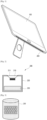
- FIG. 1 is a diagram illustrating an example electronic device 100 according to an embodiment of the disclosure.
- the electronic device 100 according to the embodiment of the disclosure may be implemented as a display apparatus as illustrated in FIG. 1 , e.g. as television, laptop computer, tablet PC, etc.
- the electronic device 100 according to the embodiment of the disclosure is not limited to a display apparatus, and may vary as long as it has a speaker, e.g. Bluetooth speaker and artificial intelligence speaker, etc., and outputs sound therethrough.
- the electronic device 100 according to the embodiment of the disclosure may be a speaker itself.
- the case where the electronic device 100 is a display apparatus will be described by way of example for convenience of description.
- the display apparatus 100 includes a speaker 200.
- the speaker 200 included in the display apparatus 100 of the disclosure may be a slot-type speaker.
- the slot-type speaker may refer, without limitation, to a speaker in which a cross-section area of an opening through which sound is output is smaller than a cross-section of a diaphragm of the speaker.
- the speaker 200 in FIG. 1 is provided in a lower part of the display apparatus 100 and thus a direction of outputting sound is also directed below the electronic device 100.
- the location of the speaker in the display apparatus 100 or the direction of outputting sound of the speaker 200 is not limited to the foregoing.
- the speaker 200 of the disclosure is not limited to the slot-type speaker.
- FIG. 2 is a cross-sectional view of the speaker 200 according to an embodiment of the disclosure.
- the speaker 200 according to the embodiment of the disclosure includes a driver unit (e.g., a driver) 210, an enclosure 220 and an air adsorption member 230.
- a driver unit e.g., a driver
- the driver unit 210 may output sound according to a sound signal input to the driver unit 210.
- the driver unit 210 may be provided in the enclosure 220 or along with the enclosure 220.
- the driver unit 210 may be comprised of a single or plural drivers.
- the driver unit 210 may include a diaphragm 211 and a driving circuit (not shown) to output sound from a sound signal.
- the enclosure 220 may refer, for example, to a structure forming a shape of the speaker, and accommodates the driver unit 210 therein.
- the enclosure 220 may surround a rear side of the driver unit 210.
- the air adsorption member 230 is provided in the enclosure 220.
- the air adsorption member 230 includes a graphene.
- the graphene may refer, for example, to a 2D membrane generated by a planar combination of carbon atoms and has various strengths such as high electron mobility, excellent mechanical strength and transparency.
- the air adsorption member 230 including the graphene adsorbs air in the enclosure 220 when the diaphragm 211 moves toward an inside of the enclosure 220, thereby preventing and/or avoiding a situation in which a sound compliance from being reduced according to a rise in an internal pressure of the enclosure 220. That is, the air adsorption member 230 creates the effect as if the bulk of the enclosure 220 has been substantially improved.
- the air adsorption member 230 may discharge air to an inside of the enclosure 220 when the diaphragm 211 moves toward an outside of the enclosure 220, thereby preventing and/or avoiding a situation in which the sound compliance from being increased according to a drop in pressure.
- FIG. 3 is a diagram illustrating an example structure of the air adsorption member 230 of the speaker 200 according to the embodiment of the disclosure.
- the air adsorption member 230 of the speaker 200 may, for example, be implemented as a graphene sponge extending from a 2D graphene to a 3D structure or as a graphene platelet including several layers of graphene.
- FIG. 3 illustrates an example of the graphene sponge implementing the air adsorption member 230.
- the air adsorption member 230 of the speaker 200 according to the embodiment of the disclosure is implemented as a graphene sponge or graphene platelet, the air adsorption member 230 may have a pore size effective for improving sound compliance through air adsorption and high specific surface area.
- the low-range reproduction capability of the speaker 200 is further improved.
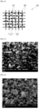
- FIG. 4 is a diagram illustrating an example structure of an air adsorption member 230 of a speaker 200 according to an embodiment of the disclosure.
- the air adsorption member 230 of the speaker 200 includes a scaffold 320 as a structure to which a graphene 310 is attached.
- the scaffold 320 may, for example, have the graphene 310 attached thereto so that the graphene 310 does not freely move within the enclosure 220.
- the scaffold 320 is provided in a grid form.
- a space between grids or a length of each grid may be ununiform.
- the space between the grids of the scaffold 320 is larger than the size of the graphene 310.
- the space (d in FIG. 4 ) between the grids of the scaffold 320 may be larger than a diameter of the particle or powder (a in FIG. 4 ) of the graphene 310.
- the scaffold 320 may be provided, for example, as at least one of melamine foam, cellulose fiber matrix and metal mesh.
- the material of the scaffold 320 is not limited to the foregoing.
- the strength or durability of the air adsorption member 230 of the speaker 200 is improved.
- Various methods are available for attaching the graphene 310 to the scaffold 320.
- the air adsorption member 230 may be provided to attach the powder-type graphene 310 to the scaffold 320. Since the graphene 310 may have a size having a magnitude in nanometers it may be much smaller than the scaffold 320, if the scaffold 320 is dipped in a place where the graphene 310 is provided in the form of powder, the graphene 310 and the scaffold 320 may strongly adhere to each other by van der Waals force, etc.
- an additional process of shaking or kneading the scaffold 320 by hand after putting the scaffold 320 in the place where the graphene 310 is provided in the form of powder may be performed.
- FIGS. 5 and 6 are photographs illustrating an example structure seen through a microscope when the graphene 310 in the form of powder is attached to the scaffold 320.
- FIG. 5 relates to a first part of the air adsorption member 230.
- FIG. 6 relates to a second part of the air adsorption member 230.
- the air adsorption member 230 may be manufactured relatively easily without additional encapsulation process. Since the pore size, specific surface area, density, etc. of the air adsorption member 230 may be controlled by adjusting the space of the scaffold 320 or by varying the size of the powder of the graphene 310, the effect of air adsorption may be maximized and/or improved.
- the air adsorption member 230 may have the graphene 310 attached to the scaffold 320 using a volatile solution in which the graphene 310 is dissolved.
- a volatile solution in which the graphene 310 is dissolved.
- the solution may be applied to the scaffold 320 by being sprinkled on the scaffold 320 or by dipping the scaffold 320 in the solution, and as the volatile solution is volatilized, the graphene 310 is attached to the scaffold 320.
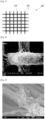
- FIG. 7 is a diagram illustrating an example structure of the air adsorption member 230 that is provided by the foregoing attachment method.
- FIG. 8 is a photograph illustrating an example structure of FIG. 7 seen through a microscope.
- FIG. 9 is a photograph illustrating an example structure of FIG. 7 seen through a microscope.
- FIG. 9 illustrates the example structure of FIG. 7 seen through a microscope equipped with a higher resolution microscope than that used for FIG. 8 .
- the air adsorption member 230 may be manufactured relatively easily. Also, the effect of air adsorption may be maximized and/or improved by controlling the pore size, specific surface area and density of the air adsorption member 230.
- FIG. 10 is a diagram illustrating an example comparison between a graph 1002 which shows a change to a resonant frequency when the quantity of active carbon 1030 as an air adsorption member according to a prior art is increased within a closed-type enclosure 1020, and a graph 1001 which shows a change to a resonant frequency when the quantity of the air adsorption member 1030 including, e.g. graphene platelet (GP) according to the disclosure is increased.
- the rate of increase in bulk is saturated at 20% while, in the case of the air adsorption member 1030 including GP, the resonant frequency is continuously reduced and the rate of increase in bulk is more than 40%.
- the rate of increase in bulk may refer, for example, to the percentage of the effect of increase in bulk of the enclosure 1020 corresponding to the amount of reduction of the resonant frequency.
- the rate of increase in bulk may refer, for example, to the percentage of the effect of substantial increase in bulk through the air adsorption member with respect to the current volume of the enclosure 1020.
- the rate of increase in bulk of the enclosure 1020 is higher than that of the prior art using active carbon, and thus the low-range reproduction capability may be further improved even in the enclosure 1020 with a limited volume.
- FIG. 11 is a diagram including various graphs showing changes to impedance and sound pressure level (SPL) of a prior speaker 1101 including an enclosure with a first volume, a speaker 1102 including the air adsorption member 1130 according to the disclosure within the enclosure with the first volume and a prior speaker 1103 including an enclosure with a second volume larger than the first volume.
- SPL sound pressure level
- the left graph 1110 in FIG. 11 is a graph showing a change to an impedance depending on frequency, with respect to the foregoing three speakers 1101, 1102 and 1103. According to the left graph 1110 in FIG. 11 , it can be shown that a peak frequency of an impedance curve with respect to the speaker 1102 including the air adsorption member 1130 according to the disclosure within the 350cc enclosure is lower than a peak frequency of an impedance curve with respect to the prior speaker 1101 including the 350cc enclosure, and that the degree of reduction of the peak frequency of the impedance curve is similar to the degree of increase of the volume of the enclosure of the prior speak from 350cc to 500cc.
- the right graph 1120 in FIG. 11 shows changes to the SPL according to frequency, with respect to the three speakers 1101, 1102 and 1103.
- the SPL in a low band out of SPL graphs with respect to the speaker 1102 including the air adsorption member 1130 according to the disclosure within the 350cc enclosure has been improved compared to the SPL in a low band of the SPL graphs with respect to the prior speaker 1101 including the 350cc enclosure, and that the degree of improvement of the SPL in the low band is similar to the degree of increase of the volume of the enclosure of the prior speak from 350cc to 500cc.
- the bulk of the enclosure 1020 has been increased by approximately 40% compared to the prior art and therefore the low-range reproduction capability may be further improved even in the enclosure 1020 with a limited volume.
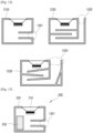
- FIG. 12 is a diagram illustrating various example forms of the enclosure of the speaker according to an embodiment of the disclosure.
- the enclosure of the speaker according to an embodiment of the disclosure may include at least one of openings 1201, 1202, 1203 through which an inside and an outside of the enclosure communicate with each other.
- the speaker according to the embodiment of the disclosure may be implemented as a speaker including open-type enclosures 1210, 1220 and 1230. This is because the graphene included in the air adsorption member of the speaker according to the disclosure may be basically hydrophobic and may be less affected by humidity.
- the speaker according to an embodiment of the disclosure not only applies to a closed-type enclosure but also may be implemented as a speaker including an open-type enclosure, and therefore is not subject to specific limitation of design of the enclosure.
- the disclosure can be implemented through the speaker having an enclosure in various forms, and the degree of freedom is increased in designing the speaker.
- FIG. 13 is a cross-sectional view illustrating an example speaker 200 according to an embodiment of the disclosure.
- the location or direction of arrangement of the air adsorption member 230 there is no specific limitation in the location or direction of arrangement of the air adsorption member 230.
- the speaker 200 according to an embodiment of the disclosure may be arranged in parallel with, or perpendicularly to, the driver unit 210.
- the location or direction of arrangement of the air adsorption member 230 may be decided based on the form or internal structure of the enclosure 220 or the desired degree of effect of air adsorption.
- the effect of air adsorption is adjustable and the degree of freedom is increased in of designing the speaker 200 by adjusting the location of arrangement of the air adsorption member 230.
- a low-range reproduction capability of a speaker of a display apparatus may be improved and the degree of freedom may be increased in designing the speaker.
- the air adsorption member may be manufactured relatively easily without an additional encapsulation process. Also, the effect of air adsorption may be maximized and/or improved by controlling a pore size, specific surface area, density, etc. of the air adsorption member.
- the air adsorption member may be manufactured relatively easily. Also, the effect of air adsorption may be maximized and/or improved by controlling a pore size, specific surface area, density, etc. of the air adsorption member.
- the disclosure may be implemented through various forms of speakers and thus the degree of freedom is increased in designing the speaker.
- the effect of air adsorption is adjustable and the degree of freedom is also increased in designing the speaker by adjusting the location of arrangement of the air adsorption member.
Landscapes
- Physics & Mathematics (AREA)
- Engineering & Computer Science (AREA)
- Acoustics & Sound (AREA)
- Signal Processing (AREA)
- Health & Medical Sciences (AREA)
- Otolaryngology (AREA)
- Details Of Audible-Bandwidth Transducers (AREA)
Description
- The disclosure relates to a speaker and a display apparatus, for example, to a display apparatus including the speaker.
- In recent years, electronic devices including a sound system such as television, Bluetooth speakers and mobile phones are getting slimmer. At the same, there is a growing demand for good sound quality.
Patent document GB 2 551 779 A - Low-range reproduction capability greatly affects sound quality. One of the methods for improving low-range reproduction capability is to provide a large enclosure of a speaker. The larger an enclosure of a speaker is, the more advantageous it is to improve low-range performance because a resonant frequency of a sound system which is determined by an interaction between air within the enclosure and a diaphragm is lowered. That is, if air within the enclosure is modeled as a vibration system with a single degree of freedom, internal volume acts like a spring (hereinafter to be also called the "sound compliance"). If the volume is large, it is modeled as a flexible spring and the resonant frequency is lowered.
- As the enclosure should be large to improve the low-range reproduction capability as above, it is not easy to improve the low-range reproduction capability in a relatively small speaker.
- To address limitations of the sound compliance that is dependent upon the physical volume of the enclosure, a technology using active carbon or zeolite to have an effect of increasing a bulk of sound has been developed. The foregoing technology using active carbon or zeolite improves the sound compliance by discharging, condensing and adsorbing part of air within the enclosure to thereby prevent the sound compliance from being reduced according to a rise in a pressure within the enclosure when a diaphragm moves toward an inside of the enclosure. The foregoing technology has an effect opposite to the above when the diaphragm moves toward an outside of the enclosure and internal pressure of the enclosure is lowered.
- However, as active carbon and zeolite are used in the form of granules (small grains) to maximize the effect of air adsorption, they should be isolated from a driver unit exposed in the enclosure. Also, active carbon and zeolite have less effect of air adsorption in high humidity, and thus they are mainly employed in a closed-type enclosure. If active carbon and zeolite are to be employed in an open-type enclosure, additional measures should be taken to prevent humidity. Also, although the pore size, specific surface area and density of adsorption materials should be controllable to maximize the effect of air adsorption, such control is not easy for zeolite and active carbon in general.
- Embodiments of the disclosure provide a display apparatus including an air adsorption member which may maximize and/or improve the effect of increasing a bulk of sound and may apply to various types of enclosures.
- There is provided a speaker in accordance with claim 1. Other aspects of the invention are set forth in the dependent claims.
- As described above, according to the disclosure, a low-range reproduction capability of a speaker of a display apparatus may be improved and the degree of freedom may be increased in designing the speaker.
-
-
FIG. 1 is a diagram illustrating an example display apparatus according to an embodiment of the disclosure; -
FIG. 2 is a cross-sectional view illustrating an example speaker according to an embodiment of the disclosure; -
FIG. 3 is a diagram illustrating an example structure of an air adsorption member of the speaker according to an embodiment of the disclosure; -
FIG. 4 is a diagram illustrating an example structure of an air adsorption member of a speaker according to an embodiment of the disclosure; -
FIG. 5 is a photograph illustrating an example structure of the air adsorption member of the speaker according to an embodiment of the disclosure; -
FIG. 6 is a photograph illustrating an example structure of the air adsorption member of the speaker according to an embodiment of the disclosure; -
FIG. 7 is a diagram illustrating an example structure of an air adsorption member of a speaker according to an embodiment of the disclosure; -
FIG. 8 is a photograph illustrating an example structure of the air adsorption member of the speaker according to an embodiment of the disclosure; -
FIG. 9 is a photograph illustrating an example structure of the air adsorption member of the speaker according to an embodiment of the disclosure; -
FIG. 10 is a diagram illustrating an effect of an embodiment of the disclosure; -
FIG. 11 is a diagram illustrating an example effect of an embodiment of the disclosure; -
FIG. 12 is a diagram illustrating an example effect of an embodiment of the disclosure; and -
FIG. 13 is a cross-sectional view illustrating an example speaker according to an embodiment of the disclosure. - Below, various example embodiments of the disclosure will be described in greater detail with reference to accompanying drawings. In the drawings, the like reference numerals or signs may refer to elements that perform substantially the same functions, and the size of the respective elements may have been magnified for clarification and convenience of description. However, the technical ideas, configurations and effects of the disclosure are not limited to the configurations or effects described in the embodiments below. Embodiments which are described with reference to the drawings are not mutually exclusive unless otherwise specified and a plurality of embodiments may be selectively combined with each other for implementation. In the course of describing the disclosure, where any detailed description of known art or configuration relating to the disclosure is likely to unnecessarily deviate from substance of the disclosure, such detailed description may be omitted.
- In the embodiments of the disclosure, terms including ordinal numbers such as first and second may be used simply for distinguishing an element from another element. The singular includes the plural unless the context explicitly otherwise requires. In the embodiments of the disclosure, terms "comprise", "include" and "have" should be understood as not excluding the possibility of existence or addition of one or more other characteristics, numbers, steps, operations, elements, parts or a combination of the same. In the embodiments of the disclosure, terms "upper", "top", "lower", "bottom", "left", "right", "above" and "below" are defined on the basis of the drawings, and the shape or location of the elements are not limited by the same. In addition, in the embodiments of the disclosure, the expression "at least one" of a plurality of elements refers to not only all of the plurality of elements but also each or a combination of the same excluding the remainder of the plurality of elements.
-
FIG. 1 is a diagram illustrating an exampleelectronic device 100 according to an embodiment of the disclosure. Theelectronic device 100 according to the embodiment of the disclosure may be implemented as a display apparatus as illustrated inFIG. 1 , e.g. as television, laptop computer, tablet PC, etc. However, theelectronic device 100 according to the embodiment of the disclosure is not limited to a display apparatus, and may vary as long as it has a speaker, e.g. Bluetooth speaker and artificial intelligence speaker, etc., and outputs sound therethrough. Theelectronic device 100 according to the embodiment of the disclosure may be a speaker itself. However, hereinafter, the case where theelectronic device 100 is a display apparatus will be described by way of example for convenience of description. - The
display apparatus 100 according to the embodiment of the disclosure includes aspeaker 200. Thespeaker 200 included in thedisplay apparatus 100 of the disclosure may be a slot-type speaker. The slot-type speaker may refer, without limitation, to a speaker in which a cross-section area of an opening through which sound is output is smaller than a cross-section of a diaphragm of the speaker. Thespeaker 200 inFIG. 1 is provided in a lower part of thedisplay apparatus 100 and thus a direction of outputting sound is also directed below theelectronic device 100. However, the location of the speaker in thedisplay apparatus 100 or the direction of outputting sound of thespeaker 200 is not limited to the foregoing. Also, thespeaker 200 of the disclosure is not limited to the slot-type speaker. -
FIG. 2 is a cross-sectional view of thespeaker 200 according to an embodiment of the disclosure. Thespeaker 200 according to the embodiment of the disclosure includes a driver unit (e.g., a driver) 210, anenclosure 220 and anair adsorption member 230. - The
driver unit 210 may output sound according to a sound signal input to thedriver unit 210. Thedriver unit 210 may be provided in theenclosure 220 or along with theenclosure 220. Thedriver unit 210 may be comprised of a single or plural drivers. Thedriver unit 210 may include adiaphragm 211 and a driving circuit (not shown) to output sound from a sound signal. - The
enclosure 220 may refer, for example, to a structure forming a shape of the speaker, and accommodates thedriver unit 210 therein. Theenclosure 220 may surround a rear side of thedriver unit 210. There is no specific limitation in the shape and material of theenclosure 220. Theair adsorption member 230 is provided in theenclosure 220. Theair adsorption member 230 includes a graphene. The graphene may refer, for example, to a 2D membrane generated by a planar combination of carbon atoms and has various strengths such as high electron mobility, excellent mechanical strength and transparency. Theair adsorption member 230 including the graphene adsorbs air in theenclosure 220 when thediaphragm 211 moves toward an inside of theenclosure 220, thereby preventing and/or avoiding a situation in which a sound compliance from being reduced according to a rise in an internal pressure of theenclosure 220. That is, theair adsorption member 230 creates the effect as if the bulk of theenclosure 220 has been substantially improved. On the other hand, theair adsorption member 230 may discharge air to an inside of theenclosure 220 when thediaphragm 211 moves toward an outside of theenclosure 220, thereby preventing and/or avoiding a situation in which the sound compliance from being increased according to a drop in pressure. - Based on the above, a low-range reproduction capability of the
speaker 200 is improved. -
FIG. 3 is a diagram illustrating an example structure of theair adsorption member 230 of thespeaker 200 according to the embodiment of the disclosure. - The
air adsorption member 230 of thespeaker 200 according to the embodiment of the disclosure may, for example, be implemented as a graphene sponge extending from a 2D graphene to a 3D structure or as a graphene platelet including several layers of graphene.FIG. 3 illustrates an example of the graphene sponge implementing theair adsorption member 230. If theair adsorption member 230 of thespeaker 200 according to the embodiment of the disclosure is implemented as a graphene sponge or graphene platelet, theair adsorption member 230 may have a pore size effective for improving sound compliance through air adsorption and high specific surface area. - Based on the above, the low-range reproduction capability of the
speaker 200 is further improved. -
FIG. 4 is a diagram illustrating an example structure of anair adsorption member 230 of aspeaker 200 according to an embodiment of the disclosure. - The
air adsorption member 230 of thespeaker 200 according to an embodiment of the disclosure includes ascaffold 320 as a structure to which agraphene 310 is attached. Thescaffold 320 may, for example, have thegraphene 310 attached thereto so that thegraphene 310 does not freely move within theenclosure 220. - As illustrated in
FIG. 4 , thescaffold 320 is provided in a grid form. - A space between grids or a length of each grid may be ununiform.
- The space between the grids of the
scaffold 320 is larger than the size of thegraphene 310. For example, if thegraphene 310 attached to thescaffold 320 is in the form of, e.g. particles or powder as inFIG. 4 , the space (d inFIG. 4 ) between the grids of thescaffold 320 may be larger than a diameter of the particle or powder (a inFIG. 4 ) of thegraphene 310. - The
scaffold 320 may be provided, for example, as at least one of melamine foam, cellulose fiber matrix and metal mesh. However, the material of thescaffold 320 is not limited to the foregoing. - Based on the above, the strength or durability of the
air adsorption member 230 of thespeaker 200 is improved. Various methods are available for attaching thegraphene 310 to thescaffold 320. - For example, the
air adsorption member 230 may be provided to attach the powder-type graphene 310 to thescaffold 320. Since thegraphene 310 may have a size having a magnitude in nanometers it may be much smaller than thescaffold 320, if thescaffold 320 is dipped in a place where thegraphene 310 is provided in the form of powder, thegraphene 310 and thescaffold 320 may strongly adhere to each other by van der Waals force, etc. To further increase the contact between thegraphene 310 and thescaffold 320 in the process of adhering thegraphene 310 to thescaffold 320, an additional process of shaking or kneading thescaffold 320 by hand after putting thescaffold 320 in the place where thegraphene 310 is provided in the form of powder may be performed. -
FIGS. 5 and 6 are photographs illustrating an example structure seen through a microscope when thegraphene 310 in the form of powder is attached to thescaffold 320. -
FIG. 5 relates to a first part of theair adsorption member 230. -
FIG. 6 relates to a second part of theair adsorption member 230. - Based on the above, the
air adsorption member 230 may be manufactured relatively easily without additional encapsulation process. Since the pore size, specific surface area, density, etc. of theair adsorption member 230 may be controlled by adjusting the space of thescaffold 320 or by varying the size of the powder of thegraphene 310, the effect of air adsorption may be maximized and/or improved. - As another example of attaching the
graphene 310 to thescaffold 320, theair adsorption member 230 may have thegraphene 310 attached to thescaffold 320 using a volatile solution in which thegraphene 310 is dissolved. For example, after thegraphene 310 is dissolved in a volatile solution, the solution may be applied to thescaffold 320 by being sprinkled on thescaffold 320 or by dipping thescaffold 320 in the solution, and as the volatile solution is volatilized, thegraphene 310 is attached to thescaffold 320. -
FIG. 7 is a diagram illustrating an example structure of theair adsorption member 230 that is provided by the foregoing attachment method. -
FIG. 8 is a photograph illustrating an example structure ofFIG. 7 seen through a microscope. -
FIG. 9 is a photograph illustrating an example structure ofFIG. 7 seen through a microscope.FIG. 9 illustrates the example structure ofFIG. 7 seen through a microscope equipped with a higher resolution microscope than that used forFIG. 8 . - Based on the above, the
air adsorption member 230 may be manufactured relatively easily. Also, the effect of air adsorption may be maximized and/or improved by controlling the pore size, specific surface area and density of theair adsorption member 230. - Hereinafter, the effect of the disclosure will be described in greater detail below with reference to
FIGS. 10 ,11 and12 . -
FIG. 10 is a diagram illustrating an example comparison between agraph 1002 which shows a change to a resonant frequency when the quantity ofactive carbon 1030 as an air adsorption member according to a prior art is increased within a closed-type enclosure 1020, and agraph 1001 which shows a change to a resonant frequency when the quantity of theair adsorption member 1030 including, e.g. graphene platelet (GP) according to the disclosure is increased. In the case of the air adsorption member including active carbon, the rate of increase in bulk is saturated at 20% while, in the case of theair adsorption member 1030 including GP, the resonant frequency is continuously reduced and the rate of increase in bulk is more than 40%. The rate of increase in bulk may refer, for example, to the percentage of the effect of increase in bulk of theenclosure 1020 corresponding to the amount of reduction of the resonant frequency. For example, the rate of increase in bulk may refer, for example, to the percentage of the effect of substantial increase in bulk through the air adsorption member with respect to the current volume of theenclosure 1020. - According to the disclosure, the rate of increase in bulk of the
enclosure 1020 is higher than that of the prior art using active carbon, and thus the low-range reproduction capability may be further improved even in theenclosure 1020 with a limited volume. -
FIG. 11 is a diagram including various graphs showing changes to impedance and sound pressure level (SPL) of aprior speaker 1101 including an enclosure with a first volume, aspeaker 1102 including theair adsorption member 1130 according to the disclosure within the enclosure with the first volume and aprior speaker 1103 including an enclosure with a second volume larger than the first volume. Although there is no specific limitation in the first and second volumes, it will be described hereinafter that the first volume and second volume are 350cc and 500cc, respectively, for convenience of description. Also, it is assumed that theair adsorption member 1130 has been provided by dipping melamine foam in a GP solution and then drying the same. - The
left graph 1110 inFIG. 11 is a graph showing a change to an impedance depending on frequency, with respect to the foregoing threespeakers left graph 1110 inFIG. 11 , it can be shown that a peak frequency of an impedance curve with respect to thespeaker 1102 including theair adsorption member 1130 according to the disclosure within the 350cc enclosure is lower than a peak frequency of an impedance curve with respect to theprior speaker 1101 including the 350cc enclosure, and that the degree of reduction of the peak frequency of the impedance curve is similar to the degree of increase of the volume of the enclosure of the prior speak from 350cc to 500cc. - The
right graph 1120 inFIG. 11 shows changes to the SPL according to frequency, with respect to the threespeakers right graph 1120 inFIG. 11 , it can be shown that the SPL in a low band out of SPL graphs with respect to thespeaker 1102 including theair adsorption member 1130 according to the disclosure within the 350cc enclosure has been improved compared to the SPL in a low band of the SPL graphs with respect to theprior speaker 1101 including the 350cc enclosure, and that the degree of improvement of the SPL in the low band is similar to the degree of increase of the volume of the enclosure of the prior speak from 350cc to 500cc. - That is, according to the embodiment of the disclosure, the bulk of the
enclosure 1020 has been increased by approximately 40% compared to the prior art and therefore the low-range reproduction capability may be further improved even in theenclosure 1020 with a limited volume. -
FIG. 12 is a diagram illustrating various example forms of the enclosure of the speaker according to an embodiment of the disclosure. - As shown therein, the enclosure of the speaker according to an embodiment of the disclosure may include at least one of
openings type enclosures - Based on the above, the disclosure can be implemented through the speaker having an enclosure in various forms, and the degree of freedom is increased in designing the speaker.
-
FIG. 13 is a cross-sectional view illustrating anexample speaker 200 according to an embodiment of the disclosure. - In the
speaker 200 according to the disclosure, there is no specific limitation in the location or direction of arrangement of theair adsorption member 230. For example, thespeaker 200 according to an embodiment of the disclosure may be arranged in parallel with, or perpendicularly to, thedriver unit 210. The location or direction of arrangement of theair adsorption member 230 may be decided based on the form or internal structure of theenclosure 220 or the desired degree of effect of air adsorption. - Based on the above, the effect of air adsorption is adjustable and the degree of freedom is increased in of designing the
speaker 200 by adjusting the location of arrangement of theair adsorption member 230. - As described above, according to the disclosure, a low-range reproduction capability of a speaker of a display apparatus may be improved and the degree of freedom may be increased in designing the speaker.
- Based on the above, low-range reproduction capability of the speaker is improved.
- Based on the above, the strength or durability of the air adsorption member of the speaker is improved.
- Based on the above, the air adsorption member may be manufactured relatively easily without an additional encapsulation process. Also, the effect of air adsorption may be maximized and/or improved by controlling a pore size, specific surface area, density, etc. of the air adsorption member.
- Based on the above, the air adsorption member may be manufactured relatively easily. Also, the effect of air adsorption may be maximized and/or improved by controlling a pore size, specific surface area, density, etc. of the air adsorption member.
- Based on the above, the disclosure may be implemented through various forms of speakers and thus the degree of freedom is increased in designing the speaker.
- Based on the above, the effect of air adsorption is adjustable and the degree of freedom is also increased in designing the speaker by adjusting the location of arrangement of the air adsorption member.
Claims (7)
- A speaker (200) comprising:a driver (210) configured to output sound based on an input sound signal;an enclosure (220) surrounding a rear side of the driver (210); andan air adsorption member (230) comprising graphene (310) provided in the enclosure (220),characterized in that:the air adsorption member (230) comprises a scaffold (320) to which the graphene (310) is attached, andthe scaffold (320) has a grid form, wherein a space between grids of the scaffold (320) have a size larger than a size of the graphene (310).
- The speaker (200) according to claim 1, wherein the scaffold (320) comprises at least one of melamine foam, cellulose fiber matrix or metal mesh.
- The speaker (200) according to claim 1, wherein the air adsorption member (230) comprises the graphene in the form of powder attached to the scaffold.
- The speaker (200) according to claim 1, wherein the graphene (310) of the air adsorption member is attached to the scaffold (320) using a volatile solution in which the graphene (310) is dissolved.
- The speaker (200) according to claim 1, wherein the enclosure (220) of the speaker (200) comprises at least one opening through which an inside of the enclosure (220) and an outside of the enclosure (220) communicate.
- The speaker (200) according to claim 1, wherein the air adsorption member (230) is arranged in parallel with, or perpendicular to, the driver (210).
- A display apparatus (100) comprising:a display; andthe speaker (200) of any preceding claim.
Applications Claiming Priority (2)
| Application Number | Priority Date | Filing Date | Title |
|---|---|---|---|
| KR1020180164657A KR102564273B1 (en) | 2018-12-19 | 2018-12-19 | Display apparatus |
| PCT/KR2019/017913 WO2020130591A1 (en) | 2018-12-19 | 2019-12-17 | Display apparatus |
Publications (3)
| Publication Number | Publication Date |
|---|---|
| EP3857910A1 EP3857910A1 (en) | 2021-08-04 |
| EP3857910A4 EP3857910A4 (en) | 2021-11-17 |
| EP3857910B1 true EP3857910B1 (en) | 2025-01-29 |
Family
ID=71097001
Family Applications (1)
| Application Number | Title | Priority Date | Filing Date |
|---|---|---|---|
| EP19899799.1A Active EP3857910B1 (en) | 2018-12-19 | 2019-12-17 | Speaker and display apparatus |
Country Status (4)
| Country | Link |
|---|---|
| US (1) | US10993019B2 (en) |
| EP (1) | EP3857910B1 (en) |
| KR (1) | KR102564273B1 (en) |
| WO (1) | WO2020130591A1 (en) |
Family Cites Families (15)
| Publication number | Priority date | Publication date | Assignee | Title |
|---|---|---|---|---|
| US20020051552A1 (en) | 1999-12-16 | 2002-05-02 | Koninlijke Philips Electronics N.V. | Dual chamber acoustic enclosure with triple venting using passive radiators |
| KR101115669B1 (en) | 2010-04-28 | 2012-02-16 | 이세룡 | A vibration speaker |
| GB201204170D0 (en) * | 2012-03-09 | 2012-04-25 | Bio Nano Consulting | Cross-linked graphene networks |
| US8794373B1 (en) * | 2013-03-15 | 2014-08-05 | Bose Corporation | Three-dimensional air-adsorbing structure |
| KR101502269B1 (en) | 2013-03-21 | 2015-03-13 | (주) 모토텍 | Speaker device |
| DE102013210696A1 (en) | 2013-06-07 | 2014-12-11 | Fraunhofer-Gesellschaft zur Förderung der angewandten Forschung e.V. | Acoustic system with a housing with adsorbing powder |
| JP5490957B1 (en) * | 2013-10-25 | 2014-05-14 | 清二 加川 | Heat dissipation film, and method and apparatus for manufacturing the same |
| US9850592B2 (en) * | 2014-07-21 | 2017-12-26 | Research & Business Foundation Sungkyunkwan University | Complex plating film formed using multi-layer graphene-coated metal particles through electric explosion and method of manufacturing the complex plating film |
| KR101645621B1 (en) | 2014-12-10 | 2016-08-08 | 한국과학기술원 | Graphene thermoacoustic speaker and manufacturing method thereof |
| US10349167B2 (en) * | 2015-05-18 | 2019-07-09 | Apple Inc. | Audio speaker with back volume containing adsorptive material |
| US10244308B2 (en) * | 2015-08-27 | 2019-03-26 | Apple Inc. | Audio speaker having a rigid adsorptive insert |
| KR101709078B1 (en) | 2015-12-31 | 2017-02-23 | 주식회사 이엠텍 | Micro-speaker having an air adsorbent |
| GB2551779A (en) * | 2016-06-30 | 2018-01-03 | Nokia Technologies Oy | An apparatus, method and computer program for audio module use in an electronic device |
| CN207589169U (en) | 2017-12-11 | 2018-07-06 | 广东欧珀移动通信有限公司 | Speaker assembly and mobile terminal |
| US11832050B2 (en) * | 2018-09-19 | 2023-11-28 | Apple Inc. | Zeolitic material for improving loudspeaker performance |
-
2018
- 2018-12-19 KR KR1020180164657A patent/KR102564273B1/en active Active
-
2019
- 2019-12-11 US US16/710,361 patent/US10993019B2/en active Active
- 2019-12-17 WO PCT/KR2019/017913 patent/WO2020130591A1/en not_active Ceased
- 2019-12-17 EP EP19899799.1A patent/EP3857910B1/en active Active
Also Published As
| Publication number | Publication date |
|---|---|
| EP3857910A1 (en) | 2021-08-04 |
| EP3857910A4 (en) | 2021-11-17 |
| KR102564273B1 (en) | 2023-08-07 |
| KR20200076022A (en) | 2020-06-29 |
| US10993019B2 (en) | 2021-04-27 |
| US20200204907A1 (en) | 2020-06-25 |
| WO2020130591A1 (en) | 2020-06-25 |
Similar Documents
| Publication | Publication Date | Title |
|---|---|---|
| US11647324B2 (en) | Audio speaker having a rigid adsorptive insert | |
| CN107534808B (en) | Gas Adsorption Matrix Structure and Acoustic Device | |
| US8292023B2 (en) | Enclosing adsorbent material | |
| US10484769B2 (en) | Speaker box | |
| US8565463B2 (en) | Loudspeaker system | |
| CN113474081B (en) | Cavity and active area | |
| WO2012059814A2 (en) | Electrostatic loudspeaker system | |
| CN113645537A (en) | Audio speaker with back cavity containing absorbent material | |
| US20210144465A1 (en) | Coating for improving loudspeaker sound quality | |
| WO2005099300A1 (en) | Speaker device | |
| JPWO2006104103A1 (en) | Speaker device | |
| KR102234407B1 (en) | Acoustic system having a housing with adsorbent powder | |
| EP3166338A1 (en) | An acoustic apparatus and associated methods | |
| US20210258705A1 (en) | Acoustical protector for audio devices and audio device provided with said protector | |
| US10993019B2 (en) | Display apparatus | |
| CN205726289U (en) | Headphones with dynamic piezo dual audio speakers | |
| JP2009188516A (en) | Electrostatic loudspeaker | |
| JP4643626B2 (en) | Speaker device | |
| JP2020088711A (en) | Electro-acoustic transducer | |
| CN112188373B (en) | Speakers and Electronic Equipment | |
| KR102775777B1 (en) | Sound device | |
| KR102306965B1 (en) | Flat Panel Speaker | |
| TW201127082A (en) | Tuner for adjusting acoustic compliance and micro-speaker having the same |
Legal Events
| Date | Code | Title | Description |
|---|---|---|---|
| STAA | Information on the status of an ep patent application or granted ep patent |
Free format text: STATUS: THE INTERNATIONAL PUBLICATION HAS BEEN MADE |
|
| PUAI | Public reference made under article 153(3) epc to a published international application that has entered the european phase |
Free format text: ORIGINAL CODE: 0009012 |
|
| STAA | Information on the status of an ep patent application or granted ep patent |
Free format text: STATUS: REQUEST FOR EXAMINATION WAS MADE |
|
| 17P | Request for examination filed |
Effective date: 20210428 |
|
| AK | Designated contracting states |
Kind code of ref document: A1 Designated state(s): AL AT BE BG CH CY CZ DE DK EE ES FI FR GB GR HR HU IE IS IT LI LT LU LV MC MK MT NL NO PL PT RO RS SE SI SK SM TR |
|
| A4 | Supplementary search report drawn up and despatched |
Effective date: 20211015 |
|
| RIC1 | Information provided on ipc code assigned before grant |
Ipc: H04R 1/28 20060101AFI20211011BHEP |
|
| DAV | Request for validation of the european patent (deleted) | ||
| DAX | Request for extension of the european patent (deleted) | ||
| STAA | Information on the status of an ep patent application or granted ep patent |
Free format text: STATUS: EXAMINATION IS IN PROGRESS |
|
| 17Q | First examination report despatched |
Effective date: 20230329 |
|
| GRAP | Despatch of communication of intention to grant a patent |
Free format text: ORIGINAL CODE: EPIDOSNIGR1 |
|
| STAA | Information on the status of an ep patent application or granted ep patent |
Free format text: STATUS: GRANT OF PATENT IS INTENDED |
|
| INTG | Intention to grant announced |
Effective date: 20240705 |
|
| GRAS | Grant fee paid |
Free format text: ORIGINAL CODE: EPIDOSNIGR3 |
|
| GRAA | (expected) grant |
Free format text: ORIGINAL CODE: 0009210 |
|
| STAA | Information on the status of an ep patent application or granted ep patent |
Free format text: STATUS: THE PATENT HAS BEEN GRANTED |
|
| AK | Designated contracting states |
Kind code of ref document: B1 Designated state(s): AL AT BE BG CH CY CZ DE DK EE ES FI FR GB GR HR HU IE IS IT LI LT LU LV MC MK MT NL NO PL PT RO RS SE SI SK SM TR |
|
| REG | Reference to a national code |
Ref country code: GB Ref legal event code: FG4D |
|
| REG | Reference to a national code |
Ref country code: CH Ref legal event code: EP |
|
| REG | Reference to a national code |
Ref country code: DE Ref legal event code: R096 Ref document number: 602019065525 Country of ref document: DE |
|
| REG | Reference to a national code |
Ref country code: IE Ref legal event code: FG4D |
|
| REG | Reference to a national code |
Ref country code: NL Ref legal event code: MP Effective date: 20250129 |
|
| PG25 | Lapsed in a contracting state [announced via postgrant information from national office to epo] |
Ref country code: NL Free format text: LAPSE BECAUSE OF FAILURE TO SUBMIT A TRANSLATION OF THE DESCRIPTION OR TO PAY THE FEE WITHIN THE PRESCRIBED TIME-LIMIT Effective date: 20250129 |
|
| PG25 | Lapsed in a contracting state [announced via postgrant information from national office to epo] |
Ref country code: RS Free format text: LAPSE BECAUSE OF FAILURE TO SUBMIT A TRANSLATION OF THE DESCRIPTION OR TO PAY THE FEE WITHIN THE PRESCRIBED TIME-LIMIT Effective date: 20250429 |
|
| PG25 | Lapsed in a contracting state [announced via postgrant information from national office to epo] |
Ref country code: FI Free format text: LAPSE BECAUSE OF FAILURE TO SUBMIT A TRANSLATION OF THE DESCRIPTION OR TO PAY THE FEE WITHIN THE PRESCRIBED TIME-LIMIT Effective date: 20250129 |
|
| PG25 | Lapsed in a contracting state [announced via postgrant information from national office to epo] |
Ref country code: PL Free format text: LAPSE BECAUSE OF FAILURE TO SUBMIT A TRANSLATION OF THE DESCRIPTION OR TO PAY THE FEE WITHIN THE PRESCRIBED TIME-LIMIT Effective date: 20250129 |
|
| PG25 | Lapsed in a contracting state [announced via postgrant information from national office to epo] |
Ref country code: ES Free format text: LAPSE BECAUSE OF FAILURE TO SUBMIT A TRANSLATION OF THE DESCRIPTION OR TO PAY THE FEE WITHIN THE PRESCRIBED TIME-LIMIT Effective date: 20250129 |
|
| REG | Reference to a national code |
Ref country code: LT Ref legal event code: MG9D |
|
| PG25 | Lapsed in a contracting state [announced via postgrant information from national office to epo] |
Ref country code: IS Free format text: LAPSE BECAUSE OF FAILURE TO SUBMIT A TRANSLATION OF THE DESCRIPTION OR TO PAY THE FEE WITHIN THE PRESCRIBED TIME-LIMIT Effective date: 20250529 Ref country code: NO Free format text: LAPSE BECAUSE OF FAILURE TO SUBMIT A TRANSLATION OF THE DESCRIPTION OR TO PAY THE FEE WITHIN THE PRESCRIBED TIME-LIMIT Effective date: 20250429 |
|
| REG | Reference to a national code |
Ref country code: AT Ref legal event code: MK05 Ref document number: 1764594 Country of ref document: AT Kind code of ref document: T Effective date: 20250129 |
|
| PG25 | Lapsed in a contracting state [announced via postgrant information from national office to epo] |
Ref country code: HR Free format text: LAPSE BECAUSE OF FAILURE TO SUBMIT A TRANSLATION OF THE DESCRIPTION OR TO PAY THE FEE WITHIN THE PRESCRIBED TIME-LIMIT Effective date: 20250129 |
|
| PG25 | Lapsed in a contracting state [announced via postgrant information from national office to epo] |
Ref country code: LV Free format text: LAPSE BECAUSE OF FAILURE TO SUBMIT A TRANSLATION OF THE DESCRIPTION OR TO PAY THE FEE WITHIN THE PRESCRIBED TIME-LIMIT Effective date: 20250129 Ref country code: PT Free format text: LAPSE BECAUSE OF FAILURE TO SUBMIT A TRANSLATION OF THE DESCRIPTION OR TO PAY THE FEE WITHIN THE PRESCRIBED TIME-LIMIT Effective date: 20250529 |
|
| PG25 | Lapsed in a contracting state [announced via postgrant information from national office to epo] |
Ref country code: GR Free format text: LAPSE BECAUSE OF FAILURE TO SUBMIT A TRANSLATION OF THE DESCRIPTION OR TO PAY THE FEE WITHIN THE PRESCRIBED TIME-LIMIT Effective date: 20250430 Ref country code: BG Free format text: LAPSE BECAUSE OF FAILURE TO SUBMIT A TRANSLATION OF THE DESCRIPTION OR TO PAY THE FEE WITHIN THE PRESCRIBED TIME-LIMIT Effective date: 20250129 |
|
| PG25 | Lapsed in a contracting state [announced via postgrant information from national office to epo] |
Ref country code: AT Free format text: LAPSE BECAUSE OF FAILURE TO SUBMIT A TRANSLATION OF THE DESCRIPTION OR TO PAY THE FEE WITHIN THE PRESCRIBED TIME-LIMIT Effective date: 20250129 |
|
| PG25 | Lapsed in a contracting state [announced via postgrant information from national office to epo] |
Ref country code: SE Free format text: LAPSE BECAUSE OF FAILURE TO SUBMIT A TRANSLATION OF THE DESCRIPTION OR TO PAY THE FEE WITHIN THE PRESCRIBED TIME-LIMIT Effective date: 20250129 |
|
| PG25 | Lapsed in a contracting state [announced via postgrant information from national office to epo] |
Ref country code: SM Free format text: LAPSE BECAUSE OF FAILURE TO SUBMIT A TRANSLATION OF THE DESCRIPTION OR TO PAY THE FEE WITHIN THE PRESCRIBED TIME-LIMIT Effective date: 20250129 |
|
| PG25 | Lapsed in a contracting state [announced via postgrant information from national office to epo] |
Ref country code: DK Free format text: LAPSE BECAUSE OF FAILURE TO SUBMIT A TRANSLATION OF THE DESCRIPTION OR TO PAY THE FEE WITHIN THE PRESCRIBED TIME-LIMIT Effective date: 20250129 |
|
| PG25 | Lapsed in a contracting state [announced via postgrant information from national office to epo] |
Ref country code: IT Free format text: LAPSE BECAUSE OF FAILURE TO SUBMIT A TRANSLATION OF THE DESCRIPTION OR TO PAY THE FEE WITHIN THE PRESCRIBED TIME-LIMIT Effective date: 20250129 |
|
| PG25 | Lapsed in a contracting state [announced via postgrant information from national office to epo] |
Ref country code: EE Free format text: LAPSE BECAUSE OF FAILURE TO SUBMIT A TRANSLATION OF THE DESCRIPTION OR TO PAY THE FEE WITHIN THE PRESCRIBED TIME-LIMIT Effective date: 20250129 Ref country code: CZ Free format text: LAPSE BECAUSE OF FAILURE TO SUBMIT A TRANSLATION OF THE DESCRIPTION OR TO PAY THE FEE WITHIN THE PRESCRIBED TIME-LIMIT Effective date: 20250129 |
|
| PG25 | Lapsed in a contracting state [announced via postgrant information from national office to epo] |
Ref country code: RO Free format text: LAPSE BECAUSE OF FAILURE TO SUBMIT A TRANSLATION OF THE DESCRIPTION OR TO PAY THE FEE WITHIN THE PRESCRIBED TIME-LIMIT Effective date: 20250129 |
|
| PG25 | Lapsed in a contracting state [announced via postgrant information from national office to epo] |
Ref country code: SK Free format text: LAPSE BECAUSE OF FAILURE TO SUBMIT A TRANSLATION OF THE DESCRIPTION OR TO PAY THE FEE WITHIN THE PRESCRIBED TIME-LIMIT Effective date: 20250129 |
|
| REG | Reference to a national code |
Ref country code: DE Ref legal event code: R097 Ref document number: 602019065525 Country of ref document: DE |
|
| PLBE | No opposition filed within time limit |
Free format text: ORIGINAL CODE: 0009261 |
|
| STAA | Information on the status of an ep patent application or granted ep patent |
Free format text: STATUS: NO OPPOSITION FILED WITHIN TIME LIMIT |
|
| REG | Reference to a national code |
Ref country code: CH Ref legal event code: L10 Free format text: ST27 STATUS EVENT CODE: U-0-0-L10-L00 (AS PROVIDED BY THE NATIONAL OFFICE) Effective date: 20251210 |
|
| 26N | No opposition filed |
Effective date: 20251030 |
|
| PGFP | Annual fee paid to national office [announced via postgrant information from national office to epo] |
Ref country code: DE Payment date: 20251120 Year of fee payment: 7 |
|
| PG25 | Lapsed in a contracting state [announced via postgrant information from national office to epo] |
Ref country code: LT Free format text: LAPSE BECAUSE OF FAILURE TO SUBMIT A TRANSLATION OF THE DESCRIPTION OR TO PAY THE FEE WITHIN THE PRESCRIBED TIME-LIMIT Effective date: 20250129 |
|
| PG25 | Lapsed in a contracting state [announced via postgrant information from national office to epo] |
Ref country code: MC Free format text: LAPSE BECAUSE OF FAILURE TO SUBMIT A TRANSLATION OF THE DESCRIPTION OR TO PAY THE FEE WITHIN THE PRESCRIBED TIME-LIMIT Effective date: 20250129 |
|
| REG | Reference to a national code |
Ref country code: CH Ref legal event code: H13 Free format text: ST27 STATUS EVENT CODE: U-0-0-H10-H13 (AS PROVIDED BY THE NATIONAL OFFICE) Effective date: 20260723 |