EP3857206B1 - Spectrophotometer for use in explosive atmospheres - Google Patents
Spectrophotometer for use in explosive atmospheres Download PDFInfo
- Publication number
- EP3857206B1 EP3857206B1 EP19868092.8A EP19868092A EP3857206B1 EP 3857206 B1 EP3857206 B1 EP 3857206B1 EP 19868092 A EP19868092 A EP 19868092A EP 3857206 B1 EP3857206 B1 EP 3857206B1
- Authority
- EP
- European Patent Office
- Prior art keywords
- spectrophotometer
- fluid
- light pipe
- optical block
- compartment
- Prior art date
- Legal status (The legal status is an assumption and is not a legal conclusion. Google has not performed a legal analysis and makes no representation as to the accuracy of the status listed.)
- Active
Links
Images




Classifications
-
- G—PHYSICS
- G01—MEASURING; TESTING
- G01J—MEASUREMENT OF INTENSITY, VELOCITY, SPECTRAL CONTENT, POLARISATION, PHASE OR PULSE CHARACTERISTICS OF INFRARED, VISIBLE OR ULTRAVIOLET LIGHT; COLORIMETRY; RADIATION PYROMETRY
- G01J3/00—Spectrometry; Spectrophotometry; Monochromators; Measuring colours
- G01J3/02—Details
- G01J3/0205—Optical elements not provided otherwise, e.g. optical manifolds, diffusers, windows
- G01J3/0218—Optical elements not provided otherwise, e.g. optical manifolds, diffusers, windows using optical fibers
-
- G—PHYSICS
- G01—MEASURING; TESTING
- G01J—MEASUREMENT OF INTENSITY, VELOCITY, SPECTRAL CONTENT, POLARISATION, PHASE OR PULSE CHARACTERISTICS OF INFRARED, VISIBLE OR ULTRAVIOLET LIGHT; COLORIMETRY; RADIATION PYROMETRY
- G01J3/00—Spectrometry; Spectrophotometry; Monochromators; Measuring colours
- G01J3/02—Details
- G01J3/0286—Constructional arrangements for compensating for fluctuations caused by temperature, humidity or pressure, or using cooling or temperature stabilization of parts of the device; Controlling the atmosphere inside a spectrometer, e.g. vacuum
-
- G—PHYSICS
- G01—MEASURING; TESTING
- G01J—MEASUREMENT OF INTENSITY, VELOCITY, SPECTRAL CONTENT, POLARISATION, PHASE OR PULSE CHARACTERISTICS OF INFRARED, VISIBLE OR ULTRAVIOLET LIGHT; COLORIMETRY; RADIATION PYROMETRY
- G01J3/00—Spectrometry; Spectrophotometry; Monochromators; Measuring colours
- G01J3/02—Details
- G01J3/0291—Housings; Spectrometer accessories; Spatial arrangement of elements, e.g. folded path arrangements
-
- G—PHYSICS
- G01—MEASURING; TESTING
- G01J—MEASUREMENT OF INTENSITY, VELOCITY, SPECTRAL CONTENT, POLARISATION, PHASE OR PULSE CHARACTERISTICS OF INFRARED, VISIBLE OR ULTRAVIOLET LIGHT; COLORIMETRY; RADIATION PYROMETRY
- G01J3/00—Spectrometry; Spectrophotometry; Monochromators; Measuring colours
- G01J3/46—Measurement of colour; Colour measuring devices, e.g. colorimeters
- G01J3/50—Measurement of colour; Colour measuring devices, e.g. colorimeters using electric radiation detectors
-
- G—PHYSICS
- G01—MEASURING; TESTING
- G01N—INVESTIGATING OR ANALYSING MATERIALS BY DETERMINING THEIR CHEMICAL OR PHYSICAL PROPERTIES
- G01N21/00—Investigating or analysing materials by the use of optical means, i.e. using sub-millimetre waves, infrared, visible or ultraviolet light
- G01N21/17—Systems in which incident light is modified in accordance with the properties of the material investigated
- G01N21/25—Colour; Spectral properties, i.e. comparison of effect of material on the light at two or more different wavelengths or wavelength bands
- G01N21/251—Colorimeters; Construction thereof
-
- G—PHYSICS
- G01—MEASURING; TESTING
- G01N—INVESTIGATING OR ANALYSING MATERIALS BY DETERMINING THEIR CHEMICAL OR PHYSICAL PROPERTIES
- G01N21/00—Investigating or analysing materials by the use of optical means, i.e. using sub-millimetre waves, infrared, visible or ultraviolet light
- G01N21/17—Systems in which incident light is modified in accordance with the properties of the material investigated
- G01N21/25—Colour; Spectral properties, i.e. comparison of effect of material on the light at two or more different wavelengths or wavelength bands
- G01N21/255—Details, e.g. use of specially adapted sources, lighting or optical systems
-
- G—PHYSICS
- G01—MEASURING; TESTING
- G01N—INVESTIGATING OR ANALYSING MATERIALS BY DETERMINING THEIR CHEMICAL OR PHYSICAL PROPERTIES
- G01N21/00—Investigating or analysing materials by the use of optical means, i.e. using sub-millimetre waves, infrared, visible or ultraviolet light
- G01N21/17—Systems in which incident light is modified in accordance with the properties of the material investigated
- G01N21/25—Colour; Spectral properties, i.e. comparison of effect of material on the light at two or more different wavelengths or wavelength bands
- G01N21/27—Colour; Spectral properties, i.e. comparison of effect of material on the light at two or more different wavelengths or wavelength bands using photo-electric detection ; circuits for computing concentration
- G01N21/274—Calibration, base line adjustment, drift correction
-
- G—PHYSICS
- G01—MEASURING; TESTING
- G01N—INVESTIGATING OR ANALYSING MATERIALS BY DETERMINING THEIR CHEMICAL OR PHYSICAL PROPERTIES
- G01N21/00—Investigating or analysing materials by the use of optical means, i.e. using sub-millimetre waves, infrared, visible or ultraviolet light
- G01N21/75—Systems in which material is subjected to a chemical reaction, the progress or the result of the reaction being investigated
- G01N21/77—Systems in which material is subjected to a chemical reaction, the progress or the result of the reaction being investigated by observing the effect on a chemical indicator
- G01N21/78—Systems in which material is subjected to a chemical reaction, the progress or the result of the reaction being investigated by observing the effect on a chemical indicator producing a change of colour
-
- G—PHYSICS
- G01—MEASURING; TESTING
- G01N—INVESTIGATING OR ANALYSING MATERIALS BY DETERMINING THEIR CHEMICAL OR PHYSICAL PROPERTIES
- G01N33/00—Investigating or analysing materials by specific methods not covered by groups G01N1/00 - G01N31/00
- G01N33/18—Water
- G01N33/1886—Water using probes, e.g. submersible probes, buoys
-
- G—PHYSICS
- G01—MEASURING; TESTING
- G01N—INVESTIGATING OR ANALYSING MATERIALS BY DETERMINING THEIR CHEMICAL OR PHYSICAL PROPERTIES
- G01N21/00—Investigating or analysing materials by the use of optical means, i.e. using sub-millimetre waves, infrared, visible or ultraviolet light
- G01N21/75—Systems in which material is subjected to a chemical reaction, the progress or the result of the reaction being investigated
- G01N21/77—Systems in which material is subjected to a chemical reaction, the progress or the result of the reaction being investigated by observing the effect on a chemical indicator
- G01N2021/7756—Sensor type
- G01N2021/7763—Sample through flow
-
- G—PHYSICS
- G01—MEASURING; TESTING
- G01N—INVESTIGATING OR ANALYSING MATERIALS BY DETERMINING THEIR CHEMICAL OR PHYSICAL PROPERTIES
- G01N2201/00—Features of devices classified in G01N21/00
- G01N2201/02—Mechanical
- G01N2201/023—Controlling conditions in casing
- G01N2201/0236—Explosion proof
Definitions
- the application relates to spectrophotometers, and particularly to spectrophotometers for use in explosive atmospheres.
- a spectrophotometer measures light transmission through a sample fluid at a particular wavelength of light.
- a reagent added to the fluid changes the color of the fluid, thus changing the transmission of light through the fluid based on the presence of a material to be detected.
- a colorimeter is a type of spectrophotometer operating a visible wavelength.
- US6888636B2 describes an apparatus for inspection of fluids having a fluid analysis cell with a cavity therein enclosed by two light transmitting windows and having a spacer member fixedly positioned therebetween which provides a fluid analysis chamber of fixed pathlength where fluid flows by the windows and preferably wherein the flow laminar and at a uniform shear to provide accurate color measurements.
- Light transmitting and receiving probes are positioned adj acent to the viewing windows and wherein the faces of each probe are contiguous and flush with the viewing windows but are separated from the flow by the viewing windows, so that transmission measurements can be taken orthogonal to the direction of flow.
- the apparatus is particularly useful in the manufacture of dispersions and tints used in the manufacture of paints, so that the color of material being made can be accurately matched to a standard color in the wet state with confidence that the color will match in the dry state.
- the invention provides a photospectrometer according to claim 1.
- At least one of the first light pipe or the second light pipe includes a push to connect (PTC) connector to mechanically coupled the at least one of the first light pipe or the second light pipe to the optical block.
- PTC push to connect
- the spectrophotometer further includes another light pipe to illuminate the fluid sample in the optical block with a back light for visual observation of a presence and color of the fluid sample.
- the spectrophotometer further includes another light pipe to illuminate the fluid sample in the optical block with a calibration light to automatically determine a presence of fluid in the optical block.
- the at least one light source includes a visible light.
- the spectrophotometer includes a colorimeter, and wherein the at least one optical detector measures an amplitude of light at a particular color.
- the at least one optical detector measures an amplitude of light at a particular color of light transmission through the fluid sample disposed in the optical block and wherein the fluid sample is combined with at least a first reagent.
- the spectrophotometer measures a level of chlorine in a ship's ballast water.
- a spectrophotometer for use in an explosive atmosphere includes a purged compartment which has disposed within, at least one light source, and at least one detector.
- a non-purged compartment has disposed within, an optical block having at least one fluid connection port.
- a first light pipe is optically coupled between the at least one light source and the optical block.
- a second light pipe is optically coupled between the optical block and the at least one detector.
- the non-purged compartment is adapted to perform spectrophotometry of a fluid sample disposed within a sample container in the optical block, and the purged compartment is electrically isolated from the non-purged compartment.
- At least one of the first light pipe or the second light pipe include an acrylic plastic.
- At least one of the first light pipe or the second light pipe include a PTC connector to mechanically coupled the at least one of the first light pipe or the second light pipe to the optical block.
- the spectrophotometer further includes another light pipe to illuminate the fluid sample in the optical block with a back light for visual observation of a presence and color of the fluid sample.
- the spectrophotometer further including another light pipe to illuminate the fluid sample in the optical block with a calibration light to automatically determine a presence of fluid in the optical block.
- the at least one light source includes a visible light.
- the spectrophotometer includes a colorimeter, and wherein the detector measures an amplitude of light at a particular color.
- the detector measures an amplitude of light at a particular color of light transmission through the fluid sample disposed in the optical block and wherein the fluid sample is combined with at least a first reagent.
- the spectrophotometer measures a level of chlorine in a ship's ballast water.
- a method of measuring a presence or concentration of an organic or inorganic compound in a fluid in an explosive atmosphere includes: providing a spectrophotometer including: a purged compartment having disposed within: at least one light source, at least one detector, a non-purged compartment having disposed within: an optical block having at least one fluid connection port, a first light pipe optically coupled between the at least one light source and the optical block, and a second light pipe optically coupled between the optical block and the at least one detector; purging the purged compartment with a positive air pressure; filling a sample container with the fluid to be tested; injecting at least one reagent into the fluid; measuring an amount transmission of a light from the light source transmitted through the fluid and reagent via the first light pipe and the second light pipe to the detector; and determining the presence or concentration of the organic or inorganic compound in the fluid in the explosive atmosphere based on the amount transmission of the light.
- the step of injecting includes injecting at least one reagent for a detection of chlorine into the fluid, and the step of determining the presence or concentration includes determining the presence or concentration of chlorine in a ship's ballast water.
- the step of injecting includes injecting at least one reagent to determine the presence or concentration of a micro-organism into the fluid, and the step of determining the presence or concentration includes determining the presence or concentration of the micro-organism in the fluid.
- the step of injecting includes injecting at least one reagent for to determine the presence or concentration of a heavy metal into the fluid, and the step of determining the presence or concentration includes determining the presence or concentration of the heavy metal in the fluid.
- Light pipe - The light pipe transmits light with a substantially minimal wavelength shift or wavelength distortion of the transmitted light.
- Light pipes for the spectrophotometer according to the invention are formed or cut from an acrylic plastic.
- a light pipe is distinguished from, and does not include typical silica based glass fiber optic cables.
- a spectrophotometer measures light transmission at a particular wavelength of light through a sample of a fluid.
- a reagent added to the fluid changes the color of the fluid in response to the presence of certain materials (including certain organic or inorganic materials or substances) in the fluid, thus changing the transmission of light through the fluid based on the presence of a material to be detected.
- a colorimeter is a type of spectrophotometer operating a visible wavelength.
- FLUID CONTENT MONITOR assigned to HF Scientific, the same assignee of this Application, describes an exemplary colorimeter as a fluid content monitor including a cuvette, a colorimeter adapted to generate a signal indicative of contents of a fluid sample contained in the cuvette, a container for holding a reagent, and a pump assembly for delivering reagent from the container to the cuvette.
- the '068 patent is incorporated herein in its entirety for all purposes.
- Reagents are available, in development, or contemplated for the detection of a vast variety of organic and inorganic materials, including microorganisms, metals, alloys, and compounds. These reagents are typically injected into a fluid sample to determine a presence or concentration of the organic and inorganic material in the fluid.
- Such fluid testing is common in industrial environments, such as to test the water quality or for particular contaminants in water including waste water, runoff water (e.g. for pesticides), and ballast water (e.g. for chlorine levels in a ship's ballast water).
- waste water e.g. for pesticides
- ballast water e.g. for chlorine levels in a ship's ballast water
- fluid measuring sensors experience undesired refraction of light transmitted through a fluid where coupled via typical silica based fiber optic cables from a light source to a fluid light transmission sample and to a corresponding detector to measure the transmitted light through the fluid sample.
- the measurement can be distorted by the light refraction of the fiber optic cables as well as other optical properties of typical silica based fiber optic cables which can cause a shift of wavelength or otherwise introduce a wavelength dependent distortion of the light transmitted for a light source through a fluid sample under test and then to a light detector.
- a spectrophotometer using acrylic plastic light pipes pipes solved the problems of wavelength distortion imparted by typical fiber optic cables (e.g. single mode and multimode glass fibers).
- a spectrophotometer was realized substantially without wavelength distortion that can have separate compartments for electronics components, such as the light source and light detector and for chemistry "wet testing" of a fluid sample under test.
- such light pipes are typically less costly than corresponding lengths of terminated silica based fiber optic cables.
- the electronics compartment of the spectrophotometer can be built as a purged compartment.
- the electronics compartment can be pressurized at a positive air pressure to purge any explosive gas or air suspended particulate matter otherwise present in the explosive atmosphere.
- an optical mount to perform the wet chemistry can be present in a non-purged compartment about adj acent to the purged electronics compartment.
- FIG. 1 is a drawing of an exemplary spectrophotometer 100 for use in explosive atmospheres according to the Application.
- the electronics compartment 120 is purged of environmental air by a source of non-explosive pressurized gas.
- the pressurized gas is typically pressurized air, such as, for example from an air hose connection to an inhouse or shipboard pneumatic air source. Any suitable gas can also be used, such as, for example, any suitable inert gas.
- the wet chemistry is performed in the non-purged testing compartment 130. While referred to as known in the art as the "wet" or "wet chemistry" side, the testing compartment 130 is substantially dry, and the water or fluid to be tested is pumped into a test container in an optical mount 155. In the exemplary embodiment of FIG.
- the purged electronics compartment 120 is a second enclosure built into a larger outer industrial enclosure, the part of the outer overall enclosure not contained with the inner box of the electronics compartment 120, being defined as the testing compartment 130.
- the electronics compartment 120 can be purged of the air from the explosive environment, typically by a positive pressure from a non-explosive air source, it is unimportant how the two compartments are constructed.
- a cost effective and efficient system and method to pressurize the electronics compartment 120 is by use of a positive pressure non-explosive air source which maintains a pressure within the electronics compartment 120 over the pressure of the surrounding explosive environment, while allowing a slight outflow of the non-explosive pressurized air from the electronics compartment 120 into the surrounding explosive environment.
- removing possible electrical ignition sources from the testing compartment 130 further configures an instrument for permissible use in an explosive environment.
- flexible light pipes are used to electrically isolate the testing compartment, while transmitting to and receiving light from the optical mount in the testing compartment.
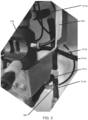
- FIG. 2A shows a drawing of an exemplary optical mount assembly 150, and its associated fluid, pneumatic, and flexible light pipe connections.
- a light pipe here a flexible light pipe 201a, transmits light from a light source in the electronics compartment 120 to the optical mount 155 to illuminate a fluid under test in a transparent or translucent test container in the optical mount 155 in the testing compartment 130.
- the backlight from back light flexible light pipe 201a is mechanically and optically coupled into the optical mount 155 at termination point 279, FIG. 2B .
- Another flexible light pipe 201d conveys light transmitted through the sample container (and thus, through the fluid under test) to an optical detector in the electronics compartment 120.
- light pipes are part no. IF 101H-0-17 having a 2.0mm diameter optical fiber (lightguide), available from Industrial Fiber Optics of Tempe, AZ.
- the optical core of the exemplary light pipes is a Super Eska TM with a polyethylene cable jacket. The exact type or circular, square, or rectangular cross section shape and dimensions of any suitable light pipe is unimportant, and any suitable light pipe can be used.
- the optional backlight illuminates the fluid in the test container so that an observer can see the fluid and the approximate color of the fluid through one or more windows in the spectrophotometer 100 cabinet.
- An optional level calibration light provides a light in a physical position on the optical mount 155, such that electronics in the electronics compartment can determine when the fluid test container is full of a fluid under test. While such features can be controlled by hardwired logic, typically the processes of a spectrophotometer 100 (e.g. draining and filling the fluid testing container) are run by one or more microcomputers within the electronics compartment.
- the similar looking line 281 is a pneumatic airline used to purge the fluid container before a later sample for test is pumped into the testing container in the optical mount 155.
- Exemplary structural brackets 261 are used to mechanically mount the optical head 155 to the bulkhead 291 which defines the break between purged electronics compartment 120 and the non-purged testing compartment 130. Any suitable mounting techniques can be used. Note that feedthrough 297 need not be completely air-tight, because the exemplary positive pressure electronics compartment 120 is not hermetically sealed, but rather allows for a relatively small constant outflow of the non-explosive pressurized air.
- exemplary optical connectors 261 couple each of the flexible light pipes 201a - 201c to a light source (typically a light emitting diode (LED)) or to an optical detector (flexible light pipe 201d).
- a light source typically a light emitting diode (LED)
- an optical detector flexible light pipe 201d
- relatively small threaded PTC style hose fittings 203 e.g. as can be used for relatively small diameter nylon pneumatic airlines
- PTC fittings part no. KQ2H01-32N including an integral release collar, available from the SMC Corp of Noblesville, IN were used. Any suitable fitting or connector can be used, such as, for example, any suitable PTC fitting or connector.
- the electro-optical components such as LEDs and the detector are typically mounted, such as by soldering, to one or more printed circuit boards (PCB) in the electronics compartment, such as, for example, PCB 275.
- PCB printed circuit boards
- Flexible light pipes 201a - 201d, as well as pneumatic airline 281 can run through the bulkhead 291 by use of any suitable transition, such as for example, a flexible firewall feedthrough 281. Feedthrough 281 need not be air tight, only airflow restricting so as to maintain the positive pressure in the electronics compartment 120.
- FIG. 2B is a drawing showing a close up view of the optical mount 155 and its associated connections.
- Fluid connectors 245a and 245b couple either or both of two reagent fluids from fluid lines (not shown in FIG. 2A ) into the fluid under test in a fluid test container (e.g. FIG. 2B , cuvette 277) in the optical mount 155.
- Swagelok TM type plastic fluid hose connectors are shown in the exemplary spectrophotometer 100 of FIG. 1 , FIG. 2A , and FIG. 2B .
- Plastic standoffs 246, FIG. 2B allows Fluid connectors 245a and 245b to thread the Swagelok in one side and injection nozzles into the other side of the plastic standoff 246 which mechanically and fluidly couple to the optical mount 155.
- FIG. 2B plastic standoffs 246, FIG. 2B
- plastic standoffs 246, are secured to respective ports of the optical mount 155 by a double end tapered locking plate 267 affixed to the optical mount 155 by a Philips head screw 268.
- any suitable fluid couplings can be used to couple one or more reagent bags (or any suitable source of reagent) to optical mount 155.
- PTC style hose fittings 203 include inserts 204 and are supplied as such, as one piece.
- the light pipes (201a - 201d) each have an acrylic core which is covered in black rubber or plastic. It was realized that covered light pipe can be robustly mechanically coupled to the various respective ports of the optical mount 155 by use of these PTC connectors otherwise intended for pneumatic or fluid tubes.
- the testing container includes a glass cuvette which is visible through an opening in the optical mount 155.
- rubber gasket 276 e.g. a rubber gasket
- the reticulated part above the cell in this exemplary embodiment is threaded and screws down on to the cuvette compressing the two gaskets to seal the cuvette to the optical mount 155.
- the cuvette 277 is merely exemplary. Any suitable testing container or sample cell can be used.
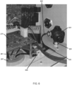
- FIG. 3 shows an angled side view of optical mount 155 and the associated fluid tubes 311a to 311e which are used to fill, empty, and to flush the sample container within the optical mount 155. Any suitable fluidic arrangement with any suitable filling and flushing process can be used. Fluid tubes 311a to 311e, which operate to perform the wet chemistry flow operations in the non-purged testing compartment 130 of the spectrophotometer 100, are electrically isolated from the electronic circuits of the electronics compartment 120 by light pipes 201a - 201d.
- electrically conductive components of the optical mount assembly 150 such as metallic optical mount 155, while electrically isolated from the voltages and electrical currents flowing in the electronics compartment 120, are typically electrically grounded to the chassis electrical ground, such as, for example, by metal brackets 261. Any suitable grounding connections, or grounding wires, typically electrically coupled to the metal chassis can be used.
- FIG. 4 is a drawing showing fluidic connections of the exemplary spectrophotometer 100 which bring a fluid to be tested into the optical mount 155.
- Connection 401 is fluidly coupled to a source of fluid to be tested, here configured to test a ballast water of a ship.
- Tube 411 couples the raw fluid sample to spectrophotometer 100 via a screen assembly 421 and a pressure regulator 431.
- the screened and pressure regulated fluid is coupled to the optical mount 155 via a motor-controlled valve assembly 450 and tubes 413 and 301e. Any suitable connections to the source of fluid to be tested can be used.
- any electrical aspects of the motor-controlled valve assembly 450 are fully contained within the purged electronics compartment 120, with only non-conductive, non-electrical fluid connections and components (of any suitable insulator, such as, for example, plastic or nylon) extending into the non-purged testing compartment 130.
- FIG. 5 is a drawing of the testing compartment 130 showing an exemplary pneumatic air connector 553 which couples pressurized air via nylon tube 561 to another pneumatic air connector 551 which couples the pressurized air into the purged electronics compartment 120.
- the air routing through the testing compartment 130 is a non-limiting exemplary air run of the exemplary spectrophotometer 100. Any suitable air connection can be made to, and through the cabinet of a spectrophotometer according to the Application. It is not necessary to route the pressurized air through the testing compartment 130. Also, any source of non-explosive air or gas (e.g. a dry nitrogen gas) could be used to purge the electronics compartment 120.
- a dry nitrogen gas could be used to purge the electronics compartment 120.
- This route is unimportant to the invention, however described as the exemplary instrument.
- FIG. 6 is a drawing showing internal pneumatic air connections in the electronics compartment 130.
- the pressurized air enters the electronics compartment 130 from the testing compartment 120 below via mechanical air coupler 551.
- the pressurized air flows into the purged electronics compartment 120 via pressure regulator 631.
- Pressure regulated air also flows through electrically controlled air valve 650 as part of an air purge process to clear processed sample fluid from the optical mount 155 between sample testing via pressurized air line 281.
- Pressure regulator 631 provides a termination point for tube 561.
- a 3/64" orifice in pressure regulator 631 provides the purge air into the chamber the electronics compartment 130.
- the outside pressurized air flows as input air to pressure regulator 631.
- One of the output ports of the pressure regulator 631 flows air through tube 681 to tube 281 via electrically controlled air valve 650, then down through the "firewall" as further detailed by FIG. 2A .
- Pressurized air also flows through tube 681 to air valve 650 and ultimately down to the drain solenoid used to purge the sample cell, cuvette 277.
- the drain solenoid (not shown) is programmatically controlled by a microcomputer in the electronics compartment.
- any suitable tube types can be used for pressurized air (e.g. pressurized air to purge the electronics compartment and to flush the sample cell) and for fluid transfer, including reagent flow, and sample fluid flow (e.g. ballast water).
- any suitable fittings or connectors can be used.
- the exact or exemplary tube routing is unimportant, such as, for example, it is not necessary to first route the source of pressurized air tube 561 via the testing compartment 130 as sourced by the exemplary NPT feedthough connector 553 at the bottom wall of the testing compartment 130. Such routing is merely exemplary and illustrative of the exemplary embodiment.
- a computer readable non-transitory storage medium as non-transitory data storage includes any data stored on any suitable media in a non-fleeting manner.
- Such data storage includes any suitable computer readable non-transitory storage medium, including, but not limited to hard drives, non-volatile RAM, SSD devices, CDs, DVDs, etc.
Landscapes
- Physics & Mathematics (AREA)
- Spectroscopy & Molecular Physics (AREA)
- General Physics & Mathematics (AREA)
- Chemical & Material Sciences (AREA)
- Health & Medical Sciences (AREA)
- Life Sciences & Earth Sciences (AREA)
- Pathology (AREA)
- General Health & Medical Sciences (AREA)
- Biochemistry (AREA)
- Immunology (AREA)
- Analytical Chemistry (AREA)
- Engineering & Computer Science (AREA)
- Medicinal Chemistry (AREA)
- Food Science & Technology (AREA)
- Mathematical Physics (AREA)
- Theoretical Computer Science (AREA)
- Chemical Kinetics & Catalysis (AREA)
- Plasma & Fusion (AREA)
- Investigating Or Analysing Materials By Optical Means (AREA)
- Investigating Or Analysing Materials By The Use Of Chemical Reactions (AREA)
- Optical Measuring Cells (AREA)
- Spectrometry And Color Measurement (AREA)
Description
- This application claims priority to and the benefit of co-pending
U.S. nonprovisional patent application Serial No. 16/139,555
SPECTROPHOTOMETER FOR USE IN EXPLOSIVE ATMOSPHERES, September 24, 2018. - The application relates to spectrophotometers, and particularly to spectrophotometers for use in explosive atmospheres.
- A spectrophotometer measures light transmission through a sample fluid at a particular wavelength of light. A reagent added to the fluid changes the color of the fluid, thus changing the transmission of light through the fluid based on the presence of a material to be detected. A colorimeter is a type of spectrophotometer operating a visible wavelength.
US6888636B2 describes an apparatus for inspection of fluids having a fluid analysis cell with a cavity therein enclosed by two light transmitting windows and having a spacer member fixedly positioned therebetween which provides a fluid analysis chamber of fixed pathlength where fluid flows by the windows and preferably wherein the flow laminar and at a uniform shear to provide accurate color measurements. Light transmitting and receiving probes are positioned adj acent to the viewing windows and wherein the faces of each probe are contiguous and flush with the viewing windows but are separated from the flow by the viewing windows, so that transmission measurements can be taken orthogonal to the direction of flow. The apparatus is particularly useful in the manufacture of dispersions and tints used in the manufacture of paints, so that the color of material being made can be accurately matched to a standard color in the wet state with confidence that the color will match in the dry state. - According to one aspect, the invention provides a photospectrometer according to claim 1.
- In another embodiment, at least one of the first light pipe or the second light pipe includes a push to connect (PTC) connector to mechanically coupled the at least one of the first light pipe or the second light pipe to the optical block.
- In yet another embodiment, the spectrophotometer further includes another light pipe to illuminate the fluid sample in the optical block with a back light for visual observation of a presence and color of the fluid sample.
- In yet another embodiment, the spectrophotometer further includes another light pipe to illuminate the fluid sample in the optical block with a calibration light to automatically determine a presence of fluid in the optical block.
- In yet another embodiment, the at least one light source includes a visible light.
- In yet another embodiment, the spectrophotometer includes a colorimeter, and wherein the at least one optical detector measures an amplitude of light at a particular color.
- In yet another embodiment, the at least one optical detector measures an amplitude of light at a particular color of light transmission through the fluid sample disposed in the optical block and wherein the fluid sample is combined with at least a first reagent.
- In yet another embodiment, the spectrophotometer measures a level of chlorine in a ship's ballast water.
- According to another aspect, a spectrophotometer for use in an explosive atmosphere includes a purged compartment which has disposed within, at least one light source, and at least one detector. A non-purged compartment has disposed within, an optical block having at least one fluid connection port. A first light pipe is optically coupled between the at least one light source and the optical block. A second light pipe is optically coupled between the optical block and the at least one detector. The non-purged compartment is adapted to perform spectrophotometry of a fluid sample disposed within a sample container in the optical block, and the purged compartment is electrically isolated from the non-purged compartment.
- According to the claimed invention, at least one of the first light pipe or the second light pipe include an acrylic plastic.
- In another embodiment, at least one of the first light pipe or the second light pipe include a PTC connector to mechanically coupled the at least one of the first light pipe or the second light pipe to the optical block.
- In yet another embodiment, the spectrophotometer further includes another light pipe to illuminate the fluid sample in the optical block with a back light for visual observation of a presence and color of the fluid sample.
- In yet another embodiment, the spectrophotometer further including another light pipe to illuminate the fluid sample in the optical block with a calibration light to automatically determine a presence of fluid in the optical block.
- In yet another embodiment, the at least one light source includes a visible light.
- In yet another embodiment, the spectrophotometer includes a colorimeter, and wherein the detector measures an amplitude of light at a particular color.
- In yet another embodiment, the detector measures an amplitude of light at a particular color of light transmission through the fluid sample disposed in the optical block and wherein the fluid sample is combined with at least a first reagent.
- In yet another embodiment, the spectrophotometer measures a level of chlorine in a ship's ballast water.
- According to yet another aspect, a method of measuring a presence or concentration of an organic or inorganic compound in a fluid in an explosive atmosphere includes: providing a spectrophotometer including: a purged compartment having disposed within: at least one light source, at least one detector, a non-purged compartment having disposed within: an optical block having at least one fluid connection port, a first light pipe optically coupled between the at least one light source and the optical block, and a second light pipe optically coupled between the optical block and the at least one detector; purging the purged compartment with a positive air pressure; filling a sample container with the fluid to be tested; injecting at least one reagent into the fluid; measuring an amount transmission of a light from the light source transmitted through the fluid and reagent via the first light pipe and the second light pipe to the detector; and determining the presence or concentration of the organic or inorganic compound in the fluid in the explosive atmosphere based on the amount transmission of the light.
- In one embodiment, the step of injecting, includes injecting at least one reagent for a detection of chlorine into the fluid, and the step of determining the presence or concentration includes determining the presence or concentration of chlorine in a ship's ballast water.
- In another embodiment, the step of injecting, includes injecting at least one reagent to determine the presence or concentration of a micro-organism into the fluid, and the step of determining the presence or concentration includes determining the presence or concentration of the micro-organism in the fluid.
- In yet another embodiment, the step of injecting, includes injecting at least one reagent for to determine the presence or concentration of a heavy metal into the fluid, and the step of determining the presence or concentration includes determining the presence or concentration of the heavy metal in the fluid.
- The foregoing and other aspects, features, and advantages of the application will become more apparent from the following description and from the claims.
- The features of the application can be better understood with reference to the drawings described below, and the claims. The drawings are not necessarily to scale, emphasis instead generally being placed upon illustrating the principles described herein. In the drawings, like numerals are used to indicate like parts throughout the various views.
-
FIG. 1 is a drawing of an exemplary spectrophotometer for use in explosive atmospheres according to the Application; -
FIG. 2A shows a drawing of an exemplary optical mount assembly and associated fluid, pneumatic, and flexible light pipe connections; -
FIG. 2B is a drawing showing a close up view of the optical mount ofFIG. 2A ; -
FIG. 3 is a drawing showing an angled side view of the optical mount with associated fluid connections; -
FIG. 4 is a drawing showing fluidic connections of the exemplary spectrophotometer ofFIG. 1 ; -
FIG. 5 is a drawing of thetesting compartment 130 showing an exemplary pneumatic air connection of the spectrophotometer ofFIG. 1 ; and -
FIG. 6 is a drawing showing internal pneumatic air connections in the electronics compartment of the spectrophotometer ofFIG. 1 . - Light pipe - The light pipe transmits light with a substantially minimal wavelength shift or wavelength distortion of the transmitted light. Light pipes for the spectrophotometer according to the invention are formed or cut from an acrylic plastic. As used herein, a light pipe is distinguished from, and does not include typical silica based glass fiber optic cables.
- As described hereinabove, a spectrophotometer measures light transmission at a particular wavelength of light through a sample of a fluid. A reagent added to the fluid changes the color of the fluid in response to the presence of certain materials (including certain organic or inorganic materials or substances) in the fluid, thus changing the transmission of light through the fluid based on the presence of a material to be detected. A colorimeter is a type of spectrophotometer operating a visible wavelength.
U.S. Patent No. 8,119,068 , FLUID CONTENT MONITOR, assigned to HF Scientific, the same assignee of this Application, describes an exemplary colorimeter as a fluid content monitor including a cuvette, a colorimeter adapted to generate a signal indicative of contents of a fluid sample contained in the cuvette, a container for holding a reagent, and a pump assembly for delivering reagent from the container to the cuvette. The '068 patent is incorporated herein in its entirety for all purposes. - Reagents are available, in development, or contemplated for the detection of a vast variety of organic and inorganic materials, including microorganisms, metals, alloys, and compounds. These reagents are typically injected into a fluid sample to determine a presence or concentration of the organic and inorganic material in the fluid.
- Such fluid testing is common in industrial environments, such as to test the water quality or for particular contaminants in water including waste water, runoff water (e.g. for pesticides), and ballast water (e.g. for chlorine levels in a ship's ballast water).
- While spectrophotometers, including colorimeters, are known in the prior art, there is a need for fluid testing in explosive environments, such as, for example in ship ballast tanks, grain production and storage, and mines, etc. To minimize the risk of explosion, fluid to be tested for a certain material content (typically water) must be first removed from the explosive environment before testing.
- There is a need for a spectrophotometer which is suitable for use directly in an explosive environment, such as for continuous and automatic monitoring of a fluid directly in the explosive environment.
- Another problem is that fluid measuring sensors experience undesired refraction of light transmitted through a fluid where coupled via typical silica based fiber optic cables from a light source to a fluid light transmission sample and to a corresponding detector to measure the transmitted light through the fluid sample. The measurement can be distorted by the light refraction of the fiber optic cables as well as other optical properties of typical silica based fiber optic cables which can cause a shift of wavelength or otherwise introduce a wavelength dependent distortion of the light transmitted for a light source through a fluid sample under test and then to a light detector.
- It was realized that a spectrophotometer using acrylic plastic light pipes pipes, solved the problems of wavelength distortion imparted by typical fiber optic cables (e.g. single mode and multimode glass fibers). Thus, a spectrophotometer was realized substantially without wavelength distortion that can have separate compartments for electronics components, such as the light source and light detector and for chemistry "wet testing" of a fluid sample under test. Moreover, such light pipes are typically less costly than corresponding lengths of terminated silica based fiber optic cables.
- Also, for use in the most dangerous of explosive environments, beyond the electrical isolation imparted by the light pipes, the electronics compartment of the spectrophotometer can be built as a purged compartment. For example, the electronics compartment can be pressurized at a positive air pressure to purge any explosive gas or air suspended particulate matter otherwise present in the explosive atmosphere. Also, with the electrical isolation and physical separation of the fluid sample, an optical mount to perform the wet chemistry (including injection of a reagent into a fluid sample under test) can be present in a non-purged compartment about adj acent to the purged electronics compartment.
-
FIG. 1 is a drawing of anexemplary spectrophotometer 100 for use in explosive atmospheres according to the Application. Theelectronics compartment 120 is purged of environmental air by a source of non-explosive pressurized gas. The pressurized gas is typically pressurized air, such as, for example from an air hose connection to an inhouse or shipboard pneumatic air source. Any suitable gas can also be used, such as, for example, any suitable inert gas. The wet chemistry is performed in thenon-purged testing compartment 130. While referred to as known in the art as the "wet" or "wet chemistry" side, thetesting compartment 130 is substantially dry, and the water or fluid to be tested is pumped into a test container in anoptical mount 155. In the exemplary embodiment ofFIG. 1 , the purgedelectronics compartment 120 is a second enclosure built into a larger outer industrial enclosure, the part of the outer overall enclosure not contained with the inner box of theelectronics compartment 120, being defined as thetesting compartment 130. As long as theelectronics compartment 120 can be purged of the air from the explosive environment, typically by a positive pressure from a non-explosive air source, it is unimportant how the two compartments are constructed. Where a source of non-explosive pressurized air is available, a cost effective and efficient system and method to pressurize theelectronics compartment 120 is by use of a positive pressure non-explosive air source which maintains a pressure within theelectronics compartment 120 over the pressure of the surrounding explosive environment, while allowing a slight outflow of the non-explosive pressurized air from theelectronics compartment 120 into the surrounding explosive environment. - Beyond removing potentially explosive environmental air from the electronics compartment, removing possible electrical ignition sources from the
testing compartment 130 further configures an instrument for permissible use in an explosive environment. Here, flexible light pipes are used to electrically isolate the testing compartment, while transmitting to and receiving light from the optical mount in the testing compartment. -
FIG. 2A shows a drawing of an exemplaryoptical mount assembly 150, and its associated fluid, pneumatic, and flexible light pipe connections. To practice the most basic concept of the new instrument of the Application, a light pipe, here aflexible light pipe 201a, transmits light from a light source in theelectronics compartment 120 to theoptical mount 155 to illuminate a fluid under test in a transparent or translucent test container in theoptical mount 155 in thetesting compartment 130. The backlight from back lightflexible light pipe 201a is mechanically and optically coupled into theoptical mount 155 attermination point 279,FIG. 2B . Anotherflexible light pipe 201d conveys light transmitted through the sample container (and thus, through the fluid under test) to an optical detector in theelectronics compartment 120. While the exemplary instrument uses a light transmission technique, those skilled in the art will understand that any suitable light return to the detectorflexible light pipe 201d, such as a reflection test technique, as compared to the exemplary transmission test technique could also be used. In the Exemplary embodiment ofFIG. 2A , light pipes are part no. IF 101H-0-17 having a 2.0mm diameter optical fiber (lightguide), available from Industrial Fiber Optics of Tempe, AZ. The optical core of the exemplary light pipes is a Super Eska™ with a polyethylene cable jacket. The exact type or circular, square, or rectangular cross section shape and dimensions of any suitable light pipe is unimportant, and any suitable light pipe can be used. - An optional backlight conveyed to the back of the transparent test container (e.g.
FIG. 2B , cuvette 277) in theoptical mount 155 by a flexiblelight pipe 201c. The optional backlight illuminates the fluid in the test container so that an observer can see the fluid and the approximate color of the fluid through one or more windows in thespectrophotometer 100 cabinet. - An optional level calibration light provides a light in a physical position on the
optical mount 155, such that electronics in the electronics compartment can determine when the fluid test container is full of a fluid under test. While such features can be controlled by hardwired logic, typically the processes of a spectrophotometer 100 (e.g. draining and filling the fluid testing container) are run by one or more microcomputers within the electronics compartment. - The similar looking
line 281 is a pneumatic airline used to purge the fluid container before a later sample for test is pumped into the testing container in theoptical mount 155. - Exemplary
structural brackets 261 are used to mechanically mount theoptical head 155 to thebulkhead 291 which defines the break between purgedelectronics compartment 120 and thenon-purged testing compartment 130. Any suitable mounting techniques can be used. Note thatfeedthrough 297 need not be completely air-tight, because the exemplary positivepressure electronics compartment 120 is not hermetically sealed, but rather allows for a relatively small constant outflow of the non-explosive pressurized air. - On the
electronics compartment 120 side, exemplaryoptical connectors 261 couple each of theflexible light pipes 201a - 201c to a light source (typically a light emitting diode (LED)) or to an optical detector (flexiblelight pipe 201d). On thetesting compartment 130 side, it was realized that relatively small threaded PTC style hose fittings 203 (e.g. as can be used for relatively small diameter nylon pneumatic airlines) could be adapted to mechanically couple the flexible light pipes to theoptical head 155. In the Exemplary embodiment ofFIG. 2A , PTC fittings part no. KQ2H01-32N including an integral release collar, available from the SMC Corp of Noblesville, IN were used. Any suitable fitting or connector can be used, such as, for example, any suitable PTC fitting or connector. - The electro-optical components such as LEDs and the detector are typically mounted, such as by soldering, to one or more printed circuit boards (PCB) in the electronics compartment, such as, for example,
PCB 275.Flexible light pipes 201a - 201d, as well aspneumatic airline 281 can run through thebulkhead 291 by use of any suitable transition, such as for example, aflexible firewall feedthrough 281.Feedthrough 281 need not be air tight, only airflow restricting so as to maintain the positive pressure in theelectronics compartment 120. -
FIG. 2B is a drawing showing a close up view of theoptical mount 155 and its associated connections. -
Fluid connectors FIG. 2A ) into the fluid under test in a fluid test container (e.g.FIG. 2B , cuvette 277) in theoptical mount 155. Swagelok™ type plastic fluid hose connectors are shown in theexemplary spectrophotometer 100 ofFIG. 1 ,FIG. 2A , andFIG. 2B .Plastic standoffs 246,FIG. 2B , allowsFluid connectors plastic standoff 246 which mechanically and fluidly couple to theoptical mount 155. In the exemplary embodiment ofFIG. 2B ,plastic standoffs 246, are secured to respective ports of theoptical mount 155 by a double end taperedlocking plate 267 affixed to theoptical mount 155 by aPhilips head screw 268. However, any suitable fluid couplings can be used to couple one or more reagent bags (or any suitable source of reagent) tooptical mount 155. - As seen in more detail in
FIG. 2B , PTCstyle hose fittings 203 includeinserts 204 and are supplied as such, as one piece. The light pipes (201a - 201d) each have an acrylic core which is covered in black rubber or plastic. It was realized that covered light pipe can be robustly mechanically coupled to the various respective ports of theoptical mount 155 by use of these PTC connectors otherwise intended for pneumatic or fluid tubes. - In the exemplary embodiment of
FIG. 2B , the testing container includes a glass cuvette which is visible through an opening in theoptical mount 155. Also, in the exemplary embodiment ofFIG. 2B , rubber gasket 276 (e.g. a rubber gasket) is present at both the top and bottom of thecuvette 277. The reticulated part above the cell in this exemplary embodiment is threaded and screws down on to the cuvette compressing the two gaskets to seal the cuvette to theoptical mount 155. Thecuvette 277 is merely exemplary. Any suitable testing container or sample cell can be used. -
FIG. 3 shows an angled side view ofoptical mount 155 and the associatedfluid tubes 311a to 311e which are used to fill, empty, and to flush the sample container within theoptical mount 155. Any suitable fluidic arrangement with any suitable filling and flushing process can be used.Fluid tubes 311a to 311e, which operate to perform the wet chemistry flow operations in thenon-purged testing compartment 130 of thespectrophotometer 100, are electrically isolated from the electronic circuits of theelectronics compartment 120 bylight pipes 201a - 201d. Note that in theexemplary spectrophotometer 100, electrically conductive components of theoptical mount assembly 150, such as metallicoptical mount 155, while electrically isolated from the voltages and electrical currents flowing in theelectronics compartment 120, are typically electrically grounded to the chassis electrical ground, such as, for example, bymetal brackets 261. Any suitable grounding connections, or grounding wires, typically electrically coupled to the metal chassis can be used. -
FIG. 4 is a drawing showing fluidic connections of theexemplary spectrophotometer 100 which bring a fluid to be tested into theoptical mount 155.Connection 401 is fluidly coupled to a source of fluid to be tested, here configured to test a ballast water of a ship.Tube 411 couples the raw fluid sample to spectrophotometer 100 via ascreen assembly 421 and apressure regulator 431. The screened and pressure regulated fluid is coupled to theoptical mount 155 via a motor-controlledvalve assembly 450 andtubes valve assembly 450 are fully contained within the purgedelectronics compartment 120, with only non-conductive, non-electrical fluid connections and components (of any suitable insulator, such as, for example, plastic or nylon) extending into thenon-purged testing compartment 130. -
FIG. 5 is a drawing of thetesting compartment 130 showing an exemplarypneumatic air connector 553 which couples pressurized air vianylon tube 561 to anotherpneumatic air connector 551 which couples the pressurized air into the purgedelectronics compartment 120. The air routing through thetesting compartment 130 is a non-limiting exemplary air run of theexemplary spectrophotometer 100. Any suitable air connection can be made to, and through the cabinet of a spectrophotometer according to the Application. It is not necessary to route the pressurized air through thetesting compartment 130. Also, any source of non-explosive air or gas (e.g. a dry nitrogen gas) could be used to purge theelectronics compartment 120. For a "pass through" pressurized, but not hermitic purged compartment, there is always an air or gas flow with constant air or gas flow to the environment, therefore use of an available non-explosive air may be more economical than flowing a dedicated gas, such as a dry nitrogen gas. - In
FIG. 5 , the pressurized or pneumatic air enters the cabinet atbulkhead connector 553, travels viatube 561 toconnector 551 at the "firewall" between thenon-purged testing compartment 130 and the purged electronics compartment 120 (FIG. 1 ). This route is unimportant to the invention, however described as the exemplary instrument. -
FIG. 6 is a drawing showing internal pneumatic air connections in theelectronics compartment 130. The pressurized air enters theelectronics compartment 130 from thetesting compartment 120 below viamechanical air coupler 551. The pressurized air flows into the purgedelectronics compartment 120 viapressure regulator 631. Pressure regulated air also flows through electrically controlledair valve 650 as part of an air purge process to clear processed sample fluid from theoptical mount 155 between sample testing viapressurized air line 281. -
Pressure regulator 631 provides a termination point fortube 561. A 3/64" orifice inpressure regulator 631 provides the purge air into the chamber theelectronics compartment 130. - In
FIG. 6 , the outside pressurized air flows as input air topressure regulator 631. One of the output ports of thepressure regulator 631 flows air throughtube 681 totube 281 via electrically controlledair valve 650, then down through the "firewall" as further detailed byFIG. 2A . Pressurized air also flows throughtube 681 toair valve 650 and ultimately down to the drain solenoid used to purge the sample cell,cuvette 277. The drain solenoid (not shown) is programmatically controlled by a microcomputer in the electronics compartment. - Throughout the spectrophotometer, any suitable tube types can be used for pressurized air (e.g. pressurized air to purge the electronics compartment and to flush the sample cell) and for fluid transfer, including reagent flow, and sample fluid flow (e.g. ballast water). Also, any suitable fittings or connectors can be used. The exact or exemplary tube routing is unimportant, such as, for example, it is not necessary to first route the source of
pressurized air tube 561 via thetesting compartment 130 as sourced by the exemplaryNPT feedthough connector 553 at the bottom wall of thetesting compartment 130. Such routing is merely exemplary and illustrative of the exemplary embodiment. - Any firmware or software code, such as for one or more microcomputers operating in the electronics compartment can be proved on a computer readable non-transitory storage medium. A computer readable non-transitory storage medium as non-transitory data storage includes any data stored on any suitable media in a non-fleeting manner. Such data storage includes any suitable computer readable non-transitory storage medium, including, but not limited to hard drives, non-volatile RAM, SSD devices, CDs, DVDs, etc.
- It will be appreciated that variants of the above-disclosed and other features and functions, or alternatives thereof, may be combined into many other different systems or applications. Various presently unforeseen or unanticipated alternatives, modifications, variations, or improvements therein may be subsequently made by those skilled in the art within the scope of the invention as defined by the following claims.
Claims (13)
- A spectrophotometer (100) for use in an explosive atmosphere comprising:a purged compartment (120) having disposed within:at least one light source; andat least one detector;a non-purged compartment (130) having disposed within:
an optical block (155) having at least one fluid connection port;a first flexible light pipe (201a, 201b, 201c, 201d) optically coupled between said at least one light source and said optical block (155);a second flexible light pipe (201a, 201b, 201c, 201d) optically coupled between said optical block and said at least one detector; andwherein said non-purged compartment (130) is adapted to performspectrophotometry of a fluid sample disposed within a sample container (277) in said optical block (155), and said purged compartment (120) is electrically isolated from said non-purged compartment (130); andwherein at least one of said first flexible light pipe (201a, 201b, 201c, 201d) and said second flexible light pipe (201a, 201b, 201c, 201d) comprises an acrylic plastic. - The spectrophotometer of claim 1, wherein each of said first flexible light pipe (201a, 201b, 201c, 201d) and said second flexible light pipe (201a, 201b, 201c, 201d) comprises acrylic plastic.
- The spectrophotometer of claim 1 or claim 2, wherein at least one of said first flexible light pipe (201a, 201b, 201c, 201d) or said second flexible light pipe (201a, 201b, 201c, 201d) comprise a push to connect, PTC, connector to mechanically coupled said at least one of said first flexible light pipe (201a, 201b, 201c, 201d) or said second flexible light pipe (201a, 201b, 201c, 201d) to said optical block (155).
- The spectrophotometer of any one of claims 1 to 3, further comprising an additional flexible light pipe extending from said purged compartment (120) to the non-purged compartment (130) to illuminate the fluid sample in said optical block (155) with a back light for visual observation of a presence and color of the fluid sample.
- The spectrophotometer of any one of the preceding claims, further comprising an additional flexible light pipe extending from said purged compartment (120) to the non-purged compartment (130) to illuminate the fluid sample in said optical block with a calibration light to automatically determine a presence of fluid in said optical block (155).
- The spectrophotometer of any one of the preceding claims, wherein said at least one light source comprises a visible light.
- The spectrophotometer of any one of the preceding claims, wherein said spectrophotometer (100) comprises a colorimeter, and wherein said detector measures an amplitude of light at a particular color.
- The spectrometer of any one of the preceding claims, wherein said fluid sample is combined with at least a first reagent.
- The spectrophotometer of claim 8, wherein said detector measures an amplitude of light at a particular color of light transmission through the fluid sample disposed in said optical block (155)..
- The spectrophotometer of any one of the preceding claims, wherein said spectrophotometer (100) measures a level of chlorine in a ship's ballast water.
- The spectrometer of any one of the preceding claims, wherein said first flexible light pipe (201a) is optically coupled substantially over an entire optical path between said at least one light source and said optical block (155).
- The spectrometer of any one of the preceding claims, wherein said purged compartment (120) comprises a pressure regulator (631) disposed therein in fluid communication with said optical block (155) via an electrically controlled air valve (650) to purge the fluid sample from said optical block (155).
- The spectrometer of any one of the preceding claims, including one or more fluid connectors (245a, 245b) in fluid communication with said sample container (277) in said optical block (155) for introduction of said at least a first reagent.
Applications Claiming Priority (2)
| Application Number | Priority Date | Filing Date | Title |
|---|---|---|---|
| US16/139,555 US10883925B2 (en) | 2018-09-24 | 2018-09-24 | Spectrophotometer for use in explosive atmospheres |
| PCT/US2019/051900 WO2020068549A1 (en) | 2018-09-24 | 2019-09-19 | Spectrophotometer for use in explosive atmospheres |
Publications (3)
| Publication Number | Publication Date |
|---|---|
| EP3857206A1 EP3857206A1 (en) | 2021-08-04 |
| EP3857206A4 EP3857206A4 (en) | 2022-06-15 |
| EP3857206B1 true EP3857206B1 (en) | 2024-11-06 |
Family
ID=69883124
Family Applications (1)
| Application Number | Title | Priority Date | Filing Date |
|---|---|---|---|
| EP19868092.8A Active EP3857206B1 (en) | 2018-09-24 | 2019-09-19 | Spectrophotometer for use in explosive atmospheres |
Country Status (8)
| Country | Link |
|---|---|
| US (1) | US10883925B2 (en) |
| EP (1) | EP3857206B1 (en) |
| JP (1) | JP7030245B2 (en) |
| KR (1) | KR102501536B1 (en) |
| CN (1) | CN112752968B (en) |
| ES (1) | ES2996983T3 (en) |
| FI (1) | FI3857206T3 (en) |
| WO (1) | WO2020068549A1 (en) |
Family Cites Families (25)
| Publication number | Priority date | Publication date | Assignee | Title |
|---|---|---|---|---|
| US4123172A (en) * | 1976-09-07 | 1978-10-31 | Sterndent Corporation | Comparison type colorimeter |
| US4858768A (en) | 1986-08-04 | 1989-08-22 | The Coca-Cola Company | Method for discrimination between contaminated and uncontaminated containers |
| JPH01152343A (en) * | 1987-12-10 | 1989-06-14 | Asahi Glass Co Ltd | Photosensor |
| US5083865A (en) | 1990-05-11 | 1992-01-28 | Applied Materials, Inc. | Particle monitor system and method |
| US5880850A (en) | 1996-04-18 | 1999-03-09 | American Air Liquide Inc | Method and system for sensitive detection of molecular species in a vacuum by harmonic detection spectroscopy |
| JP2001281165A (en) * | 2000-03-31 | 2001-10-10 | Kokusai Gijutsu Kaihatsu Co Ltd | Substrate inspection method and apparatus |
| US6888636B2 (en) * | 2001-03-19 | 2005-05-03 | E. I. Du Pont De Nemours And Company | Method and apparatus for measuring the color properties of fluids |
| US20020187558A1 (en) | 2001-06-05 | 2002-12-12 | Advanced Exploration & Research, Inc. | Method for determining the amount of metal in water and kit therefor |
| AR037242A1 (en) * | 2002-10-08 | 2004-11-03 | Col Ven Sa | ROTARY TIRE COUPLING FOR AUTOMOTIVE VEHICLE WHEEL, TIRE INFLATION PRESSURE CONTROL PROVISION OF A COUPLING OR TOWING OF THE AUTOMOTIVE VEHICLE, PROCEDURE FOR PROVIDING AN AIR CONDUCTING INSIDE OF A FEMALE ROLLING METHOD |
| US7283245B2 (en) * | 2004-01-20 | 2007-10-16 | General Electric Company | Handheld device with a disposable element for chemical analysis of multiple analytes |
| CA2608429A1 (en) * | 2005-05-11 | 2006-11-23 | Anthony Albino | Reduced risk tobacco products and methods of making same |
| US7794660B2 (en) | 2006-01-13 | 2010-09-14 | Hf Scientific, Inc. | Fluid content monitor |
| US20120059254A1 (en) * | 2007-03-14 | 2012-03-08 | Wang Lifan | Apparatus and method for phase-space reduction for imaging of fluorescing, scattering and/or absorbing structures |
| WO2009094761A1 (en) | 2008-01-31 | 2009-08-06 | Exceltion Medical Innovations Inc. | Apparatus and method for urinalysis |
| US9772261B2 (en) | 2010-02-12 | 2017-09-26 | Fluidion Sas | Passive micro-vessel and sensor |
| EP3460458B1 (en) | 2010-02-19 | 2021-08-11 | Pacific Biosciences of California, Inc. | A method for nucleic acid sequencing |
| WO2015017415A2 (en) * | 2013-07-29 | 2015-02-05 | Rf Advanced Technology Group, Llc | Electrochemical and thermal digestion of organic molecules |
| US20120103823A1 (en) | 2010-10-08 | 2012-05-03 | Dweik Badawi M | Method for detecting individual oxidant species and halide anions in a sample using differential pulse non-stripping voltammetry |
| CN203203714U (en) * | 2012-11-23 | 2013-09-18 | 中国科学院上海光学精密机械研究所 | Absolute wavelength calibration instrument |
| KR101649968B1 (en) * | 2014-02-26 | 2016-08-22 | 남병현 | a residual chlorine detector and the multi-funtional residual chlorine detecting system using thereof |
| EP3719481B1 (en) * | 2015-02-06 | 2023-03-29 | Life Technologies Corporation | An optical instrument for biological analysis |
| US9482833B1 (en) * | 2015-09-24 | 2016-11-01 | International Business Machines Corporation | Light pipe connector apparatus |
| CA3220899A1 (en) * | 2016-02-04 | 2017-08-10 | Nova Biomedical Corporation | Analyte system and method for determining hemoglobin parameters in whole blood |
| CN109073455A (en) | 2016-03-07 | 2018-12-21 | Ysi公司 | Optical nitrate sensor for multiparameter water quality measurement |
| DE102017114317A1 (en) * | 2016-07-27 | 2018-02-01 | Endress+Hauser Conducta Gmbh+Co. Kg | Spectrometric measuring device |
-
2018
- 2018-09-24 US US16/139,555 patent/US10883925B2/en active Active
-
2019
- 2019-09-19 EP EP19868092.8A patent/EP3857206B1/en active Active
- 2019-09-19 FI FIEP19868092.8T patent/FI3857206T3/en active
- 2019-09-19 WO PCT/US2019/051900 patent/WO2020068549A1/en not_active Ceased
- 2019-09-19 CN CN201980062416.7A patent/CN112752968B/en active Active
- 2019-09-19 ES ES19868092T patent/ES2996983T3/en active Active
- 2019-09-19 KR KR1020217012406A patent/KR102501536B1/en active Active
- 2019-09-19 JP JP2021525287A patent/JP7030245B2/en active Active
Also Published As
| Publication number | Publication date |
|---|---|
| EP3857206A1 (en) | 2021-08-04 |
| FI3857206T3 (en) | 2025-01-29 |
| JP2021530719A (en) | 2021-11-11 |
| JP7030245B2 (en) | 2022-03-04 |
| WO2020068549A1 (en) | 2020-04-02 |
| KR102501536B1 (en) | 2023-02-17 |
| CN112752968A (en) | 2021-05-04 |
| EP3857206A4 (en) | 2022-06-15 |
| KR20210062685A (en) | 2021-05-31 |
| US10883925B2 (en) | 2021-01-05 |
| US20200096440A1 (en) | 2020-03-26 |
| CN112752968B (en) | 2024-02-27 |
| ES2996983T3 (en) | 2025-02-13 |
Similar Documents
| Publication | Publication Date | Title |
|---|---|---|
| JP5902751B2 (en) | Ultrasonic liquid height detector | |
| EP1370849B1 (en) | Method and apparatus for measuring properties of fluids | |
| US11174036B2 (en) | Methods for installation of sensors and determining a fuel level measurement of fuel using a fuel level measurement system | |
| US20080098809A1 (en) | Electronic level gage assembly | |
| US20110157351A1 (en) | Apparatus and Method for Analyzing Fluids in Vessels and Pipelines | |
| CN112179406A (en) | In-line measuring device | |
| US5936715A (en) | On-line method and apparatus for determining the condition of circulating fluids | |
| US10883925B2 (en) | Spectrophotometer for use in explosive atmospheres | |
| IT9019721A1 (en) | EQUIPMENT FOR THE DETECTION OF INFRARED LASER GAS AND OPTICAL FIBERS | |
| JP6702995B2 (en) | Ultrasonic liquid level sensing system | |
| US20220244128A1 (en) | Liquid Leakage Detector and Method to Detect Liquid Leaking | |
| US20240060873A1 (en) | Optical analysis device for determining a characteristic of a medium, housing, and system | |
| EP3465103B1 (en) | Flow meter cartridge, flow meter comprising the flow meter cartridge, method of using the flow meter | |
| US11747200B2 (en) | Optical process sensor, measuring head, measuring system comprising the two and method for calibration and/or validation | |
| US7259848B2 (en) | Process measuring point | |
| US20030019650A1 (en) | Process adapter | |
| RU115925U1 (en) | DEVICE FOR MEASURING AND CONTROL OF DIELECTRIC PERMEABILITY OF DIELECTRIC MEDIA | |
| EP2803955B1 (en) | Ultrasonic liquid level sensing systems |
Legal Events
| Date | Code | Title | Description |
|---|---|---|---|
| STAA | Information on the status of an ep patent application or granted ep patent |
Free format text: STATUS: THE INTERNATIONAL PUBLICATION HAS BEEN MADE |
|
| PUAI | Public reference made under article 153(3) epc to a published international application that has entered the european phase |
Free format text: ORIGINAL CODE: 0009012 |
|
| STAA | Information on the status of an ep patent application or granted ep patent |
Free format text: STATUS: REQUEST FOR EXAMINATION WAS MADE |
|
| 17P | Request for examination filed |
Effective date: 20210326 |
|
| AK | Designated contracting states |
Kind code of ref document: A1 Designated state(s): AL AT BE BG CH CY CZ DE DK EE ES FI FR GB GR HR HU IE IS IT LI LT LU LV MC MK MT NL NO PL PT RO RS SE SI SK SM TR |
|
| DAV | Request for validation of the european patent (deleted) | ||
| DAX | Request for extension of the european patent (deleted) | ||
| A4 | Supplementary search report drawn up and despatched |
Effective date: 20220518 |
|
| RIC1 | Information provided on ipc code assigned before grant |
Ipc: G01J 3/02 20060101ALI20220512BHEP Ipc: A61B 5/103 20060101ALI20220512BHEP Ipc: G01N 21/31 20060101AFI20220512BHEP |
|
| GRAP | Despatch of communication of intention to grant a patent |
Free format text: ORIGINAL CODE: EPIDOSNIGR1 |
|
| STAA | Information on the status of an ep patent application or granted ep patent |
Free format text: STATUS: GRANT OF PATENT IS INTENDED |
|
| RIC1 | Information provided on ipc code assigned before grant |
Ipc: G01N 21/77 20060101ALI20240502BHEP Ipc: G01N 33/18 20060101ALI20240502BHEP Ipc: G01N 21/78 20060101ALI20240502BHEP Ipc: G01N 21/25 20060101ALI20240502BHEP Ipc: G01J 3/02 20060101ALI20240502BHEP Ipc: A61B 5/103 20060101ALI20240502BHEP Ipc: G01N 21/31 20060101AFI20240502BHEP |
|
| INTG | Intention to grant announced |
Effective date: 20240516 |
|
| GRAS | Grant fee paid |
Free format text: ORIGINAL CODE: EPIDOSNIGR3 |
|
| GRAA | (expected) grant |
Free format text: ORIGINAL CODE: 0009210 |
|
| STAA | Information on the status of an ep patent application or granted ep patent |
Free format text: STATUS: THE PATENT HAS BEEN GRANTED |
|
| P01 | Opt-out of the competence of the unified patent court (upc) registered |
Free format text: CASE NUMBER: APP_51583/2024 Effective date: 20240912 |
|
| AK | Designated contracting states |
Kind code of ref document: B1 Designated state(s): AL AT BE BG CH CY CZ DE DK EE ES FI FR GB GR HR HU IE IS IT LI LT LU LV MC MK MT NL NO PL PT RO RS SE SI SK SM TR |
|
| REG | Reference to a national code |
Ref country code: GB Ref legal event code: FG4D |
|
| REG | Reference to a national code |
Ref country code: CH Ref legal event code: EP |
|
| REG | Reference to a national code |
Ref country code: DE Ref legal event code: R096 Ref document number: 602019061705 Country of ref document: DE |
|
| REG | Reference to a national code |
Ref country code: IE Ref legal event code: FG4D |
|
| REG | Reference to a national code |
Ref country code: SE Ref legal event code: TRGR |
|
| REG | Reference to a national code |
Ref country code: FI Ref legal event code: FGE |
|
| REG | Reference to a national code |
Ref country code: ES Ref legal event code: FG2A Ref document number: 2996983 Country of ref document: ES Kind code of ref document: T3 Effective date: 20250213 |
|
| REG | Reference to a national code |
Ref country code: LT Ref legal event code: MG9D |
|
| REG | Reference to a national code |
Ref country code: NL Ref legal event code: MP Effective date: 20241106 |
|
| PG25 | Lapsed in a contracting state [announced via postgrant information from national office to epo] |
Ref country code: PT Free format text: LAPSE BECAUSE OF FAILURE TO SUBMIT A TRANSLATION OF THE DESCRIPTION OR TO PAY THE FEE WITHIN THE PRESCRIBED TIME-LIMIT Effective date: 20250306 Ref country code: IS Free format text: LAPSE BECAUSE OF FAILURE TO SUBMIT A TRANSLATION OF THE DESCRIPTION OR TO PAY THE FEE WITHIN THE PRESCRIBED TIME-LIMIT Effective date: 20250306 Ref country code: HR Free format text: LAPSE BECAUSE OF FAILURE TO SUBMIT A TRANSLATION OF THE DESCRIPTION OR TO PAY THE FEE WITHIN THE PRESCRIBED TIME-LIMIT Effective date: 20241106 |
|
| PG25 | Lapsed in a contracting state [announced via postgrant information from national office to epo] |
Ref country code: NL Free format text: LAPSE BECAUSE OF FAILURE TO SUBMIT A TRANSLATION OF THE DESCRIPTION OR TO PAY THE FEE WITHIN THE PRESCRIBED TIME-LIMIT Effective date: 20241106 |
|
| REG | Reference to a national code |
Ref country code: AT Ref legal event code: MK05 Ref document number: 1739846 Country of ref document: AT Kind code of ref document: T Effective date: 20241106 |
|
| PG25 | Lapsed in a contracting state [announced via postgrant information from national office to epo] |
Ref country code: BG Free format text: LAPSE BECAUSE OF FAILURE TO SUBMIT A TRANSLATION OF THE DESCRIPTION OR TO PAY THE FEE WITHIN THE PRESCRIBED TIME-LIMIT Effective date: 20241106 |
|
| PG25 | Lapsed in a contracting state [announced via postgrant information from national office to epo] |
Ref country code: NO Free format text: LAPSE BECAUSE OF FAILURE TO SUBMIT A TRANSLATION OF THE DESCRIPTION OR TO PAY THE FEE WITHIN THE PRESCRIBED TIME-LIMIT Effective date: 20250206 |
|
| PG25 | Lapsed in a contracting state [announced via postgrant information from national office to epo] |
Ref country code: AT Free format text: LAPSE BECAUSE OF FAILURE TO SUBMIT A TRANSLATION OF THE DESCRIPTION OR TO PAY THE FEE WITHIN THE PRESCRIBED TIME-LIMIT Effective date: 20241106 Ref country code: LV Free format text: LAPSE BECAUSE OF FAILURE TO SUBMIT A TRANSLATION OF THE DESCRIPTION OR TO PAY THE FEE WITHIN THE PRESCRIBED TIME-LIMIT Effective date: 20241106 Ref country code: GR Free format text: LAPSE BECAUSE OF FAILURE TO SUBMIT A TRANSLATION OF THE DESCRIPTION OR TO PAY THE FEE WITHIN THE PRESCRIBED TIME-LIMIT Effective date: 20250207 |
|
| PG25 | Lapsed in a contracting state [announced via postgrant information from national office to epo] |
Ref country code: PL Free format text: LAPSE BECAUSE OF FAILURE TO SUBMIT A TRANSLATION OF THE DESCRIPTION OR TO PAY THE FEE WITHIN THE PRESCRIBED TIME-LIMIT Effective date: 20241106 |
|
| PG25 | Lapsed in a contracting state [announced via postgrant information from national office to epo] |
Ref country code: RS Free format text: LAPSE BECAUSE OF FAILURE TO SUBMIT A TRANSLATION OF THE DESCRIPTION OR TO PAY THE FEE WITHIN THE PRESCRIBED TIME-LIMIT Effective date: 20250206 |
|
| PG25 | Lapsed in a contracting state [announced via postgrant information from national office to epo] |
Ref country code: SM Free format text: LAPSE BECAUSE OF FAILURE TO SUBMIT A TRANSLATION OF THE DESCRIPTION OR TO PAY THE FEE WITHIN THE PRESCRIBED TIME-LIMIT Effective date: 20241106 |
|
| PG25 | Lapsed in a contracting state [announced via postgrant information from national office to epo] |
Ref country code: DK Free format text: LAPSE BECAUSE OF FAILURE TO SUBMIT A TRANSLATION OF THE DESCRIPTION OR TO PAY THE FEE WITHIN THE PRESCRIBED TIME-LIMIT Effective date: 20241106 |
|
| PG25 | Lapsed in a contracting state [announced via postgrant information from national office to epo] |
Ref country code: EE Free format text: LAPSE BECAUSE OF FAILURE TO SUBMIT A TRANSLATION OF THE DESCRIPTION OR TO PAY THE FEE WITHIN THE PRESCRIBED TIME-LIMIT Effective date: 20241106 |
|
| PG25 | Lapsed in a contracting state [announced via postgrant information from national office to epo] |
Ref country code: RO Free format text: LAPSE BECAUSE OF FAILURE TO SUBMIT A TRANSLATION OF THE DESCRIPTION OR TO PAY THE FEE WITHIN THE PRESCRIBED TIME-LIMIT Effective date: 20241106 |
|
| PG25 | Lapsed in a contracting state [announced via postgrant information from national office to epo] |
Ref country code: SK Free format text: LAPSE BECAUSE OF FAILURE TO SUBMIT A TRANSLATION OF THE DESCRIPTION OR TO PAY THE FEE WITHIN THE PRESCRIBED TIME-LIMIT Effective date: 20241106 |
|
| PG25 | Lapsed in a contracting state [announced via postgrant information from national office to epo] |
Ref country code: CZ Free format text: LAPSE BECAUSE OF FAILURE TO SUBMIT A TRANSLATION OF THE DESCRIPTION OR TO PAY THE FEE WITHIN THE PRESCRIBED TIME-LIMIT Effective date: 20241106 |
|
| PG25 | Lapsed in a contracting state [announced via postgrant information from national office to epo] |
Ref country code: IT Free format text: LAPSE BECAUSE OF FAILURE TO SUBMIT A TRANSLATION OF THE DESCRIPTION OR TO PAY THE FEE WITHIN THE PRESCRIBED TIME-LIMIT Effective date: 20241106 |
|
| REG | Reference to a national code |
Ref country code: DE Ref legal event code: R097 Ref document number: 602019061705 Country of ref document: DE |
|
| PLBE | No opposition filed within time limit |
Free format text: ORIGINAL CODE: 0009261 |
|
| STAA | Information on the status of an ep patent application or granted ep patent |
Free format text: STATUS: NO OPPOSITION FILED WITHIN TIME LIMIT |
|
| PGFP | Annual fee paid to national office [announced via postgrant information from national office to epo] |
Ref country code: FI Payment date: 20250925 Year of fee payment: 7 |
|
| PGFP | Annual fee paid to national office [announced via postgrant information from national office to epo] |
Ref country code: DE Payment date: 20250929 Year of fee payment: 7 |
|
| 26N | No opposition filed |
Effective date: 20250807 |
|
| PGFP | Annual fee paid to national office [announced via postgrant information from national office to epo] |
Ref country code: GB Payment date: 20250929 Year of fee payment: 7 |
|
| PGFP | Annual fee paid to national office [announced via postgrant information from national office to epo] |
Ref country code: SE Payment date: 20250927 Year of fee payment: 7 |
|
| PGFP | Annual fee paid to national office [announced via postgrant information from national office to epo] |
Ref country code: ES Payment date: 20251001 Year of fee payment: 7 |
|
| REG | Reference to a national code |
Ref country code: CH Ref legal event code: H13 Free format text: ST27 STATUS EVENT CODE: U-0-0-H10-H13 (AS PROVIDED BY THE NATIONAL OFFICE) Effective date: 20260504 |