EP3857119B1 - Projection headlight for a vehicle and vehicle - Google Patents
Projection headlight for a vehicle and vehicle Download PDFInfo
- Publication number
- EP3857119B1 EP3857119B1 EP18782344.8A EP18782344A EP3857119B1 EP 3857119 B1 EP3857119 B1 EP 3857119B1 EP 18782344 A EP18782344 A EP 18782344A EP 3857119 B1 EP3857119 B1 EP 3857119B1
- Authority
- EP
- European Patent Office
- Prior art keywords
- projection
- vehicle
- projection headlight
- light source
- headlight
- Prior art date
- Legal status (The legal status is an assumption and is not a legal conclusion. Google has not performed a legal analysis and makes no representation as to the accuracy of the status listed.)
- Active
Links
Images


Classifications
-
- F—MECHANICAL ENGINEERING; LIGHTING; HEATING; WEAPONS; BLASTING
- F21—LIGHTING
- F21S—NON-PORTABLE LIGHTING DEVICES; SYSTEMS THEREOF; VEHICLE LIGHTING DEVICES SPECIALLY ADAPTED FOR VEHICLE EXTERIORS
- F21S41/00—Illuminating devices specially adapted for vehicle exteriors, e.g. headlamps
- F21S41/10—Illuminating devices specially adapted for vehicle exteriors, e.g. headlamps characterised by the light source
- F21S41/14—Illuminating devices specially adapted for vehicle exteriors, e.g. headlamps characterised by the light source characterised by the type of light source
- F21S41/141—Light emitting diodes [LED]
- F21S41/143—Light emitting diodes [LED] the main emission direction of the LED being parallel to the optical axis of the illuminating device
-
- F—MECHANICAL ENGINEERING; LIGHTING; HEATING; WEAPONS; BLASTING
- F21—LIGHTING
- F21S—NON-PORTABLE LIGHTING DEVICES; SYSTEMS THEREOF; VEHICLE LIGHTING DEVICES SPECIALLY ADAPTED FOR VEHICLE EXTERIORS
- F21S41/00—Illuminating devices specially adapted for vehicle exteriors, e.g. headlamps
- F21S41/10—Illuminating devices specially adapted for vehicle exteriors, e.g. headlamps characterised by the light source
- F21S41/14—Illuminating devices specially adapted for vehicle exteriors, e.g. headlamps characterised by the light source characterised by the type of light source
- F21S41/141—Light emitting diodes [LED]
- F21S41/151—Light emitting diodes [LED] arranged in one or more lines
-
- F—MECHANICAL ENGINEERING; LIGHTING; HEATING; WEAPONS; BLASTING
- F21—LIGHTING
- F21S—NON-PORTABLE LIGHTING DEVICES; SYSTEMS THEREOF; VEHICLE LIGHTING DEVICES SPECIALLY ADAPTED FOR VEHICLE EXTERIORS
- F21S41/00—Illuminating devices specially adapted for vehicle exteriors, e.g. headlamps
- F21S41/20—Illuminating devices specially adapted for vehicle exteriors, e.g. headlamps characterised by refractors, transparent cover plates, light guides or filters
- F21S41/25—Projection lenses
-
- F—MECHANICAL ENGINEERING; LIGHTING; HEATING; WEAPONS; BLASTING
- F21—LIGHTING
- F21S—NON-PORTABLE LIGHTING DEVICES; SYSTEMS THEREOF; VEHICLE LIGHTING DEVICES SPECIALLY ADAPTED FOR VEHICLE EXTERIORS
- F21S41/00—Illuminating devices specially adapted for vehicle exteriors, e.g. headlamps
- F21S41/20—Illuminating devices specially adapted for vehicle exteriors, e.g. headlamps characterised by refractors, transparent cover plates, light guides or filters
- F21S41/25—Projection lenses
- F21S41/265—Composite lenses; Lenses with a patch-like shape
-
- F—MECHANICAL ENGINEERING; LIGHTING; HEATING; WEAPONS; BLASTING
- F21—LIGHTING
- F21S—NON-PORTABLE LIGHTING DEVICES; SYSTEMS THEREOF; VEHICLE LIGHTING DEVICES SPECIALLY ADAPTED FOR VEHICLE EXTERIORS
- F21S41/00—Illuminating devices specially adapted for vehicle exteriors, e.g. headlamps
- F21S41/20—Illuminating devices specially adapted for vehicle exteriors, e.g. headlamps characterised by refractors, transparent cover plates, light guides or filters
- F21S41/25—Projection lenses
- F21S41/275—Lens surfaces, e.g. coatings or surface structures
-
- F—MECHANICAL ENGINEERING; LIGHTING; HEATING; WEAPONS; BLASTING
- F21—LIGHTING
- F21S—NON-PORTABLE LIGHTING DEVICES; SYSTEMS THEREOF; VEHICLE LIGHTING DEVICES SPECIALLY ADAPTED FOR VEHICLE EXTERIORS
- F21S41/00—Illuminating devices specially adapted for vehicle exteriors, e.g. headlamps
- F21S41/20—Illuminating devices specially adapted for vehicle exteriors, e.g. headlamps characterised by refractors, transparent cover plates, light guides or filters
- F21S41/285—Refractors, transparent cover plates, light guides or filters not provided in groups F21S41/24 - F21S41/2805
-
- F—MECHANICAL ENGINEERING; LIGHTING; HEATING; WEAPONS; BLASTING
- F21—LIGHTING
- F21S—NON-PORTABLE LIGHTING DEVICES; SYSTEMS THEREOF; VEHICLE LIGHTING DEVICES SPECIALLY ADAPTED FOR VEHICLE EXTERIORS
- F21S41/00—Illuminating devices specially adapted for vehicle exteriors, e.g. headlamps
- F21S41/40—Illuminating devices specially adapted for vehicle exteriors, e.g. headlamps characterised by screens, non-reflecting members, light-shielding members or fixed shades
- F21S41/43—Illuminating devices specially adapted for vehicle exteriors, e.g. headlamps characterised by screens, non-reflecting members, light-shielding members or fixed shades characterised by the shape thereof
-
- F—MECHANICAL ENGINEERING; LIGHTING; HEATING; WEAPONS; BLASTING
- F21—LIGHTING
- F21S—NON-PORTABLE LIGHTING DEVICES; SYSTEMS THEREOF; VEHICLE LIGHTING DEVICES SPECIALLY ADAPTED FOR VEHICLE EXTERIORS
- F21S45/00—Arrangements within vehicle lighting devices specially adapted for vehicle exteriors, for purposes other than emission or distribution of light
- F21S45/40—Cooling of lighting devices
- F21S45/47—Passive cooling, e.g. using fins, thermal conductive elements or openings
-
- B—PERFORMING OPERATIONS; TRANSPORTING
- B60—VEHICLES IN GENERAL
- B60Q—ARRANGEMENT OF SIGNALLING OR LIGHTING DEVICES, THE MOUNTING OR SUPPORTING THEREOF OR CIRCUITS THEREFOR, FOR VEHICLES IN GENERAL
- B60Q2400/00—Special features or arrangements of exterior signal lamps for vehicles
- B60Q2400/50—Projected symbol or information, e.g. onto the road or car body
-
- F—MECHANICAL ENGINEERING; LIGHTING; HEATING; WEAPONS; BLASTING
- F21—LIGHTING
- F21W—INDEXING SCHEME ASSOCIATED WITH SUBCLASSES F21K, F21L, F21S and F21V, RELATING TO USES OR APPLICATIONS OF LIGHTING DEVICES OR SYSTEMS
- F21W2103/00—Exterior vehicle lighting devices for signalling purposes
- F21W2103/60—Projection of signs from lighting devices, e.g. symbols or information being projected onto the road
Definitions
- the invention is related to a projection headlight for a vehicle, comprising at least one light source, a projection lens, a condenser lens arranged between the at least one light source and the projection lens, the condenser lens having a flat side and a curved side, and comprising at least one printed graphic arranged between the condenser lens and the projection lens. Furthermore, the invention is related to a vehicle having at least one projection headlight.
- a projection headlight in a motor vehicle a warning symbol can be projected onto the roadway in the principle of a slide projector.
- a graphic printed on a (plastic) slide is imaged using a projection lens.
- a condenser lens is inserted between the light source and the slide.
- the slide is arranged between the condenser lens and the projection lens as an independent component.
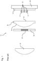
- Such a projection headlight is shown in Figs. 1 and 2 .
- the projection headlight (10) comprises at least one light source (20), a projection lens (40), a condenser lens (30) arranged between the at least one light source (20) and the projection lens (40).
- the condenser lens (30) is having a flat side (32) and a curved side (34).
- the projection headlight (10) further comprises a slide (60) with a printed graphic (50).
- the slide (60) is arranged between the condenser lens (30) and the projection lens (40).
- the slide (60) is spaced to the condenser lens (30) with a certain distance.
- DE 10 2004 058 153 A1 discloses to a lighting device for vehicles with a housing, the front opening of which is covered by a lens. At least one section of the lens has a smooth inside and outside. A light element and a component, which is provided with an identification mark are arranged in the interior of the housing. The identification mark is visible through a section of the light disk that has a smooth outside and inside.
- DE 10 2014 203 313 A1 shows a lighting device for a motor vehicle with at least one light source, the light emission of which provides a light function for the motor vehicle, and with at least one reflector, the lighting device is designed in such a way that a roadway is illuminated or can be illuminated with a light pattern. At least one illuminant for generating the light pattern is arranged behind the at least one reflector in the light exit direction.
- DE 10 2017 104 488 A1 discloses a warning device for an industrial truck, which, arranged on the industrial truck, projects a pictorial information symbol, in particular a pictorial warning symbol, onto a roadway.
- the warning device being designed as a projector which emits a light source that emits a luminous flux, and an image template of the information symbol to be projected, which can be transilluminated by the luminous flux generated by the light source.
- the original image has at least one area which is transparent to the luminous flux of the light source and an area that shades the luminous flux of the light source
- the projector has a free-form lens arranged between the light source and the original image, the free-form lens being designed in such a way that the luminous flux of the light source is incident on the translucent area of the original image is bundled.
- US 2017/0210282 A1 discloses a multifunction assembly comprised of: an outer surface structure containing a side door that supports at least one exterior mirror assembly, an exterior door handle assembly of said door, and an exterior laser emitter which emits a fixed and direct line of laser light downwards on said ground adjacent to the vehicle, indicating an area where the doors open and combines functions associated with other indicator signal devices, sensors and open door commands, and an ultraviolet light emitter device.
- WO 2014/045168 A1 discloses an optical device comprising a first surface with a plurality of micro sized facets, each facet having a respective orientation. Said plurality of facets having an optical axis, which extends parallel to the normal vector to an average orientation of all said respective orientations.
- the plurality of facets comprising at least a first and a second group of facets, each group is formed by a respective number of at least twenty-five compactly arranged neighboring facets.
- Each group is arranged to generate during operation a respective, mutually identical whole pattern.
- Each facet in a respective group is arranged to display a sub-pattern of said respective whole pattern. The whole patterns are mutually superpositioned.
- the object of the present invention is to provide a projection headlight for a vehicle, in particular for a motor vehicle, which at least partially avoids the previously described disadvantages.
- Aforesaid problem is solved by a projection headlight with the features of claim 1 and by a vehicle with the features of claim 8.
- a projection headlight for a vehicle comprising at least one light source, a projection lens, a condenser lens arranged between the at least one light source and the projection lens.
- the condenser lens is having a flat side and a curved side.
- the projection headlight further comprises at least one printed graphic arranged between the condenser lens and the projection lens. The at least one printed graphic is printed on the flat side of the condenser lens.
- the graphic to be imaged onto the roadway is printed directly on the flat surface of the condenser lens.
- the printing can be done in digital printing, screen printing or in particular in pad printing.
- the graphic can also be a coating, for example a colored coating with pigments or dyes and interference coatings, into which the graphic to be generated is introduced by ablation processes, for example removal by means of laser. No additional slide is needed. This saves costs.
- the projection headlight is more efficient due to lower light losses, since the elimination of the slide eliminates two interfaces at the transition between air and (plastic) slide.
- the size of the projection headlight can be reduced by the omission of a component.
- the projection headlight can comprise only one light source.
- the projection headlight comprises several light sources, which can all be the same design.
- the projection headlight may have a housing in which the individual components are arranged.
- each light source has its own collimator which is used to generate light with a parallel or an approximately parallel beam path from each light source in direction to the condenser lens.
- the condenser lens is rotated in contrast to the location of the condenser lens of the projection headlight according to the prior art shown in Fig. 1 .
- the condenser lens is rotated in the existing product by 180 ° and moved to the correct focus position with respect to the desired image.
- Such an arrangement of the condenser lens in the projection headlight allows that the graphic is located in the beam path of the light of the light source behind the condenser lens.
- the light source can be any type of light sources.
- Preferred is a projection headlight, wherein the at least one light source is a light-emitting diode (LED).
- a projection headlight is preferred, which has a plurality of LEDs.
- the at least one light source can be arranged at a circuit board. Further, the circuit board and therefore the at least one light source can be arranged at a heatsink. This allows efficient cooling of the LEDs.
- a projection headlight allows imaging the warning symbol or a traffic sign onto the roadway.
- a driver of a vehicle can be easily and quickly notified of dangerous situations.
- a projection headlight is preferred, which has an adjustment mechanism for adjusting the position of the projection headlight relative to the vehicle. As a result, the position or distance of the projected graphic in front of the vehicle can be adjusted.
- the problem is solved by a vehicle having at least one projection headlight, wherein the at least one projection headlight is a projection headlight according to the first aspect of the invention.
- the vehicle according to the invention can offer the same advantages as those described for the projection headlight according to the invention.
- a vehicle in particular a motor vehicle, can comprise at least one projection headlight.
- a vehicle in particular a motor vehicle, which has two or more projection headlights according to the first aspect of the invention.
- Such a vehicle allows a driver to project a warning symbol in front of the vehicle onto the road during a driving situation to indicate a danger or an obstacle.
- the projection headlight is positioned as a whole in an opening of a body part of the vehicle.
- the appearance of the projection headlight is thus characterized by the arrangement of the light sources and the lenses.
- Fig. 1 shows a schematic representation of a projection headlight 10 of a motor vehicle according to the prior art.
- Fig. 2 the beam path of the light source 20 of the projection headlight 10 according to Fig. 1 is shown.
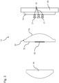
- Fig. 3 shows a schematic representation of a projection headlight 10 of a motor vehicle 1 according to the invention.
- the projection headlight 10 comprises several light sources 20, a projection lens 40 and a condenser lens 30 arranged between the light sources 20 and the projection lens 40.
- a collimator 21 is arranged in front of each light source .
- the collimator 21 is used to generate light with a parallel or an approximately parallel beam path from each light source 20 in direction to the condenser lens 30.
- the condenser lens 30 comprises a flat side 32 and a curved side 34.
- the projection headlight 10 comprises a printed graphic 50, which is printed on the flat side 32 of the condenser lens 10.
- the projection headlight 10 does not have a slide.
- the printed graphic 50 is printed directly onto the surface of the flat side 32 of the condenser lens 10. That means, the graphic 50 to be imaged onto the roadway 5, see Fig. 4 , is printed directly on the flat surface of the condenser lens 30. No additional slide is needed. This saves costs and space.
- the size of the projection headlight 10 can be reduced by the omission of a slide.
- the projection headlight 10 can be produced with smaller dimensions in contrast to a projection headlight 10 according to the prior art shown in Figs. 1 and 2 .
- the projection headlight 10 is more efficient due to lower light losses, since the elimination of the slide eliminates two interfaces at the transition between air and (plastic) slide.
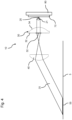
- Fig. 4 a schematic representation of another projection headlight 10 of a motor vehicle 1 according to the invention is shown.
- the projection headlight 10 shown in Fig. 4 has only one light source 20.
- a beam path 25 of the light source 20 of the projection headlight 10 is disclosed.
- the light beam 25 emitted by the light source 20 passes through the collimator 21 which is arranged between the condenser lens 30 and the light source 20.
- the collimator 21 generates a parallel or an approximately parallel beam path in direction to the condenser lens 30.
- the light beam 25 passes through the condenser lens 30 and then immediately the printed graphic 50 on the flat side 32 of the condenser lens 30. After passing the printed graphic 50 the light beam 25 passes the projection lens 40 which projects the printed graphic 50 onto the roadway 5 in front of a vehicle in which the projection headlight 10 is arranged.
- the light sources 20 of the projection headlight 10 are advantageously light-emitting diodes (LED).
- the light sources 20 can be arranged at a circuit board 70 of the projection headlight 10.
- the circuit board 70 can be flexible. Further, the circuit board 70 and therefore the at least one light source 20 can be arranged at a heatsink 80. This allows efficient cooling of the at least one light source 20.
- the printed graphic 50 can be a warning symbol or a traffic sign.
- the projection headlight 10 allows imaging such a warning symbol or a traffic sign onto the roadway 5 in front of the vehicle 1, see Fig 5 .
- the driver of the vehicle 1 can be easily and quickly notified of dangerous situations by imaging the warning symbol or a traffic sign onto the roadway 5.
- the projection headlight 10 and/or the vehicle 1 can comprise an adjustment mechanism for adjusting the position of the projection headlight 10 relative to the vehicle 1. As a result, the position or distance of the projected graphic 55 in front of the vehicle 1 can be adjusted.
- the vehicle 1 can be a motor vehicle, like a lorry or a car. Further, the vehicle 1 can be a motor cycle, a bus or even a train.
Landscapes
- Engineering & Computer Science (AREA)
- General Engineering & Computer Science (AREA)
- Physics & Mathematics (AREA)
- Microelectronics & Electronic Packaging (AREA)
- Optics & Photonics (AREA)
- Non-Portable Lighting Devices Or Systems Thereof (AREA)
Description
- The invention is related to a projection headlight for a vehicle, comprising at least one light source, a projection lens, a condenser lens arranged between the at least one light source and the projection lens, the condenser lens having a flat side and a curved side, and comprising at least one printed graphic arranged between the condenser lens and the projection lens. Furthermore, the invention is related to a vehicle having at least one projection headlight.
- It is known from the prior art that by means of a projection headlight in a motor vehicle a warning symbol can be projected onto the roadway in the principle of a slide projector. For this purpose, a graphic printed on a (plastic) slide is imaged using a projection lens. In order to achieve efficient illumination of the slide, a condenser lens is inserted between the light source and the slide. The slide is arranged between the condenser lens and the projection lens as an independent component. Such a projection headlight is shown in
Figs. 1 and2 . The projection headlight (10) comprises at least one light source (20), a projection lens (40), a condenser lens (30) arranged between the at least one light source (20) and the projection lens (40). The condenser lens (30) is having a flat side (32) and a curved side (34). The projection headlight (10) further comprises a slide (60) with a printed graphic (50). The slide (60) is arranged between the condenser lens (30) and the projection lens (40). The slide (60) is spaced to the condenser lens (30) with a certain distance. - The disadvantage of such a projection headlight is that it is not cost effective and is not very efficient due to light losses at the surfaces of the slide. Because of the arrangement of the slide between the condenser lens and the projection lens the emitted beams of the light source of the projection headlight have to pass through the surfaces of the slide. This causes light losses within the projection headlight.
-
DE 10 2004 058 153 A1 discloses to a lighting device for vehicles with a housing, the front opening of which is covered by a lens. At least one section of the lens has a smooth inside and outside. A light element and a component, which is provided with an identification mark are arranged in the interior of the housing. The identification mark is visible through a section of the light disk that has a smooth outside and inside. -
DE 10 2014 203 313 A1 shows a lighting device for a motor vehicle with at least one light source, the light emission of which provides a light function for the motor vehicle, and with at least one reflector, the lighting device is designed in such a way that a roadway is illuminated or can be illuminated with a light pattern. At least one illuminant for generating the light pattern is arranged behind the at least one reflector in the light exit direction. -
DE 10 2017 104 488 A1 discloses a warning device for an industrial truck, which, arranged on the industrial truck, projects a pictorial information symbol, in particular a pictorial warning symbol, onto a roadway. The warning device being designed as a projector which emits a light source that emits a luminous flux, and an image template of the information symbol to be projected, which can be transilluminated by the luminous flux generated by the light source. In the projector the original image has at least one area which is transparent to the luminous flux of the light source and an area that shades the luminous flux of the light source, and the projector has a free-form lens arranged between the light source and the original image, the free-form lens being designed in such a way that the luminous flux of the light source is incident on the translucent area of the original image is bundled. -
US 2017/0210282 A1 discloses a multifunction assembly comprised of: an outer surface structure containing a side door that supports at least one exterior mirror assembly, an exterior door handle assembly of said door, and an exterior laser emitter which emits a fixed and direct line of laser light downwards on said ground adjacent to the vehicle, indicating an area where the doors open and combines functions associated with other indicator signal devices, sensors and open door commands, and an ultraviolet light emitter device. -
WO 2014/045168 A1 discloses an optical device comprising a first surface with a plurality of micro sized facets, each facet having a respective orientation. Said plurality of facets having an optical axis, which extends parallel to the normal vector to an average orientation of all said respective orientations. The plurality of facets comprising at least a first and a second group of facets, each group is formed by a respective number of at least twenty-five compactly arranged neighboring facets. Each group is arranged to generate during operation a respective, mutually identical whole pattern. Each facet in a respective group is arranged to display a sub-pattern of said respective whole pattern. The whole patterns are mutually superpositioned. - The object of the present invention is to provide a projection headlight for a vehicle, in particular for a motor vehicle, which at least partially avoids the previously described disadvantages. Particularly, it is the object of the present invention to provide a projection headlight for a vehicle, in particular for a motor vehicle, which is economical, which is small in size and which is efficient due to lower light losses. Aforesaid problem is solved by a projection headlight with the features of claim 1 and by a vehicle with the features of claim 8.
- Features and details of the present invention result from the subclaims, the description and the respective drawings. Features and details discussed with respect to the inventive projection headlight are also related to features and details discussed with respect to the vehicle and vice versa.
- According to a first aspect of the invention the problem is solved by a projection headlight for a vehicle, comprising at least one light source, a projection lens, a condenser lens arranged between the at least one light source and the projection lens. The condenser lens is having a flat side and a curved side. The projection headlight further comprises at least one printed graphic arranged between the condenser lens and the projection lens. The at least one printed graphic is printed on the flat side of the condenser lens.
- That means, the graphic to be imaged onto the roadway is printed directly on the flat surface of the condenser lens. The printing can be done in digital printing, screen printing or in particular in pad printing. However, the graphic can also be a coating, for example a colored coating with pigments or dyes and interference coatings, into which the graphic to be generated is introduced by ablation processes, for example removal by means of laser. No additional slide is needed. This saves costs. Advantageously there is no distance between the graphic and the condenser lens. Furthermore, the projection headlight is more efficient due to lower light losses, since the elimination of the slide eliminates two interfaces at the transition between air and (plastic) slide. In addition, the size of the projection headlight can be reduced by the omission of a component.
- The projection headlight can comprise only one light source. Advantageously the projection headlight comprises several light sources, which can all be the same design. The projection headlight may have a housing in which the individual components are arranged.
- Preferred is a projection headlight, wherein a collimator is arranged in front of each light source. That means, each light source has its own collimator which is used to generate light with a parallel or an approximately parallel beam path from each light source in direction to the condenser lens.
- Preferred is a projection headlight, wherein the flat side of the condenser lens faces the projection lens and the curved side of the condenser lens faces the light source. For this purpose, the condenser lens is rotated in contrast to the location of the condenser lens of the projection headlight according to the prior art shown in
Fig. 1 . - The condenser lens is rotated in the existing product by 180 ° and moved to the correct focus position with respect to the desired image. Such an arrangement of the condenser lens in the projection headlight allows that the graphic is located in the beam path of the light of the light source behind the condenser lens.
- The light source can be any type of light sources. Preferred is a projection headlight, wherein the at least one light source is a light-emitting diode (LED). In particular, a projection headlight is preferred, which has a plurality of LEDs.
- The at least one light source can be arranged at a circuit board. Further, the circuit board and therefore the at least one light source can be arranged at a heatsink. This allows efficient cooling of the LEDs.
- Preferred is a projection headlight, wherein the printed graphic is a warning symbol or a traffic sign. Such a projection headlight allows imaging the warning symbol or a traffic sign onto the roadway. Hereby, a driver of a vehicle can be easily and quickly notified of dangerous situations.
- A projection headlight is preferred, which has an adjustment mechanism for adjusting the position of the projection headlight relative to the vehicle. As a result, the position or distance of the projected graphic in front of the vehicle can be adjusted.
- According to a second aspect of the invention the problem is solved by a vehicle having at least one projection headlight, wherein the at least one projection headlight is a projection headlight according to the first aspect of the invention.
- Therefore, the vehicle according to the invention can offer the same advantages as those described for the projection headlight according to the invention.
- A vehicle, in particular a motor vehicle, can comprise at least one projection headlight. Preferred is a vehicle, in particular a motor vehicle, which has two or more projection headlights according to the first aspect of the invention. Such a vehicle allows a driver to project a warning symbol in front of the vehicle onto the road during a driving situation to indicate a danger or an obstacle.
- The projection headlight is positioned as a whole in an opening of a body part of the vehicle. The appearance of the projection headlight is thus characterized by the arrangement of the light sources and the lenses.
- In the following, preferred embodiments of the invention are described based on supportive figures. Thereby, the features described in the claims and in the description can be each single or in every combination essential for the invention. Elements bearing the same function and mode of action are assigned to the same reference signs. It is shown schematically:
- FIG. 1
- a schematic representation of a projection headlight of a motor vehicle according to the prior art,
- FIG. 2
- the projection headlight according to
Fig. 1 showing a beam path of a light source of the projection headlight, - FIG. 3
- a schematic representation of a projection headlight of a motor vehicle according to the invention,
- FIG. 4
- a schematic representation of another projection headlight of a motor vehicle according to the invention, and
- FIG. 5
- a schematic representation of a vehicle with a projection headlight according to the invention.
-
Fig. 1 shows a schematic representation of aprojection headlight 10 of a motor vehicle according to the prior art. InFig. 2 the beam path of thelight source 20 of theprojection headlight 10 according toFig. 1 is shown. -
Fig. 3 shows a schematic representation of aprojection headlight 10 of a motor vehicle 1 according to the invention. Theprojection headlight 10 comprises severallight sources 20, aprojection lens 40 and acondenser lens 30 arranged between thelight sources 20 and theprojection lens 40. In front of each light source acollimator 21 is arranged. Thecollimator 21 is used to generate light with a parallel or an approximately parallel beam path from eachlight source 20 in direction to thecondenser lens 30. Thecondenser lens 30 comprises aflat side 32 and acurved side 34. Further, theprojection headlight 10 comprises a printed graphic 50, which is printed on theflat side 32 of thecondenser lens 10. In contrast to the arrangement of the printed graphic 50 at theslide 60, as shown in theprojection headlight 10 ofFigs. 1 and2 according to the prior art, theprojection headlight 10 according to the invention does not have a slide. The printed graphic 50 is printed directly onto the surface of theflat side 32 of thecondenser lens 10. That means, the graphic 50 to be imaged onto theroadway 5, seeFig. 4 , is printed directly on the flat surface of thecondenser lens 30. No additional slide is needed. This saves costs and space. The size of theprojection headlight 10 can be reduced by the omission of a slide. Theprojection headlight 10 can be produced with smaller dimensions in contrast to aprojection headlight 10 according to the prior art shown inFigs. 1 and2 . Advantageously there is no distance between the printed graphic 50 and thecondenser lens 30. Furthermore, theprojection headlight 10 is more efficient due to lower light losses, since the elimination of the slide eliminates two interfaces at the transition between air and (plastic) slide. - It is possible to arrange two or more printed
graphics 50 on theflat surface 32 of thecondenser lens 30, seeFig. 3 . - In
Fig. 4 a schematic representation of anotherprojection headlight 10 of a motor vehicle 1 according to the invention is shown. In contrast to theprojection headlight 10 shown inFig. 3 theprojection headlight 10 shown inFig. 4 has only onelight source 20. Further, abeam path 25 of thelight source 20 of theprojection headlight 10 is disclosed. Thelight beam 25 emitted by thelight source 20 passes through thecollimator 21 which is arranged between thecondenser lens 30 and thelight source 20. Thecollimator 21 generates a parallel or an approximately parallel beam path in direction to thecondenser lens 30. Thelight beam 25 passes through thecondenser lens 30 and then immediately the printed graphic 50 on theflat side 32 of thecondenser lens 30. After passing the printed graphic 50 thelight beam 25 passes theprojection lens 40 which projects the printed graphic 50 onto theroadway 5 in front of a vehicle in which theprojection headlight 10 is arranged. - The
light sources 20 of theprojection headlight 10 are advantageously light-emitting diodes (LED). Thelight sources 20 can be arranged at acircuit board 70 of theprojection headlight 10. Thecircuit board 70 can be flexible. Further, thecircuit board 70 and therefore the at least onelight source 20 can be arranged at aheatsink 80. This allows efficient cooling of the at least onelight source 20. - The printed graphic 50 can be a warning symbol or a traffic sign. The
projection headlight 10 allows imaging such a warning symbol or a traffic sign onto theroadway 5 in front of the vehicle 1, seeFig 5 . The driver of the vehicle 1 can be easily and quickly notified of dangerous situations by imaging the warning symbol or a traffic sign onto theroadway 5. - The
projection headlight 10 and/or the vehicle 1 can comprise an adjustment mechanism for adjusting the position of theprojection headlight 10 relative to the vehicle 1. As a result, the position or distance of the projected graphic 55 in front of the vehicle 1 can be adjusted. - The vehicle 1 can be a motor vehicle, like a lorry or a car. Further, the vehicle 1 can be a motor cycle, a bus or even a train.
-
- 1
- vehicle
- 5
- roadway
- 10
- projection headlight
- 20
- light source
- 21
- collimator
- 25
- light beam
- 30
- condenser lens
- 32
- flat side
- 34
- curved side
- 40
- projection lens
- 50
- printed graphic
- 55
- projected graphic
- 60
- slide
- 70
- circuit board
- 80
- heatsink
Claims (9)
- Projection headlight (10) for a vehicle (1), comprising at least one light source (20), a projection lens (40), a condenser lens (30) arranged between the at least one light source (20) and the projection lens (40), the condenser lens (30) having a flat side (32) and a curved side (34), and comprising at least one printed graphic (50) arranged between the condenser lens (30) and the projection lens (40),
characterised in
that the at least one printed graphic (50) is printed on the flat side (32) of the condenser lens (10). - Projection headlight (10) according to claim 1,
characterised in
that a collimator (21) is arranged in front of each light source (20). - Projection headlight (10) according to any of the preceding claims, characterised in
that the projection lens (40) is aspherical projection lens. - Projection headlight (10) according to any of the preceding claims, characterised in
that the at least one light source (20) is a light-emitting diode (LED). - Projection headlight (10) according to any of the preceding claims, characterised in
that the at least one light source (20) is arranged at a circuit board (70). - Projection headlight (10) according to claim 5,
characterised in
that the circuit board (70) is arranged at a heatsink (80). - Projection headlight (10) according to any of the preceding claims, characterised in
that the printed graphic (50) is a warning symbol or a traffic sign. - Vehicle (1) having at least one projection headlight,
characterised in
that at least one projection headlight is a projection headlight (10) according to any of the preceding claims. - Vehicle (1) according to claim 8,
characterised in
that the vehicle (1) is a motor vehicle.
Applications Claiming Priority (1)
| Application Number | Priority Date | Filing Date | Title |
|---|---|---|---|
| PCT/EP2018/075860 WO2020064086A1 (en) | 2018-09-25 | 2018-09-25 | Projection headlight for a vehicle and vehicle |
Publications (2)
| Publication Number | Publication Date |
|---|---|
| EP3857119A1 EP3857119A1 (en) | 2021-08-04 |
| EP3857119B1 true EP3857119B1 (en) | 2025-01-01 |
Family
ID=63762468
Family Applications (1)
| Application Number | Title | Priority Date | Filing Date |
|---|---|---|---|
| EP18782344.8A Active EP3857119B1 (en) | 2018-09-25 | 2018-09-25 | Projection headlight for a vehicle and vehicle |
Country Status (4)
| Country | Link |
|---|---|
| US (1) | US11333315B2 (en) |
| EP (1) | EP3857119B1 (en) |
| CN (1) | CN112739950B (en) |
| WO (1) | WO2020064086A1 (en) |
Families Citing this family (5)
| Publication number | Priority date | Publication date | Assignee | Title |
|---|---|---|---|---|
| JP7521437B2 (en) * | 2021-01-22 | 2024-07-24 | 市光工業株式会社 | Vehicle lighting fixtures |
| KR102591435B1 (en) * | 2021-06-23 | 2023-10-19 | 한국광기술원 | Optical system with integrated image filter and vehicle puddle lamp assembly using the same |
| DE102021116638B4 (en) | 2021-06-28 | 2023-05-04 | Datronik Laser & Automation Solutions GmbH & Co. KG | Method and device for processing an optical component for a lighting device of a vehicle |
| JP7753818B2 (en) | 2021-11-12 | 2025-10-15 | 市光工業株式会社 | Lamp units, vehicle lighting fixtures |
| CN114268776A (en) * | 2021-12-17 | 2022-04-01 | 一汽奔腾轿车有限公司 | Traffic sign projection system based on micro-lens array |
Family Cites Families (11)
| Publication number | Priority date | Publication date | Assignee | Title |
|---|---|---|---|---|
| DE102004058153A1 (en) | 2004-04-08 | 2005-10-27 | Hella Kgaa Hueck & Co. | Lighting device for vehicle, has light unit and subassembly that are arranged inside housing, where subassembly includes identification sign that is produced through laser process using gas laser or laser with fixed body |
| TWM324004U (en) * | 2007-06-11 | 2007-12-21 | Yung-Fa Lin | Structure for safety projection lamp of vehicle |
| CN101465965B (en) * | 2007-12-21 | 2011-08-24 | 鸿富锦精密工业(深圳)有限公司 | Miniaturized projection pattern device and mobile phone embedded with the miniaturized projection pattern device |
| US9719655B2 (en) | 2012-09-20 | 2017-08-01 | Philips Lighting Holding B.V. | Optical device with micro sized facets, lens, lighting device, system and method having the same |
| JP6264709B2 (en) * | 2013-12-25 | 2018-01-24 | スタンレー電気株式会社 | Vehicle lighting |
| DE102014203313A1 (en) | 2014-02-25 | 2015-08-27 | Volkswagen Aktiengesellschaft | Lighting device for a motor vehicle |
| JP6328501B2 (en) * | 2014-06-27 | 2018-05-23 | シャープ株式会社 | Lighting device, vehicle headlamp, and vehicle headlamp control system |
| ES2561133B1 (en) | 2014-07-24 | 2016-12-01 | Alejandro Rodriguez Barros | MULTIFUNCTION OUTDOOR REAR VIEW MIRROR WITH LASER ISSUED DEVICE |
| DE102017104488A1 (en) | 2016-07-28 | 2018-02-01 | Linde Material Handling Gmbh | Warning device for an industrial truck |
| CN206592962U (en) * | 2017-01-05 | 2017-10-27 | 郑晓雄 | A kind of LED projection taillight |
| CN206863467U (en) * | 2017-06-30 | 2018-01-09 | 徐佳群 | a projection lamp |
-
2018
- 2018-09-25 CN CN201880097950.7A patent/CN112739950B/en active Active
- 2018-09-25 US US17/278,863 patent/US11333315B2/en active Active
- 2018-09-25 WO PCT/EP2018/075860 patent/WO2020064086A1/en not_active Ceased
- 2018-09-25 EP EP18782344.8A patent/EP3857119B1/en active Active
Also Published As
| Publication number | Publication date |
|---|---|
| CN112739950A (en) | 2021-04-30 |
| WO2020064086A1 (en) | 2020-04-02 |
| CN112739950B (en) | 2024-01-12 |
| US20220034468A1 (en) | 2022-02-03 |
| EP3857119A1 (en) | 2021-08-04 |
| US11333315B2 (en) | 2022-05-17 |
Similar Documents
| Publication | Publication Date | Title |
|---|---|---|
| EP3857119B1 (en) | Projection headlight for a vehicle and vehicle | |
| JP7495539B2 (en) | Optical device and direction indicator | |
| US10551020B2 (en) | Vehicle lamp with acousto-optic device | |
| CN108302477B (en) | Headlamp apparatus for vehicle | |
| CN114206672B (en) | Motor vehicle with ambient lighting | |
| CN111108323A (en) | Projection units, rear view equipment and motor vehicles | |
| US11752927B2 (en) | External cladding component of or for a vehicle and vehicle comprising such an external cladding component | |
| JP7266980B2 (en) | vehicle display | |
| KR102851789B1 (en) | Semi-Dynamic Lamp for Vehicle | |
| CN222887345U (en) | Lighting module and car light | |
| JP7800377B2 (en) | projection device | |
| JP2026074120A (en) | Direction display device |
Legal Events
| Date | Code | Title | Description |
|---|---|---|---|
| STAA | Information on the status of an ep patent application or granted ep patent |
Free format text: STATUS: UNKNOWN |
|
| STAA | Information on the status of an ep patent application or granted ep patent |
Free format text: STATUS: THE INTERNATIONAL PUBLICATION HAS BEEN MADE |
|
| PUAI | Public reference made under article 153(3) epc to a published international application that has entered the european phase |
Free format text: ORIGINAL CODE: 0009012 |
|
| STAA | Information on the status of an ep patent application or granted ep patent |
Free format text: STATUS: REQUEST FOR EXAMINATION WAS MADE |
|
| 17P | Request for examination filed |
Effective date: 20210419 |
|
| AK | Designated contracting states |
Kind code of ref document: A1 Designated state(s): AL AT BE BG CH CY CZ DE DK EE ES FI FR GB GR HR HU IE IS IT LI LT LU LV MC MK MT NL NO PL PT RO RS SE SI SK SM TR |
|
| DAV | Request for validation of the european patent (deleted) | ||
| DAX | Request for extension of the european patent (deleted) | ||
| REG | Reference to a national code |
Ref country code: DE Ref legal event code: R079 Free format text: PREVIOUS MAIN CLASS: F21S0041275000 Ipc: B60Q0001040000 Ref country code: DE Ref legal event code: R079 Ref document number: 602018078139 Country of ref document: DE Free format text: PREVIOUS MAIN CLASS: F21S0041275000 Ipc: B60Q0001040000 |
|
| RIC1 | Information provided on ipc code assigned before grant |
Ipc: F21S 41/43 20180101ALI20231208BHEP Ipc: F21S 41/265 20180101ALI20231208BHEP Ipc: F21S 41/151 20180101ALI20231208BHEP Ipc: F21S 41/143 20180101ALI20231208BHEP Ipc: F21W 103/60 20180101ALI20231208BHEP Ipc: F21S 41/275 20180101ALI20231208BHEP Ipc: B60Q 1/04 20060101AFI20231208BHEP |
|
| STAA | Information on the status of an ep patent application or granted ep patent |
Free format text: STATUS: EXAMINATION IS IN PROGRESS |
|
| 17Q | First examination report despatched |
Effective date: 20240229 |
|
| GRAP | Despatch of communication of intention to grant a patent |
Free format text: ORIGINAL CODE: EPIDOSNIGR1 |
|
| STAA | Information on the status of an ep patent application or granted ep patent |
Free format text: STATUS: GRANT OF PATENT IS INTENDED |
|
| GRAS | Grant fee paid |
Free format text: ORIGINAL CODE: EPIDOSNIGR3 |
|
| INTG | Intention to grant announced |
Effective date: 20241029 |
|
| GRAA | (expected) grant |
Free format text: ORIGINAL CODE: 0009210 |
|
| STAA | Information on the status of an ep patent application or granted ep patent |
Free format text: STATUS: THE PATENT HAS BEEN GRANTED |
|
| AK | Designated contracting states |
Kind code of ref document: B1 Designated state(s): AL AT BE BG CH CY CZ DE DK EE ES FI FR GB GR HR HU IE IS IT LI LT LU LV MC MK MT NL NO PL PT RO RS SE SI SK SM TR |
|
| REG | Reference to a national code |
Ref country code: GB Ref legal event code: FG4D |
|
| REG | Reference to a national code |
Ref country code: DE Ref legal event code: R096 Ref document number: 602018078139 Country of ref document: DE |
|
| REG | Reference to a national code |
Ref country code: CH Ref legal event code: EP |
|
| REG | Reference to a national code |
Ref country code: IE Ref legal event code: FG4D |
|
| REG | Reference to a national code |
Ref country code: LT Ref legal event code: MG9D |
|
| REG | Reference to a national code |
Ref country code: NL Ref legal event code: MP Effective date: 20250101 |
|
| REG | Reference to a national code |
Ref country code: AT Ref legal event code: MK05 Ref document number: 1755930 Country of ref document: AT Kind code of ref document: T Effective date: 20250101 |
|
| PG25 | Lapsed in a contracting state [announced via postgrant information from national office to epo] |
Ref country code: NL Free format text: LAPSE BECAUSE OF FAILURE TO SUBMIT A TRANSLATION OF THE DESCRIPTION OR TO PAY THE FEE WITHIN THE PRESCRIBED TIME-LIMIT Effective date: 20250101 |
|
| PG25 | Lapsed in a contracting state [announced via postgrant information from national office to epo] |
Ref country code: FI Free format text: LAPSE BECAUSE OF FAILURE TO SUBMIT A TRANSLATION OF THE DESCRIPTION OR TO PAY THE FEE WITHIN THE PRESCRIBED TIME-LIMIT Effective date: 20250101 |
|
| PG25 | Lapsed in a contracting state [announced via postgrant information from national office to epo] |
Ref country code: PL Free format text: LAPSE BECAUSE OF FAILURE TO SUBMIT A TRANSLATION OF THE DESCRIPTION OR TO PAY THE FEE WITHIN THE PRESCRIBED TIME-LIMIT Effective date: 20250101 |
|
| PG25 | Lapsed in a contracting state [announced via postgrant information from national office to epo] |
Ref country code: ES Free format text: LAPSE BECAUSE OF FAILURE TO SUBMIT A TRANSLATION OF THE DESCRIPTION OR TO PAY THE FEE WITHIN THE PRESCRIBED TIME-LIMIT Effective date: 20250101 |
|
| PG25 | Lapsed in a contracting state [announced via postgrant information from national office to epo] |
Ref country code: NO Free format text: LAPSE BECAUSE OF FAILURE TO SUBMIT A TRANSLATION OF THE DESCRIPTION OR TO PAY THE FEE WITHIN THE PRESCRIBED TIME-LIMIT Effective date: 20250401 Ref country code: IS Free format text: LAPSE BECAUSE OF FAILURE TO SUBMIT A TRANSLATION OF THE DESCRIPTION OR TO PAY THE FEE WITHIN THE PRESCRIBED TIME-LIMIT Effective date: 20250501 |
|
| PG25 | Lapsed in a contracting state [announced via postgrant information from national office to epo] |
Ref country code: HR Free format text: LAPSE BECAUSE OF FAILURE TO SUBMIT A TRANSLATION OF THE DESCRIPTION OR TO PAY THE FEE WITHIN THE PRESCRIBED TIME-LIMIT Effective date: 20250101 |
|
| PG25 | Lapsed in a contracting state [announced via postgrant information from national office to epo] |
Ref country code: LV Free format text: LAPSE BECAUSE OF FAILURE TO SUBMIT A TRANSLATION OF THE DESCRIPTION OR TO PAY THE FEE WITHIN THE PRESCRIBED TIME-LIMIT Effective date: 20250101 Ref country code: PT Free format text: LAPSE BECAUSE OF FAILURE TO SUBMIT A TRANSLATION OF THE DESCRIPTION OR TO PAY THE FEE WITHIN THE PRESCRIBED TIME-LIMIT Effective date: 20250502 |
|
| PG25 | Lapsed in a contracting state [announced via postgrant information from national office to epo] |
Ref country code: GR Free format text: LAPSE BECAUSE OF FAILURE TO SUBMIT A TRANSLATION OF THE DESCRIPTION OR TO PAY THE FEE WITHIN THE PRESCRIBED TIME-LIMIT Effective date: 20250402 Ref country code: BG Free format text: LAPSE BECAUSE OF FAILURE TO SUBMIT A TRANSLATION OF THE DESCRIPTION OR TO PAY THE FEE WITHIN THE PRESCRIBED TIME-LIMIT Effective date: 20250101 |
|
| PG25 | Lapsed in a contracting state [announced via postgrant information from national office to epo] |
Ref country code: AT Free format text: LAPSE BECAUSE OF FAILURE TO SUBMIT A TRANSLATION OF THE DESCRIPTION OR TO PAY THE FEE WITHIN THE PRESCRIBED TIME-LIMIT Effective date: 20250101 |
|
| PG25 | Lapsed in a contracting state [announced via postgrant information from national office to epo] |
Ref country code: CZ Free format text: LAPSE BECAUSE OF FAILURE TO SUBMIT A TRANSLATION OF THE DESCRIPTION OR TO PAY THE FEE WITHIN THE PRESCRIBED TIME-LIMIT Effective date: 20250101 |
|
| PG25 | Lapsed in a contracting state [announced via postgrant information from national office to epo] |
Ref country code: SE Free format text: LAPSE BECAUSE OF FAILURE TO SUBMIT A TRANSLATION OF THE DESCRIPTION OR TO PAY THE FEE WITHIN THE PRESCRIBED TIME-LIMIT Effective date: 20250101 |
|
| REG | Reference to a national code |
Ref country code: DE Ref legal event code: R097 Ref document number: 602018078139 Country of ref document: DE |
|
| PG25 | Lapsed in a contracting state [announced via postgrant information from national office to epo] |
Ref country code: SM Free format text: LAPSE BECAUSE OF FAILURE TO SUBMIT A TRANSLATION OF THE DESCRIPTION OR TO PAY THE FEE WITHIN THE PRESCRIBED TIME-LIMIT Effective date: 20250101 |
|
| PG25 | Lapsed in a contracting state [announced via postgrant information from national office to epo] |
Ref country code: DK Free format text: LAPSE BECAUSE OF FAILURE TO SUBMIT A TRANSLATION OF THE DESCRIPTION OR TO PAY THE FEE WITHIN THE PRESCRIBED TIME-LIMIT Effective date: 20250101 |
|
| PGFP | Annual fee paid to national office [announced via postgrant information from national office to epo] |
Ref country code: DE Payment date: 20250702 Year of fee payment: 8 |
|
| PG25 | Lapsed in a contracting state [announced via postgrant information from national office to epo] |
Ref country code: IT Free format text: LAPSE BECAUSE OF FAILURE TO SUBMIT A TRANSLATION OF THE DESCRIPTION OR TO PAY THE FEE WITHIN THE PRESCRIBED TIME-LIMIT Effective date: 20250101 |
|
| PG25 | Lapsed in a contracting state [announced via postgrant information from national office to epo] |
Ref country code: EE Free format text: LAPSE BECAUSE OF FAILURE TO SUBMIT A TRANSLATION OF THE DESCRIPTION OR TO PAY THE FEE WITHIN THE PRESCRIBED TIME-LIMIT Effective date: 20250101 |
|
| PG25 | Lapsed in a contracting state [announced via postgrant information from national office to epo] |
Ref country code: RO Free format text: LAPSE BECAUSE OF FAILURE TO SUBMIT A TRANSLATION OF THE DESCRIPTION OR TO PAY THE FEE WITHIN THE PRESCRIBED TIME-LIMIT Effective date: 20250101 |
|
| PG25 | Lapsed in a contracting state [announced via postgrant information from national office to epo] |
Ref country code: SK Free format text: LAPSE BECAUSE OF FAILURE TO SUBMIT A TRANSLATION OF THE DESCRIPTION OR TO PAY THE FEE WITHIN THE PRESCRIBED TIME-LIMIT Effective date: 20250101 |
|
| PLBE | No opposition filed within time limit |
Free format text: ORIGINAL CODE: 0009261 |
|
| STAA | Information on the status of an ep patent application or granted ep patent |
Free format text: STATUS: NO OPPOSITION FILED WITHIN TIME LIMIT |
|
| REG | Reference to a national code |
Ref country code: CH Ref legal event code: L10 Free format text: ST27 STATUS EVENT CODE: U-0-0-L10-L00 (AS PROVIDED BY THE NATIONAL OFFICE) Effective date: 20251112 |
|
| 26N | No opposition filed |
Effective date: 20251002 |
|
| REG | Reference to a national code |
Ref country code: CH Ref legal event code: H13 Free format text: ST27 STATUS EVENT CODE: U-0-0-H10-H13 (AS PROVIDED BY THE NATIONAL OFFICE) Effective date: 20260425 |