EP3857017B1 - High pressure cable head connector - Google Patents
High pressure cable head connector Download PDFInfo
- Publication number
- EP3857017B1 EP3857017B1 EP19772704.3A EP19772704A EP3857017B1 EP 3857017 B1 EP3857017 B1 EP 3857017B1 EP 19772704 A EP19772704 A EP 19772704A EP 3857017 B1 EP3857017 B1 EP 3857017B1
- Authority
- EP
- European Patent Office
- Prior art keywords
- cable
- bevel
- cavity
- connector device
- ring
- Prior art date
- Legal status (The legal status is an assumption and is not a legal conclusion. Google has not performed a legal analysis and makes no representation as to the accuracy of the status listed.)
- Active
Links
Images


Classifications
-
- E—FIXED CONSTRUCTIONS
- E21—EARTH OR ROCK DRILLING; MINING
- E21B—EARTH OR ROCK DRILLING; OBTAINING OIL, GAS, WATER, SOLUBLE OR MELTABLE MATERIALS OR A SLURRY OF MINERALS FROM WELLS
- E21B17/00—Drilling rods or pipes; Flexible drill strings; Kellies; Drill collars; Sucker rods; Cables; Casings; Tubings
- E21B17/02—Couplings; joints
- E21B17/023—Arrangements for connecting cables or wirelines to downhole devices
-
- E—FIXED CONSTRUCTIONS
- E21—EARTH OR ROCK DRILLING; MINING
- E21B—EARTH OR ROCK DRILLING; OBTAINING OIL, GAS, WATER, SOLUBLE OR MELTABLE MATERIALS OR A SLURRY OF MINERALS FROM WELLS
- E21B17/00—Drilling rods or pipes; Flexible drill strings; Kellies; Drill collars; Sucker rods; Cables; Casings; Tubings
- E21B17/02—Couplings; joints
- E21B17/04—Couplings; joints between rod or the like and bit or between rod and rod or the like
-
- F—MECHANICAL ENGINEERING; LIGHTING; HEATING; WEAPONS; BLASTING
- F16—ENGINEERING ELEMENTS AND UNITS; GENERAL MEASURES FOR PRODUCING AND MAINTAINING EFFECTIVE FUNCTIONING OF MACHINES OR INSTALLATIONS; THERMAL INSULATION IN GENERAL
- F16L—PIPES; JOINTS OR FITTINGS FOR PIPES; SUPPORTS FOR PIPES, CABLES OR PROTECTIVE TUBING; MEANS FOR THERMAL INSULATION IN GENERAL
- F16L19/00—Joints in which sealing surfaces are pressed together by means of a member, e.g. a swivel nut, screwed on, or into, one of the joint parts
- F16L19/08—Joints in which sealing surfaces are pressed together by means of a member, e.g. a swivel nut, screwed on, or into, one of the joint parts with metal rings which bite into the wall of the pipe
- F16L19/10—Joints in which sealing surfaces are pressed together by means of a member, e.g. a swivel nut, screwed on, or into, one of the joint parts with metal rings which bite into the wall of the pipe the profile of the ring being altered
- F16L19/103—Joints in which sealing surfaces are pressed together by means of a member, e.g. a swivel nut, screwed on, or into, one of the joint parts with metal rings which bite into the wall of the pipe the profile of the ring being altered with more than one ring per pipe end being used
-
- F—MECHANICAL ENGINEERING; LIGHTING; HEATING; WEAPONS; BLASTING
- F16—ENGINEERING ELEMENTS AND UNITS; GENERAL MEASURES FOR PRODUCING AND MAINTAINING EFFECTIVE FUNCTIONING OF MACHINES OR INSTALLATIONS; THERMAL INSULATION IN GENERAL
- F16L—PIPES; JOINTS OR FITTINGS FOR PIPES; SUPPORTS FOR PIPES, CABLES OR PROTECTIVE TUBING; MEANS FOR THERMAL INSULATION IN GENERAL
- F16L19/00—Joints in which sealing surfaces are pressed together by means of a member, e.g. a swivel nut, screwed on, or into, one of the joint parts
- F16L19/08—Joints in which sealing surfaces are pressed together by means of a member, e.g. a swivel nut, screwed on, or into, one of the joint parts with metal rings which bite into the wall of the pipe
- F16L19/10—Joints in which sealing surfaces are pressed together by means of a member, e.g. a swivel nut, screwed on, or into, one of the joint parts with metal rings which bite into the wall of the pipe the profile of the ring being altered
- F16L19/106—Joints in which sealing surfaces are pressed together by means of a member, e.g. a swivel nut, screwed on, or into, one of the joint parts with metal rings which bite into the wall of the pipe the profile of the ring being altered the ring comprising a shoulder against which the pipe end abuts
-
- H—ELECTRICITY
- H02—GENERATION; CONVERSION OR DISTRIBUTION OF ELECTRIC POWER
- H02G—INSTALLATION OF ELECTRIC CABLES OR LINES, OR OF COMBINED OPTICAL AND ELECTRIC CABLES OR LINES
- H02G15/00—Cable fittings
- H02G15/02—Cable terminations
- H02G15/04—Cable-end sealings
-
- H—ELECTRICITY
- H02—GENERATION; CONVERSION OR DISTRIBUTION OF ELECTRIC POWER
- H02G—INSTALLATION OF ELECTRIC CABLES OR LINES, OR OF COMBINED OPTICAL AND ELECTRIC CABLES OR LINES
- H02G3/00—Installations of electric cables or lines or protective tubing therefor in or on buildings, equivalent structures or vehicles
- H02G3/02—Details
- H02G3/06—Joints for connecting lengths of protective tubing or channels, to each other or to casings, e.g. to distribution boxes; Ensuring electrical continuity in the joint
- H02G3/0616—Joints for connecting tubing to casing
- H02G3/0625—Joints for connecting tubing to casing with means for preventing disengagement of conductors
- H02G3/0658—Joints for connecting tubing to casing with means for preventing disengagement of conductors with means constricting the conductor-insulation
-
- H—ELECTRICITY
- H02—GENERATION; CONVERSION OR DISTRIBUTION OF ELECTRIC POWER
- H02G—INSTALLATION OF ELECTRIC CABLES OR LINES, OR OF COMBINED OPTICAL AND ELECTRIC CABLES OR LINES
- H02G3/00—Installations of electric cables or lines or protective tubing therefor in or on buildings, equivalent structures or vehicles
- H02G3/02—Details
- H02G3/06—Joints for connecting lengths of protective tubing or channels, to each other or to casings, e.g. to distribution boxes; Ensuring electrical continuity in the joint
- H02G3/0616—Joints for connecting tubing to casing
- H02G3/0625—Joints for connecting tubing to casing with means for preventing disengagement of conductors
- H02G3/0675—Joints for connecting tubing to casing with means for preventing disengagement of conductors with bolts operating in a direction parallel to the conductors
Definitions
- the present invention relates to a high-pressure cable head connector, e.g. for connecting downhole cable with gauge for use in downhole completion.
- a cable head is part of the downhole gauge tool used for connecting a downhole cable to a gauge and need to ensure and protect connection of the downhole cable with the gauge with a double barrier metal to metal seals.
- US 2 459 608 discloses a coupling, wherein a tube is secured to the coupling by metal disks forced by the nut into gripping engagement with the tube and wherein a sealing gasket is deformed by the closing of the coupling so as to provide a tight seal between the coupling and the tube.
- the frustoconical shape disk members act on the gasket to create the sealing.
- GB1602356 discloses a pipe coupling comprising a frustoconical shaped sealing ring disk to be compressed in the axial direction to form a sealing in an annular recess.
- GB1317484 discloses a coupling including an annular, initially generally frustoconical, crimping member acting on a sealing element.
- the objective problem may be defined as to create a connection seal with a high pressure integrity both outside against housing and inside against metal pipe or cable.
- the objective problem to be solved according to the preferred embodiment of the invention is how to create a double metal connection seal, outside against housing and inside against a pipe or cable with a hard, usually metal, surface. Note that "cable” in the present specification should also be interpreted as "pipe” under comparable situations
- the present invention relates generally to metal to metal seal and particularly to a resilient metal bevel seal embedded between a cable head housing and a 1 ⁇ 4" downhole tubing encapsulated cable (TEC). More specifically the present invention is characterized as presented in the accompanying claims.
- This provides a seal interface for sealing against outside pressure and in the same time for inside pressure of the well fluid in conditions of high pressure and high temperature. This is provided by forcing the sealing ring both outward into the connector housing and inward to the cable surface, the cable surface being made from a metal or another material having similar characteristics. In a preferred embodiment two rings are used for redundancy.
- the present invention utilizes ring shaped bevel springs that are compressed to a predetermined deflection, generating a sealing stress by the resilient bevel spring seal shape. This way a compact connector is provided using less parts and thus minimizing the risk of failure, and that is easy to assemble, thus reducing the time to rig a system.
- the components may be used as is without contact preparations of the cable.
- the barriers provided by the present invention are thus obtained by radial deformation and elastic stress in the contact area. direct on the sealing elements, without any intermediate part.
- HPHT high pressure, high temperature
- the sealed connector includes a first connector part 1 and a second connector part 5 adapted to be locked or screwed together applying an axial force towards each other.
- two bevel rings 2 are positioned between the first and second parts in the axial direction.
- the front end of the second connector part 5 and the inner surface of the first connector part have radially plane section and the bevel rings 2 have a frustoconical shape defining an angle relative to the radial and axial directions.
- the bevel rings are tilted in opposite directions toward each other with a stopper ring 3 between them.
- the stopper ring limiting how much the shape of the bevel ring can change then the connector parts are pressed together, limiting the force toward, and deformation of, the outer part of the cable.
- the front end of the second connector part 4 includes a low friction element surface 4a to be able to rotate relative to the bevel ring if screwed into the connector.
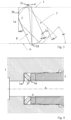
- Figure 3 illustrates the function of the bevel rings 2.
- the bevel ring cross section is shown as a rounded essentially rectangular shape in two situations, the uncompressed position 7 and the compressed position 8.
- the bevel ring 2 in the illustrated example 7 has an angle of 45° relative to the longitudinal axis corresponding to both the inner house surface of the first connector part 1 and the outer surface of the cable 6.
- the bevel ring is tilted, e.g.
- the bevel seals 2 are embedded into a housing 1 and compressed against a cable head housing 6 shoulder, preferably by a metallic threaded locker part until the flat surface of the bevel seals are mating with flat surface from cable head housing respective to the flat surface of the locker part.
- the rounded rectangular shape is preferably about 2:1 ratio between radial dimension and thickness, and may include a cut off edge 2a toward the front end of the second connector part, having an angle, e.g. 25° in the case when the bevel ring is tilted by 45°, from the bevel seal surface.
- This is to receive the front end 4 of the second connector (not shown in figure 3 ), and, when a tilt of 5° has been applied the cutoff edge 2a is perpendicular to the longitudinal direction and thus parallel to the front end 4 of the second connector part 5. This will stop the tilting at 5 degrees, before amplitude point of rotation, thus protecting the cable 6 and housing 1.
- a similar cutoff edge may also be provided on the edge 2b interacting with the inner surface 1a of the first connector part. This will create a controlled contact stress to avoid the TEC to be deformed on the inner wall against cable.
- the stopper 3 illustrated in figure 2 may have the same function in providing a bed stopping for the tilt at a certain angle where the sealing is obtained without applying more stress or deforming the bevel seal, cable or housing more than an allowed degree.
- Bevel seals will have an axial movement and in the same time a rotation with 20 degrees, stopping rotation with 5 degrees before amplitude of the movement between the bevel seal and housing and respective downhole cable. This way a spring back force is obtained as well as protection of the parts.
- Compressed bevel seal system is capable to provide a pressure integrity mechanism which form a pressure seal on a tubular wall both outside and inside.
- a locking mechanism may be used to avoid relaxing the bevel seals by unscrewing locking part.
- Figure 4 and 5 illustrates alternative embodiments where figure 4 only includes one bevel seal 2, compressed between the front surface 4 of the second connector part and the inner surface 1a of the first connector part 1.
- figure 5 a similar solution is shown where two bevel rings are used, providing a redundancy in the sealing.
- the rectangular cross sections show cutoffs on both sides of the bevel rings, both on the inner surface 1a and the front surface 4.
- the present invention thus relates to a high pressure cable head connector, e.g. for connecting downhole cable to a measurement device, e.g. a pressure sensor, for use in downhole completion, as set out in claim 1.
- the sealing cable connection device is made for high pressure applications including a first connector part and a second connector part including an axial channel for allowing a cable or pipe to extend, where the cable preferably has an outer surface made of metal or another hard material that can be deformed when subject to a force.
- the first connector part 1 having a cylindrical channel with a radially oriented inner surface 1a and the second connector part 5 being adapted to be introduced into said channel and having a corresponding shape in the radial direction, said second connector part having a radially oriented front end surface 4a.
- the cavity being coaxially oriented around the cable channel 6.
- the first and second connector parts include locking means being adapted to applying an axial force and lock the parts together after connecting.
- the inner volume of said receiving cavity includes at least one bevel ring 2 having radial dimensions corresponding to the radial dimensions of the cavity between the cable and the outer walls of the cavity, the bevel rings preferably having an essentially frustoconical shape in the longitudinal direction.
- the outer parts of said bevel rings are forced into said cavity wall as well as into a cable or pipe in said cable channel, thus deforming the material in the cavity wall and cable.
- the cavity walls and bevel ring(s) are made from a metal and the cable or pipe is a tubing encapsuled cable with a hard or metal outer surface.
- the material for tubing encapsulate cable is nickel alloy 625 or nickel alloy 825 and the bevel seal rings are made from nickel alloy 718.
- Other bevel ring shapes may also be contemplated as long as they provide a force in the radial direction when subject to an axial force
- the first and second connector parts may be threaded so that the axial force is applied by screwing the parts together, and/or may be provided with other locking mechanisms.
- the bevel rings are constituted by springs exerting high contact stress equal for contact between said outer wall of said cavity and the ring and outer surface of the cable.
- the bevel rings may be adapted to, when compressed, act like an energized spring who exerts high contact stress equal to compensate thermal expansion of the parts.
- the present invention thus provides a first seal barrier for sealing between a connector housing 1 and cable pipe 6 for protecting cable connection against well fluid.
- a second seal barrier is used to ensure redundancy of the primary seal. This is obtained using one or more bevel rings 2.
- Preferably two bevel rings are used being oriented back to back.
- two bevel rings may provide a double bevel seal technology based on metal to metal sealing for HPHT (High Pressure, High Temperature) environment based on the shape of the seal, preferably being suitable for 0,17 GPa (25000 psi) and 225 C degrees.
- the at least one bevel rings are rotated around cross intersection of the shape diagonals, as shown and discussed in relation to figure 3 in the controlled manner to ensure maximum contact stress against tubing encapsulate cable and in the same time against outer wall of the cavity when subject to an axial force.
- the bevel ring or rings are preferably stopped all the time in the same, predetermined position as provided by the cut off edge 2a or by the limiter 3 in figure 2 .
Landscapes
- Engineering & Computer Science (AREA)
- Geology (AREA)
- Life Sciences & Earth Sciences (AREA)
- Mining & Mineral Resources (AREA)
- Mechanical Engineering (AREA)
- General Engineering & Computer Science (AREA)
- General Life Sciences & Earth Sciences (AREA)
- Fluid Mechanics (AREA)
- Environmental & Geological Engineering (AREA)
- Geochemistry & Mineralogy (AREA)
- Physics & Mathematics (AREA)
- Architecture (AREA)
- Civil Engineering (AREA)
- Structural Engineering (AREA)
- Cable Accessories (AREA)
- Gasket Seals (AREA)
- Processing Of Terminals (AREA)
Description
- The present invention relates to a high-pressure cable head connector, e.g. for connecting downhole cable with gauge for use in downhole completion.
- A cable head is part of the downhole gauge tool used for connecting a downhole cable to a gauge and need to ensure and protect connection of the downhole cable with the gauge with a double barrier metal to metal seals.
- Known solutions for high pressure environments have included complicated structures with a number of sealing rings. One example of the prior art is presented in
figure 1 where tworings 01 are forced in the radial direction when theconnector parts sealing rings 01 sufficient contact with the cable surface, and the number of parts needed for providing two pressure barriers increases the risk of failure. Examples showing such solutions are well known within the field and may be found inGB2287997 US5823256 ,US3445128 andUS3325192 . A slightly different solution is presented inUS3985379 where a frustoconical ring is used to increase the force on part of the sleeve toward the pipe, this increasing the friction, but still the limitations discussed above apply as the force is distributed to avoid deforming the pipe material. - Additionally the following documents are relevant prior art.
-
US 2 459 608 discloses a coupling, wherein a tube is secured to the coupling by metal disks forced by the nut into gripping engagement with the tube and wherein a sealing gasket is deformed by the closing of the coupling so as to provide a tight seal between the coupling and the tube. The frustoconical shape disk members act on the gasket to create the sealing. -
GB1602356 -
GB1317484 - It is an object of the present invention to provide a relatively inexpensive connector with high pressure integrity, which is easily assembled in offshore applications while reducing the required qualification of the users. More specifically the objective problem may be defined as to create a connection seal with a high pressure integrity both outside against housing and inside against metal pipe or cable. The objective problem to be solved according to the preferred embodiment of the invention is how to create a double metal connection seal, outside against housing and inside against a pipe or cable with a hard, usually metal, surface. Note that "cable" in the present specification should also be interpreted as "pipe" under comparable situations
- The present invention relates generally to metal to metal seal and particularly to a resilient metal bevel seal embedded between a cable head housing and a ¼" downhole tubing encapsulated cable (TEC). More specifically the present invention is characterized as presented in the accompanying claims.
- This provides a seal interface for sealing against outside pressure and in the same time for inside pressure of the well fluid in conditions of high pressure and high temperature. This is provided by forcing the sealing ring both outward into the connector housing and inward to the cable surface, the cable surface being made from a metal or another material having similar characteristics. In a preferred embodiment two rings are used for redundancy.
- The present invention utilizes ring shaped bevel springs that are compressed to a predetermined deflection, generating a sealing stress by the resilient bevel spring seal shape. This way a compact connector is provided using less parts and thus minimizing the risk of failure, and that is easy to assemble, thus reducing the time to rig a system. The components may be used as is without contact preparations of the cable.
- The barriers provided by the present invention are thus obtained by radial deformation and elastic stress in the contact area. direct on the sealing elements, without any intermediate part.
- It is essential for the present invention is to achieve two barriers of the same level and in the same time, both sealing against HPHT (high pressure, high temperature) fluid, outside against the housing and inside against the pipe from tubing encased cable (TEC).
- In addition:
- Seals are deformed in control manner and all the time in the same fixed and locked position.
- The two sealing barriers testable independent in the flow direction.
- Both barriers are equals in terms of capability of sealing against fluid with high pressure and high temperature
- Both barriers have a controlled deformation to achieve the same contact stress.
- Both seals have capability to seal HPHT in both direction, from right to left and vice versa.
- The invention will be described more in detail with reference to the accompanying drawings, illustrating the invention by way of examples.
- Fig. 1
- illustrates the prior art.
- Fig. 2
- illustrates a longitudinal cross section of the preferred embodiment of the invention.
- Fig. 3
- illustrates the sealing mechanism of the invention.
- Fig. 4
- illustrates a simplified embodiment of the invention.
- Fig. 5
- illustrates an alternative embodiment of the invention.
- As is illustrated in
figure 2 the sealed connector according to the invention includes a first connector part 1 and asecond connector part 5 adapted to be locked or screwed together applying an axial force towards each other. A cable orpipe 6, preferably a TEC or other cables with a hard, outer surface, extends through the connector. - As can be seen from the drawing two
bevel rings 2 are positioned between the first and second parts in the axial direction. The front end of thesecond connector part 5 and the inner surface of the first connector part have radially plane section and thebevel rings 2 have a frustoconical shape defining an angle relative to the radial and axial directions. Infigure 2 the bevel rings are tilted in opposite directions toward each other with astopper ring 3 between them. The stopper ring limiting how much the shape of the bevel ring can change then the connector parts are pressed together, limiting the force toward, and deformation of, the outer part of the cable. Preferably the front end of thesecond connector part 4 includes a lowfriction element surface 4a to be able to rotate relative to the bevel ring if screwed into the connector. -
Figure 3 illustrates the function of thebevel rings 2. The bevel ring cross section is shown as a rounded essentially rectangular shape in two situations, theuncompressed position 7 and thecompressed position 8. Before the compression thebevel ring 2 in the illustrated example 7 has an angle of 45° relative to the longitudinal axis corresponding to both the inner house surface of the first connector part 1 and the outer surface of thecable 6. After being subject to a longitudinal force toward the inner wall 1a of the first connector part by thefront end 4 of thesecond connector part 5 the bevel ring is tilted, e.g. by 5° as illustrated in thecompressed position 8, in which case the outer edge 2c of the bevel ring is forced in the radial direction into the inner surface of the first connector part 1 and theinner edge 2d toward the outer surface of thecable 6. This forces a close connection between the surfaces and the bevel ring and thus sealing the connection between the first connector part and the cable. - Thus, when the axial pressure is applied the
bevel seals 2 are embedded into a housing 1 and compressed against acable head housing 6 shoulder, preferably by a metallic threaded locker part until the flat surface of the bevel seals are mating with flat surface from cable head housing respective to the flat surface of the locker part. - As can be seen from the cross section of the bevel ring in
figure 3 the rounded rectangular shape is preferably about 2:1 ratio between radial dimension and thickness, and may include a cut offedge 2a toward the front end of the second connector part, having an angle, e.g. 25° in the case when the bevel ring is tilted by 45°, from the bevel seal surface. This is to receive thefront end 4 of the second connector (not shown infigure 3 ), and, when a tilt of 5° has been applied thecutoff edge 2a is perpendicular to the longitudinal direction and thus parallel to thefront end 4 of thesecond connector part 5. This will stop the tilting at 5 degrees, before amplitude point of rotation, thus protecting thecable 6 and housing 1. A similar cutoff edge may also be provided on theedge 2b interacting with the inner surface 1a of the first connector part. This will create a controlled contact stress to avoid the TEC to be deformed on the inner wall against cable. - The
stopper 3 illustrated infigure 2 may have the same function in providing a bed stopping for the tilt at a certain angle where the sealing is obtained without applying more stress or deforming the bevel seal, cable or housing more than an allowed degree. - Bevel seals will have an axial movement and in the same time a rotation with 20 degrees, stopping rotation with 5 degrees before amplitude of the movement between the bevel seal and housing and respective downhole cable. This way a spring back force is obtained as well as protection of the parts.
- During the movement and after, a spring back force will exert uniform pressure on the sealing interface and keeps a preset load on the seal with an equal distribution outside to the housing and inside to the cable pipe. Compressed bevel seal system is capable to provide a pressure integrity mechanism which form a pressure seal on a tubular wall both outside and inside. A locking mechanism may be used to avoid relaxing the bevel seals by unscrewing locking part.
-
Figure 4 and5 illustrates alternative embodiments wherefigure 4 only includes onebevel seal 2, compressed between thefront surface 4 of the second connector part and the inner surface 1a of the first connector part 1. Infigure 5 a similar solution is shown where two bevel rings are used, providing a redundancy in the sealing. In these figures the rectangular cross sections show cutoffs on both sides of the bevel rings, both on the inner surface 1a and thefront surface 4. - The present invention thus relates to a high pressure cable head connector, e.g. for connecting downhole cable to a measurement device, e.g. a pressure sensor, for use in downhole completion, as set out in claim 1.
- The sealing cable connection device is made for high pressure applications including a first connector part and a second connector part including an axial channel for allowing a cable or pipe to extend, where the cable preferably has an outer surface made of metal or another hard material that can be deformed when subject to a force. The first connector part 1 having a cylindrical channel with a radially oriented inner surface 1a and the
second connector part 5 being adapted to be introduced into said channel and having a corresponding shape in the radial direction, said second connector part having a radially orientedfront end surface 4a. The cavity being coaxially oriented around thecable channel 6. The first and second connector parts include locking means being adapted to applying an axial force and lock the parts together after connecting. - The inner volume of said receiving cavity includes at least one
bevel ring 2 having radial dimensions corresponding to the radial dimensions of the cavity between the cable and the outer walls of the cavity, the bevel rings preferably having an essentially frustoconical shape in the longitudinal direction. At the application of said axial force the outer parts of said bevel rings are forced into said cavity wall as well as into a cable or pipe in said cable channel, thus deforming the material in the cavity wall and cable. Preferably the cavity walls and bevel ring(s) are made from a metal and the cable or pipe is a tubing encapsuled cable with a hard or metal outer surface. Preferably the material for tubing encapsulate cable is nickel alloy 625 or nickel alloy 825 and the bevel seal rings are made from nickel alloy 718. Other bevel ring shapes may also be contemplated as long as they provide a force in the radial direction when subject to an axial force - The first and second connector parts may be threaded so that the axial force is applied by screwing the parts together, and/or may be provided with other locking mechanisms.
- Preferably the bevel rings are constituted by springs exerting high contact stress equal for contact between said outer wall of said cavity and the ring and outer surface of the cable. The bevel rings may be adapted to, when compressed, act like an energized spring who exerts high contact stress equal to compensate thermal expansion of the parts.
- The present invention thus provides a first seal barrier for sealing between a connector housing 1 and
cable pipe 6 for protecting cable connection against well fluid. Preferably a second seal barrier is used to ensure redundancy of the primary seal. This is obtained using one or more bevel rings 2. Preferably two bevel rings are used being oriented back to back. Thus two bevel rings may provide a double bevel seal technology based on metal to metal sealing for HPHT (High Pressure, High Temperature) environment based on the shape of the seal, preferably being suitable for 0,17 GPa (25000 psi) and 225 C degrees. - As the bevel rings preferably have frustoconical shapes, the at least one bevel rings are rotated around cross intersection of the shape diagonals, as shown and discussed in relation to
figure 3 in the controlled manner to ensure maximum contact stress against tubing encapsulate cable and in the same time against outer wall of the cavity when subject to an axial force. The bevel ring or rings are preferably stopped all the time in the same, predetermined position as provided by the cut offedge 2a or by thelimiter 3 infigure 2 . - Using two bevel rings will have the advantage of providing two sealing barriers in the same time, preferably with the same leak proof capability of under HPHT (High Pressure High Temperature) conditions.
Claims (12)
- Sealing cable connector device for high pressure applications including a first connector part (1) and a second connector part (5) including an axial cable channel for allowing a cable (6) to extend, the cable having a cross section comparable to the dimensions of said channel, the first connector part having an additional cylindrical connector channel with a larger cross section than said cable channel and with a radially oriented inner surface (1a), and the second connector part being adapted to be introduced into said additional connector channel and having a corresponding shape in the radial direction, said second connector part having a radially oriented front end surface (4a), wherein a cavity is defined between the inner surface and the front end surface (4a), the cavity being coaxially oriented around the cable channel, the first and second connector parts including locking means being adapted to applying a axial force and lock the parts together after connecting,wherein at least one spring bevel ring (2) is positioned at the inner surface in said cavity having radial dimensions corresponding to the radial dimensions of the cavity between the cable channel and the radially outer walls of the cavity, wherein the bevel ring(s) has /have a radial cross section having an essentially rectangular shape with rounded corners, and having an essentially frustoconical shape defining an angle relative to the radial and axial directions,where at the application of said axial force between the first and second connector parts said bevel ring(s) is/are tilted by the force between said radially oriented inner surface (1a) and said front end surface and thus forced in the radial direction both into said cavity wall and into the cable channel, so as to provide a sealing interaction both between the bevel ring(s) and the cavity wall and between the bevel ring and the cable, andwherein the bevel ring(s) is/are adapted, when compressed, to act like an energized spring that exerts high contact stress compensate thermal expansion of the parts.
- Cable connector device according to claim 1, wherein the cavity walls and bevel rings (2) are made from a metal.
- Cable connector device according to claim 1, wherein the first and second parts (1, 5) are threaded, the axial force being applied by screwing the parts together.
- Cable connector device according to claim 1, including two bevel rings (2), the bevel rings being positioned so as to have their radially outer parts extending from each other.
- Cable connector device according to claim 4, wherein the bevel rings (2) are constituted by springs exerting high contact stress equal for contact between said outer wall of said cavity and the ring and outer surface of the cable.
- Cable connector device according to claim 1, wherein said inner surface, (1a) said at least one bevel ring and the outer surface of said cable is made in metals.
- Cable connector device according to claim 6, wherein the cable connector is suitable for a tubing encapsuled cable, the material for the tubing encapsulate cable being nickel alloy 625 or nickel alloy 825 and the bevel seal rings are made from nickel alloy 718.
- Cable connector device according with claim 1 wherein said at least one bevel ring (2) is tilted in the controlled manner at the application of an axial force so as to ensure maximum contact stress against tubing encapsulate cable and in the same time against outer wall of the cavity.
- Cable connector device according with claim 8 wherein said at least one bevel ring (2) is stopped at a predetermined position.
- Cable connector device according with claim 1, including two bevel ring: (2) providing two sealing barriers at the same time.
- Cable connector device according with claim 1, including two bevel ring: (2) providing two sealing barriers with the same leak proof capability in the HPHT conditions.
- Cable connector device according to claim 1, wherein the initial, angle of the bevel ring cross section in the uncompressed state is 45° relative to the longitudinal axis.
Applications Claiming Priority (2)
| Application Number | Priority Date | Filing Date | Title |
|---|---|---|---|
| NO20181235A NO346131B1 (en) | 2018-09-24 | 2018-09-24 | Sealing cable connector |
| PCT/EP2019/074980 WO2020064455A1 (en) | 2018-09-24 | 2019-09-18 | High pressure cable head connector |
Publications (3)
| Publication Number | Publication Date |
|---|---|
| EP3857017A1 EP3857017A1 (en) | 2021-08-04 |
| EP3857017B1 true EP3857017B1 (en) | 2024-05-22 |
| EP3857017C0 EP3857017C0 (en) | 2024-05-22 |
Family
ID=67998473
Family Applications (1)
| Application Number | Title | Priority Date | Filing Date |
|---|---|---|---|
| EP19772704.3A Active EP3857017B1 (en) | 2018-09-24 | 2019-09-18 | High pressure cable head connector |
Country Status (5)
| Country | Link |
|---|---|
| US (1) | US11834912B2 (en) |
| EP (1) | EP3857017B1 (en) |
| CN (1) | CN112739885A (en) |
| NO (1) | NO346131B1 (en) |
| WO (1) | WO2020064455A1 (en) |
Families Citing this family (4)
| Publication number | Priority date | Publication date | Assignee | Title |
|---|---|---|---|---|
| NO346921B1 (en) * | 2020-03-19 | 2023-02-27 | Roxar Flow Measurement As | High pressure cable head connector |
| ES3023566T3 (en) * | 2020-09-01 | 2025-06-02 | Univ Eindhoven Tech | Coupling device and combination and assembly thereof with a tube |
| CN114006210B (en) * | 2021-09-30 | 2022-07-19 | 深圳市拓普联科技术股份有限公司 | Connector and electrical equipment |
| AR129145A1 (en) | 2022-05-02 | 2024-07-24 | Impact Selector Int Llc | DOWNHOLE TOOL FOR CONNECTING TO A TRANSPORT LINE |
Family Cites Families (14)
| Publication number | Priority date | Publication date | Assignee | Title |
|---|---|---|---|---|
| US2459608A (en) | 1945-01-09 | 1949-01-18 | Parker Appliance Co | Coupling for tubes |
| US2870841A (en) * | 1952-07-25 | 1959-01-27 | Baker Oil Tools Inc | Apparatus for operating subsurface well devices |
| US2995388A (en) * | 1959-04-03 | 1961-08-08 | Cannon Electric Co | Gripping device |
| US3325192A (en) | 1964-11-19 | 1967-06-13 | Parker Hannifin Corp | Flareless tube coupling nut and ferrule assembly |
| US3445128A (en) | 1967-04-10 | 1969-05-20 | Hoke Inc | Tube coupling having dual ferrule gripping elements with stop means |
| CA935843A (en) * | 1969-08-18 | 1973-10-23 | Primore Sales | Tubing coupling |
| SE372607B (en) * | 1972-02-04 | 1974-12-23 | O Normark | |
| US4229027A (en) * | 1977-09-15 | 1980-10-21 | Mcevoy Oilfield Equipment Company | Remote automatic make-up stab-in sealing system |
| GB1602356A (en) * | 1978-05-19 | 1981-11-11 | Lucas Industries Ltd | Pipe coupling |
| US5626190A (en) | 1991-02-06 | 1997-05-06 | Moore; Boyd B. | Apparatus for protecting electrical connection from moisture in a hazardous area adjacent a wellhead barrier for an underground well |
| GB9403698D0 (en) * | 1994-02-25 | 1994-04-13 | Polymer Limited | Double seal connector |
| US5730476A (en) * | 1995-10-11 | 1998-03-24 | Gouda; Osamu | Conduit coupling |
| CN201374443Y (en) * | 2008-07-11 | 2009-12-30 | 四川神坤装备股份有限公司 | Cable armoured connector |
| US9091130B2 (en) * | 2013-02-13 | 2015-07-28 | Varel International, Ind., L.P. | Rock bit having a radially self-aligning metal faced seal |
-
2018
- 2018-09-24 NO NO20181235A patent/NO346131B1/en unknown
-
2019
- 2019-09-18 EP EP19772704.3A patent/EP3857017B1/en active Active
- 2019-09-18 US US17/277,212 patent/US11834912B2/en active Active
- 2019-09-18 CN CN201980062341.2A patent/CN112739885A/en active Pending
- 2019-09-18 WO PCT/EP2019/074980 patent/WO2020064455A1/en not_active Ceased
Also Published As
| Publication number | Publication date |
|---|---|
| US11834912B2 (en) | 2023-12-05 |
| US20220034169A1 (en) | 2022-02-03 |
| NO346131B1 (en) | 2022-03-07 |
| WO2020064455A1 (en) | 2020-04-02 |
| EP3857017A1 (en) | 2021-08-04 |
| EP3857017C0 (en) | 2024-05-22 |
| CN112739885A (en) | 2021-04-30 |
| NO20181235A1 (en) | 2020-03-25 |
Similar Documents
| Publication | Publication Date | Title |
|---|---|---|
| US11834912B2 (en) | High pressure cable head connector | |
| CA2616361C (en) | Seal ring and method | |
| US20220010889A1 (en) | Ball Valve | |
| EP3140579B1 (en) | Tubular connecting arrangement and method of sealingly connecting tubulars | |
| RU2691222C1 (en) | Coupling seal having inclined surfaces | |
| CN101438085B (en) | Mechanical seal with thermally stable mating ring | |
| US5348088A (en) | Coiled tubing external connector with packing element | |
| US7751677B2 (en) | Optical fiber feedthrough using axial seals for bi-directional sealing | |
| US2912262A (en) | Tube coupling allowing limited axial movement of the tube | |
| US6244577B1 (en) | Double acting mechanical shock absorber | |
| US3854735A (en) | Static face seal | |
| US3653695A (en) | High temperature pipe coupling | |
| US20100253077A1 (en) | System for Connecting Undersea Pipes at Great Depths | |
| EP3546813A1 (en) | Sealing connector | |
| WO2021185944A1 (en) | High pressure cable head connector | |
| US7090258B2 (en) | Sealing socket and method for arranging a sealing socket to a tube | |
| JPS60132173A (en) | Annular seal | |
| RU206961U1 (en) | FLANGE CONNECTION | |
| US6422131B1 (en) | High pressure piston seal | |
| RU2224164C1 (en) | Connecting unit for pipe lines | |
| US10006256B2 (en) | Safety joint designed with anti-lock pressure compensation seal | |
| EP3428492A1 (en) | Sealing cap | |
| AU2014384867A1 (en) | Electrical penetrator assembly | |
| GB2135401A (en) | Fire resistant connections and double ribbed sealing means therefor | |
| RU2415330C2 (en) | Device for connection of communications |
Legal Events
| Date | Code | Title | Description |
|---|---|---|---|
| STAA | Information on the status of an ep patent application or granted ep patent |
Free format text: STATUS: UNKNOWN |
|
| STAA | Information on the status of an ep patent application or granted ep patent |
Free format text: STATUS: THE INTERNATIONAL PUBLICATION HAS BEEN MADE |
|
| PUAI | Public reference made under article 153(3) epc to a published international application that has entered the european phase |
Free format text: ORIGINAL CODE: 0009012 |
|
| STAA | Information on the status of an ep patent application or granted ep patent |
Free format text: STATUS: REQUEST FOR EXAMINATION WAS MADE |
|
| 17P | Request for examination filed |
Effective date: 20210416 |
|
| AK | Designated contracting states |
Kind code of ref document: A1 Designated state(s): AL AT BE BG CH CY CZ DE DK EE ES FI FR GB GR HR HU IE IS IT LI LT LU LV MC MK MT NL NO PL PT RO RS SE SI SK SM TR |
|
| DAV | Request for validation of the european patent (deleted) | ||
| DAX | Request for extension of the european patent (deleted) | ||
| STAA | Information on the status of an ep patent application or granted ep patent |
Free format text: STATUS: EXAMINATION IS IN PROGRESS |
|
| 17Q | First examination report despatched |
Effective date: 20230303 |
|
| GRAP | Despatch of communication of intention to grant a patent |
Free format text: ORIGINAL CODE: EPIDOSNIGR1 |
|
| STAA | Information on the status of an ep patent application or granted ep patent |
Free format text: STATUS: GRANT OF PATENT IS INTENDED |
|
| RIC1 | Information provided on ipc code assigned before grant |
Ipc: E21B 17/04 20060101ALI20240117BHEP Ipc: H02G 15/04 20060101ALI20240117BHEP Ipc: H02G 3/06 20060101ALI20240117BHEP Ipc: F16L 19/10 20060101ALI20240117BHEP Ipc: E21B 17/02 20060101AFI20240117BHEP |
|
| INTG | Intention to grant announced |
Effective date: 20240221 |
|
| GRAS | Grant fee paid |
Free format text: ORIGINAL CODE: EPIDOSNIGR3 |
|
| GRAA | (expected) grant |
Free format text: ORIGINAL CODE: 0009210 |
|
| STAA | Information on the status of an ep patent application or granted ep patent |
Free format text: STATUS: THE PATENT HAS BEEN GRANTED |
|
| AK | Designated contracting states |
Kind code of ref document: B1 Designated state(s): AL AT BE BG CH CY CZ DE DK EE ES FI FR GB GR HR HU IE IS IT LI LT LU LV MC MK MT NL NO PL PT RO RS SE SI SK SM TR |
|
| REG | Reference to a national code |
Ref country code: GB Ref legal event code: FG4D |
|
| REG | Reference to a national code |
Ref country code: CH Ref legal event code: EP |
|
| REG | Reference to a national code |
Ref country code: DE Ref legal event code: R096 Ref document number: 602019052623 Country of ref document: DE |
|
| REG | Reference to a national code |
Ref country code: IE Ref legal event code: FG4D |
|
| U01 | Request for unitary effect filed |
Effective date: 20240530 |
|
| U07 | Unitary effect registered |
Designated state(s): AT BE BG DE DK EE FI FR IT LT LU LV MT NL PT SE SI Effective date: 20240610 |
|
| U20 | Renewal fee for the european patent with unitary effect paid |
Year of fee payment: 6 Effective date: 20240820 |
|
| PG25 | Lapsed in a contracting state [announced via postgrant information from national office to epo] |
Ref country code: IS Free format text: LAPSE BECAUSE OF FAILURE TO SUBMIT A TRANSLATION OF THE DESCRIPTION OR TO PAY THE FEE WITHIN THE PRESCRIBED TIME-LIMIT Effective date: 20240922 |
|
| PG25 | Lapsed in a contracting state [announced via postgrant information from national office to epo] |
Ref country code: HR Free format text: LAPSE BECAUSE OF FAILURE TO SUBMIT A TRANSLATION OF THE DESCRIPTION OR TO PAY THE FEE WITHIN THE PRESCRIBED TIME-LIMIT Effective date: 20240522 |
|
| PG25 | Lapsed in a contracting state [announced via postgrant information from national office to epo] |
Ref country code: GR Free format text: LAPSE BECAUSE OF FAILURE TO SUBMIT A TRANSLATION OF THE DESCRIPTION OR TO PAY THE FEE WITHIN THE PRESCRIBED TIME-LIMIT Effective date: 20240823 |
|
| PG25 | Lapsed in a contracting state [announced via postgrant information from national office to epo] |
Ref country code: ES Free format text: LAPSE BECAUSE OF FAILURE TO SUBMIT A TRANSLATION OF THE DESCRIPTION OR TO PAY THE FEE WITHIN THE PRESCRIBED TIME-LIMIT Effective date: 20240522 |
|
| PG25 | Lapsed in a contracting state [announced via postgrant information from national office to epo] |
Ref country code: PL Free format text: LAPSE BECAUSE OF FAILURE TO SUBMIT A TRANSLATION OF THE DESCRIPTION OR TO PAY THE FEE WITHIN THE PRESCRIBED TIME-LIMIT Effective date: 20240522 |
|
| PG25 | Lapsed in a contracting state [announced via postgrant information from national office to epo] |
Ref country code: PL Free format text: LAPSE BECAUSE OF FAILURE TO SUBMIT A TRANSLATION OF THE DESCRIPTION OR TO PAY THE FEE WITHIN THE PRESCRIBED TIME-LIMIT Effective date: 20240522 Ref country code: NO Free format text: LAPSE BECAUSE OF FAILURE TO SUBMIT A TRANSLATION OF THE DESCRIPTION OR TO PAY THE FEE WITHIN THE PRESCRIBED TIME-LIMIT Effective date: 20240822 Ref country code: IS Free format text: LAPSE BECAUSE OF FAILURE TO SUBMIT A TRANSLATION OF THE DESCRIPTION OR TO PAY THE FEE WITHIN THE PRESCRIBED TIME-LIMIT Effective date: 20240922 Ref country code: HR Free format text: LAPSE BECAUSE OF FAILURE TO SUBMIT A TRANSLATION OF THE DESCRIPTION OR TO PAY THE FEE WITHIN THE PRESCRIBED TIME-LIMIT Effective date: 20240522 Ref country code: GR Free format text: LAPSE BECAUSE OF FAILURE TO SUBMIT A TRANSLATION OF THE DESCRIPTION OR TO PAY THE FEE WITHIN THE PRESCRIBED TIME-LIMIT Effective date: 20240823 Ref country code: ES Free format text: LAPSE BECAUSE OF FAILURE TO SUBMIT A TRANSLATION OF THE DESCRIPTION OR TO PAY THE FEE WITHIN THE PRESCRIBED TIME-LIMIT Effective date: 20240522 Ref country code: RS Free format text: LAPSE BECAUSE OF FAILURE TO SUBMIT A TRANSLATION OF THE DESCRIPTION OR TO PAY THE FEE WITHIN THE PRESCRIBED TIME-LIMIT Effective date: 20240822 |
|
| PG25 | Lapsed in a contracting state [announced via postgrant information from national office to epo] |
Ref country code: CZ Free format text: LAPSE BECAUSE OF FAILURE TO SUBMIT A TRANSLATION OF THE DESCRIPTION OR TO PAY THE FEE WITHIN THE PRESCRIBED TIME-LIMIT Effective date: 20240522 |
|
| PG25 | Lapsed in a contracting state [announced via postgrant information from national office to epo] |
Ref country code: SK Free format text: LAPSE BECAUSE OF FAILURE TO SUBMIT A TRANSLATION OF THE DESCRIPTION OR TO PAY THE FEE WITHIN THE PRESCRIBED TIME-LIMIT Effective date: 20240522 Ref country code: RO Free format text: LAPSE BECAUSE OF FAILURE TO SUBMIT A TRANSLATION OF THE DESCRIPTION OR TO PAY THE FEE WITHIN THE PRESCRIBED TIME-LIMIT Effective date: 20240522 |
|
| PG25 | Lapsed in a contracting state [announced via postgrant information from national office to epo] |
Ref country code: SM Free format text: LAPSE BECAUSE OF FAILURE TO SUBMIT A TRANSLATION OF THE DESCRIPTION OR TO PAY THE FEE WITHIN THE PRESCRIBED TIME-LIMIT Effective date: 20240522 |
|
| PG25 | Lapsed in a contracting state [announced via postgrant information from national office to epo] |
Ref country code: SM Free format text: LAPSE BECAUSE OF FAILURE TO SUBMIT A TRANSLATION OF THE DESCRIPTION OR TO PAY THE FEE WITHIN THE PRESCRIBED TIME-LIMIT Effective date: 20240522 Ref country code: SK Free format text: LAPSE BECAUSE OF FAILURE TO SUBMIT A TRANSLATION OF THE DESCRIPTION OR TO PAY THE FEE WITHIN THE PRESCRIBED TIME-LIMIT Effective date: 20240522 Ref country code: RO Free format text: LAPSE BECAUSE OF FAILURE TO SUBMIT A TRANSLATION OF THE DESCRIPTION OR TO PAY THE FEE WITHIN THE PRESCRIBED TIME-LIMIT Effective date: 20240522 Ref country code: CZ Free format text: LAPSE BECAUSE OF FAILURE TO SUBMIT A TRANSLATION OF THE DESCRIPTION OR TO PAY THE FEE WITHIN THE PRESCRIBED TIME-LIMIT Effective date: 20240522 |
|
| REG | Reference to a national code |
Ref country code: DE Ref legal event code: R097 Ref document number: 602019052623 Country of ref document: DE |
|
| PLBE | No opposition filed within time limit |
Free format text: ORIGINAL CODE: 0009261 |
|
| STAA | Information on the status of an ep patent application or granted ep patent |
Free format text: STATUS: NO OPPOSITION FILED WITHIN TIME LIMIT |
|
| PG25 | Lapsed in a contracting state [announced via postgrant information from national office to epo] |
Ref country code: MC Free format text: LAPSE BECAUSE OF FAILURE TO SUBMIT A TRANSLATION OF THE DESCRIPTION OR TO PAY THE FEE WITHIN THE PRESCRIBED TIME-LIMIT Effective date: 20240522 |
|
| 26N | No opposition filed |
Effective date: 20250225 |
|
| REG | Reference to a national code |
Ref country code: CH Ref legal event code: PL |
|
| PG25 | Lapsed in a contracting state [announced via postgrant information from national office to epo] |
Ref country code: CH Free format text: LAPSE BECAUSE OF NON-PAYMENT OF DUE FEES Effective date: 20240930 |
|
| PG25 | Lapsed in a contracting state [announced via postgrant information from national office to epo] |
Ref country code: IE Free format text: LAPSE BECAUSE OF NON-PAYMENT OF DUE FEES Effective date: 20240918 |
|
| U20 | Renewal fee for the european patent with unitary effect paid |
Year of fee payment: 7 Effective date: 20250820 |
|
| PGFP | Annual fee paid to national office [announced via postgrant information from national office to epo] |
Ref country code: GB Payment date: 20250820 Year of fee payment: 7 |
|
| PG25 | Lapsed in a contracting state [announced via postgrant information from national office to epo] |
Ref country code: CY Free format text: LAPSE BECAUSE OF FAILURE TO SUBMIT A TRANSLATION OF THE DESCRIPTION OR TO PAY THE FEE WITHIN THE PRESCRIBED TIME-LIMIT; INVALID AB INITIO Effective date: 20190918 |
|
| PG25 | Lapsed in a contracting state [announced via postgrant information from national office to epo] |
Ref country code: HU Free format text: LAPSE BECAUSE OF FAILURE TO SUBMIT A TRANSLATION OF THE DESCRIPTION OR TO PAY THE FEE WITHIN THE PRESCRIBED TIME-LIMIT; INVALID AB INITIO Effective date: 20190918 |