EP3856644B1 - A system and method for launching multiple satellites from a launch vehicle - Google Patents
A system and method for launching multiple satellites from a launch vehicle Download PDFInfo
- Publication number
- EP3856644B1 EP3856644B1 EP19865304.0A EP19865304A EP3856644B1 EP 3856644 B1 EP3856644 B1 EP 3856644B1 EP 19865304 A EP19865304 A EP 19865304A EP 3856644 B1 EP3856644 B1 EP 3856644B1
- Authority
- EP
- European Patent Office
- Prior art keywords
- satellites
- separation
- mounting means
- launch vehicle
- satellite
- Prior art date
- Legal status (The legal status is an assumption and is not a legal conclusion. Google has not performed a legal analysis and makes no representation as to the accuracy of the status listed.)
- Active
Links
Images

Classifications
-
- B—PERFORMING OPERATIONS; TRANSPORTING
- B64—AIRCRAFT; AVIATION; COSMONAUTICS
- B64G—COSMONAUTICS; VEHICLES OR EQUIPMENT THEREFOR
- B64G1/00—Cosmonautic vehicles
- B64G1/22—Parts of, or equipment specially adapted for fitting in or to, cosmonautic vehicles
- B64G1/64—Systems for coupling or separating cosmonautic vehicles or parts thereof, e.g. docking arrangements
-
- B—PERFORMING OPERATIONS; TRANSPORTING
- B64—AIRCRAFT; AVIATION; COSMONAUTICS
- B64G—COSMONAUTICS; VEHICLES OR EQUIPMENT THEREFOR
- B64G1/00—Cosmonautic vehicles
- B64G1/22—Parts of, or equipment specially adapted for fitting in or to, cosmonautic vehicles
- B64G1/64—Systems for coupling or separating cosmonautic vehicles or parts thereof, e.g. docking arrangements
- B64G1/645—Separators
-
- B—PERFORMING OPERATIONS; TRANSPORTING
- B64—AIRCRAFT; AVIATION; COSMONAUTICS
- B64G—COSMONAUTICS; VEHICLES OR EQUIPMENT THEREFOR
- B64G1/00—Cosmonautic vehicles
- B64G1/22—Parts of, or equipment specially adapted for fitting in or to, cosmonautic vehicles
- B64G1/64—Systems for coupling or separating cosmonautic vehicles or parts thereof, e.g. docking arrangements
- B64G1/641—Interstage or payload connectors
-
- B—PERFORMING OPERATIONS; TRANSPORTING
- B64—AIRCRAFT; AVIATION; COSMONAUTICS
- B64G—COSMONAUTICS; VEHICLES OR EQUIPMENT THEREFOR
- B64G1/00—Cosmonautic vehicles
- B64G1/22—Parts of, or equipment specially adapted for fitting in or to, cosmonautic vehicles
- B64G1/64—Systems for coupling or separating cosmonautic vehicles or parts thereof, e.g. docking arrangements
- B64G1/641—Interstage or payload connectors
- B64G1/643—Interstage or payload connectors for arranging multiple satellites in a single launcher
-
- B—PERFORMING OPERATIONS; TRANSPORTING
- B64—AIRCRAFT; AVIATION; COSMONAUTICS
- B64G—COSMONAUTICS; VEHICLES OR EQUIPMENT THEREFOR
- B64G1/00—Cosmonautic vehicles
- B64G1/22—Parts of, or equipment specially adapted for fitting in or to, cosmonautic vehicles
- B64G1/64—Systems for coupling or separating cosmonautic vehicles or parts thereof, e.g. docking arrangements
- B64G1/641—Interstage or payload connectors
- B64G1/643—Interstage or payload connectors for arranging multiple satellites in a single launcher
- B64G1/644—Interstage or payload connectors for arranging multiple satellites in a single launcher arranged for independent deployment
-
- B—PERFORMING OPERATIONS; TRANSPORTING
- B64—AIRCRAFT; AVIATION; COSMONAUTICS
- B64G—COSMONAUTICS; VEHICLES OR EQUIPMENT THEREFOR
- B64G1/00—Cosmonautic vehicles
- B64G1/002—Launch systems
Definitions
- the present embodiment generally relates to a system for launching multiple satellites from a launch vehicle, and more particularly relates to a system to ensure separation of multiple satellites which is free of any plume interaction and to satisfy the long term collision free requirement.
- Prior art discloses the use of retro firing to move the upper stage away after detaching the satellite from the vehicle.
- Another prior art US 9463882 B1 ) discloses a method in which the entire dispenser module with a propulsion unit being separated from the terminal stage and satellites separating later from the dispenser module.
- these methodologies will not help when it is required to deploy large number of satellites in a single attempt, in a safe manner and within the short launch time window.
- US 9463882 131 discloses a system and method for assembling and deploying satellites.
- multiple dispenser modules are used with their own propulsion units to separate a set of satellites from the module.
- the modules are separated from the terminal stage of the vehicle at designated time and can be manoeuvred away from each other to avoid collision.
- the limitations of this invention was addressed and novel strategies in the present invention are (1) All satellites were attached at appropriate orientation and separated from the terminal stage directly (2) Providing roll manoeuvre, controlling the timing of the separation and separating the satellites at different angles simultaneously in different directions and (3) The positioning of video imaging system substantiated the clean separation.
- FR2805245A1 describes a method for launching a plurality of artificial satellites mounted on the same space launcher in order to put them into terrestrial orbit, said satellites each being mounted on one of a plurality of bases arranged in a ring on a platform perpendicular to the longitudinal axis of the launcher and to those of said satellites.
- US8888050B1 describes a system and method interface one or more secondary payloads to a launch vehicle, wherein one or more circuit boards provide a secondary payload interface for each of the one or more secondary payloads.
- US4067308A describes an apparatus for spin ejecting a body having a flat plate base containing bosses, effecting the ejection with compressible cylindrical springs. The springs are compressed and when released causes a piston to spin eject a body.
- the novel mission management strategy for the deployment of multiple satellites is having the following objects:
- the primary object of the invention is clean separation of multiple satellites.
- Another object of the invention is to ensure separation of multiple satellites with gap build up in the first few orbits.
- Still another object of the invention is to ensure separation of multiple satellites which is free of any plume interaction.
- Yet another object of the invention is to realize a novel manoeuvring scheme of upper stage to which satellites are attached without any retro firing to move the upper stage away after detaching the satellite from the vehicle.
- Further object of the invention is to eliminate the use of any dispenser module with a propulsion unit for assisting satellite deployment.
- Still further object of the invention is to ensure that no part of the separation system used to deploy a satellite shall block the path of the satellites separating subsequently.
- Another object of the invention is to accomplish all the satellite separation within short mission duration. Still another object of the invention is to provide appropriate mounting direction for safe separation without any collision.
- Further object of the invention is to capture all separations by positioning video imaging systems at appropriate places.
- the present invention provides a novel system and method for deployment of multiple satellites enabling realisation of the above mentioned objects.
- a system in one aspect of the present embodiment includes a mechanical structure which has one or more mounting means, a control unit for controlling the one or more mounting means for positioning and separating the multiple satellites in the mechanical structure, an image capturing system for monitoring the positioning of each satellite in the mechanical structure.
- the mounting means are adapted to position the satellites in axial, inclined and radial separations at a distance to ensure that each satellite will not come in contact with each other in short duration as well as long duration of orbit evolution.
- the mounting means is adapted to position one or more satellites. First set of mounting means are arranged in the axial separation and second set of mounting means are arranged in the inclined separation and third set of mounting means are arranged in the radial separation.
- P max maximum collision probability
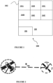
- FIG. 1 illustrates a system 100 for launching multiple satellites from a launch vehicle in accordance to the embodiment herein.
- the system 100 includes a mechanical structure 102 which has one or more mounting means 104A-F, a control unit 106 for controlling the one or more mounting means for positioning and separating the multiple satellites in the mechanical structure, an image capturing system (not shown) for monitoring the positioning of each satellite in the mechanical structure.
- the mounting means are adapted to position the satellites in axial, inclined and radial separations at a distance to ensure that each satellite will not come in contact with each other in short duration as well as long duration of orbit evolution.
- the mounting means is adapted to position one or more satellites. First set of mounting means are arranged in the axial separation and second set of mounting means are arranged in the inclined separation and third set of mounting means are arranged in the radial separation.
- the mounting configuration will have the following constraints.
- the satellites separation sequence is designed. with following mission constraints in addition to the above with respect to mounting requirement.
- separation of multiple satellites is done in a very short time span (not exceeding 1000s from terminal stage cut off) meeting the probability of collision of 1 in 100000 based on distance between any two pairs of bodies with respect to their deployed sizes. Also separated bodies are having no interaction with plume of upper stage control system.
- the mission strategy can be explained using a flow chart as shown below.
- a new method is devised to compute the distance between the satellites for any given probability of collision.
- the characteristic radius of a satellite/upper stage is the radius of sphere circumscribing it.
- the collision probability threshold for Space Object Proximity Analysis is 1 in 1000 and for Collision Avoidance (COLA) is 1 in 1,00,000 in the orbital phase.
- the collision probability threshold for COLA is conservative to account for injection uncertainties, whereas for routine SOPA and SOPA for orbit manoeuvres it is relaxed.
- the invention provides a novel solution for the separation of multiple satellites with small masses in to a circular orbit.
- the in-track component of the separation delta-v can be configured by selecting the appropriate direction of separation. For arriving at a systematic separation sequence all the satellites are separated in the orbital plane.
- the in-track delta-v components are arranged in the desired order (descending or ascending) by selecting the appropriate direction of separation in the orbital plane. For avoiding short term overtaking by the satellites, it is required to have the in-track delta v in the descending order of their magnitude.
- the satellites separating in the opposite direction will always have the time period difference between them except for the case of separation in exactly radial direction.
- we divide the satellites in two groups one separating in the velocity direction and the other separating in the anti-velocity direction and solve for sequence timing for one group of the satellites and separate other simultaneously with same timings.
- a small roll rate between 0.20 to 0.35 deg/s is used to get the desired angle for separation in the orbital plane.
- the design methodology is used for radial separations only. For axial separation, all the satellites are separated at fixed optimal attitude to meet the desired minimum distance.
- Figure 3 illustrates a flow diagram 300 for deploying and launching multiple satellites using a mechanical structure at a launching vehicle according to an example not being covered by the appended claims.
- the multiple satellites in a one or more mounting means provided in the mechanical structure are positioned, wherein the mounting means are arranged at a distance to satisfy the long term collision free requirement based on a maximum collision probability (Pmax).
- Pmax maximum collision probability
- first set of satellites in axial direction and second set of satellites in radial direction are separated from the multiple satellites.
- second set of satellites into two groups based on velocity direction and anti-velocity direction is divided.
- step 308 the satellites grouped under any one of the two groups with a small roll rate between 0.20 to 0.35 degrees to ensure separation of satellites in an orbital plane along velocity and anti-velocity directions are re-oriented and separated.
- step 310 launching the first set of satellites arranged in axial direction, part of the second set of satellites arranged in radial direction and remaining part of the second set of satellites arranged in inclined direction from the launch vehicle to separate them with appropriate in-track delta v distribution.
- the video imaging system is appropriately mounted and positioned which can capture all separation events.
- the separating step ensures that all the satellites can be separated at optimal attitude to meet the desired minimum distance for all separation.
- the re-orienting step a roll rate controllability is achieved between 0.20 to 0.35 degrees to get the desired angle and direction of separation in the orbital plane.
- the roll-rate and the timing of the separation is selected so as to achieve the direction of separation in the orbital plane to provide the desired in-track delta-v difference between the two separations to ensure that the two satellites separating do not come in contact with each other on short period as well as long period of orbit evolution.
- the separating step ensures no interaction between plume of upper stage control thruster and separating satellites.
- the satellites separation direction is finalized such that after separation they will have no possibility of entering the control system plume. Once this is finalized the proximity analysis is done to have sufficient gap between the separating satellites by adjusting the time of separation.
Landscapes
- Engineering & Computer Science (AREA)
- Remote Sensing (AREA)
- Aviation & Aerospace Engineering (AREA)
- Physics & Mathematics (AREA)
- Astronomy & Astrophysics (AREA)
- General Physics & Mathematics (AREA)
- Position Fixing By Use Of Radio Waves (AREA)
Description
- The present embodiment generally relates to a system for launching multiple satellites from a launch vehicle, and more particularly relates to a system to ensure separation of multiple satellites which is free of any plume interaction and to satisfy the long term collision free requirement.
- Conventional satellite deployment systems use multistage launch vehicles to reach an insertion orbit before they individually separate and fly to their final operational orbit. The launch vehicle has a limited amount of power and propulsion, so all satellites should be deployed within a relatively small time window. In case of large number of satellites as payloads, deploying them in relatively quick succession within the limited time window is difficult because of the close proximity and inherent risks of a potential collision between satellites.
- Prior art (www.nasaspaceflight.com) discloses the use of retro firing to move the upper stage away after detaching the satellite from the vehicle. Another prior art (
US 9463882 B1 -
US 9463882 131 discloses a system and method for assembling and deploying satellites. In this invention multiple dispenser modules are used with their own propulsion units to separate a set of satellites from the module. The modules are separated from the terminal stage of the vehicle at designated time and can be manoeuvred away from each other to avoid collision. The limitations of this invention was addressed and novel strategies in the present invention are (1) All satellites were attached at appropriate orientation and separated from the terminal stage directly (2) Providing roll manoeuvre, controlling the timing of the separation and separating the satellites at different angles simultaneously in different directions and (3) The positioning of video imaging system substantiated the clean separation. - Reference: digitalcommons.usu.edu, Proceedings of the AIAA/USU Conference on Small Satellites 2002, Donald E. Keenan, "A Deployment Strategy for Multiple Secondary Payloads on the MLV05 Mission" discloses multiple satellite separations where primary option is separation of various satellites with different relative velocities (delta-v) at different time intervals where the total separation time window was defined as 45 minutes. The limitations of this method addressed using the present invention are (1) nearly the same relative velocity for the satellites by using same separation mechanism (2) the total time of the mission can be limited below 800s.
- Reference: www.nasaspaceflight.com discloses that Russian launcher separated 37 satellites from the back of the rocket when the stage is still firing. In such a system there is a possibility that the satellites can encounter plume of the rocket propulsion system. The limitations of this method addressed using the present invention are (1) the satellites were separated in both the velocity and anti-velocity directions simultaneously (2) suitable mounting direction of satellites avoiding plume interaction (3) positioning of video imaging system captured clean separation of all satellites and ensured absence of plume interaction. Also the absence of any plume was captured by the video imaging system.
-
FR2805245A1 -
US8888050B1 describes a system and method interface one or more secondary payloads to a launch vehicle, wherein one or more circuit boards provide a secondary payload interface for each of the one or more secondary payloads. -
US4067308A describes an apparatus for spin ejecting a body having a flat plate base containing bosses, effecting the ejection with compressible cylindrical springs. The springs are compressed and when released causes a piston to spin eject a body. - To sum up, the prior arts are having many limitations. None of them provide a reliable method for deploying large number satellites in a safe, timely and cost-effective manner. In order to overcome these limitations, an innovative system and method in mission management for deployment of multiple satellites using multi stage launch vehicle is realized. The present embodiment solves one or more of these problems in a unique and economical manner.
- The novel mission management strategy for the deployment of multiple satellites is having the following objects:
The primary object of the invention is clean separation of multiple satellites. Another object of the invention is to ensure separation of multiple satellites with gap build up in the first few orbits. - Still another object of the invention is to ensure separation of multiple satellites which is free of any plume interaction.
- Yet another object of the invention is to realize a novel manoeuvring scheme of upper stage to which satellites are attached without any retro firing to move the upper stage away after detaching the satellite from the vehicle.
- Further object of the invention is to eliminate the use of any dispenser module with a propulsion unit for assisting satellite deployment.
- Still further object of the invention is to ensure that no part of the separation system used to deploy a satellite shall block the path of the satellites separating subsequently.
- Another object of the invention is to accomplish all the satellite separation within short mission duration. Still another object of the invention is to provide appropriate mounting direction for safe separation without any collision.
- Further object of the invention is to capture all separations by positioning video imaging systems at appropriate places.
- In accordance with the aforesaid objects, the present invention provides a novel system and method for deployment of multiple satellites enabling realisation of the above mentioned objects.
- In one aspect of the present embodiment a system according to claim 1 is provided. The system includes a mechanical structure which has one or more mounting means, a control unit for controlling the one or more mounting means for positioning and separating the multiple satellites in the mechanical structure, an image capturing system for monitoring the positioning of each satellite in the mechanical structure. The mounting means are adapted to position the satellites in axial, inclined and radial separations at a distance to ensure that each satellite will not come in contact with each other in short duration as well as long duration of orbit evolution. The mounting means is adapted to position one or more satellites. First set of mounting means are arranged in the axial separation and second set of mounting means are arranged in the inclined separation and third set of mounting means are arranged in the radial separation. The required minimum distance between the separated bodies when they are crossing each other distance are determined based on maximum collision probability (Pmax) which is derived from the following equation (Ref. Vladimir A. Chobotov, Orbital Mechanics, Second Edition, AIAA Educational Series, 1996):

- The advantages and features of the invention will become more clearly apparent from the following description which refers to the accompanying drawings given as non-restrictive examples only and in which:
-
Figure 1 illustrates a system for launching multiple satellites from a launch vehicle in accordance to the embodiment herein; -
Figure 2 illustrates a schematic representation showing minimum distance between two satellites in accordance to the embodiment herein; and -
Figure 3 illustrates an example not being covered by the appended claims of a flow diagram for deploying and launching multiple satellites using a mechanical structure at a launching vehicle. - The present invention will be described herein below with reference to the accompanying drawings. A system and method for launching multiple satellites from a launch vehicle is described herein.
- The following description is of exemplary embodiment of the invention only, and is not limit the scope, applicability or configuration of the invention. Rather, the following description is intended to provide a convenient illustration for implementing various embodiments of the invention. As will become apparent, various changes may be made in the function and arrangement of the structural/operational features described in these embodiments without departing from the scope of the invention as set forth herein.
- Thus the detailed description herein is presented for purposes of illustration only and not of limitation.
-
Figure 1 illustrates asystem 100 for launching multiple satellites from a launch vehicle in accordance to the embodiment herein. Thesystem 100 includes amechanical structure 102 which has one or more mounting means 104A-F, acontrol unit 106 for controlling the one or more mounting means for positioning and separating the multiple satellites in the mechanical structure, an image capturing system (not shown) for monitoring the positioning of each satellite in the mechanical structure. The mounting means are adapted to position the satellites in axial, inclined and radial separations at a distance to ensure that each satellite will not come in contact with each other in short duration as well as long duration of orbit evolution. The mounting means is adapted to position one or more satellites. First set of mounting means are arranged in the axial separation and second set of mounting means are arranged in the inclined separation and third set of mounting means are arranged in the radial separation. - The multiple satellite deployment missions pose challenges for configuring the mounting and designing the satellite separation sequence to avoid re-contact possibility as there will be a large number of bodies corresponding to satellites and spent stages. The mounting configuration will have the following constraints.
- 1. Axial separation for some satellites, inclined separation for some other satellites and also radial separations for a bunch of other satellites.
- 2. Mounting of radially separating satellites to ensure no interaction between plume of upper stage control thruster and separating satellite.
- 3. No part of the separation system used to deploy a satellite shall block the path of the satellites separating subsequently.
- The satellites separation sequence is designed. with following mission constraints in addition to the above with respect to mounting requirement.
- 1. The minimum distance between all body pairs to satisfy collision probability of 1 in 100000 and positive margin in mounting configuration.
- 2. Satellites separating from same sequencer to have minimum of 5s delay.
- 3. Minimum number of re-orientations to be used for the satellites separations.
- 4. Minimum time for all satellites separations.
- To achieve collision free long term orbital motion of the satellites, design was carried out first by analytically placing the satellites properly in spatial as well as temporal. Later the time intervals between the satellite injections were tuned by using the full force model for orbital propagations.
- In the present invention, separation of multiple satellites is done in a very short time span (not exceeding 1000s from terminal stage cut off) meeting the probability of collision of 1 in 100000 based on distance between any two pairs of bodies with respect to their deployed sizes. Also separated bodies are having no interaction with plume of upper stage control system. The mission strategy can be explained using a flow chart as shown below.

- A new method is devised to compute the distance between the satellites for any given probability of collision.
- The characteristic radius of a satellite/upper stage is the radius of sphere circumscribing it. Let r 1 and r2 be the characteristic radii of two satellites considered [Refer
fig.2 ] and Rmin be the minimum distance between them and Rs is the effective collision radius (= r 1 +r2). The maximum collision probability is given as:
- The collision probability threshold for Space Object Proximity Analysis (SOPA) is 1 in 1000 and for Collision Avoidance (COLA) is 1 in 1,00,000 in the orbital phase. The collision probability threshold for COLA is conservative to account for injection uncertainties, whereas for routine SOPA and SOPA for orbit manoeuvres it is relaxed. The invention provides a novel solution for the separation of multiple satellites with small masses in to a circular orbit.
- For satellites separating with same delta-v, the in-track component of the separation delta-v can be configured by selecting the appropriate direction of separation. For arriving at a systematic separation sequence all the satellites are separated in the orbital plane. The in-track delta-v components are arranged in the desired order (descending or ascending) by selecting the appropriate direction of separation in the orbital plane. For avoiding short term overtaking by the satellites, it is required to have the in-track delta v in the descending order of their magnitude.
- The satellites separating in the opposite direction will always have the time period difference between them except for the case of separation in exactly radial direction. Hence we divide the satellites in two groups, one separating in the velocity direction and the other separating in the anti-velocity direction and solve for sequence timing for one group of the satellites and separate other simultaneously with same timings. A small roll rate between 0.20 to 0.35 deg/s is used to get the desired angle for separation in the orbital plane. The design methodology is used for radial separations only. For axial separation, all the satellites are separated at fixed optimal attitude to meet the desired minimum distance.
-
Figure 3 illustrates a flow diagram 300 for deploying and launching multiple satellites using a mechanical structure at a launching vehicle according to an example not being covered by the appended claims. Instep 302, the multiple satellites in a one or more mounting means provided in the mechanical structure are positioned, wherein the mounting means are arranged at a distance to satisfy the long term collision free requirement based on a maximum collision probability (Pmax). Instep 304, first set of satellites in axial direction and second set of satellites in radial direction are separated from the multiple satellites. Instep 306, second set of satellites into two groups based on velocity direction and anti-velocity direction is divided. Instep 308, the satellites grouped under any one of the two groups with a small roll rate between 0.20 to 0.35 degrees to ensure separation of satellites in an orbital plane along velocity and anti-velocity directions are re-oriented and separated. Instep 310, launching the first set of satellites arranged in axial direction, part of the second set of satellites arranged in radial direction and remaining part of the second set of satellites arranged in inclined direction from the launch vehicle to separate them with appropriate in-track delta v distribution. The video imaging system is appropriately mounted and positioned which can capture all separation events. The separating step ensures that all the satellites can be separated at optimal attitude to meet the desired minimum distance for all separation. The re-orienting step a roll rate controllability is achieved between 0.20 to 0.35 degrees to get the desired angle and direction of separation in the orbital plane. The roll-rate and the timing of the separation is selected so as to achieve the direction of separation in the orbital plane to provide the desired in-track delta-v difference between the two separations to ensure that the two satellites separating do not come in contact with each other on short period as well as long period of orbit evolution. The separating step ensures no interaction between plume of upper stage control thruster and separating satellites. - The satellites separation direction is finalized such that after separation they will have no possibility of entering the control system plume. Once this is finalized the proximity analysis is done to have sufficient gap between the separating satellites by adjusting the time of separation.
- The technical advantages of the present embodiment are as follows:
- 1. Achieved axial separation of the first batch of satellites to be separated, inclined separation of the second batch of satellites to be separated and radial separation of the remaining satellites.
- 2. It is ensured that all satellite separations were completed within the short mission duration with 1 in 100000 probability of collision after stage cut-off as against the normal sequence without the manoeuvre.
- 3. Minimum time delay is ensured for the satellites separating from same sequencer.
- 4. Minimum numbers of re-orientations are used for the satellite separations.
- 5. It is ensured that all separated satellites have an ever increasing gap among themselves in the first 10 orbits.
- It is to be understood that the above description is intended to be illustrative, and not restrictive.
Claims (2)
- A system for launching multiple satellites from a launch vehicle (100) comprising:the launch vehicle (100); a mechanical structure (102) which comprises three sets of mounting means (104A-F), said mounting means adapted to position a plurality of satellites;wherein a first set of mounting means is arranged for axial separation from the launch vehicle of part of the plurality of satellites, a second set of mounting means is arranged for inclined separation from the launch vehicle of part of the plurality of satellites, and a third set of mounting means is arranged for radial separation from the launch vehicle of part of the plurality of satellites;wherein the first set of mounting means is arranged in the axial separation direction, the second set of mounting means is arranged in the inclined separation direction and the third set of mounting means is arranged in the radial separation direction; $a control unit (106) for controlling said mounting means for positioning and separating said multiple satellites in said mechanical structure;an image capturing system for monitoring the positioning of each satellite in said mechanical structure; andwherein said mounting means are adapted to position the satellites at a distance to ensure that each satellite will not come in contact with each other in short duration as well as long duration of orbit evolution.
- The system as claimed in claim 1, wherein said distance between the separation of satellites are determined based on maximum collision probability (Pmax) which is derived from the following equation:

Applications Claiming Priority (2)
| Application Number | Priority Date | Filing Date | Title |
|---|---|---|---|
| IN201841035794 | 2018-09-24 | ||
| PCT/IN2019/050344 WO2020065660A1 (en) | 2018-09-24 | 2019-04-30 | A system and method for launching multiple satellites from a launch vehicle |
Publications (3)
| Publication Number | Publication Date |
|---|---|
| EP3856644A1 EP3856644A1 (en) | 2021-08-04 |
| EP3856644A4 EP3856644A4 (en) | 2022-06-22 |
| EP3856644B1 true EP3856644B1 (en) | 2024-05-22 |
Family
ID=69952488
Family Applications (1)
| Application Number | Title | Priority Date | Filing Date |
|---|---|---|---|
| EP19865304.0A Active EP3856644B1 (en) | 2018-09-24 | 2019-04-30 | A system and method for launching multiple satellites from a launch vehicle |
Country Status (6)
| Country | Link |
|---|---|
| US (1) | US12195207B2 (en) |
| EP (1) | EP3856644B1 (en) |
| JP (1) | JP7192135B2 (en) |
| CN (1) | CN112752715B (en) |
| IL (1) | IL281696A (en) |
| WO (1) | WO2020065660A1 (en) |
Families Citing this family (5)
| Publication number | Priority date | Publication date | Assignee | Title |
|---|---|---|---|---|
| US12151833B2 (en) * | 2019-09-26 | 2024-11-26 | Mitsubishi Electric Corporation | Satellite constellation forming system, satellite constellation forming method, and ground facility |
| CN113501147B (en) * | 2021-06-08 | 2022-11-18 | 上海宇航系统工程研究所 | Connecting and separating device for spherical detector |
| CN113978764B (en) * | 2021-11-30 | 2023-07-21 | 长光卫星技术股份有限公司 | Anti-collision satellite-rocket separation method suitable for batch networking satellite orbit |
| CN117302555B (en) * | 2023-01-29 | 2026-04-10 | 西安天宇星控信息科技有限公司 | Multi-satellite real-time orbit determination method in multi-satellite launch mode |
| CN116986016B (en) * | 2023-05-22 | 2026-04-07 | 上海格思航天科技有限公司 | A Multi-Star Separation Timing Design Method |
Family Cites Families (28)
| Publication number | Priority date | Publication date | Assignee | Title |
|---|---|---|---|---|
| US4067308A (en) * | 1976-11-02 | 1978-01-10 | The United States Of America As Represented By The United States Department Of Energy | Spin ejector |
| US4455943A (en) * | 1981-08-21 | 1984-06-26 | The Boeing Company | Missile deployment apparatus |
| US5199672A (en) * | 1990-05-25 | 1993-04-06 | Orbital Sciences Corporation | Method and apparatus for deploying a satellite network |
| US5145130A (en) * | 1991-10-23 | 1992-09-08 | The United States Of America As Represented By The Administrator Of The National Aeronautics & Space Administration | Robot serviced space facility |
| RU2111901C1 (en) * | 1994-06-22 | 1998-05-27 | Научно-производственное объединение прикладной механики | Method for separation of satellites and moving apart in orbit at group launch by one rocket |
| US5611505A (en) * | 1994-11-18 | 1997-03-18 | Hughes Electronics | Spacecraft energy storage, attitude steering and momentum management system |
| US6416018B2 (en) * | 1996-09-17 | 2002-07-09 | The Boeing Company | Satellite dispenser |
| US5884866A (en) * | 1996-09-17 | 1999-03-23 | Mcdonnell Douglas Corporation | Satellite dispenser |
| US5931419A (en) * | 1997-08-07 | 1999-08-03 | Honeywell Inc. | Reducing satellite weight and cost |
| DE19856670B4 (en) * | 1998-12-09 | 2004-12-02 | Eads Space Transportation Gmbh | Satellite launching device |
| US6545601B1 (en) * | 1999-02-25 | 2003-04-08 | David A. Monroe | Ground based security surveillance system for aircraft and other commercial vehicles |
| US6296206B1 (en) * | 1999-12-01 | 2001-10-02 | The Boeing Company | Cantilever, bi-level platform satellite dispenser |
| FR2805245A1 (en) * | 2000-02-23 | 2001-08-24 | Centre Nat Etd Spatiales | METHOD FOR LAUNCHING A PLURITY OF ARTIFICIAL SATELLITES MOUNTED ON A SAME SPACE LAUNCHER AND DEVICE FOR IMPLEMENTING THIS METHOD |
| EP1257470B1 (en) * | 2000-02-23 | 2004-06-09 | Centre National D'etudes Spatiales | Method for making a support base plate for an artificial satellite on a dispenser platform for a plurality of such satellites |
| US20050127242A1 (en) * | 2000-08-08 | 2005-06-16 | Rivers Eugene P.Jr. | Payload dispensing system particularly suited for unmanned aerial vehicles |
| US6691034B1 (en) * | 2002-07-30 | 2004-02-10 | The Aerospace Corporation | Vehicular trajectory collision avoidance maneuvering method |
| JP3943066B2 (en) * | 2003-09-02 | 2007-07-11 | 川崎重工業株式会社 | Satellite separation structure and rocket |
| US7437246B2 (en) * | 2006-08-01 | 2008-10-14 | Raytheon Company | Method of determining a collision avoidance maneuver |
| US8016240B2 (en) * | 2007-03-29 | 2011-09-13 | The Boeing Company | Satellites and satellite fleet implementation methods and apparatus |
| WO2010140161A1 (en) * | 2009-06-04 | 2010-12-09 | Department Of Space, Indian Space Research Organization (Isro) | Fiber optic liquid level detector |
| JP5569150B2 (en) * | 2010-05-31 | 2014-08-13 | 株式会社Ihi | Satellite mounted system |
| US8888050B1 (en) * | 2011-02-15 | 2014-11-18 | Design—Net Engineering, LLC | Launch vehicle payload interface systems and methods |
| CN103738509A (en) * | 2014-01-21 | 2014-04-23 | 北京航空航天大学 | Novel multi-satellite separating, unlocking and releasing device |
| JP6670837B2 (en) * | 2014-08-26 | 2020-03-25 | イフェクティブ・スペース・ソリューションズ・リミテッドEffective Space Solutions Ltd | Docking system and docking method for satellite |
| US20160304219A1 (en) * | 2015-04-15 | 2016-10-20 | Space Systems/Loral, Llc | Satellite stacked launch and orbit raising optimization |
| US9463882B1 (en) * | 2015-04-30 | 2016-10-11 | Worldvu Satellites Limited | System and method for assembling and deploying satellites |
| US10351268B2 (en) * | 2016-12-08 | 2019-07-16 | The Boeing Company | Systems and methods for deploying spacecraft |
| US10538348B2 (en) * | 2016-12-19 | 2020-01-21 | Vector Launch Inc. | Triggered satellite deployment mechanism |
-
2019
- 2019-04-30 EP EP19865304.0A patent/EP3856644B1/en active Active
- 2019-04-30 US US17/279,232 patent/US12195207B2/en active Active
- 2019-04-30 JP JP2021541337A patent/JP7192135B2/en active Active
- 2019-04-30 CN CN201980062581.2A patent/CN112752715B/en active Active
- 2019-04-30 WO PCT/IN2019/050344 patent/WO2020065660A1/en not_active Ceased
-
2021
- 2021-03-21 IL IL281696A patent/IL281696A/en unknown
Also Published As
| Publication number | Publication date |
|---|---|
| EP3856644A1 (en) | 2021-08-04 |
| JP2022517417A (en) | 2022-03-08 |
| EP3856644A4 (en) | 2022-06-22 |
| US12195207B2 (en) | 2025-01-14 |
| CN112752715B (en) | 2024-08-06 |
| IL281696A (en) | 2021-05-31 |
| CN112752715A (en) | 2021-05-04 |
| WO2020065660A1 (en) | 2020-04-02 |
| JP7192135B2 (en) | 2022-12-19 |
| US20210403181A1 (en) | 2021-12-30 |
Similar Documents
| Publication | Publication Date | Title |
|---|---|---|
| US12195207B2 (en) | System and method for launching multiple satellites from a launch vehicle | |
| RU2765039C2 (en) | Servicing satellite for providing orbital services, using variable engine control | |
| EP3333086B1 (en) | Systems and methods for deploying spacecraft | |
| US20130175401A1 (en) | Salvaging and Braking Device for Objects Flying Freely in Space | |
| EP3699097B1 (en) | Systems and methods for launching a plurality of spacecraft | |
| US5626310A (en) | Space launch vehicles configured as gliders and towed to launch altitude by conventional aircraft | |
| US6921051B2 (en) | System for the delivery and orbital maintenance of micro satellites and small space-based instruments | |
| US7219858B2 (en) | Method for deploying multiple spacecraft | |
| CN107532923A (en) | System and method for assembling and disposing satellite | |
| JP7713523B2 (en) | Method and system for multi-object space debris removal - Patents.com | |
| RU2614466C2 (en) | Space transport system control method | |
| RU2817623C2 (en) | System and method for launching multiple satellites from launcher rocket | |
| US11794929B2 (en) | Method for ejecting a payload from a spacecraft driven by a continuous propulsion force | |
| Vance et al. | An Exploration of Sample and Return from Rubble Pile Asteroids via Capture of Ejected Particles | |
| Votta et al. | David the first 6u cubesat mission of the italian space agency programme iperdrone as demonstration of new on orbit services performed by space drones | |
| RU2772500C2 (en) | Serving satellite for orbital services using variable engine control | |
| Mohrdieck | Conceptual Study of Launch Abort System and Capabilities for the Nyx Earth Crew Spacecraft | |
| RU2021108797A (en) | SYSTEM AND METHOD FOR LAUNCHING MULTIPLE SATELLITES FROM BOAT ROCKET | |
| Piplica et al. | GOLauncher 1 Hypersonic Testbed | |
| JAMES | Although the official US position at that time was that we were not | |
| Ledkov et al. | Near Moon Gravity Assist Maneuvers as a Tool for Asteroid Capture onto Earth Satellite Orbit | |
| Repper | OMV payload support concept for Pegasus boosted payloads. | |
| Lindberg | Paper Session II-B-The Pegasus Air-Launched Space Booster | |
| Mennie | Military and aerospace: Dollars for many projects may be grounded, but efforts to spend wisely are soaring |
Legal Events
| Date | Code | Title | Description |
|---|---|---|---|
| STAA | Information on the status of an ep patent application or granted ep patent |
Free format text: STATUS: THE INTERNATIONAL PUBLICATION HAS BEEN MADE |
|
| PUAI | Public reference made under article 153(3) epc to a published international application that has entered the european phase |
Free format text: ORIGINAL CODE: 0009012 |
|
| STAA | Information on the status of an ep patent application or granted ep patent |
Free format text: STATUS: REQUEST FOR EXAMINATION WAS MADE |
|
| 17P | Request for examination filed |
Effective date: 20210401 |
|
| AK | Designated contracting states |
Kind code of ref document: A1 Designated state(s): AL AT BE BG CH CY CZ DE DK EE ES FI FR GB GR HR HU IE IS IT LI LT LU LV MC MK MT NL NO PL PT RO RS SE SI SK SM TR |
|
| DAV | Request for validation of the european patent (deleted) | ||
| DAX | Request for extension of the european patent (deleted) | ||
| A4 | Supplementary search report drawn up and despatched |
Effective date: 20220519 |
|
| RIC1 | Information provided on ipc code assigned before grant |
Ipc: B64G 1/00 20060101ALN20220513BHEP Ipc: B64G 1/64 20060101AFI20220513BHEP |
|
| GRAP | Despatch of communication of intention to grant a patent |
Free format text: ORIGINAL CODE: EPIDOSNIGR1 |
|
| STAA | Information on the status of an ep patent application or granted ep patent |
Free format text: STATUS: GRANT OF PATENT IS INTENDED |
|
| RIC1 | Information provided on ipc code assigned before grant |
Ipc: B64G 1/00 20060101ALN20231109BHEP Ipc: B64G 1/64 20060101AFI20231109BHEP |
|
| INTG | Intention to grant announced |
Effective date: 20231205 |
|
| GRAS | Grant fee paid |
Free format text: ORIGINAL CODE: EPIDOSNIGR3 |
|
| GRAA | (expected) grant |
Free format text: ORIGINAL CODE: 0009210 |
|
| STAA | Information on the status of an ep patent application or granted ep patent |
Free format text: STATUS: THE PATENT HAS BEEN GRANTED |
|
| AK | Designated contracting states |
Kind code of ref document: B1 Designated state(s): AL AT BE BG CH CY CZ DE DK EE ES FI FR GB GR HR HU IE IS IT LI LT LU LV MC MK MT NL NO PL PT RO RS SE SI SK SM TR |
|
| REG | Reference to a national code |
Ref country code: GB Ref legal event code: FG4D |
|
| REG | Reference to a national code |
Ref country code: CH Ref legal event code: EP |
|
| REG | Reference to a national code |
Ref country code: DE Ref legal event code: R096 Ref document number: 602019052741 Country of ref document: DE |
|
| REG | Reference to a national code |
Ref country code: IE Ref legal event code: FG4D |
|
| REG | Reference to a national code |
Ref country code: LT Ref legal event code: MG9D |
|
| REG | Reference to a national code |
Ref country code: NL Ref legal event code: MP Effective date: 20240522 |
|
| PG25 | Lapsed in a contracting state [announced via postgrant information from national office to epo] |
Ref country code: IS Free format text: LAPSE BECAUSE OF FAILURE TO SUBMIT A TRANSLATION OF THE DESCRIPTION OR TO PAY THE FEE WITHIN THE PRESCRIBED TIME-LIMIT Effective date: 20240922 |
|
| PG25 | Lapsed in a contracting state [announced via postgrant information from national office to epo] |
Ref country code: BG Free format text: LAPSE BECAUSE OF FAILURE TO SUBMIT A TRANSLATION OF THE DESCRIPTION OR TO PAY THE FEE WITHIN THE PRESCRIBED TIME-LIMIT Effective date: 20240522 |
|
| PG25 | Lapsed in a contracting state [announced via postgrant information from national office to epo] |
Ref country code: HR Free format text: LAPSE BECAUSE OF FAILURE TO SUBMIT A TRANSLATION OF THE DESCRIPTION OR TO PAY THE FEE WITHIN THE PRESCRIBED TIME-LIMIT Effective date: 20240522 Ref country code: FI Free format text: LAPSE BECAUSE OF FAILURE TO SUBMIT A TRANSLATION OF THE DESCRIPTION OR TO PAY THE FEE WITHIN THE PRESCRIBED TIME-LIMIT Effective date: 20240522 |
|
| PG25 | Lapsed in a contracting state [announced via postgrant information from national office to epo] |
Ref country code: GR Free format text: LAPSE BECAUSE OF FAILURE TO SUBMIT A TRANSLATION OF THE DESCRIPTION OR TO PAY THE FEE WITHIN THE PRESCRIBED TIME-LIMIT Effective date: 20240823 |
|
| PG25 | Lapsed in a contracting state [announced via postgrant information from national office to epo] |
Ref country code: PT Free format text: LAPSE BECAUSE OF FAILURE TO SUBMIT A TRANSLATION OF THE DESCRIPTION OR TO PAY THE FEE WITHIN THE PRESCRIBED TIME-LIMIT Effective date: 20240923 |
|
| REG | Reference to a national code |
Ref country code: AT Ref legal event code: MK05 Ref document number: 1688593 Country of ref document: AT Kind code of ref document: T Effective date: 20240522 |
|
| PG25 | Lapsed in a contracting state [announced via postgrant information from national office to epo] |
Ref country code: NL Free format text: LAPSE BECAUSE OF FAILURE TO SUBMIT A TRANSLATION OF THE DESCRIPTION OR TO PAY THE FEE WITHIN THE PRESCRIBED TIME-LIMIT Effective date: 20240522 |
|
| PG25 | Lapsed in a contracting state [announced via postgrant information from national office to epo] |
Ref country code: ES Free format text: LAPSE BECAUSE OF FAILURE TO SUBMIT A TRANSLATION OF THE DESCRIPTION OR TO PAY THE FEE WITHIN THE PRESCRIBED TIME-LIMIT Effective date: 20240522 |
|
| PG25 | Lapsed in a contracting state [announced via postgrant information from national office to epo] |
Ref country code: AT Free format text: LAPSE BECAUSE OF FAILURE TO SUBMIT A TRANSLATION OF THE DESCRIPTION OR TO PAY THE FEE WITHIN THE PRESCRIBED TIME-LIMIT Effective date: 20240522 |
|
| PG25 | Lapsed in a contracting state [announced via postgrant information from national office to epo] |
Ref country code: PL Free format text: LAPSE BECAUSE OF FAILURE TO SUBMIT A TRANSLATION OF THE DESCRIPTION OR TO PAY THE FEE WITHIN THE PRESCRIBED TIME-LIMIT Effective date: 20240522 |
|
| PG25 | Lapsed in a contracting state [announced via postgrant information from national office to epo] |
Ref country code: LV Free format text: LAPSE BECAUSE OF FAILURE TO SUBMIT A TRANSLATION OF THE DESCRIPTION OR TO PAY THE FEE WITHIN THE PRESCRIBED TIME-LIMIT Effective date: 20240522 |
|
| PG25 | Lapsed in a contracting state [announced via postgrant information from national office to epo] |
Ref country code: PT Free format text: LAPSE BECAUSE OF FAILURE TO SUBMIT A TRANSLATION OF THE DESCRIPTION OR TO PAY THE FEE WITHIN THE PRESCRIBED TIME-LIMIT Effective date: 20240923 Ref country code: PL Free format text: LAPSE BECAUSE OF FAILURE TO SUBMIT A TRANSLATION OF THE DESCRIPTION OR TO PAY THE FEE WITHIN THE PRESCRIBED TIME-LIMIT Effective date: 20240522 Ref country code: NO Free format text: LAPSE BECAUSE OF FAILURE TO SUBMIT A TRANSLATION OF THE DESCRIPTION OR TO PAY THE FEE WITHIN THE PRESCRIBED TIME-LIMIT Effective date: 20240822 Ref country code: NL Free format text: LAPSE BECAUSE OF FAILURE TO SUBMIT A TRANSLATION OF THE DESCRIPTION OR TO PAY THE FEE WITHIN THE PRESCRIBED TIME-LIMIT Effective date: 20240522 Ref country code: LV Free format text: LAPSE BECAUSE OF FAILURE TO SUBMIT A TRANSLATION OF THE DESCRIPTION OR TO PAY THE FEE WITHIN THE PRESCRIBED TIME-LIMIT Effective date: 20240522 Ref country code: IS Free format text: LAPSE BECAUSE OF FAILURE TO SUBMIT A TRANSLATION OF THE DESCRIPTION OR TO PAY THE FEE WITHIN THE PRESCRIBED TIME-LIMIT Effective date: 20240922 Ref country code: HR Free format text: LAPSE BECAUSE OF FAILURE TO SUBMIT A TRANSLATION OF THE DESCRIPTION OR TO PAY THE FEE WITHIN THE PRESCRIBED TIME-LIMIT Effective date: 20240522 Ref country code: GR Free format text: LAPSE BECAUSE OF FAILURE TO SUBMIT A TRANSLATION OF THE DESCRIPTION OR TO PAY THE FEE WITHIN THE PRESCRIBED TIME-LIMIT Effective date: 20240823 Ref country code: FI Free format text: LAPSE BECAUSE OF FAILURE TO SUBMIT A TRANSLATION OF THE DESCRIPTION OR TO PAY THE FEE WITHIN THE PRESCRIBED TIME-LIMIT Effective date: 20240522 Ref country code: ES Free format text: LAPSE BECAUSE OF FAILURE TO SUBMIT A TRANSLATION OF THE DESCRIPTION OR TO PAY THE FEE WITHIN THE PRESCRIBED TIME-LIMIT Effective date: 20240522 Ref country code: BG Free format text: LAPSE BECAUSE OF FAILURE TO SUBMIT A TRANSLATION OF THE DESCRIPTION OR TO PAY THE FEE WITHIN THE PRESCRIBED TIME-LIMIT Effective date: 20240522 Ref country code: AT Free format text: LAPSE BECAUSE OF FAILURE TO SUBMIT A TRANSLATION OF THE DESCRIPTION OR TO PAY THE FEE WITHIN THE PRESCRIBED TIME-LIMIT Effective date: 20240522 Ref country code: RS Free format text: LAPSE BECAUSE OF FAILURE TO SUBMIT A TRANSLATION OF THE DESCRIPTION OR TO PAY THE FEE WITHIN THE PRESCRIBED TIME-LIMIT Effective date: 20240822 |
|
| PG25 | Lapsed in a contracting state [announced via postgrant information from national office to epo] |
Ref country code: DK Free format text: LAPSE BECAUSE OF FAILURE TO SUBMIT A TRANSLATION OF THE DESCRIPTION OR TO PAY THE FEE WITHIN THE PRESCRIBED TIME-LIMIT Effective date: 20240522 |
|
| PG25 | Lapsed in a contracting state [announced via postgrant information from national office to epo] |
Ref country code: EE Free format text: LAPSE BECAUSE OF FAILURE TO SUBMIT A TRANSLATION OF THE DESCRIPTION OR TO PAY THE FEE WITHIN THE PRESCRIBED TIME-LIMIT Effective date: 20240522 |
|
| PG25 | Lapsed in a contracting state [announced via postgrant information from national office to epo] |
Ref country code: CZ Free format text: LAPSE BECAUSE OF FAILURE TO SUBMIT A TRANSLATION OF THE DESCRIPTION OR TO PAY THE FEE WITHIN THE PRESCRIBED TIME-LIMIT Effective date: 20240522 |
|
| PG25 | Lapsed in a contracting state [announced via postgrant information from national office to epo] |
Ref country code: SK Free format text: LAPSE BECAUSE OF FAILURE TO SUBMIT A TRANSLATION OF THE DESCRIPTION OR TO PAY THE FEE WITHIN THE PRESCRIBED TIME-LIMIT Effective date: 20240522 Ref country code: RO Free format text: LAPSE BECAUSE OF FAILURE TO SUBMIT A TRANSLATION OF THE DESCRIPTION OR TO PAY THE FEE WITHIN THE PRESCRIBED TIME-LIMIT Effective date: 20240522 |
|
| PG25 | Lapsed in a contracting state [announced via postgrant information from national office to epo] |
Ref country code: SM Free format text: LAPSE BECAUSE OF FAILURE TO SUBMIT A TRANSLATION OF THE DESCRIPTION OR TO PAY THE FEE WITHIN THE PRESCRIBED TIME-LIMIT Effective date: 20240522 |
|
| PG25 | Lapsed in a contracting state [announced via postgrant information from national office to epo] |
Ref country code: SM Free format text: LAPSE BECAUSE OF FAILURE TO SUBMIT A TRANSLATION OF THE DESCRIPTION OR TO PAY THE FEE WITHIN THE PRESCRIBED TIME-LIMIT Effective date: 20240522 Ref country code: SK Free format text: LAPSE BECAUSE OF FAILURE TO SUBMIT A TRANSLATION OF THE DESCRIPTION OR TO PAY THE FEE WITHIN THE PRESCRIBED TIME-LIMIT Effective date: 20240522 Ref country code: RO Free format text: LAPSE BECAUSE OF FAILURE TO SUBMIT A TRANSLATION OF THE DESCRIPTION OR TO PAY THE FEE WITHIN THE PRESCRIBED TIME-LIMIT Effective date: 20240522 Ref country code: EE Free format text: LAPSE BECAUSE OF FAILURE TO SUBMIT A TRANSLATION OF THE DESCRIPTION OR TO PAY THE FEE WITHIN THE PRESCRIBED TIME-LIMIT Effective date: 20240522 Ref country code: DK Free format text: LAPSE BECAUSE OF FAILURE TO SUBMIT A TRANSLATION OF THE DESCRIPTION OR TO PAY THE FEE WITHIN THE PRESCRIBED TIME-LIMIT Effective date: 20240522 Ref country code: CZ Free format text: LAPSE BECAUSE OF FAILURE TO SUBMIT A TRANSLATION OF THE DESCRIPTION OR TO PAY THE FEE WITHIN THE PRESCRIBED TIME-LIMIT Effective date: 20240522 |
|
| PG25 | Lapsed in a contracting state [announced via postgrant information from national office to epo] |
Ref country code: IT Free format text: LAPSE BECAUSE OF FAILURE TO SUBMIT A TRANSLATION OF THE DESCRIPTION OR TO PAY THE FEE WITHIN THE PRESCRIBED TIME-LIMIT Effective date: 20240522 |
|
| REG | Reference to a national code |
Ref country code: DE Ref legal event code: R097 Ref document number: 602019052741 Country of ref document: DE |
|
| PLBE | No opposition filed within time limit |
Free format text: ORIGINAL CODE: 0009261 |
|
| STAA | Information on the status of an ep patent application or granted ep patent |
Free format text: STATUS: NO OPPOSITION FILED WITHIN TIME LIMIT |
|
| PG25 | Lapsed in a contracting state [announced via postgrant information from national office to epo] |
Ref country code: SI Free format text: LAPSE BECAUSE OF FAILURE TO SUBMIT A TRANSLATION OF THE DESCRIPTION OR TO PAY THE FEE WITHIN THE PRESCRIBED TIME-LIMIT Effective date: 20240522 |
|
| 26N | No opposition filed |
Effective date: 20250225 |
|
| PGFP | Annual fee paid to national office [announced via postgrant information from national office to epo] |
Ref country code: LU Payment date: 20250426 Year of fee payment: 7 |
|
| PGFP | Annual fee paid to national office [announced via postgrant information from national office to epo] |
Ref country code: MC Payment date: 20250425 Year of fee payment: 7 |
|
| PGFP | Annual fee paid to national office [announced via postgrant information from national office to epo] |
Ref country code: DE Payment date: 20250430 Year of fee payment: 7 |
|
| PGFP | Annual fee paid to national office [announced via postgrant information from national office to epo] |
Ref country code: GB Payment date: 20250426 Year of fee payment: 7 |
|
| PGFP | Annual fee paid to national office [announced via postgrant information from national office to epo] |
Ref country code: BE Payment date: 20250426 Year of fee payment: 7 |
|
| PGFP | Annual fee paid to national office [announced via postgrant information from national office to epo] |
Ref country code: FR Payment date: 20250428 Year of fee payment: 7 |
|
| PGFP | Annual fee paid to national office [announced via postgrant information from national office to epo] |
Ref country code: CH Payment date: 20250501 Year of fee payment: 7 |
|
| PGFP | Annual fee paid to national office [announced via postgrant information from national office to epo] |
Ref country code: IE Payment date: 20250424 Year of fee payment: 7 |
|
| PG25 | Lapsed in a contracting state [announced via postgrant information from national office to epo] |
Ref country code: SE Free format text: LAPSE BECAUSE OF FAILURE TO SUBMIT A TRANSLATION OF THE DESCRIPTION OR TO PAY THE FEE WITHIN THE PRESCRIBED TIME-LIMIT Effective date: 20240522 |