EP3855863A1 - System and method for 4g automatic link establishment protocol enhancement - Google Patents
System and method for 4g automatic link establishment protocol enhancement Download PDFInfo
- Publication number
- EP3855863A1 EP3855863A1 EP21153282.5A EP21153282A EP3855863A1 EP 3855863 A1 EP3855863 A1 EP 3855863A1 EP 21153282 A EP21153282 A EP 21153282A EP 3855863 A1 EP3855863 A1 EP 3855863A1
- Authority
- EP
- European Patent Office
- Prior art keywords
- pdu
- snr value
- called
- calling
- snr
- Prior art date
- Legal status (The legal status is an assumption and is not a legal conclusion. Google has not performed a legal analysis and makes no representation as to the accuracy of the status listed.)
- Granted
Links
Images



Classifications
-
- H—ELECTRICITY
- H04—ELECTRIC COMMUNICATION TECHNIQUE
- H04W—WIRELESS COMMUNICATION NETWORKS
- H04W76/00—Connection management
- H04W76/10—Connection setup
- H04W76/14—Direct-mode setup
-
- H—ELECTRICITY
- H04—ELECTRIC COMMUNICATION TECHNIQUE
- H04L—TRANSMISSION OF DIGITAL INFORMATION, e.g. TELEGRAPHIC COMMUNICATION
- H04L45/00—Routing or path finding of packets in data switching networks
- H04L45/74—Address processing for routing
- H04L45/745—Address table lookup; Address filtering
-
- H—ELECTRICITY
- H04—ELECTRIC COMMUNICATION TECHNIQUE
- H04W—WIRELESS COMMUNICATION NETWORKS
- H04W76/00—Connection management
- H04W76/10—Connection setup
Definitions
- ALE Automatic Link Establishment
- a link quality for data communication between HF radios may be determined, at least in part, on a call linking time and a selected data rate.
- the call linking time may be determined by a length of an air frame during a three-way ALE handshake.
- the selected data rate may be determined by a signal-to-noise ratio (SNR) received during the ALE handshake.
- SNR signal-to-noise ratio
- a method for 4G Automatic Link Establishment protocol enhancement is disclosed, in accordance with one or more embodiments of the disclosure.
- the method may include, but is not limited to, receiving a first protocol data unit (PDU) including a first number of transmit level control (TLC) blocks for an Automatic Link Establishment (ALE) handshake from a calling participating unit (calling PU).
- the first PDU may lead to a first signal-to-noise ratio (SNR) value being determined by a called participating unit (called PU).
- SNR signal-to-noise ratio
- the method may include, but is not limited to, determining a second SNR value corresponding to the first SNR value of the first PDU from a stored lookup table of the called PU.
- the method may include, but is not limited to, transmitting a second PDU including the second number of TLC blocks for the ALE handshake to the calling PU following the receipt of the first PDU.
- the second PDU may lead to a third SNR value being determined by the calling PU.
- the method may include, but is not limited to, receiving a third PDU including a third number of TLC blocks for the ALE handshake from the calling PU following the transmission of the second PDU.
- the third PDU may include a fourth SNR value.
- the third PDU may lead to a fifth SNR value being determined by the called PU.
- a call linking time with the calling PU may be dependent on at least one of the first number of TLC blocks in the first PDU, the second number of TLC blocks in the second PDU, or the third number of TLC blocks in the third PDU.
- the call linking time may be reduced with at least one of a low number of TLC blocks for the first number of TLC blocks in the first PDU, a low number of TLC blocks for the second number of TLC blocks in the second PDU, or a low number of TLC blocks for the third number of TLC blocks in the third PDU.
- a data transfer rate with the calling PU may be dependent on at least one of the second SNR value in an SNR field of the second PDU or the fourth SNR value in an SNR field of the third PDU.
- the call linking time may be reduced with a low number of TLC blocks for the second number of TLC blocks in the second PDU.
- the call linking time may be reduced with a low number of TLC blocks for the third number of TLC blocks in the third PDU.
- the method may include, but is not limited to, acquiring the lookup table.
- the lookup table may be prepopulated.
- the lookup table may be prepopulated with simulated data.
- the lookup table may be generated from over-the-air measurements.
- the method may include, but is not limited to, applying a scaling factor when determining the second SNR value corresponding to the first SNR value of the first PDU.
- the method may include, but is not limited to, transmitting the first PDU including the first number of TLC blocks for the ALE handshake to a called participating unit (PU).
- the first PDU may lead to the first signal-to-noise ratio (SNR) value being determined by the called PU.
- the method may include, but is not limited to, receiving the second PDU including the second number of TLC blocks for the ALE handshake from the called PU following the transmission of the first PDU.
- the second PDU may include the second SNR value.
- the second PDU may lead to the third SNR value being determined by the calling PU.
- the method may include, but is not limited to, determining the fourth SNR value corresponding to the third SNR value of the second PDU from a stored lookup table of the calling PU.
- the method may include, but is not limited to, transmitting the third PDU including the third number of TLC blocks for the ALE handshake to the called PU following the receipt of the second PDU.
- the third PDU may include the fourth SNR value.
- the third PDU may lead to the fifth SNR value being determined by the called PU.
- the method may include, but is not limited to, applying a scaling factor when determining the fourth SNR value corresponding to the third SNR value of the second PDU from the stored lookup table of the calling PU.
- a method for 4G Automatic Link Establishment protocol enhancement is disclosed, in accordance with one or more embodiments of the disclosure.
- the method may include, but is not limited to, transmitting a first protocol data unit (PDU) including a first number of transmit level control (TLC) blocks for an Automatic Link Establishment (ALE) handshake to a called participating unit (PU).
- the first PDU may lead to a first signal-to-noise ratio (SNR) value being determined by the called PU.
- the method may include, but is not limited to, receiving a second PDU including a second number of TLC blocks for the ALE handshake from the called PU following the transmission of the first PDU.
- the second PDU may include the second SNR value.
- the second PDU may lead to a third SNR value being determined by a calling PU.
- the method may include, but is not limited to, determining a fourth SNR value corresponding to the third SNR value of the second PDU from a stored lookup table of the calling PU.
- the method may include, but is not limited to, transmitting a third PDU including the third number of TLC blocks for the ALE handshake to the called PU following the receipt of the second PDU.
- the third PDU may include the fourth SNR value.
- the third PDU may lead to a fifth SNR value being determined by the called PU.
- the method may include, but is not limited to, receiving the first PDU including the first number of TLC blocks for the ALE handshake from a calling PU.
- the first SNR value may be determined by the called PU.
- the method may include, but is not limited to, determining the second SNR value corresponding to the first SNR value of the first PDU from a stored lookup table of the called PU.
- the method may include, but is not limited to, transmitting the second PDU including the second number of TLC blocks for the ALE handshake to the calling PU following the receipt of the first PDU.
- the second PDU may lead to the third SNR value being determined by the calling PU.
- the method may include, but is not limited to, receiving the third PDU including the third number of TLC blocks for the ALE handshake from the calling PU following the transmission of the second PDU.
- the third PDU may include the fourth SNR value.
- the third PDU may lead to the fifth SNR value being determined by the called PU.
- a letter following a reference numeral is intended to reference an embodiment of the feature or element that may be similar, but not necessarily identical, to a previously described element or feature bearing the same reference numeral (e.g., 1, 1a, 1b).
- reference numeral e.g. 1, 1a, 1b
- Such shorthand notations are used for purposes of convenience only and should not be construed to limit the disclosure in any way unless expressly stated to the contrary.
- any reference to “one embodiment” or “some embodiments” means that a particular element, feature, structure, or characteristic described in connection with the embodiment is included in at least one embodiment disclosed herein.
- the appearances of the phrase “in some embodiments” in various places in the specification are not necessarily all referring to the same embodiment, and embodiments may include one or more of the features expressly described or inherently present herein, or any combination of sub-combination of two or more such features, along with any other features which may not necessarily be expressly described or inherently present in the instant disclosure.
- FIGS. 1-7 generally illustrate a system and method for 4G Automatic Link Establishment protocol enhancement, in accordance with one or more embodiments of the disclosure.
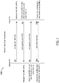
- FIG. 1 illustrates a typical three-way (or three-leg) ALE handshake 100, in accordance with one or more embodiments of the disclosure.
- a Calling Participating Unit may determine whether an ALE channel to a Called Participating Unit (Called PU) is available to receive data. If it determines the ALE channel is unoccupied, the Calling PU may send a Link Setup Request (LSU_Req) protocol data unit (PDU) (e.g., LSU_Req PDU) to a Called PU.
- LSU_Req PDU may define the Calling PU and the Called PU, an available spectrum for the channel and sub-channels, the Equipment Capability (EC) of the Calling PU, and/or the type of data to be transferred.
- the Called PU may evaluate the assigned frequency band of the transmission channel (e.g., by measuring the signal-to-noise ratio (SNR) of the assigned frequency band) with the receipt of the LSU_Req PDU (e.g., SNR1).
- the SNR1 measured in the LSU_Req PDU may be entered as func(SNR1) in an SNR field of a Link Setup Confirm (LSU_Conf) protocol data unit (PDU) (e.g., LSU_Conf_1 PDU).
- LSU_Conf Link Setup Confirm protocol data unit
- the Called PU may determine whether an ALE channel to the Calling PU is available to receive data. If it determines the ALE channel is unoccupied, the Called PU may send the LSU_Conf PDU (e.g., LSU_Conf_1 PDU).
- the LSU_Conf PDU may include the Equipment Capability (EC) of the Called PU, transmission and receiving sub-channel vectors, and the SNR1 measured in the LSU_Req PDU.
- the Calling PU may evaluate the assigned frequency band of the transmission channel (e.g., by measuring the signal-to-noise ratio (SNR) of the assigned frequency band) with the receipt of the LSU_Conf_1 PDU (e.g., SNR2).
- the SNR2 measured in the LSU_Conf_1 PDU may be entered as func(SNR2) in an SNR field of a second LSU_Conf PDU (e.g., LSU_Conf_2 PDU).
- the Calling PU may send the second LSU_Conf PDU (e.g., the LSU_Conf_2 PDU).
- the LSU_Conf_2 PDU may include the Equipment Capability (EC) of the Called PU, transmission and receiving sub-channel vectors, and the SNR2 measured in the LSU_Conf_1 PDU.
- EC Equipment Capability
- user data may be transferred from the Calling PU to the Called PU with a sending data rate based on func(SNR1).
- user data may be transferred from the Called PU to the Calling PU with a sending data rate based on func(SNR2).
- the PU not receiving the timely response may transmit an LSU_Termination (LSU_Term) PDU to terminate the link.
- LSU_Term LSU_Termination
- a link quality for data communication between HF radios may be determined, at least in part, on a call linking time and a selected data rate.
- balancing the call linking time and the selected data rate may include reducing the call linking time and selecting the highest data rate that may be supported by a HF link for data transfer after a call is linked.
- the call linking time may be determined by a length of an air frame during the three-way ALE handshake 100.
- FIG. 2 illustrates an example air frame 200, in accordance with one or more embodiments of the disclosure.
- the air frame 200 may be defined by two or three blocks, the blocks including an optional, variable Transmit Level Control (TLC) portion 202 including one or more blocks (or zero blocks, where the air frame 200 does not include the TLC portion), a fixed Preamble portion 204, and a fixed Data portion 206.
- TLC Transmit Level Control
- a shorter TLC portion 202 including a fewer number of blocks may result in a faster call linking time, while a longer TLC block 202 including a greater number of blocks may result in a better representation of call link quality and an increased call linking delay.
- the selected data rate may be determined by a signal-to-noise ratio (SNR) received during the ALE handshake.
- SNR signal-to-noise ratio
- dB decibel
- a 30 dB SNR may be considered an acceptable value for supporting data rate during data transfer
- a 50 dB SNR may be considered a great value for supporting data rate during data transfer.
- FIG. 3 illustrates a table 300 illustrating a comparison between a number of TLC blocks 302 (with corresponding call linking delay in milliseconds (ms)) and a resultant SNR value 304 (in dB) over an Additive White Gaussian Noise (AWGN) channel, in accordance with one or more embodiments of the disclosure.
- ms milliseconds
- AWGN Additive White Gaussian Noise
- an increased number of TLC blocks 302 may generally result in an increased SNR value 304.
- increasing the number of TLC blocks 302 may increase the data transfer rate, while also increasing the call linking delay.
- TLC blocks 302 are used in transmission for stabilizing Automatic Level Control (ALC) loops and Automatic Gain Control (AGC) loops, at the expense of call linking delay.
- ALC Automatic Level Control
- AGC Automatic Gain Control
- a small number of TLC blocks e.g., three blocks
- ALE Automatic Gain Control
- a large number of TLC blocks 302 may be necessary to determine an SNR performance, which may result in an increased ALE call linking time.
- ALE is a military standard described in MIL-STD-188-141D, titled Interoperability and Performance Standards for Medium and High Frequency Radio Systems, issued on December 22, 2017 . Therefore, aspects of this invention may be configured to and/or required to conform with the guidelines set forth by MIL-STD-188-141D.
- FIG. 4 illustrates an environment 400, in accordance with one or more embodiments of the disclosure.
- the environment 400 may include one or more aircraft 402, where each of the one or more aircraft 402 may include a radio 404.
- a first aircraft 402 may transmit data 406 to a second aircraft 402
- the second aircraft 402 may transmit data 408 to the first aircraft 402.
- the data transmission may follow a three-way handshake (e.g., as described with respect to FIG. 1 ).
- embodiments of the present disclosure illustrate communication occurring between two aircraft 402, it is noted herein the communication may occur between any number of aircraft 402, either in parallel or in series (e.g., chained communication). Therefore, the above description should not be interpreted as a limitation on the present disclosure but merely an illustration.
- the system and method for 4G Automatic Link Establishment protocol enhancement may be configured in accordance with aviation guidelines and/or standards put forth by, but not limited to, the Department of Defense (DoD), the Federal Aviation Administration (FAA), the European Aviation Safety Agency (EASA) or any other flight certification agency or organization; the American National Standards Institute (ANSI), Aeronautical Radio, Incorporated (ARINC), or any other standards setting organization or company; the Radio Technical Commission for Aeronautics (RTCA) or any other guidelines agency or organization; or the like.
- DoD Department of Defense
- FAA Federal Aviation Administration
- EASA European Aviation Safety Agency
- ARINC Aeronautical Radio, Incorporated
- RTCA Radio Technical Commission for Aeronautics
- the system and method for 4G Automatic Link Establishment protocol enhancement may be configured to operate in any type of vehicle known in the art.
- the vehicle may be any air, space, land, or water-based personal equipment or vehicle; any air, space, land, or water-based commercial equipment or vehicle; any air, space, land, or water-based military equipment or vehicle known in the art. Therefore, the above description should not be interpreted as a limitation on the present disclosure but merely an illustration.
- embodiments of the present disclosure are directed to a system and method for 4G Automatic Link Establishment protocol enhancement being used with radios 404 installed within aircraft 402, it is noted herein the system and method for 4G Automatic Link Establishment protocol enhancement may be coupled to and/or configured to operate with any type of radio.
- the system and method for 4G Automatic Link Establishment protocol enhancement may be implemented by one or more unmanned aerial vehicle (UAV) control stations.
- UAV unmanned aerial vehicle
- the UAV control station may be a standalone portable device. It is noted herein, however, that the UAV control station may be housed within and/or coupled to a facility or a moving vehicle (e.g., van, truck, boat, spacecraft, other aircraft, or the like).
- a moving vehicle e.g., van, truck, boat, spacecraft, other aircraft, or the like.
- the UAV control station may be subject to the avionics guidelines and/or standards as set forth above. Therefore, the above description should not be interpreted as a limitation on the present disclosure but merely an illustration.
- communication may occur between the aircraft 402 and a base station 410 (e.g., which may include a radio 404), with transmission of data 406, 408 between the aircraft 402 and the base station 410.
- a base station 410 e.g., which may include a radio 404
- communication may occur between the aircraft 402 and a satellite 412 (e.g., which may include a radio 404), with transmission of data 406, 408 between the aircraft 402 and the satellite 412.
- system and method for 4G Automatic Link Establishment protocol enhancement may be coupled to and/or configured to operate in a commercial or industrial environment (e.g., in either a home or a business). Therefore, the above description should not be interpreted as a limitation on the present disclosure but merely an illustration.
- transmission and receipt of data within the environment 400 is not limited to the directions of the data 406, 408 as illustrated in FIG. 4 .
- the data 406, 408 may be transmitted to and/or received by any device or structure within the environment 400. Therefore, the above description should not be interpreted as a limitation on the present disclosure but merely an illustration.
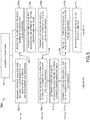
- FIG. 5 illustrates a method or process 500 for 4G Automatic Link Establishment protocol enhancement, in accordance with one or more embodiments of the disclosure.
- FIG. 6 illustrates a lookup table 600, in accordance with one or more embodiments of the present disclosure.
- a lookup table is acquired.
- the lookup table may include data for transmit level control (TLC) block number and corresponding signal-to-noise ratio (SNR).
- TLC transmit level control
- SNR signal-to-noise ratio
- the lookup table may be prepopulated for one or more link profiles
- the lookup table may be generated via one or more over-the-air measurements and stored within the radio 404 (e.g., within a radio 404 of the Calling PU (e.g., including, but not limited to, a first aircraft 402) and/or within a radio 404 of the Called PU (e.g., including, but not limited to, a second aircraft 402)).
- a link profile column 602 a list of SNR values for a select number of TLC blocks is provided.
- a link profile may be defined by a particular number of TLC blocks, a station, a frequency, a time of day, or other values/variables/metrics.
- the lookup table 600 may include multiple link profile columns representing typical high frequency (HF) link profiles including, but not limited to, Comite Consultatif International des Radiocommunications (CCIR) Poor, CCIR Good, or the like.
- the link profile column 602 may include SNR values defined for a small number of TLC blocks (e.g., 3 TLC blocks), the small number of blocks selected so as to increase the speed of ALE call linking in the ALE handshake.
- a list of SNR values for a particular number of TLC blocks (e.g., 20 TLC blocks) is provided.
- the mapped column 604 may include SNR values defined for a large number of TLC blocks (e.g., 20 TLC blocks) so as to determine a high data rate call link quality. It is noted herein the mapped column 604 may include SNR values defined for a greater number of TLC blocks than the number of TLC blocks represented in the link profile column 602.
- the alignment of the link profile column 602 and the mapped column 604 may allow for the corresponding of values within the link profile column 602 and values within the mapped column 604 (e.g., 2 with 10, 12 with 20, and the like, as illustrated in FIG. 6 ).
- the lookup table 600 may include multiple corresponding link profile columns 602 that may correspond to the mapped column 604. In addition, it is noted herein the lookup table 600 may include multiple mapped columns 604. Further, it is noted herein the lookup table 600 may be one of multiple lookup tables 600. Therefore, the above description should not be interpreted as a limitation on the present disclosure but merely an illustration.
- one or more of the link profile column 602, the mapped column 604, and/or the lookup table 600 may be determined by a modem dynamically. For example, which link profile column 602, mapped column 604, and/or lookup table 600 may be determined by a user through a selection of an operation parameter. By way of another example, the link profile column 602, the mapped column 604, and/or the lookup table 600 may be updated with new offline simulations/simulated data and/or with on-the-fly measurement calculations. Therefore, the above description should not be interpreted as a limitation on the present disclosure but merely an illustration.
- a protocol data unit (PDU) including a select number of TLC blocks for an Automatic Link Establishment (ALE) handshake is transmitted.
- a protocol data unit (PDU) including a select number of TLC blocks for an Automatic Link Establishment (ALE) handshake is received.
- the PDU may include a Link Setup Request (LSU_Req) PDU.
- LSU_Req Link Setup Request
- the select number of TLC blocks may correspond to a particular link profile column 602 of the lookup table 600.
- a first SNR value of the received PDU is determined, and a second SNR value corresponding to the first SNR value is determined.
- the first PDU may lead to the first SNR value.
- the first SNR value may be decoded from the LSU_Req PDU.
- the second SNR value corresponding to the first SNR value of the first PDU i.e., the LSU_Req PDU
- the second SNR value may be located within the mapped column 604 of the lookup table 600.
- the second SNR value may be interpolated or extrapolated before being located within the mapped column 604.
- a received 3 TLC-block signal with a 12 dB SNR may correspond to a 20 TLC-block signal with a 20 dB SNR, per the lookup table 600.
- a 3 TLC-block signal may be transmitted to the Called PU where a 12 dB SNR is measured for the first SNR value (e.g., the radio 404 of the second aircraft 402) to reduce the call linking time, and a 20 dB SNR value (that is equivalent to a 20-TLC block signal) may be entered into an SNR field of the second PDU as the second SNR value sent back to the Calling PU (e.g., the radio 404 of the first aircraft 402) to increase the data link quality of the linked call.
- the first SNR value e.g., the radio 404 of the second aircraft 402
- steps 504a, 504b may be considered a first (1st) leg of the process 500.
- steps 504a, 504b, 506 may be considered the first leg of the process 500. Therefore, the above description should not be interpreted as a limitation on the scope of the disclosure but merely an illustration.
- a protocol data unit (PDU) including a select number of TLC blocks for an Automatic Link Establishment (ALE) handshake is transmitted.
- a protocol data unit (PDU) including a select number of TLC blocks for an Automatic Link Establishment (ALE) handshake is received.
- the PDU may include a Link Setup Confirm (LSU_Conf) PDU (e.g., LSU_Conf_1 PDU).
- LSU_Conf Link Setup Confirm
- the second SNR value may be stored in an SNR field of the LSU_Conf_1 PDU.
- the select number of TLC blocks may correspond to the link profile column 602 of the lookup table 600.
- a third SNR value of the received second PDU is determined, and a fourth SNR value corresponding to the third SNR value is determined.
- the second PDU may lead to the third SNR value.
- the third SNR value may be decoded from the LSU_Conf_1 PDU.
- the fourth SNR value corresponding to the third SNR value of the received second PDU may be located within the mapped column 604 of the lookup table 600.
- the fourth SNR value may be interpolated or extrapolated before being located within the mapped column 604.
- steps 508a, 508b may be considered a second (2nd) leg of the process 500.
- steps 508a, 508b, 510 may be considered the second leg of the process 500. Therefore, the above description should not be interpreted as a limitation on the scope of the disclosure but merely an illustration.
- a protocol data unit (PDU) including a select number of TLC blocks for an Automatic Link Establishment (ALE) handshake is transmitted.
- a protocol data unit (PDU) including a select number of TLC blocks for an Automatic Link Establishment (ALE) handshake is received.
- the PDU may include a Link Setup Confirm (LSU_Conf) PDU (e.g., an LSU_Conf_2 PDU).
- LSU_Conf Link Setup Confirm
- the fourth SNR value may be stored in an SNR field of the LSU_Conf_2 PDU.
- the select number of TLC blocks may correspond to the mapped column 604 of the lookup table 600.
- a fifth SNR value of the received third PDU is determined.
- the third PDU may lead to the fifth SNR value.
- the fifth SNR value may be decoded from the LSU_Conf_2 PDU.
- steps 512a, 512b may be considered a third (3rd) leg of the process 500.
- steps 512a, 512b, 514 may be considered the third leg of the process 500. Therefore, the above description should not be interpreted as a limitation on the scope of the disclosure but merely an illustration.
- the Calling PU radio 404 and the Called PU radio 404 may successfully negotiate a call data rate.
- the first SNR value may be measured by decoding the first PDU at the Called PU, and the second SNR value may be obtained based on the decoded first SNR value via the lookup table 600 at the Called PU.
- the third SNR value may be measured by decoding the second PDU at the Calling PDU, and the fourth SNR value may be obtained based on the decoded third SNR value via the lookup table 600 at the Calling PU.
- the fifth SNR value may be measured by decoding the third PDU at the Called PU.
- the process to negotiate the call data rate may be considerably shortened with the use of the lookup table 600 and the reduced call linking time caused by the use of a smaller number of TLC blocks used within the LSU_Req PDU prior to the determination of the SNR value included in the LSU_Conf_1 PDU.
- the select number of TLC blocks used in the first leg, the second leg, and the third leg of the process 500 may be the same.
- 3 TLC blocks may be used in the first leg, the second leg, and the third leg.
- the process 500 may use the same low number of TLC blocks in the first leg, the second leg, and the third leg.
- the process 500 may use a different select number of TLC blocks in the first leg, the second leg, and/or the third leg. Therefore, the above description should not be interpreted as a limitation on the scope of the disclosure but merely an illustration.
- the process 500 is not limited to the steps and/or sub-steps provided.
- the process 500 may include more or fewer steps and/or sub-steps.
- the process 500 may perform the steps and/or sub-steps simultaneously.
- the process 500 may perform the steps and/or sub-steps sequentially, including in the order provided or an order other than provided. Therefore, the above description should not be interpreted as a limitation on the scope of the disclosure but merely an illustration.
- a scaling factor may be applied when determining the second SNR value corresponding to the first SNR value of the first PDU (e.g., from the stored lookup table 600 of the called PU).
- a scaling factor may be applied when determining the fourth SNR value corresponding to the third SNR value of the second PDU (e.g., from the stored lookup table 600 of the calling PU).
- a scaling factor may be applied with a value between 0 and 1, where 0 means "disabled” and 1 means “enabled.”
- a value between 0 and 1 may partially activate the process 500 when determining a corresponding SNR value from the stored lookup table. For example, a 2 dB SNR may scale to 10 dB SNR at 100%, or scaling factor equals "1", while a 2 dB SNR may scale to 6 dB SNR at 50%.
- the duration of an actual over-the air data transmission may be shortened without incurring any additional delay in ALE call linking time once a call is linked.
- the determined call rate may be fixed for data transfer of a small amount of data where the transmission is within a coherence time period, but that renegotiating the data rate may be necessary for larger amounts of data.
- the same process 500 using the lookup table 600 may employ the data rate renegotiation delay and determine the highest possible data rate.
- a SNR value received from a control radio 404 may be transmitted back to the control radio within the third PDU or LSU_Conf_2 value, the control radio 404 being co-located with a radio 404 under test that is using the process 500. If the control radio 404 does not return the same SNR value within its own third PDU or LSU_Conf_2 value, then the control radio 404 is performing the process 500, similar to the radio 404 under test.
- the three-way ALE handshake in FIG. 1 may be accomplished by setting the second SNR value equal to the first SNR value, and setting the fourth SNR value equal to the third SNR value, during the process 500.
- the ALC loops and AGC loops may be set manually rather than automatically by predicting a received signal strength indicator (RSSI) value, though the process of doing so may be tedious and/or difficult as compared to the generation and use of the lookup table.
- RSSI received signal strength indicator
- call linking time and traffic throughout for an ALE linked call may be optimized.
- the optimization of data rate may allow for determining a data rate that both radios 404 may work with, based on issues in the surrounding environment including, but not limited to, SNR.
- the optimization of time may allow for faster data transfer and/or a greater amount of data transfer before signal fading requiring data rate renegotiation may occur.
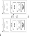
- FIG. 7 illustrates a block diagram of at least a portion of the environment 400, in accordance with one or more embodiments of the disclosure.
- the environment 400 may include the one or more radios 404.
- the one or more radios 404 may transmit data 406, 408.
- the one or more radios 404 may include one or more controllers 700.
- the one or more controllers 700 may include one or more processors 702 and memory 704.
- the memory 704 may store one or more sets of program instructions 706.
- the one or more processors 702 may be configured to execute the one or more sets of program instructions 706 to carry out one or more of the various steps described throughout the present disclosure.
- the memory 704 may include one or more tools 708 for analyzing one or more sets of data processing.
- the one or more sets of data processing may include the lookup table 600.
- the one or more sets of data processing may include a prepopulated lookup table 600.
- the one or more sets of data processing may include a lookup table 600 generated via one or more over-the-air measurements.
- the one or more controllers 700 may include one or more communication interfaces 710.
- the one or more controllers 700 may include one or more user interfaces 712.
- the one or more user interfaces 712 may include one or more display devices 714.
- the one or more user interfaces 712 may include one or more user input devices 716.
- embodiments of the present disclosure illustrate the one or more controllers 700 and the one or more user interfaces 712 being separate, it is noted herein the one or more controllers 700 and the one or more user interfaces 712 may be housed in a common housing. Therefore, the above description should not be interpreted as a limitation on the present disclosure but merely an illustration.
- the one or more processors 702 may include any one or more processing elements known in the art. In this sense, the one or more processors 702 may include any microprocessor device configured to execute algorithms and/or program instructions. In general, the term "processor" may be broadly defined to encompass any device having one or more processing elements, which execute a set of program instructions from a non-transitory memory medium (e.g., the memory 704), where the one or more sets of program instructions 706 are configured to cause the one or more processors 702 to carry out any of one or more process steps.
- a non-transitory memory medium e.g., the memory 704
- the memory 704 may include any storage medium known in the art suitable for storing the one or more sets of program instructions 706 executable by the associated one or more processors 702.
- the memory 704 may include a non-transitory memory medium.
- the memory 704 may include, but is not limited to, a read-only memory (ROM), a random access memory (RAM), a magnetic or optical memory device (e.g., disk), a magnetic tape, a solid state drive, and the like.
- the memory 704 may be configured to provide display information to the one or more display devices 714.
- the memory 704 may be configured to store user input information from the one or more user input devices 716.
- the memory 704 may be housed in a common controller housing with the one or more processors 702.
- the memory 704 may, alternatively or in addition, be located remotely with respect to the spatial location of the processors 702, the one or more controllers 700 and/or the one or more controllers 700.
- the one or more processors 702, the one or more controllers 700, and/or the one or more controllers 700 may access a remote memory 704 (e.g., server), accessible through a network (e.g., internet, intranet, and the like) via one or more communication interfaces.
- a remote memory 704 e.g., server
- a network e.g., internet, intranet, and the like
- the one or more communication interfaces 710 may be operatively configured to communicate with one or more components of the one or more controllers 700 and/or the one or more components of the one or more controllers 700.
- the one or more communication interfaces 710 may also be coupled (e.g., physically, electrically, and/or communicatively) with the one or more processors 702 to facilitate data transfer between components of the one or more components of the one or more controllers 700 and/or the one or more components of the one or more controllers 700 and the one or more processors 702.
- the one or more communication interfaces 710 may be configured to retrieve data from the one or more processors 702, or other devices, transmit data for storage in the memory 704, retrieve data from storage in the memory 704, or the like.
- the one or more controllers 700 and/or one or more offboard controllers may be configured to receive and/or acquire data or information from other systems or tools by a transmission medium that may include wireline and/or wireless portions.
- the one or more controllers 700 and/or the one or more offboard controllers may be configured to transmit data or information (e.g., the output of one or more procedures of the inventive concepts disclosed herein) to one or more systems or tools by a transmission medium that may include wireline and/or wireless portions (e.g., a transmitter, receiver, transceiver, physical connection interface, or any combination).
- the transmission medium may serve as a data link between the one or more controllers 700 and/or the one or more offboard controllers and the other subsystems (e.g., of the aircraft 402).
- the one or more controllers 700 and/or the one or more offboard controllers may be configured to send data to external systems via a transmission medium (e.g., network connection).
- the present disclosure is directed to the one or more controllers 700 and the one or more controllers 700 being separate, it is noted herein the one or more controllers 700 and the one or more controllers 700 may be the same and/or share select components. Therefore, the above description should not be interpreted as a limitation on the present disclosure but merely an illustration.
- the one or more display devices 714 may include any display device known in the art.
- the one or more display devices 714 may include, but are not limited to, a liquid crystal display (LCD), a light-emitting diode (LED) based display, an organic light-emitting diode (OLED) based display, an electroluminescent display (ELD), an electronic paper (E-ink) display, a plasma display panel (PDP), a display light processing (DLP) display, a cathode-ray tube (CRT), or the like.
- LCD liquid crystal display
- LED light-emitting diode
- OLED organic light-emitting diode
- ELD electroluminescent display
- E-ink electronic paper
- PDP plasma display panel
- DLP display light processing
- CRT cathode-ray tube
- display devices 714 may be suitable for implementation in the present invention and the particular choice of display device may depend on a variety of factors, including, but not limited to, form factor, cost, and the like.
- any display device capable of integration with the user input device e.g., touchscreen, bezel mounted interface, keyboard, mouse, trackpad, and the like is suitable for implementation in the present invention.
- the one or more user input devices 716 may include any user input device known in the art.
- the one or more user input devices 716 may include, but are not limited to, a keyboard, a keypad, a touchscreen, a lever, a knob, a scroll wheel, a track ball, a switch, a dial, a sliding bar, a scroll bar, a slide, a handle, a touch pad, a paddle, a steering wheel, a joystick, a bezel input device, or the like.
- a touchscreen interface those skilled in the art should recognize that a large number of touchscreen interfaces may be suitable for implementation in the present invention.
- the one or more display devices 714 may be integrated with a touchscreen interface, such as, but not limited to, a capacitive touchscreen, a resistive touchscreen, a surface acoustic based touchscreen, an infrared based touchscreen, or the like.
- a touchscreen interface such as, but not limited to, a capacitive touchscreen, a resistive touchscreen, a surface acoustic based touchscreen, an infrared based touchscreen, or the like.
- any touchscreen interface capable of integration with the display portion of a display device is suitable for implementation in the present invention.
- the input devices may include, but is not limited to, a bezel mounted interface.
- embodiments of the present disclosure are directed to the one or more display devices 714 being indirectly coupled to the corresponding one or more user input devices 716 indirectly (e.g., via the one or more controllers 700 and/or the one or more controllers 700), it is noted herein the one or more display devices 714 may be directly coupled to the corresponding one or more user input devices 716.
- the one or more display devices 714 may be housed with the one or more user input devices 716 in a common user interface housing. Therefore, the above description should not be interpreted as a limitation on the present disclosure but merely an illustration.
Landscapes
- Engineering & Computer Science (AREA)
- Computer Networks & Wireless Communication (AREA)
- Signal Processing (AREA)
- Mobile Radio Communication Systems (AREA)
- Communication Control (AREA)
Abstract
Description
- Automatic Link Establishment (ALE) is one option available for establishing data communication between high frequency (HF) radios. A link quality for data communication between HF radios may be determined, at least in part, on a call linking time and a selected data rate. The call linking time may be determined by a length of an air frame during a three-way ALE handshake. The selected data rate may be determined by a signal-to-noise ratio (SNR) received during the ALE handshake.
- A method for 4G Automatic Link Establishment protocol enhancement is disclosed, in accordance with one or more embodiments of the disclosure. The method may include, but is not limited to, receiving a first protocol data unit (PDU) including a first number of transmit level control (TLC) blocks for an Automatic Link Establishment (ALE) handshake from a calling participating unit (calling PU). The first PDU may lead to a first signal-to-noise ratio (SNR) value being determined by a called participating unit (called PU). The method may include, but is not limited to, determining a second SNR value corresponding to the first SNR value of the first PDU from a stored lookup table of the called PU. The method may include, but is not limited to, transmitting a second PDU including the second number of TLC blocks for the ALE handshake to the calling PU following the receipt of the first PDU. The second PDU may lead to a third SNR value being determined by the calling PU. The method may include, but is not limited to, receiving a third PDU including a third number of TLC blocks for the ALE handshake from the calling PU following the transmission of the second PDU. The third PDU may include a fourth SNR value. The third PDU may lead to a fifth SNR value being determined by the called PU.
- In some embodiments, a call linking time with the calling PU may be dependent on at least one of the first number of TLC blocks in the first PDU, the second number of TLC blocks in the second PDU, or the third number of TLC blocks in the third PDU.
- In some embodiments, the call linking time may be reduced with at least one of a low number of TLC blocks for the first number of TLC blocks in the first PDU, a low number of TLC blocks for the second number of TLC blocks in the second PDU, or a low number of TLC blocks for the third number of TLC blocks in the third PDU.
- In some embodiments, a data transfer rate with the calling PU may be dependent on at least one of the second SNR value in an SNR field of the second PDU or the fourth SNR value in an SNR field of the third PDU.
- In some embodiments, the call linking time may be reduced with a low number of TLC blocks for the second number of TLC blocks in the second PDU.
- In some embodiments, the call linking time may be reduced with a low number of TLC blocks for the third number of TLC blocks in the third PDU.
- In some embodiments, the method may include, but is not limited to, acquiring the lookup table.
- In some embodiments, the lookup table may be prepopulated.
- In some embodiments, the lookup table may be prepopulated with simulated data.
- In some embodiments, the lookup table may be generated from over-the-air measurements.
- In some embodiments, the method may include, but is not limited to, applying a scaling factor when determining the second SNR value corresponding to the first SNR value of the first PDU.
- In some embodiments, the method may include, but is not limited to, transmitting the first PDU including the first number of TLC blocks for the ALE handshake to a called participating unit (PU). The first PDU may lead to the first signal-to-noise ratio (SNR) value being determined by the called PU. The method may include, but is not limited to, receiving the second PDU including the second number of TLC blocks for the ALE handshake from the called PU following the transmission of the first PDU. The second PDU may include the second SNR value. The second PDU may lead to the third SNR value being determined by the calling PU. The method may include, but is not limited to, determining the fourth SNR value corresponding to the third SNR value of the second PDU from a stored lookup table of the calling PU. The method may include, but is not limited to, transmitting the third PDU including the third number of TLC blocks for the ALE handshake to the called PU following the receipt of the second PDU. The third PDU may include the fourth SNR value. The third PDU may lead to the fifth SNR value being determined by the called PU.
- In some embodiments, the method may include, but is not limited to, applying a scaling factor when determining the fourth SNR value corresponding to the third SNR value of the second PDU from the stored lookup table of the calling PU.
- A method for 4G Automatic Link Establishment protocol enhancement is disclosed, in accordance with one or more embodiments of the disclosure. The method may include, but is not limited to, transmitting a first protocol data unit (PDU) including a first number of transmit level control (TLC) blocks for an Automatic Link Establishment (ALE) handshake to a called participating unit (PU). The first PDU may lead to a first signal-to-noise ratio (SNR) value being determined by the called PU. The method may include, but is not limited to, receiving a second PDU including a second number of TLC blocks for the ALE handshake from the called PU following the transmission of the first PDU. The second PDU may include the second SNR value. The second PDU may lead to a third SNR value being determined by a calling PU. The method may include, but is not limited to, determining a fourth SNR value corresponding to the third SNR value of the second PDU from a stored lookup table of the calling PU. The method may include, but is not limited to, transmitting a third PDU including the third number of TLC blocks for the ALE handshake to the called PU following the receipt of the second PDU. The third PDU may include the fourth SNR value. The third PDU may lead to a fifth SNR value being determined by the called PU.
- In some embodiments, the method may include, but is not limited to, receiving the first PDU including the first number of TLC blocks for the ALE handshake from a calling PU. The first SNR value may be determined by the called PU. The method may include, but is not limited to, determining the second SNR value corresponding to the first SNR value of the first PDU from a stored lookup table of the called PU. The method may include, but is not limited to, transmitting the second PDU including the second number of TLC blocks for the ALE handshake to the calling PU following the receipt of the first PDU. The second PDU may lead to the third SNR value being determined by the calling PU. The method may include, but is not limited to, receiving the third PDU including the third number of TLC blocks for the ALE handshake from the calling PU following the transmission of the second PDU. The third PDU may include the fourth SNR value. The third PDU may lead to the fifth SNR value being determined by the called PU.
- This Summary is provided solely as an introduction to subject matter that is fully described in the Detailed Description and Drawings. The Summary should not be considered to describe essential features nor be used to determine the scope of the Claims. Moreover, it is to be understood that both the foregoing Summary and the following Detailed Description are examples and explanatory only and are not necessarily restrictive of the subject matter claimed.
- The detailed description is described with reference to the accompanying figures. The use of the same reference numbers in different instances in the description and the figures may indicate similar or identical items. Various embodiments or examples ("examples") of the present disclosure are disclosed in the following detailed description and the accompanying drawings. The drawings are not necessarily to scale. In general, operations of disclosed processes may be performed in an arbitrary order, unless otherwise provided in the claims. In the drawings:
-
FIG. 1 is a block diagram illustrating a method for a 4G Automatic Link Establishment (ALE) link setup handshake, in accordance with one or more embodiments of the disclosure; -
FIG. 2 illustrates a 4G ALE air frame, in accordance with one or more embodiments of the disclosure; -
FIG. 3 is a table illustrating a comparison between transmit level control (TLC) blocks and signal-to-noise ratio (SNR) for a 4G ALE handshake, in accordance with one or more embodiments of the disclosure; -
FIG. 4 illustrates an environment in which a system and method for 4G ALE protocol enhancement may be used, in accordance with one or more embodiments of the disclosure; -
FIG. 5 is a flow diagram illustrating a method for 4G ALE protocol enhancement, in accordance with one or more embodiments of the disclosure; -
FIG. 6 is a table illustrating a comparison between an SNR for a first set of TLC blocks and an SNR for a second set of TLC blocks, in accordance with one or more embodiments of the disclosure; and -
FIG. 7 illustrates a block diagram of an environment in which a system and method for 4G ALE protocol enhancement may be used, in accordance with one or more embodiments of the disclosure. - Reference will now be made in detail to the subject matter disclosed, which is illustrated in the accompanying drawings.
- Before explaining one or more embodiments of the disclosure in detail, it is to be understood the embodiments are not limited in their application to the details of construction and the arrangement of the components or steps or methodologies set forth in the following description or illustrated in the drawings. In the following detailed description of embodiments, numerous specific details may be set forth in order to provide a more thorough understanding of the disclosure. However, it will be apparent to one of ordinary skill in the art having the benefit of the instant disclosure the embodiments disclosed herein may be practiced without some of these specific details. In other instances, well-known features may not be described in detail to avoid unnecessarily complicating the instant disclosure.
- As used herein a letter following a reference numeral is intended to reference an embodiment of the feature or element that may be similar, but not necessarily identical, to a previously described element or feature bearing the same reference numeral (e.g., 1, 1a, 1b). Such shorthand notations are used for purposes of convenience only and should not be construed to limit the disclosure in any way unless expressly stated to the contrary.
- Further, unless expressly stated to the contrary, "or" refers to an inclusive or and not to an exclusive or. For example, a condition A or B is satisfied by anyone of the following: A is true (or present) and B is false (or not present), A is false (or not present) and B is true (or present), and both A and B are true (or present).
- In addition, use of "a" or "an" may be employed to describe elements and components of embodiments disclosed herein. This is done merely for convenience and "a" and "an" are intended to include "one" or "at least one," and the singular also includes the plural unless it is obvious that it is meant otherwise.
- Finally, as used herein any reference to "one embodiment" or "some embodiments" means that a particular element, feature, structure, or characteristic described in connection with the embodiment is included in at least one embodiment disclosed herein. The appearances of the phrase "in some embodiments" in various places in the specification are not necessarily all referring to the same embodiment, and embodiments may include one or more of the features expressly described or inherently present herein, or any combination of sub-combination of two or more such features, along with any other features which may not necessarily be expressly described or inherently present in the instant disclosure.
-
FIGS. 1-7 generally illustrate a system and method for 4G Automatic Link Establishment protocol enhancement, in accordance with one or more embodiments of the disclosure. - Automatic Link Establishment (ALE) is one option available for establishing 4G data communication between high frequency (HF) radios.
FIG. 1 illustrates a typical three-way (or three-leg)ALE handshake 100, in accordance with one or more embodiments of the disclosure. - In a step 102 (or first (1st) leg), a Calling Participating Unit (Calling PU) may determine whether an ALE channel to a Called Participating Unit (Called PU) is available to receive data. If it determines the ALE channel is unoccupied, the Calling PU may send a Link Setup Request (LSU_Req) protocol data unit (PDU) (e.g., LSU_Req PDU) to a Called PU. For example, the LSU_Req PDU may define the Calling PU and the Called PU, an available spectrum for the channel and sub-channels, the Equipment Capability (EC) of the Calling PU, and/or the type of data to be transferred.
- The Called PU may evaluate the assigned frequency band of the transmission channel (e.g., by measuring the signal-to-noise ratio (SNR) of the assigned frequency band) with the receipt of the LSU_Req PDU (e.g., SNR1). The SNR1 measured in the LSU_Req PDU may be entered as func(SNR1) in an SNR field of a Link Setup Confirm (LSU_Conf) protocol data unit (PDU) (e.g., LSU_Conf_1 PDU).
- In a step 104 (or second (2nd) leg), the Called PU may determine whether an ALE channel to the Calling PU is available to receive data. If it determines the ALE channel is unoccupied, the Called PU may send the LSU_Conf PDU (e.g., LSU_Conf_1 PDU). For example, the LSU_Conf PDU may include the Equipment Capability (EC) of the Called PU, transmission and receiving sub-channel vectors, and the SNR1 measured in the LSU_Req PDU.
- The Calling PU may evaluate the assigned frequency band of the transmission channel (e.g., by measuring the signal-to-noise ratio (SNR) of the assigned frequency band) with the receipt of the LSU_Conf_1 PDU (e.g., SNR2). The SNR2 measured in the LSU_Conf_1 PDU may be entered as func(SNR2) in an SNR field of a second LSU_Conf PDU (e.g., LSU_Conf_2 PDU).
- In a step 106 (or third (3rd) leg), the Calling PU may send the second LSU_Conf PDU (e.g., the LSU_Conf_2 PDU). For example, the LSU_Conf_2 PDU may include the Equipment Capability (EC) of the Called PU, transmission and receiving sub-channel vectors, and the SNR2 measured in the LSU_Conf_1 PDU.
- In a
step 108a, user data may be transferred from the Calling PU to the Called PU with a sending data rate based on func(SNR1). In astep 108b, user data may be transferred from the Called PU to the Calling PU with a sending data rate based on func(SNR2). - Where either PU does not receive a timely response to a transmitted PDU, the PU not receiving the timely response may transmit an LSU_Termination (LSU_Term) PDU to terminate the link. Where either PU determines there are not enough sub-channels, the PU determining there are not enough sub-channels may transmit one or more LSU_Term PDUs to terminate the link.
- A link quality for data communication between HF radios may be determined, at least in part, on a call linking time and a selected data rate. In 4G ALE, balancing the call linking time and the selected data rate may include reducing the call linking time and selecting the highest data rate that may be supported by a HF link for data transfer after a call is linked.
- The call linking time may be determined by a length of an air frame during the three-
way ALE handshake 100.FIG. 2 illustrates anexample air frame 200, in accordance with one or more embodiments of the disclosure. Theair frame 200 may be defined by two or three blocks, the blocks including an optional, variable Transmit Level Control (TLC)portion 202 including one or more blocks (or zero blocks, where theair frame 200 does not include the TLC portion), a fixedPreamble portion 204, and a fixedData portion 206. Ashorter TLC portion 202 including a fewer number of blocks may result in a faster call linking time, while a longer TLC block 202 including a greater number of blocks may result in a better representation of call link quality and an increased call linking delay. - The selected data rate may be determined by a signal-to-noise ratio (SNR) received during the ALE handshake. In one example, a 10 decibel (dB) SNR may be considered a poor value for supporting data rate during data transfer, a 30 dB SNR may be considered an acceptable value for supporting data rate during data transfer, and a 50 dB SNR may be considered a great value for supporting data rate during data transfer.
-
FIG. 3 illustrates a table 300 illustrating a comparison between a number of TLC blocks 302 (with corresponding call linking delay in milliseconds (ms)) and a resultant SNR value 304 (in dB) over an Additive White Gaussian Noise (AWGN) channel, in accordance with one or more embodiments of the disclosure. As illustrated in the table 300, an increased number of TLC blocks 302 may generally result in an increasedSNR value 304. In this regard, increasing the number of TLC blocks 302 may increase the data transfer rate, while also increasing the call linking delay. - To evaluate the call link quality, a select number of TLC blocks 302 are used in transmission for stabilizing Automatic Level Control (ALC) loops and Automatic Gain Control (AGC) loops, at the expense of call linking delay. In practice, a small number of TLC blocks (e.g., three blocks) may be necessary to stabilize the ALC and AGC loops, allowing for a reduced ALE call linking time. However, a large number of TLC blocks 302 may be necessary to determine an SNR performance, which may result in an increased ALE call linking time.
- As such, it would be beneficial to provide a system and method that uses a small number of TLC blocks 302 to quickly establish a call link, while also using a large number of TLC blocks 302 to determine an SNR performance that characterizes the quality of the call link.
- It is noted herein that ALE is a military standard described in MIL-STD-188-141D, titled Interoperability and Performance Standards for Medium and High Frequency Radio Systems, issued on December 22, 2017. Therefore, aspects of this invention may be configured to and/or required to conform with the guidelines set forth by MIL-STD-188-141D.
-
FIG. 4 illustrates anenvironment 400, in accordance with one or more embodiments of the disclosure. - The
environment 400 may include one ormore aircraft 402, where each of the one ormore aircraft 402 may include aradio 404. For example, where there are twoaircraft 402, afirst aircraft 402 may transmitdata 406 to asecond aircraft 402, and thesecond aircraft 402 may transmitdata 408 to thefirst aircraft 402. The data transmission may follow a three-way handshake (e.g., as described with respect toFIG. 1 ). - Although embodiments of the present disclosure illustrate communication occurring between two
aircraft 402, it is noted herein the communication may occur between any number ofaircraft 402, either in parallel or in series (e.g., chained communication). Therefore, the above description should not be interpreted as a limitation on the present disclosure but merely an illustration. - Where the environment includes an avionics environment, it is noted herein the system and method for 4G Automatic Link Establishment protocol enhancement may be configured in accordance with aviation guidelines and/or standards put forth by, but not limited to, the Department of Defense (DoD), the Federal Aviation Administration (FAA), the European Aviation Safety Agency (EASA) or any other flight certification agency or organization; the American National Standards Institute (ANSI), Aeronautical Radio, Incorporated (ARINC), or any other standards setting organization or company; the Radio Technical Commission for Aeronautics (RTCA) or any other guidelines agency or organization; or the like.
- Although embodiments of the disclosure are directed to an avionics environment, it is noted herein the system and method for 4G Automatic Link Establishment protocol enhancement may be configured to operate in any type of vehicle known in the art. For example, the vehicle may be any air, space, land, or water-based personal equipment or vehicle; any air, space, land, or water-based commercial equipment or vehicle; any air, space, land, or water-based military equipment or vehicle known in the art. Therefore, the above description should not be interpreted as a limitation on the present disclosure but merely an illustration.
- Although embodiments of the present disclosure are directed to a system and method for 4G Automatic Link Establishment protocol enhancement being used with
radios 404 installed withinaircraft 402, it is noted herein the system and method for 4G Automatic Link Establishment protocol enhancement may be coupled to and/or configured to operate with any type of radio. - For example, the system and method for 4G Automatic Link Establishment protocol enhancement may be implemented by one or more unmanned aerial vehicle (UAV) control stations. The UAV control station may be a standalone portable device. It is noted herein, however, that the UAV control station may be housed within and/or coupled to a facility or a moving vehicle (e.g., van, truck, boat, spacecraft, other aircraft, or the like). In addition, it is noted herein the UAV control station may be subject to the avionics guidelines and/or standards as set forth above. Therefore, the above description should not be interpreted as a limitation on the present disclosure but merely an illustration.
- By way of another example, it is noted herein that communication may occur between the
aircraft 402 and a base station 410 (e.g., which may include a radio 404), with transmission ofdata aircraft 402 and thebase station 410. By way of another example, it is noted herein that communication may occur between theaircraft 402 and a satellite 412 (e.g., which may include a radio 404), with transmission ofdata aircraft 402 and thesatellite 412. - By way of another example, the system and method for 4G Automatic Link Establishment protocol enhancement may be coupled to and/or configured to operate in a commercial or industrial environment (e.g., in either a home or a business). Therefore, the above description should not be interpreted as a limitation on the present disclosure but merely an illustration.
- It is noted herein that transmission and receipt of data within the
environment 400 is not limited to the directions of thedata FIG. 4 . In general, thedata environment 400. Therefore, the above description should not be interpreted as a limitation on the present disclosure but merely an illustration. -
FIG. 5 illustrates a method orprocess 500 for 4G Automatic Link Establishment protocol enhancement, in accordance with one or more embodiments of the disclosure.FIG. 6 illustrates a lookup table 600, in accordance with one or more embodiments of the present disclosure. - In a
step 502, a lookup table is acquired. The lookup table may include data for transmit level control (TLC) block number and corresponding signal-to-noise ratio (SNR). The lookup table may be prepopulated for one or more link profiles - (e.g., through one or more offline simulations/simulated data, through historical data, or the like) offboard the
aircraft 402 and stored within the radio 404 (e.g., within the Calling Participating Unit (Calling PU) and/or within the Called Participating Unit (Called PU)). The lookup table may be generated via one or more over-the-air measurements and stored within the radio 404 (e.g., within aradio 404 of the Calling PU (e.g., including, but not limited to, a first aircraft 402) and/or within aradio 404 of the Called PU (e.g., including, but not limited to, a second aircraft 402)). - In a
link profile column 602, a list of SNR values for a select number of TLC blocks is provided. For example, a link profile may be defined by a particular number of TLC blocks, a station, a frequency, a time of day, or other values/variables/metrics. For instance, the lookup table 600 may include multiple link profile columns representing typical high frequency (HF) link profiles including, but not limited to, Comite Consultatif International des Radiocommunications (CCIR) Poor, CCIR Good, or the like. Thelink profile column 602 may include SNR values defined for a small number of TLC blocks (e.g., 3 TLC blocks), the small number of blocks selected so as to increase the speed of ALE call linking in the ALE handshake. - In a mapped
column 604, a list of SNR values for a particular number of TLC blocks (e.g., 20 TLC blocks) is provided. The mappedcolumn 604 may include SNR values defined for a large number of TLC blocks (e.g., 20 TLC blocks) so as to determine a high data rate call link quality. It is noted herein the mappedcolumn 604 may include SNR values defined for a greater number of TLC blocks than the number of TLC blocks represented in thelink profile column 602. - The alignment of the
link profile column 602 and the mappedcolumn 604 may allow for the corresponding of values within thelink profile column 602 and values within the mapped column 604 (e.g., 2 with 10, 12 with 20, and the like, as illustrated inFIG. 6 ). - It is noted herein the lookup table 600 may include multiple corresponding
link profile columns 602 that may correspond to the mappedcolumn 604. In addition, it is noted herein the lookup table 600 may include multiple mappedcolumns 604. Further, it is noted herein the lookup table 600 may be one of multiple lookup tables 600. Therefore, the above description should not be interpreted as a limitation on the present disclosure but merely an illustration. - It is noted herein one or more of the
link profile column 602, the mappedcolumn 604, and/or the lookup table 600 may be determined by a modem dynamically. For example, which linkprofile column 602, mappedcolumn 604, and/or lookup table 600 may be determined by a user through a selection of an operation parameter. By way of another example, thelink profile column 602, the mappedcolumn 604, and/or the lookup table 600 may be updated with new offline simulations/simulated data and/or with on-the-fly measurement calculations. Therefore, the above description should not be interpreted as a limitation on the present disclosure but merely an illustration. - In a
step 504a, a protocol data unit (PDU) including a select number of TLC blocks for an Automatic Link Establishment (ALE) handshake is transmitted. In astep 504b, a protocol data unit (PDU) including a select number of TLC blocks for an Automatic Link Establishment (ALE) handshake is received. The PDU may include a Link Setup Request (LSU_Req) PDU. The select number of TLC blocks may correspond to a particularlink profile column 602 of the lookup table 600. - In a
step 506, a first SNR value of the received PDU is determined, and a second SNR value corresponding to the first SNR value is determined. The first PDU may lead to the first SNR value. For example, the first SNR value may be decoded from the LSU_Req PDU. The second SNR value corresponding to the first SNR value of the first PDU (i.e., the LSU_Req PDU) may be located within the mappedcolumn 604 of the lookup table 600. For example, the second SNR value may be interpolated or extrapolated before being located within the mappedcolumn 604. - For example, a received 3 TLC-block signal with a 12 dB SNR may correspond to a 20 TLC-block signal with a 20 dB SNR, per the lookup table 600. Based on this, a 3 TLC-block signal may be transmitted to the Called PU where a 12 dB SNR is measured for the first SNR value (e.g., the
radio 404 of the second aircraft 402) to reduce the call linking time, and a 20 dB SNR value (that is equivalent to a 20-TLC block signal) may be entered into an SNR field of the second PDU as the second SNR value sent back to the Calling PU (e.g., theradio 404 of the first aircraft 402) to increase the data link quality of the linked call. - It is noted herein that the
steps process 500. In addition, it is noted herein that thesteps process 500. Therefore, the above description should not be interpreted as a limitation on the scope of the disclosure but merely an illustration. - In a
step 508a, a protocol data unit (PDU) including a select number of TLC blocks for an Automatic Link Establishment (ALE) handshake is transmitted. In astep 508b, a protocol data unit (PDU) including a select number of TLC blocks for an Automatic Link Establishment (ALE) handshake is received. The PDU may include a Link Setup Confirm (LSU_Conf) PDU (e.g., LSU_Conf_1 PDU). The second SNR value may be stored in an SNR field of the LSU_Conf_1 PDU. The select number of TLC blocks may correspond to thelink profile column 602 of the lookup table 600. - In a
step 510, a third SNR value of the received second PDU is determined, and a fourth SNR value corresponding to the third SNR value is determined. The second PDU may lead to the third SNR value. For example, the third SNR value may be decoded from the LSU_Conf_1 PDU. The fourth SNR value corresponding to the third SNR value of the received second PDU may be located within the mappedcolumn 604 of the lookup table 600. For example, the fourth SNR value may be interpolated or extrapolated before being located within the mappedcolumn 604. - It is noted herein that the
steps process 500. In addition, it is noted herein that thesteps process 500. Therefore, the above description should not be interpreted as a limitation on the scope of the disclosure but merely an illustration. - In a
step 512a, a protocol data unit (PDU) including a select number of TLC blocks for an Automatic Link Establishment (ALE) handshake is transmitted. In astep 512b, a protocol data unit (PDU) including a select number of TLC blocks for an Automatic Link Establishment (ALE) handshake is received. The PDU may include a Link Setup Confirm (LSU_Conf) PDU (e.g., an LSU_Conf_2 PDU). The fourth SNR value may be stored in an SNR field of the LSU_Conf_2 PDU. The select number of TLC blocks may correspond to the mappedcolumn 604 of the lookup table 600. - In a
step 514, a fifth SNR value of the received third PDU is determined. The third PDU may lead to the fifth SNR value. For example, the fifth SNR value may be decoded from the LSU_Conf_2 PDU. - It is noted herein that the
steps process 500. In addition, it is noted herein that thesteps process 500. Therefore, the above description should not be interpreted as a limitation on the scope of the disclosure but merely an illustration. - Between the LSU_Conf_1 PDU and the LSU_Conf_2 PDU, the Calling
PU radio 404 and the CalledPU radio 404 may successfully negotiate a call data rate. The first SNR value may be measured by decoding the first PDU at the Called PU, and the second SNR value may be obtained based on the decoded first SNR value via the lookup table 600 at the Called PU. The third SNR value may be measured by decoding the second PDU at the Calling PDU, and the fourth SNR value may be obtained based on the decoded third SNR value via the lookup table 600 at the Calling PU. The fifth SNR value may be measured by decoding the third PDU at the Called PU. - In this regard, the process to negotiate the call data rate may be considerably shortened with the use of the lookup table 600 and the reduced call linking time caused by the use of a smaller number of TLC blocks used within the LSU_Req PDU prior to the determination of the SNR value included in the LSU_Conf_1 PDU.
- In addition, it noted herein the select number of TLC blocks used in the first leg, the second leg, and the third leg of the
process 500 may be the same. For example, 3 TLC blocks may be used in the first leg, the second leg, and the third leg. In general, theprocess 500 may use the same low number of TLC blocks in the first leg, the second leg, and the third leg. However, theprocess 500 may use a different select number of TLC blocks in the first leg, the second leg, and/or the third leg. Therefore, the above description should not be interpreted as a limitation on the scope of the disclosure but merely an illustration. - The
process 500 is not limited to the steps and/or sub-steps provided. Theprocess 500 may include more or fewer steps and/or sub-steps. Theprocess 500 may perform the steps and/or sub-steps simultaneously. Theprocess 500 may perform the steps and/or sub-steps sequentially, including in the order provided or an order other than provided. Therefore, the above description should not be interpreted as a limitation on the scope of the disclosure but merely an illustration. - It is noted herein the
process 500 may be at least partially enabled or disabled. For example, a scaling factor may be applied when determining the second SNR value corresponding to the first SNR value of the first PDU (e.g., from the stored lookup table 600 of the called PU). By way of another example, a scaling factor may be applied when determining the fourth SNR value corresponding to the third SNR value of the second PDU (e.g., from the stored lookup table 600 of the calling PU). A scaling factor may be applied with a value between 0 and 1, where 0 means "disabled" and 1 means "enabled." A value between 0 and 1 may partially activate theprocess 500 when determining a corresponding SNR value from the stored lookup table. For example, a 2 dB SNR may scale to 10 dB SNR at 100%, or scaling factor equals "1", while a 2 dB SNR may scale to 6 dB SNR at 50%. - In addition, it is noted herein the duration of an actual over-the air data transmission may be shortened without incurring any additional delay in ALE call linking time once a call is linked. In addition, it is noted herein that the determined call rate may be fixed for data transfer of a small amount of data where the transmission is within a coherence time period, but that renegotiating the data rate may be necessary for larger amounts of data. In this regard, the
same process 500 using the lookup table 600 may employ the data rate renegotiation delay and determine the highest possible data rate. - Further, it is noted herein that a SNR value received from a
control radio 404 may be transmitted back to the control radio within the third PDU or LSU_Conf_2 value, thecontrol radio 404 being co-located with aradio 404 under test that is using theprocess 500. If thecontrol radio 404 does not return the same SNR value within its own third PDU or LSU_Conf_2 value, then thecontrol radio 404 is performing theprocess 500, similar to theradio 404 under test. - Further, it is noted herein that the three-way ALE handshake in
FIG. 1 may be accomplished by setting the second SNR value equal to the first SNR value, and setting the fourth SNR value equal to the third SNR value, during theprocess 500. - Further, it is noted herein that the ALC loops and AGC loops may be set manually rather than automatically by predicting a received signal strength indicator (RSSI) value, though the process of doing so may be tedious and/or difficult as compared to the generation and use of the lookup table.
- In this regard, call linking time and traffic throughout for an ALE linked call may be optimized. The optimization of data rate may allow for determining a data rate that both
radios 404 may work with, based on issues in the surrounding environment including, but not limited to, SNR. The optimization of time may allow for faster data transfer and/or a greater amount of data transfer before signal fading requiring data rate renegotiation may occur. -
FIG. 7 illustrates a block diagram of at least a portion of theenvironment 400, in accordance with one or more embodiments of the disclosure. - The
environment 400 may include the one ormore radios 404. The one ormore radios 404 may transmitdata - The one or
more radios 404 may include one ormore controllers 700. The one ormore controllers 700 may include one ormore processors 702 andmemory 704. - The
memory 704 may store one or more sets ofprogram instructions 706. The one ormore processors 702 may be configured to execute the one or more sets ofprogram instructions 706 to carry out one or more of the various steps described throughout the present disclosure. - The
memory 704 may include one ormore tools 708 for analyzing one or more sets of data processing. For example, the one or more sets of data processing may include the lookup table 600. For instance, the one or more sets of data processing may include a prepopulated lookup table 600. In addition, the one or more sets of data processing may include a lookup table 600 generated via one or more over-the-air measurements. - The one or
more controllers 700 may include one or more communication interfaces 710. The one ormore controllers 700 may include one ormore user interfaces 712. The one ormore user interfaces 712 may include one ormore display devices 714. The one ormore user interfaces 712 may include one or moreuser input devices 716. - Although embodiments of the present disclosure illustrate the one or
more controllers 700 and the one ormore user interfaces 712 being separate, it is noted herein the one ormore controllers 700 and the one ormore user interfaces 712 may be housed in a common housing. Therefore, the above description should not be interpreted as a limitation on the present disclosure but merely an illustration. - The one or
more processors 702 may include any one or more processing elements known in the art. In this sense, the one ormore processors 702 may include any microprocessor device configured to execute algorithms and/or program instructions. In general, the term "processor" may be broadly defined to encompass any device having one or more processing elements, which execute a set of program instructions from a non-transitory memory medium (e.g., the memory 704), where the one or more sets ofprogram instructions 706 are configured to cause the one ormore processors 702 to carry out any of one or more process steps. - The
memory 704 may include any storage medium known in the art suitable for storing the one or more sets ofprogram instructions 706 executable by the associated one ormore processors 702. For example, thememory 704 may include a non-transitory memory medium. For instance, thememory 704 may include, but is not limited to, a read-only memory (ROM), a random access memory (RAM), a magnetic or optical memory device (e.g., disk), a magnetic tape, a solid state drive, and the like. Thememory 704 may be configured to provide display information to the one ormore display devices 714. In addition, thememory 704 may be configured to store user input information from the one or moreuser input devices 716. Thememory 704 may be housed in a common controller housing with the one ormore processors 702. Thememory 704 may, alternatively or in addition, be located remotely with respect to the spatial location of theprocessors 702, the one ormore controllers 700 and/or the one ormore controllers 700. For instance, the one ormore processors 702, the one ormore controllers 700, and/or the one ormore controllers 700 may access a remote memory 704 (e.g., server), accessible through a network (e.g., internet, intranet, and the like) via one or more communication interfaces. - The one or
more communication interfaces 710 may be operatively configured to communicate with one or more components of the one ormore controllers 700 and/or the one or more components of the one ormore controllers 700. For example, the one ormore communication interfaces 710 may also be coupled (e.g., physically, electrically, and/or communicatively) with the one ormore processors 702 to facilitate data transfer between components of the one or more components of the one ormore controllers 700 and/or the one or more components of the one ormore controllers 700 and the one ormore processors 702. For instance, the one ormore communication interfaces 710 may be configured to retrieve data from the one ormore processors 702, or other devices, transmit data for storage in thememory 704, retrieve data from storage in thememory 704, or the like. By way of another example, the one ormore controllers 700 and/or one or more offboard controllers may be configured to receive and/or acquire data or information from other systems or tools by a transmission medium that may include wireline and/or wireless portions. By way of another example, the one ormore controllers 700 and/or the one or more offboard controllers may be configured to transmit data or information (e.g., the output of one or more procedures of the inventive concepts disclosed herein) to one or more systems or tools by a transmission medium that may include wireline and/or wireless portions (e.g., a transmitter, receiver, transceiver, physical connection interface, or any combination). In this regard, the transmission medium may serve as a data link between the one ormore controllers 700 and/or the one or more offboard controllers and the other subsystems (e.g., of the aircraft 402). In addition, the one ormore controllers 700 and/or the one or more offboard controllers may be configured to send data to external systems via a transmission medium (e.g., network connection). - Although the present disclosure is directed to the one or
more controllers 700 and the one ormore controllers 700 being separate, it is noted herein the one ormore controllers 700 and the one ormore controllers 700 may be the same and/or share select components. Therefore, the above description should not be interpreted as a limitation on the present disclosure but merely an illustration. - The one or
more display devices 714 may include any display device known in the art. For example, the one ormore display devices 714 may include, but are not limited to, a liquid crystal display (LCD), a light-emitting diode (LED) based display, an organic light-emitting diode (OLED) based display, an electroluminescent display (ELD), an electronic paper (E-ink) display, a plasma display panel (PDP), a display light processing (DLP) display, a cathode-ray tube (CRT), or the like. Those skilled in the art should recognize that a variety ofdisplay devices 714 may be suitable for implementation in the present invention and the particular choice of display device may depend on a variety of factors, including, but not limited to, form factor, cost, and the like. In a general sense, any display device capable of integration with the user input device (e.g., touchscreen, bezel mounted interface, keyboard, mouse, trackpad, and the like) is suitable for implementation in the present invention. - The one or more
user input devices 716 may include any user input device known in the art. For example, the one or moreuser input devices 716 may include, but are not limited to, a keyboard, a keypad, a touchscreen, a lever, a knob, a scroll wheel, a track ball, a switch, a dial, a sliding bar, a scroll bar, a slide, a handle, a touch pad, a paddle, a steering wheel, a joystick, a bezel input device, or the like. In the case of a touchscreen interface, those skilled in the art should recognize that a large number of touchscreen interfaces may be suitable for implementation in the present invention. For instance, the one ormore display devices 714 may be integrated with a touchscreen interface, such as, but not limited to, a capacitive touchscreen, a resistive touchscreen, a surface acoustic based touchscreen, an infrared based touchscreen, or the like. In a general sense, any touchscreen interface capable of integration with the display portion of a display device is suitable for implementation in the present invention. In another embodiment, the input devices may include, but is not limited to, a bezel mounted interface. - Although embodiments of the present disclosure are directed to the one or
more display devices 714 being indirectly coupled to the corresponding one or moreuser input devices 716 indirectly (e.g., via the one ormore controllers 700 and/or the one or more controllers 700), it is noted herein the one ormore display devices 714 may be directly coupled to the corresponding one or moreuser input devices 716. For example, the one ormore display devices 714 may be housed with the one or moreuser input devices 716 in a common user interface housing. Therefore, the above description should not be interpreted as a limitation on the present disclosure but merely an illustration. - Although inventive concepts have been described with reference to the embodiments illustrated in the attached drawing figures, equivalents may be employed and substitutions made herein without departing from the scope of the claims. Components illustrated and described herein are merely examples of a system/device and components that may be used to implement embodiments of the inventive concepts and may be replaced with other devices and components without departing from the scope of the claims. Furthermore, any dimensions, degrees, and/or numerical ranges provided herein are to be understood as nonlimiting examples unless otherwise specified in the claims.
Claims (15)
- A method for 4G Automatic Link Establishment protocol enhancement, comprising:receiving (504b) a first protocol data unit (PDU) including a first number of transmit level control (TLC) blocks for an Automatic Link Establishment (ALE) handshake from a calling participating unit (calling PU), the first PDU leading to a first signal-to-noise ratio (SNR) value being determined by a called participating unit (called PU);determining (506) a second SNR value corresponding to the first SNR value of the first PDU from a stored lookup table of the called PU;transmitting (508b) a second PDU including a second number of TLC blocks for the ALE handshake to the calling PU following the receipt of the first PDU, the second PDU leading to a third SNR value being determined by the calling PU; andreceiving (512b) a third PDU including a third number of TLC blocks for the ALE handshake from the calling PU following the transmission of the second PDU, the third PDU including a fourth SNR value, the third PDU leading to a fifth SNR value being determined by the called PU.
- The method of Claim 1, a call linking time with the calling PU being dependent on at least one of the first number of TLC blocks in the first PDU, the second number of TLC blocks in the second PDU, or the third number of TLC blocks in the third PDU.
- The method of Claim 2, the call linking time being reduced with at least one of a low number of TLC blocks for the first number of TLC blocks in the first PDU, a low number of TLC blocks for the second number of TLC blocks in the second PDU, or a low number of TLC blocks for the third number of TLC blocks in the third PDU.
- The method of Claim 2, a data transfer rate with the calling PU being dependent on at least one of the second SNR value in an SNR field of the second PDU or the fourth SNR value in an SNR field of the third PDU.
- The method of Claim 4, the call linking time being reduced with a low number of TLC blocks for the second number of TLC blocks in the second PDU.
- The method of Claim 4, the call linking time being reduced with a low number of TLC blocks for the third number of TLC blocks in the third PDU.
- The method of any preceding Claim, further comprising:
acquiring the lookup table. - The method of Claim 7, the lookup table being prepopulated.
- The method of Claim 8, the lookup table being prepopulated with simulated data.
- The method of Claim 7, the lookup table being generated from over-the-air measurements.
- The method of any preceding Claim, further comprising:
applying a scaling factor when determining the second SNR value corresponding to the first SNR value of the first PDU. - The method of any preceding Claim, further comprising:transmitting the first PDU including the first number of TLC blocks for the ALE handshake to the called PU, the first PDU leading to the first SNR value being determined by the called PU;receiving the second PDU including the second number of TLC blocks for the ALE handshake from the called PU following the transmission of the first PDU, the second PDU including the second SNR value, the second PDU leading to the third SNR value being determined by the calling PU;determining the fourth SNR value corresponding to the third SNR value of the second PDU from a stored lookup table of the calling PU; andtransmitting the third PDU including the third number of TLC blocks for the ALE handshake to the called PU following the receipt of the second PDU, the third PDU including the fourth SNR value, the third PDU leading to the fifth SNR value being determined by the called PU.
- The method of Claim 12, further comprising:
applying a scaling factor when determining the fourth SNR value corresponding to the third SNR value of the second PDU from the stored lookup table of the calling PU. - A method for 4G Automatic Link Establishment protocol enhancement, comprising:transmitting a first protocol data unit (PDU) including a first number of transmit level control (TLC) blocks for an Automatic Link Establishment (ALE) handshake to a called participating unit (PU), the first PDU leading to a first signal-to-noise ratio (SNR) value being determined by the called PU;receiving a second PDU including a second number of TLC blocks for the ALE handshake from the called PU following the transmission of the first PDU, the second PDU including a second SNR value, the second PDU leading to a third SNR value being determined by a calling PU;determining a fourth SNR value corresponding to the third SNR value of the second PDU from a stored lookup table of the calling PU; andtransmitting a third PDU including a third number of TLC blocks for the ALE handshake to the called PU following the receipt of the second PDU, the third PDU including the fourth SNR value, the third PDU leading to a fifth SNR value being determined by the called PU.
- The method of Claim 14, further comprising:receiving the first PDU including the first number of TLC blocks for the ALE handshake from the calling PU, the first PDU leading to the first SNR value being determined by the called PU;determining the second SNR value corresponding to the first SNR value of the first PDU from a stored lookup table of the called PU;transmitting the second PDU including the second number of TLC blocks for the ALE handshake to the calling PU following the receipt of the first PDU, the second PDU leading to the third SNR value being determined by the calling PU; andreceiving the third PDU including the third number of TLC blocks for the ALE handshake from the calling PU following the transmission of the second PDU, the third PDU including the fourth SNR value, the third PDU leading to the fifth SNR value being determined by the called PU.
Applications Claiming Priority (1)
| Application Number | Priority Date | Filing Date | Title |
|---|---|---|---|
| US16/750,776 US11395353B2 (en) | 2020-01-23 | 2020-01-23 | System and method for 4G automatic link establishment protocol enhancement |
Publications (2)
| Publication Number | Publication Date |
|---|---|
| EP3855863A1 true EP3855863A1 (en) | 2021-07-28 |
| EP3855863B1 EP3855863B1 (en) | 2026-03-25 |
Family
ID=74236073
Family Applications (1)
| Application Number | Title | Priority Date | Filing Date |
|---|---|---|---|
| EP21153282.5A Active EP3855863B1 (en) | 2020-01-23 | 2021-01-25 | System and method for 4g automatic link establishment protocol enhancement |
Country Status (2)
| Country | Link |
|---|---|
| US (1) | US11395353B2 (en) |
| EP (1) | EP3855863B1 (en) |
Families Citing this family (2)
| Publication number | Priority date | Publication date | Assignee | Title |
|---|---|---|---|---|
| US11678372B1 (en) * | 2021-11-29 | 2023-06-13 | Rockwell Collins, Inc. | System and method for hidden node resolution via collision avoidance in 4G automatic link establishment (ALE) stations |
| US12532272B2 (en) * | 2023-08-14 | 2026-01-20 | Rockwell Collins, Inc. | Transmission diversity for ale networks |
Family Cites Families (27)
| Publication number | Priority date | Publication date | Assignee | Title |
|---|---|---|---|---|
| US5930685A (en) * | 1997-05-28 | 1999-07-27 | Rockwell International Corporation | Apparatus and method using fast automatic link establishment waveform for high frequency communications |
| EP0963049B1 (en) | 1998-06-01 | 2007-08-01 | Her Majesty The Queen In Right Of Canada as represented by the Minister of Industry | Interleaving with golden section increments |
| US6985437B1 (en) * | 1999-05-25 | 2006-01-10 | 3Com Corporation | Method for dynamic performance optimization in a data-over-cable system |
| US7092402B1 (en) * | 2001-05-08 | 2006-08-15 | Rockwell Collins, Inc. | Adaptive data rate link mechanism for high frequency data communication |
| US7073114B2 (en) | 2002-06-24 | 2006-07-04 | Massey Peter C | Method of decoding utilizing a recursive table-lookup decoding method |
| US7085986B2 (en) | 2002-12-20 | 2006-08-01 | Nokia Corporation | Low decoding complexity concatenated codes for high rate coded transmission |
| US7653858B2 (en) | 2002-12-20 | 2010-01-26 | Nokia Corporation | Low complexity decoding schemes for single-parity-check (SPC) based concatenated codes |
| US7007218B2 (en) | 2004-02-03 | 2006-02-28 | Harris Corporation | Adaptive rate code combining automatic repeat request (ARQ) communications method and system |
| US7958425B2 (en) | 2004-02-19 | 2011-06-07 | Trelliware Technologies, Inc. | Method and apparatus for communications using turbo like codes |
| JP4917040B2 (en) | 2004-11-05 | 2012-04-18 | イセラ・インコーポレーテッド | Method and system for calculating a log likelihood ratio for a coded quadrature amplitude modulated signal |
| KR100666399B1 (en) | 2004-12-10 | 2007-01-09 | 한국전자통신연구원 | Receiver and signal processing method |
| CN1855917B (en) * | 2005-04-21 | 2010-09-22 | 华为技术有限公司 | Realization method of automatic selection of operation mode in xDSL network |
| US20070076810A1 (en) * | 2005-09-30 | 2007-04-05 | Herrera Alfonso R | System and method for selecting transmission format using effective SNR |
| GB2440584A (en) | 2006-08-04 | 2008-02-06 | Kassem Benzair | Bit Metric Calculation for Gray Coded M-QAM using (piecewise) linear equations derived from Max-Log approximations |
| GB2444099B (en) | 2006-11-24 | 2009-04-15 | Samsung Electronics Co Ltd | Hybrid Automatic Repeat Request |
| US20100122143A1 (en) | 2007-03-27 | 2010-05-13 | Hughes Network Systems, Llc | Method and system for providing low density parity check (ldpc) coding for scrambled coded multiple access (scma) |
| US8311488B2 (en) * | 2010-08-12 | 2012-11-13 | Harris Corporation | High frequency automatic link establishment communication system with wideband probe and related method |
| EP2636246B1 (en) | 2010-11-02 | 2019-05-01 | Opanga Networks, Inc. | System and method for autonomous discovery of peak channel capacity in a wireless communication network |
| US8849209B2 (en) * | 2012-03-26 | 2014-09-30 | Harris Corporation | Communications device with selective spectrum assignment and related methods |
| US9408181B2 (en) | 2014-04-22 | 2016-08-02 | Aruba Networks, Inc. | Automatic calibration of probe request received signal strength indication (RSSI) threshold to control associations |
| US9282500B1 (en) * | 2014-06-17 | 2016-03-08 | Rockwell Collins, Inc. | Ad hoc high frequency with advanced automatic link establishment system and related method |
| US9692554B2 (en) * | 2014-10-29 | 2017-06-27 | Texas Instruments Incorporated | Power line communication operating frequency band selection apparatus, systems and methods |
| US9762354B2 (en) | 2015-01-27 | 2017-09-12 | Sony Corporation | Signaling methods and apparatus |
| KR20180026470A (en) * | 2015-07-29 | 2018-03-12 | 퀄컴 인코포레이티드 | Angle and position detection using arrays of antennas |
| CN106027184B (en) | 2016-07-01 | 2018-08-10 | 东南大学 | A kind of interface method based on the link level of LTE-A to system integration project |
| TWI672928B (en) * | 2017-11-03 | 2019-09-21 | 財團法人資訊工業策進會 | Base station, and method for operating the base station |
| EP3629668A1 (en) * | 2018-09-27 | 2020-04-01 | Rohde & Schwarz GmbH & Co. KG | Radio communication system as well as method for determining a radio frequency characteristic |
-
2020
- 2020-01-23 US US16/750,776 patent/US11395353B2/en active Active
-
2021
- 2021-01-25 EP EP21153282.5A patent/EP3855863B1/en active Active
Non-Patent Citations (3)
| Title |
|---|
| "Interoperability and Performance Standards for Medium and High Frequency Radio Systems", MIL-STD-188-141 D, 22 December 2017 (2017-12-22) |
| "MIL-STD-188-110C. Department of Defense Interface Standard. Interoperability and performances standards for data modems", 23 September 2011 (2011-09-23), pages 1 - 239, XP055082317, Retrieved from the Internet <URL:http://www.everyspec.com/MIL-STD/MIL-STD-0100-0299/MIL-STD-188_110C_CHG_NOTICE-1_47598/> [retrieved on 20131002] * |
| DEPARTMENT OF DEFENSE: "MIL-STD-188-141D APPENDIX G WIDEBAND AUTOMATIC LINK ESTABLISHMENT SYSTEM (WALE)", 22 December 2017 (2017-12-22), pages 1 - 370, XP055808093, Retrieved from the Internet <URL:http://everyspec.com/MIL-STD/MIL-STD-0100-0299/download.php?spec=MIL-STD-188-141D.055865.pdf> [retrieved on 20210527] * |
Also Published As
| Publication number | Publication date |
|---|---|
| US20210235514A1 (en) | 2021-07-29 |
| US11395353B2 (en) | 2022-07-19 |
| EP3855863B1 (en) | 2026-03-25 |
Similar Documents
| Publication | Publication Date | Title |
|---|---|---|
| EP3855863B1 (en) | System and method for 4g automatic link establishment protocol enhancement | |
| US10531403B2 (en) | Transmit power control for uplink transmissions | |
| US20200015187A1 (en) | Location Determination of Fixed/Portable Devices | |
| Kim et al. | Outage probability of UAV communications in the presence of interference | |
| US10736052B2 (en) | Cooperative realtime management of noise interference in ISM band | |
| US9456433B2 (en) | Method and system for client device localization | |
| US20220407616A1 (en) | Method for predicting channel state information and apparatus | |
| JP2016210418A (en) | On-board flight system, cockpit display system augmentation method, and computer-readable medium | |
| CA2690206A1 (en) | Method of formulating response to expired timer for data link message | |
| US10172055B2 (en) | Controlling wireless access point handover and/or transmissions mode based on person proximity | |
| EP1966906B1 (en) | Methods, base station and mobile terminal with low power transmission mode | |
| EP3429256A1 (en) | Apparatus and method for wireless communications, and parameter optimization apparatus and method | |
| EP3684093B1 (en) | Communication methods and apparatuses | |
| US20140155082A1 (en) | Methods and Apparatus for Estimating Time of Arrival Information Associated with a Wireless Signal | |
| KR20230113619A (en) | Transmission method, transmission device, transmission device and readable storage medium | |
| CN109205409B (en) | Establishing access area specifications for mobile applications | |
| US20140274164A1 (en) | Wireless communication terminal, wireless access device, wireless communication system, and wireless communication method | |
| US11402913B1 (en) | System and method for aircraft display device feedback | |
| CN114978952B (en) | UAV monitoring system formation communication link quality assessment method and device | |
| US20150054684A1 (en) | Information processing apparatus, method and information processing system | |
| WO2023016339A1 (en) | Csi reporting method and device, csi receiving method and device, terminal and network side device | |
| Lay et al. | On-board wireless communications for spacecraft test and operations | |
| EP3978871A1 (en) | Low range altimeter active leakage cancellation | |
| US12587463B2 (en) | Antenna configuration operator interface | |
| CN115242280B (en) | Antenna selection methods, communication systems, and storage media |
Legal Events
| Date | Code | Title | Description |
|---|---|---|---|
| PUAI | Public reference made under article 153(3) epc to a published international application that has entered the european phase |
Free format text: ORIGINAL CODE: 0009012 |
|
| STAA | Information on the status of an ep patent application or granted ep patent |
Free format text: STATUS: THE APPLICATION HAS BEEN PUBLISHED |
|
| AK | Designated contracting states |
Kind code of ref document: A1 Designated state(s): AL AT BE BG CH CY CZ DE DK EE ES FI FR GB GR HR HU IE IS IT LI LT LU LV MC MK MT NL NO PL PT RO RS SE SI SK SM TR |
|
| STAA | Information on the status of an ep patent application or granted ep patent |
Free format text: STATUS: REQUEST FOR EXAMINATION WAS MADE |
|
| 17P | Request for examination filed |
Effective date: 20220127 |
|
| RBV | Designated contracting states (corrected) |
Designated state(s): AL AT BE BG CH CY CZ DE DK EE ES FI FR GB GR HR HU IE IS IT LI LT LU LV MC MK MT NL NO PL PT RO RS SE SI SK SM TR |
|
| STAA | Information on the status of an ep patent application or granted ep patent |
Free format text: STATUS: EXAMINATION IS IN PROGRESS |
|
| 17Q | First examination report despatched |
Effective date: 20230523 |
|
| REG | Reference to a national code |
Ref country code: DE Ref legal event code: R079 Free format text: PREVIOUS MAIN CLASS: H04W0076140000 Ipc: H04L0045745000 Ref country code: DE Ref legal event code: R079 Ref document number: 602021050468 Country of ref document: DE Free format text: PREVIOUS MAIN CLASS: H04W0076140000 Ipc: H04L0045745000 |
|
| GRAP | Despatch of communication of intention to grant a patent |
Free format text: ORIGINAL CODE: EPIDOSNIGR1 |
|
| STAA | Information on the status of an ep patent application or granted ep patent |
Free format text: STATUS: GRANT OF PATENT IS INTENDED |
|
| RIC1 | Information provided on ipc code assigned before grant |
Ipc: H04L 45/745 20220101AFI20251017BHEP Ipc: H04W 76/14 20180101ALI20251017BHEP |
|
| INTG | Intention to grant announced |
Effective date: 20251104 |
|
| GRAS | Grant fee paid |
Free format text: ORIGINAL CODE: EPIDOSNIGR3 |
|
| GRAA | (expected) grant |
Free format text: ORIGINAL CODE: 0009210 |
|
| STAA | Information on the status of an ep patent application or granted ep patent |
Free format text: STATUS: THE PATENT HAS BEEN GRANTED |
|
| AK | Designated contracting states |
Kind code of ref document: B1 Designated state(s): AL AT BE BG CH CY CZ DE DK EE ES FI FR GB GR HR HU IE IS IT LI LT LU LV MC MK MT NL NO PL PT RO RS SE SI SK SM TR |
|
| REG | Reference to a national code |
Ref country code: CH Ref legal event code: F10 Free format text: ST27 STATUS EVENT CODE: U-0-0-F10-F00 (AS PROVIDED BY THE NATIONAL OFFICE) Effective date: 20260325 Ref country code: GB Ref legal event code: FG4D |
|
| REG | Reference to a national code |
Ref country code: DE Ref legal event code: R096 Ref document number: 602021050468 Country of ref document: DE |
|
| REG | Reference to a national code |
Ref country code: IE Ref legal event code: FG4D |