EP3855690B1 - Network element supporting flexible data reduction operations - Google Patents
Network element supporting flexible data reduction operations Download PDFInfo
- Publication number
- EP3855690B1 EP3855690B1 EP20216972.8A EP20216972A EP3855690B1 EP 3855690 B1 EP3855690 B1 EP 3855690B1 EP 20216972 A EP20216972 A EP 20216972A EP 3855690 B1 EP3855690 B1 EP 3855690B1
- Authority
- EP
- European Patent Office
- Prior art keywords
- data
- ports
- topology
- network element
- request
- Prior art date
- Legal status (The legal status is an assumption and is not a legal conclusion. Google has not performed a legal analysis and makes no representation as to the accuracy of the status listed.)
- Active
Links
Images




Classifications
-
- H—ELECTRICITY
- H04—ELECTRIC COMMUNICATION TECHNIQUE
- H04L—TRANSMISSION OF DIGITAL INFORMATION, e.g. TELEGRAPHIC COMMUNICATION
- H04L67/00—Network arrangements or protocols for supporting network services or applications
- H04L67/01—Protocols
- H04L67/10—Protocols in which an application is distributed across nodes in the network
-
- H—ELECTRICITY
- H04—ELECTRIC COMMUNICATION TECHNIQUE
- H04L—TRANSMISSION OF DIGITAL INFORMATION, e.g. TELEGRAPHIC COMMUNICATION
- H04L45/00—Routing or path finding of packets in data switching networks
- H04L45/02—Topology update or discovery
- H04L45/04—Interdomain routing, e.g. hierarchical routing
-
- H—ELECTRICITY
- H04—ELECTRIC COMMUNICATION TECHNIQUE
- H04L—TRANSMISSION OF DIGITAL INFORMATION, e.g. TELEGRAPHIC COMMUNICATION
- H04L1/00—Arrangements for detecting or preventing errors in the information received
- H04L1/0001—Systems modifying transmission characteristics according to link quality, e.g. power backoff
- H04L1/0023—Systems modifying transmission characteristics according to link quality, e.g. power backoff characterised by the signalling
- H04L1/0028—Formatting
-
- H—ELECTRICITY
- H04—ELECTRIC COMMUNICATION TECHNIQUE
- H04L—TRANSMISSION OF DIGITAL INFORMATION, e.g. TELEGRAPHIC COMMUNICATION
- H04L41/00—Arrangements for maintenance, administration or management of data switching networks, e.g. of packet switching networks
- H04L41/08—Configuration management of networks or network elements
- H04L41/0803—Configuration setting
-
- H—ELECTRICITY
- H04—ELECTRIC COMMUNICATION TECHNIQUE
- H04L—TRANSMISSION OF DIGITAL INFORMATION, e.g. TELEGRAPHIC COMMUNICATION
- H04L41/00—Arrangements for maintenance, administration or management of data switching networks, e.g. of packet switching networks
- H04L41/08—Configuration management of networks or network elements
- H04L41/0803—Configuration setting
- H04L41/0806—Configuration setting for initial configuration or provisioning, e.g. plug-and-play
-
- H—ELECTRICITY
- H04—ELECTRIC COMMUNICATION TECHNIQUE
- H04L—TRANSMISSION OF DIGITAL INFORMATION, e.g. TELEGRAPHIC COMMUNICATION
- H04L47/00—Traffic control in data switching networks
- H04L47/70—Admission control; Resource allocation
- H04L47/82—Miscellaneous aspects
-
- H—ELECTRICITY
- H04—ELECTRIC COMMUNICATION TECHNIQUE
- H04L—TRANSMISSION OF DIGITAL INFORMATION, e.g. TELEGRAPHIC COMMUNICATION
- H04L69/00—Network arrangements, protocols or services independent of the application payload and not provided for in the other groups of this subclass
- H04L69/30—Definitions, standards or architectural aspects of layered protocol stacks
- H04L69/32—Architecture of open systems interconnection [OSI] 7-layer type protocol stacks, e.g. the interfaces between the data link level and the physical level
- H04L69/322—Intralayer communication protocols among peer entities or protocol data unit [PDU] definitions
- H04L69/324—Intralayer communication protocols among peer entities or protocol data unit [PDU] definitions in the data link layer [OSI layer 2], e.g. HDLC
Definitions
- Embodiments described herein relate generally to in-network computing, and particularly to a network element and a method for supporting flexible data reduction operations.
- Some computing systems support performing computation tasks by network elements of a communication system.
- Methods for distributing a computation among multiple network elements are known in the art.
- U.S. patent 10,284,383 describes a switch in a data network, configured to mediate data exchanges among network elements.
- the apparatus further includes a processor, which organizes the network elements into a hierarchical tree having a root node network element, vertex node network elements, and child node network elements that include leaf node network elements.
- the leaf node network elements originate aggregation data and transmit the aggregation data to respective parent vertex node network elements.
- the vertex node network elements combine the aggregation data from at least a portion of the child node network elements, and transmit the combined aggregation data from the vertex node network elements to parent vertex node network elements.
- the root node network element is operative for initiating a reduction operation on the aggregation data.
- US2018091442 describes a network switch architecture supporting multiple simultaneous collective operations.
- US9294551 B1 describes a collective engine method and apparatus.
- DOI 10.1109/ISPA-BDCLOUD-SUSTAINCOM-SOCIALCOM48970.2019.00017 describes an in-network aggregation system.
- US2017255501 describes in-node aggregation and disaggregation of MPI alltoall and alltoallv collectives.
- An embodiment that is described herein provides a network element that includes a plurality of ports, multiple computational modules, configurable forwarding circuitry and a central block.
- the plurality of ports includes multiple child ports coupled to respective child network elements or network nodes and one or more parent ports coupled to respective parent network elements.
- the plurality of ports being configured to connect to a communication network.
- At least two of the plurality of ports have local computational modules configured to be interconnected via the forwarding circuitry to collectively perform a data reduction operation in accordance with a data reduction protocol.
- the configurable forwarding circuitry is configured to interconnect among the ports and the computational modules.
- the central block is configured to receive a request indicative of selected child ports, a selected parent port, and computational modules required for performing data reduction operations on data received from the child network elements or network nodes via the selected child ports, for producing reduced data destined to a parent network element via the selected parent port, to derive, from the request, a topology that interconnects among the selected child ports, the selected parent port and the computational modules so as to perform the data reduction operations and to forward the respective reduced data for transmission to the selected parent port, and to configure the forwarding circuitry to apply the topology.
- the selected child ports are configured to receive data messages including a reduction operation and respective data portions, and to send the reduction operation to the central block, and the central block is configured to set the computational modules to apply the reduction operation to the data portions.
- the central block is configured to derive the topology to interconnect computational modules that receive data for reduction via the selected child ports, in a chain configuration.
- the central block is configured to derive the topology to interconnect outputs of two computational modules that receive data for reduction via the selected child ports as inputs to an aggregator computational module.
- the selected parent port and each of the selected child ports include a QP responder and a QP requester, configured to respectively handle reliable transport layer reception and transmission of packets.
- the central block is configured to receive a first request indicative of first child ports, a first parent port and first computational modules required to perform first data reduction operations on data received via the first child ports and destined to the first parent port, and further receive a second request indicative of second child ports, a second parent port, and second computational modules required to perform second data reduction operations on data received via the second child ports and destined to the second parent port, to derive from the first request a first topology for performing the first data reduction operations and derive from the second request a second topology for performing the second data reduction operations, and to configure the forwarding circuitry to apply both the first topology and the second topology so as to support performing the first data reduction operations and the second data reduction operations in parallel.
- the request is indicative of the network element serving as a root network element
- the central block is configured to derive from the request a topology that interconnects among the selected child ports and the computational modules so as to perform the data reduction operations for producing aggregated data and to route the aggregated data to one or more child ports.
- the request or a separately received request is indicative of a given parent port and one or more given child ports
- the central block is configured to derive from the request, a topology that interconnects the given parent port to the one or more given child ports for receiving aggregated data from a respective parent network element via the given parent port and distributing the aggregated data via the given child ports to respective network elements or network nodes.
- the forwarding circuitry includes upstream forwarding circuitry and downstream forwarding circuitry
- the central block is configured to apply, in parallel, an upstream topology to the upstream forwarding circuitry for applying the data reduction operations, and to apply a downstream topology to the downstream forwarding circuitry for distributing aggregated data produced by a root network element toward one or more network nodes.
- a method including, in a network element including (i) a plurality of ports that connect to a communication network, including multiple child ports coupled to respective child network elements or network nodes and one or more parent ports coupled to respective parent network elements, and (ii) forwarding circuitry, wherein at least two of the plurality of ports have local computational modules configured to be connected via the forwarding circuitry to collectively perform a data reduction operation in accordance with a data reduction protocol, wherein the forwarding circuitry is configurable to interconnect among the ports and the computational modules, receiving by a central block of the network element a request indicative of selected child ports, a selected parent port, and computational modules required for performing data reduction operations on data received via the selected child ports, for producing reduced data destined to a parent network element via the selected parent port.
- a topology is derived, from the request, that interconnects among the selected child ports, the selected parent port and the computational modules so as to perform data reduction operations, and to forward the reduced data for transmission to the
- the method further comprises receiving via the selected child ports data messages comprising a reduction operation and respective data portions, sending the reduction operation to the central block, and setting the computational modules, by the central block, to apply the reduction operation to the data portions.
- deriving the topology comprises deriving the topology to interconnect computational modules that receive data for reduction via the selected child ports in a chain configuration.
- deriving the topology comprises deriving the topology to interconnect outputs of two computational modules that receive data for reduction via the selected child ports as inputs to an aggregator computational module.
- the selected parent port and each of the selected child ports comprise a QP responder and a QP requester, and comprising respectively handling, using the QP requester and the QP responder reliable transport layer reception and transmission of packets.
- the method further comprises receiving a first request indicative of first child ports, a first parent port and first computational modules required to perform first data reduction operations on data received via the first child ports and destined to the first parent port, and further receiving a second request indicative of second child ports, a second parent port, and second computational modules required to perform second data reduction operations on data received via the second child ports and destined to the second parent port; deriving, from the first request a first topology for performing the first data reduction operations and deriving from the second request a second topology for performing the second data reduction operations; and configuring the forwarding circuitry to apply both the first topology and the second topology so as to support performing the first data reduction operations and the second data reduction operations in parallel.
- the request is indicative of the network element serving as a root network element, and comprising deriving from the request a topology that interconnects among the selected child ports and the computational modules so as to perform the data reduction operations for producing aggregated data and to route the aggregated data to one or more child ports.
- the request or a separately received request is indicative of a given parent port and one or more given child ports, and comprising deriving from the request, a topology that interconnects the given parent port to the one or more given child ports for receiving aggregated data from a respective parent network element via the given parent port and distributing the aggregated data via the given child ports to respective network elements or network nodes.
- the forwarding circuitry comprises upstream forwarding circuitry and downstream forwarding circuitry, and the method comprises applying, in parallel, an upstream topology to the upstream forwarding circuitry for applying the data reduction operations, and applying a downstream topology to the downstream forwarding circuitry for distributing aggregated data produced by a root network element toward one or more network nodes.
- a network element includes a plurality of ports, multiple computational modules, configurable forwarding circuitry and a central block.
- the ports include child ports coupled to child network elements or network nodes and parent ports coupled to parent network elements.
- the computational modules collectively perform a data reduction operation of a data reduction protocol.
- the forwarding circuitry interconnects among ports and computational modules.
- the central block receives a request indicative of child ports, a parent port, and computational modules required for performing reduction operations on data received via the child ports, for producing reduced data destined to the parent port, to derive from the request a topology that interconnects among the child ports, parent port and computational modules for performing the data reduction operations and to forward the reduced data for transmission to the selected parent port, and to configure the forwarding circuitry to apply the topology.
- any feature of one aspect or embodiment may be applied to other aspects or embodiments, in any appropriate combination.
- any feature of a method aspect or embodiment may be applied to an apparatus aspect or embodiment, and vice versa.
- Embodiments that are described herein provide a network element and a method for in-network computing using network elements that support flexible data reduction operations.
- In-network computing involves dividing a calculation over a stream of data into multiple sub-calculations executed by network elements of a communication network.
- a network element may comprise any suitable network device such as, for example, a switch or a router.
- an in-network calculation is carried out hierarchically by multiple network elements arranged in a multi-level configuration.
- Network elements of the lowest level receive portions of the data stream from multiple network nodes and based on the data portions produce partial results.
- Elements of higher levels further aggregate the partial results up to a root network element that produces a final calculation result.
- the root network element typically distributes the final calculation result to some or all of the network nodes that provided the data, and/or to other network elements.
- a partial result produced by a network element as part of an in-network calculation is also referred to herein as a "reduced data” and the final result produced by the root network element is also referred to herein as an “aggregated data.”
- a logical structure that models the hierarchical in-network calculation is referred to as a "data reduction tree.”
- SHArP TM Scalable Hierarchical Aggregation and Reduction Protocol
- the data reduction protocol typically specifies messages that the network nodes and network elements exchange with one another for delivering data and control.
- Messages related to the data reduction protocol typically comprise multiple packets, wherein each of the packets comprises a transport layer header and a payload.
- the first packet of the message comprises a header of the underlying data reduction protocol, e.g., a SHArP header.
- multiple data reduction trees may be used for modeling multiple respective in-network calculations in parallel. Such data reduction trees, however, may use separate sets of ports and computational resources across respective network elements, in which case they can maintain full port bandwidth. Reduction trees that do not share ports are also referred to as “disjoint reduction trees.”
- each network element comprises multiple computational modules for performing data reduction operations in hardware.
- each port that receives data for reduction has a respective computational module.
- the computational modules and ports may be interconnected using configurable forwarding circuitry in various topologies. This allows flexible usage of the computational modules in separate reduction trees without sharing port bandwidth.
- the network element further comprises multiple computational modules, configurable forwarding circuitry and a central block.
- the ports are configured to connect to a communication network.
- the multiple computational modules are configured to collectively perform a data reduction operation, in accordance with a data reduction protocol.
- the forwarding circuitry is configured to interconnect among the ports and the computational modules.
- the central block is configured to receive a request indicative of selected child ports, a selected parent port, and computational modules required for performing data reduction operations on data received via the selected child ports, for producing reduced data destined to a parent network element via the selected parent port.
- the central block derives from the request a topology that interconnects among the selected child ports, the selected parent port and the computational modules so as to perform the requested data reduction operations and to forward the reduced data for transmission to the selected parent port, and configures the forwarding circuitry to apply the topology.
- the selected child ports are configured to receive data messages comprising a reduction operation and respective data portions, and to send the reduction operation to the central block.
- the central block is configured to set the computational modules to apply the reduction operation to the data portions.
- the central block may derive the topology in any suitable way.
- the central block derives a topology that interconnects multiple computational modules that receive data from child ports in a chain configuration, or in an aggregated configuration that aggregates two or more chains.
- the network element stores multiple predefined topologies, e.g., in a table in memory. In such embodiments, the central block derives a requested topology by retrieving it from the table.
- each of the parent port and the child ports comprises a QP responder and a QP requester, that handle reliable transport layer communication of packets related to the data reduction protocol. Handling transport layer communication at the port level (and not by a central element such as the central block) allows fast and reliable packet delivery to and from other network elements and network nodes, at full port bandwidth.
- the central block receives a first data reduction request indicative of first child ports, a first parent port and first computational modules required to perform a first data reduction operations on data received via the first child ports and destined to a the first parent port, and further receives a second data reduction request indicative of second child ports, a second parent port, and second computational modules required to perform a second data reduction operations on data received via the second child ports and destined to a the second parent port.
- the central block derives from the first request a first topology for performing the first data reduction operations and derives from the second request a second topology for performing the second data reduction operations.
- the central block configures the forwarding circuitry to apply both the first topology and the second topology so as to support performing the first data reduction operations and the second data reduction operations in parallel.
- the first and second topologies may use disjoint subsets of ports and computational modules.
- the central block may configure the forwarding circuitry to apply the derived first and second topologies so that respective data first and second reduction operations are executed at full port bandwidth, and may overlap in time.
- the request is indicative of the network element serving as a root network element
- the central block derives from the request a topology that interconnects among the selected child ports and the computational modules so as to perform data reduction operations for producing aggregated data and to route the aggregated data to one or more child ports.
- the request or a separately received request is indicative of a given parent port and one or more given child ports
- the central block is configured to derive from the request a topology that interconnects the given parent port to the one or more given child ports, for receiving aggregated data from a respective parent network element via the given parent port and distributing the aggregated data via the given child ports to respective network elements or network nodes.
- the forwarding circuitry comprises upstream forwarding circuitry and downstream forwarding circuitry.
- the central block applies in parallel an upstream topology to the upstream forwarding circuitry for applying the data reduction operations, and applies a downstream topology to the downstream forwarding circuitry for distributing aggregated data produced by a root network element toward one or more network nodes.
- a network element supports flexible interconnections among ports and computational modules, without unnecessarily using computational modules for just passing data, thus refraining from bandwidth sharing.
- Ports that receive data for reduction have local computational modules that may be interconnected, e.g., in a serial chain having a suitable length, or in an aggregated configuration that aggregates multiple chains. This flexibility in connecting computational modules via the forwarding circuitry allows efficient usage of limited resources in performing different data reduction operations at different times, and/or in performing multiple data reduction operations in parallel without sharing port bandwidth.
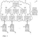
- Fig. 1 is a block diagram that schematically illustrates a computing system 20 supporting flexible in-network computing, in accordance with an embodiment that is described herein.
- Computing system 20 may be used in various applications such as, High Performance Computing (HPC) clusters, data center applications and Artificial Intelligence (AI), to name a few.
- HPC High Performance Computing
- AI Artificial Intelligence
- End node 28 communicates with one another over a communication network 32.
- End node 28 is also referred to herein as a "network node.”
- Communication network 32 may comprise any suitable type of a communication network operating using any suitable protocols such as, for example, an Infiniband TM network or an Ethernet network.
- End node 28 is coupled to the communication network using a Network Interface Controller (NIC) 36.
- NIC Network Interface Controller
- HCA Host Channel Adapter
- End node 28 may comprise any suitable processing module such as, for example, a server or a multi-core processing module comprising, for example, one or more Graphics Processing Units (GPUs) or other types of accelerators.
- GPUs Graphics Processing Units
- End node 28 typically comprises (not shown) multiple processing units such as Central Processing Units (CPUs) and Graphics Processing Units (GPUs), coupled via a suitable link (e.g., a PCIe) to a memory and peripheral devices, e.g., NIC 36.
- CPUs Central Processing Units
- GPUs Graphics Processing Units
- a suitable link e.g., a PCIe
- NIC 36 peripheral devices
- Communication network 32 comprises multiple network elements 24 interconnected in a multi-level configuration that enables performing complex in-network calculations using data reduction techniques.
- network elements 24 are arranged in a tree configuration having a lower level, a middle level and a top level, comprising network elements 24A, 24B and 24C, respectively.
- a network element 24A connects to multiple end nodes 28 using NICs 36.
- a practical computing system 20 may comprise several thousands or even tens of thousands of end nodes 28 interconnected using several hundreds or thousands of network elements 24.
- communication network 32 of computing system 20 may be configured in four-level Fat-Tree topology comprising on the order of 3,500 switches.
- a network element may connect to child network elements in a lower level or to network nodes, and to a parent network element in a higher level.
- a network element at the top level is also referred to as a root network element.
- a subset (or all) of the network elements of a physical tree structure may form a data reduction tree, which is a logical structure typically used for modeling in-network calculations, as will be described below.
- multiple network elements 24 perform a calculation for some or all of network nodes 28.
- the network elements collectively perform the calculation as modeled using a suitable data reduction tree.
- network elements in lower levels produce partial results that are aggregated by network elements in higher levels of the data reduction tree.
- a network element serving as the root of the data reduction tree produces the final calculation result (aggregated data), which is typically distributed to one or more network nodes 28.
- the calculation carried out by a network element 24 for producing a partial result is also referred to as a "data reduction operation.”
- the data flow from the network nodes toward the root is also referred to as "upstream,” and the data reduction tree used in the upstream direction is also referred to as an "upstream data reduction tree.”
- the data flow from the root toward the network nodes is also referred to as "downstream,” and the data reduction tree used in the downstream direction is also referred to as a “downstream data reduction tree.”
- Breaking a calculation over a data stream to a hierarchical in-network calculation by network elements 24 is typically carried out using a suitable data reduction protocol.
- An example data reduction protocol is the SHArP described in U.S. patent 10,284,383 cited above.
- network elements 24 support flexible usage of ports and computational resources for performing multiple data reduction operations in parallel. This enables flexible and efficient in-network computations in computing system 20.
- Fig. 2 is a block diagram that schematically illustrates a network element 24 supporting flexible data reduction operations in computing system 20 of Fig. 1 , in accordance with an embodiment that is described herein.
- Network element 24 may be used, for example, in implementing network elements 24A, 24B and 24C in communication network 32.
- Network element 24 comprises a central block 40 that manages the operation of the network element in accordance with the underlying data reduction protocol, e.g., the SHArP mentioned above.
- the functionality of central block 40 will be described in more detail below.
- Network element 24 further comprises configurable forwarding circuitry 42, which is connected using fixed connections 44 to various elements within network element 24.
- Forwarding circuitry 42 is flexibly configurable to interconnect among the various elements to which it connects. This allows creating various topologies of ports and computational resources for performing data reduction operations.
- forwarding circuitry 42 comprises a configurable crossbar switch. The flexibility in interconnections contributes to the ability to support full port bandwidth.
- Network element 24 comprises multiple ports 46 for connecting the network element to communication network 32. Each of ports 46 functions both as an input port for receiving packets from the communication network and as an output port for transmitting packets to the communication network.
- a practical network element 24 may comprise, for example, between 64 and 128 ports 46. Alternatively, a network element having any other suitable number of ports can also be used.
- each port 46 is respectively coupled to a transport-layer reception module 48, denoted “TRM-RX,” and to a transport-layer transmission module 52, denoted “TRM-TX.”
- the input part of port 46 is coupled to TRM-RX 48 via a parser 56.
- TRM-RX 48 comprises a QP responder 60 and a computational module 64, which is also referred to herein as an Arithmetic Logic Unit (ALU).
- ALU Arithmetic Logic Unit
- TRM-TX comprises QP requester 68.
- TRM-RX 48 further comprises a reception buffer 70 denoted RX-BUFFER for storing incoming packets.
- TRM-TX 52 further comprises a transmission buffer 71 denoted TX-BUFFER for storing outgoing packets.
- central block 40 controls the internal connectivity of forwarding circuitry 42 and the configurations of ALUs 64 so that the ports and the ALUs are interconnected in a topology suitable for performing a requested data reduction operation.
- Parser 56 is configured to parse incoming packets, and to identify and send relevant packets to TRM-RX 48.
- parser 56 identifies that a request for applying a data reduction operation is received and notifies the request to central block 40.
- the request may be indicative of a topology required in the upstream direction, a topology required in the downstream direction or both. Same or different ports may be used in the upstream topology and in the downstream topology, respectively.
- the data reduction operation itself e.g., indicative of the function to which ALUs 64 should be configured
- the upstream topology supports data reduction operations on data received from certain child network elements via multiple child ports, for producing reduced data destined to a given parent network element via a parent port.
- the downstream topology specifies a parent port for receiving aggregated data via a given parent port and distributing that aggregated data to certain child ports.
- the request is indicative of selected child ports, a selected parent port, and computational modules required for performing data reduction operations.
- the central block derives from the request a topology that interconnects among the selected child ports, selected parent port and ALUs, so as to perform data reduction operations and to forward the resulting reduced data to the selected parent port).
- the actual ALU function may be specified in the request or in a separate data message.
- the selected child ports receive data messages comprising a reduction operation and respective data portions and send the reduction operation to the central block, which sets the computational modules to apply the reduction operation to the data portions.
- the request is indicative of a given parent port and one or more given child ports
- the central block derives from the request, a topology that interconnects the given parent port to the one or more given child ports for receiving aggregated data from a respective parent network element via the given parent port and distributing the aggregated data via the given child ports to respective network elements or network nodes.
- Transport-layer modules TRM-RX 48 and TRM-TX 52 handle reliable connections with other entities via ports 46, such as ports of another network element or a port of a NIC of some network node 28.
- QP responder 60 in TRM-RX 48 handles reliable data reception via port 46.
- QP requester 68 in TRM-TX handles reliable data transmission via port 46.
- QP responder 60 receives packets transmitted by a corresponding QP requester, and signals back ACK/NACK notifications.
- QP requester 68 transmits packets to a corresponding QP responder on the other side of the link and handles re-transmissions as necessary.
- each port 46 has a local QP responder 60 and a local QP requester 68, communication among the network elements (and network nodes) can be carried out at wire speed and with minimal latency.
- This (and the flexible connectivity via the forwarding circuitry) allow executing multiple data reduction operations using respective disjoint data reduction trees, in parallel, at full port bandwidth.
- Network element 24 comprises one or more aggregators 72, each of which comprising an ALU 74, which is identical or similar to ALU 64 of TRM-RX module 48.
- Aggregator 72 does not receive data directly from any port 46. Instead, aggregator 72 aggregates data output by ALUs 64 of TRM-RXs 48. Aggregator 72 may also aggregate data output by an ALU 74 of another aggregator to create a hierarchical computational topology, in an embodiment.
- ALU 64 (and ALU 74) comprises two inputs and a single output. Let A1, and A2 denote input arguments and let A3 denote a result calculated by the ALU.
- ALUs 64 and 74 support any suitable operation such as, for example, mathematical functions such as integer and floating-point addition, multiplication and division, and logical functions such as logical AND, OR and XOR, bitwise AND, OR and XOR. Other operations supported by ALUs 64 and 74 comprise, for example, min, max, min loc, and max loc. In some embodiments ALUs 64 and 74 support configurable operators.
- data received via port 46 is provided to one input of ALU 64.
- ALU 64 may be configured to a Null function, in which case the other input of the ALU is ignored and the data received from the port is output by ALU 64 with no modification.
- ALU 64 receives on its other input (via the forwarding circuitry) data calculated by another ALU 64, and applies the function F() to the data received on both inputs.
- ALU 74 typically receives, via the forwarding circuitry, data output by two ALUs 64. In performing a data reduction operation, the participating ALUs 64 and ALU 74 are configured by the central block to a common function F(). Alternatively, at least some of the ALUs (64, 74 or both) assigned to a given data reduction operation may be configured to apply different functions.
- the output of ALU 64 may be routed via the forwarding circuitry as input to another ALU 64 (or ALU 74) as described above.
- the output of ALU 64 may be routed via the forwarding circuitry to a QP requester of the parent port for transmission to a parent network element.
- the output of the last ALU 64 that concludes the calculation specified by the underlying reduction tree may be routed to the QP requesters of the child ports participating in the downstream tree.
- computing system 20 and network element 24 in Figs. 1 and 2 are given by way of example, and other suitable computing system and network element configurations can also be used.
- network element 24 such as central block 40, forward circuitry 42 (possibly implemented as separate upstream crossbar 82 and downstream crossbar 84, in Figs. 5 and 6 below), ALU 64, ALU 74, parser 56, QP responder 60, QP requester 68, reception buffer 70 and transmission buffer 71 may be implemented in hardware, e.g., in one or more Application-Specific Integrated Circuits (ASICs) or Field-Programmable Gate Arrays (FPGAs). Additionally or alternatively, some elements of the network element can be implemented using software, or using a combination of hardware and software elements.
- ASICs Application-Specific Integrated Circuits
- FPGAs Field-Programmable Gate Arrays
- central block 40 may be carried out by a general-purpose processor, which is programmed in software to carry out the functions described herein.
- the software may be downloaded to the processor in electronic form, over a network, for example, or it may, alternatively or additionally, be provided and/or stored on non-transitory tangible media, such as magnetic, optical, or electronic memory.
- Figs. 3A and 3B are diagrams that schematically illustrate example data reduction schemes within network element 24, in accordance with embodiments that are described herein.
- ALUs 64 denoted ALU1...ALU4 are connected serially in a daisy-chain topology.
- the connections (in dotted lines) between successive ALUs 64 in the chain are implemented within forwarding circuitry 42 under the control of central block 40.
- ALU1...ALU4 receive data denoted D1...D4 from child network elements (or from network nodes 28) via respective ports denoted PORT1...PORT4 and are collectively configured to perform a data reduction operation.
- the data reduction operation calculates the sum (D1+D2+D3+D4).
- ALU1 is configured to transfer D1 to the output of ALU1 and each of ALU2...ALU4 calculates a sum function between its inputs. The calculation is carried out accumulatively as follows: ALU2 outputs the sum (D1+D2), ALU3 outputs the sum [(D1+D2)+D3], and ALU4 outputs the final sum ⁇ [(D1+D2)+D3]+D4 ⁇ .
- the data reduction result (D1+D2+D3+D4) output by ALU4 is routed via forwarding circuitry 42 to a parent network element via PORTS.
- ALUs 64 denoted ALU1...ALU4 and ALU 74 denoted ALU5 are connected in an aggregated topology.
- the connections (in dotted lines) from each ALU output to the input of the next ALU are implemented within forwarding circuitry 42 under the control of central block 40.
- ALU1...ALU4 receive data denoted D1...D4 from child network elements via respective ports denoted PORT1...PORT4 and together with ALU5 are collectively configured to perform a data reduction operation, in the present example calculating the sum (D1+D2+D3+D4).
- the topology in Fig.3B comprises a first chain comprising ALU1 and ALU2 and a second chain comprising ALU3 and ALU4.
- the forwarding circuitry connects the outputs of ALU2 and of ALU4 to the inputs of ALU5.
- ALU1 and ALU3 are configured to transfer their input data (D1 and D3) to their respective outputs, and each of ALU2, ALU4 and ALU5 calculates the sum of its inputs.
- the chain comprising ALU1 and ALU2 calculates a partial sum (D1+D2) and the chain comprising ALU3 and ALU4 calculates a partial sum (D3+D4).
- ALU 5 calculates the aggregated result [(D1+D2)+(D3+D4)], which the forwarding circuitry routes to port5 for transmission to a parent network element.
- Figs. 3A and 3B two different topologies in which the ports and ALUs are interconnected are used in calculating the same sum (D1+D2+D3+D4).
- Fig. 3A the calculation is accumulated over a chain of four ALUs.
- Fig. 3B the calculation aggregates two short chains, and therefore the calculation latency in Fig. 3B is shorter than in Fig. 3A .
- Figs. 3A and 3B are given by way of example, and other suitable topologies can also be used.
- forwarding circuitry 42 is flexibly configurable, complex topologies with multiple aggregation levels using multiple aggregators 72 can be used.
- different groups of ports and ALUs may be allocated by central block 40 to perform multiple respective data reduction operations in parallel. This allows computing system 20 to perform multiple high-bandwidth in-network computations in parallel, using disjoint data reduction trees having separate respective groups of ports and ALUs within each network element.
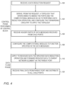
- Fig. 4 is a flow chart that schematically illustrates a method for performing a data reduction operation in network element 24, in accordance with an embodiment that is described herein.
- the method of Fig. 4 begins with central block 40 receiving a data reduction request, in accordance with a data reduction protocol, at a request reception step 100.
- the central block may receive the data reduction request from one or more child network elements or using some out-of-band link.
- the data reduction request comprises information regarding a data reduction tree to be implemented by the network element, typically as part of executing a calculation by computing system 20 using a suitable data reduction tree.
- the request is indicative of selected child ports, a selected parent port and computational modules required for applying data reduction operations.
- the same data reduction request supports multiple different reduction operations on data that will be received from certain child network elements via the selected child ports, for producing reduced data destined to a parent network element via the selected parent port.
- Performing the data reduction operation typically requires data manipulation using ALUs 64, possibly with one or more ALUs 74 of aggregators 72.
- the same selected child ports and selected parent port are used in both the upstream and downstream directions.
- central block 40 derives, from the data reduction request, a topology that interconnects among the selected child ports, the selected parent port, and computational modules (ALUs 64, 74 or both) so as to perform data reduction operations and to forward the reduced data for transmission to the selected parent port. Further at step 104, the central block configures forwarding circuitry 42 to apply the derived topology.
- the topology routes the aggregated data calculated by the last ALU to the QP requesters of relevant the child ports that distribute the aggregated data in accordance with a corresponding downstream tree.
- the central block receives header parts of data messages received from child network elements or network nodes, via the selected child ports.
- Each data message comprises multiple packets.
- the data message specifies, e.g., in the header part (e.g., in the first packet), the data reduction operation to be performed using the already configured topology.
- parser 56 sends the header part of the data message to the control block and forwards the payload data of the data message to the relevant computational module.
- central block 40 configures the computational modules that participate in the data reduction operations to a function specified in the header of the data message (s) .
- Step 108 is relevant to the upstream direction and may be skipped in the downstream direction.
- the computational modules assigned based on the data message apply to the data payloads received in the data messages the specified data reduction operation, and the resulting reduced data is sent to the parent network element via the selected parent port.
- the resulting reduced data comprises the aggregated data, which is sent via the forwarding circuitry to all the selected child ports.
- the network element receives aggregated data from the selected parent port, and distributes the aggregated data, via the forwarding circuitry, to the selected child ports. Following step 120 the method terminates.
- each QP requester of the parent port and child ports is responsible for sending the messages on a reliable connection or on the transport layer.
- the method of Fig. 4 may be executed similarly assuming different upstream and downstream data reduction trees.
- different sets of selected child ports and a parent port may be used for the respective upstream and downstream directions.
- Figs. 5 and 6 are diagrams that schematically illustrate upstream and downstream data reduction flows within network element 24, in accordance embodiments that is described herein.
- forwarding circuitry 42 comprises upstream forwarding circuitry 82 and downstream forwarding circuitry 84, which may be implemented as separate crossbar elements.
- forwarding circuitry 42 comprises separate upstream crossbar 82 and downstream crossbar 84, and that the same data reduction tree is used for both the upstream and downstream directions.
- central block 40 configures upstream crossbar 82 to connect among ports 46 and computational modules (ALUs 64 and ALU 74 of aggregator 72) in accordance with an upstream data reduction tree.
- the central block configures ports 46A and 46B for receiving data for reduction from child network elements and configures port 46C for transmitting the calculated reduced data to a parent network element.
- Central block 40 additionally configures the upstream crossbar to connect ALUs 64A and 64B serially in a chain configuration whose output connects to an input of ALU 74. The other input of ALU 74 connects via the upstream crossbar to another chain of ALUs 64 (not shown).
- QP responders 60A and 60B of respective ports 46A and 46B receive packets of data messages from the child network elements.
- each packet comprises a transport layer header and a payload
- the first packet of the data message additionally comprises a SHArP header.
- the QP responder of each port handles the transport layer, and after sending the SHArP header to the central block forwards the payloads of the packets to ALU 64 of that port.
- TRM-RX modules 48 of the child ports forward the SHArP header of the first packet to the central block, which at step (4) prepares a SHArP header for transmitting the reduced data. Further at step (4) the central block sets ALUs 64 and 74 to apply a function specified in the first packet.
- ALUs 64A and 64B perform data reduction to the payload received in each data message via child ports 46A and 46B.
- ALU 74 of aggregator 72 receives partially reduced data from ALU 64B and from the other chain, and at step (9) ALU 74 calculates the overall reduced data.
- the reduced data is forwarded to port 46C for transmission to the parent network element.
- QP requestor 68C packetizes a reduced data message that contains the reduced data and the SHArP header of step (4) and rebuilds the transport layer by attaching to each packet of the reduced data message a transport layer header.
- QP requester 68C handles reliable transport layer packet transmission, including retransmissions.
- the QP requester uses some storage space of a local buffer (e.g., transmission buffer 71) of the port as a retry buffer for retransmission.
- the network element applies a suitable scheduling scheme (not shown) for packet transmission via port 46C including, for example, bandwidth allocation and prioritization using Virtual Lane (VL) management.
- VL Virtual Lane
- central block 40 configures downstream crossbar 84 to connect among ports 46 for distributing aggregated data received from a parent network element to multiple child network elements, in accordance with a downstream data reduction tree.
- the central block configures parent port 46C for receiving aggregated data from the parent network element, and configures child ports 46A and 46B for transmitting the aggregated data to respective child network elements or end nodes.
- Central block 40 additionally configures the downstream crossbar to forward the aggregated data to both child ports 46A and 46B in parallel.
- QP responder 60C of port 46C receives packets carrying aggregated data, in an aggregated data message, from the parent network element.
- each packet comprises a transport layer header and a payload
- the first packet additionally comprises a SHArP header.
- QP responder 60C handles the transport layer, and after sending the SHArP header to the central block forwards the payloads of the packets to the downstream crossbar.
- the payloads of the packets are forwarded via ALU 64C that is configured by the central block to a Null function, so that the packet payload is transferred by the ALU with no modification.
- ALU 64C is bypassed, and the packet payload is forwarded directly to the downstream crossbar, as will be described at step (5) below.
- TRM-RX 48C of port 46C forwards the SHArP header of the received packet to central block 40, and at step (4) the central block prepares a SHArP header for transmitting with the aggregated data to the child network elements.
- the downstream crossbar receives the payload of the aggregated data message and forwards the payload to both child ports 46A and 46B in parallel.
- each of QP requesters 68A and 68B packetizes an aggregated data message that contains the aggregated data and the SHArP header of step (4) and rebuilds the transport layer by attaching to each packet of the aggregated message a transport layer header.
- QP requesters 68A and 68B handle transport layer packet transmission, including retransmissions.
- the QP requester may use storage space of a local buffer (e.g., transmission buffer 71) of the port as a retry buffer for retransmission.
- the network element applies a suitable scheduling scheme (not shown) for packet transmission to ports 46A and 46B including, for example, bandwidth allocation and prioritization using Virtual Lane (VL) management.
- VL Virtual Lane
- upstream and downstream directions are described separately.
- same or different respective topologies for the upstream and downstream directions may be applied in parallel using a dedicated crossbar for each direction, e.g., for calculating a reduced data and distributing the resulting aggregated data.
Landscapes
- Engineering & Computer Science (AREA)
- Computer Networks & Wireless Communication (AREA)
- Signal Processing (AREA)
- Computer Security & Cryptography (AREA)
- Quality & Reliability (AREA)
- Data Exchanges In Wide-Area Networks (AREA)
Description
- Embodiments described herein relate generally to in-network computing, and particularly to a network element and a method for supporting flexible data reduction operations.
- Some computing systems support performing computation tasks by network elements of a communication system. Methods for distributing a computation among multiple network elements are known in the art. For example,
U.S. patent 10,284,383 -
US2018091442 describes a network switch architecture supporting multiple simultaneous collective operations.US9294551 B1 US2017255501 describes in-node aggregation and disaggregation of MPI alltoall and alltoallv collectives. - The invention is defined by the claims. In order to illustrate the invention, aspects and embodiments which may or may not fall within the scope of the claims are described herein. An embodiment that is described herein provides a network element that includes a plurality of ports, multiple computational modules, configurable forwarding circuitry and a central block. The plurality of ports includes multiple child ports coupled to respective child network elements or network nodes and one or more parent ports coupled to respective parent network elements. The plurality of ports being configured to connect to a communication network. At least two of the plurality of ports have local computational modules configured to be interconnected via the forwarding circuitry to collectively perform a data reduction operation in accordance with a data reduction protocol. The configurable forwarding circuitry is configured to interconnect among the ports and the computational modules. The central block is configured to receive a request indicative of selected child ports, a selected parent port, and computational modules required for performing data reduction operations on data received from the child network elements or network nodes via the selected child ports, for producing reduced data destined to a parent network element via the selected parent port, to derive, from the request, a topology that interconnects among the selected child ports, the selected parent port and the computational modules so as to perform the data reduction operations and to forward the respective reduced data for transmission to the selected parent port, and to configure the forwarding circuitry to apply the topology.
- In some embodiments, the selected child ports are configured to receive data messages including a reduction operation and respective data portions, and to send the reduction operation to the central block, and the central block is configured to set the computational modules to apply the reduction operation to the data portions. In other embodiments, the central block is configured to derive the topology to interconnect computational modules that receive data for reduction via the selected child ports, in a chain configuration.
- In yet other embodiments, the central block is configured to derive the topology to interconnect outputs of two computational modules that receive data for reduction via the selected child ports as inputs to an aggregator computational module.
- In an embodiment, the selected parent port and each of the selected child ports include a QP responder and a QP requester, configured to respectively handle reliable transport layer reception and transmission of packets. In another embodiment, the central block is configured to receive a first request indicative of first child ports, a first parent port and first computational modules required to perform first data reduction operations on data received via the first child ports and destined to the first parent port, and further receive a second request indicative of second child ports, a second parent port, and second computational modules required to perform second data reduction operations on data received via the second child ports and destined to the second parent port, to derive from the first request a first topology for performing the first data reduction operations and derive from the second request a second topology for performing the second data reduction operations, and to configure the forwarding circuitry to apply both the first topology and the second topology so as to support performing the first data reduction operations and the second data reduction operations in parallel. In yet another embodiment, the request is indicative of the network element serving as a root network element, and the central block is configured to derive from the request a topology that interconnects among the selected child ports and the computational modules so as to perform the data reduction operations for producing aggregated data and to route the aggregated data to one or more child ports.
- In some embodiments, the request or a separately received request is indicative of a given parent port and one or more given child ports, and the central block is configured to derive from the request, a topology that interconnects the given parent port to the one or more given child ports for receiving aggregated data from a respective parent network element via the given parent port and distributing the aggregated data via the given child ports to respective network elements or network nodes. In other embodiments, the forwarding circuitry includes upstream forwarding circuitry and downstream forwarding circuitry, and the central block is configured to apply, in parallel, an upstream topology to the upstream forwarding circuitry for applying the data reduction operations, and to apply a downstream topology to the downstream forwarding circuitry for distributing aggregated data produced by a root network element toward one or more network nodes.
- There is additionally provided, in accordance with an embodiment that is described herein, a method including, in a network element including (i) a plurality of ports that connect to a communication network, including multiple child ports coupled to respective child network elements or network nodes and one or more parent ports coupled to respective parent network elements, and (ii) forwarding circuitry, wherein at least two of the plurality of ports have local computational modules configured to be connected via the forwarding circuitry to collectively perform a data reduction operation in accordance with a data reduction protocol, wherein the forwarding circuitry is configurable to interconnect among the ports and the computational modules, receiving by a central block of the network element a request indicative of selected child ports, a selected parent port, and computational modules required for performing data reduction operations on data received via the selected child ports, for producing reduced data destined to a parent network element via the selected parent port. A topology is derived, from the request, that interconnects among the selected child ports, the selected parent port and the computational modules so as to perform data reduction operations, and to forward the reduced data for transmission to the selected parent port. The topology is applied by the forwarding circuitry.
- In some embodiments, the method further comprises receiving via the selected child ports data messages comprising a reduction operation and respective data portions, sending the reduction operation to the central block, and setting the computational modules, by the central block, to apply the reduction operation to the data portions. In other embodiments, deriving the topology comprises deriving the topology to interconnect computational modules that receive data for reduction via the selected child ports in a chain configuration. In yet other embodiments, deriving the topology comprises deriving the topology to interconnect outputs of two computational modules that receive data for reduction via the selected child ports as inputs to an aggregator computational module.
- In an embodiment, the selected parent port and each of the selected child ports comprise a QP responder and a QP requester, and comprising respectively handling, using the QP requester and the QP responder reliable transport layer reception and transmission of packets. In another embodiment, the method further comprises receiving a first request indicative of first child ports, a first parent port and first computational modules required to perform first data reduction operations on data received via the first child ports and destined to the first parent port, and further receiving a second request indicative of second child ports, a second parent port, and second computational modules required to perform second data reduction operations on data received via the second child ports and destined to the second parent port; deriving, from the first request a first topology for performing the first data reduction operations and deriving from the second request a second topology for performing the second data reduction operations; and configuring the forwarding circuitry to apply both the first topology and the second topology so as to support performing the first data reduction operations and the second data reduction operations in parallel. In yet another embodiment, the request is indicative of the network element serving as a root network element, and comprising deriving from the request a topology that interconnects among the selected child ports and the computational modules so as to perform the data reduction operations for producing aggregated data and to route the aggregated data to one or more child ports.
- In some embodiments, the request or a separately received request is indicative of a given parent port and one or more given child ports, and comprising deriving from the request, a topology that interconnects the given parent port to the one or more given child ports for receiving aggregated data from a respective parent network element via the given parent port and distributing the aggregated data via the given child ports to respective network elements or network nodes. In other embodiments, the forwarding circuitry comprises upstream forwarding circuitry and downstream forwarding circuitry, and the method comprises applying, in parallel, an upstream topology to the upstream forwarding circuitry for applying the data reduction operations, and applying a downstream topology to the downstream forwarding circuitry for distributing aggregated data produced by a root network element toward one or more network nodes.
- In an embodiment, a network element includes a plurality of ports, multiple computational modules, configurable forwarding circuitry and a central block. The ports include child ports coupled to child network elements or network nodes and parent ports coupled to parent network elements. The computational modules collectively perform a data reduction operation of a data reduction protocol. The forwarding circuitry interconnects among ports and computational modules. The central block receives a request indicative of child ports, a parent port, and computational modules required for performing reduction operations on data received via the child ports, for producing reduced data destined to the parent port, to derive from the request a topology that interconnects among the child ports, parent port and computational modules for performing the data reduction operations and to forward the reduced data for transmission to the selected parent port, and to configure the forwarding circuitry to apply the topology.
- Any feature of one aspect or embodiment may be applied to other aspects or embodiments, in any appropriate combination. In particular, any feature of a method aspect or embodiment may be applied to an apparatus aspect or embodiment, and vice versa.
- These and other embodiments will be more fully understood from the following detailed description of the embodiments thereof, taken together with the drawings in which:
-
-
Fig. 1 is a block diagram that schematically illustrates a computing system supporting flexible in-network computing, in accordance with an embodiment that is described herein; -
Fig. 2 is a block diagram that schematically illustrates a network element supporting flexible data reduction operations in the computing system ofFig. 1 , in accordance with an embodiment that is described herein; -
Figs. 3A and 3B are diagrams that schematically illustrate example data reduction schemes within a network element, in accordance with embodiments that are described herein; -
Fig. 4 is a flow chart that schematically illustrates a method for performing a data reduction operation in a network element, in accordance with an embodiment that is described herein; and -
Figs. 5 and6 are diagrams that schematically illustrates upstream and downstream data reduction flows within a network element, in accordance embodiments that is described herein. - Embodiments that are described herein provide a network element and a method for in-network computing using network elements that support flexible data reduction operations.
- In-network computing involves dividing a calculation over a stream of data into multiple sub-calculations executed by network elements of a communication network. A network element may comprise any suitable network device such as, for example, a switch or a router.
- In some embodiments, an in-network calculation is carried out hierarchically by multiple network elements arranged in a multi-level configuration. Network elements of the lowest level receive portions of the data stream from multiple network nodes and based on the data portions produce partial results. Elements of higher levels further aggregate the partial results up to a root network element that produces a final calculation result. The root network element typically distributes the final calculation result to some or all of the network nodes that provided the data, and/or to other network elements.
- A partial result produced by a network element as part of an in-network calculation is also referred to herein as a "reduced data" and the final result produced by the root network element is also referred to herein as an "aggregated data." A logical structure that models the hierarchical in-network calculation is referred to as a "data reduction tree."
- In-network calculations are often implemented in accordance with a data reduction protocol. An example data reduction protocol of this sort is the Scalable Hierarchical Aggregation and Reduction Protocol (SHArP™) described in
U.S. patent 10,284,383 - An important requirement in implementing in-network computing is to efficiently carry out multiple complex calculations over multiple respective high-bandwidth data streams in parallel and with low latency. Some aspects of accelerating data reduction operations in hardware are described, for example, in
U.S. patent application number 16/357,356, of Elias et al., filed March 19, 2019 - In principle, multiple data reduction trees may be used for modeling multiple respective in-network calculations in parallel. Such data reduction trees, however, may use separate sets of ports and computational resources across respective network elements, in which case they can maintain full port bandwidth. Reduction trees that do not share ports are also referred to as "disjoint reduction trees."
- In the disclosed embodiments, each network element comprises multiple computational modules for performing data reduction operations in hardware. In some embodiments, each port that receives data for reduction has a respective computational module. The computational modules and ports may be interconnected using configurable forwarding circuitry in various topologies. This allows flexible usage of the computational modules in separate reduction trees without sharing port bandwidth.
- Consider a network element, comprising a plurality of ports coupled to network elements and/or network nodes. Ports coupled to respective child network elements or network nodes are referred to as "child ports" and ports coupled to respective parent network elements are referred to as "parent ports." The network element further comprises multiple computational modules, configurable forwarding circuitry and a central block. The ports are configured to connect to a communication network. The multiple computational modules are configured to collectively perform a data reduction operation, in accordance with a data reduction protocol. The forwarding circuitry is configured to interconnect among the ports and the computational modules. The central block is configured to receive a request indicative of selected child ports, a selected parent port, and computational modules required for performing data reduction operations on data received via the selected child ports, for producing reduced data destined to a parent network element via the selected parent port. The central block derives from the request a topology that interconnects among the selected child ports, the selected parent port and the computational modules so as to perform the requested data reduction operations and to forward the reduced data for transmission to the selected parent port, and configures the forwarding circuitry to apply the topology.
- In some embodiments, the selected child ports are configured to receive data messages comprising a reduction operation and respective data portions, and to send the reduction operation to the central block. The central block is configured to set the computational modules to apply the reduction operation to the data portions.
- The central block may derive the topology in any suitable way. For example, the central block derives a topology that interconnects multiple computational modules that receive data from child ports in a chain configuration, or in an aggregated configuration that aggregates two or more chains. In some embodiments, the network element stores multiple predefined topologies, e.g., in a table in memory. In such embodiments, the central block derives a requested topology by retrieving it from the table.
- In some embodiments, each of the parent port and the child ports comprises a QP responder and a QP requester, that handle reliable transport layer communication of packets related to the data reduction protocol. Handling transport layer communication at the port level (and not by a central element such as the central block) allows fast and reliable packet delivery to and from other network elements and network nodes, at full port bandwidth.
- In some embodiments, the central block receives a first data reduction request indicative of first child ports, a first parent port and first computational modules required to perform a first data reduction operations on data received via the first child ports and destined to a the first parent port, and further receives a second data reduction request indicative of second child ports, a second parent port, and second computational modules required to perform a second data reduction operations on data received via the second child ports and destined to a the second parent port. The central block derives from the first request a first topology for performing the first data reduction operations and derives from the second request a second topology for performing the second data reduction operations. The central block configures the forwarding circuitry to apply both the first topology and the second topology so as to support performing the first data reduction operations and the second data reduction operations in parallel.
- The first and second topologies may use disjoint subsets of ports and computational modules. The central block may configure the forwarding circuitry to apply the derived first and second topologies so that respective data first and second reduction operations are executed at full port bandwidth, and may overlap in time.
- In some embodiments, the request is indicative of the network element serving as a root network element, and the central block derives from the request a topology that interconnects among the selected child ports and the computational modules so as to perform data reduction operations for producing aggregated data and to route the aggregated data to one or more child ports.
- In an embodiment, the request or a separately received request is indicative of a given parent port and one or more given child ports, and the central block is configured to derive from the request a topology that interconnects the given parent port to the one or more given child ports, for receiving aggregated data from a respective parent network element via the given parent port and distributing the aggregated data via the given child ports to respective network elements or network nodes.
- In an embodiment, the forwarding circuitry comprises upstream forwarding circuitry and downstream forwarding circuitry. In this embodiment, the central block applies in parallel an upstream topology to the upstream forwarding circuitry for applying the data reduction operations, and applies a downstream topology to the downstream forwarding circuitry for distributing aggregated data produced by a root network element toward one or more network nodes.
- In the disclosed techniques a network element supports flexible interconnections among ports and computational modules, without unnecessarily using computational modules for just passing data, thus refraining from bandwidth sharing. Ports that receive data for reduction have local computational modules that may be interconnected, e.g., in a serial chain having a suitable length, or in an aggregated configuration that aggregates multiple chains. This flexibility in connecting computational modules via the forwarding circuitry allows efficient usage of limited resources in performing different data reduction operations at different times, and/or in performing multiple data reduction operations in parallel without sharing port bandwidth.
-
Fig. 1 is a block diagram that schematically illustrates acomputing system 20 supporting flexible in-network computing, in accordance with an embodiment that is described herein. -
Computing system 20 may be used in various applications such as, High Performance Computing (HPC) clusters, data center applications and Artificial Intelligence (AI), to name a few. - In
computing system 20,multiple end nodes 28 communicate with one another over acommunication network 32. "End node" 28 is also referred to herein as a "network node."Communication network 32 may comprise any suitable type of a communication network operating using any suitable protocols such as, for example, an Infiniband™ network or an Ethernet network.End node 28 is coupled to the communication network using a Network Interface Controller (NIC) 36. In Infiniband terminology, the network interface is referred to as a Host Channel Adapter (HCA).End node 28 may comprise any suitable processing module such as, for example, a server or a multi-core processing module comprising, for example, one or more Graphics Processing Units (GPUs) or other types of accelerators.End node 28 typically comprises (not shown) multiple processing units such as Central Processing Units (CPUs) and Graphics Processing Units (GPUs), coupled via a suitable link (e.g., a PCIe) to a memory and peripheral devices, e.g.,NIC 36. -
Communication network 32 comprisesmultiple network elements 24 interconnected in a multi-level configuration that enables performing complex in-network calculations using data reduction techniques. In the present example,network elements 24 are arranged in a tree configuration having a lower level, a middle level and a top level, comprisingnetwork elements network element 24A connects tomultiple end nodes 28 usingNICs 36. - A
practical computing system 20 may comprise several thousands or even tens of thousands ofend nodes 28 interconnected using several hundreds or thousands ofnetwork elements 24. For example,communication network 32 ofcomputing system 20 may be configured in four-level Fat-Tree topology comprising on the order of 3,500 switches. - In the multi-level tree structure, a network element may connect to child network elements in a lower level or to network nodes, and to a parent network element in a higher level. A network element at the top level is also referred to as a root network element. A subset (or all) of the network elements of a physical tree structure may form a data reduction tree, which is a logical structure typically used for modeling in-network calculations, as will be described below.
- In some embodiments,
multiple network elements 24 perform a calculation for some or all ofnetwork nodes 28. The network elements collectively perform the calculation as modeled using a suitable data reduction tree. In the hierarchical calculation, network elements in lower levels produce partial results that are aggregated by network elements in higher levels of the data reduction tree. A network element serving as the root of the data reduction tree produces the final calculation result (aggregated data), which is typically distributed to one ormore network nodes 28. The calculation carried out by anetwork element 24 for producing a partial result is also referred to as a "data reduction operation." - The data flow from the network nodes toward the root is also referred to as "upstream," and the data reduction tree used in the upstream direction is also referred to as an "upstream data reduction tree." The data flow from the root toward the network nodes is also referred to as "downstream," and the data reduction tree used in the downstream direction is also referred to as a "downstream data reduction tree."
- Breaking a calculation over a data stream to a hierarchical in-network calculation by
network elements 24 is typically carried out using a suitable data reduction protocol. An example data reduction protocol is the SHArP described inU.S. patent 10,284,383 - As will be described below,
network elements 24 support flexible usage of ports and computational resources for performing multiple data reduction operations in parallel. This enables flexible and efficient in-network computations incomputing system 20. -
Fig. 2 is a block diagram that schematically illustrates anetwork element 24 supporting flexible data reduction operations incomputing system 20 ofFig. 1 , in accordance with an embodiment that is described herein. -
Network element 24 may be used, for example, in implementingnetwork elements communication network 32. -
Network element 24 comprises acentral block 40 that manages the operation of the network element in accordance with the underlying data reduction protocol, e.g., the SHArP mentioned above. The functionality ofcentral block 40 will be described in more detail below. -
Network element 24 further comprisesconfigurable forwarding circuitry 42, which is connected using fixedconnections 44 to various elements withinnetwork element 24. Forwardingcircuitry 42 is flexibly configurable to interconnect among the various elements to which it connects. This allows creating various topologies of ports and computational resources for performing data reduction operations. In an embodiment, forwardingcircuitry 42 comprises a configurable crossbar switch. The flexibility in interconnections contributes to the ability to support full port bandwidth. -
Network element 24 comprisesmultiple ports 46 for connecting the network element tocommunication network 32. Each ofports 46 functions both as an input port for receiving packets from the communication network and as an output port for transmitting packets to the communication network. Apractical network element 24 may comprise, for example, between 64 and 128ports 46. Alternatively, a network element having any other suitable number of ports can also be used. - In some embodiments, each
port 46 is respectively coupled to a transport-layer reception module 48, denoted "TRM-RX," and to a transport-layer transmission module 52, denoted "TRM-TX." The input part ofport 46 is coupled to TRM-RX 48 via aparser 56. TRM-RX 48 comprises aQP responder 60 and acomputational module 64, which is also referred to herein as an Arithmetic Logic Unit (ALU). TRM-TX comprisesQP requester 68. TRM-RX 48 further comprises areception buffer 70 denoted RX-BUFFER for storing incoming packets. TRM-TX 52 further comprises atransmission buffer 71 denoted TX-BUFFER for storing outgoing packets. - In some embodiments,
central block 40 controls the internal connectivity of forwardingcircuitry 42 and the configurations ofALUs 64 so that the ports and the ALUs are interconnected in a topology suitable for performing a requested data reduction operation. -
Parser 56 is configured to parse incoming packets, and to identify and send relevant packets to TRM-RX 48. - In some embodiments,
parser 56 identifies that a request for applying a data reduction operation is received and notifies the request tocentral block 40. The request may be indicative of a topology required in the upstream direction, a topology required in the downstream direction or both. Same or different ports may be used in the upstream topology and in the downstream topology, respectively. The data reduction operation itself (e.g., indicative of the function to whichALUs 64 should be configured) may be specified in the request that is indicative of the topology (or topologies) or alternatively, carried in a header of a data message. - The upstream topology supports data reduction operations on data received from certain child network elements via multiple child ports, for producing reduced data destined to a given parent network element via a parent port. The downstream topology specifies a parent port for receiving aggregated data via a given parent port and distributing that aggregated data to certain child ports.
- In the upstream direction, the request is indicative of selected child ports, a selected parent port, and computational modules required for performing data reduction operations. The central block derives from the request a topology that interconnects among the selected child ports, selected parent port and ALUs, so as to perform data reduction operations and to forward the resulting reduced data to the selected parent port). As noted above, the actual ALU function may be specified in the request or in a separate data message.
- In some embodiments, the selected child ports receive data messages comprising a reduction operation and respective data portions and send the reduction operation to the central block, which sets the computational modules to apply the reduction operation to the data portions.
- In the downstream direction, the request is indicative of a given parent port and one or more given child ports, and the central block derives from the request, a topology that interconnects the given parent port to the one or more given child ports for receiving aggregated data from a respective parent network element via the given parent port and distributing the aggregated data via the given child ports to respective network elements or network nodes.
- Transport-layer modules TRM-
RX 48 and TRM-TX 52 handle reliable connections with other entities viaports 46, such as ports of another network element or a port of a NIC of somenetwork node 28.QP responder 60 in TRM-RX 48 handles reliable data reception viaport 46. QP requester 68 in TRM-TX handles reliable data transmission viaport 46. - In some embodiments,
QP responder 60 receives packets transmitted by a corresponding QP requester, and signals back ACK/NACK notifications. QP requester 68 transmits packets to a corresponding QP responder on the other side of the link and handles re-transmissions as necessary. - Note that since each
port 46 has alocal QP responder 60 and a local QP requester 68, communication among the network elements (and network nodes) can be carried out at wire speed and with minimal latency. This (and the flexible connectivity via the forwarding circuitry) allow executing multiple data reduction operations using respective disjoint data reduction trees, in parallel, at full port bandwidth. -
Network element 24 comprises one ormore aggregators 72, each of which comprising anALU 74, which is identical or similar toALU 64 of TRM-RX module 48.Aggregator 72 does not receive data directly from anyport 46. Instead, aggregator 72 aggregates data output byALUs 64 of TRM-RXs 48.Aggregator 72 may also aggregate data output by anALU 74 of another aggregator to create a hierarchical computational topology, in an embodiment. - The functionality of
ALU 64 as will described below, also applies similarly toALU 74. In the present example, ALU 64 (and ALU 74) comprises two inputs and a single output. Let A1, and A2 denote input arguments and let A3 denote a result calculated by the ALU. The ALU typically supports multiple predefined functions to which the ALU may be configured by the central block. When configured to a given function "F()", the ALU calculates A3 as A3=F(A1, A2).ALUs ALUs embodiments ALUs - In some embodiments, data received via port 46 (from a child network element or from a network node) is provided to one input of
ALU 64.ALU 64 may be configured to a Null function, in which case the other input of the ALU is ignored and the data received from the port is output byALU 64 with no modification. Alternatively,ALU 64 receives on its other input (via the forwarding circuitry) data calculated by anotherALU 64, and applies the function F() to the data received on both inputs.ALU 74 typically receives, via the forwarding circuitry, data output by twoALUs 64. In performing a data reduction operation, the participatingALUs 64 andALU 74 are configured by the central block to a common function F(). Alternatively, at least some of the ALUs (64, 74 or both) assigned to a given data reduction operation may be configured to apply different functions. - The output of
ALU 64 may be routed via the forwarding circuitry as input to another ALU 64 (or ALU 74) as described above. Alternatively, the output ofALU 64 may be routed via the forwarding circuitry to a QP requester of the parent port for transmission to a parent network element. In a root network element, the output of thelast ALU 64 that concludes the calculation specified by the underlying reduction tree may be routed to the QP requesters of the child ports participating in the downstream tree. - The configurations of
computing system 20 andnetwork element 24 inFigs. 1 and2 , as well asnetwork element 24 inFigs. 5 and6 below, are given by way of example, and other suitable computing system and network element configurations can also be used. - Some elements of
network element 24, such ascentral block 40, forward circuitry 42 (possibly implemented as separateupstream crossbar 82 anddownstream crossbar 84, inFigs. 5 and6 below),ALU 64,ALU 74,parser 56,QP responder 60, QP requester 68,reception buffer 70 andtransmission buffer 71 may be implemented in hardware, e.g., in one or more Application-Specific Integrated Circuits (ASICs) or Field-Programmable Gate Arrays (FPGAs). Additionally or alternatively, some elements of the network element can be implemented using software, or using a combination of hardware and software elements. - Elements that are not necessary for understanding the principles of the present application, such as various interfaces, addressing circuits, timing and sequencing circuits and debugging circuits, have been omitted from
Figs. 1 ,2 ,5 and6 for clarity. - In some embodiments, some of the functions of
central block 40 may be carried out by a general-purpose processor, which is programmed in software to carry out the functions described herein. The software may be downloaded to the processor in electronic form, over a network, for example, or it may, alternatively or additionally, be provided and/or stored on non-transitory tangible media, such as magnetic, optical, or electronic memory. -
Figs. 3A and 3B are diagrams that schematically illustrate example data reduction schemes withinnetwork element 24, in accordance with embodiments that are described herein. - In
Fig. 3A ,ALUs 64 denoted ALU1...ALU4 are connected serially in a daisy-chain topology. The connections (in dotted lines) betweensuccessive ALUs 64 in the chain are implemented within forwardingcircuitry 42 under the control ofcentral block 40. - ALU1...ALU4 receive data denoted D1...D4 from child network elements (or from network nodes 28) via respective ports denoted PORT1...PORT4 and are collectively configured to perform a data reduction operation. In the present example, the data reduction operation calculates the sum (D1+D2+D3+D4). To this end, ALU1 is configured to transfer D1 to the output of ALU1 and each of ALU2...ALU4 calculates a sum function between its inputs. The calculation is carried out accumulatively as follows: ALU2 outputs the sum (D1+D2), ALU3 outputs the sum [(D1+D2)+D3], and ALU4 outputs the final sum {[(D1+D2)+D3]+D4}. The data reduction result (D1+D2+D3+D4) output by ALU4 is routed via forwarding
circuitry 42 to a parent network element via PORTS. - In
Fig. 3B ,ALUs 64 denoted ALU1...ALU4 andALU 74 denoted ALU5 are connected in an aggregated topology. The connections (in dotted lines) from each ALU output to the input of the next ALU are implemented within forwardingcircuitry 42 under the control ofcentral block 40. - ALU1...ALU4 receive data denoted D1...D4 from child network elements via respective ports denoted PORT1...PORT4 and together with ALU5 are collectively configured to perform a data reduction operation, in the present example calculating the sum (D1+D2+D3+D4). The topology in
Fig.3B comprises a first chain comprising ALU1 and ALU2 and a second chain comprising ALU3 and ALU4. The forwarding circuitry connects the outputs of ALU2 and of ALU4 to the inputs of ALU5. ALU1 and ALU3 are configured to transfer their input data (D1 and D3) to their respective outputs, and each of ALU2, ALU4 and ALU5 calculates the sum of its inputs. - The chain comprising ALU1 and ALU2 calculates a partial sum (D1+D2) and the chain comprising ALU3 and ALU4 calculates a partial sum (D3+D4).
ALU 5 calculates the aggregated result [(D1+D2)+(D3+D4)], which the forwarding circuitry routes to port5 for transmission to a parent network element. - In the example of
Figs. 3A and 3B , two different topologies in which the ports and ALUs are interconnected are used in calculating the same sum (D1+D2+D3+D4). InFig. 3A the calculation is accumulated over a chain of four ALUs. InFig. 3B the calculation aggregates two short chains, and therefore the calculation latency inFig. 3B is shorter than inFig. 3A . - The data reduction topologies in
Figs. 3A and 3B are given by way of example, and other suitable topologies can also be used. For example, since forwardingcircuitry 42 is flexibly configurable, complex topologies with multiple aggregation levels usingmultiple aggregators 72 can be used. Moreover, different groups of ports and ALUs may be allocated bycentral block 40 to perform multiple respective data reduction operations in parallel. This allows computingsystem 20 to perform multiple high-bandwidth in-network computations in parallel, using disjoint data reduction trees having separate respective groups of ports and ALUs within each network element. -
Fig. 4 is a flow chart that schematically illustrates a method for performing a data reduction operation innetwork element 24, in accordance with an embodiment that is described herein. - The method will be described for the upstream and downstream directions.
- The method of
Fig. 4 begins withcentral block 40 receiving a data reduction request, in accordance with a data reduction protocol, at arequest reception step 100. The central block may receive the data reduction request from one or more child network elements or using some out-of-band link. The data reduction request comprises information regarding a data reduction tree to be implemented by the network element, typically as part of executing a calculation by computingsystem 20 using a suitable data reduction tree. - The request is indicative of selected child ports, a selected parent port and computational modules required for applying data reduction operations. The same data reduction request supports multiple different reduction operations on data that will be received from certain child network elements via the selected child ports, for producing reduced data destined to a parent network element via the selected parent port. Performing the data reduction operation typically requires data
manipulation using ALUs 64, possibly with one or more ALUs 74 ofaggregators 72. In the present example, the same selected child ports and selected parent port are used in both the upstream and downstream directions. - At a
topology derivation step 104,central block 40 derives, from the data reduction request, a topology that interconnects among the selected child ports, the selected parent port, and computational modules (ALUs step 104, the central block configures forwardingcircuitry 42 to apply the derived topology. - When the network element comprises a root network element, the topology routes the aggregated data calculated by the last ALU to the QP requesters of relevant the child ports that distribute the aggregated data in accordance with a corresponding downstream tree.
- At a data
message reception step 106, the central block receives header parts of data messages received from child network elements or network nodes, via the selected child ports. Each data message comprises multiple packets. The data message specifies, e.g., in the header part (e.g., in the first packet), the data reduction operation to be performed using the already configured topology. In some embodiments,parser 56 sends the header part of the data message to the control block and forwards the payload data of the data message to the relevant computational module. - At a computational
module configuration step 108,central block 40 configures the computational modules that participate in the data reduction operations to a function specified in the header of the data message (s) . Step 108 is relevant to the upstream direction and may be skipped in the downstream direction. - At an upstream
data flow step 116, the computational modules assigned based on the data message apply to the data payloads received in the data messages the specified data reduction operation, and the resulting reduced data is sent to the parent network element via the selected parent port. - When the network element comprises a root network element, the resulting reduced data comprises the aggregated data, which is sent via the forwarding circuitry to all the selected child ports. At a downstream
data flow step 120, the network element receives aggregated data from the selected parent port, and distributes the aggregated data, via the forwarding circuitry, to the selected child ports. Followingstep 120 the method terminates. - At
steps - In some embodiments, the method of
Fig. 4 may be executed similarly assuming different upstream and downstream data reduction trees. In these embodiments, different sets of selected child ports and a parent port may be used for the respective upstream and downstream directions. -
Figs. 5 and6 are diagrams that schematically illustrate upstream and downstream data reduction flows withinnetwork element 24, in accordance embodiments that is described herein. - In
Figs. 5 and6 , forwardingcircuitry 42 comprisesupstream forwarding circuitry 82 anddownstream forwarding circuitry 84, which may be implemented as separate crossbar elements. - In describing
Figs. 5 and6 , it is assumed that the network element resides at a level lower than the root level. It is further assumed that forwardingcircuitry 42 comprises separateupstream crossbar 82 anddownstream crossbar 84, and that the same data reduction tree is used for both the upstream and downstream directions. - The flow steps in
Figs. 5 and6 are numbered in the diagrams and will be described below. - In the upstream direction, depicted in
Fig. 5 , at step (1),central block 40 configuresupstream crossbar 82 to connect amongports 46 and computational modules (ALUs 64 andALU 74 of aggregator 72) in accordance with an upstream data reduction tree. In the present example, the central block configuresports port 46C for transmitting the calculated reduced data to a parent network element.Central block 40 additionally configures the upstream crossbar to connectALUs ALU 74. The other input ofALU 74 connects via the upstream crossbar to another chain of ALUs 64 (not shown). - At step (2),
QP responders respective ports RX modules 48 of the child ports forward the SHArP header of the first packet to the central block, which at step (4) prepares a SHArP header for transmitting the reduced data. Further at step (4) the central block setsALUs - At steps (5) and (6),
ALUs child ports ALU 74 ofaggregator 72 receives partially reduced data fromALU 64B and from the other chain, and at step (9)ALU 74 calculates the overall reduced data. At step (10), the reduced data is forwarded toport 46C for transmission to the parent network element. - At step (11)
QP requestor 68C packetizes a reduced data message that contains the reduced data and the SHArP header of step (4) and rebuilds the transport layer by attaching to each packet of the reduced data message a transport layer header.QP requester 68C handles reliable transport layer packet transmission, including retransmissions. In some embodiments, the QP requester uses some storage space of a local buffer (e.g., transmission buffer 71) of the port as a retry buffer for retransmission. In some embodiments, at step (12), the network element applies a suitable scheduling scheme (not shown) for packet transmission viaport 46C including, for example, bandwidth allocation and prioritization using Virtual Lane (VL) management. - In the downstream direction, depicted in
Fig. 6 , at step (1),central block 40 configuresdownstream crossbar 84 to connect amongports 46 for distributing aggregated data received from a parent network element to multiple child network elements, in accordance with a downstream data reduction tree. In the present example, the central block configuresparent port 46C for receiving aggregated data from the parent network element, and configureschild ports Central block 40 additionally configures the downstream crossbar to forward the aggregated data to bothchild ports - At step (2),
QP responder 60C ofport 46C receives packets carrying aggregated data, in an aggregated data message, from the parent network element. In the aggregated data message, each packet comprises a transport layer header and a payload, and the first packet additionally comprises a SHArP header.QP responder 60C handles the transport layer, and after sending the SHArP header to the central block forwards the payloads of the packets to the downstream crossbar. In some embodiments, the payloads of the packets are forwarded viaALU 64C that is configured by the central block to a Null function, so that the packet payload is transferred by the ALU with no modification. In alternative embodiments,ALU 64C is bypassed, and the packet payload is forwarded directly to the downstream crossbar, as will be described at step (5) below. - At step (3) TRM-
RX 48C ofport 46C forwards the SHArP header of the received packet tocentral block 40, and at step (4) the central block prepares a SHArP header for transmitting with the aggregated data to the child network elements. - At steps (5) and (6) the downstream crossbar receives the payload of the aggregated data message and forwards the payload to both
child ports - At step (7), each of
QP requesters QP requesters ports - The embodiments described above are given by way of example, and other suitable embodiments can also be used. For example, in the embodiments of
Figs. 5 and6 , upstream and downstream directions are described separately. In some embodiments, same or different respective topologies for the upstream and downstream directions may be applied in parallel using a dedicated crossbar for each direction, e.g., for calculating a reduced data and distributing the resulting aggregated data. - Although the embodiments described herein mainly address data reduction operations such as "all reduce" and "reduce" operations, the methods and systems described herein can also be used in other applications, such as in performing, for example, "reliable multicast," "reliable broadcast," "all gather" and "gather" operations.
- It will be appreciated that the embodiments described above are cited by way of example, and that the following claims are not limited to what has been particularly shown and described hereinabove. ,
- It will be understood that aspects and embodiments are described above purely by way of example, and that the scope of the invention is defined by the claims.
- Reference numerals appearing in the claims are by way of illustration only and shall have no limiting effect on the scope of the claims.
Claims (15)
- A network element (24), comprising:a plurality of ports (46), including multiple child ports for coupling the network element to respective child network elements or network nodes (28) and one or more parent ports for coupling the network element to respective parent network elements, the plurality of ports being configured to connect to a communication network (32);forwarding circuitry (42), wherein at least two of the plurality of ports have local computational modules (64) configured to be interconnected via the forwarding circuitry to collectively perform a data reduction operation in accordance with a data reduction protocol, wherein the forwarding circuitry is configurable to interconnect among the ports and the computational modules; anda central block (40), configured to:receive a request indicative of selected child ports, a selected parent port, and computational modules required for performing data reduction operations on data received from the child network elements or network nodes via the selected child ports, for producing reduced data destined to a parent network element via the selected parent port;derive, from the request, a topology that interconnects among the selected child ports, the selected parent port and the computational modules so as to perform the data reduction operations and to forward the respective reduced data for transmission to the selected parent port; andconfigure the forwarding circuitry to apply the topology.
- The network element according to claim 1, wherein the selected child ports are configured to receive data messages comprising a reduction operation and respective data portions, and to send the reduction operation to the central block, and the central block is configured to set the computational modules to apply the reduction operation to the data portions.
- The network element according to claim 1 or 2, wherein the central block is configured to derive the topology to interconnect computational modules that receive data for reduction via the selected child ports, in a chain configuration.
- The network element according to any preceding claim, wherein the central block is configured to derive the topology to interconnect outputs of two computational modules that receive data for reduction via the selected child ports as inputs to an aggregator computational module (72).
- The network element according to any preceding claim, wherein the selected parent port and each of the selected child ports comprise a Queue Pair, QP, responder (60) and a QP requester (68), configured to respectively handle reliable transport layer reception and transmission of packets.
- The network element according to any preceding claim, wherein the central block is configured to:receive a first request indicative of first child ports, a first parent port and first computational modules required to perform first data reduction operations on data received via the first child ports and destined to the first parent port, and further receive a second request indicative of second child ports, a second parent port, and second computational modules required to perform second data reduction operations on data received via the second child ports and destined to the second parent port;derive, from the first request a first topology for performing the first data reduction operations and derive from the second request a second topology for performing the second data reduction operations; andconfigure the forwarding circuitry to apply both the first topology and the second topology so as to support performing the first data reduction operations and the second data reduction operations in parallel.
- The network element according to any preceding claim, wherein the request is indicative of the network element serving as a root network element, and the central block is configured to derive from the request a topology that interconnects among the selected child ports and the computational modules so as to perform the data reduction operations for producing aggregated data, and to route the aggregated data to one or more child ports.
- The network element according to any preceding claim, wherein the request or a separately received request is indicative of a given parent port and one or more given child ports, and the central block is configured to derive, from the request, a topology that interconnects the given parent port to the one or more given child ports for receiving aggregated data from a respective parent network element via the given parent port, and distribute the aggregated data via the given child ports to respective network elements or network nodes.
- The network element according to any preceding claim, wherein the forwarding circuitry comprises upstream forwarding circuitry (82) and downstream forwarding circuitry (84), wherein the central block is configured to apply, in parallel, an upstream topology to the upstream forwarding circuitry for applying the data reduction operations, and to apply a downstream topology to the downstream forwarding circuitry for distributing aggregated data produced by a root network element toward one or more network nodes.
- A method, comprising:in a network element (24) comprising (i) a plurality of ports (46) that connect to a communication network (32), including multiple child ports coupled to respective child network elements or network nodes and one or more parent ports coupled to respective parent network elements; and (ii) forwarding circuitry (42), wherein at least two of the plurality of ports have local computational modules (64) configured to be interconnected via the forwarding circuitry to collectively perform a data reduction operation in accordance with a data reduction protocol, wherein the forwarding circuitry is configurable to interconnect among the ports and the computational modules,receiving by a central block (40) of the network element a request indicative of selected child ports, a selected parent port, and computational modules required for performing data reduction operations on data received via the selected child ports, for producing reduced data destined to a parent network element via the selected parent port;deriving, from the request, a topology that interconnects among the selected child ports, the selected parent port and the computational modules so as to perform data reduction operations, and to forward the reduced data for transmission to the selected parent port; andconfiguring the forwarding circuitry to apply the topology.
- The method according to claim 10, further comprising receiving via the selected child ports data messages comprising a reduction operation and respective data portions, sending the reduction operation to the central block, and setting the computational modules, by the central block, to apply the reduction operation to the data portions.
- The method according to claim 10 or 11, wherein deriving the topology comprises deriving the topology to interconnect computational modules that receive data for reduction via the selected child ports in a chain configuration and/or wherein deriving the topology comprises deriving the topology to interconnect outputs of two computational modules that receive data for reduction via the selected child ports as inputs to an aggregator computational module (72).
- The method according to any of claims 10 to 12, wherein the selected parent port and each of the selected child ports comprise a Queue Pair, QP, responder (60) and a QP requester (68), and comprising respectively handling, using the QP requester and the QP responder reliable transport layer reception and transmission of packets.
- The method according to any of claims 10 to 13, further comprising:receiving a first request indicative of first child ports, a first parent port and first computational modules required to perform first data reduction operations on data received via the first child ports and destined to the first parent port, and further receiving a second request indicative of second child ports, a second parent port, and second computational modules required to perform second data reduction operations on data received via the second child ports and destined to the second parent port;deriving, from the first request a first topology for performing the first data reduction operations and deriving from the second request a second topology for performing the second data reduction operations; andconfiguring the forwarding circuitry to apply both the first topology and the second topology so as to support performing the first data reduction operations and the second data reduction operations in parallel.
- The method according to any of claims 10 to 14, wherein: (i) the request is indicative of the network element serving as a root network element, and comprising deriving from the request a topology that interconnects among the selected child ports and the computational modules so as to perform the data reduction operations for producing aggregated data and to route the aggregated data to one or more child ports; or (ii) the request or a separately received request is indicative of a given parent port and one or more given child ports, and comprising deriving from the request, a topology that interconnects the given parent port to the one or more given child ports for receiving aggregated data from a respective parent network element via the given parent port and distributing the aggregated data via the given child ports to respective network elements or network nodes.
Applications Claiming Priority (1)
| Application Number | Priority Date | Filing Date | Title |
|---|---|---|---|
| US16/750,019 US11252027B2 (en) | 2020-01-23 | 2020-01-23 | Network element supporting flexible data reduction operations |
Publications (2)
| Publication Number | Publication Date |
|---|---|
| EP3855690A1 EP3855690A1 (en) | 2021-07-28 |
| EP3855690B1 true EP3855690B1 (en) | 2023-11-22 |
Family
ID=73857090
Family Applications (1)
| Application Number | Title | Priority Date | Filing Date |
|---|---|---|---|
| EP20216972.8A Active EP3855690B1 (en) | 2020-01-23 | 2020-12-23 | Network element supporting flexible data reduction operations |
Country Status (3)
| Country | Link |
|---|---|
| US (1) | US11252027B2 (en) |
| EP (1) | EP3855690B1 (en) |
| CN (1) | CN113162963B (en) |
Families Citing this family (13)
| Publication number | Priority date | Publication date | Assignee | Title |
|---|---|---|---|---|
| EP3699770B1 (en) | 2019-02-25 | 2025-05-21 | Mellanox Technologies, Ltd. | Collective communication system and methods |
| US11876885B2 (en) | 2020-07-02 | 2024-01-16 | Mellanox Technologies, Ltd. | Clock queue with arming and/or self-arming features |
| US11556378B2 (en) | 2020-12-14 | 2023-01-17 | Mellanox Technologies, Ltd. | Offloading execution of a multi-task parameter-dependent operation to a network device |
| US11741232B2 (en) | 2021-02-01 | 2023-08-29 | Mellanox Technologies, Ltd. | Secure in-service firmware update |
| US11789792B1 (en) | 2022-05-26 | 2023-10-17 | Mellanox Technologies, Ltd. | Message passing interface (MPI) collectives using multi-allgather |
| US12602271B2 (en) | 2022-06-29 | 2026-04-14 | Mellanox Technologies, Ltd. | Non-blocking ring exchange algorithm |
| US12562994B2 (en) | 2022-08-12 | 2026-02-24 | Mellanox Technologies, Ltd. | Time synchronized collective communication |
| US11922237B1 (en) | 2022-09-12 | 2024-03-05 | Mellanox Technologies, Ltd. | Single-step collective operations |
| US11973694B1 (en) | 2023-03-30 | 2024-04-30 | Mellanox Technologies, Ltd. | Ad-hoc allocation of in-network compute-resources |
| US12489657B2 (en) * | 2023-08-17 | 2025-12-02 | Mellanox Technologies, Ltd. | In-network compute operation spreading |
| US12289311B2 (en) | 2023-09-26 | 2025-04-29 | Mellanox Technologies, Ltd | In-service software update managed by network controller |
| EP4531378A1 (en) * | 2023-09-29 | 2025-04-02 | Siemens Aktiengesellschaft | Method to configure a network for in-network computing of network data, method to operate a network device, function orchestration module for a network, network device for a network, network, computer program product and computer-readable storage medium |
| US20250211548A1 (en) * | 2023-12-20 | 2025-06-26 | Mellanox Technologes, Ltd. | System for allocation of network resources for executing large language model (llm) tasks |
Family Cites Families (196)
| Publication number | Priority date | Publication date | Assignee | Title |
|---|---|---|---|---|
| GB8704883D0 (en) | 1987-03-03 | 1987-04-08 | Hewlett Packard Co | Secure information storage |
| US5068877A (en) | 1990-04-02 | 1991-11-26 | At&T Bell Laboratories | Method for synchronizing interconnected digital equipment |
| US5353412A (en) | 1990-10-03 | 1994-10-04 | Thinking Machines Corporation | Partition control circuit for separately controlling message sending of nodes of tree-shaped routing network to divide the network into a number of partitions |
| US5325500A (en) | 1990-12-14 | 1994-06-28 | Xerox Corporation | Parallel processing units on a substrate, each including a column of memory |
| JPH0752437B2 (en) | 1991-08-07 | 1995-06-05 | インターナショナル・ビジネス・マシーンズ・コーポレイション | Multi-node network to track message progress |
| CA2120520A1 (en) | 1991-10-01 | 1993-04-15 | Robert C. Meier | A radio frequency local area network |
| US5606703A (en) | 1995-12-06 | 1997-02-25 | International Business Machines Corporation | Interrupt protocol system and method using priority-arranged queues of interrupt status block control data structures |
| US5944779A (en) | 1996-07-02 | 1999-08-31 | Compbionics, Inc. | Cluster of workstations for solving compute-intensive applications by exchanging interim computation results using a two phase communication protocol |
| US6041049A (en) | 1997-05-06 | 2000-03-21 | International Business Machines Corporation | Method and apparatus for determining a routing table for each node in a distributed nodal system |
| US6381682B2 (en) | 1998-06-10 | 2002-04-30 | Compaq Information Technologies Group, L.P. | Method and apparatus for dynamically sharing memory in a multiprocessor system |
| US6507562B1 (en) | 1998-06-30 | 2003-01-14 | Sun Microsystems, Inc. | Dynamic optimization for receivers using distance between a repair head and a member station in a repair group for receivers having a closely knit topological arrangement to locate repair heads near the member stations which they serve in tree based repair in reliable multicast protocol |
| US6483804B1 (en) | 1999-03-01 | 2002-11-19 | Sun Microsystems, Inc. | Method and apparatus for dynamic packet batching with a high performance network interface |
| US7102998B1 (en) | 1999-03-22 | 2006-09-05 | Lucent Technologies Inc. | Scaleable congestion control method for multicast communications over a data network |
| US6370502B1 (en) | 1999-05-27 | 2002-04-09 | America Online, Inc. | Method and system for reduction of quantization-induced block-discontinuities and general purpose audio codec |
| CA2378088A1 (en) | 1999-06-25 | 2001-01-04 | Massively Parallel Computing, Inc. | Massive collective network processing system and methods |
| US7124180B1 (en) | 2000-04-27 | 2006-10-17 | Hewlett-Packard Development Company, L.P. | Internet usage data recording system and method employing a configurable rule engine for the processing and correlation of network data |
| JP2001313639A (en) | 2000-04-27 | 2001-11-09 | Nec Corp | System and method for managing network configuration data and recording medium |
| US6728862B1 (en) | 2000-05-22 | 2004-04-27 | Gazelle Technology Corporation | Processor array and parallel data processing methods |
| US7171484B1 (en) | 2000-05-24 | 2007-01-30 | Krause Michael R | Reliable datagram transport service |
| US7418470B2 (en) | 2000-06-26 | 2008-08-26 | Massively Parallel Technologies, Inc. | Parallel processing systems and method |
| US7164422B1 (en) | 2000-07-28 | 2007-01-16 | Ab Initio Software Corporation | Parameterized graphs with conditional components |
| US6937576B1 (en) | 2000-10-17 | 2005-08-30 | Cisco Technology, Inc. | Multiple instance spanning tree protocol |
| US20020150094A1 (en) | 2000-10-27 | 2002-10-17 | Matthew Cheng | Hierarchical level-based internet protocol multicasting |
| US7346698B2 (en) | 2000-12-20 | 2008-03-18 | G. W. Hannaway & Associates | Webcasting method and system for time-based synchronization of multiple, independent media streams |
| US7650434B2 (en) * | 2001-02-24 | 2010-01-19 | International Business Machines Corporation | Global tree network for computing structures enabling global processing operations |
| KR100592752B1 (en) | 2001-02-24 | 2006-06-26 | 인터내셔널 비지네스 머신즈 코포레이션 | Arithmetic Functions in Torus and Tree Networks |
| US8051212B2 (en) | 2001-04-11 | 2011-11-01 | Mellanox Technologies Ltd. | Network interface adapter with shared data send resources |
| US20020152328A1 (en) | 2001-04-11 | 2002-10-17 | Mellanox Technologies, Ltd. | Network adapter with shared database for message context information |
| US20030018828A1 (en) | 2001-06-29 | 2003-01-23 | International Business Machines Corporation | Infiniband mixed semantic ethernet I/O path |
| US7383421B2 (en) | 2002-12-05 | 2008-06-03 | Brightscale, Inc. | Cellular engine for a data processing system |
| US6789143B2 (en) | 2001-09-24 | 2004-09-07 | International Business Machines Corporation | Infiniband work and completion queue management via head and tail circular buffers with indirect work queue entries |
| US20030065856A1 (en) | 2001-10-03 | 2003-04-03 | Mellanox Technologies Ltd. | Network adapter with multiple event queues |
| US7370117B2 (en) | 2002-09-26 | 2008-05-06 | Intel Corporation | Communication system and method for communicating frames of management information in a multi-station network |
| US7167850B2 (en) | 2002-10-10 | 2007-01-23 | Ab Initio Software Corporation | Startup and control of graph-based computation |
| US7310343B2 (en) | 2002-12-20 | 2007-12-18 | Hewlett-Packard Development Company, L.P. | Systems and methods for rapid selection of devices in a tree topology network |
| US20040252685A1 (en) | 2003-06-13 | 2004-12-16 | Mellanox Technologies Ltd. | Channel adapter with integrated switch |
| US20040260683A1 (en) | 2003-06-20 | 2004-12-23 | Chee-Yong Chan | Techniques for information dissemination using tree pattern subscriptions and aggregation thereof |
| US20050097300A1 (en) | 2003-10-30 | 2005-05-05 | International Business Machines Corporation | Processing system and method including a dedicated collective offload engine providing collective processing in a distributed computing environment |
| US7810093B2 (en) | 2003-11-14 | 2010-10-05 | Lawrence Livermore National Security, Llc | Parallel-aware, dedicated job co-scheduling within/across symmetric multiprocessing nodes |
| US7219170B2 (en) | 2003-12-04 | 2007-05-15 | Intel Corporation | Burst transfer register arrangement |
| US20050129039A1 (en) | 2003-12-11 | 2005-06-16 | International Business Machines Corporation | RDMA network interface controller with cut-through implementation for aligned DDP segments |
| US7680670B2 (en) | 2004-01-30 | 2010-03-16 | France Telecom | Dimensional vector and variable resolution quantization |
| US7327693B1 (en) | 2004-03-30 | 2008-02-05 | Cisco Technology, Inc. | Method and apparatus for precisely measuring a packet transmission time |
| US7818631B1 (en) * | 2004-04-30 | 2010-10-19 | Sprint Communications Company L.P. | Method and system for automatically generating network trouble tickets |
| JP4156568B2 (en) | 2004-06-21 | 2008-09-24 | 富士通株式会社 | COMMUNICATION SYSTEM CONTROL METHOD, COMMUNICATION CONTROL DEVICE, PROGRAM |
| US7624163B2 (en) | 2004-10-21 | 2009-11-24 | Apple Inc. | Automatic configuration information generation for distributed computing environment |
| US7336646B2 (en) | 2004-10-26 | 2008-02-26 | Nokia Corporation | System and method for synchronizing a transport stream in a single frequency network |
| US7555549B1 (en) | 2004-11-07 | 2009-06-30 | Qlogic, Corporation | Clustered computing model and display |
| US20060107206A1 (en) * | 2004-11-12 | 2006-05-18 | Nokia Corporation | Form related data reduction |
| US8424012B1 (en) | 2004-11-15 | 2013-04-16 | Nvidia Corporation | Context switching on a video processor having a scalar execution unit and a vector execution unit |
| US7620071B2 (en) | 2004-11-16 | 2009-11-17 | Intel Corporation | Packet coalescing |
| US7613774B1 (en) | 2005-03-01 | 2009-11-03 | Sun Microsystems, Inc. | Chaperones in a distributed system |
| US20060282838A1 (en) | 2005-06-08 | 2006-12-14 | Rinku Gupta | MPI-aware networking infrastructure |
| US7817580B2 (en) * | 2005-12-07 | 2010-10-19 | Cisco Technology, Inc. | Preventing transient loops in broadcast/multicast trees during distribution of link state information |
| US7743087B1 (en) | 2006-03-22 | 2010-06-22 | The Math Works, Inc. | Partitioning distributed arrays according to criterion and functions applied to the distributed arrays |
| US7996583B2 (en) | 2006-08-31 | 2011-08-09 | Cisco Technology, Inc. | Multiple context single logic virtual host channel adapter supporting multiple transport protocols |
| CN101163240A (en) | 2006-10-13 | 2008-04-16 | 国际商业机器公司 | Filter arrangement and method thereof |
| US8094585B2 (en) * | 2006-10-31 | 2012-01-10 | International Business Machines Corporation | Membership management of network nodes |
| US7895601B2 (en) | 2007-01-10 | 2011-02-22 | International Business Machines Corporation | Collective send operations on a system area network |
| US7949890B2 (en) | 2007-01-31 | 2011-05-24 | Net Power And Light, Inc. | Method and system for precise synchronization of audio and video streams during a distributed communication session with multiple participants |
| US8380880B2 (en) | 2007-02-02 | 2013-02-19 | The Mathworks, Inc. | Scalable architecture |
| US7913077B2 (en) * | 2007-02-13 | 2011-03-22 | International Business Machines Corporation | Preventing IP spoofing and facilitating parsing of private data areas in system area network connection requests |
| CN101282276B (en) | 2007-04-03 | 2011-11-09 | 华为技术有限公司 | Method and apparatus for protecting Ethernet tree service |
| US7752421B2 (en) | 2007-04-19 | 2010-07-06 | International Business Machines Corporation | Parallel-prefix broadcast for a parallel-prefix operation on a parallel computer |
| US8768898B1 (en) | 2007-04-26 | 2014-07-01 | Netapp, Inc. | Performing direct data manipulation on a storage device |
| US8539498B2 (en) | 2007-05-17 | 2013-09-17 | Alcatel Lucent | Interprocess resource-based dynamic scheduling system and method |
| US8068429B2 (en) | 2007-05-31 | 2011-11-29 | Ixia | Transmit scheduling |
| US7856551B2 (en) * | 2007-06-05 | 2010-12-21 | Intel Corporation | Dynamically discovering a system topology |
| US7738443B2 (en) | 2007-06-26 | 2010-06-15 | International Business Machines Corporation | Asynchronous broadcast for ordered delivery between compute nodes in a parallel computing system where packet header space is limited |
| US8090704B2 (en) | 2007-07-30 | 2012-01-03 | International Business Machines Corporation | Database retrieval with a non-unique key on a parallel computer system |
| US8108545B2 (en) | 2007-08-27 | 2012-01-31 | International Business Machines Corporation | Packet coalescing in virtual channels of a data processing system in a multi-tiered full-graph interconnect architecture |
| US7793158B2 (en) | 2007-08-27 | 2010-09-07 | International Business Machines Corporation | Providing reliability of communication between supernodes of a multi-tiered full-graph interconnect architecture |
| US7958183B2 (en) | 2007-08-27 | 2011-06-07 | International Business Machines Corporation | Performing collective operations using software setup and partial software execution at leaf nodes in a multi-tiered full-graph interconnect architecture |
| US8085686B2 (en) | 2007-09-27 | 2011-12-27 | Cisco Technology, Inc. | Aggregation and propagation of sensor data within neighbor discovery messages in a tree-based ad hoc network |
| US8527590B2 (en) | 2008-01-16 | 2013-09-03 | Janos Tapolcai | Solving mixed integer programs with peer-to-peer applications |
| US8375197B2 (en) | 2008-05-21 | 2013-02-12 | International Business Machines Corporation | Performing an allreduce operation on a plurality of compute nodes of a parallel computer |
| US8281053B2 (en) | 2008-07-21 | 2012-10-02 | International Business Machines Corporation | Performing an all-to-all data exchange on a plurality of data buffers by performing swap operations |
| US8108361B2 (en) * | 2008-07-31 | 2012-01-31 | Microsoft Corporation | Efficient column based data encoding for large-scale data storage |
| US7865693B2 (en) | 2008-10-14 | 2011-01-04 | International Business Machines Corporation | Aligning precision converted vector data using mask indicating offset relative to element boundary corresponding to precision type |
| US20190377580A1 (en) | 2008-10-15 | 2019-12-12 | Hyperion Core Inc. | Execution of instructions based on processor and data availability |
| US8239847B2 (en) | 2009-03-18 | 2012-08-07 | Microsoft Corporation | General distributed reduction for data parallel computing |
| US8447954B2 (en) | 2009-09-04 | 2013-05-21 | International Business Machines Corporation | Parallel pipelined vector reduction in a data processing system |
| US8321454B2 (en) | 2009-09-14 | 2012-11-27 | Myspace Llc | Double map reduce distributed computing framework |
| EP2486487B1 (en) | 2009-10-07 | 2014-12-03 | Hewlett Packard Development Company, L.P. | Notification protocol based endpoint caching of host memory |
| US9110860B2 (en) | 2009-11-11 | 2015-08-18 | Mellanox Technologies Tlv Ltd. | Topology-aware fabric-based offloading of collective functions |
| US8571834B2 (en) | 2010-01-08 | 2013-10-29 | International Business Machines Corporation | Opcode counting for performance measurement |
| US8811417B2 (en) | 2009-11-15 | 2014-08-19 | Mellanox Technologies Ltd. | Cross-channel network operation offloading for collective operations |
| US10158702B2 (en) | 2009-11-15 | 2018-12-18 | Mellanox Technologies, Ltd. | Network operation offloading for collective operations |
| US8213315B2 (en) | 2009-11-19 | 2012-07-03 | Mellanox Technologies Ltd. | Dynamically-connected transport service |
| US9081501B2 (en) | 2010-01-08 | 2015-07-14 | International Business Machines Corporation | Multi-petascale highly efficient parallel supercomputer |
| US8751655B2 (en) | 2010-03-29 | 2014-06-10 | International Business Machines Corporation | Collective acceleration unit tree structure |
| US8332460B2 (en) | 2010-04-14 | 2012-12-11 | International Business Machines Corporation | Performing a local reduction operation on a parallel computer |
| US8555265B2 (en) | 2010-05-04 | 2013-10-08 | Google Inc. | Parallel processing of data |
| WO2012068171A1 (en) | 2010-11-15 | 2012-05-24 | Reed Coke S | Parallel information system utilizing flow control and virtual channels |
| US9552206B2 (en) | 2010-11-18 | 2017-01-24 | Texas Instruments Incorporated | Integrated circuit with control node circuitry and processing circuitry |
| US8490112B2 (en) | 2010-12-03 | 2013-07-16 | International Business Machines Corporation | Data communications for a collective operation in a parallel active messaging interface of a parallel computer |
| JP5776267B2 (en) * | 2011-03-29 | 2015-09-09 | 日本電気株式会社 | Distributed file system |
| US9619301B2 (en) | 2011-04-06 | 2017-04-11 | Telefonaktiebolaget L M Ericsson (Publ) | Multi-core memory model and speculative mode processor management |
| US9009686B2 (en) | 2011-11-07 | 2015-04-14 | Nvidia Corporation | Algorithm for 64-bit address mode optimization |
| KR20130068849A (en) | 2011-12-16 | 2013-06-26 | 한국전자통신연구원 | Hierarchical message delivery system and method among devices in heterogeneous networks environment |
| CN103297172B (en) | 2012-02-24 | 2016-12-21 | 华为技术有限公司 | The data transmission method of packet aggregation, access point, via node and back end |
| CN103379032B (en) * | 2012-04-24 | 2018-02-27 | 中兴通讯股份有限公司 | The acquisition methods and device, sub-route computational entity of cross-domain end-to-end route |
| US10387448B2 (en) | 2012-05-15 | 2019-08-20 | Splunk Inc. | Replication of summary data in a clustered computing environment |
| US8972986B2 (en) | 2012-05-25 | 2015-03-03 | International Business Machines Corporation | Locality-aware resource allocation for cloud computing |
| US9123219B2 (en) | 2012-06-19 | 2015-09-01 | Honeywell International Inc. | Wireless fire system based on open standard wireless protocols |
| US8761189B2 (en) | 2012-06-28 | 2014-06-24 | Mellanox Technologies Ltd. | Responding to dynamically-connected transport requests |
| US8887056B2 (en) | 2012-08-07 | 2014-11-11 | Advanced Micro Devices, Inc. | System and method for configuring cloud computing systems |
| US9842046B2 (en) | 2012-09-28 | 2017-12-12 | Intel Corporation | Processing memory access instructions that have duplicate memory indices |
| US9606961B2 (en) | 2012-10-30 | 2017-03-28 | Intel Corporation | Instruction and logic to provide vector compress and rotate functionality |
| US9160607B1 (en) | 2012-11-09 | 2015-10-13 | Cray Inc. | Method and apparatus for deadlock avoidance |
| US9411584B2 (en) | 2012-12-29 | 2016-08-09 | Intel Corporation | Methods, apparatus, instructions, and logic to provide vector address conflict detection functionality |
| US10218808B2 (en) | 2014-10-20 | 2019-02-26 | PlaceIQ, Inc. | Scripting distributed, parallel programs |
| US9275014B2 (en) | 2013-03-13 | 2016-03-01 | Qualcomm Incorporated | Vector processing engines having programmable data path configurations for providing multi-mode radix-2x butterfly vector processing circuits, and related vector processors, systems, and methods |
| US9495154B2 (en) | 2013-03-13 | 2016-11-15 | Qualcomm Incorporated | Vector processing engines having programmable data path configurations for providing multi-mode vector processing, and related vector processors, systems, and methods |
| US9384168B2 (en) | 2013-06-11 | 2016-07-05 | Analog Devices Global | Vector matrix product accelerator for microprocessor integration |
| GB2518425A (en) * | 2013-09-20 | 2015-03-25 | Tcs John Huxley Europ Ltd | Messaging system |
| CA2867589A1 (en) | 2013-10-15 | 2015-04-15 | Coho Data Inc. | Systems, methods and devices for implementing data management in a distributed data storage system |
| US9977676B2 (en) | 2013-11-15 | 2018-05-22 | Qualcomm Incorporated | Vector processing engines (VPEs) employing reordering circuitry in data flow paths between execution units and vector data memory to provide in-flight reordering of output vector data stored to vector data memory, and related vector processor systems and methods |
| US9880845B2 (en) | 2013-11-15 | 2018-01-30 | Qualcomm Incorporated | Vector processing engines (VPEs) employing format conversion circuitry in data flow paths between vector data memory and execution units to provide in-flight format-converting of input vector data to execution units for vector processing operations, and related vector processor systems and methods |
| US9684509B2 (en) | 2013-11-15 | 2017-06-20 | Qualcomm Incorporated | Vector processing engines (VPEs) employing merging circuitry in data flow paths between execution units and vector data memory to provide in-flight merging of output vector data stored to vector data memory, and related vector processing instructions, systems, and methods |
| US20150143076A1 (en) | 2013-11-15 | 2015-05-21 | Qualcomm Incorporated | VECTOR PROCESSING ENGINES (VPEs) EMPLOYING DESPREADING CIRCUITRY IN DATA FLOW PATHS BETWEEN EXECUTION UNITS AND VECTOR DATA MEMORY TO PROVIDE IN-FLIGHT DESPREADING OF SPREAD-SPECTRUM SEQUENCES, AND RELATED VECTOR PROCESSING INSTRUCTIONS, SYSTEMS, AND METHODS |
| US9792118B2 (en) | 2013-11-15 | 2017-10-17 | Qualcomm Incorporated | Vector processing engines (VPEs) employing a tapped-delay line(s) for providing precision filter vector processing operations with reduced sample re-fetching and power consumption, and related vector processor systems and methods |
| US9619227B2 (en) | 2013-11-15 | 2017-04-11 | Qualcomm Incorporated | Vector processing engines (VPEs) employing tapped-delay line(s) for providing precision correlation / covariance vector processing operations with reduced sample re-fetching and power consumption, and related vector processor systems and methods |
| US10305980B1 (en) | 2013-11-27 | 2019-05-28 | Intellectual Property Systems, LLC | Arrangements for communicating data in a computing system using multiple processors |
| JP6152786B2 (en) | 2013-11-29 | 2017-06-28 | 富士通株式会社 | Communication control apparatus, information processing apparatus, parallel computer system, control program, and parallel computer system control method |
| GB2521441B (en) | 2013-12-20 | 2016-04-20 | Imagination Tech Ltd | Packet loss mitigation |
| US9563426B1 (en) | 2013-12-30 | 2017-02-07 | EMC IP Holding Company LLC | Partitioned key-value store with atomic memory operations |
| US9772876B2 (en) | 2014-01-06 | 2017-09-26 | International Business Machines Corporation | Executing an all-to-allv operation on a parallel computer that includes a plurality of compute nodes |
| US9355061B2 (en) | 2014-01-28 | 2016-05-31 | Arm Limited | Data processing apparatus and method for performing scan operations |
| US9925492B2 (en) | 2014-03-24 | 2018-03-27 | Mellanox Technologies, Ltd. | Remote transactional memory |
| US20150379022A1 (en) | 2014-06-27 | 2015-12-31 | General Electric Company | Integrating Execution of Computing Analytics within a Mapreduce Processing Environment |
| EP3204868A1 (en) | 2014-10-08 | 2017-08-16 | Interactic Holdings LLC | Fast fourier transform using a distributed computing system |
| US9756154B1 (en) | 2014-10-13 | 2017-09-05 | Xilinx, Inc. | High throughput packet state processing |
| US10331595B2 (en) | 2014-10-23 | 2019-06-25 | Mellanox Technologies, Ltd. | Collaborative hardware interaction by multiple entities using a shared queue |
| US11061682B2 (en) | 2014-12-15 | 2021-07-13 | Hyperion Core, Inc. | Advanced processor architecture |
| US9923730B2 (en) * | 2014-12-17 | 2018-03-20 | Intel Corporation | System for multicast and reduction communications on a network-on-chip |
| US9851970B2 (en) | 2014-12-23 | 2017-12-26 | Intel Corporation | Method and apparatus for performing reduction operations on a set of vector elements |
| US9674071B2 (en) | 2015-02-20 | 2017-06-06 | Telefonaktiebolaget Lm Ericsson (Publ) | High-precision packet train generation |
| US10425350B1 (en) | 2015-04-06 | 2019-09-24 | EMC IP Holding Company LLC | Distributed catalog service for data processing platform |
| US10277668B1 (en) | 2015-04-06 | 2019-04-30 | EMC IP Holding Company LLC | Beacon-based distributed data processing platform |
| US10541938B1 (en) | 2015-04-06 | 2020-01-21 | EMC IP Holding Company LLC | Integration of distributed data processing platform with one or more distinct supporting platforms |
| US10282347B2 (en) | 2015-04-08 | 2019-05-07 | Louisana State University Research & Technology Foundation | Architecture for configuration of a reconfigurable integrated circuit |
| US10210134B2 (en) | 2015-05-21 | 2019-02-19 | Goldman Sachs & Co. LLC | General-purpose parallel computing architecture |
| ES2929626T3 (en) | 2015-05-21 | 2022-11-30 | Goldman Sachs & Co Llc | General Purpose Parallel Computing Architecture |
| US10042794B2 (en) | 2015-06-12 | 2018-08-07 | Apple Inc. | Methods and apparatus for synchronizing uplink and downlink transactions on an inter-device communication link |
| US10284383B2 (en) | 2015-08-31 | 2019-05-07 | Mellanox Technologies, Ltd. | Aggregation protocol |
| US20180262551A1 (en) | 2015-09-21 | 2018-09-13 | Dolby Laboratories Licensing Corporation | Efficient delivery of customized content over intelligent network |
| US10063474B2 (en) | 2015-09-29 | 2018-08-28 | Keysight Technologies Singapore (Holdings) Pte Ltd | Parallel match processing of network packets to identify packet data for masking or other actions |
| US20170116154A1 (en) | 2015-10-23 | 2017-04-27 | The Intellisis Corporation | Register communication in a network-on-a-chip architecture |
| CN105528191B (en) * | 2015-12-01 | 2017-04-12 | 中国科学院计算技术研究所 | Data accumulation apparatus and method, and digital signal processing device |
| US10498654B2 (en) | 2015-12-28 | 2019-12-03 | Amazon Technologies, Inc. | Multi-path transport design |
| US9985903B2 (en) | 2015-12-29 | 2018-05-29 | Amazon Technologies, Inc. | Reliable, out-of-order receipt of packets |
| US9985904B2 (en) | 2015-12-29 | 2018-05-29 | Amazon Technolgies, Inc. | Reliable, out-of-order transmission of packets |
| US11044183B2 (en) | 2015-12-29 | 2021-06-22 | Xilinx, Inc. | Network interface device |
| US10244525B2 (en) * | 2016-01-29 | 2019-03-26 | Cisco Technology, Inc. | Promiscuous detection and intercepted forwarding by parent network device in a storing-mode tree-based network |
| US10521283B2 (en) | 2016-03-07 | 2019-12-31 | Mellanox Technologies, Ltd. | In-node aggregation and disaggregation of MPI alltoall and alltoallv collectives |
| CN107181724B (en) | 2016-03-11 | 2021-02-12 | 华为技术有限公司 | Identification method and system of cooperative flow and server using method |
| US20190339688A1 (en) | 2016-05-09 | 2019-11-07 | Strong Force Iot Portfolio 2016, Llc | Methods and systems for data collection, learning, and streaming of machine signals for analytics and maintenance using the industrial internet of things |
| US10748210B2 (en) | 2016-08-09 | 2020-08-18 | Chicago Mercantile Exchange Inc. | Systems and methods for coordinating processing of scheduled instructions across multiple components |
| US10810484B2 (en) | 2016-08-12 | 2020-10-20 | Xilinx, Inc. | Hardware accelerator for compressed GRU on FPGA |
| US11243963B2 (en) | 2016-09-26 | 2022-02-08 | Splunk Inc. | Distributing partial results to worker nodes from an external data system |
| US11461334B2 (en) | 2016-09-26 | 2022-10-04 | Splunk Inc. | Data conditioning for dataset destination |
| US10977260B2 (en) | 2016-09-26 | 2021-04-13 | Splunk Inc. | Task distribution in an execution node of a distributed execution environment |
| US10425358B2 (en) | 2016-09-29 | 2019-09-24 | International Business Machines Corporation | Network switch architecture supporting multiple simultaneous collective operations |
| CN107896238B (en) * | 2016-10-04 | 2020-09-18 | 丰田自动车株式会社 | In-vehicle network system |
| US10929174B2 (en) | 2016-12-15 | 2021-02-23 | Ecole Polytechnique Federale De Lausanne (Epfl) | Atomic object reads for in-memory rack-scale computing |
| US10296351B1 (en) | 2017-03-15 | 2019-05-21 | Ambarella, Inc. | Computer vision processing in hardware data paths |
| US10296473B2 (en) | 2017-03-24 | 2019-05-21 | Western Digital Technologies, Inc. | System and method for fast execution of in-capsule commands |
| US10419329B2 (en) | 2017-03-30 | 2019-09-17 | Mellanox Technologies Tlv Ltd. | Switch-based reliable multicast service |
| US10108581B1 (en) | 2017-04-03 | 2018-10-23 | Google Llc | Vector reduction processor |
| US20180302324A1 (en) * | 2017-04-18 | 2018-10-18 | Atsushi Kasuya | Packet forwarding mechanism |
| US10318306B1 (en) | 2017-05-03 | 2019-06-11 | Ambarella, Inc. | Multidimensional vectors in a coprocessor |
| US10338919B2 (en) | 2017-05-08 | 2019-07-02 | Nvidia Corporation | Generalized acceleration of matrix multiply accumulate operations |
| US10367750B2 (en) | 2017-06-15 | 2019-07-30 | Mellanox Technologies, Ltd. | Transmission and reception of raw video using scalable frame rate |
| US11409692B2 (en) | 2017-07-24 | 2022-08-09 | Tesla, Inc. | Vector computational unit |
| US10921801B2 (en) | 2017-08-02 | 2021-02-16 | Strong Force loT Portfolio 2016, LLC | Data collection systems and methods for updating sensed parameter groups based on pattern recognition |
| US10693787B2 (en) | 2017-08-25 | 2020-06-23 | Intel Corporation | Throttling for bandwidth imbalanced data transfers |
| EP3654210A1 (en) | 2017-08-31 | 2020-05-20 | Cambricon Technologies Corporation Limited | Chip device and related products |
| US10482337B2 (en) | 2017-09-29 | 2019-11-19 | Infineon Technologies Ag | Accelerating convolutional neural network computation throughput |
| US10380063B2 (en) | 2017-09-30 | 2019-08-13 | Intel Corporation | Processors, methods, and systems with a configurable spatial accelerator having a sequencer dataflow operator |
| US10445098B2 (en) | 2017-09-30 | 2019-10-15 | Intel Corporation | Processors and methods for privileged configuration in a spatial array |
| US11694066B2 (en) | 2017-10-17 | 2023-07-04 | Xilinx, Inc. | Machine learning runtime library for neural network acceleration |
| GB2569276B (en) | 2017-10-20 | 2020-10-14 | Graphcore Ltd | Compiler method |
| US11561791B2 (en) | 2018-02-01 | 2023-01-24 | Tesla, Inc. | Vector computational unit receiving data elements in parallel from a last row of a computational array |
| US20190303263A1 (en) | 2018-03-30 | 2019-10-03 | Kermin E. Fleming, JR. | Apparatus, methods, and systems for integrated performance monitoring in a configurable spatial accelerator |
| US10621489B2 (en) | 2018-03-30 | 2020-04-14 | International Business Machines Corporation | Massively parallel neural inference computing elements |
| US10564980B2 (en) | 2018-04-03 | 2020-02-18 | Intel Corporation | Apparatus, methods, and systems for conditional queues in a configurable spatial accelerator |
| JP7445928B2 (en) | 2018-05-07 | 2024-03-08 | ストロング フォース アイオーティ ポートフォリオ 2016,エルエルシー | Methods and systems for data collection, learning, and streaming of machine signals for analysis and maintenance using the industrial Internet of Things |
| US10678540B2 (en) | 2018-05-08 | 2020-06-09 | Arm Limited | Arithmetic operation with shift |
| US11048509B2 (en) | 2018-06-05 | 2021-06-29 | Qualcomm Incorporated | Providing multi-element multi-vector (MEMV) register file access in vector-processor-based devices |
| US11277455B2 (en) | 2018-06-07 | 2022-03-15 | Mellanox Technologies, Ltd. | Streaming system |
| US10839894B2 (en) | 2018-06-29 | 2020-11-17 | Taiwan Semiconductor Manufacturing Company Ltd. | Memory computation circuit and method |
| US10754649B2 (en) | 2018-07-24 | 2020-08-25 | Apple Inc. | Computation engine that operates in matrix and vector modes |
| US10915324B2 (en) | 2018-08-16 | 2021-02-09 | Tachyum Ltd. | System and method for creating and executing an instruction word for simultaneous execution of instruction operations |
| US20200106828A1 (en) | 2018-10-02 | 2020-04-02 | Mellanox Technologies, Ltd. | Parallel Computation Network Device |
| US11019016B2 (en) | 2018-10-27 | 2021-05-25 | International Business Machines Corporation | Subgroup messaging within a group-based messaging interface |
-
2020
- 2020-01-23 US US16/750,019 patent/US11252027B2/en active Active
- 2020-12-23 EP EP20216972.8A patent/EP3855690B1/en active Active
-
2021
- 2021-01-06 CN CN202110012154.2A patent/CN113162963B/en active Active
Also Published As
| Publication number | Publication date |
|---|---|
| US20210234753A1 (en) | 2021-07-29 |
| US11252027B2 (en) | 2022-02-15 |
| CN113162963B (en) | 2024-10-15 |
| CN113162963A (en) | 2021-07-23 |
| EP3855690A1 (en) | 2021-07-28 |
Similar Documents
| Publication | Publication Date | Title |
|---|---|---|
| US11252027B2 (en) | Network element supporting flexible data reduction operations | |
| US20230047068A1 (en) | Data Processing Method, Apparatus, and System | |
| US8155518B2 (en) | Dynamic load balancing of fibre channel traffic | |
| US8606959B2 (en) | Lookup front end packet output processor | |
| US12556489B2 (en) | Path selection for packet transmission | |
| US6434626B1 (en) | Method and apparatus for low latency network performance monitoring | |
| US20110113083A1 (en) | Topology-Aware Fabric-Based Offloading of Collective Functions | |
| US20140269718A1 (en) | Packet extraction optimization in a network processor | |
| EP1501247A1 (en) | Software configurable cluster-based router using stock personal computers as cluster nodes | |
| CN108471389A (en) | A kind of switch system based on service function chain | |
| CN110121868A (en) | Message transmission through acceleration component configured to accelerate services | |
| US12598148B1 (en) | Network switching fabric efficiency | |
| Salazar-García et al. | PlasticNet+: Extending multi-FPGA interconnect architecture via Gigabit transceivers | |
| US12574331B2 (en) | Tunneling of peripheral-bus protocol traffic over coherent fabric | |
| WO2022007587A1 (en) | Switch and data processing system | |
| Vinothkumar et al. | Design and Implementation of Router Arbitration in Network on Chip | |
| Zyla et al. | FlexPipe: Fast, flexible and scalable packet processing for high-performance SmartNICs | |
| CN116360998A (en) | Network-on-chip processing method, device, and network-on-chip | |
| US12598142B2 (en) | Packet load-balancing | |
| CN120910129B (en) | Distributed query methods, devices, systems, and storage media | |
| US20260142929A1 (en) | Tunneling of Peripheral-Bus Protocol Traffic over Coherent Fabric | |
| US20260106830A1 (en) | Congestion control marking for in-network computing | |
| CN121455903B (en) | Artificial intelligence chips, artificial intelligence processor cores, and electronic devices | |
| US20240086265A1 (en) | Selective aggregation of messages in collective operations | |
| US11789792B1 (en) | Message passing interface (MPI) collectives using multi-allgather |
Legal Events
| Date | Code | Title | Description |
|---|---|---|---|
| PUAI | Public reference made under article 153(3) epc to a published international application that has entered the european phase |
Free format text: ORIGINAL CODE: 0009012 |
|
| STAA | Information on the status of an ep patent application or granted ep patent |
Free format text: STATUS: THE APPLICATION HAS BEEN PUBLISHED |
|
| AK | Designated contracting states |
Kind code of ref document: A1 Designated state(s): AL AT BE BG CH CY CZ DE DK EE ES FI FR GB GR HR HU IE IS IT LI LT LU LV MC MK MT NL NO PL PT RO RS SE SI SK SM TR |
|
| RAP1 | Party data changed (applicant data changed or rights of an application transferred) |
Owner name: MELLANOX TECHNOLOGIES, LTD. |
|
| STAA | Information on the status of an ep patent application or granted ep patent |
Free format text: STATUS: REQUEST FOR EXAMINATION WAS MADE |
|
| 17P | Request for examination filed |
Effective date: 20220126 |
|
| RBV | Designated contracting states (corrected) |
Designated state(s): AL AT BE BG CH CY CZ DE DK EE ES FI FR GB GR HR HU IE IS IT LI LT LU LV MC MK MT NL NO PL PT RO RS SE SI SK SM TR |
|
| REG | Reference to a national code |
Ref country code: DE Ref legal event code: R079 Free format text: PREVIOUS MAIN CLASS: H04L0012933000 Ipc: H04L0045020000 Ref country code: DE Ref legal event code: R079 Ref document number: 602020021431 Country of ref document: DE Free format text: PREVIOUS MAIN CLASS: H04L0012933000 Ipc: H04L0045020000 |
|
| GRAP | Despatch of communication of intention to grant a patent |
Free format text: ORIGINAL CODE: EPIDOSNIGR1 |
|
| STAA | Information on the status of an ep patent application or granted ep patent |
Free format text: STATUS: GRANT OF PATENT IS INTENDED |
|
| RIC1 | Information provided on ipc code assigned before grant |
Ipc: H04L 45/02 20220101AFI20230526BHEP |
|
| INTG | Intention to grant announced |
Effective date: 20230616 |
|
| P01 | Opt-out of the competence of the unified patent court (upc) registered |
Effective date: 20230808 |
|
| GRAS | Grant fee paid |
Free format text: ORIGINAL CODE: EPIDOSNIGR3 |
|
| GRAA | (expected) grant |
Free format text: ORIGINAL CODE: 0009210 |
|
| STAA | Information on the status of an ep patent application or granted ep patent |
Free format text: STATUS: THE PATENT HAS BEEN GRANTED |
|
| AK | Designated contracting states |
Kind code of ref document: B1 Designated state(s): AL AT BE BG CH CY CZ DE DK EE ES FI FR GB GR HR HU IE IS IT LI LT LU LV MC MK MT NL NO PL PT RO RS SE SI SK SM TR |
|
| REG | Reference to a national code |
Ref country code: GB Ref legal event code: FG4D |
|
| REG | Reference to a national code |
Ref country code: CH Ref legal event code: EP |
|
| REG | Reference to a national code |
Ref country code: DE Ref legal event code: R096 Ref document number: 602020021431 Country of ref document: DE |
|
| REG | Reference to a national code |
Ref country code: IE Ref legal event code: FG4D |
|
| REG | Reference to a national code |
Ref country code: LT Ref legal event code: MG9D |
|
| REG | Reference to a national code |
Ref country code: NL Ref legal event code: MP Effective date: 20231122 |
|
| PG25 | Lapsed in a contracting state [announced via postgrant information from national office to epo] |
Ref country code: GR Free format text: LAPSE BECAUSE OF FAILURE TO SUBMIT A TRANSLATION OF THE DESCRIPTION OR TO PAY THE FEE WITHIN THE PRESCRIBED TIME-LIMIT Effective date: 20240223 |
|
| PG25 | Lapsed in a contracting state [announced via postgrant information from national office to epo] |
Ref country code: IS Free format text: LAPSE BECAUSE OF FAILURE TO SUBMIT A TRANSLATION OF THE DESCRIPTION OR TO PAY THE FEE WITHIN THE PRESCRIBED TIME-LIMIT Effective date: 20240322 |
|
| PG25 | Lapsed in a contracting state [announced via postgrant information from national office to epo] |
Ref country code: LT Free format text: LAPSE BECAUSE OF FAILURE TO SUBMIT A TRANSLATION OF THE DESCRIPTION OR TO PAY THE FEE WITHIN THE PRESCRIBED TIME-LIMIT Effective date: 20231122 |
|
| REG | Reference to a national code |
Ref country code: AT Ref legal event code: MK05 Ref document number: 1634907 Country of ref document: AT Kind code of ref document: T Effective date: 20231122 |
|
| PG25 | Lapsed in a contracting state [announced via postgrant information from national office to epo] |
Ref country code: NL Free format text: LAPSE BECAUSE OF FAILURE TO SUBMIT A TRANSLATION OF THE DESCRIPTION OR TO PAY THE FEE WITHIN THE PRESCRIBED TIME-LIMIT Effective date: 20231122 |
|
| PG25 | Lapsed in a contracting state [announced via postgrant information from national office to epo] |
Ref country code: AT Free format text: LAPSE BECAUSE OF FAILURE TO SUBMIT A TRANSLATION OF THE DESCRIPTION OR TO PAY THE FEE WITHIN THE PRESCRIBED TIME-LIMIT Effective date: 20231122 |
|
| PG25 | Lapsed in a contracting state [announced via postgrant information from national office to epo] |
Ref country code: ES Free format text: LAPSE BECAUSE OF FAILURE TO SUBMIT A TRANSLATION OF THE DESCRIPTION OR TO PAY THE FEE WITHIN THE PRESCRIBED TIME-LIMIT Effective date: 20231122 |
|
| PG25 | Lapsed in a contracting state [announced via postgrant information from national office to epo] |
Ref country code: NL Free format text: LAPSE BECAUSE OF FAILURE TO SUBMIT A TRANSLATION OF THE DESCRIPTION OR TO PAY THE FEE WITHIN THE PRESCRIBED TIME-LIMIT Effective date: 20231122 Ref country code: LT Free format text: LAPSE BECAUSE OF FAILURE TO SUBMIT A TRANSLATION OF THE DESCRIPTION OR TO PAY THE FEE WITHIN THE PRESCRIBED TIME-LIMIT Effective date: 20231122 Ref country code: IS Free format text: LAPSE BECAUSE OF FAILURE TO SUBMIT A TRANSLATION OF THE DESCRIPTION OR TO PAY THE FEE WITHIN THE PRESCRIBED TIME-LIMIT Effective date: 20240322 Ref country code: GR Free format text: LAPSE BECAUSE OF FAILURE TO SUBMIT A TRANSLATION OF THE DESCRIPTION OR TO PAY THE FEE WITHIN THE PRESCRIBED TIME-LIMIT Effective date: 20240223 Ref country code: ES Free format text: LAPSE BECAUSE OF FAILURE TO SUBMIT A TRANSLATION OF THE DESCRIPTION OR TO PAY THE FEE WITHIN THE PRESCRIBED TIME-LIMIT Effective date: 20231122 Ref country code: BG Free format text: LAPSE BECAUSE OF FAILURE TO SUBMIT A TRANSLATION OF THE DESCRIPTION OR TO PAY THE FEE WITHIN THE PRESCRIBED TIME-LIMIT Effective date: 20240222 Ref country code: AT Free format text: LAPSE BECAUSE OF FAILURE TO SUBMIT A TRANSLATION OF THE DESCRIPTION OR TO PAY THE FEE WITHIN THE PRESCRIBED TIME-LIMIT Effective date: 20231122 Ref country code: PT Free format text: LAPSE BECAUSE OF FAILURE TO SUBMIT A TRANSLATION OF THE DESCRIPTION OR TO PAY THE FEE WITHIN THE PRESCRIBED TIME-LIMIT Effective date: 20240322 |
|
| PG25 | Lapsed in a contracting state [announced via postgrant information from national office to epo] |
Ref country code: SE Free format text: LAPSE BECAUSE OF FAILURE TO SUBMIT A TRANSLATION OF THE DESCRIPTION OR TO PAY THE FEE WITHIN THE PRESCRIBED TIME-LIMIT Effective date: 20231122 Ref country code: RS Free format text: LAPSE BECAUSE OF FAILURE TO SUBMIT A TRANSLATION OF THE DESCRIPTION OR TO PAY THE FEE WITHIN THE PRESCRIBED TIME-LIMIT Effective date: 20231122 Ref country code: PL Free format text: LAPSE BECAUSE OF FAILURE TO SUBMIT A TRANSLATION OF THE DESCRIPTION OR TO PAY THE FEE WITHIN THE PRESCRIBED TIME-LIMIT Effective date: 20231122 Ref country code: NO Free format text: LAPSE BECAUSE OF FAILURE TO SUBMIT A TRANSLATION OF THE DESCRIPTION OR TO PAY THE FEE WITHIN THE PRESCRIBED TIME-LIMIT Effective date: 20240222 Ref country code: LV Free format text: LAPSE BECAUSE OF FAILURE TO SUBMIT A TRANSLATION OF THE DESCRIPTION OR TO PAY THE FEE WITHIN THE PRESCRIBED TIME-LIMIT Effective date: 20231122 Ref country code: HR Free format text: LAPSE BECAUSE OF FAILURE TO SUBMIT A TRANSLATION OF THE DESCRIPTION OR TO PAY THE FEE WITHIN THE PRESCRIBED TIME-LIMIT Effective date: 20231122 |
|
| PG25 | Lapsed in a contracting state [announced via postgrant information from national office to epo] |
Ref country code: DK Free format text: LAPSE BECAUSE OF FAILURE TO SUBMIT A TRANSLATION OF THE DESCRIPTION OR TO PAY THE FEE WITHIN THE PRESCRIBED TIME-LIMIT Effective date: 20231122 |
|
| PG25 | Lapsed in a contracting state [announced via postgrant information from national office to epo] |
Ref country code: CZ Free format text: LAPSE BECAUSE OF FAILURE TO SUBMIT A TRANSLATION OF THE DESCRIPTION OR TO PAY THE FEE WITHIN THE PRESCRIBED TIME-LIMIT Effective date: 20231122 |
|
| PG25 | Lapsed in a contracting state [announced via postgrant information from national office to epo] |
Ref country code: SK Free format text: LAPSE BECAUSE OF FAILURE TO SUBMIT A TRANSLATION OF THE DESCRIPTION OR TO PAY THE FEE WITHIN THE PRESCRIBED TIME-LIMIT Effective date: 20231122 |
|
| PG25 | Lapsed in a contracting state [announced via postgrant information from national office to epo] |
Ref country code: SM Free format text: LAPSE BECAUSE OF FAILURE TO SUBMIT A TRANSLATION OF THE DESCRIPTION OR TO PAY THE FEE WITHIN THE PRESCRIBED TIME-LIMIT Effective date: 20231122 Ref country code: SK Free format text: LAPSE BECAUSE OF FAILURE TO SUBMIT A TRANSLATION OF THE DESCRIPTION OR TO PAY THE FEE WITHIN THE PRESCRIBED TIME-LIMIT Effective date: 20231122 Ref country code: RO Free format text: LAPSE BECAUSE OF FAILURE TO SUBMIT A TRANSLATION OF THE DESCRIPTION OR TO PAY THE FEE WITHIN THE PRESCRIBED TIME-LIMIT Effective date: 20231122 Ref country code: IT Free format text: LAPSE BECAUSE OF FAILURE TO SUBMIT A TRANSLATION OF THE DESCRIPTION OR TO PAY THE FEE WITHIN THE PRESCRIBED TIME-LIMIT Effective date: 20231122 Ref country code: EE Free format text: LAPSE BECAUSE OF FAILURE TO SUBMIT A TRANSLATION OF THE DESCRIPTION OR TO PAY THE FEE WITHIN THE PRESCRIBED TIME-LIMIT Effective date: 20231122 Ref country code: DK Free format text: LAPSE BECAUSE OF FAILURE TO SUBMIT A TRANSLATION OF THE DESCRIPTION OR TO PAY THE FEE WITHIN THE PRESCRIBED TIME-LIMIT Effective date: 20231122 Ref country code: CZ Free format text: LAPSE BECAUSE OF FAILURE TO SUBMIT A TRANSLATION OF THE DESCRIPTION OR TO PAY THE FEE WITHIN THE PRESCRIBED TIME-LIMIT Effective date: 20231122 |
|
| REG | Reference to a national code |
Ref country code: CH Ref legal event code: PL |
|
| PG25 | Lapsed in a contracting state [announced via postgrant information from national office to epo] |
Ref country code: LU Free format text: LAPSE BECAUSE OF NON-PAYMENT OF DUE FEES Effective date: 20231223 |
|
| REG | Reference to a national code |
Ref country code: DE Ref legal event code: R097 Ref document number: 602020021431 Country of ref document: DE |
|
| PG25 | Lapsed in a contracting state [announced via postgrant information from national office to epo] |
Ref country code: MC Free format text: LAPSE BECAUSE OF FAILURE TO SUBMIT A TRANSLATION OF THE DESCRIPTION OR TO PAY THE FEE WITHIN THE PRESCRIBED TIME-LIMIT Effective date: 20231122 |
|
| REG | Reference to a national code |
Ref country code: BE Ref legal event code: MM Effective date: 20231231 |
|
| PG25 | Lapsed in a contracting state [announced via postgrant information from national office to epo] |
Ref country code: MC Free format text: LAPSE BECAUSE OF FAILURE TO SUBMIT A TRANSLATION OF THE DESCRIPTION OR TO PAY THE FEE WITHIN THE PRESCRIBED TIME-LIMIT Effective date: 20231122 Ref country code: LU Free format text: LAPSE BECAUSE OF NON-PAYMENT OF DUE FEES Effective date: 20231223 |
|
| RAP4 | Party data changed (patent owner data changed or rights of a patent transferred) |
Owner name: MELLANOX TECHNOLOGIES, LTD. |
|
| PLBE | No opposition filed within time limit |
Free format text: ORIGINAL CODE: 0009261 |
|
| STAA | Information on the status of an ep patent application or granted ep patent |
Free format text: STATUS: NO OPPOSITION FILED WITHIN TIME LIMIT |
|
| REG | Reference to a national code |
Ref country code: IE Ref legal event code: MM4A |
|
| PG25 | Lapsed in a contracting state [announced via postgrant information from national office to epo] |
Ref country code: IE Free format text: LAPSE BECAUSE OF NON-PAYMENT OF DUE FEES Effective date: 20231223 |
|
| PG25 | Lapsed in a contracting state [announced via postgrant information from national office to epo] |
Ref country code: BE Free format text: LAPSE BECAUSE OF NON-PAYMENT OF DUE FEES Effective date: 20231231 |
|
| PG25 | Lapsed in a contracting state [announced via postgrant information from national office to epo] |
Ref country code: FR Free format text: LAPSE BECAUSE OF NON-PAYMENT OF DUE FEES Effective date: 20240122 |
|
| PG25 | Lapsed in a contracting state [announced via postgrant information from national office to epo] |
Ref country code: CH Free format text: LAPSE BECAUSE OF NON-PAYMENT OF DUE FEES Effective date: 20231231 |
|
| PG25 | Lapsed in a contracting state [announced via postgrant information from national office to epo] |
Ref country code: SI Free format text: LAPSE BECAUSE OF FAILURE TO SUBMIT A TRANSLATION OF THE DESCRIPTION OR TO PAY THE FEE WITHIN THE PRESCRIBED TIME-LIMIT Effective date: 20231122 |
|
| 26N | No opposition filed |
Effective date: 20240823 |
|
| PG25 | Lapsed in a contracting state [announced via postgrant information from national office to epo] |
Ref country code: SI Free format text: LAPSE BECAUSE OF FAILURE TO SUBMIT A TRANSLATION OF THE DESCRIPTION OR TO PAY THE FEE WITHIN THE PRESCRIBED TIME-LIMIT Effective date: 20231122 Ref country code: IE Free format text: LAPSE BECAUSE OF NON-PAYMENT OF DUE FEES Effective date: 20231223 Ref country code: FR Free format text: LAPSE BECAUSE OF NON-PAYMENT OF DUE FEES Effective date: 20240122 Ref country code: CH Free format text: LAPSE BECAUSE OF NON-PAYMENT OF DUE FEES Effective date: 20231231 Ref country code: BE Free format text: LAPSE BECAUSE OF NON-PAYMENT OF DUE FEES Effective date: 20231231 |
|
| PG25 | Lapsed in a contracting state [announced via postgrant information from national office to epo] |
Ref country code: FI Free format text: LAPSE BECAUSE OF FAILURE TO SUBMIT A TRANSLATION OF THE DESCRIPTION OR TO PAY THE FEE WITHIN THE PRESCRIBED TIME-LIMIT Effective date: 20231122 |
|
| PG25 | Lapsed in a contracting state [announced via postgrant information from national office to epo] |
Ref country code: CY Free format text: LAPSE BECAUSE OF FAILURE TO SUBMIT A TRANSLATION OF THE DESCRIPTION OR TO PAY THE FEE WITHIN THE PRESCRIBED TIME-LIMIT; INVALID AB INITIO Effective date: 20201223 |
|
| PG25 | Lapsed in a contracting state [announced via postgrant information from national office to epo] |
Ref country code: HU Free format text: LAPSE BECAUSE OF FAILURE TO SUBMIT A TRANSLATION OF THE DESCRIPTION OR TO PAY THE FEE WITHIN THE PRESCRIBED TIME-LIMIT; INVALID AB INITIO Effective date: 20201223 |
|
| PG25 | Lapsed in a contracting state [announced via postgrant information from national office to epo] |
Ref country code: TR Free format text: LAPSE BECAUSE OF FAILURE TO SUBMIT A TRANSLATION OF THE DESCRIPTION OR TO PAY THE FEE WITHIN THE PRESCRIBED TIME-LIMIT Effective date: 20231122 |
|
| PGFP | Annual fee paid to national office [announced via postgrant information from national office to epo] |
Ref country code: DE Payment date: 20251126 Year of fee payment: 6 |
|
| PGFP | Annual fee paid to national office [announced via postgrant information from national office to epo] |
Ref country code: GB Payment date: 20251120 Year of fee payment: 6 |