EP3855631A1 - Switching triggering method and apparatus for bandwidth part, information configuration method and apparatus - Google Patents
Switching triggering method and apparatus for bandwidth part, information configuration method and apparatus Download PDFInfo
- Publication number
- EP3855631A1 EP3855631A1 EP18934302.3A EP18934302A EP3855631A1 EP 3855631 A1 EP3855631 A1 EP 3855631A1 EP 18934302 A EP18934302 A EP 18934302A EP 3855631 A1 EP3855631 A1 EP 3855631A1
- Authority
- EP
- European Patent Office
- Prior art keywords
- bwp
- candidate
- channel
- set signal
- activated
- Prior art date
- Legal status (The legal status is an assumption and is not a legal conclusion. Google has not performed a legal analysis and makes no representation as to the accuracy of the status listed.)
- Pending
Links
- 238000000034 method Methods 0.000 title claims abstract description 58
- 238000012544 monitoring process Methods 0.000 claims description 67
- 238000001514 detection method Methods 0.000 claims description 9
- 238000010586 diagram Methods 0.000 description 23
- 230000011664 signaling Effects 0.000 description 20
- 238000012545 processing Methods 0.000 description 15
- 230000005540 biological transmission Effects 0.000 description 12
- 238000001228 spectrum Methods 0.000 description 12
- 238000004891 communication Methods 0.000 description 11
- 230000003287 optical effect Effects 0.000 description 6
- 238000005516 engineering process Methods 0.000 description 5
- 230000003993 interaction Effects 0.000 description 4
- 230000005236 sound signal Effects 0.000 description 4
- 230000008569 process Effects 0.000 description 3
- 230000001133 acceleration Effects 0.000 description 2
- 230000008859 change Effects 0.000 description 2
- 238000013500 data storage Methods 0.000 description 2
- 238000007726 management method Methods 0.000 description 2
- 230000004048 modification Effects 0.000 description 2
- 238000012986 modification Methods 0.000 description 2
- 230000002093 peripheral effect Effects 0.000 description 2
- 230000006978 adaptation Effects 0.000 description 1
- 230000002776 aggregation Effects 0.000 description 1
- 238000004220 aggregation Methods 0.000 description 1
- 238000003491 array Methods 0.000 description 1
- 230000006399 behavior Effects 0.000 description 1
- 230000009286 beneficial effect Effects 0.000 description 1
- 230000000295 complement effect Effects 0.000 description 1
- 238000003384 imaging method Methods 0.000 description 1
- 239000004973 liquid crystal related substance Substances 0.000 description 1
- 230000007774 longterm Effects 0.000 description 1
- 239000004065 semiconductor Substances 0.000 description 1
- 230000003068 static effect Effects 0.000 description 1
Images


Classifications
-
- H—ELECTRICITY
- H04—ELECTRIC COMMUNICATION TECHNIQUE
- H04W—WIRELESS COMMUNICATION NETWORKS
- H04W72/00—Local resource management
- H04W72/04—Wireless resource allocation
- H04W72/044—Wireless resource allocation based on the type of the allocated resource
- H04W72/0453—Resources in frequency domain, e.g. a carrier in FDMA
-
- H—ELECTRICITY
- H04—ELECTRIC COMMUNICATION TECHNIQUE
- H04W—WIRELESS COMMUNICATION NETWORKS
- H04W72/00—Local resource management
- H04W72/50—Allocation or scheduling criteria for wireless resources
- H04W72/56—Allocation or scheduling criteria for wireless resources based on priority criteria
- H04W72/563—Allocation or scheduling criteria for wireless resources based on priority criteria of the wireless resources
-
- H—ELECTRICITY
- H04—ELECTRIC COMMUNICATION TECHNIQUE
- H04W—WIRELESS COMMUNICATION NETWORKS
- H04W36/00—Hand-off or reselection arrangements
- H04W36/24—Reselection being triggered by specific parameters
-
- H—ELECTRICITY
- H04—ELECTRIC COMMUNICATION TECHNIQUE
- H04W—WIRELESS COMMUNICATION NETWORKS
- H04W72/00—Local resource management
- H04W72/50—Allocation or scheduling criteria for wireless resources
- H04W72/54—Allocation or scheduling criteria for wireless resources based on quality criteria
- H04W72/542—Allocation or scheduling criteria for wireless resources based on quality criteria using measured or perceived quality
-
- H—ELECTRICITY
- H04—ELECTRIC COMMUNICATION TECHNIQUE
- H04W—WIRELESS COMMUNICATION NETWORKS
- H04W28/00—Network traffic management; Network resource management
- H04W28/02—Traffic management, e.g. flow control or congestion control
- H04W28/08—Load balancing or load distribution
- H04W28/082—Load balancing or load distribution among bearers or channels
-
- H—ELECTRICITY
- H04—ELECTRIC COMMUNICATION TECHNIQUE
- H04W—WIRELESS COMMUNICATION NETWORKS
- H04W36/00—Hand-off or reselection arrangements
- H04W36/06—Reselecting a communication resource in the serving access point
-
- H—ELECTRICITY
- H04—ELECTRIC COMMUNICATION TECHNIQUE
- H04W—WIRELESS COMMUNICATION NETWORKS
- H04W72/00—Local resource management
- H04W72/50—Allocation or scheduling criteria for wireless resources
- H04W72/56—Allocation or scheduling criteria for wireless resources based on priority criteria
-
- H—ELECTRICITY
- H04—ELECTRIC COMMUNICATION TECHNIQUE
- H04W—WIRELESS COMMUNICATION NETWORKS
- H04W74/00—Wireless channel access
- H04W74/08—Non-scheduled access, e.g. ALOHA
- H04W74/0808—Non-scheduled access, e.g. ALOHA using carrier sensing, e.g. carrier sense multiple access [CSMA]
Definitions
- the present disclosure relates to the technical field of communications, and in particular, to methods and apparatuses for triggering bandwidth part (BWP) handover, information configuring methods and apparatuses, user equipment, base stations, and computer-readable storage media.
- BWP bandwidth part
- LTE Long Term Evolution
- LBT Listen Before Talk
- the unlicensed spectrum cannot be accessed until the channel is detected to be idle.
- the unlicensed spectrum together with the licensed spectrum, mainly uses carrier aggregation, system information, Physical Downlink Control Channel (PDCCH for short) and the like may be sent on the licensed spectrum. Even if the channel on the unlicensed spectrum is not idle, a great influence will not be brought.
- PDCCH Physical Downlink Control Channel
- BWP bandwidth part
- UE user equipment
- Coincidence may be implemented among the BWPs.
- the BWPs activated at different moments may be different. There is only one activated BWP at the same moment for each UE, therefore, in the case of the NR unlicensed spectrum, if detecting that the channel of the activated BWP is always busy, the service of the UE cannot be processed at all times since the channel of the activated BWP is busy and BWP handover signaling cannot be sent. However, no service needs to be processed by other BWP when detecting that the channels of the other BWP is idle, such that the spectrum efficiency of overall system is reduced.
- the present disclosure provides methods and apparatuses for triggering BWP handover, information configuring methods and apparatuses, user equipment, base stations and computer-readable storage media, such that a UE automatically hands over to other BWP to receive data when discovering that a channel on its own activated BWP is busy, such that load balancing between different BWPs and ensuring that services thereof may be processed in time.
- a method of triggering a BWP handover, applicable to user equipment (UE), includes:
- detecting that the channel on the activated BWP for the UE is busy includes:
- automatically handing over to other BWP to receive data includes:
- the method further includes:
- determining the candidate BWP with the idle channel and the highest priority from the one or more candidate BWPs configured by the base station includes:
- an information configuring method applied to a base station.
- the method includes:
- the method further includes:
- the method further includes:
- the method further includes:
- the pre-set signal includes a wake-up signal (WUS) or an initial signal, and the pre-set signal carries at least one of a cell identifier, a BWP identifier or a UE group identifier to which a respective BWP belongs.
- WUS wake-up signal
- the pre-set signal carries at least one of a cell identifier, a BWP identifier or a UE group identifier to which a respective BWP belongs.
- an apparatus for triggering a bandwidth part (BWP) handover, applied to a user equipment (UE), includes:
- the detection module includes:
- the handover module includes:
- the apparatus further includes:
- the determination sub-module includes:
- the pre-set signal includes a wake-up signal (WUS) or an initial signal, and the pre-set signal carries at least one of a cell identifier, a BWP identifier or a UE group identifier to which a respective BWP belongs.
- WUS wake-up signal
- the pre-set signal carries at least one of a cell identifier, a BWP identifier or a UE group identifier to which a respective BWP belongs.
- an information configuring apparatus applied to a base station.
- the apparatus includes:
- the apparatus further includes:
- the apparatus further includes:
- the apparatus further includes:
- the pre-set signal includes a wake-up signal (WUS) or an initial signal, and the pre-set signal carries at least one of a cell identifier, a BWP identifier or a UE group identifier to which a respective BWP belongs.
- WUS wake-up signal
- the pre-set signal carries at least one of a cell identifier, a BWP identifier or a UE group identifier to which a respective BWP belongs.
- a user equipment which includes:
- the processor is configured to
- a base station which includes:
- the processor is configured to,
- a computer-readable storage medium on which a computer instruction is stored, and the instruction is executed by a processor to implement the step of the method of triggering the bandwidth part BWP handover.
- a computer-readable storage medium on which a computer instruction is stored, and the instruction is executed by a processor to implement the steps of the above information configuring method.
- load balancing may be performed between different BWPs, and the service of the UE may be processed in time.
- the UE may hand over to other BWP to receive data when detecting that the channel on the activated BWP is busy, thereby ensuring that the service of the UE may be processed in time.
- FIG. 1 is a flowchart of a method of triggering BWP handover according to an exemplary embodiment of the present disclosure, and the embodiment is described from a UE side. As shown in FIG. 1 , the method of triggering BWP handover includes the following steps.
- step S 101 it is detected that the channel on an activated BWP for the UE is busy.
- the UE may monitor a pre-set signal within a pre-set signal monitoring time window configured for the activated BWP by the base station. If none of the pre-set signal is monitored, it indicates that the base station detects that the channel is busy on the activated BWP for the UE and thus the pre-set signal cannot be sent; If the pre-set signal is monitored, it indicates that the base station detects that the channel is idle on the activated BWP for the UE and thus the pre-set signal is sent.
- the pre-set signal may include, but is not limited to, a wake up signal (WUS), an initial signal, or a similar wireless fidelity (WIFI) preamble signal, which is used to indicate that the base station detects that the channel on the activated BWP for the UE is idle, wherein the initial signal may include, but is not limited to, a primary synchronization signal (PSS) or a secondary synchronization signal (SSS).
- the pre-set signal may carry, but is not limited to, at least one of a cell identifier, a BWP identifier, or a UE group identifier to which a respective BWP belongs.
- the purpose of sending the pre-set signal is to inform the UE that the base station detects that the channel on the BWP is idle, and then the base station will send downlink control signaling on the PDCCH of the BWP. After detecting the pre-set signal, the UE needs to monitor, on the BWP, the downlink control signaling on the PDCCH to obtain uplink and downlink scheduling information sent by the base station.
- step S 102 automatic handover to other BWP is performed to receive data.
- the UE may determine a candidate BWP with the idle channel and the highest priority from the candidate BWP(s) configured by the base station, and hand over to the candidate BWP with the idle channel and the highest priority to receive data.
- the base station further configures one or more candidate BWPs, and the activated BWP and each of the candidate BWPs have priorities. For example, the priority of the activated BWP is the highest, and the priorities of other candidate BWPs are different. For example, the activated BWP is BWP#0, the other candidate BWPs are BWP#1 and BWP#2, and the priority order thereof is BWP#0 > BWP#1 > BWP#2. Furthermore, the base station sets a signal monitoring time window for each BWP, and the UE needs to monitor the pre-set signal on each BWP in the monitoring time window of each BWP.
- the pre-set signal is WUS, as shown in FIG.
- the cell or carrier bandwidth is 80 MHz, and includes four BWPs in total from BWP#0 to BWP#3, where BWP#0 is an activated BWP, BWP#1 to BWP#3 are candidate BWPs, and there are time intervals among WUSs on different BWPs.
- the UE may receive the configuration information of the candidate BWP(s) and the configuration information of the activated BWP sent by the base station, and the base station may set the priority and the signal monitoring time window for the candidate BWP(s) and the activated BWP.
- the transmission order of the pre-set signal, e.g., WUS, of each BWP is not directly related to the priority of each BWP.
- the currently activated BWP is BWP#0
- other candidate BWPs are BWP#1 and BWP#2
- the priority order thereof is BWP#0 > BWP#1 > BWP#2
- the transmission order of the WUS is also in an order of BWP#0 earlier than BWP#1 and BWP#1 earlier than BWP#2.
- the currently activated BWP is BWP#1
- the candidate BWPs are BWP#2 and BWP#4
- the priority order is BWP#1 > BWP#4 > BWP#2
- the transmission order of the WUS is in an order of BWP#1 earlier than BWP#2 and BWP#2 earlier than BWP#4.
- determining the candidate BWP with the idle channel and the highest priority from the candidate BWP(s) configured by the base station may include: monitoring a pre-set signal within the pre-set signal monitoring time window corresponding to each candidate BWP, and if the pre-set signal is monitored, it indicates that the idle channel on a corresponding candidate BWP is idle, selecting a candidate BWP with an idle channel and a highest priority from the candidate BWP(s) configured by the base station.
- the candidate BWP with the highest priority is determined as the candidate BWP with the idle channel and the highest priority, that is, when detecting that the channel of the candidate BWP with the highest priority is idle, the other candidate BWP is unnecessary to be detected.
- a candidate BWP with the highest priority is determined from the candidate BWPs which have monitored the pre-set signal, and a candidate BWP with the highest priority is taken as a candidate BWP with the idle channel and the highest priority, that is, when it is detected that BWP channels are idle, a candidate BWP with the highest priority is selected.
- the UE detects a pre-set signal, such as WUS, on a BWP with a high priority, it is unnecessary to detect whether WUS exists on a BWP with a low priority. In this embodiment, it is also possible to monitor WUS on the BWP with the low priority first.
- pre-set signals such as WUSs on idle channels of BWPs are monitored, the UE needs to be handed over to the candidate BWP with the highest priority of the idle channel to receive data from the base station to itself, for example, downlink control signaling on the PDCCH is received in a control resource set (CORESET for short).
- CORESET control resource set
- PDSCH physical downlink shared channel
- PUSCH physical uplink shared channel
- load balancing may be performed between different BWPs to ensure that the service of the UE may be processed in time.
- FIG. 3 is a flowchart of an information configuring method according to an exemplary embodiment of the present disclosure, and the embodiment is described from a base station side. As shown in FIG. 3 , the method includes the following steps.
- step S301 when detecting that the channel on the activated BWP for the UE is busy, the candidate BWP with the idle channel and the highest priority is selected from the candidate BWP configured for the UE.
- the base station configures a plurality of BWPs for the UE, including information such as a BWP identifier (ID), a frequency domain resource, and the priority of each BWP.
- the BWP#1 may be configured as an activated BWP by the base station, and the other BWPs may be candidate BWPs with respect to the activated the BWP.
- step S302 data, via the candidate BWP in which the channel is idle and has the highest priority, is sent to the UE.
- the base station may also send a pre-set signal via the activated BWP to indicate that the channel on the activated BWP for the UE is idle.
- the base station when detecting that the channel on the activated BWP for the UE is idle, the base station sends a pre-set signal first to indicate that the channel is idle. Then, when monitoring the pre-set signal in the configured pre-set signal monitoring time window, the UE knows that the channel is idle, and detects the PDCCH in the next CORESET. If none of the pre-set signal is monitored within the configured pre-set signal monitoring time window, which means that the channel is busy, it is unnecessary to detect the next signal.
- the method may further include: an activated BWP and a candidate BWP are configured for the UE, a priority and a signal monitoring time window are set for the candidate BWP and the activated BWP, and configuration information, configuration information of the candidate BWP, and a priority and a pre-set signal monitoring time window set for the candidate BWP and the activated BWP are sent to UE.
- the base station in addition to configuring the UE with the activated BWP, the base station further configures one or more candidate BWPs, and the activated BWP and each of the candidate BWPs have priorities, for example, the priority of the activated BWP is the highest, and the priorities of other candidate BWPs are different.
- the activated BWP is BWP#0
- the other candidate BWPs are BWP#1 and BWP#2
- the priority order thereof is BWP#0 > BWP#1 > BWP#2.
- the base station sets a signal monitoring time window for each BWP, and the UE needs to monitor the pre-set signal on each BWP in the monitoring time window of each BWP.
- a time interval may exist between the pre-set signals on different BWPs for the BWP handover of the UE, such that the UE only needs to monitor one BWP at the same time, that is, the receiving bandwidth is small, and power is saved. There may be no time interval or be overlap time between the pre-set signals on different BWPs, such that the UE needs to monitor a plurality of BWPs at the same time, that is, the receiving bandwidth thereof needs to be increased, and power is consumed.
- the pre-set signal is WUS, as shown in FIG.
- the cell or carrier bandwidth is 80 MHz, and includes four BWPs in total from BWP#0 to BWP#3, where BWP#0 is an activated BWP, BWP#1 to BWP#3 are candidate BWPs, and there are time intervals among WUSs on different BWPs.
- the base station detects that the channel on the activated BWP for the UE is busy, the method may further include: detecting whether a channel on each candidate BWP is idle; and sending the pre-set signal via the candidate BWP of the idle channel, such that the UE monitors the pre-set signal within the pre-set signal monitoring time window corresponding to each candidate BWP. If the pre-set signal is monitored, it indicates that the channel on the corresponding candidate BWP is idle, such that the UE selects a candidate BWP with the idle channel and the highest priority from the candidate BWP(s) configured by the base station.
- the base station when detecting that the channel on the activated BWP for the UE is busy, the base station selects a candidate BWP with the idle channel and the highest priority from the candidate BWPs configured for the UE; and send data to the UE on the BWP with the idle channel and the highest priority.
- the downlink control signaling of the UE is sent on the PDCCH in the CORESET of the candidate BWP with the highest priority and the idle channel.
- the downlink control signaling is used to instruct the base station to schedule time-frequency resources for PDSCH reception or PUSCH transmission to the UE.
- the priority of each BWP is set in order to make the behavior of the base station and the UE uniform. If the channels on the candidate BWPs are idle, among the candidate BWPs with the idle channels, the base station selects a candidate BWP with the highest priority to send data of the UE. For example, the downlink control signaling of the UE is sent on the PDCCH in the CORESET of the candidate BWP with the highest priority and the idle channel. The downlink control signaling is used to instruct the base station to schedule time-frequency resources for PDSCH reception or PUSCH transmission to the UE.
- the UE also needs to receive the downlink control signaling on its own PDCCH in the CORESET on the candidate BWP with the highest priority and idle channel according to the condition of the monitoring pre-set signal such as WUS. After receiving the downlink control signaling on the PDCCH, the UE performs PDSCH reception or PUSCH transmission according to information such as time-frequency resources indicated by the downlink control signaling.
- the priority of the activated BWP is higher than the priorities of all candidate BWPs.
- the channel on the activated BWP for the UE is detected to be busy, and the candidate BWP with the idle channel and the highest priority is selected from the candidate BWP of the UE and data is sent to the UE via the selected candidate BWP with the idle channel and the highest priority.
- the UE may detect that the channel on its activated BWP is busy, and automatically hand over to other BWP to receive data, thereby ensuring that its service may be processed in time.
- FIG. 4 is a signaling flowchart of a method of triggering BWP handover according to an exemplary embodiment of the present disclosure, and the embodiment is described from the perspective of interaction between a base station and a UE. As shown in FIG. 4 , the method includes the following steps.
- step S401 the base station detects that the channel on the activated BWP for the UE is busy, and selects a candidate BWP with the idle channel and the highest priority from the one or more candidate BWPs configured for the UE.
- step S402 the base station sends data to the UE via the candidate BWP with the idle channel and the highest priority.
- step S403 the UE detects that the channel on the activated BWP for the UE is busy.
- step S404 the UE automatically hands over to other BWP to receive data.
- the UE through interaction between the base station and the UE, the UE automatically hands over to other BWP to receive data when detecting that the channel on its activated BWP is busy, such that load balancing may be performed between different BWPs and the service of the UE may be processed in time.
- FIG. 5 is a block diagram of an apparatus for triggering BWP handover according to an exemplary embodiment.
- the apparatus may be located in a UE, as shown in FIG. 5 .
- the apparatus includes a detecting module 51 and a handover module 52.
- the detecting module 51 is configured to detect whether a channel on the activated BWP for the UE is busy.
- the UE may monitor the pre-set signal within the pre-set signal monitoring time window configured for the activated BWP by the base station. If none of the pre-set signal is monitored, it indicates that the base station detects that the channel is busy on the activated BWP for the UE, and thus the pre-set signal cannot be sent; if the pre-set signal is monitored, it indicates that the base station detects that the channel is idle on the activated BWP for the UE, and thus the pre-set signal is sent.
- the pre-set signal may include, but is not limited to, a wake up signal (WUS), an initial signal, or a similar wireless fidelity (WIFI) preamble signal, which is used to indicate that the base station detects that the channel on the activated BWP for the UE is idle, wherein the initial signal may include, but is not limited to, a primary synchronization signal (PSS) or a secondary synchronization signal (SSS).
- the pre-set signal may carry, but is not limited to, at least one of a cell identifier, a BWP identifier, and a UE group identifier to which a respective BWP belongs.
- the purpose of sending the pre-set signal is to inform the UE that the base station detects that the channel on the BWP is idle, and then the base station will send downlink control signaling on the PDCCH of the BWP. After detecting the pre-set signal, the UE needs to monitor, on the BWP, the downlink control signaling on the PDCCH to obtain uplink and downlink scheduling information sent by the base station.
- the handover module 52 is configured to automatically hand over to other BWP to receive data when the detecting module 51 detects that the channel on the activated BWP for the UE is busy.
- the UE may determine the candidate BWP with the idle channel and the highest priority from the candidate BWP(s) configured by the base station, and hand over to the candidate BWP with the idle channel and the highest priority to receive data.
- the base station further configures one or more candidate BWPs, and the activated BWP and each of the candidate BWPs have priorities. For example, the priority of the activated BWP is the highest, and the priorities of other candidate BWPs are different. For example, the activated BWP is BWP#0, the other candidate BWPs are BWP#1 and BWP#2, and the priority order thereof is BWP#0 > BWP#1 > BWP#2. Furthermore, the base station sets a signal monitoring time window for each BWP, and the UE needs to monitor the pre-set signal on each BWP in the monitoring time window of each BWP.
- the pre-set signal is WUS, as shown in FIG.
- the cell or carrier bandwidth is 80 MHz, and includes four BWPs in total from BWP#0 to BWP#3, where BWP#0 is an activated BWP, BWP#1 to BWP#3 are candidate BWPs, and there are time intervals among WUSs on different BWPs.
- the UE may receive the configuration information of the candidate BWP(s) and the configuration information of the activated BWP sent by the base station, and the base station may set the priority and the signal monitoring time window for the candidate BWP(s) and the activated BWP.
- the transmission order of the pre-set signal, e.g., WUS, of each BWP is not directly related to the priority of each BWP.
- the currently activated BWP is BWP#0
- other candidate BWPs are BWP#1 and BWP#2
- the priority order thereof is BWP#0 > BWP#1 > BWP#2
- the transmission order of the WUS is also in an order of BWP#0 earlier than BWP#1 and BWP#1 earlier than BWP#2.
- the currently activated BWP is BWP#1
- the candidate BWPs are BWP#2 and BWP#4
- the priority order is BWP#1 > BWP#4 > BWP#2
- the transmission order of the WUS is in an order of BWP#1 earlier than BWP#2 and BWP#2 earlier than BWP#4.
- determining the candidate BWP with idle channel and the highest priority from the candidate BWP(s) configured by the base station may include: monitoring the pre-set signal within the pre-set signal monitoring time window corresponding to each candidate BWP, and if the pre-set signal is monitored, it indicates that the idle channel on a corresponding candidate BWP is idle, selecting a candidate BWP with an idle channel and a highest priority from the candidate BWP(s) configured by the base station.
- the candidate BWP with the highest priority is determined as the candidate BWP with the idle channel and the highest priority, i.e., when detecting that the channel of the candidate BWP with the highest priority is idle, the other candidate BWP is unnecessary to be detected.
- a candidate BWP with the highest priority is determined from the candidate BWPs which have monitored the pre-set signal, and a candidate BWP with the highest priority is taken as a candidate BWP with the idle channel and the highest priority, that is, when it is detected that BWP channels are idle, a candidate BWP with the highest priority is selected.
- the UE detects a pre-set signal, such as WUS, on a BWP with a high priority, it is unnecessary to detect whether WUS exists on a BWP with a low priority. In this embodiment, it is also possible to monitor WUS on the BWP with the low priority first.
- pre-set signals such as WUSs on idle channels of BWPs are monitored, the UE needs to hand over to the candidate BWP with the highest priority of the idle channel to receive data by itself from the base station, for example, downlink control signaling on the PDCCH is received in a control resource set (CORESET for short).
- CORESET control resource set
- PDSCH physical downlink shared channel
- PUSCH physical uplink shared channel
- load balancing may be performed between different BWPs to ensure that the service of the UE may be processed in time.
- FIG. 6 is a block diagram of another apparatus for triggering BWP handover according to an exemplary embodiment.
- the detecting module 51 may include the following sub-modules.
- a monitoring sub-module 511 is configured to monitor a pre-set signal within a pre-set signal monitoring time window configured for the activated BWP by a base station.
- a detecting sub-module 512 is configured to detect that the channel on the activated BWP for the UE is busy if the monitoring sub-module 511 does not monitor the pre-set signal.
- the pre-set signal is monitored within the pre-set signal monitoring time window configured for the activated BWP by the base station, and when none of the pre-set signal is monitored, the channel on the activated BWP for the UE is detected to be busy, in such a way that the implementation is simple.
- FIG. 7 is a block diagram of another apparatus for triggering BWP handover according to an exemplary embodiment.
- the handover module 52 may include the following sub-modules.
- a determining sub-module 521 is configured to determine a candidate BWP with the idle channel and the highest priority from one or more candidate BWPs configured by the base station.
- a handover sub-module 522 is configured to hand over to the candidate BWP with the idle channel and the highest priority determined by the determining sub-module 521 to receive data.
- the candidate BWP with the idle channel and the highest priority is determined, and data is received by handing over to the determined candidate BWP with the idle channel and the highest priority, thereby ensuring that its own service may be processed in time.
- FIG. 8 is a block diagram of another apparatus for triggering BWP handover according to an exemplary embodiment. As shown in FIG. 8 , on the basis of the embodiment shown in FIG. 7 , the apparatus may further include a receiving module 50.
- the receiving module 50 is configured to receive configuration information of the candidate BWPs and configuration information of the activated BWP from the base station, and receive a priority and a pre-set signal monitoring time window set by the base station for the candidate BWPs and the activated BWP respectively.
- FIG. 9 is a block diagram of another triggering apparatus for triggering BWP handover according to an exemplary embodiment.
- the determining sub-module 521 may include the following units.
- a monitoring unit 5211 is configured to, for each of the candidate BWPs, monitor a pre-set signal within the pre-set signal monitoring time window corresponding to the candidate BWP, and detecting that a channel on the candidate BWP is idle when the pre-set signal is monitored.
- a selecting unit 5212 is configured to select a candidate BWP with the idle channel and a highest priority from the candidate BWPs configured by the base station.
- FIG. 10 is a block diagram of an information configuring apparatus according to an exemplary embodiment.
- the apparatus may be located in a base station, as shown in FIG. 10 , the apparatus includes a detection selecting module 110 and a first sending module 120.
- the detection selecting module 110 is configured to, when detecting that a channel on an activated bandwidth part BWP of user equipment (UE) is busy, a candidate BWP with an idle channel and a highest priority from one or more candidate BWPs configured for the UE.
- UE user equipment
- the base station configures a plurality of BWPs for the UE, including information such as a BWP identifier (ID), a frequency domain resource, and the priority of each BWP.
- the BWP#1 may be configured as an activated BWP by the base station, and the other BWPs may be candidate BWPs with respect to the activated BWP.
- the first transmission module 120 is configured to send data to the UE via the candidate BWP with the idle channel and the highest priority selected by the detection selecting module 110.
- the UE may automatically hand over to other BWP to receive data when detecting that the channel on the activated BWP is busy, thereby ensuring that the service of the UE may be processed in time.
- FIG. 11 is a block diagram of another information configuring apparatus according to an exemplary embodiment. As shown in FIG. 11 , on the basis of the embodiment shown in FIG. 10 , the apparatus may further include a second sending module.
- the second sending module 130 is configured to send a pre-set signal via the activated BWP when detecting that the channel on the activated BWP is idle.
- the base station may also send a set signal via the activated BWP to indicate that the channel on the activated BWP for the UE is idle.
- the UE detects whether the channel for the activated BWP is idle by sending the pre-set signal via the activated BWP.
- FIG. 12 is a block diagram of another information configuring apparatus according to an exemplary embodiment. As shown in FIG. 12 , on the basis of the embodiment shown in FIG. 10 or FIG. 11 , the apparatus may further include the following modules.
- a configuration module 140 is configured to configure the activated BWP and the candidate BWPs for the UE, and set a priority and a pre-set signal monitoring time window for the candidate BWPs and the activated BWP respectively.
- a third sending module 150 is configured to send configuration information of the activated BWP, configuration information of the candidate BWPs, and the priority and the pre-set signal monitoring time window set for the candidate BWPs and the activated BWP to the UE.
- the activated BWP and the candidate BWP are configured for the UE, and the priority and the set signal monitoring time window are set for the candidate BWP and the activated BWP, and then the configuration information of the activated BWP, the configuration information of the candidate BWP and the priority and the set signal monitoring time window configured by the configuration module 140 are sent to the UE, which facilitates the UE to detects whether the channel on the BWP is idle.
- FIG. 13 is a block diagram of another information configuring apparatus according to an exemplary embodiment. As shown in FIG. 13 , on the basis of the embodiment shown in FIG. 12 , the apparatus may further include a detecting module 160 and a fourth sending module 170.
- the detecting module 160 is configured to detect, for each of the candidate BWPs, whether a channel on the candidate BWP is idle.
- the fourth sending module 170 is configured to send a pre-set signal via the candidate BWP of the idle channel detected by the detecting module 160.
- the base station selects a BWP with the highest priority from the idle BWPs to send data of the UE.
- the data of the UE is sent over the determined channel of the candidate BWP with the highest priority, such that the base station and the terminal achieves consensus, that is, the base station sends data associated with the UE on the BWP with the idle channel and the highest priority, such as PDCCH, and the UE also knows that the signal is received on the BWP with the idle channel and the highest priority, such as the signal on the PDCCH.
- FIG. 14 is a block diagram applicable to an apparatus for triggering BWP handover according to an exemplary embodiment.
- the apparatus 1400 may include user equipment such as mobile phones, computers, digital broadcasted terminals, message transceivers, game consoles, tablet devices, medical devices, fitness devices and personal digital assistants.
- the apparatus 1400 may include one or more of the following components: a processing component 1402, a memory 1404, a power supply component 1406, a multimedia component 1408, an audio component 1410, an input/output (I/O) interface 1412, a sensor component 1414, and a communication component 1416.
- a processing component 1402 a memory 1404, a power supply component 1406, a multimedia component 1408, an audio component 1410, an input/output (I/O) interface 1412, a sensor component 1414, and a communication component 1416.
- the processing component 1402 generally controls overall operations of the apparatus 1400, such as operations associated with display, phone calls, data communications, camera operations, and recording operations.
- the processing component 1402 may include one or more processors 1420 to execute instructions to implement all or part of the steps of the above method embodiments implemented by UE 20.
- the processing component 1402 may include one or more modules which facilitate the interaction between the processing component 1402 and other components.
- the processing component 1402 may include a multimedia module to facilitate the interaction between the multimedia component 1408 and the processing component 1402.
- One of the processors 1420 in the processing component 1402 may be configured to:
- the memory 1404 is configured to store various types of data to support the operation of the apparatus 1400. Examples of such data include instructions for any application or method operated on the apparatus 1400, contact data, phonebook data, messages, pictures, videos, and so on.
- the memory 1404 may be implemented by any type of volatile or non-volatile storage devices or a combination thereof, such as a Static Random-Access Memory (SRAM), an Electrically Erasable Programmable Read-Only Memory (EEPROM), an Erasable Programmable Read-Only Memory (EPROM), a Programmable Read-Only Memory (PROM), a Read-Only Memory (ROM), a magnetic memory, a flash memory, a magnetic or optical disk.
- SRAM Static Random-Access Memory
- EEPROM Electrically Erasable Programmable Read-Only Memory
- EPROM Erasable Programmable Read-Only Memory
- PROM Programmable Read-Only Memory
- ROM Read-Only Memory
- the power supply component 1406 provides power to different components of the apparatus 1400.
- the power supply component 1406 may include a power management system, one or more power supplies, and other components associated with generating, managing, and distributing power for the apparatus 1400.
- the multimedia component 1408 includes a screen providing an output interface between the apparatus 1400 and a user.
- the screen may include a Liquid Crystal Display (LCD) and a Touch Panel (TP). If the screen includes the TP, the screen may be implemented as a touch screen to receive input signals from the user.
- the TP may include one or more touch sensors to sense touches, swipes, and gestures on the TP. The touch sensors may not only sense a boundary of a touch or swipe, but also sense a duration and a pressure associated with the touch or swipe.
- the multimedia component 1408 may include a front camera and/or a rear camera.
- the front camera and/or rear camera may receive external multimedia data when the apparatus 1400 is in an operating mode, such as a photographing mode or a video mode.
- an operating mode such as a photographing mode or a video mode.
- Each of the front camera and the rear camera may be a fixed optical lens system or have focal length and optical zooming capability.
- the audio component 1410 is configured to output and/or input an audio signal.
- the audio component 1410 includes a microphone (MIC).
- the MIC When the apparatus 1400 is in an operating mode, such as a call mode, a recording mode, and a voice recognition mode, the MIC is configured to receive an external audio signal.
- the received audio signal may be further stored in the memory 1404 or sent via the communication component 1416.
- the audio component 1410 further includes a speaker to output an audio signal.
- the I/O interface 1412 may provide an interface between the processing component 1402 and peripheral interface modules.
- peripheral interface modules may include a keyboard, a click wheel, buttons and so on. These buttons may include, but are not limited to, a home button, a volume button, a starting button and a locking button.
- the sensor component 1414 includes one or more sensors to provide status assessments of various aspects for the apparatus 1400.
- the sensor component 1414 may detect the on/off status of the apparatus 1400, and relative positioning of component, for example, the component is a display and a keypad of the apparatus 1400.
- the sensor component 1414 may also detect a change in position of the apparatus 1400 or a component of the apparatus 1400, a presence or absence of the contact between a user and the apparatus 1400, an orientation or an acceleration/deceleration of the apparatus 1400, and a change in temperature of the apparatus 1400.
- the sensor component 1414 may include a proximity sensor to detect the presence of a nearby object without any physical contact.
- the sensor component 1414 may further include an optical sensor, such as a Complementary Metal-Oxide-Semiconductor (CMOS) or Charged Coupled Device (CCD) image sensor which is used in imaging applications.
- CMOS Complementary Metal-Oxide-Semiconductor
- CCD Charged Coupled Device
- the sensor component 1414 may further include an acceleration sensor, a gyroscope sensor, a magnetic sensor, a pressure sensor, or a temperature sensor.
- the communication component 1416 is configured to facilitate wired or wireless communication between the apparatus 1400 and other devices.
- the apparatus 1400 may access a wireless network that is based on a communication standard, such as Wi-Fi, 2G or 3G, or a combination thereof.
- the communication component 1416 receives a broadcasted signal or broadcast-associated information from an external broadcasted management system via a broadcasted channel.
- the communication component 1416 further includes a Near Field Communication (NFC) module to facilitate short-range communications.
- the NFC module may be implemented based on a Radio Frequency Identification (RFID) technology, an Infrared Data Association (IrDA) technology, an Ultra-Wideband (UWB) technology, a Bluetooth® (BT) technology and other technologies.
- RFID Radio Frequency Identification
- IrDA Infrared Data Association
- UWB Ultra-Wideband
- BT Bluetooth®
- the apparatus 1400 may be implemented by one or more Application Specific Integrated Circuits (ASIC), Digital Signal Processors (DSP), Digital Signal Processing Devices (DSPD), programmable Logic Devices (PLD), Field Programmable Gate Arrays (FPGA), controllers, microcontrollers, microprocessors, or other electronic components for performing the above method.
- ASIC Application Specific Integrated Circuits
- DSP Digital Signal Processors
- DSPD Digital Signal Processing Devices
- PLD programmable Logic Devices
- FPGA Field Programmable Gate Arrays
- controllers microcontrollers, microprocessors, or other electronic components for performing the above method.
- a non-transitory machine-readable storage medium including instructions, such as a memory 1404 including instructions.
- the above instructions may be executed by the processor 1420 of the apparatus 1400 to perform the above methods embodiments implemented by UE 20.
- the non-transitory machine-readable storage media may include a Read-Only Memory (ROM), a Random-Access Memory (RAM), a Compact disc ROM (CD-ROM), a magnetic tape, a floppy disk, an optical data storage device and so on.
- FIG. 15 is a block diagram applicable to an information configuring apparatus according to an exemplary embodiment.
- the apparatus 1500 may be provided as a base station.
- the apparatus 1500 includes a processing component 1522, a wireless transmit/receive component 1524, an antenna component 1526, and a wireless interface-specific signal processing portion, and the processing component 1522 may further include one or more processors.
- One of the processors in the processing component 1522 may be configured to:
- a non-transitory computer-readable storage medium which includes instructions executed by the processing component 1522 of the apparatus 1500 to implement the information configuring method.
- the non-transitory computer-readable storage medium may be a ROM, a random access memory (RAM), a CD-ROM, a magnetic tape, a floppy disk, an optical data storage device, and the like.
- the device examples substantially correspond to the method examples, a reference may be made to part of the descriptions of the method examples for the related part.
- the device examples described above are merely illustrative, where the units described as separate members may be or not be physically separated, and the members displayed as units may be or not be physical units, i.e., may be located in one place, or may be distributed to a plurality of network units. Part or all of the modules may be selected according to actual requirements to implement the objectives of the solutions in the examples. Those of ordinary skill in the art may understand and carry out them without creative work.
Landscapes
- Engineering & Computer Science (AREA)
- Computer Networks & Wireless Communication (AREA)
- Signal Processing (AREA)
- Quality & Reliability (AREA)
- Mobile Radio Communication Systems (AREA)
Abstract
Description
- The present disclosure relates to the technical field of communications, and in particular, to methods and apparatuses for triggering bandwidth part (BWP) handover, information configuring methods and apparatuses, user equipment, base stations, and computer-readable storage media.
- In the Long Term Evolution (LTE for short) unlicensed spectrum, before the unlicensed spectrum is used, Listen Before Talk (LBT for short) channel detection is performed. The unlicensed spectrum cannot be accessed until the channel is detected to be idle. However, in the LTE phase, since the unlicensed spectrum, together with the licensed spectrum, mainly uses carrier aggregation, system information, Physical Downlink Control Channel (PDCCH for short) and the like may be sent on the licensed spectrum. Even if the channel on the unlicensed spectrum is not idle, a great influence will not be brought.
- On a New Radio (NR for short) unlicensed spectrum, the unlicensed spectrum of the NR needs to support Stand Alone (SA for short), that is, all system information, PDCCH, etc. need to be sent on the unlicensed spectrum. Furthermore, in order to save power, a concept of a bandwidth part (BWP for short) is proposed for the NR, that is, on a cell or a carrier, only one activated BWP is provided for user equipment (UE for short). For example, one cell or one carrier has a bandwidth of 100 MHz, and the UE sends and receives only on 20 MHz thereof.
- Coincidence may be implemented among the BWPs. For each UE, the BWPs activated at different moments may be different. There is only one activated BWP at the same moment for each UE, therefore, in the case of the NR unlicensed spectrum, if detecting that the channel of the activated BWP is always busy, the service of the UE cannot be processed at all times since the channel of the activated BWP is busy and BWP handover signaling cannot be sent. However, no service needs to be processed by other BWP when detecting that the channels of the other BWP is idle, such that the spectrum efficiency of overall system is reduced.
- In view of this, the present disclosure provides methods and apparatuses for triggering BWP handover, information configuring methods and apparatuses, user equipment, base stations and computer-readable storage media, such that a UE automatically hands over to other BWP to receive data when discovering that a channel on its own activated BWP is busy, such that load balancing between different BWPs and ensuring that services thereof may be processed in time.
- According to a first aspect of embodiments of the present disclosure, a method of triggering a BWP handover, applicable to user equipment (UE), is provided. The method includes:
- detecting that a channel on an activated BWP for the UE is busy; and
- automatically handing over to other BWP to receive data.
- In an embodiment, detecting that the channel on the activated BWP for the UE is busy includes:
- monitoring a pre-set signal within a pre-set signal monitoring time window configured for the activated BWP by a base station; and
- detecting that the channel on the activated BWP for the UE is busy when none of the pre-set signal is monitored.
- In an embodiment, automatically handing over to other BWP to receive data includes:
- determining, from one or more candidate BWPs configured by a base station, a candidate BWP with an idle channel and a highest priority; and
- handing over to the determined candidate BWP with the idle channel and the highest priority to receive data.
- In an embodiment, the method further includes:
- receiving configuration information of the candidate BWPs and configuration information of the activated BWP from the base station, and receiving a priority and a pre-set signal monitoring time window set by the base station for the candidate BWPs and the activated BWP respectively.
- In an embodiment, determining the candidate BWP with the idle channel and the highest priority from the one or more candidate BWPs configured by the base station includes:
- for each of the candidate BWPs, monitoring a pre-set signal within the pre-set signal monitoring time window corresponding to the candidate BWP, detecting that a channel on the candidate BWP is idle when the pre-set signal is monitored; and
- selecting a candidate BWP with the idle channel and a highest priority from the candidate BWPs configured by the base station. In an embodiment, the pre-set signal comprises a wake-up signal (WUS) or an initial signal, and the pre-set signal carries at least one of a cell identifier, a BWP identifier or a UE group identifier to which a respective BWP belongs.
- According to a second aspect of embodiments of the present disclosure, an information configuring method, applied to a base station, is provided. The method includes:
- selecting, when detecting that a channel on an activated bandwidth part (BWP) of user equipment (UE) is busy, a candidate BWP with an idle channel and a highest priority from one or more candidate BWPs configured for the UE; and
- sending, via the selected candidate BWP with the idle channel and the highest priority, data to the UE.
- In an embodiment, the method further includes:
- sending, when detecting that the channel on the activated BWP is idle, a pre-set signal via the activated BWP.
- In an embodiment, the method further includes:
- configuring the activated BWP and the candidate BWPs for the UE, pre-set a priority and a pre-set signal monitoring time window for the candidate BWPs and the activated BWP respectively; and
- sending, to the UE, configuration information of the activated BWP, configuration information of the candidate BWPs, and the priority and the pre-set signal monitoring time window set for the candidate BWPs and the activated BWP.
- In an embodiment, the method further includes:
- detecting, for each of the candidate BWPs, whether a channel on the candidate BWP is idle; and
- sending a pre-set signal via the candidate BWP of the idle channel.
- In an embodiment, the pre-set signal includes a wake-up signal (WUS) or an initial signal, and the pre-set signal carries at least one of a cell identifier, a BWP identifier or a UE group identifier to which a respective BWP belongs.
- According to a third aspect of the embodiments of the present disclosure, an apparatus for triggering a bandwidth part (BWP) handover, applied to a user equipment (UE), is provided. The apparatus includes:
- a detecting module configured to detect whether a channel on an activated BWP for the UE is busy; and
- a handover module, configured to automatically hand over to other BWP to receive data when the detecting module detects that the channel on the activated BWP for the UE is busy.
- In an embodiment, the detection module includes:
- a monitoring sub-module, configured to monitor a pre-set signal within a pre-set signal monitoring time window configured for the activated BWP by a base station; and
- a detecting sub-module, configured to detect that the channel on the activated BWP for the UE is busy when none of the pre-set signal is monitored by the monitoring sub-module.
- In an embodiment, the handover module includes:
- a determining sub-module, configured to determine a candidate BWP with an idle channel and a highest priority from one or more candidate BWPs configured by a base station; and
- a handover sub-module, configured to hand over to the candidate BWP with the idle channel and the highest priority determined by the determining sub-module to receive data.
- In an embodiment, the apparatus further includes:
- a receiving module, configured to receive configuration information of the candidate BWPs and configuration information of the activated BWP from the base station, and receive a priority and a pre-set signal monitoring time window set by the base station for the candidate BWPs and the activated BWP respectively .
- In an embodiment, the determination sub-module includes:
- a monitoring unit, for configured to, for each of the candidate BWPs, monitor a pre-set signal within the pre-set signal monitoring time window corresponding to the candidate BWP, and detect that a channel on the candidate BWP is idle when the pre-set signal is monitored; and
- a selecting unit, configured to select a candidate BWP with the idle channel and a highest priority from the candidate BWPs configured by the base station.
- In an embodiment, the pre-set signal includes a wake-up signal (WUS) or an initial signal, and the pre-set signal carries at least one of a cell identifier, a BWP identifier or a UE group identifier to which a respective BWP belongs.
- According to a fourth aspect of embodiments of the present disclosure, an information configuring apparatus, applied to a base station, is provided. The apparatus includes:
- a detection selecting module configured to, when detecting that a channel on an activated bandwidth part BWP of user equipment (UE) is busy, a candidate BWP with an idle channel and a highest priority from one or more candidate BWPs configured for the UE; and
- a first sending module configured to send data to the UE via the candidate BWP with the idle channel and the highest priority selected by the detection selecting module.
- In an embodiment, the apparatus further includes:
- a second sending module configured to send a pre-set signal via the activated BWP when detecting that the channel on the activated BWP is idle.
- In an embodiment, the apparatus further includes:
- a configuration module configured to configure the activated BWP and the candidate BWPs for the UE, and set a priority and a pre-set signal monitoring time window for the candidate BWPs and the activated BWP respectively; and
- a third sending module configured to send configuration information of the activated BWP and configuration information of the candidate BWPs, and the priority and the pre-set signal monitoring time window set for the candidate BWPs and the activated BWP to the UE.
- In an embodiment, the apparatus further includes:
- a detecting module configured to detecting, for each of the candidate BWPs, whether a channel on the candidate BWP is idle; and
- a fourth sending module configured to send a pre-set signal via the candidate BWP of the idle channel detected by the detecting module.
- In an embodiment, the pre-set signal includes a wake-up signal (WUS) or an initial signal, and the pre-set signal carries at least one of a cell identifier, a BWP identifier or a UE group identifier to which a respective BWP belongs.
- According to a fifth aspect of an embodiment of the present disclosure, a user equipment is provided, which includes:
- a processor; and
- a memory for storing instructions executed by the processor.
- The processor is configured to
- detect that a channel on an activated BWP for the UE is busy, and
- automatically hand over to other BWP to receive data.
- According to a sixth aspect of an embodiment of the present disclosure, a base station is provided, which includes:
- a processor; and
- a memory for storing instructions executed by the processor.
- The processor is configured to,
- select, when detecting that a channel on an activated bandwidth part BWP of user equipment (UE) is busy, a candidate BWP with an idle channel and a highest priority from one or more candidate BWPs configured for the UE; and
- send, via the selected candidate BWP with the idle channel and the highest priority, data to the UE.
- According to a seventh aspect of the embodiment of the present disclosure, a computer-readable storage medium is provided, on which a computer instruction is stored, and the instruction is executed by a processor to implement the step of the method of triggering the bandwidth part BWP handover.
- According to an eighth aspect of the embodiments of the present disclosure, a computer-readable storage medium is provided, on which a computer instruction is stored, and the instruction is executed by a processor to implement the steps of the above information configuring method.
- The technical solutions provided by the embodiments of the present disclosure may include the following beneficial effects.
- By detecting that the channel on the activated BWP for the UE is busy and automatically handing over to other BWPs to receive data, load balancing may be performed between different BWPs, and the service of the UE may be processed in time.
- By determining the activated BWP and sending the configuration information for the activated BWP to the UE, the UE may hand over to other BWP to receive data when detecting that the channel on the activated BWP is busy, thereby ensuring that the service of the UE may be processed in time.
- It should be understood that the above general description and the following detailed description are merely exemplary and explanatory and do not limit the disclosure.
- The accompanying drawings herein are incorporated in and constitute a part of this specification, illustrate embodiments consistent with the disclosure, and together with the description serve to explain the principles of the disclosure.
-
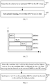
FIG. 1 is a flowchart of a method of triggering BWP handover according to an exemplary embodiment of the present disclosure. -
FIG. 2 is a schematic diagram of WUSs on different BWPs according to an exemplary embodiment of the present disclosure. -
FIG. 3 is a flowchart of an information configuring method according to an exemplary embodiment of the present disclosure. -
FIG. 4 is a signaling flowchart of a method of triggering BWP handover according to an exemplary embodiment of the present disclosure. -
FIG. 5 is a block diagram of an apparatus for triggering BWP handover according to an exemplary embodiment. -
FIG. 6 is a block diagram of another apparatus for triggering BWP handover according to an exemplary embodiment. -
FIG. 7 is a block diagram of another apparatus for triggering BWP handover according to an exemplary embodiment. -
FIG. 8 is a block diagram of another apparatus for triggering BWP handover according to an exemplary embodiment. -
FIG. 9 is a block diagram of another triggering apparatus for triggering BWP handover according to an exemplary embodiment. -
FIG. 10 is a block diagram of an information configuring apparatus according to an exemplary embodiment. -
FIG. 11 is a block diagram of another information configuring apparatus according to an exemplary embodiment. -
FIG. 12 is a block diagram of another information configuring apparatus according to an exemplary embodiment -
FIG. 13 is a block diagram of another information configuring apparatus according to an exemplary embodiment -
FIG. 14 is a block diagram applicable to an apparatus for triggering BWP handover according to an exemplary embodiment. -
FIG. 15 is a block diagram applicable to an information configuring apparatus according to an exemplary embodiment. - Exemplary embodiments will be described in detail herein, examples of which are shown in the accompanying drawings. The following description relates to the drawings, unless otherwise indicated, the same numerals in the different figures represent the same or similar elements. The embodiments described in the following exemplary embodiments do not represent all embodiments consistent with the present disclosure. Rather, they are merely examples of devices and methods consistent with some aspects of the disclosure as detailed in the appended claims.
-
FIG. 1 is a flowchart of a method of triggering BWP handover according to an exemplary embodiment of the present disclosure, and the embodiment is described from a UE side. As shown inFIG. 1 , the method of triggering BWP handover includes the following steps. - In step S 101, it is detected that the channel on an activated BWP for the UE is busy.
- In this embodiment, the UE may monitor a pre-set signal within a pre-set signal monitoring time window configured for the activated BWP by the base station. If none of the pre-set signal is monitored, it indicates that the base station detects that the channel is busy on the activated BWP for the UE and thus the pre-set signal cannot be sent; If the pre-set signal is monitored, it indicates that the base station detects that the channel is idle on the activated BWP for the UE and thus the pre-set signal is sent.
- The pre-set signal may include, but is not limited to, a wake up signal (WUS), an initial signal, or a similar wireless fidelity (WIFI) preamble signal, which is used to indicate that the base station detects that the channel on the activated BWP for the UE is idle, wherein the initial signal may include, but is not limited to, a primary synchronization signal (PSS) or a secondary synchronization signal (SSS). The pre-set signal may carry, but is not limited to, at least one of a cell identifier, a BWP identifier, or a UE group identifier to which a respective BWP belongs. The purpose of sending the pre-set signal is to inform the UE that the base station detects that the channel on the BWP is idle, and then the base station will send downlink control signaling on the PDCCH of the BWP. After detecting the pre-set signal, the UE needs to monitor, on the BWP, the downlink control signaling on the PDCCH to obtain uplink and downlink scheduling information sent by the base station.
- In
step S 102, automatic handover to other BWP is performed to receive data. - In this embodiment, the UE may determine a candidate BWP with the idle channel and the highest priority from the candidate BWP(s) configured by the base station, and hand over to the candidate BWP with the idle channel and the highest priority to receive data.
- In addition to configuring the activated BWP for the UE, the base station further configures one or more candidate BWPs, and the activated BWP and each of the candidate BWPs have priorities. For example, the priority of the activated BWP is the highest, and the priorities of other candidate BWPs are different. For example, the activated BWP is
BWP# 0, the other candidate BWPs areBWP# 1 andBWP# 2, and the priority order thereof isBWP# 0 >BWP# 1 >BWP# 2. Furthermore, the base station sets a signal monitoring time window for each BWP, and the UE needs to monitor the pre-set signal on each BWP in the monitoring time window of each BWP. There may be a time interval between the pre-set signals on different BWPs for the BWP handover of the UE, such that the UE only needs to monitor one BWP at the same time, that is, the receiving bandwidth is small and power is saved. There may be no time interval or be overlap time between the pre-set signals on different BWPs, such that the UE needs to monitor a plurality of BWPs at the same time, that is, the receiving bandwidth thereof needs to be increased, and power is consumed. When the pre-set signal is WUS, as shown inFIG. 2 , the cell or carrier bandwidth is 80 MHz, and includes four BWPs in total fromBWP# 0 to BWP#3, whereBWP# 0 is an activated BWP,BWP# 1 to BWP#3 are candidate BWPs, and there are time intervals among WUSs on different BWPs. - Optionally, the UE may receive the configuration information of the candidate BWP(s) and the configuration information of the activated BWP sent by the base station, and the base station may set the priority and the signal monitoring time window for the candidate BWP(s) and the activated BWP.
- It should be noted that the transmission order of the pre-set signal, e.g., WUS, of each BWP is not directly related to the priority of each BWP. For example, for
UE# 1, the currently activated BWP isBWP# 0, other candidate BWPs areBWP# 1 andBWP# 2, and the priority order thereof isBWP# 0 >BWP# 1 >BWP# 2, and the transmission order of the WUS is also in an order ofBWP# 0 earlier thanBWP# 1 andBWP# 1 earlier thanBWP# 2. However, forUE# 2, it is possible that the currently activated BWP isBWP# 1, the candidate BWPs areBWP# 2 and BWP#4, the priority order isBWP# 1 > BWP#4 >BWP# 2, and the transmission order of the WUS is in an order ofBWP# 1 earlier thanBWP# 2 andBWP# 2 earlier than BWP#4. - In this embodiment, determining the candidate BWP with the idle channel and the highest priority from the candidate BWP(s) configured by the base station may include: monitoring a pre-set signal within the pre-set signal monitoring time window corresponding to each candidate BWP, and if the pre-set signal is monitored, it indicates that the idle channel on a corresponding candidate BWP is idle, selecting a candidate BWP with an idle channel and a highest priority from the candidate BWP(s) configured by the base station.
- As an example, if a pre-set signal is monitored within the pre-set signal monitoring time window corresponding to the candidate BWP with the highest priority, the candidate BWP with the highest priority is determined as the candidate BWP with the idle channel and the highest priority, that is, when detecting that the channel of the candidate BWP with the highest priority is idle, the other candidate BWP is unnecessary to be detected. As another example, if a pre-set signal is monitored within the pre-set signal monitoring time windows of respective candidate BWPs, a candidate BWP with the highest priority is determined from the candidate BWPs which have monitored the pre-set signal, and a candidate BWP with the highest priority is taken as a candidate BWP with the idle channel and the highest priority, that is, when it is detected that BWP channels are idle, a candidate BWP with the highest priority is selected.
- In this embodiment, if the UE detects a pre-set signal, such as WUS, on a BWP with a high priority, it is unnecessary to detect whether WUS exists on a BWP with a low priority. In this embodiment, it is also possible to monitor WUS on the BWP with the low priority first. When pre-set signals such as WUSs on idle channels of BWPs are monitored, the UE needs to be handed over to the candidate BWP with the highest priority of the idle channel to receive data from the base station to itself, for example, downlink control signaling on the PDCCH is received in a control resource set (CORESET for short). After receiving the downlink control signaling on the PDCCH, physical downlink shared channel (PDSCH) reception or physical uplink shared channel (PUSCH) transmission is performed according to information such as time-frequency resources indicated by the downlink control signaling. That is to say, the activated BWP for the UE has been handed over to the candidate BWP with the idle channel and the highest priority.
- In the above embodiments, by detecting that the channel on the activated BWP for the UE is busy and automatically handing over to other BWP to receive data, load balancing may be performed between different BWPs to ensure that the service of the UE may be processed in time.
-
FIG. 3 is a flowchart of an information configuring method according to an exemplary embodiment of the present disclosure, and the embodiment is described from a base station side. As shown inFIG. 3 , the method includes the following steps. - In step S301, when detecting that the channel on the activated BWP for the UE is busy, the candidate BWP with the idle channel and the highest priority is selected from the candidate BWP configured for the UE.
- The base station configures a plurality of BWPs for the UE, including information such as a BWP identifier (ID), a frequency domain resource, and the priority of each BWP. However, among the plurality of BWPs, the
BWP# 1 may be configured as an activated BWP by the base station, and the other BWPs may be candidate BWPs with respect to the activated the BWP. - In step S302, data, via the candidate BWP in which the channel is idle and has the highest priority, is sent to the UE.
- Optionally, after determining that the BWP is activated, if the base station detects that the channel on the activated BWP for the UE is idle, the base station may also send a pre-set signal via the activated BWP to indicate that the channel on the activated BWP for the UE is idle.
- In this embodiment, when detecting that the channel on the activated BWP for the UE is idle, the base station sends a pre-set signal first to indicate that the channel is idle. Then, when monitoring the pre-set signal in the configured pre-set signal monitoring time window, the UE knows that the channel is idle, and detects the PDCCH in the next CORESET. If none of the pre-set signal is monitored within the configured pre-set signal monitoring time window, which means that the channel is busy, it is unnecessary to detect the next signal.
- In addition, optionally, the method may further include: an activated BWP and a candidate BWP are configured for the UE, a priority and a signal monitoring time window are set for the candidate BWP and the activated BWP, and configuration information, configuration information of the candidate BWP, and a priority and a pre-set signal monitoring time window set for the candidate BWP and the activated BWP are sent to UE.
- In this embodiment, in addition to configuring the UE with the activated BWP, the base station further configures one or more candidate BWPs, and the activated BWP and each of the candidate BWPs have priorities, for example, the priority of the activated BWP is the highest, and the priorities of other candidate BWPs are different. For example, the activated BWP is
BWP# 0, the other candidate BWPs areBWP# 1 andBWP# 2, and the priority order thereof isBWP# 0 >BWP# 1 >BWP# 2. Furthermore, the base station sets a signal monitoring time window for each BWP, and the UE needs to monitor the pre-set signal on each BWP in the monitoring time window of each BWP. A time interval may exist between the pre-set signals on different BWPs for the BWP handover of the UE, such that the UE only needs to monitor one BWP at the same time, that is, the receiving bandwidth is small, and power is saved. There may be no time interval or be overlap time between the pre-set signals on different BWPs, such that the UE needs to monitor a plurality of BWPs at the same time, that is, the receiving bandwidth thereof needs to be increased, and power is consumed. When the pre-set signal is WUS, as shown inFIG. 2 , the cell or carrier bandwidth is 80 MHz, and includes four BWPs in total fromBWP# 0 to BWP#3, whereBWP# 0 is an activated BWP,BWP# 1 to BWP#3 are candidate BWPs, and there are time intervals among WUSs on different BWPs. - In this embodiment, the base station detects that the channel on the activated BWP for the UE is busy, the method may further include: detecting whether a channel on each candidate BWP is idle; and sending the pre-set signal via the candidate BWP of the idle channel, such that the UE monitors the pre-set signal within the pre-set signal monitoring time window corresponding to each candidate BWP. If the pre-set signal is monitored, it indicates that the channel on the corresponding candidate BWP is idle, such that the UE selects a candidate BWP with the idle channel and the highest priority from the candidate BWP(s) configured by the base station.
- In this embodiment, when detecting that the channel on the activated BWP for the UE is busy, the base station selects a candidate BWP with the idle channel and the highest priority from the candidate BWPs configured for the UE; and send data to the UE on the BWP with the idle channel and the highest priority. For example, the downlink control signaling of the UE is sent on the PDCCH in the CORESET of the candidate BWP with the highest priority and the idle channel. The downlink control signaling is used to instruct the base station to schedule time-frequency resources for PDSCH reception or PUSCH transmission to the UE.
- In this embodiment, the priority of each BWP is set in order to make the behavior of the base station and the UE uniform. If the channels on the candidate BWPs are idle, among the candidate BWPs with the idle channels, the base station selects a candidate BWP with the highest priority to send data of the UE. For example, the downlink control signaling of the UE is sent on the PDCCH in the CORESET of the candidate BWP with the highest priority and the idle channel. The downlink control signaling is used to instruct the base station to schedule time-frequency resources for PDSCH reception or PUSCH transmission to the UE. The UE also needs to receive the downlink control signaling on its own PDCCH in the CORESET on the candidate BWP with the highest priority and idle channel according to the condition of the monitoring pre-set signal such as WUS. After receiving the downlink control signaling on the PDCCH, the UE performs PDSCH reception or PUSCH transmission according to information such as time-frequency resources indicated by the downlink control signaling. The priority of the activated BWP is higher than the priorities of all candidate BWPs.
- In the above embodiment, the channel on the activated BWP for the UE is detected to be busy, and the candidate BWP with the idle channel and the highest priority is selected from the candidate BWP of the UE and data is sent to the UE via the selected candidate BWP with the idle channel and the highest priority. Thus, the UE may detect that the channel on its activated BWP is busy, and automatically hand over to other BWP to receive data, thereby ensuring that its service may be processed in time.
-
FIG. 4 is a signaling flowchart of a method of triggering BWP handover according to an exemplary embodiment of the present disclosure, and the embodiment is described from the perspective of interaction between a base station and a UE. As shown inFIG. 4 , the method includes the following steps. - In step S401, the base station detects that the channel on the activated BWP for the UE is busy, and selects a candidate BWP with the idle channel and the highest priority from the one or more candidate BWPs configured for the UE.
- In step S402, the base station sends data to the UE via the candidate BWP with the idle channel and the highest priority.
- In step S403, the UE detects that the channel on the activated BWP for the UE is busy.
- In step S404, the UE automatically hands over to other BWP to receive data.
- In the foregoing embodiment, through interaction between the base station and the UE, the UE automatically hands over to other BWP to receive data when detecting that the channel on its activated BWP is busy, such that load balancing may be performed between different BWPs and the service of the UE may be processed in time.
-
FIG. 5 is a block diagram of an apparatus for triggering BWP handover according to an exemplary embodiment. The apparatus may be located in a UE, as shown inFIG. 5 . The apparatus includes a detectingmodule 51 and ahandover module 52. - The detecting
module 51 is configured to detect whether a channel on the activated BWP for the UE is busy. - In this embodiment, the UE may monitor the pre-set signal within the pre-set signal monitoring time window configured for the activated BWP by the base station. If none of the pre-set signal is monitored, it indicates that the base station detects that the channel is busy on the activated BWP for the UE, and thus the pre-set signal cannot be sent; if the pre-set signal is monitored, it indicates that the base station detects that the channel is idle on the activated BWP for the UE, and thus the pre-set signal is sent.
- The pre-set signal may include, but is not limited to, a wake up signal (WUS), an initial signal, or a similar wireless fidelity (WIFI) preamble signal, which is used to indicate that the base station detects that the channel on the activated BWP for the UE is idle, wherein the initial signal may include, but is not limited to, a primary synchronization signal (PSS) or a secondary synchronization signal (SSS). The pre-set signal may carry, but is not limited to, at least one of a cell identifier, a BWP identifier, and a UE group identifier to which a respective BWP belongs. The purpose of sending the pre-set signal is to inform the UE that the base station detects that the channel on the BWP is idle, and then the base station will send downlink control signaling on the PDCCH of the BWP. After detecting the pre-set signal, the UE needs to monitor, on the BWP, the downlink control signaling on the PDCCH to obtain uplink and downlink scheduling information sent by the base station.
- The
handover module 52 is configured to automatically hand over to other BWP to receive data when the detectingmodule 51 detects that the channel on the activated BWP for the UE is busy. - In this embodiment, the UE may determine the candidate BWP with the idle channel and the highest priority from the candidate BWP(s) configured by the base station, and hand over to the candidate BWP with the idle channel and the highest priority to receive data.
- In addition to configuring the activated BWP for the UE, the base station further configures one or more candidate BWPs, and the activated BWP and each of the candidate BWPs have priorities. For example, the priority of the activated BWP is the highest, and the priorities of other candidate BWPs are different. For example, the activated BWP is
BWP# 0, the other candidate BWPs areBWP# 1 andBWP# 2, and the priority order thereof isBWP# 0 >BWP# 1 >BWP# 2. Furthermore, the base station sets a signal monitoring time window for each BWP, and the UE needs to monitor the pre-set signal on each BWP in the monitoring time window of each BWP. There may be a time interval between the pre-set signals on different BWPs for the BWP handover of the UE, such that the UE only needs to monitor one BWP at the same time, that is, the receiving bandwidth is small and power is saved. There may be no time interval or be overlap time between the pre-set signals on different BWPs, such that the UE needs to monitor a plurality of BWPs at the same time, that is, the receiving bandwidth thereof needs to be increased, and power is consumed. When the pre-set signal is WUS, as shown inFIG. 2 , the cell or carrier bandwidth is 80 MHz, and includes four BWPs in total fromBWP# 0 to BWP#3, whereBWP# 0 is an activated BWP,BWP# 1 to BWP#3 are candidate BWPs, and there are time intervals among WUSs on different BWPs. - Optionally, the UE may receive the configuration information of the candidate BWP(s) and the configuration information of the activated BWP sent by the base station, and the base station may set the priority and the signal monitoring time window for the candidate BWP(s) and the activated BWP.
- It should be noted that the transmission order of the pre-set signal, e.g., WUS, of each BWP is not directly related to the priority of each BWP. For example, for
UE# 1, the currently activated BWP isBWP# 0, other candidate BWPs areBWP# 1 andBWP# 2, and the priority order thereof isBWP# 0 >BWP# 1 >BWP# 2, and the transmission order of the WUS is also in an order ofBWP# 0 earlier thanBWP# 1 andBWP# 1 earlier thanBWP# 2. However, forUE# 2, it is possible that the currently activated BWP isBWP# 1, the candidate BWPs areBWP# 2 and BWP#4, the priority order isBWP# 1 > BWP#4 >BWP# 2, and the transmission order of the WUS is in an order ofBWP# 1 earlier thanBWP# 2 andBWP# 2 earlier than BWP#4. - In this embodiment, determining the candidate BWP with idle channel and the highest priority from the candidate BWP(s) configured by the base station may include: monitoring the pre-set signal within the pre-set signal monitoring time window corresponding to each candidate BWP, and if the pre-set signal is monitored, it indicates that the idle channel on a corresponding candidate BWP is idle, selecting a candidate BWP with an idle channel and a highest priority from the candidate BWP(s) configured by the base station.
- As an example, if the pre-set signal is monitored within the pre-set signal monitoring time window corresponding to the candidate BWP with the highest priority, the candidate BWP with the highest priority is determined as the candidate BWP with the idle channel and the highest priority, i.e., when detecting that the channel of the candidate BWP with the highest priority is idle, the other candidate BWP is unnecessary to be detected. As another example, if a pre-set signal is monitored within the pre-set signal monitoring time windows of respective candidate BWPs, a candidate BWP with the highest priority is determined from the candidate BWPs which have monitored the pre-set signal, and a candidate BWP with the highest priority is taken as a candidate BWP with the idle channel and the highest priority, that is, when it is detected that BWP channels are idle, a candidate BWP with the highest priority is selected.
- In this embodiment, if the UE detects a pre-set signal, such as WUS, on a BWP with a high priority, it is unnecessary to detect whether WUS exists on a BWP with a low priority. In this embodiment, it is also possible to monitor WUS on the BWP with the low priority first. When pre-set signals such as WUSs on idle channels of BWPs are monitored, the UE needs to hand over to the candidate BWP with the highest priority of the idle channel to receive data by itself from the base station, for example, downlink control signaling on the PDCCH is received in a control resource set (CORESET for short). After receiving the downlink control signaling on the PDCCH, physical downlink shared channel (PDSCH) reception or physical uplink shared channel (PUSCH) transmission is performed according to information such as time-frequency resources indicated by the downlink control signaling. That is to say, the activated BWP for the UE has been handed over to the candidate BWP with the idle channel and the highest priority.
- In the above embodiments, by detecting that the channel on the activated BWP for the UE is busy and automatically handing over to other BWP to receive data, load balancing may be performed between different BWPs to ensure that the service of the UE may be processed in time.
-
FIG. 6 is a block diagram of another apparatus for triggering BWP handover according to an exemplary embodiment. As shown inFIG. 6 , on the basis of the embodiment shown inFIG. 5 , the detectingmodule 51 may include the following sub-modules. - A
monitoring sub-module 511 is configured to monitor a pre-set signal within a pre-set signal monitoring time window configured for the activated BWP by a base station. - A detecting
sub-module 512 is configured to detect that the channel on the activated BWP for the UE is busy if themonitoring sub-module 511 does not monitor the pre-set signal. - In the above embodiments, the pre-set signal is monitored within the pre-set signal monitoring time window configured for the activated BWP by the base station, and when none of the pre-set signal is monitored, the channel on the activated BWP for the UE is detected to be busy, in such a way that the implementation is simple.
-
FIG. 7 is a block diagram of another apparatus for triggering BWP handover according to an exemplary embodiment. As shown inFIG. 7 , on the basis of the embodiment shown inFIG. 5 , thehandover module 52 may include the following sub-modules. - A determining
sub-module 521 is configured to determine a candidate BWP with the idle channel and the highest priority from one or more candidate BWPs configured by the base station. - A
handover sub-module 522 is configured to hand over to the candidate BWP with the idle channel and the highest priority determined by the determining sub-module 521 to receive data. - In the above embodiment, the candidate BWP with the idle channel and the highest priority is determined, and data is received by handing over to the determined candidate BWP with the idle channel and the highest priority, thereby ensuring that its own service may be processed in time.
-
FIG. 8 is a block diagram of another apparatus for triggering BWP handover according to an exemplary embodiment. As shown inFIG. 8 , on the basis of the embodiment shown inFIG. 7 , the apparatus may further include a receivingmodule 50. - The receiving
module 50 is configured to receive configuration information of the candidate BWPs and configuration information of the activated BWP from the base station, and receive a priority and a pre-set signal monitoring time window set by the base station for the candidate BWPs and the activated BWP respectively. - In the above embodiment, by receiving configuration information of the candidate BWPs and configuration information of the activated BWP from the base station, and receiving a priority and a pre-set signal monitoring time window set by the base station for the candidate BWPs and the activated BWP respectively, in a such way that a condition is provided for subsequently detecting whether the channel on the BWP is busy.
-
FIG. 9 is a block diagram of another triggering apparatus for triggering BWP handover according to an exemplary embodiment. As shown inFIG. 9 , on the basis of the embodiment shown inFIG. 8 , the determining sub-module 521 may include the following units. - A
monitoring unit 5211 is configured to, for each of the candidate BWPs, monitor a pre-set signal within the pre-set signal monitoring time window corresponding to the candidate BWP, and detecting that a channel on the candidate BWP is idle when the pre-set signal is monitored. - A selecting
unit 5212 is configured to select a candidate BWP with the idle channel and a highest priority from the candidate BWPs configured by the base station. - In the foregoing embodiment, by selecting a candidate BWP with the idle channel and the highest priority, a condition is provided for subsequently automatically handing over to receive data via the candidate BWP.
-
FIG. 10 is a block diagram of an information configuring apparatus according to an exemplary embodiment. The apparatus may be located in a base station, as shown inFIG. 10 , the apparatus includes adetection selecting module 110 and afirst sending module 120. - The
detection selecting module 110 is configured to, when detecting that a channel on an activated bandwidth part BWP of user equipment (UE) is busy, a candidate BWP with an idle channel and a highest priority from one or more candidate BWPs configured for the UE. - The base station configures a plurality of BWPs for the UE, including information such as a BWP identifier (ID), a frequency domain resource, and the priority of each BWP. However, among the plurality of BWPs, the
BWP# 1 may be configured as an activated BWP by the base station, and the other BWPs may be candidate BWPs with respect to the activated BWP. - The
first transmission module 120 is configured to send data to the UE via the candidate BWP with the idle channel and the highest priority selected by thedetection selecting module 110. - In the above embodiment, by determining the activated BWP and sending the configuration information for the activated BWP to the UE, the UE may automatically hand over to other BWP to receive data when detecting that the channel on the activated BWP is busy, thereby ensuring that the service of the UE may be processed in time.
-
FIG. 11 is a block diagram of another information configuring apparatus according to an exemplary embodiment. As shown inFIG. 11 , on the basis of the embodiment shown inFIG. 10 , the apparatus may further include a second sending module. - The
second sending module 130 is configured to send a pre-set signal via the activated BWP when detecting that the channel on the activated BWP is idle. - After determining the activated BWP, if the base station detects that the channel on the activated BWP for the UE is idle, the base station may also send a set signal via the activated BWP to indicate that the channel on the activated BWP for the UE is idle.
- In the above embodiment, the UE detects whether the channel for the activated BWP is idle by sending the pre-set signal via the activated BWP.
-
FIG. 12 is a block diagram of another information configuring apparatus according to an exemplary embodiment. As shown inFIG. 12 , on the basis of the embodiment shown inFIG. 10 or FIG. 11 , the apparatus may further include the following modules. - A
configuration module 140 is configured to configure the activated BWP and the candidate BWPs for the UE, and set a priority and a pre-set signal monitoring time window for the candidate BWPs and the activated BWP respectively. - A
third sending module 150 is configured to send configuration information of the activated BWP, configuration information of the candidate BWPs, and the priority and the pre-set signal monitoring time window set for the candidate BWPs and the activated BWP to the UE. - In the foregoing embodiment, the activated BWP and the candidate BWP are configured for the UE, and the priority and the set signal monitoring time window are set for the candidate BWP and the activated BWP, and then the configuration information of the activated BWP, the configuration information of the candidate BWP and the priority and the set signal monitoring time window configured by the
configuration module 140 are sent to the UE, which facilitates the UE to detects whether the channel on the BWP is idle. -
FIG. 13 is a block diagram of another information configuring apparatus according to an exemplary embodiment. As shown inFIG. 13 , on the basis of the embodiment shown inFIG. 12 , the apparatus may further include a detectingmodule 160 and afourth sending module 170. - The detecting
module 160 is configured to detect, for each of the candidate BWPs, whether a channel on the candidate BWP is idle. - The
fourth sending module 170 is configured to send a pre-set signal via the candidate BWP of the idle channel detected by the detectingmodule 160. - In this embodiment, if there are idle channels on the BWPs, the base station selects a BWP with the highest priority from the idle BWPs to send data of the UE.
- In the above embodiment, the data of the UE is sent over the determined channel of the candidate BWP with the highest priority, such that the base station and the terminal achieves consensus, that is, the base station sends data associated with the UE on the BWP with the idle channel and the highest priority, such as PDCCH, and the UE also knows that the signal is received on the BWP with the idle channel and the highest priority, such as the signal on the PDCCH.
-
FIG. 14 is a block diagram applicable to an apparatus for triggering BWP handover according to an exemplary embodiment. For example, theapparatus 1400 may include user equipment such as mobile phones, computers, digital broadcasted terminals, message transceivers, game consoles, tablet devices, medical devices, fitness devices and personal digital assistants. - Referring to
FIG. 14 , theapparatus 1400 may include one or more of the following components: aprocessing component 1402, amemory 1404, apower supply component 1406, amultimedia component 1408, anaudio component 1410, an input/output (I/O)interface 1412, asensor component 1414, and acommunication component 1416. - The
processing component 1402 generally controls overall operations of theapparatus 1400, such as operations associated with display, phone calls, data communications, camera operations, and recording operations. Theprocessing component 1402 may include one ormore processors 1420 to execute instructions to implement all or part of the steps of the above method embodiments implemented by UE 20. In addition, theprocessing component 1402 may include one or more modules which facilitate the interaction between theprocessing component 1402 and other components. For example, theprocessing component 1402 may include a multimedia module to facilitate the interaction between themultimedia component 1408 and theprocessing component 1402. - One of the
processors 1420 in theprocessing component 1402 may be configured to: - detect channel busy on the activated BWP for the UE, and
- automatically hand over to other BWP to receive data.
- The
memory 1404 is configured to store various types of data to support the operation of theapparatus 1400. Examples of such data include instructions for any application or method operated on theapparatus 1400, contact data, phonebook data, messages, pictures, videos, and so on. Thememory 1404 may be implemented by any type of volatile or non-volatile storage devices or a combination thereof, such as a Static Random-Access Memory (SRAM), an Electrically Erasable Programmable Read-Only Memory (EEPROM), an Erasable Programmable Read-Only Memory (EPROM), a Programmable Read-Only Memory (PROM), a Read-Only Memory (ROM), a magnetic memory, a flash memory, a magnetic or optical disk. - The
power supply component 1406 provides power to different components of theapparatus 1400. Thepower supply component 1406 may include a power management system, one or more power supplies, and other components associated with generating, managing, and distributing power for theapparatus 1400. - The
multimedia component 1408 includes a screen providing an output interface between theapparatus 1400 and a user. In some examples, the screen may include a Liquid Crystal Display (LCD) and a Touch Panel (TP). If the screen includes the TP, the screen may be implemented as a touch screen to receive input signals from the user. The TP may include one or more touch sensors to sense touches, swipes, and gestures on the TP. The touch sensors may not only sense a boundary of a touch or swipe, but also sense a duration and a pressure associated with the touch or swipe. In some examples, themultimedia component 1408 may include a front camera and/or a rear camera. The front camera and/or rear camera may receive external multimedia data when theapparatus 1400 is in an operating mode, such as a photographing mode or a video mode. Each of the front camera and the rear camera may be a fixed optical lens system or have focal length and optical zooming capability. - The
audio component 1410 is configured to output and/or input an audio signal. For example, theaudio component 1410 includes a microphone (MIC). When theapparatus 1400 is in an operating mode, such as a call mode, a recording mode, and a voice recognition mode, the MIC is configured to receive an external audio signal. The received audio signal may be further stored in thememory 1404 or sent via thecommunication component 1416. In some examples, theaudio component 1410 further includes a speaker to output an audio signal. - The I/
O interface 1412 may provide an interface between theprocessing component 1402 and peripheral interface modules. The above peripheral interface modules may include a keyboard, a click wheel, buttons and so on. These buttons may include, but are not limited to, a home button, a volume button, a starting button and a locking button. - The
sensor component 1414 includes one or more sensors to provide status assessments of various aspects for theapparatus 1400. For example, thesensor component 1414 may detect the on/off status of theapparatus 1400, and relative positioning of component, for example, the component is a display and a keypad of theapparatus 1400. Thesensor component 1414 may also detect a change in position of theapparatus 1400 or a component of theapparatus 1400, a presence or absence of the contact between a user and theapparatus 1400, an orientation or an acceleration/deceleration of theapparatus 1400, and a change in temperature of theapparatus 1400. Thesensor component 1414 may include a proximity sensor to detect the presence of a nearby object without any physical contact. Thesensor component 1414 may further include an optical sensor, such as a Complementary Metal-Oxide-Semiconductor (CMOS) or Charged Coupled Device (CCD) image sensor which is used in imaging applications. In some examples, thesensor component 1414 may further include an acceleration sensor, a gyroscope sensor, a magnetic sensor, a pressure sensor, or a temperature sensor. - The
communication component 1416 is configured to facilitate wired or wireless communication between theapparatus 1400 and other devices. Theapparatus 1400 may access a wireless network that is based on a communication standard, such as Wi-Fi, 2G or 3G, or a combination thereof. In an example, thecommunication component 1416 receives a broadcasted signal or broadcast-associated information from an external broadcasted management system via a broadcasted channel. In an example, thecommunication component 1416 further includes a Near Field Communication (NFC) module to facilitate short-range communications. For example, the NFC module may be implemented based on a Radio Frequency Identification (RFID) technology, an Infrared Data Association (IrDA) technology, an Ultra-Wideband (UWB) technology, a Bluetooth® (BT) technology and other technologies. - In an example, the
apparatus 1400 may be implemented by one or more Application Specific Integrated Circuits (ASIC), Digital Signal Processors (DSP), Digital Signal Processing Devices (DSPD), programmable Logic Devices (PLD), Field Programmable Gate Arrays (FPGA), controllers, microcontrollers, microprocessors, or other electronic components for performing the above method. - In an example, there is also provided a non-transitory machine-readable storage medium including instructions, such as a
memory 1404 including instructions. The above instructions may be executed by theprocessor 1420 of theapparatus 1400 to perform the above methods embodiments implemented by UE 20. For example, the non-transitory machine-readable storage media may include a Read-Only Memory (ROM), a Random-Access Memory (RAM), a Compact disc ROM (CD-ROM), a magnetic tape, a floppy disk, an optical data storage device and so on. -
FIG. 15 is a block diagram applicable to an information configuring apparatus according to an exemplary embodiment. Theapparatus 1500 may be provided as a base station. Referring toFIG. 15 , theapparatus 1500 includes aprocessing component 1522, a wireless transmit/receivecomponent 1524, anantenna component 1526, and a wireless interface-specific signal processing portion, and theprocessing component 1522 may further include one or more processors. - One of the processors in the
processing component 1522 may be configured to: - select, when detecting that a channel on an activated bandwidth part BWP of user equipment (UE) is busy, a candidate BWP with an idle channel and a highest priority from one or more candidate BWPs configured for the UE; and
- send, via the selected candidate BWP with the idle channel and the highest priority, data to the UE.
- In an exemplary embodiment, a non-transitory computer-readable storage medium is also provided, which includes instructions executed by the
processing component 1522 of theapparatus 1500 to implement the information configuring method. For example, the non-transitory computer-readable storage medium may be a ROM, a random access memory (RAM), a CD-ROM, a magnetic tape, a floppy disk, an optical data storage device, and the like. - Since the device examples substantially correspond to the method examples, a reference may be made to part of the descriptions of the method examples for the related part. The device examples described above are merely illustrative, where the units described as separate members may be or not be physically separated, and the members displayed as units may be or not be physical units, i.e., may be located in one place, or may be distributed to a plurality of network units. Part or all of the modules may be selected according to actual requirements to implement the objectives of the solutions in the examples. Those of ordinary skill in the art may understand and carry out them without creative work.
- It shall be noted that the relational terms such as "first" and "second" used herein are merely intended to distinguish one entity or operation from another entity or operation rather than to require or imply any such actual relation or order existing between these entities or operations. Also, the term "including", "containing" or any variation thereof is intended to encompass non-exclusive inclusion, such that a process, method, article or device including a series of elements includes not only those elements but also other elements not listed explicitly or those elements inherent to such a process, method, article or device. Without more limitations, an element defined by the statement "including a..." shall not be precluded to include additional same elements present in a process, method, article or device including the elements.
- Other implementations of the present disclosure will be apparent to those skilled in the art from consideration of the specification and practice of the present disclosure herein. The present disclosure is intended to cover any variations, uses, modification or adaptations of the present disclosure that follow the general principles thereof and include common knowledge or conventional technical means in the art that are not disclosed in the present disclosure. The specification and examples are considered as exemplary only, with a true scope and spirit of the present disclosure being indicated by the following claims.
- It is to be understood that the present disclosure is not limited to the precise structure described above and shown in the accompanying drawings, and that various modifications and changes may be made without departing from the scope thereof. The scope of the present disclosure is limited only by the appended claims.
Claims (26)
- A method of triggering a bandwidth part (BWP) handover, applicable to user equipment (UE), the method comprising:detecting that a channel on an activated BWP for the UE is busy; andautomatically handing over to other BWP to receive data.
- The method according to claim 1, wherein detecting that the channel on the activated BWP for the UE is busy comprises:monitoring a pre-set signal within a pre-set signal monitoring time window configured for the activated BWP by a base station; anddetecting that the channel on the activated BWP for the UE is busy when none of the pre-set signal is monitored.
- The method according to claim 1, wherein automatically handing over to other BWP to receive data comprises:determining a candidate BWP with an idle channel and a highest priority from one or more candidate BWPs configured by a base station; andhanding over to the determined candidate BWP with the idle channel and the highest priority to receive data.
- The method according to claim 2 or 3, further comprising:receiving configuration information of the candidate BWPs and configuration information of the activated BWP from the base station, andreceiving a priority and a pre-set signal monitoring time window set by the base station for the candidate BWPs and the activated BWP respectively.
- The method according to claim 4, wherein determining the candidate BWP with the idle channel and the highest priority from the one or more candidate BWPs configured by the base station comprises:for each of the candidate BWPs,monitoring a pre-set signal within the pre-set signal monitoring time window corresponding to the candidate BWP, anddetecting that a channel on the candidate BWP is idle when the pre-set signal is monitored; andselecting a candidate BWP with the idle channel and a highest priority from the candidate BWPs configured by the base station.
- The method according to claim 2 or 5, whereinthe pre-set signal comprises a wake-up signal (WUS) or an initial signal, andthe pre-set signal carries at least one of a cell identifier, a BWP identifier or a UE group identifier to which a respective BWP belongs.
- An information configuring method, applicable to a base station, comprising:selecting, when detecting that a channel on an activated bandwidth part (BWP) for user equipment (UE) is busy, a candidate BWP with an idle channel and a highest priority from one or more candidate BWPs configured for the UE; andsending, via the selected candidate BWP with the idle channel and the highest priority, data to the UE.
- The method according to claim 7, further comprising:sending, when detecting that the channel on the activated BWP is idle, a pre-set signal via the activated BWP.
- The method according to claim 7 or 8, further comprising:configuring the activated BWP and the candidate BWPs for the UE,pre-set a priority and a pre-set signal monitoring time window for the candidate BWPs and the activated BWP respectively; andsending, to the UE, configuration information of the activated BWP, configuration information of the candidate BWPs, and the priority and the pre-set signal monitoring time window set for the candidate BWPs and the activated BWP.
- The method according to claim 9, further comprising:detecting, for each of the candidate BWPs, whether a channel on the candidate BWP is idle; andsending a pre-set signal via the candidate BWP of the idle channel.
- The method according to claim 8 or 10, whereinthe pre-set signal comprises a wake-up signal (WUS) or an initial signal, andthe pre-set signal carries at least one of a cell identifier, a BWP identifier or a UE group identifier to which a respective BWP belongs.
- An apparatus for triggering a bandwidth part (BWP) handing over, applicable to user equipment (UE), comprising:a detecting module, configured to detect whether a channel on an activated BWP for the UE is busy; anda handover module, configured to automatically hand over to other BWP to receive data when the detecting module detects that the channel on the activated BWP for the UE is busy.
- The apparatus according to claim 12, wherein the detecting module comprises:a monitoring sub-module, configured to monitor a pre-set signal within a pre-set signal monitoring time window configured for the activated BWP by a base station; anda detecting sub-module, configured to detect that the channel on the activated BWP for the UE is busy when none of the pre-set signal is monitored by the monitoring sub-module.
- The apparatus according to claim 12, wherein the handover module comprises:a determining sub-module, configured to determine a candidate BWP with an idle channel and a highest priority from one or more candidate BWPs configured by a base station; anda handover sub-module, configured to hand over to the candidate BWP with the idle channel and the highest priority determined by the determining sub-module to receive data.
- The apparatus according to claim 13 or 14, further comprising:a receiving module, configured to receive configuration information of the candidate BWPs and configuration information of the activated BWP from the base station, and receive a priority and a pre-set signal monitoring time window set by the base station for the candidate BWPs and the activated BWP respectively .
- The apparatus according to claim 15, wherein the determining sub-module comprises:a monitoring unit, configured to, for each of the candidate BWPs, monitor a pre-set signal within the pre-set signal monitoring time window corresponding to the candidate BWP, and detect that a channel on the candidate BWP is idle when the pre-set signal is monitored; anda selecting unit, configured to select a candidate BWP with the idle channel and a highest priority from the candidate BWPs configured by the base station.
- The apparatus according to claim 13 or 16, whereinthe pre-set signal comprises a wake-up signal (WUS) or an initial signal, andthe pre-set signal carries at least one of a cell identifier, a BWP identifier or a UE group identifier to which a respective BWP belongs.
- An information configuring apparatus, applicable to a base station, comprising:a detection selecting module configured to, select, when detecting that a channel on an activated bandwidth part BWP of user equipment (UE) is busy, a candidate BWP with an idle channel and a highest priority from one or more candidate BWPs configured for the UE; anda first sending module configured to send data to the UE via the candidate BWP with the idle channel and the highest priority selected by the detection selecting module.
- The apparatus according to claim 18, further comprising:a second sending module configured to send a pre-set signal via the activated BWP when detecting that the channel on the activated BWP is idle.
- The apparatus according to claim 18 or 19, further comprising:a configuration module configured to configure the activated BWP and the candidate BWPs for the UE, and set a priority and a pre-set signal monitoring time window for the candidate BWPs and the activated BWP respectively; anda third sending module configured to send configuration information of the activated BWP, configuration information of the candidate BWPs, and the priority and the pre-set signal monitoring time window set for the candidate BWPs and the activated BWP to the UE.
- The apparatus according to claim 20, further comprising:a detecting module configured to detect, for each of the candidate BWPs, whether a channel on the candidate BWP is idle; anda fourth sending module configured to send a pre-set signal via the candidate BWP of the idle channel detected by the detecting module.
- The apparatus according to claim 19 or 21, whereinthe pre-set signal comprises a wake-up signal (WUS) or an initial signal, andthe pre-set signal carries at least one of a cell identifier, a BWP identifier or a UE group identifier to which a respective BWP belongs.
- User equipment, comprising:a processor; anda memory for storing instructions executed by the processor;wherein the processor is configured to:detect that a channel on an activated BWP for the UE is busy; andautomatically hand over to other BWP to receive data.
- Abase station, comprising:a processor; anda memory for storing instructions executed by the processor;wherein the processor is configured to:select, when detecting that a channel on an activated bandwidth part BWP of user equipment (UE) is busy, a candidate BWP with an idle channel and a highest priority from one or more candidate BWPs configured for the UE; andsend, via the selected candidate BWP with the idle channel and the highest priority, data to the UE.
- A computer-readable storage medium, having stored thereon computer instructions, wherein the instructions are executed by a processor to implement the method of triggering a bandwidth part (BWP) handover according to any one of claims 1-6.
- A computer-readable storage medium, having stored thereon computer instructions, wherein the instructions are executed by a processor to implement the information configuring method according to any one of claims 7-11.
Applications Claiming Priority (1)
| Application Number | Priority Date | Filing Date | Title |
|---|---|---|---|
| PCT/CN2018/107057 WO2020056745A1 (en) | 2018-09-21 | 2018-09-21 | Switching triggering method and apparatus for bandwidth part, information configuration method and apparatus |
Publications (2)
| Publication Number | Publication Date |
|---|---|
| EP3855631A1 true EP3855631A1 (en) | 2021-07-28 |
| EP3855631A4 EP3855631A4 (en) | 2022-05-04 |
Family
ID=65221803
Family Applications (1)
| Application Number | Title | Priority Date | Filing Date |
|---|---|---|---|
| EP18934302.3A Pending EP3855631A4 (en) | 2018-09-21 | 2018-09-21 | Switching triggering method and apparatus for bandwidth part, information configuration method and apparatus |
Country Status (4)
| Country | Link |
|---|---|
| US (1) | US12127240B2 (en) |
| EP (1) | EP3855631A4 (en) |
| CN (1) | CN109314972B (en) |
| WO (1) | WO2020056745A1 (en) |
Cited By (1)
| Publication number | Priority date | Publication date | Assignee | Title |
|---|---|---|---|---|
| EP4002738A4 (en) * | 2019-07-16 | 2023-03-08 | Beijing Xiaomi Mobile Software Co., Ltd. | METHOD AND APPARATUS FOR ALLOCATING RESOURCES AND STORAGE MEDIUM |
Families Citing this family (25)
| Publication number | Priority date | Publication date | Assignee | Title |
|---|---|---|---|---|
| CN109496454A (en) * | 2018-10-17 | 2019-03-19 | 北京小米移动软件有限公司 | Bandwidth part switching method and device |
| CN111436093B (en) * | 2019-01-11 | 2021-10-15 | 大唐移动通信设备有限公司 | An energy-saving signal transmission method, terminal and network side device |
| US20220078681A1 (en) * | 2019-02-08 | 2022-03-10 | Sony Group Corporation | Bandwidth part flexibility for unlicensed nr access |
| CN111556536B (en) * | 2019-02-11 | 2021-10-01 | 华为技术有限公司 | BWP handover method and communication device |
| CN118612861A (en) * | 2019-02-12 | 2024-09-06 | 谷歌有限责任公司 | Method and apparatus for bandwidth portion switching in a communication network |
| WO2020164024A1 (en) | 2019-02-13 | 2020-08-20 | Nokia Shanghai Bell Co., Ltd. | Bandwidth part switching due to lbt failure |
| US20200266943A1 (en) * | 2019-02-14 | 2020-08-20 | Mediatek Inc. | Data transmission from multiple transmission points |
| CN113632559B (en) * | 2019-03-27 | 2024-08-27 | 上海诺基亚贝尔股份有限公司 | Bandwidth Partial Switching Mechanism |
| US11497054B2 (en) * | 2019-05-02 | 2022-11-08 | Qualcomm Incorporated | Channel congestion measurement |
| CN112020095B (en) * | 2019-05-28 | 2023-06-23 | 普天信息技术有限公司 | Uplink bandwidth part switching processing method |
| CN111615162A (en) * | 2019-06-28 | 2020-09-01 | 维沃移动通信有限公司 | A kind of bandwidth part BWP switching method and device |
| CN113475141A (en) * | 2019-07-05 | 2021-10-01 | Oppo广东移动通信有限公司 | BWP switching method and terminal device |
| CN112399584B (en) | 2019-08-16 | 2022-08-19 | 华为技术有限公司 | Communication method, device and storage medium |
| WO2021035733A1 (en) * | 2019-08-30 | 2021-03-04 | 华为技术有限公司 | Communication method and device, and computer-readable storage medium |
| CN112543079B (en) | 2019-09-23 | 2021-09-24 | 维沃移动通信有限公司 | A kind of PDCCH monitoring control method and related equipment |
| CN112584468B (en) * | 2019-09-27 | 2022-07-22 | 华为技术有限公司 | Signal transmission method and device |
| WO2021087675A1 (en) * | 2019-11-04 | 2021-05-14 | Oppo广东移动通信有限公司 | Method for monitoring wake-up signal, electronic device, and storage medium |
| WO2021093781A1 (en) * | 2019-11-13 | 2021-05-20 | FG Innovation Company Limited | Methods and apparatuses for listen before talk failure detection and recovery |
| MX2022003426A (en) * | 2019-12-06 | 2022-04-18 | Fg innovation co ltd | Communication method and user equipment for operations with bandwidth part switching. |
| US12537658B2 (en) | 2020-02-04 | 2026-01-27 | Lg Electronics Inc. | Method and apparatus for autonomous changing for dormant bandwidth part in a wireless communication system |
| CN114747278B (en) * | 2020-02-24 | 2024-07-30 | Oppo广东移动通信有限公司 | Downlink control channel detection method and related device |
| CN114007225B (en) * | 2020-07-28 | 2026-01-09 | 北京三星通信技术研究有限公司 | BWP distribution methods, devices, electronic equipment, and computer-readable storage media |
| US11924658B2 (en) * | 2020-07-30 | 2024-03-05 | Lg Electronics Inc. | Method and apparatus for radio link monitoring for multiple active bandwidth parts in a wireless communication system |
| CN113079576B (en) * | 2021-03-23 | 2022-08-23 | 展讯通信(上海)有限公司 | Processing method and device for BWP switching indication and computer-readable storage medium |
| EP4338507A1 (en) * | 2021-05-10 | 2024-03-20 | InterDigital Patent Holdings, Inc. | Methods and systems of nr sidelink resource allocation for power saving and bwp operations |
Family Cites Families (18)
| Publication number | Priority date | Publication date | Assignee | Title |
|---|---|---|---|---|
| MX391611B (en) * | 2014-01-31 | 2025-03-11 | Mitsubishi Electric Corp | COMMUNICATION SYSTEM, COMMUNICATION TERMINAL DEVICE AND BASE STATION DEVICE. |
| US9736855B2 (en) | 2015-02-19 | 2017-08-15 | Qualcomm Incorporated | System and method for multiple station camping channels in a wireless communication network |
| SG11201800899WA (en) * | 2015-08-05 | 2018-03-28 | Sharp Kk | Terminal device, base station device, and communication method |
| CN113115463B (en) * | 2016-08-11 | 2024-09-27 | 三星电子株式会社 | Method and apparatus for data transmission in next generation cellular networks |
| ES2927069T3 (en) | 2016-12-27 | 2022-11-02 | 5G Ip Holdings Llc | Method for signaling Bandwidth Part (BWP) indicators and radio communication equipment using the same |
| WO2018128439A1 (en) | 2017-01-06 | 2018-07-12 | 한국전자통신연구원 | Method and apparatus for transmitting or receiving control channel in communication system |
| CN115208540B (en) * | 2017-01-08 | 2024-10-15 | Lg电子株式会社 | Method and apparatus for transmitting or receiving uplink signal in wireless communication system |
| US10798774B2 (en) * | 2017-09-20 | 2020-10-06 | Qualcomm Incorporated | Techniques and apparatuses for bandwidth part wake-up signaling |
| CN107835516B (en) * | 2017-09-30 | 2021-11-16 | 宇龙计算机通信科技(深圳)有限公司 | Method and apparatus for shared spectrum communications |
| CN108521850B (en) * | 2017-11-16 | 2019-10-11 | 北京小米移动软件有限公司 | Frequency hopping configuration method and device |
| CN109803312B (en) * | 2017-11-17 | 2020-10-30 | 电信科学技术研究院 | Handover method, terminal and network side device |
| WO2019095251A1 (en) * | 2017-11-17 | 2019-05-23 | Qualcomm Incorporated | Control plane design for bandwidth part in new radio |
| CN109803395A (en) * | 2017-11-17 | 2019-05-24 | 索尼公司 | Device and method, computer readable storage medium in wireless communication system |
| EP3586469B1 (en) * | 2018-01-09 | 2020-12-02 | Ofinno, LLC | Physical and mac layer processes in a wireless device |
| EP3753193B1 (en) * | 2018-02-16 | 2024-01-03 | Lenovo (Singapore) Pte. Ltd. | Resources corresponding to bandwidth parts |
| SG11202009465TA (en) * | 2018-03-29 | 2020-10-29 | Beijing Xiaomi Mobile Software Co Ltd | Information reporting method and apparatus, and bandwidth part based operating method and apparatus |
| WO2019183938A1 (en) * | 2018-03-30 | 2019-10-03 | 北京小米移动软件有限公司 | Data transmission method and device |
| US11070328B2 (en) * | 2018-09-27 | 2021-07-20 | Ofinno, Llc | Bandwidth parts operation in multiple active bandwidth parts |
-
2018
- 2018-09-21 WO PCT/CN2018/107057 patent/WO2020056745A1/en not_active Ceased
- 2018-09-21 CN CN201880001877.9A patent/CN109314972B/en active Active
- 2018-09-21 EP EP18934302.3A patent/EP3855631A4/en active Pending
- 2018-09-21 US US17/277,726 patent/US12127240B2/en active Active
Cited By (1)
| Publication number | Priority date | Publication date | Assignee | Title |
|---|---|---|---|---|
| EP4002738A4 (en) * | 2019-07-16 | 2023-03-08 | Beijing Xiaomi Mobile Software Co., Ltd. | METHOD AND APPARATUS FOR ALLOCATING RESOURCES AND STORAGE MEDIUM |
Also Published As
| Publication number | Publication date |
|---|---|
| US12127240B2 (en) | 2024-10-22 |
| US20210274514A1 (en) | 2021-09-02 |
| EP3855631A4 (en) | 2022-05-04 |
| CN109314972A (en) | 2019-02-05 |
| WO2020056745A1 (en) | 2020-03-26 |
| CN109314972B (en) | 2023-12-26 |
Similar Documents
| Publication | Publication Date | Title |
|---|---|---|
| US12127240B2 (en) | Methods and apparatuses for triggering bandwidth part handover, and methods and apparatuses for information configuration | |
| US11956809B2 (en) | Resource determining methods and apparatuses | |
| US11937183B2 (en) | Method and device for monitoring power-saving signal | |
| CN110169116B (en) | Beam failure determination method and device | |
| US11297675B2 (en) | Implementation method, device, user equipment, and base station for discontinuous reception | |
| US12004024B2 (en) | Cell measurement method, apparatus, device, and storage medium | |
| US12127139B2 (en) | Methods and devices for configuring, sending and receiving discovery reference signal (DRS) | |
| EP3771261A1 (en) | Paging synchronization indication method and device, paging synchronization method, and device and base station | |
| US11540214B2 (en) | Timer adjustment method and device | |
| US12156207B2 (en) | Method and apparatus for resource allocation, and storage medium | |
| US11765662B2 (en) | Physical downlink control signaling detection method, device, and computer readable storage medium | |
| RU2764603C1 (en) | Method and device for configuring part of a frequency band | |
| US12069654B2 (en) | Method for transmitting uplink information, apparatus base station and terminal | |
| US20250150876A1 (en) | Measurement method, terminal, and network device and non-transitory computer-readable storage medium | |
| US20250132844A1 (en) | Method and apparatus for performing small data transmission, method and apparatus for determining transmission method of random access message, device, and storage medium | |
| US12549974B2 (en) | Method and apparatus for detecting IDC, and method and apparatus for indicating IDC detection | |
| EP3836433B1 (en) | Monitoring method and apparatus, device, and storage medium | |
| EP4369846A1 (en) | Sidelink communication method and device | |
| EP4564956A1 (en) | Uplink transmission switching method and device, and uplink transmission switching indication method and device | |
| US12028724B2 (en) | Method and device for configuring network parameter and computer-readable storage medium | |
| US12004016B2 (en) | Method and apparatus for transmitting configuration information | |
| US20250151120A1 (en) | Bandwidth part switching method and apparatus, communication device, and storage medium |
Legal Events
| Date | Code | Title | Description |
|---|---|---|---|
| STAA | Information on the status of an ep patent application or granted ep patent |
Free format text: STATUS: THE INTERNATIONAL PUBLICATION HAS BEEN MADE |
|
| PUAI | Public reference made under article 153(3) epc to a published international application that has entered the european phase |
Free format text: ORIGINAL CODE: 0009012 |
|
| STAA | Information on the status of an ep patent application or granted ep patent |
Free format text: STATUS: REQUEST FOR EXAMINATION WAS MADE |
|
| 17P | Request for examination filed |
Effective date: 20210413 |
|
| AK | Designated contracting states |
Kind code of ref document: A1 Designated state(s): AL AT BE BG CH CY CZ DE DK EE ES FI FR GB GR HR HU IE IS IT LI LT LU LV MC MK MT NL NO PL PT RO RS SE SI SK SM TR |
|
| DAV | Request for validation of the european patent (deleted) | ||
| DAX | Request for extension of the european patent (deleted) | ||
| REG | Reference to a national code |
Ref country code: DE Ref legal event code: R079 Free format text: PREVIOUS MAIN CLASS: H04B0007000000 Ipc: H04W0072040000 |
|
| A4 | Supplementary search report drawn up and despatched |
Effective date: 20220404 |
|
| RIC1 | Information provided on ipc code assigned before grant |
Ipc: H04W 28/08 20090101ALN20220329BHEP Ipc: H04W 36/06 20090101ALN20220329BHEP Ipc: H04W 72/10 20090101ALN20220329BHEP Ipc: H04W 74/08 20090101ALN20220329BHEP Ipc: H04W 72/04 20090101AFI20220329BHEP |
|
| STAA | Information on the status of an ep patent application or granted ep patent |
Free format text: STATUS: EXAMINATION IS IN PROGRESS |
|
| 17Q | First examination report despatched |
Effective date: 20240523 |