EP3855613A1 - On-board capacitor health monitoring systems and methods - Google Patents
On-board capacitor health monitoring systems and methods Download PDFInfo
- Publication number
- EP3855613A1 EP3855613A1 EP21153045.6A EP21153045A EP3855613A1 EP 3855613 A1 EP3855613 A1 EP 3855613A1 EP 21153045 A EP21153045 A EP 21153045A EP 3855613 A1 EP3855613 A1 EP 3855613A1
- Authority
- EP
- European Patent Office
- Prior art keywords
- link capacitor
- controller
- state variables
- capacitor state
- threshold value
- Prior art date
- Legal status (The legal status is an assumption and is not a legal conclusion. Google has not performed a legal analysis and makes no representation as to the accuracy of the status listed.)
- Granted
Links
Images


Classifications
-
- G—PHYSICS
- G01—MEASURING; TESTING
- G01R—MEASURING ELECTRIC VARIABLES; MEASURING MAGNETIC VARIABLES
- G01R31/00—Arrangements for testing electric properties; Arrangements for locating electric faults; Arrangements for electrical testing characterised by what is being tested not provided for elsewhere
- G01R31/36—Arrangements for testing, measuring or monitoring the electrical condition of accumulators or electric batteries, e.g. capacity or state of charge [SoC]
- G01R31/392—Determining battery ageing or deterioration, e.g. state of health
-
- G—PHYSICS
- G01—MEASURING; TESTING
- G01R—MEASURING ELECTRIC VARIABLES; MEASURING MAGNETIC VARIABLES
- G01R31/00—Arrangements for testing electric properties; Arrangements for locating electric faults; Arrangements for electrical testing characterised by what is being tested not provided for elsewhere
- G01R31/36—Arrangements for testing, measuring or monitoring the electrical condition of accumulators or electric batteries, e.g. capacity or state of charge [SoC]
- G01R31/367—Software therefor, e.g. for battery testing using modelling or look-up tables
-
- H—ELECTRICITY
- H02—GENERATION; CONVERSION OR DISTRIBUTION OF ELECTRIC POWER
- H02M—APPARATUS FOR CONVERSION BETWEEN AC AND AC, BETWEEN AC AND DC, OR BETWEEN DC AND DC, AND FOR USE WITH MAINS OR SIMILAR POWER SUPPLY SYSTEMS; CONVERSION OF DC OR AC INPUT POWER INTO SURGE OUTPUT POWER; CONTROL OR REGULATION THEREOF
- H02M1/00—Details of apparatus for conversion
- H02M1/32—Means for protecting converters other than automatic disconnection
-
- H—ELECTRICITY
- H02—GENERATION; CONVERSION OR DISTRIBUTION OF ELECTRIC POWER
- H02M—APPARATUS FOR CONVERSION BETWEEN AC AND AC, BETWEEN AC AND DC, OR BETWEEN DC AND DC, AND FOR USE WITH MAINS OR SIMILAR POWER SUPPLY SYSTEMS; CONVERSION OF DC OR AC INPUT POWER INTO SURGE OUTPUT POWER; CONTROL OR REGULATION THEREOF
- H02M5/00—Conversion of AC power input into AC power output, e.g. for change of voltage, for change of frequency, for change of number of phases
- H02M5/40—Conversion of AC power input into AC power output, e.g. for change of voltage, for change of frequency, for change of number of phases with intermediate conversion into DC
- H02M5/42—Conversion of AC power input into AC power output, e.g. for change of voltage, for change of frequency, for change of number of phases with intermediate conversion into DC by static converters
- H02M5/44—Conversion of AC power input into AC power output, e.g. for change of voltage, for change of frequency, for change of number of phases with intermediate conversion into DC by static converters using discharge tubes or semiconductor devices to convert the intermediate DC into AC
- H02M5/453—Conversion of AC power input into AC power output, e.g. for change of voltage, for change of frequency, for change of number of phases with intermediate conversion into DC by static converters using discharge tubes or semiconductor devices to convert the intermediate DC into AC using devices of a triode or transistor type requiring continuous application of a control signal
- H02M5/458—Conversion of AC power input into AC power output, e.g. for change of voltage, for change of frequency, for change of number of phases with intermediate conversion into DC by static converters using discharge tubes or semiconductor devices to convert the intermediate DC into AC using devices of a triode or transistor type requiring continuous application of a control signal using semiconductor devices only
-
- Y—GENERAL TAGGING OF NEW TECHNOLOGICAL DEVELOPMENTS; GENERAL TAGGING OF CROSS-SECTIONAL TECHNOLOGIES SPANNING OVER SEVERAL SECTIONS OF THE IPC; TECHNICAL SUBJECTS COVERED BY FORMER USPC CROSS-REFERENCE ART COLLECTIONS [XRACs] AND DIGESTS
- Y02—TECHNOLOGIES OR APPLICATIONS FOR MITIGATION OR ADAPTATION AGAINST CLIMATE CHANGE
- Y02E—REDUCTION OF GREENHOUSE GAS [GHG] EMISSIONS, RELATED TO ENERGY GENERATION, TRANSMISSION OR DISTRIBUTION
- Y02E10/00—Energy generation through renewable energy sources
- Y02E10/50—Photovoltaic [PV] energy
- Y02E10/56—Power conversion systems, e.g. maximum power point trackers
Definitions
- the present disclosure relates generally to power electronic systems and, more particularly, to systems and methods for diagnosing DC link capacitor health for power electronics.
- DC link capacitors are a cornerstone in power conversion design for many applications, including three-phase Pulse Width Modulation (PWM) inverters, photovoltaic and wind power inverters, industrial motor drives, vehicle onboard chargers and inverters, medical equipment power supplies, etc.
- PWM Pulse Width Modulation
- Various demanding applications possess cost, harsh environmental, and stringent reliability constraints.
- circuit designs can use different approaches, the long-standing core of power conversion designs includes DC-Link capacitors.
- DC-Link capacitors can improve system energy density and resolve the physical challenges of ripples introduced by rapid switching that is inherent to switching power conversions.
- the input power supplied to a three-phase power distribution system used in a power conversion system would be constant and balanced.
- power quality disturbances exist today, including harmonic distortion, frequency variation, noise, transient voltage spikes, outages, and voltage surges and sags.
- Unbalanced voltages typically inject a second harmonic voltage component on to the DC bus voltage that increases electrical stresses on the DC link capacitor, potentially shortening the capacitor lifetime.
- a method for monitoring DC link capacitor health comprising receiving, by a controller, a plurality of first DC link capacitor state variables, determining, by the controller, whether each of the first DC link capacitor state variables is less than a first threshold value, calculating, by the controller, a deviation of each of the first DC link capacitor state variables from the first threshold value, in response to the first DC link capacitor state variable being less than the first threshold value, determining, by the controller, whether each of the deviations of the first DC link capacitor state variables occurred within a first threshold time, and calculating, by the controller, a first probability of failure of the DC link capacitor by dividing a total number of the deviations of the first DC link capacitor state variables that occurred within the first threshold time by a total number of the plurality of first DC link capacitor values.
- the method further comprises receiving, by the controller, a plurality of second DC link capacitor state variables, determining, by the controller, whether each of the second DC link capacitor state variables is less than a second threshold value, calculating, by the controller, a deviation of each of the second DC link capacitor state variables from the second threshold value, in response to the second DC link capacitor state variable being less than the second threshold value, determining, by the controller, whether each of the deviations of the second DC link capacitor state variables occurred within a second threshold time, and calculating, by the controller, a second probability of failure of a DC link capacitor by dividing a total number of the deviations of the second DC link capacitor state variables that occurred within the second threshold time by a total number of the plurality of second DC link capacitor values.
- the method further comprises calculating, by the controller, a final probability of failure by calculating a mean value of the first probability of failure and the second probability of failure.
- the method further comprises estimating, by the controller, a remaining lifespan of the DC link capacitor.
- the plurality of first DC link capacitor state variables includes at least one of an input current, an input voltage, a DC link voltage, an output current, an output voltage, a DC link capacitor current, a DC link capacitor temperature, and a loading power.
- the plurality of second DC link capacitor state variables includes at least one of an input current, an input voltage, a DC link voltage, an output current, an output voltage, a DC link capacitor current, a DC link capacitor temperature, and a loading power.
- the first threshold value is a predetermined value.
- the first threshold time is a predetermined value.
- the total number of the plurality of first DC link capacitor values is equal to a sum of the total number of the deviations of the first DC link capacitor state variables that occurred within the first threshold time and a total number of the deviations of the first DC link capacitor state variables that occurred outside of the first threshold time.
- a system for monitoring DC link capacitor health for use with a power conversion system comprising a controller and a tangible, non-transitory memory configured to communicate with the controller, the tangible, non-transitory memory having instructions stored thereon that, in response to execution by the processor, cause the controller to perform operations.
- the operations comprise receiving, by the controller, a plurality of first DC link capacitor state variables, determining, by the controller, whether each of the first DC link capacitor state variables is less than a first threshold value, calculating, by the controller, a deviation of each of the first DC link capacitor state variables from the first threshold value, in response to the first DC link capacitor state variable being less than the first threshold value, determining, by the controller, whether each of the deviations of the first DC link capacitor state variables occurred within a first threshold time, and calculating, by the controller, a first probability of failure of the DC link capacitor by dividing a total number of the deviations of the first DC link capacitor state variables that occurred within the first threshold time by a total number of the plurality of first DC link capacitor values.
- the instructions cause the controller to perform further operations comprising receiving, by the controller, a plurality of second DC link capacitor state variables, determining, by the controller, whether each of the second DC link capacitor state variables is less than a second threshold value, calculating, by the controller, a deviation of each of the second DC link capacitor state variables from the second threshold value, in response to the second DC link capacitor state variable being less than the second threshold value, determining, by the controller, whether each of the deviations of the second DC link capacitor state variables occurred within a second threshold time, and calculating, by the controller, a second probability of failure of the DC link capacitor by dividing a total number of the deviations of the second DC link capacitor state variables that occurred within the second threshold time by a total number of the plurality of second DC link capacitor values.
- the instructions cause the controller to perform further operations comprising calculating, by the controller, a final probability of failure by calculating a mean value of the first probability and the second probability.
- the instructions cause the controller to perform further operations comprising estimating, by the controller, a remaining lifespan of the DC link capacitor.
- the plurality of first DC link capacitor state variables includes at least one of an input current, an input voltage, a DC link voltage, an output current, an output voltage, a DC link capacitor current, a DC link capacitor temperature, and a loading power.
- the plurality of second DC link capacitor state variables includes at least one of an input current, an input voltage, a DC link voltage, an output current, an output voltage, a DC link capacitor current, a DC link capacitor temperature, and a loading power.
- the first threshold value is a predetermined value.
- the first threshold time is a predetermined value.
- the total number of the plurality of first DC link capacitor values is equal to a sum of the total number of the deviations of the first DC link capacitor state variables that occurred within the first threshold time and a total number of the deviations of the first DC link capacitor state variables that occurred outside of the first threshold time.
- a power conversion system comprising a DC link capacitor, a controller configured to monitor a plurality of DC link capacitor state variables, and a tangible, non-transitory memory configured to communicate with the controller, the tangible, non-transitory memory having instructions stored thereon that, in response to execution by the processor, cause the controller to perform operations.
- the operations comprise receiving, by the controller, a plurality of first DC link capacitor state variables, determining, by the controller, whether each of the first DC link capacitor state variables is less than a first threshold value, calculating, by the controller, a deviation of each of the first DC link capacitor state variables from the first threshold value, in response to the first DC link capacitor state variable being less than the first threshold value, determining, by the controller, whether each of the deviations of the first DC link capacitor state variables occurred within a first threshold time, and calculating, by the controller, a first probability of failure of a DC link capacitor by dividing a total number of the deviations of the first DC link capacitor state variables that occurred within the first threshold time by a total number of the plurality of first DC link capacitor values.
- the instructions cause the controller to perform further operations comprising receiving, by the controller, a plurality of second DC link capacitor state variables, determining, by the controller, whether each of the second DC link capacitor state variables is less than a second threshold value, calculating, by the controller, a deviation of each of the second DC link capacitor state variables from the second threshold value, in response to the second DC link capacitor state variable being less than the second threshold value, determining, by the controller, whether each of the deviations of the second DC link capacitor state variables occurred within a second threshold time and calculating, by the controller, a second probability of failure of a DC link capacitor by dividing a total number of the deviations of the second DC link capacitor state variables that occurred within the second threshold time by a total number of the plurality of second DC link capacitor values.
- references to "a,” “an” or “the” may include one or more than one and that reference to an item in the singular may also include the item in the plural. Further, all ranges may include upper and lower values and all ranges and ratio limits disclosed herein may be combined.
- An object of the present disclosure provides a method for capacitor health monitoring.
- Systems and methods of the present disclosure may evaluate DC link capacitor parameters to determine the remaining life of the DC link capacitor before failure.
- the method comprises analyzing a first set of DC link capacitor state variables to determine a first probability of failure, analyzing at least one more set, such as a second, third, fourth, etc. of DC link capacitor state variables to determine a second, third, fourth, etc. probability of failure, calculating an average of probabilities to determine a final probability of failure of the DC link capacitor, and comparing the final probability with a predetermined curve corresponding to a DC link capacitor lifespan, and determining a remaining lifespan of the DC link capacitor using the curve.
- the disclosed algorithm for prognostics and health monitoring can be implemented as on-board monitoring loaded onto existing hardware (e.g. processors) and using existing feedback signals, without adding extra hardware to the existing system.
- the disclosed algorithm is implemented solely in software, utilizing existing hardware systems.
- FIG. 1 an example of an architecture of a DC link capacitor health monitoring system is illustrated that is included in a three-phase inverter having a diode rectifier front end, in accordance with various embodiments.
- the power converter is mainly composed of a three-phase inverter 108, a DC link capacitor 106, a diode front end rectifier 104, and a controller 100.
- the DC link capacitor 106 comprises a single DC link capacitor. In various embodiments, the DC link capacitor 106 comprises a plurality of capacitors, thus forming a capacitor bank.
- the power converter receives three-phase alternative electric power 105 and drives a load 112.
- the load 112 may comprise, for example, a three-phase motor.
- the input current (I IN ), input voltage (V IN ), DC link voltage (V DC ), capacitor input current (Ic), output current (I OUT ), output voltage (V OUT ), loading power (P LOAD ), and/or DC link capacitor temperature (T) are monitored.
- the controller 100 includes one or more controllers (e.g., processors) and one or more tangible, non-transitory memories capable of implementing digital or programmatic logic.
- the one or more controllers are one or more of a general purpose processor, digital signal processor (DSP), application specific integrated circuit (ASIC), field programmable gate array (FPGA), or other programmable logic device, discrete gate, transistor logic, or discrete hardware components, or any various combinations thereof or the like.
- a control logic for controller 100 for a DC link capacitor health monitoring system is illustrated, in accordance with various embodiments.
- System program instructions and/or controller instructions may be loaded onto a non-transitory, tangible computer-readable medium having instructions stored thereon that, in response to execution by a controller, cause the controller to perform various operations.
- the term "non-transitory” is to be understood to remove only propagating transitory signals per se from the claim scope and does not relinquish rights to all standard computer-readable media that are not only propagating transitory signals per se.
- non-transitory computer-readable medium and “non-transitory computer-readable storage medium” should be construed to exclude only those types of transitory computer-readable media which were found in In Re Nuijten to fall outside the scope of patentable subject matter under 35 U.S.C. ⁇ 101.
- controller 100 is an existing controller used for a conversion system, such as the conversion system depicted in FIG. 1 for example.
- system program instructions, as disclosed herein may be loaded onto an existing controller for a power conversion system, without the need for any additional hardware.
- the methods and control logic disclosed herein may be retrofitted into an existing power conversion system.
- controller 100 may receive a plurality of capacitor state variables, calculate a probability of failure of a DC link capacitor for each of the capacitor state variables, determine a final probability of failure based on the plurality of calculated probabilities (e.g., by taking an average value), and then determining a remaining lifespan of the DC link capacitor based on the final probability of failure. Furthermore, a plurality of values may be provided for each capacitor state variable, by which each probability of failure is determined.
- controller 100 may receive a plurality of capacitor state variables including input current (I IN ) (also referred to herein as state variable 201), input voltage (V IN ) (also referred to herein as state variable 202), DC link voltage (V DC ) (also referred to herein as state variable 203), capacitor input current (I C ) (also referred to herein as state variable 204), output current (I OUT ) (also referred to herein as state variable 205), output voltage (V OUT ) (also referred to herein as state variable 206), loading power (P LOAD ) (also referred to herein as state variable 207), and/or DC link capacitor temperature (T) (also referred to herein as state variable 208).
- I IN input current
- V IN also referred to herein as state variable 202
- V DC DC link voltage
- I C also referred to herein as state variable 204
- output current (I OUT ) also referred to herein as state variable 205
- a decision model may be implemented for each capacitor state variable for determining a health status using a probability of failure of the DC link capacitor based on each of the capacitor state variables.
- decision model 211 may utilize a plurality of state variables 201 to determine a first probability of failure of the DC link capacitor.
- Decision model 212 may utilize a plurality of state variables 202 to determine a second probability of failure of the DC link capacitor.
- Decision model 213 may utilize a plurality of state variables 203 to determine a third probability of failure of the DC link capacitor.
- Decision model 214 may utilize a plurality of state variables 204 to determine a fourth probability of failure of the DC link.
- Decision model 215 may utilize a plurality of state variables 205 to determine a fifth probability of failure of the DC link capacitor.
- Decision model 216 may utilize a plurality of state variables 206 to determine a sixth probability of failure of the DC link capacitor.
- Decision model 217 may utilize a plurality of state variables 207 to determine a seventh probability of failure of the DC link capacitor.
- Decision model 218 may utilize a plurality of state variables 208 to determine an eighth probability of failure of the DC link capacitor.
- controller 100 may calculate a final probability of failure 222 of the DC link capacitor.
- the final probability of failure 222 is calculated by taking the average value of the probability of failures calculated by each of the decision models (e.g., decision model 211 through decision model 218). The final probability of failure 222 may then be used to estimate a remaining lifespan, or a failure time, of the DC link capacitor.
- Decision model 310 may receive a plurality of state variables.
- Decision model 310 may receive a plurality of first DC link capacitor state variables, such as input current (I IN ) for example.
- the plurality of first DC link capacitor state variables are an array of values as a function of time.
- Decision model 310 may determine, in turn, whether each of the plurality of first DC link capacitor state variables are less than a threshold value 340.
- the threshold value 340 is a predetermined value, in accordance with various embodiments. Furthermore, although described herein as determining whether each of the plurality of first DC link capacitor state variables are less than a threshold value, decision model 310 may conversely determine whether each of the plurality of first DC link capacitor state variables are greater than a threshold value without departing from the scope of the present disclosure. For each of the capacitor state variables that are less than the threshold value, the decision model 310 determines a deviation (i.e., difference) of the capacitor state variable from the threshold value 340. The decision model 310 then determines whether this deviation happened with a predetermined threshold time 342.
- a deviation i.e., difference
- the threshold value when analyzing input current (I IN ), the threshold value may be in units of amperes, such as 10 amperes for example. However, the threshold value may be any value and further may vary depending on the status of operation of the power conversion system. Continuing with the example, if the capacitor state variable is 6 amperes, the threshold value 340 is 10 amperes, and the threshold time 342 is 0.5 seconds, then the decision model 310 may calculate the deviation of the state variable from the threshold value as 4 amperes (10 amperes - 6 amperes). The decision model 310 may then determine whether the deviation from 10 amperes occurred within 0.5 seconds.
- the decision model 310 may subtract the time (t1) that the state variable was at the threshold value (i.e., 10 amperes) from the time (t2) at which the state variable reached 6 amperes to determine whether this deviation from the threshold value 340 was within the threshold time 342 of 0.5 seconds. In response to this deviation being calculated to have happened within the threshold time 342, then the capacitor state variable counts towards a higher probability of failure (PI). In response to this deviation being calculated to have not happened within the threshold time 342, then the capacitor state variable counts against a higher probability of failure (P2).
- PI probability of failure
- the threshold value 340 and threshold time 342 may be predetermined during a training phase of the decision model 310.
- the values of respective parameters can be used to check which threshold values provide the most accurate probability of failure predictions.
- all the values of the input current and the respective time may be used to check which provides the best threshold for accurately predicting probability of failure.
- Each value in the training dataset i.e. input current and the corresponding time
- the threshold value and threshold time may be associated with this Gini Index and the one with the lowest Gini index value.
- the most optimal threshold values may be used for determining probability.
- various other methods for determining threshold values may be used without departing from the scope of the present disclosure.
- controller 100 may iterate through the logic of decision model 310 (see FIG. 3 ) for each of the DC link capacitor state variables. After an individual probability of failure is calculated for each of the DC link capacitor state variables, controller 100 may calculate a final probability of failure 222 of the DC link capacitor. The final probability of failure 222 of the DC link capacitor may be calculated by taking an average value of the individual probabilities of failure of the DC link capacitor values. The final probability of failure 222 of the DC link capacitor may then be used to estimate the remaining lifespan, or a failure time, of the DC link capacitor using profile mapper 230. Profile mapper 230 may utilize a predetermined curve, such as the cumulative distribution function of capacitor failure curve represented in FIG. 4 for example, to estimate the remaining lifespan.
- a curve 400 representing the cumulative distribution function of capacitor failure versus time is provided.
- the obtained graph is depicted in FIG. 4 .
- the curve 400 can be represented in matrix form (2D) and may be stored in memory. As illustrated, the maximum value of curve 400 is 1, which represents 100% probability of failure of the DC link capacitor (region II), and the minimum value of curve 400 is 0, which represents 0% probability of failure of the DC link capacitor. If the final probability of failure 222 of the DC link capacitor is less than 100% (e.g., ⁇ 0.99) (region I), then the failure time can be predicted. The remaining lifespan of the DC link capacitor may be determined by fitting the final probability of failure 222 of the DC link capacitor to curve 400, thereby providing an estimated remaining lifespan of the DC link capacitor. For example, if the final probability of failure 222 of the DC link capacitor is 0.5 (T1'), then the estimated remaining lifespan would be calculated as T2'-T1'.
- Method 500 includes receiving, by a controller, a plurality of first DC link capacitor state variables (step 510).
- Method 500 includes determining, by the controller, whether each of the first DC link capacitor state variables is less than a first threshold value (step 520).
- Method 500 includes calculating, by the controller, a deviation of each of the first DC link capacitor state variables from the first threshold value, in response to the first DC link capacitor state variable being less than the first threshold value (step 530).
- Method 500 includes determining, by the controller, whether each of the deviations of the first DC link capacitor state variables occurred within a first threshold time (step 540).
- Method 500 includes calculating, by the controller, a first probability of failure of a DC link capacitor by dividing a total number of the deviations of the first DC link capacitor state variables that occurred within the first threshold time by a total number of the plurality of first DC link capacitor values (step 550). Method 500 includes repeating steps 510-550 for a plurality of second DC link capacitor state variables (step 560). Method 500 includes calculating, by the controller, a final probability of failure of the DC link capacitor (step 570). Method 500 includes estimating, by the controller, a remaining lifespan of the DC link capacitor (step 580).
- step 510 may include receiving, by controller 100, a plurality of first DC link capacitor state variables (e.g., one of state variables 201, 202, 203, 204, 205, 206, 207, or 208).
- the state variables may be received from a sensor, memory, or may be derived from another variable.
- Step 520 may include determining, by controller 100, whether each of the first DC link capacitor state variables is less than a first threshold value (e.g., threshold value 340 of FIG. 3 ).
- Step 530 may include calculating, by controller 100, a deviation of each of the first DC link capacitor state variables from the first threshold value, in response to the first DC link capacitor state variable being less than the first threshold value.
- Step 540 may include determining, by controller 100, whether each of the deviations of the first DC link capacitor state variables occurred within a first threshold time (e.g., threshold time 342 of FIG. 3 ).
- Step 550 may include calculating, by controller 100, a first probability of failure of a DC link capacitor using equation 1 as provided herein.
- Step 560 may include repeating steps 510 through 550 using a plurality of second DC link capacitor state variables (e.g., one of state variables 201, 202, 203, 204, 205, 206, 207, or 208) that are different from the plurality of first DC link capacitor state variables.
- step 510 may include receiving a plurality of input current (I IN ) values and step 560 may include receiving a plurality of input voltage (V IN ) values.
- Step 560 may be repeated for a number of times, as desired, until all of the desired variables are analyzed, including DC link voltage (V DC ), capacitor input current (I C ), output current (I OUT ), output voltage (V OUT ), loading power (P LOAD ), and/or DC link capacitor temperature (T).
- Step 570 may include calculating, by controller 100, final probability of failure 222 of DC link capacitor 106 (see FIG. 1 ).
- Step 580 may include estimating, by controller 100, a remaining lifespan of the DC link capacitor using profile mapper 230 as described herein.
- references to "one embodiment”, “an embodiment”, “various embodiments”, etc. indicate that the embodiment described may include a particular feature, structure, or characteristic, but every embodiment may not necessarily include the particular feature, structure, or characteristic. Moreover, such phrases are not necessarily referring to the same embodiment. Further, when a particular feature, structure, or characteristic is described in connection with an embodiment, it is submitted that it is within the knowledge of one skilled in the art to affect such feature, structure, or characteristic in connection with other embodiments whether or not explicitly described. After reading the description, it will be apparent to one skilled in the relevant art(s) how to implement the disclosure in alternative embodiments.
Landscapes
- Engineering & Computer Science (AREA)
- Power Engineering (AREA)
- Physics & Mathematics (AREA)
- General Physics & Mathematics (AREA)
- Testing Electric Properties And Detecting Electric Faults (AREA)
- Dc-Dc Converters (AREA)
Abstract
Description
- The present disclosure relates generally to power electronic systems and, more particularly, to systems and methods for diagnosing DC link capacitor health for power electronics.
- DC link capacitors are a cornerstone in power conversion design for many applications, including three-phase Pulse Width Modulation (PWM) inverters, photovoltaic and wind power inverters, industrial motor drives, vehicle onboard chargers and inverters, medical equipment power supplies, etc. Various demanding applications possess cost, harsh environmental, and stringent reliability constraints. Although circuit designs can use different approaches, the long-standing core of power conversion designs includes DC-Link capacitors. DC-Link capacitors can improve system energy density and resolve the physical challenges of ripples introduced by rapid switching that is inherent to switching power conversions.
- Ideally, the input power supplied to a three-phase power distribution system used in a power conversion system would be constant and balanced. However, a variety of power quality disturbances exist today, including harmonic distortion, frequency variation, noise, transient voltage spikes, outages, and voltage surges and sags. Unbalanced voltages typically inject a second harmonic voltage component on to the DC bus voltage that increases electrical stresses on the DC link capacitor, potentially shortening the capacitor lifetime.
- A method for monitoring DC link capacitor health is disclosed, comprising receiving, by a controller, a plurality of first DC link capacitor state variables, determining, by the controller, whether each of the first DC link capacitor state variables is less than a first threshold value, calculating, by the controller, a deviation of each of the first DC link capacitor state variables from the first threshold value, in response to the first DC link capacitor state variable being less than the first threshold value, determining, by the controller, whether each of the deviations of the first DC link capacitor state variables occurred within a first threshold time, and calculating, by the controller, a first probability of failure of the DC link capacitor by dividing a total number of the deviations of the first DC link capacitor state variables that occurred within the first threshold time by a total number of the plurality of first DC link capacitor values.
- In various embodiments, the method further comprises receiving, by the controller, a plurality of second DC link capacitor state variables, determining, by the controller, whether each of the second DC link capacitor state variables is less than a second threshold value, calculating, by the controller, a deviation of each of the second DC link capacitor state variables from the second threshold value, in response to the second DC link capacitor state variable being less than the second threshold value, determining, by the controller, whether each of the deviations of the second DC link capacitor state variables occurred within a second threshold time, and calculating, by the controller, a second probability of failure of a DC link capacitor by dividing a total number of the deviations of the second DC link capacitor state variables that occurred within the second threshold time by a total number of the plurality of second DC link capacitor values.
- In various embodiments, the method further comprises calculating, by the controller, a final probability of failure by calculating a mean value of the first probability of failure and the second probability of failure.
- In various embodiments, the method further comprises estimating, by the controller, a remaining lifespan of the DC link capacitor.
- In various embodiments, the plurality of first DC link capacitor state variables includes at least one of an input current, an input voltage, a DC link voltage, an output current, an output voltage, a DC link capacitor current, a DC link capacitor temperature, and a loading power.
- In various embodiments, the plurality of second DC link capacitor state variables includes at least one of an input current, an input voltage, a DC link voltage, an output current, an output voltage, a DC link capacitor current, a DC link capacitor temperature, and a loading power.
- In various embodiments, the first threshold value is a predetermined value.
- In various embodiments, the first threshold time is a predetermined value.
- In various embodiments, the total number of the plurality of first DC link capacitor values is equal to a sum of the total number of the deviations of the first DC link capacitor state variables that occurred within the first threshold time and a total number of the deviations of the first DC link capacitor state variables that occurred outside of the first threshold time.
- A system for monitoring DC link capacitor health for use with a power conversion system is disclosed, comprising a controller and a tangible, non-transitory memory configured to communicate with the controller, the tangible, non-transitory memory having instructions stored thereon that, in response to execution by the processor, cause the controller to perform operations. The operations comprise receiving, by the controller, a plurality of first DC link capacitor state variables, determining, by the controller, whether each of the first DC link capacitor state variables is less than a first threshold value, calculating, by the controller, a deviation of each of the first DC link capacitor state variables from the first threshold value, in response to the first DC link capacitor state variable being less than the first threshold value, determining, by the controller, whether each of the deviations of the first DC link capacitor state variables occurred within a first threshold time, and calculating, by the controller, a first probability of failure of the DC link capacitor by dividing a total number of the deviations of the first DC link capacitor state variables that occurred within the first threshold time by a total number of the plurality of first DC link capacitor values.
- In various embodiments, the instructions cause the controller to perform further operations comprising receiving, by the controller, a plurality of second DC link capacitor state variables, determining, by the controller, whether each of the second DC link capacitor state variables is less than a second threshold value, calculating, by the controller, a deviation of each of the second DC link capacitor state variables from the second threshold value, in response to the second DC link capacitor state variable being less than the second threshold value, determining, by the controller, whether each of the deviations of the second DC link capacitor state variables occurred within a second threshold time, and calculating, by the controller, a second probability of failure of the DC link capacitor by dividing a total number of the deviations of the second DC link capacitor state variables that occurred within the second threshold time by a total number of the plurality of second DC link capacitor values.
- In various embodiments, the instructions cause the controller to perform further operations comprising calculating, by the controller, a final probability of failure by calculating a mean value of the first probability and the second probability.
- In various embodiments, the instructions cause the controller to perform further operations comprising estimating, by the controller, a remaining lifespan of the DC link capacitor.
- In various embodiments, the plurality of first DC link capacitor state variables includes at least one of an input current, an input voltage, a DC link voltage, an output current, an output voltage, a DC link capacitor current, a DC link capacitor temperature, and a loading power.
- In various embodiments, the plurality of second DC link capacitor state variables includes at least one of an input current, an input voltage, a DC link voltage, an output current, an output voltage, a DC link capacitor current, a DC link capacitor temperature, and a loading power.
- In various embodiments, the first threshold value is a predetermined value.
- In various embodiments, the first threshold time is a predetermined value.
- In various embodiments, the total number of the plurality of first DC link capacitor values is equal to a sum of the total number of the deviations of the first DC link capacitor state variables that occurred within the first threshold time and a total number of the deviations of the first DC link capacitor state variables that occurred outside of the first threshold time.
- A power conversion system is disclosed, comprising a DC link capacitor, a controller configured to monitor a plurality of DC link capacitor state variables, and a tangible, non-transitory memory configured to communicate with the controller, the tangible, non-transitory memory having instructions stored thereon that, in response to execution by the processor, cause the controller to perform operations. The operations comprise receiving, by the controller, a plurality of first DC link capacitor state variables, determining, by the controller, whether each of the first DC link capacitor state variables is less than a first threshold value, calculating, by the controller, a deviation of each of the first DC link capacitor state variables from the first threshold value, in response to the first DC link capacitor state variable being less than the first threshold value, determining, by the controller, whether each of the deviations of the first DC link capacitor state variables occurred within a first threshold time, and calculating, by the controller, a first probability of failure of a DC link capacitor by dividing a total number of the deviations of the first DC link capacitor state variables that occurred within the first threshold time by a total number of the plurality of first DC link capacitor values.
- In various embodiments, the instructions cause the controller to perform further operations comprising receiving, by the controller, a plurality of second DC link capacitor state variables, determining, by the controller, whether each of the second DC link capacitor state variables is less than a second threshold value, calculating, by the controller, a deviation of each of the second DC link capacitor state variables from the second threshold value, in response to the second DC link capacitor state variable being less than the second threshold value, determining, by the controller, whether each of the deviations of the second DC link capacitor state variables occurred within a second threshold time and calculating, by the controller, a second probability of failure of a DC link capacitor by dividing a total number of the deviations of the second DC link capacitor state variables that occurred within the second threshold time by a total number of the plurality of second DC link capacitor values.
- The foregoing features and elements may be combined in various combinations without exclusivity, unless expressly indicated otherwise. These features and elements as well as the operation thereof will become more apparent in light of the following description and the accompanying drawings. It should be understood, however, the following description and drawings are intended to be exemplary in nature and nonlimiting.
- The subject matter of the present disclosure is particularly pointed out and distinctly claimed in the concluding portion of the specification. A more complete understanding of the present disclosure, however, may best be obtained by referring to the following detailed description and claims in connection with the following drawings. While the drawings illustrate various embodiments employing the principles described herein, the drawings do not limit the scope of the claims.
-
FIG. 1 illustrates a schematic view of a power conversion arrangement having a DC link capacitor health monitoring system, in accordance with various embodiments; -
FIG. 2 illustrates a control logic of a DC link capacitor health monitoring system controller, in accordance with various embodiments; -
FIG. 3 illustrates a control logic of a decision model, in accordance with various embodiments; -
FIG. 4 illustrates a cumulative distribution function of capacitor failure curve, in accordance with various embodiments; and -
FIG. 5 illustrates a method for monitoring DC link capacitor health, in accordance with various embodiments. - The following detailed description of various embodiments herein makes reference to the accompanying drawings, which show various embodiments by way of illustration. While these various embodiments are described in sufficient detail to enable those skilled in the art to practice the disclosure, it should be understood that other embodiments may be realized and that changes may be made without departing from the scope of the disclosure. Thus, the detailed description herein is presented for purposes of illustration only and not of limitation. Furthermore, any reference to singular includes plural embodiments, and any reference to more than one component or step may include a singular embodiment or step. Also, any reference to attached, fixed, connected, or the like may include permanent, removable, temporary, partial, full or any other possible attachment option. Additionally, any reference to without contact (or similar phrases) may also include reduced contact or minimal contact. It should also be understood that unless specifically stated otherwise, references to "a," "an" or "the" may include one or more than one and that reference to an item in the singular may also include the item in the plural. Further, all ranges may include upper and lower values and all ranges and ratio limits disclosed herein may be combined.
- An object of the present disclosure provides a method for capacitor health monitoring. Systems and methods of the present disclosure may evaluate DC link capacitor parameters to determine the remaining life of the DC link capacitor before failure. The method comprises analyzing a first set of DC link capacitor state variables to determine a first probability of failure, analyzing at least one more set, such as a second, third, fourth, etc. of DC link capacitor state variables to determine a second, third, fourth, etc. probability of failure, calculating an average of probabilities to determine a final probability of failure of the DC link capacitor, and comparing the final probability with a predetermined curve corresponding to a DC link capacitor lifespan, and determining a remaining lifespan of the DC link capacitor using the curve.
- The disclosed algorithm for prognostics and health monitoring can be implemented as on-board monitoring loaded onto existing hardware (e.g. processors) and using existing feedback signals, without adding extra hardware to the existing system. In various embodiments, the disclosed algorithm is implemented solely in software, utilizing existing hardware systems.
- With reference to
FIG. 1 , an example of an architecture of a DC link capacitor health monitoring system is illustrated that is included in a three-phase inverter having a diode rectifier front end, in accordance with various embodiments. The power converter is mainly composed of a three-phase inverter 108, aDC link capacitor 106, a diodefront end rectifier 104, and acontroller 100. - In various embodiments, the
DC link capacitor 106 comprises a single DC link capacitor. In various embodiments, theDC link capacitor 106 comprises a plurality of capacitors, thus forming a capacitor bank. - During operation, the power converter receives three-phase alternative
electric power 105 and drives aload 112. Theload 112 may comprise, for example, a three-phase motor. - In various embodiments, the input current (IIN), input voltage (VIN), DC link voltage (VDC), capacitor input current (Ic), output current (IOUT), output voltage (VOUT), loading power (PLOAD), and/or DC link capacitor temperature (T) are monitored.
- In various embodiments, the
controller 100 includes one or more controllers (e.g., processors) and one or more tangible, non-transitory memories capable of implementing digital or programmatic logic. In various embodiments, for example, the one or more controllers are one or more of a general purpose processor, digital signal processor (DSP), application specific integrated circuit (ASIC), field programmable gate array (FPGA), or other programmable logic device, discrete gate, transistor logic, or discrete hardware components, or any various combinations thereof or the like. - With reference to
FIG. 2 , a control logic forcontroller 100 for a DC link capacitor health monitoring system is illustrated, in accordance with various embodiments. System program instructions and/or controller instructions may be loaded onto a non-transitory, tangible computer-readable medium having instructions stored thereon that, in response to execution by a controller, cause the controller to perform various operations. The term "non-transitory" is to be understood to remove only propagating transitory signals per se from the claim scope and does not relinquish rights to all standard computer-readable media that are not only propagating transitory signals per se. Stated another way, the meaning of the term "non-transitory computer-readable medium" and "non-transitory computer-readable storage medium" should be construed to exclude only those types of transitory computer-readable media which were found in In Re Nuijten to fall outside the scope of patentable subject matter under 35 U.S.C. § 101. - In various embodiments,
controller 100 is an existing controller used for a conversion system, such as the conversion system depicted inFIG. 1 for example. In this regard, system program instructions, as disclosed herein, may be loaded onto an existing controller for a power conversion system, without the need for any additional hardware. In this regard, the methods and control logic disclosed herein may be retrofitted into an existing power conversion system. - In general,
controller 100 may receive a plurality of capacitor state variables, calculate a probability of failure of a DC link capacitor for each of the capacitor state variables, determine a final probability of failure based on the plurality of calculated probabilities (e.g., by taking an average value), and then determining a remaining lifespan of the DC link capacitor based on the final probability of failure. Furthermore, a plurality of values may be provided for each capacitor state variable, by which each probability of failure is determined. - In this regard,
controller 100 may receive a plurality of capacitor state variables including input current (IIN) (also referred to herein as state variable 201), input voltage (VIN) (also referred to herein as state variable 202), DC link voltage (VDC) (also referred to herein as state variable 203), capacitor input current (IC) (also referred to herein as state variable 204), output current (IOUT) (also referred to herein as state variable 205), output voltage (VOUT) (also referred to herein as state variable 206), loading power (PLOAD) (also referred to herein as state variable 207), and/or DC link capacitor temperature (T) (also referred to herein as state variable 208). A decision model may be implemented for each capacitor state variable for determining a health status using a probability of failure of the DC link capacitor based on each of the capacitor state variables. In this regard,decision model 211 may utilize a plurality ofstate variables 201 to determine a first probability of failure of the DC link capacitor.Decision model 212 may utilize a plurality ofstate variables 202 to determine a second probability of failure of the DC link capacitor.Decision model 213 may utilize a plurality ofstate variables 203 to determine a third probability of failure of the DC link capacitor.Decision model 214 may utilize a plurality ofstate variables 204 to determine a fourth probability of failure of the DC link.Decision model 215 may utilize a plurality ofstate variables 205 to determine a fifth probability of failure of the DC link capacitor.Decision model 216 may utilize a plurality ofstate variables 206 to determine a sixth probability of failure of the DC link capacitor.Decision model 217 may utilize a plurality ofstate variables 207 to determine a seventh probability of failure of the DC link capacitor.Decision model 218 may utilize a plurality ofstate variables 208 to determine an eighth probability of failure of the DC link capacitor. - In various embodiments, at
node 220,controller 100 may calculate a final probability offailure 222 of the DC link capacitor. In various embodiments, the final probability offailure 222 is calculated by taking the average value of the probability of failures calculated by each of the decision models (e.g.,decision model 211 through decision model 218). The final probability offailure 222 may then be used to estimate a remaining lifespan, or a failure time, of the DC link capacitor. - With reference to
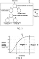
FIG. 3 , adecision model 310 is illustrated, in accordance with various embodiments.Decision model 211,decision model 212,decision model 213,decision model 214,decision model 215,decision model 216,decision model 217, and/ordecision model 218 ofFIG. 2 may be similar todecision model 310.Decision model 310 may receive a plurality of state variables.Decision model 310 may receive a plurality of first DC link capacitor state variables, such as input current (IIN) for example. In various embodiments, the plurality of first DC link capacitor state variables are an array of values as a function of time.Decision model 310 may determine, in turn, whether each of the plurality of first DC link capacitor state variables are less than athreshold value 340. Thethreshold value 340 is a predetermined value, in accordance with various embodiments. Furthermore, although described herein as determining whether each of the plurality of first DC link capacitor state variables are less than a threshold value,decision model 310 may conversely determine whether each of the plurality of first DC link capacitor state variables are greater than a threshold value without departing from the scope of the present disclosure. For each of the capacitor state variables that are less than the threshold value, thedecision model 310 determines a deviation (i.e., difference) of the capacitor state variable from thethreshold value 340. Thedecision model 310 then determines whether this deviation happened with apredetermined threshold time 342. As an example, when analyzing input current (IIN), the threshold value may be in units of amperes, such as 10 amperes for example. However, the threshold value may be any value and further may vary depending on the status of operation of the power conversion system. Continuing with the example, if the capacitor state variable is 6 amperes, thethreshold value 340 is 10 amperes, and thethreshold time 342 is 0.5 seconds, then thedecision model 310 may calculate the deviation of the state variable from the threshold value as 4 amperes (10 amperes - 6 amperes). Thedecision model 310 may then determine whether the deviation from 10 amperes occurred within 0.5 seconds. In this example, thedecision model 310 may subtract the time (t1) that the state variable was at the threshold value (i.e., 10 amperes) from the time (t2) at which the state variable reached 6 amperes to determine whether this deviation from thethreshold value 340 was within thethreshold time 342 of 0.5 seconds. In response to this deviation being calculated to have happened within thethreshold time 342, then the capacitor state variable counts towards a higher probability of failure (PI). In response to this deviation being calculated to have not happened within thethreshold time 342, then the capacitor state variable counts against a higher probability of failure (P2). After all of the plurality of first DC link capacitor state variables have been analyzed, an individual (e.g., a first) probability of failure corresponding to the first DC link capacitor state variable is determined by the following equation:
- In various embodiments, the
threshold value 340 andthreshold time 342 may be predetermined during a training phase of thedecision model 310. For example, during the training phase of the decision models, the values of respective parameters can be used to check which threshold values provide the most accurate probability of failure predictions. For example, considering a decision model for input current, during the training phase all the values of the input current and the respective time may be used to check which provides the best threshold for accurately predicting probability of failure. In various embodiments, Gini index (Gi) may be defined:
- Each value in the training dataset (i.e. input current and the corresponding time) may be associated with this Gini Index and the one with the lowest Gini index value may be used as the threshold value and threshold time. In this manner, the most optimal threshold values may be used for determining probability. However, it is contemplated herein that various other methods for determining threshold values may be used without departing from the scope of the present disclosure.
- With reference again to
FIG. 2 ,controller 100 may iterate through the logic of decision model 310 (seeFIG. 3 ) for each of the DC link capacitor state variables. After an individual probability of failure is calculated for each of the DC link capacitor state variables,controller 100 may calculate a final probability offailure 222 of the DC link capacitor. The final probability offailure 222 of the DC link capacitor may be calculated by taking an average value of the individual probabilities of failure of the DC link capacitor values. The final probability offailure 222 of the DC link capacitor may then be used to estimate the remaining lifespan, or a failure time, of the DC link capacitor usingprofile mapper 230.Profile mapper 230 may utilize a predetermined curve, such as the cumulative distribution function of capacitor failure curve represented inFIG. 4 for example, to estimate the remaining lifespan. - With reference to
FIG. 4 , acurve 400 representing the cumulative distribution function of capacitor failure versus time is provided. The cumulative distribution function (CDF) may be calculated as:


- t: time (hours)
- µ: mean of the distribution
- σ: standard deviation
- x: failure rate
- The obtained graph is depicted in
FIG. 4 . Thecurve 400 can be represented in matrix form (2D) and may be stored in memory. As illustrated, the maximum value ofcurve 400 is 1, which represents 100% probability of failure of the DC link capacitor (region II), and the minimum value ofcurve 400 is 0, which represents 0% probability of failure of the DC link capacitor. If the final probability offailure 222 of the DC link capacitor is less than 100% (e.g., ≤ 0.99) (region I), then the failure time can be predicted. The remaining lifespan of the DC link capacitor may be determined by fitting the final probability offailure 222 of the DC link capacitor tocurve 400, thereby providing an estimated remaining lifespan of the DC link capacitor. For example, if the final probability offailure 222 of the DC link capacitor is 0.5 (T1'), then the estimated remaining lifespan would be calculated as T2'-T1'. - With reference to
FIG. 5 , amethod 500 for monitoring DC link capacitor health is provided, in accordance with various embodiments.Method 500 includes receiving, by a controller, a plurality of first DC link capacitor state variables (step 510).Method 500 includes determining, by the controller, whether each of the first DC link capacitor state variables is less than a first threshold value (step 520).Method 500 includes calculating, by the controller, a deviation of each of the first DC link capacitor state variables from the first threshold value, in response to the first DC link capacitor state variable being less than the first threshold value (step 530).Method 500 includes determining, by the controller, whether each of the deviations of the first DC link capacitor state variables occurred within a first threshold time (step 540).Method 500 includes calculating, by the controller, a first probability of failure of a DC link capacitor by dividing a total number of the deviations of the first DC link capacitor state variables that occurred within the first threshold time by a total number of the plurality of first DC link capacitor values (step 550).Method 500 includes repeating steps 510-550 for a plurality of second DC link capacitor state variables (step 560).Method 500 includes calculating, by the controller, a final probability of failure of the DC link capacitor (step 570).Method 500 includes estimating, by the controller, a remaining lifespan of the DC link capacitor (step 580). - With combined reference to
FIG. 2 , step 510 may include receiving, bycontroller 100, a plurality of first DC link capacitor state variables (e.g., one ofstate variables controller 100, whether each of the first DC link capacitor state variables is less than a first threshold value (e.g.,threshold value 340 ofFIG. 3 ). Step 530 may include calculating, bycontroller 100, a deviation of each of the first DC link capacitor state variables from the first threshold value, in response to the first DC link capacitor state variable being less than the first threshold value. Step 540 may include determining, bycontroller 100, whether each of the deviations of the first DC link capacitor state variables occurred within a first threshold time (e.g.,threshold time 342 ofFIG. 3 ). Step 550 may include calculating, bycontroller 100, a first probability of failure of a DC link capacitor using equation 1 as provided herein. Step 560 may include repeatingsteps 510 through 550 using a plurality of second DC link capacitor state variables (e.g., one ofstate variables controller 100, final probability offailure 222 of DC link capacitor 106 (seeFIG. 1 ). Step 580 may include estimating, bycontroller 100, a remaining lifespan of the DC link capacitor usingprofile mapper 230 as described herein. - Benefits, other advantages, and solutions to problems have been described herein with regard to specific embodiments. Furthermore, the connecting lines shown in the various figures contained herein are intended to represent exemplary functional relationships and/or physical couplings between the various elements. It should be noted that many alternative or additional functional relationships or physical connections may be present in a practical system. However, the benefits, advantages, solutions to problems, and any elements that may cause any benefit, advantage, or solution to occur or become more pronounced are not to be construed as critical, required, or essential features or elements of the disclosure. The scope of the disclosure is accordingly to be limited by nothing other than the appended claims, in which reference to an element in the singular is not intended to mean "one and only one" unless explicitly so stated, but rather "one or more." Moreover, where a phrase similar to "at least one of A, B, or C" is used in the claims, it is intended that the phrase be interpreted to mean that A alone may be present in an embodiment, B alone may be present in an embodiment, C alone may be present in an embodiment, or that any combination of the elements A, B and C may be present in a single embodiment; for example, A and B, A and C, B and C, or A and B and C. Different cross-hatching is used throughout the figures to denote different parts but not necessarily to denote the same or different materials.
- Systems, methods and apparatus are provided herein. In the detailed description herein, references to "one embodiment", "an embodiment", "various embodiments", etc., indicate that the embodiment described may include a particular feature, structure, or characteristic, but every embodiment may not necessarily include the particular feature, structure, or characteristic. Moreover, such phrases are not necessarily referring to the same embodiment. Further, when a particular feature, structure, or characteristic is described in connection with an embodiment, it is submitted that it is within the knowledge of one skilled in the art to affect such feature, structure, or characteristic in connection with other embodiments whether or not explicitly described. After reading the description, it will be apparent to one skilled in the relevant art(s) how to implement the disclosure in alternative embodiments.
- Furthermore, no element, component, or method step in the present disclosure is intended to be dedicated to the public regardless of whether the element, component, or method step is explicitly recited in the claims. As used herein, the terms "comprises", "comprising", or any other variation thereof, are intended to cover a non-exclusive inclusion, such that a process, method, article, or apparatus that comprises a list of elements does not include only those elements but may include other elements not expressly listed or inherent to such process, method, article, or apparatus.
Claims (15)
- A method for monitoring DC link capacitor health, comprising:receiving, by a controller, a plurality of first DC link capacitor state variables;determining, by the controller, whether each of the first DC link capacitor state variables is less than a first threshold value;calculating, by the controller, a deviation of each of the first DC link capacitor state variables from the first threshold value, in response to the first DC link capacitor state variable being less than the first threshold value;determining, by the controller, whether each of the deviations of the first DC link capacitor state variables occurred within a first threshold time; andcalculating, by the controller, a first probability of failure of the DC link capacitor by dividing a total number of the deviations of the first DC link capacitor state variables that occurred within the first threshold time by a total number of the plurality of first DC link capacitor values.
- The method of claim 1, further comprising:receiving, by the controller, a plurality of second DC link capacitor state variables;determining, by the controller, whether each of the second DC link capacitor state variables is less than a second threshold value;calculating, by the controller, a deviation of each of the second DC link capacitor state variables from the second threshold value, in response to the second DC link capacitor state variable being less than the second threshold value;determining, by the controller, whether each of the deviations of the second DC link capacitor state variables occurred within a second threshold time; andcalculating, by the controller, a second probability of failure of a DC link capacitor by dividing a total number of the deviations of the second DC link capacitor state variables that occurred within the second threshold time by a total number of the plurality of second DC link capacitor values.
- The method of claim 2, further comprising calculating, by the controller, a final probability of failure by calculating a mean value of the first probability of failure and the second probability of failure, and preferably further comprising estimating, by the controller, a remaining lifespan of the DC link capacitor.
- The method of any preceding claim, wherein the plurality of first DC link capacitor state variables includes at least one of an input current, an input voltage, a DC link voltage, an output current, an output voltage, a DC link capacitor current, a DC link capacitor temperature, and a loading power.
- The method of claim 2, wherein the plurality of second DC link capacitor state variables includes at least one of an input current, an input voltage, a DC link voltage, an output current, an output voltage, a DC link capacitor current, a DC link capacitor temperature, and a loading power.
- The method of any preceding claim, wherein the first threshold value is a predetermined value.
- The method of any preceding claim, wherein the first threshold time is a predetermined value.
- The method of any preceding claim, wherein the total number of the plurality of first DC link capacitor values is equal to a sum of the total number of the deviations of the first DC link capacitor state variables that occurred within the first threshold time and a total number of the deviations of the first DC link capacitor state variables that occurred outside of the first threshold time.
- A system for monitoring DC link capacitor health for use with a power conversion system, comprising:a controller (100); anda tangible, non-transitory memory configured to communicate with the controller, the tangible, non-transitory memory having instructions stored thereon that, in response to execution by the processor, cause the controller to perform operations comprising:receiving, by the controller, a plurality of first DC link capacitor state variables;determining, by the controller, whether each of the first DC link capacitor state variables is less than a first threshold value;calculating, by the controller, a deviation of each of the first DC link capacitor state variables from the first threshold value, in response to the first DC link capacitor state variable being less than the first threshold value;determining, by the controller, whether each of the deviations of the first DC link capacitor state variables occurred within a first threshold time; andcalculating, by the controller, a first probability of failure of the DC link capacitor by dividing a total number of the deviations of the first DC link capacitor state variables that occurred within the first threshold time by a total number of the plurality of first DC link capacitor values.
- The system of claim 9, wherein the instructions cause the controller to perform further operations comprising:receiving, by the controller, a plurality of second DC link capacitor state variables;determining, by the controller, whether each of the second DC link capacitor state variables is less than a second threshold value;calculating, by the controller, a deviation of each of the second DC link capacitor state variables from the second threshold value, in response to the second DC link capacitor state variable being less than the second threshold value;determining, by the controller, whether each of the deviations of the second DC link capacitor state variables occurred within a second threshold time; andcalculating, by the controller, a second probability of failure of the DC link capacitor by dividing a total number of the deviations of the second DC link capacitor state variables that occurred within the second threshold time by a total number of the plurality of second DC link capacitor values.
- The system of claim 10, wherein the instructions cause the controller to perform further operations comprising calculating, by the controller, a final probability of failure by calculating a mean value of the first probability and the second probability, and preferably wherein the instructions cause the controller to perform further operations comprising estimating, by the controller, a remaining lifespan of the DC link capacitor.
- The system of any of claims 9-11, wherein the plurality of first DC link capacitor state variables includes at least one of an input current, an input voltage, a DC link voltage, an output current, an output voltage, a DC link capacitor current, a DC link capacitor temperature, and a loading power, and preferably, when dependent on claim 10, wherein the plurality of second DC link capacitor state variables includes at least one of an input current, an input voltage, a DC link voltage, an output current, an output voltage, a DC link capacitor current, a DC link capacitor temperature, and a loading power.
- The system of any of claims 9-12, wherein the first threshold value is a predetermined value; and/or
wherein the first threshold time is a predetermined value; and/or
wherein the total number of the plurality of first DC link capacitor values is equal to a sum of the total number of the deviations of the first DC link capacitor state variables that occurred within the first threshold time and a total number of the deviations of the first DC link capacitor state variables that occurred outside of the first threshold time. - A power conversion system, comprising:a DC link capacitor (106);a controller (100) configured to monitor a plurality of DC link capacitor state variables; anda tangible, non-transitory memory configured to communicate with the controller, the tangible, non-transitory memory having instructions stored thereon that, in response to execution by the processor, cause the controller to perform operations comprising:receiving, by the controller, a plurality of first DC link capacitor state variables;determining, by the controller, whether each of the first DC link capacitor state variables is less than a first threshold value;calculating, by the controller, a deviation of each of the first DC link capacitor state variables from the first threshold value, in response to the first DC link capacitor state variable being less than the first threshold value;determining, by the controller, whether each of the deviations of the first DC link capacitor state variables occurred within a first threshold time; andcalculating, by the controller, a first probability of failure of a DC link capacitor by dividing a total number of the deviations of the first DC link capacitor state variables that occurred within the first threshold time by a total number of the plurality of first DC link capacitor values.
- The power conversion system of claim 14, wherein the instructions cause the controller to perform further operations comprising:receiving, by the controller, a plurality of second DC link capacitor state variables;determining, by the controller, whether each of the second DC link capacitor state variables is less than a second threshold value;calculating, by the controller, a deviation of each of the second DC link capacitor state variables from the second threshold value, in response to the second DC link capacitor state variable being less than the second threshold value;determining, by the controller, whether each of the deviations of the second DC link capacitor state variables occurred within a second threshold time; andcalculating, by the controller, a second probability of failure of a DC link capacitor by dividing a total number of the deviations of the second DC link capacitor state variables that occurred within the second threshold time by a total number of the plurality of second DC link capacitor values.
Applications Claiming Priority (1)
| Application Number | Priority Date | Filing Date | Title |
|---|---|---|---|
| IN202041003631 | 2020-01-27 |
Publications (2)
| Publication Number | Publication Date |
|---|---|
| EP3855613A1 true EP3855613A1 (en) | 2021-07-28 |
| EP3855613B1 EP3855613B1 (en) | 2024-10-23 |
Family
ID=74215745
Family Applications (1)
| Application Number | Title | Priority Date | Filing Date |
|---|---|---|---|
| EP21153045.6A Active EP3855613B1 (en) | 2020-01-27 | 2021-01-22 | On-board capacitor health monitoring systems and methods |
Country Status (2)
| Country | Link |
|---|---|
| US (1) | US11619675B2 (en) |
| EP (1) | EP3855613B1 (en) |
Families Citing this family (4)
| Publication number | Priority date | Publication date | Assignee | Title |
|---|---|---|---|---|
| CN113702780B (en) * | 2021-08-20 | 2024-01-19 | 中国南方电网有限责任公司超高压输电公司大理局 | High-voltage capacitor online monitoring method and device based on BP neural network |
| JP7709879B2 (en) * | 2021-09-17 | 2025-07-17 | ナブテスコ株式会社 | Automatic door device, method, program and door management system |
| CN115420971B (en) * | 2022-08-10 | 2026-05-01 | 中国电子产品可靠性与环境试验研究所((工业和信息化部电子第五研究所)(中国赛宝实验室)) | Fault prediction methods, devices and power conversion systems for power conversion equipment |
| CN118604557A (en) * | 2024-05-13 | 2024-09-06 | 国网福建省电力有限公司 | A capacitor fault diagnosis method and terminal |
Citations (1)
| Publication number | Priority date | Publication date | Assignee | Title |
|---|---|---|---|---|
| US20160315575A1 (en) * | 2015-04-27 | 2016-10-27 | Fanuc Corporation | Motor control device having life prediction unit of smoothing capacitor |
Family Cites Families (5)
| Publication number | Priority date | Publication date | Assignee | Title |
|---|---|---|---|---|
| US7081761B2 (en) * | 2004-07-14 | 2006-07-25 | General Motors Corporation | Ultracapacitor useful life prediction |
| US8796982B2 (en) * | 2011-12-15 | 2014-08-05 | Eaton Corporation | System and method for detecting phase loss and diagnosing DC link capacitor health in an adjustable speed drive |
| US20170336463A1 (en) | 2016-05-23 | 2017-11-23 | Exxelia Technologies | Method for determining the maximum time when a capacitor should be replaced |
| EP3477314B1 (en) | 2017-10-24 | 2020-09-30 | Mitsubishi Electric R & D Centre Europe B.V. | A method for on-line monitoring a dc-bus capacitor |
| KR102687178B1 (en) * | 2019-04-01 | 2024-07-22 | 현대자동차주식회사 | Multi-input charging system and method using motor driving system |
-
2020
- 2020-12-31 US US17/139,140 patent/US11619675B2/en active Active
-
2021
- 2021-01-22 EP EP21153045.6A patent/EP3855613B1/en active Active
Patent Citations (1)
| Publication number | Priority date | Publication date | Assignee | Title |
|---|---|---|---|---|
| US20160315575A1 (en) * | 2015-04-27 | 2016-10-27 | Fanuc Corporation | Motor control device having life prediction unit of smoothing capacitor |
Also Published As
| Publication number | Publication date |
|---|---|
| US20210231744A1 (en) | 2021-07-29 |
| US11619675B2 (en) | 2023-04-04 |
| EP3855613B1 (en) | 2024-10-23 |
Similar Documents
| Publication | Publication Date | Title |
|---|---|---|
| EP3855613B1 (en) | On-board capacitor health monitoring systems and methods | |
| EP3992648B1 (en) | Apparatus and method for diagnosing battery | |
| US7929323B2 (en) | Method and apparatus for pre-charging power converters and diagnosing pre-charge faults | |
| KR101298661B1 (en) | Voltage monitoring apparatus | |
| US9397593B2 (en) | Motor control device | |
| US20100161259A1 (en) | Aging status diagnostic apparatus for power conversion system, and method their of | |
| US20250130286A1 (en) | Battery system state of health monitoring system | |
| Kamel et al. | Capacitor aging detection for the DC filters in the power electronic converters using ANFIS algorithm | |
| US9880228B2 (en) | Method and system for measuring the integrity of a power converter | |
| US11340310B2 (en) | Voltage imbalance assessment method and power conversion device | |
| KR20190014074A (en) | Diagnostic equipment of motors | |
| CN111259316A (en) | Method for calculating residual life of capacitor | |
| CN111725992B (en) | Multiphase converter | |
| Nathan et al. | Review of condition monitoring methods for capacitors used in power converters | |
| EP2940850A1 (en) | A method for monitoring DC link capacitance in power converters | |
| JP2019193383A (en) | Power converter and abnormality detection method | |
| KR101548327B1 (en) | Battery diagnosis apparatus | |
| Al-Sheikh et al. | A sensor fault diagnosis scheme for a DC/DC converter used in hybrid electric vehicles | |
| CN118980983A (en) | A sensor detection method and a charger system | |
| US12181535B2 (en) | Method and device for estimating the usable charge capacity of an electrical energy store | |
| CN112798869B (en) | Capacitance detection method and system for unit series type converter | |
| KR100579923B1 (en) | How to determine the failure of DC link capacitors in electric vehicles | |
| CN120900120B (en) | Remote fault diagnosis method and system for medium-frequency electrotherapy instrument | |
| EP3671229B1 (en) | Device and method for self adjusting an electrical threshold for detecting a power failure | |
| US12498408B2 (en) | Determining parameters of a filter circuit |
Legal Events
| Date | Code | Title | Description |
|---|---|---|---|
| PUAI | Public reference made under article 153(3) epc to a published international application that has entered the european phase |
Free format text: ORIGINAL CODE: 0009012 |
|
| STAA | Information on the status of an ep patent application or granted ep patent |
Free format text: STATUS: THE APPLICATION HAS BEEN PUBLISHED |
|
| AK | Designated contracting states |
Kind code of ref document: A1 Designated state(s): AL AT BE BG CH CY CZ DE DK EE ES FI FR GB GR HR HU IE IS IT LI LT LU LV MC MK MT NL NO PL PT RO RS SE SI SK SM TR |
|
| STAA | Information on the status of an ep patent application or granted ep patent |
Free format text: STATUS: REQUEST FOR EXAMINATION WAS MADE |
|
| 17P | Request for examination filed |
Effective date: 20220128 |
|
| RBV | Designated contracting states (corrected) |
Designated state(s): AL AT BE BG CH CY CZ DE DK EE ES FI FR GB GR HR HU IE IS IT LI LT LU LV MC MK MT NL NO PL PT RO RS SE SI SK SM TR |
|
| P01 | Opt-out of the competence of the unified patent court (upc) registered |
Effective date: 20230922 |
|
| GRAP | Despatch of communication of intention to grant a patent |
Free format text: ORIGINAL CODE: EPIDOSNIGR1 |
|
| STAA | Information on the status of an ep patent application or granted ep patent |
Free format text: STATUS: GRANT OF PATENT IS INTENDED |
|
| RIC1 | Information provided on ipc code assigned before grant |
Ipc: H02M 1/32 20070101ALI20240501BHEP Ipc: H02M 7/537 20060101ALI20240501BHEP Ipc: H02M 7/06 20060101ALI20240501BHEP Ipc: H02M 5/458 20060101AFI20240501BHEP |
|
| INTG | Intention to grant announced |
Effective date: 20240605 |
|
| GRAS | Grant fee paid |
Free format text: ORIGINAL CODE: EPIDOSNIGR3 |
|
| GRAA | (expected) grant |
Free format text: ORIGINAL CODE: 0009210 |
|
| STAA | Information on the status of an ep patent application or granted ep patent |
Free format text: STATUS: THE PATENT HAS BEEN GRANTED |
|
| AK | Designated contracting states |
Kind code of ref document: B1 Designated state(s): AL AT BE BG CH CY CZ DE DK EE ES FI FR GB GR HR HU IE IS IT LI LT LU LV MC MK MT NL NO PL PT RO RS SE SI SK SM TR |
|
| REG | Reference to a national code |
Ref country code: GB Ref legal event code: FG4D |
|
| REG | Reference to a national code |
Ref country code: CH Ref legal event code: EP |
|
| REG | Reference to a national code |
Ref country code: DE Ref legal event code: R096 Ref document number: 602021020514 Country of ref document: DE |
|
| REG | Reference to a national code |
Ref country code: IE Ref legal event code: FG4D |
|
| REG | Reference to a national code |
Ref country code: LT Ref legal event code: MG9D |
|
| REG | Reference to a national code |
Ref country code: NL Ref legal event code: MP Effective date: 20241023 |
|
| REG | Reference to a national code |
Ref country code: AT Ref legal event code: MK05 Ref document number: 1735670 Country of ref document: AT Kind code of ref document: T Effective date: 20241023 |
|
| PG25 | Lapsed in a contracting state [announced via postgrant information from national office to epo] |
Ref country code: NL Free format text: LAPSE BECAUSE OF FAILURE TO SUBMIT A TRANSLATION OF THE DESCRIPTION OR TO PAY THE FEE WITHIN THE PRESCRIBED TIME-LIMIT Effective date: 20241023 |
|
| PG25 | Lapsed in a contracting state [announced via postgrant information from national office to epo] |
Ref country code: NL Free format text: LAPSE BECAUSE OF FAILURE TO SUBMIT A TRANSLATION OF THE DESCRIPTION OR TO PAY THE FEE WITHIN THE PRESCRIBED TIME-LIMIT Effective date: 20241023 |
|
| PG25 | Lapsed in a contracting state [announced via postgrant information from national office to epo] |
Ref country code: IS Free format text: LAPSE BECAUSE OF FAILURE TO SUBMIT A TRANSLATION OF THE DESCRIPTION OR TO PAY THE FEE WITHIN THE PRESCRIBED TIME-LIMIT Effective date: 20250223 Ref country code: HR Free format text: LAPSE BECAUSE OF FAILURE TO SUBMIT A TRANSLATION OF THE DESCRIPTION OR TO PAY THE FEE WITHIN THE PRESCRIBED TIME-LIMIT Effective date: 20241023 Ref country code: PT Free format text: LAPSE BECAUSE OF FAILURE TO SUBMIT A TRANSLATION OF THE DESCRIPTION OR TO PAY THE FEE WITHIN THE PRESCRIBED TIME-LIMIT Effective date: 20250224 |
|
| PG25 | Lapsed in a contracting state [announced via postgrant information from national office to epo] |
Ref country code: FI Free format text: LAPSE BECAUSE OF FAILURE TO SUBMIT A TRANSLATION OF THE DESCRIPTION OR TO PAY THE FEE WITHIN THE PRESCRIBED TIME-LIMIT Effective date: 20241023 |
|
| PG25 | Lapsed in a contracting state [announced via postgrant information from national office to epo] |
Ref country code: BG Free format text: LAPSE BECAUSE OF FAILURE TO SUBMIT A TRANSLATION OF THE DESCRIPTION OR TO PAY THE FEE WITHIN THE PRESCRIBED TIME-LIMIT Effective date: 20241023 |
|
| PG25 | Lapsed in a contracting state [announced via postgrant information from national office to epo] |
Ref country code: ES Free format text: LAPSE BECAUSE OF FAILURE TO SUBMIT A TRANSLATION OF THE DESCRIPTION OR TO PAY THE FEE WITHIN THE PRESCRIBED TIME-LIMIT Effective date: 20241023 |
|
| PG25 | Lapsed in a contracting state [announced via postgrant information from national office to epo] |
Ref country code: NO Free format text: LAPSE BECAUSE OF FAILURE TO SUBMIT A TRANSLATION OF THE DESCRIPTION OR TO PAY THE FEE WITHIN THE PRESCRIBED TIME-LIMIT Effective date: 20250123 |
|
| PG25 | Lapsed in a contracting state [announced via postgrant information from national office to epo] |
Ref country code: AT Free format text: LAPSE BECAUSE OF FAILURE TO SUBMIT A TRANSLATION OF THE DESCRIPTION OR TO PAY THE FEE WITHIN THE PRESCRIBED TIME-LIMIT Effective date: 20241023 Ref country code: LV Free format text: LAPSE BECAUSE OF FAILURE TO SUBMIT A TRANSLATION OF THE DESCRIPTION OR TO PAY THE FEE WITHIN THE PRESCRIBED TIME-LIMIT Effective date: 20241023 Ref country code: GR Free format text: LAPSE BECAUSE OF FAILURE TO SUBMIT A TRANSLATION OF THE DESCRIPTION OR TO PAY THE FEE WITHIN THE PRESCRIBED TIME-LIMIT Effective date: 20250124 |
|
| PG25 | Lapsed in a contracting state [announced via postgrant information from national office to epo] |
Ref country code: PL Free format text: LAPSE BECAUSE OF FAILURE TO SUBMIT A TRANSLATION OF THE DESCRIPTION OR TO PAY THE FEE WITHIN THE PRESCRIBED TIME-LIMIT Effective date: 20241023 |
|
| PG25 | Lapsed in a contracting state [announced via postgrant information from national office to epo] |
Ref country code: RS Free format text: LAPSE BECAUSE OF FAILURE TO SUBMIT A TRANSLATION OF THE DESCRIPTION OR TO PAY THE FEE WITHIN THE PRESCRIBED TIME-LIMIT Effective date: 20250123 |
|
| PG25 | Lapsed in a contracting state [announced via postgrant information from national office to epo] |
Ref country code: SM Free format text: LAPSE BECAUSE OF FAILURE TO SUBMIT A TRANSLATION OF THE DESCRIPTION OR TO PAY THE FEE WITHIN THE PRESCRIBED TIME-LIMIT Effective date: 20241023 |
|
| PG25 | Lapsed in a contracting state [announced via postgrant information from national office to epo] |
Ref country code: DK Free format text: LAPSE BECAUSE OF FAILURE TO SUBMIT A TRANSLATION OF THE DESCRIPTION OR TO PAY THE FEE WITHIN THE PRESCRIBED TIME-LIMIT Effective date: 20241023 |
|
| PG25 | Lapsed in a contracting state [announced via postgrant information from national office to epo] |
Ref country code: EE Free format text: LAPSE BECAUSE OF FAILURE TO SUBMIT A TRANSLATION OF THE DESCRIPTION OR TO PAY THE FEE WITHIN THE PRESCRIBED TIME-LIMIT Effective date: 20241023 |
|
| PG25 | Lapsed in a contracting state [announced via postgrant information from national office to epo] |
Ref country code: RO Free format text: LAPSE BECAUSE OF FAILURE TO SUBMIT A TRANSLATION OF THE DESCRIPTION OR TO PAY THE FEE WITHIN THE PRESCRIBED TIME-LIMIT Effective date: 20241023 |
|
| REG | Reference to a national code |
Ref country code: DE Ref legal event code: R097 Ref document number: 602021020514 Country of ref document: DE |
|
| PG25 | Lapsed in a contracting state [announced via postgrant information from national office to epo] |
Ref country code: SK Free format text: LAPSE BECAUSE OF FAILURE TO SUBMIT A TRANSLATION OF THE DESCRIPTION OR TO PAY THE FEE WITHIN THE PRESCRIBED TIME-LIMIT Effective date: 20241023 |
|
| PG25 | Lapsed in a contracting state [announced via postgrant information from national office to epo] |
Ref country code: CZ Free format text: LAPSE BECAUSE OF FAILURE TO SUBMIT A TRANSLATION OF THE DESCRIPTION OR TO PAY THE FEE WITHIN THE PRESCRIBED TIME-LIMIT Effective date: 20241023 |
|
| PG25 | Lapsed in a contracting state [announced via postgrant information from national office to epo] |
Ref country code: IT Free format text: LAPSE BECAUSE OF FAILURE TO SUBMIT A TRANSLATION OF THE DESCRIPTION OR TO PAY THE FEE WITHIN THE PRESCRIBED TIME-LIMIT Effective date: 20241023 |
|
| PLBE | No opposition filed within time limit |
Free format text: ORIGINAL CODE: 0009261 |
|
| REG | Reference to a national code |
Ref country code: CH Ref legal event code: PL |
|
| STAA | Information on the status of an ep patent application or granted ep patent |
Free format text: STATUS: NO OPPOSITION FILED WITHIN TIME LIMIT |
|
| PG25 | Lapsed in a contracting state [announced via postgrant information from national office to epo] |
Ref country code: SE Free format text: LAPSE BECAUSE OF FAILURE TO SUBMIT A TRANSLATION OF THE DESCRIPTION OR TO PAY THE FEE WITHIN THE PRESCRIBED TIME-LIMIT Effective date: 20241023 |
|
| PG25 | Lapsed in a contracting state [announced via postgrant information from national office to epo] |
Ref country code: MC Free format text: LAPSE BECAUSE OF FAILURE TO SUBMIT A TRANSLATION OF THE DESCRIPTION OR TO PAY THE FEE WITHIN THE PRESCRIBED TIME-LIMIT Effective date: 20241023 Ref country code: LU Free format text: LAPSE BECAUSE OF NON-PAYMENT OF DUE FEES Effective date: 20250122 |
|
| 26N | No opposition filed |
Effective date: 20250724 |
|
| PG25 | Lapsed in a contracting state [announced via postgrant information from national office to epo] |
Ref country code: BE Free format text: LAPSE BECAUSE OF NON-PAYMENT OF DUE FEES Effective date: 20250131 |
|
| PG25 | Lapsed in a contracting state [announced via postgrant information from national office to epo] |
Ref country code: CH Free format text: LAPSE BECAUSE OF NON-PAYMENT OF DUE FEES Effective date: 20250131 |
|
| REG | Reference to a national code |
Ref country code: BE Ref legal event code: MM Effective date: 20250131 |
|
| PGFP | Annual fee paid to national office [announced via postgrant information from national office to epo] |
Ref country code: GB Payment date: 20251217 Year of fee payment: 6 |
|
| PGFP | Annual fee paid to national office [announced via postgrant information from national office to epo] |
Ref country code: FR Payment date: 20251217 Year of fee payment: 6 |
|
| PG25 | Lapsed in a contracting state [announced via postgrant information from national office to epo] |
Ref country code: IE Free format text: LAPSE BECAUSE OF NON-PAYMENT OF DUE FEES Effective date: 20250122 |
|
| PGFP | Annual fee paid to national office [announced via postgrant information from national office to epo] |
Ref country code: DE Payment date: 20251217 Year of fee payment: 6 |