EP3855604A1 - Generator rotor flat wire winding - Google Patents
Generator rotor flat wire winding Download PDFInfo
- Publication number
- EP3855604A1 EP3855604A1 EP21152972.2A EP21152972A EP3855604A1 EP 3855604 A1 EP3855604 A1 EP 3855604A1 EP 21152972 A EP21152972 A EP 21152972A EP 3855604 A1 EP3855604 A1 EP 3855604A1
- Authority
- EP
- European Patent Office
- Prior art keywords
- generator
- termination plate
- wire
- termination
- plate
- Prior art date
- Legal status (The legal status is an assumption and is not a legal conclusion. Google has not performed a legal analysis and makes no representation as to the accuracy of the status listed.)
- Pending
Links
Images

Classifications
-
- H—ELECTRICITY
- H02—GENERATION; CONVERSION OR DISTRIBUTION OF ELECTRIC POWER
- H02K—DYNAMO-ELECTRIC MACHINES
- H02K3/00—Details of windings
- H02K3/46—Fastening of windings on the stator or rotor structure
- H02K3/50—Fastening of winding heads, equalising connectors, or connections thereto
- H02K3/51—Fastening of winding heads, equalising connectors, or connections thereto applicable to rotors only
-
- H—ELECTRICITY
- H02—GENERATION; CONVERSION OR DISTRIBUTION OF ELECTRIC POWER
- H02K—DYNAMO-ELECTRIC MACHINES
- H02K3/00—Details of windings
- H02K3/46—Fastening of windings on the stator or rotor structure
- H02K3/52—Fastening salient pole windings or connections thereto
- H02K3/527—Fastening salient pole windings or connections thereto applicable to rotors only
-
- H—ELECTRICITY
- H02—GENERATION; CONVERSION OR DISTRIBUTION OF ELECTRIC POWER
- H02K—DYNAMO-ELECTRIC MACHINES
- H02K17/00—Asynchronous induction motors; Asynchronous induction generators
- H02K17/42—Asynchronous induction generators
-
- H—ELECTRICITY
- H02—GENERATION; CONVERSION OR DISTRIBUTION OF ELECTRIC POWER
- H02K—DYNAMO-ELECTRIC MACHINES
- H02K7/00—Arrangements for handling mechanical energy structurally associated with dynamo-electric machines, e.g. structural association with mechanical driving motors or auxiliary dynamo-electric machines
- H02K7/04—Balancing means
-
- H—ELECTRICITY
- H02—GENERATION; CONVERSION OR DISTRIBUTION OF ELECTRIC POWER
- H02K—DYNAMO-ELECTRIC MACHINES
- H02K1/00—Details of the magnetic circuit
- H02K1/06—Details of the magnetic circuit characterised by the shape, form or construction
- H02K1/22—Rotating parts of the magnetic circuit
- H02K1/24—Rotor cores with salient poles ; Variable reluctance rotors
-
- H—ELECTRICITY
- H02—GENERATION; CONVERSION OR DISTRIBUTION OF ELECTRIC POWER
- H02K—DYNAMO-ELECTRIC MACHINES
- H02K2203/00—Specific aspects not provided for in the other groups of this subclass relating to the windings
- H02K2203/03—Machines characterised by the wiring boards, i.e. printed circuit boards or similar structures for connecting the winding terminations
Definitions
- the present disclosure relates to generator wiring, and more particularly to a means of connecting flat wire windings in a generator rotor assembly.
- Flat wires have power density advantages over round wires.
- having flat wires requires installation and securing of the wires using differing terminations from the typical terminations, as with round wires.
- a generator including a stator winding, a rotor positioned radially inside the stator winding, including multiple coil assemblies each using a flat wire, a primary termination plate residing radially inside the rotor configured to connect a wire of a coil assembly to an adjacent wound coil, and a secondary termination plate residing radially inside the rotor configured to connect a wound coil to an adjacent wound coil and connect the wound coil to a terminus connection.
- the generator can include a second primary termination plate and a second secondary termination plate. Each of the termination plates can affix wires from three adjacent coils.
- the primary termination plate and the secondary termination plate can have an equal weight.
- the termination plates can include three radially directed channels configured for receiving wires of coils and affixing them in place.
- the secondary termination plate can include a curved channel configured for accepting a single wire of a single coil and affixing it to a round wire then attaching the round wire with a fastener.
- the secondary termination plate can include a fastener configured to secure a wire to the termination plate.
- the generator can further include a second secondary termination plate.
- the second secondary termination plate and the secondary termination plate can be positioned opposite each other, and the primary termination plate and the secondary termination plate are adjacent to each other.
- Each of the termination plates can be machined from a non-conductive material.
- the secondary termination plate can include a round wire coupled to a fastener.
- a series of clips can couple the flat wires of each coil assembly to the flat wires of an adjacent coil assembly and the round wire can be coupled to the flat wire by a securing the wire together at two locations.
- the termination plates are not coupled to each other.
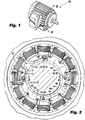
- a partial view of an exemplary embodiment of a rotor assembly in accordance with the invention is shown in Fig. 1 and is designated generally by reference character 100.
- Other embodiments of the rotor assembly in accordance with the invention, or aspects thereof, are provided in Fig. 2 as will be described.
- the methods and systems of the invention can be used to improve on symmetry and balance of the rotor during use.
- Fig. 1 shows a generator 100 with inner parts including a stator winding 102, and a rotor 104 positioned radially inside the stator winding 10 shown in in Fig. 2 .
- the rotor 104 includes multiple coil assemblies 106.
- Each coil assembly includes a flat wire 108.
- Flat wires have a power density advantages over round wires and are subject to less movement during rotation.
- Fig. 2 shows a primary termination plate 112a residing radially inside the rotor 104 configured to connect the wire of a coil assembly 106 to an adjacent wound coil 106, and a secondary termination plate 110a residing radially inside the rotor 104 which also connect a wound coil wire to an adjacent wound coil 106.
- the generator further includes a second primary termination plate 112b and a second secondary termination plate 110b.
- Each of the termination plates affix wires from four adjacent coils.
- the primary termination plates 112a/b are identical and secondary termination plates 10a/b have equal weights but have different cuts and channels 115. Therefore the secondary termination plates can be made from the same molding of a non-conductive material and be machined differently to make either plate.
- Fig. 2 further shows fasteners 117 and 118.
- Fasteners 117 and 118 secure the flat wire to the round wire on plate 110a and provide balance to the rotor when used with counterweight 128 on plate 110b.
- the termination plates 112a/b and 110a/b are not coupled to each other. This allows for easier repair while also accommodating centrifugal forces, thermal expansion and movement due to starting and stopping. Allowing for slight movement is imperative to avoid putting stress on the flat wires and other components.
- the symmetrical configuration helps with balancing.
- Each of the termination plates 112/ 110 can be machined from a non-conductive material.
- the generator 100 can further include a second secondary type of termination plate 110b.
- the second secondary termination plate 110b and the first secondary termination plate 110a are positioned opposite each other to ensure balance of rotating weights.
- Fig. 2 further shows each of the termination plates 112/110 including three radially directed channels 114 receiving flat wires 108 of coils 106 and coupling the flat wires together with clips 122 and supporting the connected wires 122 into the slots in the termination plate 110/112.
- the secondary termination 110 plate includes a curved channel 115 which accepts flat wire 108 which is attached to round wire 120 which is affixed it with a fastener 118 to round wire 120.
- a series of clips 122 are used to secure the flat wires 108 of each coil assembly 106 to the flat wires of the adjacent coil assembly 106.
- the round wire 120 is secured between the bus bar 126 and a conductive washer 124.
- the bus bar 126 is connected to a source of excitation current (not shown) from within the rotor 104.
- Fig. 4 shows counterweight 128 installed on the second secondary termination plate 110b.
- the counterweight is equivalent in mass to the conductive washer 124, bus bar 126, and round wire 120, in order to aid in creating symmetrical rotational loads during rotations of the rotor.
Landscapes
- Engineering & Computer Science (AREA)
- Power Engineering (AREA)
- Windings For Motors And Generators (AREA)
- Insulation, Fastening Of Motor, Generator Windings (AREA)
Abstract
Description
- The present disclosure relates to generator wiring, and more particularly to a means of connecting flat wire windings in a generator rotor assembly.
- A variety of options are used when wiring generators. Flat wires have power density advantages over round wires. However, having flat wires requires installation and securing of the wires using differing terminations from the typical terminations, as with round wires.
- The conventional methods and systems have generally been considered satisfactory for their intended purpose. However, there is still a need in the art for generator assemblies with flat wires having improved balancing, symmetry, and reliability. There also remains a need in the art for such assemblies and components that are economically viable. The present disclosure may provide a solution for at least one of these remaining challenges.
- A generator is provided including a stator winding, a rotor positioned radially inside the stator winding, including multiple coil assemblies each using a flat wire, a primary termination plate residing radially inside the rotor configured to connect a wire of a coil assembly to an adjacent wound coil, and a secondary termination plate residing radially inside the rotor configured to connect a wound coil to an adjacent wound coil and connect the wound coil to a terminus connection. The generator can include a second primary termination plate and a second secondary termination plate. Each of the termination plates can affix wires from three adjacent coils. The primary termination plate and the secondary termination plate can have an equal weight.
- The termination plates can include three radially directed channels configured for receiving wires of coils and affixing them in place. The secondary termination plate can include a curved channel configured for accepting a single wire of a single coil and affixing it to a round wire then attaching the round wire with a fastener. The secondary termination plate can include a fastener configured to secure a wire to the termination plate.
- The generator can further include a second secondary termination plate. The second secondary termination plate and the secondary termination plate can be positioned opposite each other, and the primary termination plate and the secondary termination plate are adjacent to each other. Each of the termination plates can be machined from a non-conductive material. The secondary termination plate can include a round wire coupled to a fastener.
- A series of clips can couple the flat wires of each coil assembly to the flat wires of an adjacent coil assembly and the round wire can be coupled to the flat wire by a securing the wire together at two locations. The termination plates are not coupled to each other.
- These and other features of the systems and methods of the subject disclosure will become more readily apparent to those skilled in the art from the following detailed description of the preferred embodiments taken in conjunction with the drawings.
- So that those skilled in the art to which the subject invention appertains will readily understand how to make and use the devices and methods of the subject invention without undue experimentation, preferred embodiments thereof will be described in detail herein below with reference to certain figures, wherein:
-
Fig. 1 is an isometric view of a generator with a flat wire rotor winding; -
Fig. 2 is a front view of the rotor face; -
Fig. 3 is a side view of a fastener of a rotor face; and -
Fig. 4 is a side view of a fastener of the rotor face plate intended to balance the weight. - Reference will now be made to the drawings wherein like reference numerals identify similar structural features or aspects of the subject invention. For purposes of explanation and illustration, and not limitation, a partial view of an exemplary embodiment of a rotor assembly in accordance with the invention is shown in
Fig. 1 and is designated generally byreference character 100. Other embodiments of the rotor assembly in accordance with the invention, or aspects thereof, are provided inFig. 2 as will be described. The methods and systems of the invention can be used to improve on symmetry and balance of the rotor during use. -
Fig. 1 shows agenerator 100 with inner parts including a stator winding 102, and arotor 104 positioned radially inside the stator winding 10 shown in inFig. 2 . Therotor 104 includesmultiple coil assemblies 106. Each coil assembly includes aflat wire 108. Flat wires have a power density advantages over round wires and are subject to less movement during rotation. -
Fig. 2 shows aprimary termination plate 112a residing radially inside therotor 104 configured to connect the wire of acoil assembly 106 to anadjacent wound coil 106, and a secondary termination plate 110a residing radially inside therotor 104 which also connect a wound coil wire to anadjacent wound coil 106. The generator further includes a secondprimary termination plate 112b and a second secondary termination plate 110b. Each of the termination plates affix wires from four adjacent coils. Theprimary termination plates 112a/b are identical and secondary termination plates 10a/b have equal weights but have different cuts andchannels 115. Therefore the secondary termination plates can be made from the same molding of a non-conductive material and be machined differently to make either plate. -
Fig. 2 further showsfasteners Fasteners counterweight 128 on plate 110b. These are detailed inFigures 3 and 4 . Thetermination plates 112a/b and 110a/b are not coupled to each other. This allows for easier repair while also accommodating centrifugal forces, thermal expansion and movement due to starting and stopping. Allowing for slight movement is imperative to avoid putting stress on the flat wires and other components. The symmetrical configuration helps with balancing. Each of the termination plates 112/ 110 can be machined from a non-conductive material. Thegenerator 100 can further include a second secondary type of termination plate 110b. The second secondary termination plate 110b and the first secondary termination plate 110a are positioned opposite each other to ensure balance of rotating weights. -
Fig. 2 further shows each of the termination plates 112/110 including three radially directedchannels 114 receivingflat wires 108 ofcoils 106 and coupling the flat wires together withclips 122 and supporting the connectedwires 122 into the slots in the termination plate 110/112. The secondary termination 110 plate includes acurved channel 115 which acceptsflat wire 108 which is attached toround wire 120 which is affixed it with afastener 118 toround wire 120. - A series of
clips 122 are used to secure theflat wires 108 of eachcoil assembly 106 to the flat wires of theadjacent coil assembly 106. With reference toFigure 3 , theround wire 120 is secured between thebus bar 126 and aconductive washer 124. Thebus bar 126 is connected to a source of excitation current (not shown) from within therotor 104. -
Fig. 4 showscounterweight 128 installed on the second secondary termination plate 110b. The counterweight is equivalent in mass to theconductive washer 124,bus bar 126, andround wire 120, in order to aid in creating symmetrical rotational loads during rotations of the rotor. - The methods and systems of the present disclosure, as described above and shown in the drawings, provide superior properties including increased reliability and stability, and reduced size, weight, complexity, and/or cost. While the apparatus and methods of the subject disclosure have been showing and described with reference to embodiments, those skilled in the art will readily appreciate that changes and/or modifications may be made thereto without departing from the scope of the invention as defined by the claims.
Claims (15)
- A generator comprising:a stator winding (102);a rotor (104) positioned radially inside the stator winding, including multiple coil assemblies (106) each using a flat wire (108);a primary termination plate (112a) residing radially inside the rotor configured to couple the flat wire of one of the coil assemblies to the flat wire of an adjacent one of the coil assemblies;a secondary termination plate (110a radially inside the rotor configured to couple the flat wire of one of the coil assemblies to the flat wire of an adjacent one of the coil assemblies.
- The generator of claim 1, further comprising a second primary termination plate (112b) and a second secondary termination plate (110b).
- The generator of claim 1 or 2, wherein each of the termination plates couple wires from three adjacent coils.
- The generator of any preceding claim, wherein the termination plates include three radially directed channels (114) configured for receiving wires of coils and affixing them in place.
- The generator of any preceding claim, wherein the secondary termination plate includes a curved channel (115) configured for accepting a single flat wire of a single coil and attaching it to a round wire (120) and affixing the round wire with a fastener (118).
- The generator of any preceding claim, wherein the secondary termination plate includes a fastener configured to secure a wire to the termination plate.
- The generator of any preceding claim, wherein the primary termination plate and the secondary termination plate have an equal weight.
- The generator of claim 1, further comprising a second secondary termination plate (110b).
- The generator of claim 8, wherein the second secondary termination plate and the secondary termination plate are positioned radially opposite each other.
- The generator of any preceding claim, wherein the primary termination plate and the secondary termination plate are adjacent to each other.
- The generator of any preceding claim, wherein each of the channels of the termination plates are machined from a non-conductive material.
- The generator of claim 1, wherein the secondary termination plate includes a round wire (120) coupled to a fastener (118).
- The generator of claim 12, wherein a series of clips (122) couple the flat wires of each coil assembly to the flat wires of an adjacent coil assembly.
- The generator of claim 12, wherein the round wire is coupled to the flat wire at two locations.
- The generator of claim 1, wherein the termination plates are not coupled to each other.
Applications Claiming Priority (1)
| Application Number | Priority Date | Filing Date | Title |
|---|---|---|---|
| US16/749,764 US11532964B2 (en) | 2020-01-22 | 2020-01-22 | Generator rotor flat wire winding |
Publications (1)
| Publication Number | Publication Date |
|---|---|
| EP3855604A1 true EP3855604A1 (en) | 2021-07-28 |
Family
ID=74205752
Family Applications (1)
| Application Number | Title | Priority Date | Filing Date |
|---|---|---|---|
| EP21152972.2A Pending EP3855604A1 (en) | 2020-01-22 | 2021-01-22 | Generator rotor flat wire winding |
Country Status (2)
| Country | Link |
|---|---|
| US (1) | US11532964B2 (en) |
| EP (1) | EP3855604A1 (en) |
Families Citing this family (1)
| Publication number | Priority date | Publication date | Assignee | Title |
|---|---|---|---|---|
| DE102021124317A1 (en) | 2021-09-21 | 2023-03-23 | Bayerische Motoren Werke Aktiengesellschaft | Rotor for an electric machine, method for manufacturing a rotor and electric machine for a motor vehicle |
Citations (6)
| Publication number | Priority date | Publication date | Assignee | Title |
|---|---|---|---|---|
| GB666745A (en) * | 1949-10-07 | 1952-02-20 | Vickers Electrical Co Ltd | Improvements in windings for dynamo electric machines |
| US20060232143A1 (en) * | 2005-04-15 | 2006-10-19 | Delaware Capital Formation | Over molded stator |
| EP1724904A2 (en) * | 2005-05-18 | 2006-11-22 | Honeywell International Inc. | Rotor for a rotating electric machine with a rotor pole crossover |
| US20100176683A1 (en) * | 2009-01-09 | 2010-07-15 | Simon Waddell | Wound field electrical machine flat braided wire main rotor crossover assembly |
| EP3046233A1 (en) * | 2015-01-16 | 2016-07-20 | Hamilton Sundstrand Corporation | End winding support segment with integrated lubricant manifold |
| US20170126090A1 (en) * | 2015-10-30 | 2017-05-04 | Nidec Motor Corporation | End cap for outer rotor motor |
Family Cites Families (5)
| Publication number | Priority date | Publication date | Assignee | Title |
|---|---|---|---|---|
| JPS6294612U (en) * | 1985-12-03 | 1987-06-17 | ||
| JP2010110144A (en) * | 2008-10-31 | 2010-05-13 | Aisin Seiki Co Ltd | Wiring component for motor coil |
| US8292275B2 (en) * | 2009-09-23 | 2012-10-23 | General Electric Company | Magnetic clip assembly for manufacture of dynamoelectric machine |
| US8981606B2 (en) * | 2012-05-18 | 2015-03-17 | Siemens Energy, Inc. | Bolted connector for stator coils of an electrical generator |
| US11245312B2 (en) * | 2019-06-28 | 2022-02-08 | Hamilton Sundstrand Corporation | High speed generator connection assembly |
-
2020
- 2020-01-22 US US16/749,764 patent/US11532964B2/en active Active
-
2021
- 2021-01-22 EP EP21152972.2A patent/EP3855604A1/en active Pending
Patent Citations (6)
| Publication number | Priority date | Publication date | Assignee | Title |
|---|---|---|---|---|
| GB666745A (en) * | 1949-10-07 | 1952-02-20 | Vickers Electrical Co Ltd | Improvements in windings for dynamo electric machines |
| US20060232143A1 (en) * | 2005-04-15 | 2006-10-19 | Delaware Capital Formation | Over molded stator |
| EP1724904A2 (en) * | 2005-05-18 | 2006-11-22 | Honeywell International Inc. | Rotor for a rotating electric machine with a rotor pole crossover |
| US20100176683A1 (en) * | 2009-01-09 | 2010-07-15 | Simon Waddell | Wound field electrical machine flat braided wire main rotor crossover assembly |
| EP3046233A1 (en) * | 2015-01-16 | 2016-07-20 | Hamilton Sundstrand Corporation | End winding support segment with integrated lubricant manifold |
| US20170126090A1 (en) * | 2015-10-30 | 2017-05-04 | Nidec Motor Corporation | End cap for outer rotor motor |
Also Published As
| Publication number | Publication date |
|---|---|
| US20210226502A1 (en) | 2021-07-22 |
| US11532964B2 (en) | 2022-12-20 |
Similar Documents
| Publication | Publication Date | Title |
|---|---|---|
| US7042129B2 (en) | Stator of a rotary electric machine having secured core slot insulators | |
| US6791230B2 (en) | System and method for retaining wedges in a rotor | |
| US6727634B2 (en) | System and method for end turn retention on a high speed generator rotor | |
| US10355551B2 (en) | Support element and stator assembly comprising the same | |
| US7605505B2 (en) | Rotating electric machine rotor pole crossover | |
| US10951084B2 (en) | Power distribution for rotary electric machine | |
| US4943749A (en) | Method and apparatus for conducting current from a dynamoelectric machine | |
| US6859019B2 (en) | System and method for coupling rectifiers of an exciter to the rotor of a main generator | |
| EP0015429A1 (en) | Parallel ring and ring extension support system for dynamoelectric machines | |
| US5473213A (en) | Sew through eciter armature with integral banding rings | |
| US11532964B2 (en) | Generator rotor flat wire winding | |
| US20230163651A1 (en) | Stator provided with insulating paper, motor having stator, and method for manufacturing motor | |
| US12294254B2 (en) | Mechanical strength of connection of wound rotor generator/motor | |
| EP2871755B1 (en) | Rotating machinery | |
| CN111919363A (en) | Combinations of AC motors and converter units and wind power plants | |
| CN113991896B (en) | Switched Reluctance Motor | |
| EP3772161B1 (en) | Generator main field connection | |
| US20040061409A1 (en) | Method for making electrical stator and stator made by same | |
| US20040061390A1 (en) | Apparatus and method for connecting parallel stator windings | |
| EP3618231A1 (en) | Rotating machinery | |
| JPS6022435A (en) | Interphase insulating structure of motor | |
| CN210780285U (en) | Stator lead fixing device | |
| EP2439833A1 (en) | Turbo-generator rotor with retaining rings, wedges and method to reduce eddy currents in such a rotor | |
| US20070024150A1 (en) | Electrical machine having centrally disposed stator | |
| Robertson | Winding of electrical machinery |
Legal Events
| Date | Code | Title | Description |
|---|---|---|---|
| PUAI | Public reference made under article 153(3) epc to a published international application that has entered the european phase |
Free format text: ORIGINAL CODE: 0009012 |
|
| STAA | Information on the status of an ep patent application or granted ep patent |
Free format text: STATUS: THE APPLICATION HAS BEEN PUBLISHED |
|
| AK | Designated contracting states |
Kind code of ref document: A1 Designated state(s): AL AT BE BG CH CY CZ DE DK EE ES FI FR GB GR HR HU IE IS IT LI LT LU LV MC MK MT NL NO PL PT RO RS SE SI SK SM TR |
|
| STAA | Information on the status of an ep patent application or granted ep patent |
Free format text: STATUS: REQUEST FOR EXAMINATION WAS MADE |
|
| 17P | Request for examination filed |
Effective date: 20220128 |
|
| RBV | Designated contracting states (corrected) |
Designated state(s): AL AT BE BG CH CY CZ DE DK EE ES FI FR GB GR HR HU IE IS IT LI LT LU LV MC MK MT NL NO PL PT RO RS SE SI SK SM TR |
|
| STAA | Information on the status of an ep patent application or granted ep patent |
Free format text: STATUS: EXAMINATION IS IN PROGRESS |
|
| 17Q | First examination report despatched |
Effective date: 20240202 |
|
| GRAP | Despatch of communication of intention to grant a patent |
Free format text: ORIGINAL CODE: EPIDOSNIGR1 |
|
| STAA | Information on the status of an ep patent application or granted ep patent |
Free format text: STATUS: GRANT OF PATENT IS INTENDED |
|
| INTG | Intention to grant announced |
Effective date: 20251216 |
|
| GRAJ | Information related to disapproval of communication of intention to grant by the applicant or resumption of examination proceedings by the epo deleted |
Free format text: ORIGINAL CODE: EPIDOSDIGR1 |
|
| STAA | Information on the status of an ep patent application or granted ep patent |
Free format text: STATUS: EXAMINATION IS IN PROGRESS |
|
| GRAP | Despatch of communication of intention to grant a patent |
Free format text: ORIGINAL CODE: EPIDOSNIGR1 |
|
| STAA | Information on the status of an ep patent application or granted ep patent |
Free format text: STATUS: GRANT OF PATENT IS INTENDED |