EP3855574A2 - Electrical connector for connecting to flat-wire conductors of a flexible printed circuit - Google Patents
Electrical connector for connecting to flat-wire conductors of a flexible printed circuit Download PDFInfo
- Publication number
- EP3855574A2 EP3855574A2 EP20216809.2A EP20216809A EP3855574A2 EP 3855574 A2 EP3855574 A2 EP 3855574A2 EP 20216809 A EP20216809 A EP 20216809A EP 3855574 A2 EP3855574 A2 EP 3855574A2
- Authority
- EP
- European Patent Office
- Prior art keywords
- flat
- electrical connector
- terminal
- wire conductors
- electrical
- Prior art date
- Legal status (The legal status is an assumption and is not a legal conclusion. Google has not performed a legal analysis and makes no representation as to the accuracy of the status listed.)
- Pending
Links
Images




Classifications
-
- H—ELECTRICITY
- H01—ELECTRIC ELEMENTS
- H01R—ELECTRICALLY-CONDUCTIVE CONNECTIONS; STRUCTURAL ASSOCIATIONS OF A PLURALITY OF MUTUALLY-INSULATED ELECTRICAL CONNECTING ELEMENTS; COUPLING DEVICES; CURRENT COLLECTORS
- H01R12/00—Structural associations of a plurality of mutually-insulated electrical connecting elements, specially adapted for printed circuits, e.g. printed circuit boards [PCB], flat or ribbon cables, or like generally planar structures, e.g. terminal strips, terminal blocks; Coupling devices specially adapted for printed circuits, flat or ribbon cables, or like generally planar structures; Terminals specially adapted for contact with, or insertion into, printed circuits, flat or ribbon cables, or like generally planar structures
- H01R12/70—Coupling devices
- H01R12/77—Coupling devices for flexible printed circuits, flat or ribbon cables or like structures
- H01R12/771—Details
-
- H—ELECTRICITY
- H01—ELECTRIC ELEMENTS
- H01R—ELECTRICALLY-CONDUCTIVE CONNECTIONS; STRUCTURAL ASSOCIATIONS OF A PLURALITY OF MUTUALLY-INSULATED ELECTRICAL CONNECTING ELEMENTS; COUPLING DEVICES; CURRENT COLLECTORS
- H01R13/00—Details of coupling devices of the kinds covered by groups H01R12/70 or H01R24/00 - H01R33/00
- H01R13/02—Contact members
- H01R13/22—Contacts for co-operating by abutting
- H01R13/24—Contacts for co-operating by abutting resilient; resiliently-mounted
- H01R13/2464—Contacts for co-operating by abutting resilient; resiliently-mounted characterized by the contact point
- H01R13/2492—Contacts for co-operating by abutting resilient; resiliently-mounted characterized by the contact point multiple contact points
-
- H—ELECTRICITY
- H01—ELECTRIC ELEMENTS
- H01R—ELECTRICALLY-CONDUCTIVE CONNECTIONS; STRUCTURAL ASSOCIATIONS OF A PLURALITY OF MUTUALLY-INSULATED ELECTRICAL CONNECTING ELEMENTS; COUPLING DEVICES; CURRENT COLLECTORS
- H01R11/00—Individual connecting elements providing two or more spaced connecting locations for conductive members which are, or may be, thereby interconnected, e.g. end pieces for wires or cables supported by the wire or cable and having means for facilitating electrical connection to some other wire, terminal, or conductive member, blocks of binding posts
- H01R11/03—Individual connecting elements providing two or more spaced connecting locations for conductive members which are, or may be, thereby interconnected, e.g. end pieces for wires or cables supported by the wire or cable and having means for facilitating electrical connection to some other wire, terminal, or conductive member, blocks of binding posts characterised by the relationship between the connecting locations
- H01R11/05—Individual connecting elements providing two or more spaced connecting locations for conductive members which are, or may be, thereby interconnected, e.g. end pieces for wires or cables supported by the wire or cable and having means for facilitating electrical connection to some other wire, terminal, or conductive member, blocks of binding posts characterised by the relationship between the connecting locations the connecting locations having different types of direct connections
-
- H—ELECTRICITY
- H01—ELECTRIC ELEMENTS
- H01R—ELECTRICALLY-CONDUCTIVE CONNECTIONS; STRUCTURAL ASSOCIATIONS OF A PLURALITY OF MUTUALLY-INSULATED ELECTRICAL CONNECTING ELEMENTS; COUPLING DEVICES; CURRENT COLLECTORS
- H01R12/00—Structural associations of a plurality of mutually-insulated electrical connecting elements, specially adapted for printed circuits, e.g. printed circuit boards [PCB], flat or ribbon cables, or like generally planar structures, e.g. terminal strips, terminal blocks; Coupling devices specially adapted for printed circuits, flat or ribbon cables, or like generally planar structures; Terminals specially adapted for contact with, or insertion into, printed circuits, flat or ribbon cables, or like generally planar structures
- H01R12/70—Coupling devices
- H01R12/7005—Guiding, mounting, polarizing or locking means; Extractors
- H01R12/7011—Locking or fixing a connector to a PCB
-
- H—ELECTRICITY
- H01—ELECTRIC ELEMENTS
- H01R—ELECTRICALLY-CONDUCTIVE CONNECTIONS; STRUCTURAL ASSOCIATIONS OF A PLURALITY OF MUTUALLY-INSULATED ELECTRICAL CONNECTING ELEMENTS; COUPLING DEVICES; CURRENT COLLECTORS
- H01R12/00—Structural associations of a plurality of mutually-insulated electrical connecting elements, specially adapted for printed circuits, e.g. printed circuit boards [PCB], flat or ribbon cables, or like generally planar structures, e.g. terminal strips, terminal blocks; Coupling devices specially adapted for printed circuits, flat or ribbon cables, or like generally planar structures; Terminals specially adapted for contact with, or insertion into, printed circuits, flat or ribbon cables, or like generally planar structures
- H01R12/70—Coupling devices
- H01R12/77—Coupling devices for flexible printed circuits, flat or ribbon cables or like structures
- H01R12/771—Details
- H01R12/774—Retainers
-
- H—ELECTRICITY
- H01—ELECTRIC ELEMENTS
- H01R—ELECTRICALLY-CONDUCTIVE CONNECTIONS; STRUCTURAL ASSOCIATIONS OF A PLURALITY OF MUTUALLY-INSULATED ELECTRICAL CONNECTING ELEMENTS; COUPLING DEVICES; CURRENT COLLECTORS
- H01R12/00—Structural associations of a plurality of mutually-insulated electrical connecting elements, specially adapted for printed circuits, e.g. printed circuit boards [PCB], flat or ribbon cables, or like generally planar structures, e.g. terminal strips, terminal blocks; Coupling devices specially adapted for printed circuits, flat or ribbon cables, or like generally planar structures; Terminals specially adapted for contact with, or insertion into, printed circuits, flat or ribbon cables, or like generally planar structures
- H01R12/70—Coupling devices
- H01R12/77—Coupling devices for flexible printed circuits, flat or ribbon cables or like structures
- H01R12/778—Coupling parts carrying sockets, clips or analogous counter-contacts
-
- H—ELECTRICITY
- H01—ELECTRIC ELEMENTS
- H01R—ELECTRICALLY-CONDUCTIVE CONNECTIONS; STRUCTURAL ASSOCIATIONS OF A PLURALITY OF MUTUALLY-INSULATED ELECTRICAL CONNECTING ELEMENTS; COUPLING DEVICES; CURRENT COLLECTORS
- H01R13/00—Details of coupling devices of the kinds covered by groups H01R12/70 or H01R24/00 - H01R33/00
- H01R13/02—Contact members
- H01R13/10—Sockets for co-operation with pins or blades
- H01R13/11—Resilient sockets
- H01R13/112—Resilient sockets forked sockets having two legs
-
- H—ELECTRICITY
- H01—ELECTRIC ELEMENTS
- H01R—ELECTRICALLY-CONDUCTIVE CONNECTIONS; STRUCTURAL ASSOCIATIONS OF A PLURALITY OF MUTUALLY-INSULATED ELECTRICAL CONNECTING ELEMENTS; COUPLING DEVICES; CURRENT COLLECTORS
- H01R13/00—Details of coupling devices of the kinds covered by groups H01R12/70 or H01R24/00 - H01R33/00
- H01R13/02—Contact members
- H01R13/22—Contacts for co-operating by abutting
- H01R13/24—Contacts for co-operating by abutting resilient; resiliently-mounted
- H01R13/2407—Contacts for co-operating by abutting resilient; resiliently-mounted characterized by the resilient means
-
- H—ELECTRICITY
- H01—ELECTRIC ELEMENTS
- H01R—ELECTRICALLY-CONDUCTIVE CONNECTIONS; STRUCTURAL ASSOCIATIONS OF A PLURALITY OF MUTUALLY-INSULATED ELECTRICAL CONNECTING ELEMENTS; COUPLING DEVICES; CURRENT COLLECTORS
- H01R13/00—Details of coupling devices of the kinds covered by groups H01R12/70 or H01R24/00 - H01R33/00
- H01R13/02—Contact members
- H01R13/22—Contacts for co-operating by abutting
- H01R13/24—Contacts for co-operating by abutting resilient; resiliently-mounted
- H01R13/2464—Contacts for co-operating by abutting resilient; resiliently-mounted characterized by the contact point
-
- H—ELECTRICITY
- H01—ELECTRIC ELEMENTS
- H01R—ELECTRICALLY-CONDUCTIVE CONNECTIONS; STRUCTURAL ASSOCIATIONS OF A PLURALITY OF MUTUALLY-INSULATED ELECTRICAL CONNECTING ELEMENTS; COUPLING DEVICES; CURRENT COLLECTORS
- H01R13/00—Details of coupling devices of the kinds covered by groups H01R12/70 or H01R24/00 - H01R33/00
- H01R13/46—Bases; Cases
- H01R13/502—Bases; Cases composed of different pieces
-
- H—ELECTRICITY
- H01—ELECTRIC ELEMENTS
- H01R—ELECTRICALLY-CONDUCTIVE CONNECTIONS; STRUCTURAL ASSOCIATIONS OF A PLURALITY OF MUTUALLY-INSULATED ELECTRICAL CONNECTING ELEMENTS; COUPLING DEVICES; CURRENT COLLECTORS
- H01R2201/00—Connectors or connections adapted for particular applications
- H01R2201/20—Connectors or connections adapted for particular applications for testing or measuring purposes
-
- H—ELECTRICITY
- H01—ELECTRIC ELEMENTS
- H01R—ELECTRICALLY-CONDUCTIVE CONNECTIONS; STRUCTURAL ASSOCIATIONS OF A PLURALITY OF MUTUALLY-INSULATED ELECTRICAL CONNECTING ELEMENTS; COUPLING DEVICES; CURRENT COLLECTORS
- H01R2201/00—Connectors or connections adapted for particular applications
- H01R2201/26—Connectors or connections adapted for particular applications for vehicles
-
- H—ELECTRICITY
- H01—ELECTRIC ELEMENTS
- H01R—ELECTRICALLY-CONDUCTIVE CONNECTIONS; STRUCTURAL ASSOCIATIONS OF A PLURALITY OF MUTUALLY-INSULATED ELECTRICAL CONNECTING ELEMENTS; COUPLING DEVICES; CURRENT COLLECTORS
- H01R43/00—Apparatus or processes specially adapted for manufacturing, assembling, maintaining, or repairing of line connectors or current collectors or for joining electric conductors
- H01R43/16—Apparatus or processes specially adapted for manufacturing, assembling, maintaining, or repairing of line connectors or current collectors or for joining electric conductors for manufacturing contact members, e.g. by punching and by bending
Definitions
- the present disclosure generally relates to flexible circuits and, more particularly, to an electrical connector for connecting to flat-wire conductors of a flexible circuit.
- FCs Flat-wire, flexible circuits
- FCs may consist of flat-wire conductors that are protected by an insulating body.
- Conventional methods used to create an electrical connection between a device and the FC include mechanically crimping, welding, soldering, or stitching a terminal of the device to the FC. Although such methods create an effective electrical connection, they require discrete leads that are separately terminated or spliced together.
- This document describes an electrical connector for connecting to flat-wire conductors of a flexible circuit (FC).
- FC flexible circuit
- These techniques include an electrical connector having an elongated body between a split-blade terminal and a spring terminal.
- the split-blade terminal has two prongs separated by a distance and is configured to interface with an electrical terminal of an electrical device.
- the spring terminal is configured to mate with one or more of the flat-wire conductors within a connection area of the FC.
- a system in other aspects, includes a housing that surrounds a portion of an FC.
- the system also includes a plurality of flat-wire conductors of the FC that have an exposed section at a connection area of the FC that is positioned within the housing.
- the system includes a plurality of electrical connectors supported within the housing.
- the plurality of electrical connectors each have a spring terminal at a first end and a split-blade terminal positioned at a second end that is opposite the first end along a longitudinal axis.
- One or more of the plurality of spring terminals abut the exposed section of one or more of the flat-wire conductors based on a compression force.
- the split-blade terminal has two prongs separated by a distance and is configured to interface with an electrical terminal of an electrical device.
- FC flexible circuit
- FPCs flexible printed circuits
- the conductive circuit traces or "flat-wire conductors" of an FC could be applied, for example, using any suitable deposition process, including, but not limited to, deposition processes (physical/chemical vapor deposition, sputtering, etc.) and printing processes (screen printing, lithography, inkjet, etc.).
- FCs that connect to various types of vehicle circuits, such as lighting systems, climate control systems, automated or assistive driving systems, sensor systems, electrical drive systems, engine control systems, and any other electrical component that connects to a flexible circuit in a vehicle.
- FCs include flat-wire conductors made from aluminum or tin-plated copper. The flat-wire conductors are protected by an insulating body formed around the flat-wire conductors.
- the insulating body exposes the flat-wire conductors at specific connection areas of the FC. These connection areas are shaped to accommodate an electrical connector. Seating the electrical connector onto a connection area of a FC couples connector terminals of the electrical connector to a vehicle circuit through one or more of the flat-wire conductors of the FC. Maintaining a physical connection sufficient for transferring electrical current can be challenging where vibration, misalignment, and/or debris are present.
- the electrical connector includes a spring terminal positioned at a first end of an elongated body.
- the spring terminal is configured to mate with a flat-wire conductor of the FC based on a compression force along a longitudinal axis of the elongated body.
- the spring terminal may have bifurcated contacts to improve electrical performance when contaminants are in a contact area between the spring terminal and the flat-wire conductor.
- the spring terminal may also include one or more protrusions or indentations on a surface that abuts the flat-wire conductor to improve the physical connection at the contact area.
- the spring terminal has a substantial obround shape that flexes in a direction of the longitudinal axis.
- the spring terminal may also flex in one or more of roll, pitch, and yaw directions relative to the longitudinal axis.
- the spring terminal also promotes contact wipe when mated to the FC at an acute angle relative to the longitudinal axis.
- the structure of the electrical connector allows flexion in multiple degrees of freedom, which can improve alignment and reduce adverse effects caused by vibration.
- the structure of the spring terminal promotes a strong pressure contact between the spring terminal and the FC, and also compensates for micro movement of the FC or relaxation of a housing that presses the FC onto the spring terminal. Further, the structure of the electrical connector enables easy automation.
- the electrical connector can be used in a multi-drop apparatus having multiple electrical connectors that can be connected to any location along the FC that has exposed flat-wire conductors.
- FIG. 1 illustrates an exploded view of an example system 100 in which an electrical connector for connecting to flat-wire conductors of a flexible circuit can be implemented.
- the system 100 includes a first housing portion 102 and a second housing portion 104 that removably connect to one another to form an assembled housing.
- the first housing portion 102 and the second housing portion 104 connect to one another on opposing sides of wiring 106 such that a portion of the wiring 106 is positioned within the assembled housing of the system 100.
- the first and second housing portions 102, 104 can include any suitable fastener system to secure the first and second housing portions 102, 104 to one another, such as snap features ( e.g., cooperating hook and protrusion).
- the wiring 106 is illustrated as substantially flat wire, such as a flexible circuit (FC) with a plurality of flat-wire conductors 108 that are exposed at a contact area to enable physical contact with one or more electrical connectors 110.
- the electrical connectors 110 supply electrical continuity between the wiring 106 and an electrical component (not shown). Contact portions of the electrical connectors 110 may have an arcuate shape, which is described in further detail below.
- the wiring 106 e.g., FC
- the wiring 106 includes one or more substantially flat wires (e.g., flat-wire conductors 108) that are generally rectangular and encased in a non-conductive, flexible, plastic insulation to provide a cross-section aspect ratio of at least 2:1 with respect to width and height.
- the flat-wire conductor 108 may be provided by non-stranded electrically conductive material, such as a flat copper wire plated with tin. Adjacent wires may be interconnected with insulation material that forms a webbing, which provides structural integrity to the wiring 106 during handling.
- the system 100 also includes one or more seals, such as seal 112 and seal 114, supported by the first and second housing portions 102, 104, respectively, and arranged on opposing sides of the wiring 106 to provide weatherproofing.
- seal 112 and seal 114 supported by the first and second housing portions 102, 104, respectively, and arranged on opposing sides of the wiring 106 to provide weatherproofing.
- the second housing portion 104 includes and encloses a sensor 116.
- the sensor 116 can include any suitable sensor, including an ultrasonic distance sensor, a temperature sensor, a pressure sensor, a voltage sensor, a current sensor, a camera, a radar sensor, or other electronic sensor. In this manner, the sensor 116 is integrated into the system 100 and forms part of the housing.
- the housing of the system 100 may vary from the configuration depicted, particularly the second housing portion 104, which may be integrated with an electrical component such as a lighting device, the sensor 116, or other electrical device.
- FIG. 2 illustrates a top front perspective view 200 of a portion of the system 100 from FIG. 1 .
- This view 200 illustrates the electrical connectors 110 abutting the flat-wire conductors 108 of the wiring 106, which are backed by the first housing portion 102.
- the electrical connectors 110 include a split-blade terminal 202 at one end and a spring terminal 204 at an opposing end.
- FIG. 3 illustrates a front sectional view 300 of the portion of the system from FIG. 2 , taken along section line 3-3.
- the electrical connector 110 includes an elongated body 302 with a longitudinal axis 304.
- the elongated body 302 has first and second opposing ends on the longitudinal axis 304.
- the electrical connector 110 includes a split-blade terminal, such as the split-blade terminal 202 (shaped as a tuning fork).
- the split-blade terminal 202 has two prongs 306 configured to interface with an electrical terminal of an electrical component or device.
- the split-blade terminal 202 can pinch a flat-blade terminal or a pin terminal of the electrical component or device.
- the electrical connector 110 includes a spring terminal, such as the spring terminal 204.
- the spring terminal 204 is a type of leaf spring and may have a substantially obround, or stadium, shape.
- the shape of the spring terminal 204 provides longitudinal flexion along the longitudinal axis 304 when abutting the wiring 106 based on a compression force along the longitudinal axis 304 between the electrical connector 110 and the first housing portion 102.
- the substantial obround, or stadium, shape of the spring terminal 204 also includes a contact surface 308 for contacting the flat-wire conductors 108 (from FIG. 1 ) of the wiring 106.
- the contact surface 308 may have a portion that is substantially planar, which provides a contact area rather than a contact point for contacting the flat-wire conductors 108.
- FIGS. 4-1 and 4-2 illustrate front elevational views 400 and 450, respectively, of different example implementations of the electrical connector 110.
- the spring terminal 204 is illustrated with a substantial obround shape having differently-sized semicircles at opposing sides. Alternatively, the semicircles may be substantially the same size.
- the spring terminal 204 may be formed from a flat metal sheet that is bent to shape.
- the spring terminal 204 may include an end 402 that abuts the elongated body 302 proximate to a beginning portion 404 of the spring terminal 204. In aspects, the end 402 is not adhered to the elongated body 302 or the beginning portion 404 of the spring terminal 204.
- the end 402 is allowed to move or shift based on translational and/or rotational movement of the spring terminal 204 when the spring terminal 204 is compressed along the longitudinal axis 304 ( e.g., in the y-direction) against the wiring 106.
- the end 402 of the spring terminal 204 is not adhering to the elongated body 302 or the beginning portion 404 of the spring, torsion caused by some angular force on the surface 308 of the spring terminal 204 is reduced.
- the translational movement of the end 402 of the spring terminal 204 may occur in the y-direction based on the longitudinal compression force.
- the rotational movement (e.g., roll, pitch, or yaw) of the end 402 of the spring terminal 204 may occur based on the spring terminal 204 being compressed against an uneven surface, such as wiring with debris (e.g ., dust particles, grain of sand or dirt, piece(s) of the wiring insulation, metal shavings, plastic, or any other object not intended to be between the spring terminal 204 and the wiring 106, or between the wiring 106 and the first housing portion 102 ( e.g., on the opposite side of the wiring 106 from the spring terminal 204).
- debris e.g ., dust particles, grain of sand or dirt
- piece(s) of the wiring insulation e.g., metal shavings, plastic, or any other object not intended to be between the spring terminal 204 and the wiring 106, or between the wiring 106 and the first housing portion 102 ( e
- the translational movement and/or the rotational movement of the end 402 of the spring terminal 204 may also occur based on the contact surface 308 of the spring terminal 204 being pressed against a surface, such as surface 406, which defines a plane 408 that forms an acute angle 410 relative to a plane 412 defined by the contact surface 308 of the spring terminal 204.
- the acute angle can also be defined relative to the longitudinal axis 304 of the electrical connector 110, such as acute angle 414 formed between the plane 408 of the surface 406 and the longitudinal axis 304 of the electrical connector 110. Any suitable acute angle can be used to promote contact swipe when the spring terminal 204 is pressed against the surface 406.
- Example acute angles between the plane 412 and the plane 408 may include any angle within a range of 5 to 20 degrees.
- the elongated body 302 of the electrical connector 110 also includes one or more bends and/or notches to provide additional movement in multiple degrees of freedom.
- the electrical connector 110 includes a bend 416 proximate (within a predefined distance) to a longitudinal midpoint of the elongated body 302.
- the bend 416 rotates an upper portion 418 of the electrical connector 110 relative to a lower portion 420 of the electrical connector 110 by approximately 90 degrees about the longitudinal axis 304.
- the lower portion 420 may flex about the z-axis, and the upper portion 418 may flex about the x-axis. This flexibility may allow for improved alignment over conventional, rigid connectors.
- the elongated body 302 may also include one or more notches, such as notch 422, which may enable additional rotational movement of the upper portion 418 relative to the lower portion 420 about the z-axis. The notches may also be used to receive a protrusion on the housing (not shown) of the system 100 in FIG. 1 to secure the electrical connector 110 within the housing.
- dampen vibration at the terminal ends of the electrical connector 110 e.g., at the spring terminal 204 and the split-blade terminal 202. Dampening vibration at the terminal ends may reduce the risk of disconnecting the electrical connector 110 from an electrical contact or from the flat-wire conductor 108.
- the flexibility of the electrical connector 110 may also improve alignment over conventional rigid connectors because the electrical connector 110 can flex in various directions to adjust for minor misalignment.
- the split-blade terminal 202 has two prongs 306.
- the prongs 306 are separated by a predefined distance 424 such that, when the split-blade terminal 202 is connected to an electrical contact, such as a flat-blade terminal (e.g., 0.8 mm blade) or a pin terminal ( e.g., 0.64 mm pin), the prongs 306 pinch the electrical contact to provide a physical connection for electrical continuity.
- the split-blade terminal 202 may also mate with other types of electrical contacts. Accordingly, the split-blade terminal 202 may be used as a multi-use terminal, such that it can interface with multiple different types of terminals.
- FIG. 4-2 illustrates an alternative implementation of the electrical connector 110 in view 450.
- the spring terminal 204 has an L-shape.
- This L-shape implementation provides similar flexibility to that described above and may reduce the amount of material used to generate the electrical connector 110.
- Any suitable shape can be used for the spring terminal 204, which includes a portion having a substantially planar surface for contacting the flat-wire conductors 108 of the FC, and a spring portion providing flexibility in one or more degrees of freedom.
- FIG. 5 illustrates a bottom plan view 500 of the spring terminal 204.
- the contact surface 308 of the spring terminal 204 may include bifurcated contacts 502, which are separated by a predefined distance 504.
- the bifurcated contacts 502 are configured to interface with the flat-wire conductors of the wiring 106. If debris prevents one of the bifurcated contacts 502 from contacting the wiring 106, the other bifurcated contact 502 may still provide the connection to the wiring 106.
- the bifurcated contacts 502 each include an outer edge 506 and an inner edge 508 that contribute to maintaining contact with the wiring 106.
- the inner edges 508 are separated by the predefined distance 504 of the space between the bifurcated contacts 502.
- One or both of the bifurcated contacts 502 may include one or more protrusions 510 (e.g., bumps, darts, knurls, ridges, serrations, etc.) configured to improve electrical connection with the wiring 106 by increasing the surface area of the contact surface 308. Additionally or alternatively, the bifurcated contacts 502 may include one or more indentations (e.g., notches, grooves, slots, channels, etc.) configured to improve electrical connection with the wiring 106 by increasing the surface area of the contact surface 308.
- protrusions 510 e.g., bumps, darts, knurls, ridges, serrations, etc.
- indentations e.g., notches, grooves, slots, channels, etc.
- FIG. 6 illustrates a sectional view 600 of the spring terminal from FIG. 5 , taken along section line 6-6.
- the protrusions 510 on the contact surface of the spring terminal may have corresponding indentations 602 on an interior surface 604 of the spring terminal 204.
- These indentations 602 may be formed during a manufacturing process of the spring terminal 204 that stamps the metal strip on the interior surface 604 to form the protrusions on the contact surface 308 prior to bending the metal strip to form the spring terminal 204.
- FIGS. 7-1 and 7-2 illustrate perspective views 700 and 710, respectively, of the electrical connector 110.
- the electrical connector 110 includes an elongated body 302 with a spring terminal 204 at one end and a split-blade terminal 202 at an opposing end.
- the spring terminal 204 is configured to interface with a flat-wire conductor 108 of an FC.
- the spring terminal includes bifurcated contacts 502 with one or more protrusions 510 and/or indentations (not shown).
- the elongated body 302 includes one or more bends 416 and/or notches 422 to provide flexibility in multiple degrees of freedom.
- the electrical connector 110 can be manufactured using common methods of progressive metal forming. For example, a rectangular strip of metal can be stamped, cut, and bent to shape the electrical connector 110. First, an appropriately-sized strip of metal can be stamped or cut to create the split-blade terminal 202, the notches 422, the protrusions 510, and the space between the bifurcated contacts 502. Then, the elongated body 302 can be bent to create the bend 416 and the spring terminal 204.
- FIG. 8 illustrates a top front perspective view 800 of another example implementation of the electrical connector 110.
- the electrical connector 110 includes the split-blade terminal 202 at one end, which has prongs 306 configured to mate with a blade terminal or a pin terminal.
- the electrical connector includes the spring terminal 204.
- the spring terminal 204 in this example has an arcuate shape (e.g., curved L-shape) and is configured to interface with an FC that does not run perpendicular to a longitudinal axis 802 of the electrical connector 110. Rather, the spring terminal 204 in this example has a contact surface 804 that is within a range of 30 to 60 degrees from the longitudinal axis 802.
- the electrical connector 110 includes one or more bends (e.g., bend 806) such that the spring terminal 204 and the split-blade terminal 202 are rotated relative to one another about the longitudinal axis 802 by approximately 90 degrees.
- the spring terminal 204 also includes a protrusion, such as protrusion 808.
- FIG. 9 illustrates an example implementation of the spring terminal 204 from FIG. 8 connecting to the FC.
- View 900-1 illustrates the spring terminal 204 approaching the flat-wire conductors 108 of the wiring 106 in a direction corresponding to the longitudinal axis 304 of the electrical connector 110.
- the electrical connector 110 is pressed against the flat-wire conductors 108, based on a longitudinal compression force along the longitudinal axis 304 of the electrical connector 110. Due to the angle of the contact not being perpendicular to the compression force, the protrusion 808 may slidably move along the flat-wire conductor 108 a short distance. This slidable movement may wipe away debris that might be on the flat-wire conductor 108, providing a clean surface to interface with the spring terminal 204.
- FIG. 10 illustrates a top front perspective view 1000 of an example system in which the spring terminal 204 of FIG. 8 can be implemented to connect to the FC.
- a housing 1002 houses a pair of electrical connectors 110 such that the spring terminals 204 of the electrical connectors 110 can be mated to a connection area 1004 of the wiring 106, which may be a flexible circuit.
- the spring terminals 204 contact the flat-wire conductors 108 (from FIG. 1 ) exposed in the connection area 1004.
- FIG. 11 illustrates a top front perspective view 1100 of an example connector in which the spring terminal from FIG. 8 can be used to connect with the FC.
- the housing 1002 is connected to a retainer 1102 on opposing sides of the wiring 106.
- the retainer 1102 compresses the wiring 106 against the spring terminals 204 of the electrical connectors 110 housed within the housing 1002 and secures the wiring 106 in place, which maintains contact with the electrical connectors 110.
- FIG. 12 illustrates a sectional view 1200 of the connector in FIG. 11 , taken along section line 12-12.
- the spring terminal 204 is contacting the wiring 106 based on a compression force provided by the housing 1002 and the retainer 1102 being fastened together on opposing sides of the wiring 106.
- the compression force is in a longitudinal direction of the electrical connector 110.
- the housing 1002 includes an opening to allow an electrical component to mate with the split-blade terminal 202 of the electrical connector 110.
Landscapes
- Coupling Device And Connection With Printed Circuit (AREA)
- Multi-Conductor Connections (AREA)
Abstract
Description
- The present disclosure generally relates to flexible circuits and, more particularly, to an electrical connector for connecting to flat-wire conductors of a flexible circuit.
- Flat-wire, flexible circuits (FCs) provide a lighter and cheaper alternative to traditional wire harnesses for interconnecting electrical circuits of a vehicle. These FCs may consist of flat-wire conductors that are protected by an insulating body. Conventional methods used to create an electrical connection between a device and the FC include mechanically crimping, welding, soldering, or stitching a terminal of the device to the FC. Although such methods create an effective electrical connection, they require discrete leads that are separately terminated or spliced together.
- This document describes an electrical connector for connecting to flat-wire conductors of a flexible circuit (FC). These techniques include an electrical connector having an elongated body between a split-blade terminal and a spring terminal. The split-blade terminal has two prongs separated by a distance and is configured to interface with an electrical terminal of an electrical device. The spring terminal is configured to mate with one or more of the flat-wire conductors within a connection area of the FC.
- In other aspects, a system includes a housing that surrounds a portion of an FC. The system also includes a plurality of flat-wire conductors of the FC that have an exposed section at a connection area of the FC that is positioned within the housing. In addition, the system includes a plurality of electrical connectors supported within the housing. The plurality of electrical connectors each have a spring terminal at a first end and a split-blade terminal positioned at a second end that is opposite the first end along a longitudinal axis. One or more of the plurality of spring terminals abut the exposed section of one or more of the flat-wire conductors based on a compression force. Also, the split-blade terminal has two prongs separated by a distance and is configured to interface with an electrical terminal of an electrical device.
- This summary is provided to introduce simplified concepts for an electrical connector for connecting to flat-wire conductors of a flexible circuit, which is further described below in the Detailed Description and Drawings. This summary is not intended to identify essential features of the claimed subject matter, nor is it intended for use in determining the scope of the claimed subject matter.
- The details of one or more aspects of an electrical connector for connecting to flat-wire conductors of a flexible circuit are described in this document with reference to the following drawings. The same numbers are used throughout the drawings to reference like features and components:
-
FIG. 1 illustrates an exploded view of an example system in which an electrical connector for connecting to flat-wire conductors of a flexible circuit can be implemented according to some implementations of the present disclosure; -
FIG. 2 illustrates a top front perspective view of a portion of the system fromFIG. 1 according to some implementations of the present disclosure; -
FIG. 3 illustrates a front sectional view of the portion of the system fromFIG. 2 , taken along section line 3-3 according to some implementations of the present disclosure; -
FIGS. 4-1 and 4-2 illustrate front elevational views of different example implementations of an electrical connector according to some implementations of the present disclosure; -
FIG. 5 illustrates a bottom plan view of the electrical connector according to some implementations of the present disclosure; -
FIG. 6 illustrates a sectional view of the electrical connector fromFIG. 5 , taken along section line 6-6 according to some implementations of the present disclosure; -
FIGS. 7-1 and 7-2 illustrate perspective views of the electrical connector according to some implementations of the present disclosure; -
FIG. 8 illustrates a top front perspective view of an example implementation of the electrical connector according to some implementations of the present disclosure; -
FIG. 9 illustrates an example implementation of the spring terminal fromFIG. 8 connecting to the FC according to some implementations of the present disclosure; -
FIG. 10 illustrates a top front perspective view of an example system in which the electrical connector fromFIG. 8 can be implemented to connect to the FC according to some implementations of the present disclosure; -
FIG. 11 illustrates a top front perspective view of an example connector in which the electrical connector fromFIG. 8 can be used to connect with the FC according to some implementations of the present disclosure; and -
FIG. 12 illustrates a sectional view of the connector inFIG. 11 , taken along section line 12-12. - The details of one or more aspects of an electrical connector for connecting to flat-wire conductors of a flexible circuit (FC) are described below. While flexible printed circuits (FPCs) are primarily discussed and shown herein, it will be appreciated that the present disclosure is directed to any type of FC. The conductive circuit traces or "flat-wire conductors" of an FC could be applied, for example, using any suitable deposition process, including, but not limited to, deposition processes (physical/chemical vapor deposition, sputtering, etc.) and printing processes (screen printing, lithography, inkjet, etc.). An automobile may include many FCs that connect to various types of vehicle circuits, such as lighting systems, climate control systems, automated or assistive driving systems, sensor systems, electrical drive systems, engine control systems, and any other electrical component that connects to a flexible circuit in a vehicle. These FCs include flat-wire conductors made from aluminum or tin-plated copper. The flat-wire conductors are protected by an insulating body formed around the flat-wire conductors.
- The insulating body exposes the flat-wire conductors at specific connection areas of the FC. These connection areas are shaped to accommodate an electrical connector. Seating the electrical connector onto a connection area of a FC couples connector terminals of the electrical connector to a vehicle circuit through one or more of the flat-wire conductors of the FC. Maintaining a physical connection sufficient for transferring electrical current can be challenging where vibration, misalignment, and/or debris are present.
- An electrical connector for connecting to flat-wire conductors of a FC is described. The electrical connector includes a spring terminal positioned at a first end of an elongated body. The spring terminal is configured to mate with a flat-wire conductor of the FC based on a compression force along a longitudinal axis of the elongated body. The spring terminal may have bifurcated contacts to improve electrical performance when contaminants are in a contact area between the spring terminal and the flat-wire conductor. The spring terminal may also include one or more protrusions or indentations on a surface that abuts the flat-wire conductor to improve the physical connection at the contact area. In some aspects, the spring terminal has a substantial obround shape that flexes in a direction of the longitudinal axis. The spring terminal may also flex in one or more of roll, pitch, and yaw directions relative to the longitudinal axis. The spring terminal also promotes contact wipe when mated to the FC at an acute angle relative to the longitudinal axis.
- The structure of the electrical connector allows flexion in multiple degrees of freedom, which can improve alignment and reduce adverse effects caused by vibration. The structure of the spring terminal promotes a strong pressure contact between the spring terminal and the FC, and also compensates for micro movement of the FC or relaxation of a housing that presses the FC onto the spring terminal. Further, the structure of the electrical connector enables easy automation. The electrical connector can be used in a multi-drop apparatus having multiple electrical connectors that can be connected to any location along the FC that has exposed flat-wire conductors.
-
FIG. 1 illustrates an exploded view of anexample system 100 in which an electrical connector for connecting to flat-wire conductors of a flexible circuit can be implemented. Thesystem 100 includes afirst housing portion 102 and asecond housing portion 104 that removably connect to one another to form an assembled housing. In aspects, thefirst housing portion 102 and thesecond housing portion 104 connect to one another on opposing sides ofwiring 106 such that a portion of thewiring 106 is positioned within the assembled housing of thesystem 100. The first andsecond housing portions second housing portions - The
wiring 106 is illustrated as substantially flat wire, such as a flexible circuit (FC) with a plurality of flat-wire conductors 108 that are exposed at a contact area to enable physical contact with one or moreelectrical connectors 110. Theelectrical connectors 110 supply electrical continuity between thewiring 106 and an electrical component (not shown). Contact portions of theelectrical connectors 110 may have an arcuate shape, which is described in further detail below. The wiring 106 (e.g., FC) includes one or more substantially flat wires (e.g., flat-wire conductors 108) that are generally rectangular and encased in a non-conductive, flexible, plastic insulation to provide a cross-section aspect ratio of at least 2:1 with respect to width and height. As used herein, "generally rectangular" includes any shape having a width greater than its height in cross section and may include rectangular, parallelogram, trapezoid, oval, obround, and elliptical shapes. In some embodiments, the aspect ratio may be at least 3:1. In other embodiments, the aspect ratio may be at least 5:1. The flat-wire conductor 108 may be provided by non-stranded electrically conductive material, such as a flat copper wire plated with tin. Adjacent wires may be interconnected with insulation material that forms a webbing, which provides structural integrity to thewiring 106 during handling. - The
system 100 also includes one or more seals, such asseal 112 andseal 114, supported by the first andsecond housing portions wiring 106 to provide weatherproofing. - The
second housing portion 104 includes and encloses asensor 116. Thesensor 116 can include any suitable sensor, including an ultrasonic distance sensor, a temperature sensor, a pressure sensor, a voltage sensor, a current sensor, a camera, a radar sensor, or other electronic sensor. In this manner, thesensor 116 is integrated into thesystem 100 and forms part of the housing. The housing of thesystem 100 may vary from the configuration depicted, particularly thesecond housing portion 104, which may be integrated with an electrical component such as a lighting device, thesensor 116, or other electrical device. -
FIG. 2 illustrates a topfront perspective view 200 of a portion of thesystem 100 fromFIG. 1 . Thisview 200 illustrates theelectrical connectors 110 abutting the flat-wire conductors 108 of thewiring 106, which are backed by thefirst housing portion 102. As is described in further detail below, theelectrical connectors 110 include a split-blade terminal 202 at one end and aspring terminal 204 at an opposing end. -
FIG. 3 illustrates a frontsectional view 300 of the portion of the system fromFIG. 2 , taken along section line 3-3. Theelectrical connector 110 includes anelongated body 302 with alongitudinal axis 304. Theelongated body 302 has first and second opposing ends on thelongitudinal axis 304. At the first end, theelectrical connector 110 includes a split-blade terminal, such as the split-blade terminal 202 (shaped as a tuning fork). The split-blade terminal 202 has twoprongs 306 configured to interface with an electrical terminal of an electrical component or device. In an example, the split-blade terminal 202 can pinch a flat-blade terminal or a pin terminal of the electrical component or device. - At the second end, the
electrical connector 110 includes a spring terminal, such as thespring terminal 204. Thespring terminal 204 is a type of leaf spring and may have a substantially obround, or stadium, shape. The shape of thespring terminal 204 provides longitudinal flexion along thelongitudinal axis 304 when abutting thewiring 106 based on a compression force along thelongitudinal axis 304 between theelectrical connector 110 and thefirst housing portion 102. The substantial obround, or stadium, shape of thespring terminal 204 also includes acontact surface 308 for contacting the flat-wire conductors 108 (fromFIG. 1 ) of thewiring 106. Thecontact surface 308 may have a portion that is substantially planar, which provides a contact area rather than a contact point for contacting the flat-wire conductors 108. -
FIGS. 4-1 and 4-2 illustrate frontelevational views electrical connector 110. InFIG. 4-1 , thespring terminal 204 is illustrated with a substantial obround shape having differently-sized semicircles at opposing sides. Alternatively, the semicircles may be substantially the same size. Thespring terminal 204 may be formed from a flat metal sheet that is bent to shape. Thespring terminal 204 may include anend 402 that abuts theelongated body 302 proximate to abeginning portion 404 of thespring terminal 204. In aspects, theend 402 is not adhered to theelongated body 302 or the beginningportion 404 of thespring terminal 204. Rather, theend 402 is allowed to move or shift based on translational and/or rotational movement of thespring terminal 204 when thespring terminal 204 is compressed along the longitudinal axis 304 (e.g., in the y-direction) against thewiring 106. By not adhering theend 402 of thespring terminal 204 to theelongated body 302 or the beginningportion 404 of the spring, torsion caused by some angular force on thesurface 308 of thespring terminal 204 is reduced. - The translational movement of the
end 402 of thespring terminal 204 may occur in the y-direction based on the longitudinal compression force. The rotational movement (e.g., roll, pitch, or yaw) of theend 402 of thespring terminal 204 may occur based on thespring terminal 204 being compressed against an uneven surface, such as wiring with debris (e.g., dust particles, grain of sand or dirt, piece(s) of the wiring insulation, metal shavings, plastic, or any other object not intended to be between thespring terminal 204 and thewiring 106, or between thewiring 106 and the first housing portion 102 (e.g., on the opposite side of thewiring 106 from the spring terminal 204). The translational movement and/or the rotational movement of theend 402 of thespring terminal 204 may also occur based on thecontact surface 308 of thespring terminal 204 being pressed against a surface, such assurface 406, which defines aplane 408 that forms an acute angle 410 relative to aplane 412 defined by thecontact surface 308 of thespring terminal 204. The acute angle can also be defined relative to thelongitudinal axis 304 of theelectrical connector 110, such asacute angle 414 formed between theplane 408 of thesurface 406 and thelongitudinal axis 304 of theelectrical connector 110. Any suitable acute angle can be used to promote contact swipe when thespring terminal 204 is pressed against thesurface 406. Example acute angles between theplane 412 and theplane 408 may include any angle within a range of 5 to 20 degrees. - The
elongated body 302 of theelectrical connector 110 also includes one or more bends and/or notches to provide additional movement in multiple degrees of freedom. For example, theelectrical connector 110 includes abend 416 proximate (within a predefined distance) to a longitudinal midpoint of theelongated body 302. Thebend 416 rotates anupper portion 418 of theelectrical connector 110 relative to alower portion 420 of theelectrical connector 110 by approximately 90 degrees about thelongitudinal axis 304. - Because the
electrical connector 110 is formed from a flat metal strip, thelower portion 420 may flex about the z-axis, and theupper portion 418 may flex about the x-axis. This flexibility may allow for improved alignment over conventional, rigid connectors. In addition, theelongated body 302 may also include one or more notches, such asnotch 422, which may enable additional rotational movement of theupper portion 418 relative to thelower portion 420 about the z-axis. The notches may also be used to receive a protrusion on the housing (not shown) of thesystem 100 inFIG. 1 to secure theelectrical connector 110 within the housing. These notches and bends, combined with the thinness of theelongated body 302, also dampen vibration at the terminal ends of theelectrical connector 110, e.g., at thespring terminal 204 and the split-blade terminal 202. Dampening vibration at the terminal ends may reduce the risk of disconnecting theelectrical connector 110 from an electrical contact or from the flat-wire conductor 108. The flexibility of theelectrical connector 110 may also improve alignment over conventional rigid connectors because theelectrical connector 110 can flex in various directions to adjust for minor misalignment. - As described above, the split-
blade terminal 202 has twoprongs 306. Theprongs 306 are separated by apredefined distance 424 such that, when the split-blade terminal 202 is connected to an electrical contact, such as a flat-blade terminal (e.g., 0.8 mm blade) or a pin terminal (e.g., 0.64 mm pin), theprongs 306 pinch the electrical contact to provide a physical connection for electrical continuity. The split-blade terminal 202 may also mate with other types of electrical contacts. Accordingly, the split-blade terminal 202 may be used as a multi-use terminal, such that it can interface with multiple different types of terminals. -
FIG. 4-2 illustrates an alternative implementation of theelectrical connector 110 inview 450. Here, thespring terminal 204 has an L-shape. This L-shape implementation provides similar flexibility to that described above and may reduce the amount of material used to generate theelectrical connector 110. Any suitable shape can be used for thespring terminal 204, which includes a portion having a substantially planar surface for contacting the flat-wire conductors 108 of the FC, and a spring portion providing flexibility in one or more degrees of freedom. -
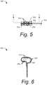
FIG. 5 illustrates abottom plan view 500 of thespring terminal 204. Thecontact surface 308 of thespring terminal 204 may includebifurcated contacts 502, which are separated by apredefined distance 504. Thebifurcated contacts 502 are configured to interface with the flat-wire conductors of thewiring 106. If debris prevents one of thebifurcated contacts 502 from contacting thewiring 106, the otherbifurcated contact 502 may still provide the connection to thewiring 106. - The
bifurcated contacts 502 each include anouter edge 506 and aninner edge 508 that contribute to maintaining contact with thewiring 106. Theinner edges 508 are separated by thepredefined distance 504 of the space between thebifurcated contacts 502. - One or both of the
bifurcated contacts 502 may include one or more protrusions 510 (e.g., bumps, darts, knurls, ridges, serrations, etc.) configured to improve electrical connection with thewiring 106 by increasing the surface area of thecontact surface 308. Additionally or alternatively, thebifurcated contacts 502 may include one or more indentations (e.g., notches, grooves, slots, channels, etc.) configured to improve electrical connection with thewiring 106 by increasing the surface area of thecontact surface 308. -
FIG. 6 illustrates asectional view 600 of the spring terminal fromFIG. 5 , taken along section line 6-6. In aspects, theprotrusions 510 on the contact surface of the spring terminal may have correspondingindentations 602 on aninterior surface 604 of thespring terminal 204. Theseindentations 602 may be formed during a manufacturing process of thespring terminal 204 that stamps the metal strip on theinterior surface 604 to form the protrusions on thecontact surface 308 prior to bending the metal strip to form thespring terminal 204. -
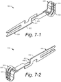
FIGS. 7-1 and 7-2 illustrate perspective views 700 and 710, respectively, of theelectrical connector 110. As illustrated inFIGS. 7-1 and 7-2 and as described above, theelectrical connector 110 includes anelongated body 302 with aspring terminal 204 at one end and a split-blade terminal 202 at an opposing end. Thespring terminal 204 is configured to interface with a flat-wire conductor 108 of an FC. In aspects, the spring terminal includesbifurcated contacts 502 with one ormore protrusions 510 and/or indentations (not shown). Theelongated body 302 includes one ormore bends 416 and/ornotches 422 to provide flexibility in multiple degrees of freedom. - The
electrical connector 110 can be manufactured using common methods of progressive metal forming. For example, a rectangular strip of metal can be stamped, cut, and bent to shape theelectrical connector 110. First, an appropriately-sized strip of metal can be stamped or cut to create the split-blade terminal 202, thenotches 422, theprotrusions 510, and the space between thebifurcated contacts 502. Then, theelongated body 302 can be bent to create thebend 416 and thespring terminal 204. -
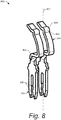
FIG. 8 illustrates a topfront perspective view 800 of another example implementation of theelectrical connector 110. In this illustrated example, theelectrical connector 110 includes the split-blade terminal 202 at one end, which hasprongs 306 configured to mate with a blade terminal or a pin terminal. At the opposing end, the electrical connector includes thespring terminal 204. Thespring terminal 204 in this example has an arcuate shape (e.g., curved L-shape) and is configured to interface with an FC that does not run perpendicular to alongitudinal axis 802 of theelectrical connector 110. Rather, thespring terminal 204 in this example has acontact surface 804 that is within a range of 30 to 60 degrees from thelongitudinal axis 802. In aspects, theelectrical connector 110 includes one or more bends (e.g., bend 806) such that thespring terminal 204 and the split-blade terminal 202 are rotated relative to one another about thelongitudinal axis 802 by approximately 90 degrees. Thespring terminal 204 also includes a protrusion, such asprotrusion 808. -
FIG. 9 illustrates an example implementation of thespring terminal 204 fromFIG. 8 connecting to the FC. View 900-1 illustrates thespring terminal 204 approaching the flat-wire conductors 108 of thewiring 106 in a direction corresponding to thelongitudinal axis 304 of theelectrical connector 110. In view 900-2, theelectrical connector 110 is pressed against the flat-wire conductors 108, based on a longitudinal compression force along thelongitudinal axis 304 of theelectrical connector 110. Due to the angle of the contact not being perpendicular to the compression force, theprotrusion 808 may slidably move along the flat-wire conductor 108 a short distance. This slidable movement may wipe away debris that might be on the flat-wire conductor 108, providing a clean surface to interface with thespring terminal 204. -
FIG. 10 illustrates a topfront perspective view 1000 of an example system in which thespring terminal 204 ofFIG. 8 can be implemented to connect to the FC. In the illustrated example, ahousing 1002 houses a pair ofelectrical connectors 110 such that thespring terminals 204 of theelectrical connectors 110 can be mated to aconnection area 1004 of thewiring 106, which may be a flexible circuit. Here, thespring terminals 204 contact the flat-wire conductors 108 (fromFIG. 1 ) exposed in theconnection area 1004. -
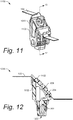
FIG. 11 illustrates a topfront perspective view 1100 of an example connector in which the spring terminal fromFIG. 8 can be used to connect with the FC. Here, thehousing 1002 is connected to aretainer 1102 on opposing sides of thewiring 106. Theretainer 1102 compresses thewiring 106 against thespring terminals 204 of theelectrical connectors 110 housed within thehousing 1002 and secures thewiring 106 in place, which maintains contact with theelectrical connectors 110. -
FIG. 12 illustrates asectional view 1200 of the connector inFIG. 11 , taken along section line 12-12. In thesectional view 1200, thespring terminal 204 is contacting thewiring 106 based on a compression force provided by thehousing 1002 and theretainer 1102 being fastened together on opposing sides of thewiring 106. The compression force is in a longitudinal direction of theelectrical connector 110. Thehousing 1002 includes an opening to allow an electrical component to mate with the split-blade terminal 202 of theelectrical connector 110.
Claims (15)
- An electrical connector for connecting to flat-wire conductors of a flexible circuit (FC), the electrical connector comprising:an elongated body having a longitudinal axis;a split-blade terminal having two prongs separated by a distance and configured to interface with an electrical terminal of an electrical device; anda spring terminal configured to mate with one or more of the flat-wire conductors within a connection area of the FC, the spring terminal and the split-blade terminal positioned on the longitudinal axis at opposing ends of the electrical connector.
- The electrical connector of claim 1, wherein the spring terminal comprises bifurcated contacts that are configured to interface with the one or more of the flat-wire conductors.
- The electrical connector of claim 2, wherein a contact surface of the bifurcated contacts defines a plane that is substantially perpendicular to the longitudinal axis of the elongated body.
- The electrical connector of claim 2, wherein a contact surface of the bifurcated contacts defines a plane that forms an acute angle relative to the FC to promote contact wipe when the bifurcated contacts are mated to the flat-wire conductors.
- The electrical connector of claim 2, wherein the bifurcated contacts include one or more protrusions on a contact surface that is configured to interface with the one or more of the flat-wire conductors.
- The electrical connector of claim 2, wherein the bifurcated contacts include one or more indentations on a contact surface that is configured to interface with the one or more of the flat-wire conductors.
- The electrical connector of claim 1, wherein the spring terminal has an approximate obround shape.
- The electrical connector of claim 1, wherein the spring terminal has an arcuate shape.
- The electrical connector of claim 1, wherein the elongated body comprises one or more bends or notches positioned between the spring terminal and the split-blade terminal, the one or more bends or notches enabling flexion in at least three degrees of freedom.
- The electrical connector of claim 1, wherein the elongated body comprises:
a flat strip of metal having a first portion defining a first plane and a second portion defining a second plane, the first plane and the second plane each being parallel to the longitudinal axis, the first plane substantially perpendicular to the second plane. - The electrical connector of claim 1, wherein the two prongs of the split-blade terminal are configured to mate with a pin terminal or a flat-blade terminal of the electrical device.
- The electrical connector of claim 1, wherein the spring terminal is configured to mate with the one or more of the flat-wire conductors within the connection area of the FC based on a compression force along the longitudinal axis.
- The electrical connector of claim 1, wherein the spring terminal comprises a contact surface configured to interface with the one or more of the flat-wire conductors of the FC, the contact surface defining a plane, the plane forming an angle with the flat-wire conductors in a range of 5 to 20 degrees.
- A system comprising:a housing that surrounds a portion of a flexible circuit (FC);a plurality of flat-wire conductors of the FC, the plurality of flat-wire conductors having an exposed section at a connection area of the FC that is positioned within the housing; anda plurality of electrical connectors supported within the housing, the plurality of electrical connectors each having a spring terminal at a first end and a split-blade terminal positioned at a second end that is opposite the first end, one or more of the plurality of electrical connectors abutting the exposed section of one or more of the flat-wire conductors based on a compression force, the split-blade terminal having two prongs separated by a distance and configured to interface with an electrical terminal of an electrical device.
- The system of claim 14, wherein the spring terminal of an electrical connector of the plurality of electrical connectors comprises bifurcated contacts that abut the exposed section of a flat-wire conductor of the plurality of flat-wire conductors.
Applications Claiming Priority (2)
| Application Number | Priority Date | Filing Date | Title |
|---|---|---|---|
| US202062956903P | 2020-01-03 | 2020-01-03 | |
| US17/124,782 US11411334B2 (en) | 2020-01-03 | 2020-12-17 | Electrical connector for connecting to flat-wire conductors of a flexible printed circuit |
Publications (2)
| Publication Number | Publication Date |
|---|---|
| EP3855574A2 true EP3855574A2 (en) | 2021-07-28 |
| EP3855574A3 EP3855574A3 (en) | 2021-10-20 |
Family
ID=73856980
Family Applications (1)
| Application Number | Title | Priority Date | Filing Date |
|---|---|---|---|
| EP20216809.2A Pending EP3855574A3 (en) | 2020-01-03 | 2020-12-23 | Electrical connector for connecting to flat-wire conductors of a flexible printed circuit |
Country Status (3)
| Country | Link |
|---|---|
| US (1) | US11411334B2 (en) |
| EP (1) | EP3855574A3 (en) |
| CN (1) | CN113161784B (en) |
Families Citing this family (6)
| Publication number | Priority date | Publication date | Assignee | Title |
|---|---|---|---|---|
| CN115799869A (en) * | 2020-09-14 | 2023-03-14 | 安波福技术有限公司 | Direct equipment electrical connection to flex circuits or other conductors |
| JP7522642B2 (en) * | 2020-11-18 | 2024-07-25 | 日本航空電子工業株式会社 | connector |
| CN113571935A (en) * | 2021-08-17 | 2021-10-29 | 长春捷翼汽车零部件有限公司 | Micro-vibration terminal, plug structure and motor vehicle |
| DE102022123912A1 (en) * | 2022-09-19 | 2024-03-21 | Oechsler Ag | Contact device, electrical component unit, method and use of a contact device in an electrical component unit |
| JP2024078683A (en) * | 2022-11-30 | 2024-06-11 | 日本航空電子工業株式会社 | Connector assembly and connection method |
| US12580356B2 (en) | 2023-08-01 | 2026-03-17 | Aptiv Technologies AG | Method of assembling an electrical connector and an electrical connector |
Citations (6)
| Publication number | Priority date | Publication date | Assignee | Title |
|---|---|---|---|---|
| US20020142663A1 (en) * | 2001-03-07 | 2002-10-03 | Tetsuo Takeyama | Contact terminal and card connector having the same |
| DE10007138C2 (en) * | 1999-02-18 | 2002-10-10 | Japan Aviation Electron | contact element |
| CN201616527U (en) * | 2008-09-30 | 2010-10-27 | 富士康(昆山)电脑接插件有限公司 | Conductive terminal |
| WO2012023507A1 (en) * | 2010-08-16 | 2012-02-23 | 矢崎総業株式会社 | Joint terminal and joint connector provided with joint terminal |
| DE102011078096A1 (en) * | 2011-06-27 | 2012-12-27 | Robert Bosch Gmbh | Direct plug-in element for establishing multi-surface direct plug connection at e.g. printed circuit board, of control device of motor vehicle, has direct contacts electrically fastened at cables by connecting devices |
| EP3392971A1 (en) * | 2017-04-21 | 2018-10-24 | Braun GmbH | Connector device with connector and assembly method |
Family Cites Families (21)
| Publication number | Priority date | Publication date | Assignee | Title |
|---|---|---|---|---|
| US2856592A (en) * | 1956-05-01 | 1958-10-14 | Gen Electric | Extension wiring system |
| US3796986A (en) * | 1972-07-03 | 1974-03-12 | Bell Telephone Labor Inc | Interconnection system for reusable gang-type connections between flexible printed circuitry and the like |
| US4040705A (en) * | 1976-04-12 | 1977-08-09 | Amp Incorporated | Coaxial ribbon cable connector |
| US4358172A (en) * | 1980-04-23 | 1982-11-09 | Thomas & Betts Corporation | Connector for electrical interconnection of circuit board and flat multiconductor cable |
| US4891019A (en) | 1989-03-03 | 1990-01-02 | Amp Incorporated | Electrical connector for interconnecting a printed circuit board to a ribbon cable |
| JP2001143795A (en) | 1999-11-12 | 2001-05-25 | Kyocera Elco Kk | Connector for fpc/ffc without soldering |
| US6579105B2 (en) * | 2001-11-01 | 2003-06-17 | Molex Incorporated | Electrical connector assembly |
| US6908326B2 (en) | 2003-08-08 | 2005-06-21 | J. S. T. Mfg. Co., Ltd. | Floating connector |
| JP4098290B2 (en) * | 2004-08-31 | 2008-06-11 | モレックス インコーポレーテッド | FFC connector |
| EP2685569B1 (en) * | 2006-11-02 | 2019-03-27 | TE Connectivity Corporation | Wire retention connector system |
| US7549884B2 (en) * | 2007-01-29 | 2009-06-23 | Samtec, Inc. | Probe having a field-replaceable tip |
| JP4963988B2 (en) * | 2007-03-01 | 2012-06-27 | モレックス インコーポレイテド | Terminal assembly and connector |
| JP5057592B2 (en) * | 2010-02-03 | 2012-10-24 | ヒロセ電機株式会社 | Circuit board electrical connector |
| US7980896B1 (en) * | 2010-08-05 | 2011-07-19 | Tyco Electronics Corporation | Electrical connector assembly |
| JP5792011B2 (en) * | 2011-09-26 | 2015-10-07 | 矢崎総業株式会社 | Flat cable waterproof connector structure and connection method thereof |
| US9065192B2 (en) * | 2013-09-19 | 2015-06-23 | Tyco Electronics Corporation | Power terminal connector |
| US8628335B1 (en) * | 2012-12-07 | 2014-01-14 | Tyco Electronics Corporation | Power terminal connector |
| EP3050162B1 (en) * | 2013-09-25 | 2018-10-24 | TE Connectivity Corporation | Electrical system |
| DE202015103779U1 (en) * | 2015-07-17 | 2016-10-18 | Wago Verwaltungsgesellschaft Mbh | Connectors |
| DE102017221490A1 (en) * | 2017-11-30 | 2019-06-06 | Eberspächer Catem Gmbh & Co. Kg | Electric heater |
| US11955747B2 (en) * | 2020-01-03 | 2024-04-09 | Aptiv Technologies Limited | Watertight electrical connection system to flat-wire conductors of a flexible printed circuit |
-
2020
- 2020-12-17 US US17/124,782 patent/US11411334B2/en active Active
- 2020-12-23 EP EP20216809.2A patent/EP3855574A3/en active Pending
- 2020-12-30 CN CN202011608486.9A patent/CN113161784B/en active Active
Patent Citations (6)
| Publication number | Priority date | Publication date | Assignee | Title |
|---|---|---|---|---|
| DE10007138C2 (en) * | 1999-02-18 | 2002-10-10 | Japan Aviation Electron | contact element |
| US20020142663A1 (en) * | 2001-03-07 | 2002-10-03 | Tetsuo Takeyama | Contact terminal and card connector having the same |
| CN201616527U (en) * | 2008-09-30 | 2010-10-27 | 富士康(昆山)电脑接插件有限公司 | Conductive terminal |
| WO2012023507A1 (en) * | 2010-08-16 | 2012-02-23 | 矢崎総業株式会社 | Joint terminal and joint connector provided with joint terminal |
| DE102011078096A1 (en) * | 2011-06-27 | 2012-12-27 | Robert Bosch Gmbh | Direct plug-in element for establishing multi-surface direct plug connection at e.g. printed circuit board, of control device of motor vehicle, has direct contacts electrically fastened at cables by connecting devices |
| EP3392971A1 (en) * | 2017-04-21 | 2018-10-24 | Braun GmbH | Connector device with connector and assembly method |
Also Published As
| Publication number | Publication date |
|---|---|
| US11411334B2 (en) | 2022-08-09 |
| US20210210882A1 (en) | 2021-07-08 |
| EP3855574A3 (en) | 2021-10-20 |
| CN113161784A (en) | 2021-07-23 |
| CN113161784B (en) | 2026-03-24 |
Similar Documents
| Publication | Publication Date | Title |
|---|---|---|
| US11411334B2 (en) | Electrical connector for connecting to flat-wire conductors of a flexible printed circuit | |
| CN102195162B (en) | connector device | |
| US10630004B2 (en) | Connection assisting member and circuit board assembly | |
| WO2021145447A1 (en) | Terminal | |
| EP2560242A1 (en) | Electronic component | |
| JPH11273806A (en) | Electrical connector | |
| US20150056830A1 (en) | Electrical Connector | |
| JP5543831B2 (en) | Electrical equipment | |
| WO2023248203A1 (en) | Connector, connector pair, and method of manufacturing connector | |
| EP1126553A2 (en) | Flat cable Terminal | |
| CN108232488B (en) | Connector and method of manufacturing the connector | |
| EP2963739B1 (en) | Dual thickness double-ended male blade terminal and method of manufacturing it | |
| JP2025034791A (en) | Connector Assembly | |
| EP1143577B1 (en) | Conductive element and manufacturing method thereof | |
| CN2513243Y (en) | Electric connector | |
| CN110416787A (en) | Contact, connector and attachment device | |
| JP4021397B2 (en) | Connection terminal and joint connector using the connection terminal | |
| CN116261815B (en) | Terminal unit | |
| WO2023017766A1 (en) | Connector and electronic device | |
| US20220115802A1 (en) | Terminal | |
| JP2024524705A (en) | Electrical connection structure for conductors formed on a glass surface | |
| US7544098B2 (en) | Connector having a stopper mechanism defining a movable range of a housing receiving a connection object | |
| US4533206A (en) | Flexible printed circuit connector | |
| US12586937B2 (en) | Connector and electronic device | |
| JP7637103B2 (en) | Connector and connector device |
Legal Events
| Date | Code | Title | Description |
|---|---|---|---|
| PUAI | Public reference made under article 153(3) epc to a published international application that has entered the european phase |
Free format text: ORIGINAL CODE: 0009012 |
|
| STAA | Information on the status of an ep patent application or granted ep patent |
Free format text: STATUS: THE APPLICATION HAS BEEN PUBLISHED |
|
| AK | Designated contracting states |
Kind code of ref document: A2 Designated state(s): AL AT BE BG CH CY CZ DE DK EE ES FI FR GB GR HR HU IE IS IT LI LT LU LV MC MK MT NL NO PL PT RO RS SE SI SK SM TR |
|
| PUAL | Search report despatched |
Free format text: ORIGINAL CODE: 0009013 |
|
| AK | Designated contracting states |
Kind code of ref document: A3 Designated state(s): AL AT BE BG CH CY CZ DE DK EE ES FI FR GB GR HR HU IE IS IT LI LT LU LV MC MK MT NL NO PL PT RO RS SE SI SK SM TR |
|
| RIC1 | Information provided on ipc code assigned before grant |
Ipc: H01R 31/06 20060101ALN20210914BHEP Ipc: H01R 13/52 20060101ALN20210914BHEP Ipc: H01R 13/627 20060101ALN20210914BHEP Ipc: H01R 105/00 20060101ALN20210914BHEP Ipc: H01R 13/11 20060101ALN20210914BHEP Ipc: H01R 12/77 20110101ALI20210914BHEP Ipc: H01R 13/24 20060101AFI20210914BHEP Ipc: H01R 43/16 20060101ALN20210914BHEP |
|
| STAA | Information on the status of an ep patent application or granted ep patent |
Free format text: STATUS: REQUEST FOR EXAMINATION WAS MADE |
|
| 17P | Request for examination filed |
Effective date: 20220420 |
|
| RBV | Designated contracting states (corrected) |
Designated state(s): AL AT BE BG CH CY CZ DE DK EE ES FI FR GB GR HR HU IE IS IT LI LT LU LV MC MK MT NL NO PL PT RO RS SE SI SK SM TR |
|
| RAP3 | Party data changed (applicant data changed or rights of an application transferred) |
Owner name: APTIV TECHNOLOGIES LIMITED |
|
| STAA | Information on the status of an ep patent application or granted ep patent |
Free format text: STATUS: EXAMINATION IS IN PROGRESS |
|
| 17Q | First examination report despatched |
Effective date: 20231129 |
|
| RAP1 | Party data changed (applicant data changed or rights of an application transferred) |
Owner name: APTIV TECHNOLOGIES AG |
|
| RAP3 | Party data changed (applicant data changed or rights of an application transferred) |
Owner name: APTIV TECHNOLOGIES AG |