EP3855558A1 - Battery cell, battery module, battery pack, device using battery cell as power supply, and method for assembling battery cell - Google Patents
Battery cell, battery module, battery pack, device using battery cell as power supply, and method for assembling battery cell Download PDFInfo
- Publication number
- EP3855558A1 EP3855558A1 EP19914697.8A EP19914697A EP3855558A1 EP 3855558 A1 EP3855558 A1 EP 3855558A1 EP 19914697 A EP19914697 A EP 19914697A EP 3855558 A1 EP3855558 A1 EP 3855558A1
- Authority
- EP
- European Patent Office
- Prior art keywords
- battery cell
- tab
- support portion
- main body
- support
- Prior art date
- Legal status (The legal status is an assumption and is not a legal conclusion. Google has not performed a legal analysis and makes no representation as to the accuracy of the status listed.)
- Granted
Links
Images





Classifications
-
- H—ELECTRICITY
- H01—ELECTRIC ELEMENTS
- H01M—PROCESSES OR MEANS, e.g. BATTERIES, FOR THE DIRECT CONVERSION OF CHEMICAL ENERGY INTO ELECTRICAL ENERGY
- H01M50/00—Constructional details or processes of manufacture of the non-active parts of electrochemical cells other than fuel cells, e.g. hybrid cells
- H01M50/20—Mountings; Secondary casings or frames; Racks, modules or packs; Suspension devices; Shock absorbers; Transport or carrying devices; Holders
- H01M50/204—Racks, modules or packs for multiple batteries or multiple cells
-
- H—ELECTRICITY
- H01—ELECTRIC ELEMENTS
- H01M—PROCESSES OR MEANS, e.g. BATTERIES, FOR THE DIRECT CONVERSION OF CHEMICAL ENERGY INTO ELECTRICAL ENERGY
- H01M50/00—Constructional details or processes of manufacture of the non-active parts of electrochemical cells other than fuel cells, e.g. hybrid cells
- H01M50/10—Primary casings; Jackets or wrappings
- H01M50/172—Arrangements of electric connectors penetrating the casing
- H01M50/174—Arrangements of electric connectors penetrating the casing adapted for the shape of the cells
- H01M50/176—Arrangements of electric connectors penetrating the casing adapted for the shape of the cells for prismatic or rectangular cells
-
- H—ELECTRICITY
- H01—ELECTRIC ELEMENTS
- H01M—PROCESSES OR MEANS, e.g. BATTERIES, FOR THE DIRECT CONVERSION OF CHEMICAL ENERGY INTO ELECTRICAL ENERGY
- H01M50/00—Constructional details or processes of manufacture of the non-active parts of electrochemical cells other than fuel cells, e.g. hybrid cells
- H01M50/10—Primary casings; Jackets or wrappings
- H01M50/102—Primary casings; Jackets or wrappings characterised by their shape or physical structure
- H01M50/103—Primary casings; Jackets or wrappings characterised by their shape or physical structure prismatic or rectangular
-
- H—ELECTRICITY
- H01—ELECTRIC ELEMENTS
- H01M—PROCESSES OR MEANS, e.g. BATTERIES, FOR THE DIRECT CONVERSION OF CHEMICAL ENERGY INTO ELECTRICAL ENERGY
- H01M50/00—Constructional details or processes of manufacture of the non-active parts of electrochemical cells other than fuel cells, e.g. hybrid cells
- H01M50/10—Primary casings; Jackets or wrappings
- H01M50/147—Lids or covers
- H01M50/148—Lids or covers characterised by their shape
-
- H—ELECTRICITY
- H01—ELECTRIC ELEMENTS
- H01M—PROCESSES OR MEANS, e.g. BATTERIES, FOR THE DIRECT CONVERSION OF CHEMICAL ENERGY INTO ELECTRICAL ENERGY
- H01M50/00—Constructional details or processes of manufacture of the non-active parts of electrochemical cells other than fuel cells, e.g. hybrid cells
- H01M50/10—Primary casings; Jackets or wrappings
- H01M50/147—Lids or covers
- H01M50/148—Lids or covers characterised by their shape
- H01M50/152—Lids or covers characterised by their shape for cells having curved cross-section, e.g. round or elliptic
-
- H—ELECTRICITY
- H01—ELECTRIC ELEMENTS
- H01M—PROCESSES OR MEANS, e.g. BATTERIES, FOR THE DIRECT CONVERSION OF CHEMICAL ENERGY INTO ELECTRICAL ENERGY
- H01M50/00—Constructional details or processes of manufacture of the non-active parts of electrochemical cells other than fuel cells, e.g. hybrid cells
- H01M50/10—Primary casings; Jackets or wrappings
- H01M50/172—Arrangements of electric connectors penetrating the casing
-
- H—ELECTRICITY
- H01—ELECTRIC ELEMENTS
- H01M—PROCESSES OR MEANS, e.g. BATTERIES, FOR THE DIRECT CONVERSION OF CHEMICAL ENERGY INTO ELECTRICAL ENERGY
- H01M50/00—Constructional details or processes of manufacture of the non-active parts of electrochemical cells other than fuel cells, e.g. hybrid cells
- H01M50/10—Primary casings; Jackets or wrappings
- H01M50/183—Sealing members
-
- H—ELECTRICITY
- H01—ELECTRIC ELEMENTS
- H01M—PROCESSES OR MEANS, e.g. BATTERIES, FOR THE DIRECT CONVERSION OF CHEMICAL ENERGY INTO ELECTRICAL ENERGY
- H01M50/00—Constructional details or processes of manufacture of the non-active parts of electrochemical cells other than fuel cells, e.g. hybrid cells
- H01M50/10—Primary casings; Jackets or wrappings
- H01M50/183—Sealing members
- H01M50/184—Sealing members characterised by their shape or structure
-
- H—ELECTRICITY
- H01—ELECTRIC ELEMENTS
- H01M—PROCESSES OR MEANS, e.g. BATTERIES, FOR THE DIRECT CONVERSION OF CHEMICAL ENERGY INTO ELECTRICAL ENERGY
- H01M50/00—Constructional details or processes of manufacture of the non-active parts of electrochemical cells other than fuel cells, e.g. hybrid cells
- H01M50/10—Primary casings; Jackets or wrappings
- H01M50/183—Sealing members
- H01M50/186—Sealing members characterised by the disposition of the sealing members
- H01M50/188—Sealing members characterised by the disposition of the sealing members the sealing members being arranged between the lid and terminal
-
- H—ELECTRICITY
- H01—ELECTRIC ELEMENTS
- H01M—PROCESSES OR MEANS, e.g. BATTERIES, FOR THE DIRECT CONVERSION OF CHEMICAL ENERGY INTO ELECTRICAL ENERGY
- H01M50/00—Constructional details or processes of manufacture of the non-active parts of electrochemical cells other than fuel cells, e.g. hybrid cells
- H01M50/20—Mountings; Secondary casings or frames; Racks, modules or packs; Suspension devices; Shock absorbers; Transport or carrying devices; Holders
- H01M50/204—Racks, modules or packs for multiple batteries or multiple cells
- H01M50/207—Racks, modules or packs for multiple batteries or multiple cells characterised by their shape
- H01M50/209—Racks, modules or packs for multiple batteries or multiple cells characterised by their shape adapted for prismatic or rectangular cells
-
- H—ELECTRICITY
- H01—ELECTRIC ELEMENTS
- H01M—PROCESSES OR MEANS, e.g. BATTERIES, FOR THE DIRECT CONVERSION OF CHEMICAL ENERGY INTO ELECTRICAL ENERGY
- H01M50/00—Constructional details or processes of manufacture of the non-active parts of electrochemical cells other than fuel cells, e.g. hybrid cells
- H01M50/50—Current conducting connections for cells or batteries
- H01M50/531—Electrode connections inside a battery casing
-
- H—ELECTRICITY
- H01—ELECTRIC ELEMENTS
- H01M—PROCESSES OR MEANS, e.g. BATTERIES, FOR THE DIRECT CONVERSION OF CHEMICAL ENERGY INTO ELECTRICAL ENERGY
- H01M50/00—Constructional details or processes of manufacture of the non-active parts of electrochemical cells other than fuel cells, e.g. hybrid cells
- H01M50/50—Current conducting connections for cells or batteries
- H01M50/543—Terminals
-
- H—ELECTRICITY
- H01—ELECTRIC ELEMENTS
- H01M—PROCESSES OR MEANS, e.g. BATTERIES, FOR THE DIRECT CONVERSION OF CHEMICAL ENERGY INTO ELECTRICAL ENERGY
- H01M50/00—Constructional details or processes of manufacture of the non-active parts of electrochemical cells other than fuel cells, e.g. hybrid cells
- H01M50/50—Current conducting connections for cells or batteries
- H01M50/572—Means for preventing undesired use or discharge
- H01M50/584—Means for preventing undesired use or discharge for preventing incorrect connections inside or outside the batteries
- H01M50/586—Means for preventing undesired use or discharge for preventing incorrect connections inside or outside the batteries inside the batteries, e.g. incorrect connections of electrodes
-
- H—ELECTRICITY
- H01—ELECTRIC ELEMENTS
- H01M—PROCESSES OR MEANS, e.g. BATTERIES, FOR THE DIRECT CONVERSION OF CHEMICAL ENERGY INTO ELECTRICAL ENERGY
- H01M50/00—Constructional details or processes of manufacture of the non-active parts of electrochemical cells other than fuel cells, e.g. hybrid cells
- H01M50/50—Current conducting connections for cells or batteries
- H01M50/572—Means for preventing undesired use or discharge
- H01M50/584—Means for preventing undesired use or discharge for preventing incorrect connections inside or outside the batteries
- H01M50/59—Means for preventing undesired use or discharge for preventing incorrect connections inside or outside the batteries characterised by the protection means
- H01M50/593—Spacers; Insulating plates
-
- H—ELECTRICITY
- H01—ELECTRIC ELEMENTS
- H01M—PROCESSES OR MEANS, e.g. BATTERIES, FOR THE DIRECT CONVERSION OF CHEMICAL ENERGY INTO ELECTRICAL ENERGY
- H01M2220/00—Batteries for particular applications
- H01M2220/20—Batteries in motive systems, e.g. vehicle, ship, plane
-
- Y—GENERAL TAGGING OF NEW TECHNOLOGICAL DEVELOPMENTS; GENERAL TAGGING OF CROSS-SECTIONAL TECHNOLOGIES SPANNING OVER SEVERAL SECTIONS OF THE IPC; TECHNICAL SUBJECTS COVERED BY FORMER USPC CROSS-REFERENCE ART COLLECTIONS [XRACs] AND DIGESTS
- Y02—TECHNOLOGIES OR APPLICATIONS FOR MITIGATION OR ADAPTATION AGAINST CLIMATE CHANGE
- Y02E—REDUCTION OF GREENHOUSE GAS [GHG] EMISSIONS, RELATED TO ENERGY GENERATION, TRANSMISSION OR DISTRIBUTION
- Y02E60/00—Enabling technologies; Technologies with a potential or indirect contribution to GHG emissions mitigation
- Y02E60/10—Energy storage using batteries
Definitions
- the insulating support plate further comprises a carrying portion, the carrying portion protrudes in a direction approaching the connecting sheet relative to the first supporting portion, the carrying portion and the connecting sheet together limit a position of the insulating member.
- a battery module comprising said battery cell.
- laser welding may be used.
- impurities such as metal shavings
- the impurities may fall into the third groove 421 of the second connecting portion 42, and at the same time, impurities from the external environment may also fall into the third groove 421.
- the impurities may fall into the electrode assembly 20, thereby causing a short circuit risk.
Landscapes
- Chemical & Material Sciences (AREA)
- Chemical Kinetics & Catalysis (AREA)
- Electrochemistry (AREA)
- General Chemical & Material Sciences (AREA)
- Connection Of Batteries Or Terminals (AREA)
- Battery Mounting, Suspending (AREA)
- Sealing Battery Cases Or Jackets (AREA)
Abstract
Description
- The present disclosure relates to a battery cell, battery module, battery pack, device using the battery cell as a power source, and assembling method of the battery cell.
- At present, batteries are widely used in portable electronic devices (such as mobile phones, digital cameras, laptops, etc.), electric vehicles (such as electric bicycles, electric cars, etc.) and large and medium-sized electric energy storage facilities, and reliability of batteries is increasingly important.
- A battery comprises a battery core. A tab is provided on top of the battery core. During assembly, in order to avoid short circuit between the tab and the bare core, an insulator is usually required to be provided on the core. In the related art, the insulator entirely is flat, which is prone to compress the tab, causing damages to the tab, and reducing the service life of the battery.
- It should be noted that information revealed in the portion subtitled under "Background Art" of the present disclosure is only intended to promote understanding of the general background of the present disclosure, and should not be considered as an acknowledgment or any form of suggestion that the information constitutes the state of art that is already known to those skilled in the art.
- The embodiments of the present disclosure provide a battery cell, battery module, battery pack, device using the battery cell as power source, and assembling method of the battery cell to reduce to compress the tab and increase the service life of the battery.
- According to one aspect of the present disclosure, a battery cell is provided, the batter cell comprising:
- an electrode assembly comprising a main body portion and a tab connected to the main body portion; and
- an insulating support plate comprising a first support portion and a second support portion connected to the first support portion, the first support portion protrudes in a direction approaching the main body portion relative to the second support portion such that a first gap is formed between the second support portion and the main body portion, and at least a portion of the tab is located in the first gap.
- In some embodiments, the tab comprises a first tab section connected to the main body portion and a second tab section located on a side of the first tab section away from the main body portion, the first tab section is located in the first gap.
- In some embodiments, the second tab section is located on a side of the second support portion away from the first tab section.
- In some embodiments, the first support portion abuts against the main body portion.
- In some embodiments, the first support portion and the second support portion are both flat, and the first support portion and the second support portion are parallel to each other.
- In some embodiments, one or more second support portions are provided on each of two sides of the first support portion.
- In some embodiments, each of two sides of the first support portion is provided with two second support portions, and the there is a second gap between the two second support portions on the same side of the first support portion.
- In some embodiments, the battery cell further comprises a cover plate assembly and a case in which the electrode assembly and the insulating support plate are disposed, the case has an opening, the cover plate assembly is configured to seal the opening, the first support portion is provided with a hook, and the cover plate assembly is provided with a first groove, wherein the hook is inserted into the first groove to connect the insulating support plate and the cover plate assembly.
- In some embodiments, the first support portion is provided with a second groove, and the hook is disposed in the second groove.
- In some embodiments, the battery cell further comprises an electrode terminal and a connecting sheet, and the connecting sheet is configured to electrically connect the tab and the electrode terminal.
- In some embodiments, the battery cell further comprises an insulating member disposed between the insulation support plate and the connecting sheet.
- In some embodiments, both the insulating support plate and the connecting sheet abut against the insulating member.
- In some embodiments, the insulating support plate further comprises a carrying portion, the carrying portion protrudes in a direction approaching the connecting sheet relative to the first supporting portion, the carrying portion and the connecting sheet together limit a position of the insulating member.
- According to another aspect of the present disclosure, a battery module is provided, the batter module comprising said battery cell.
- The present disclosure also provides a battery pack including said battery module.
- The present disclosure also provides a device using a battery cell as a power source, the device comprising said battery cell.
- The present disclosure also provides an assembly method of said battery cell, comprising:
- placing an insulating support plate on one side of the main body portion and placing the first support portion closer to the main body portion than the second support portion to form a first gap is formed between the second support portion and the main body portion; and
- folding the tab to make at least a portion of the tab located in the first gap.
- According to the above technical solution, in the embodiments of the present disclosure, the first support portion of the insulating support plate protrudes in a direction approaching the main body portion relative to the second support portion to form a first gap between the second support portion and the main body portion, wherein at least a portion of the tab is disposed in the first gap. As a space for accommodating at least a portion of the tab, the first gap can protect the tab, prevent the tab from being compressed, reduce damages to the tab, and increase the service life of the battery.
- By means of the detailed description below of exemplary embodiments of the present disclosure with reference to the drawing attached thereto, further features and advantages of the present disclosure will become clearer.
- In order to more clearly explain the embodiments of the present disclosure or the technical solutions in the prior art, drawings used in the description of the embodiments or the prior art will be briefly described below. Obviously, the drawings in the following description are only some embodiments of the present disclosure. Those skilled in the art can obtain further embodiments and their drawings according to the embodiments shown in these drawings without any creative effort.
-
FIG. 1 is a schematic structural view of an embodiment of a device using a battery cell as a power source according to the present disclosure. -
FIG. 2 is a schematic structural view of an embodiment of a battery pack according to the present disclosure. -
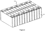
FIG. 3 is a schematic structural view of an embodiment of a battery module according to the present disclosure. -
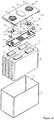
FIG. 4 is an explosive view of an embodiment of a battery cell according to the present disclosure. -
FIG. 5 is a schematic structural view of an embodiment of a tab in an embodiment of a battery cell according to the present disclosure. -
FIG. 6 is a sectional view of the embodiment as shown inFIG. 4 . -
FIG. 7 is a schematic structural view of a portion of an insulating support plate in an embodiment of a battery cell according to the present disclosure. -
FIG. 8 is a bottom view of a cover plate assembly in an embodiment of a battery cell according to the present disclosure. -
FIG. 9 is a schematic structural view of an insulating support plate in an embodiment of a battery cell according to the present disclosure. -
FIG. 10 is an explosive view of another embodiment of a battery cell according to the present disclosure. -
FIG. 11 is a sectional view of a further embodiment of a battery cell according to the present disclosure. -
FIG. 12 is a sectional view of a further yet embodiment of a battery cell according to the present disclosure. -
FIG. 13 is an extended view of an embodiment of a battery cell of the present disclosure. - 100. battery cell; 200. vehicle main body; 300. battery pack; 310. tank cover; 320. tank body; 330. batter module; 10. case; 11. opening; 20. electrode assembly; 21. tab; 22. main body portion; 211. first tab section; 212. second tab section; 213. third tab section; 214. tab seat; 30. cover plate assembly; 31. electrode terminal; 32. cover plate; 33. explosion-proof valve; 34. insulating side plate; 35. first groove; 36. second hole; 37. insulating baffle; 40. connecting sheet; 41. first connecting portion; 42. second connecting portion; 421. third groove; 43. connecting block; 44. first hole; 50. insulating support plate; 51. first support portion; 52. second support portion; 53. carrying portion; 531. fourth groove; 532. third hole; 54. hook; 541. first engaging portion; 542. second engaging portion; 5411. support rod; 5412. chuck; 55. second groove; 56. fourth hole; 57. fifth hole; 58. sixth hole; 60. insulating member.
- With reference to the figures of the embodiments of the present disclosure, a clear and complete description is given below for the technical solutions of the embodiments of the present disclosure. Obviously, the embodiments described below are only part of the embodiments, rather than all of the embodiments. The below description of at least one exemplary embodiment is actually only illustrative and cannot be taken as any restriction over the present disclosure and its application or use. All other embodiments that can be obtained by a person skilled in the art based on the embodiments of the present disclosure without any creative effort are included in the protection scope of the present disclosure.
- In the description of the present disclosure, it should be understood that the use of words such as "first" and "second" to define parts is only for the convenience of distinguishing the corresponding parts. The above words neither indicate, unless otherwise stated, sequential or primary and secondary relationships, nor have any other special meanings, and therefore cannot be understood as limiting the scope of protection of this disclosure.
- In the present disclosure, "more/a plurality of" refers to two or more (including two), and similarly, "more/a plurality of groups" refers to two or more groups (including two).
- Besides, when an element is referred to as being "on" another element, it can be directly on the other element, or indirectly on the other element with one or more intermediate elements interposed therebetween. Besides, when an element is referred to as being "connected to" another element, it can be directly connected to the other element, or indirectly connected to the other element with one or more intermediate elements interposed therebetween.
- For technology, process and apparatus already known by a person skilled in the related art, detailed discussion may not be given, but if appropriate, such technology, process and apparatus should be regarded as part of the patented specification.
- Technical features involved in the different embodiments of the present disclosure described below can be combined with each other as long as they do not constitute a conflict with each other.
- Referring to
Fig. 1 , the present disclosure provides a device using abattery cell 100 as a power source. The device using abattery cell 100 as a power source comprises thebattery cell 100 and a driver configured to provide a driving force to the device, wherein thebattery cell 100 is configured to provide electrical energy to the driver. The driving force of the device can be entirely electric energy, or partly electric energy and partly another energy source (such as mechanical energy). For example, the device may also include a power source such as an engine or the like that provides mechanical energy. Any device that uses thebattery cell 100 as a power source falls within the protection scope of the present disclosure. - In the embodiment as shown in
FIG. 1 , the device using thebattery cell 100 as a power source is a vehicle, and in another embodiments, the device using thebattery cell 100 as a power source may be a movable device such as a ship, a small aircraft or the like. When the device using thebattery cell 100 as a power source is a vehicle, the vehicle may be a new energy vehicle. The new energy vehicle can be a pure electric vehicle, a hybrid vehicle or a range extender. - Referring to
FIG. 1 , the vehicle includes abattery cell 100 and avehicle body 200, wherein thebattery cell 100 is disposed inside thevehicle body 200. Thevehicle body 200 is further provided with a driving motor, wherein the driving motor is electrically connected to thebattery cell 100 which provides power to the driving motor, and the driving motor is connected to wheels of thevehicle body 200 through a transmission mechanism so as to drive the vehicle. Particularly, thebattery cell 100 may be horizontally disposed on a bottom of thevehicle body 200. - Specially, referring to
FIG. 2 andFIG. 3 , a plurality ofbattery cells 100 may constitute abattery module 330. Thebattery module 330 is mounted in atank 320 and thetank 320 is sealed by atank cover 310 to form abattery pack 300. Thebattery pack 300 has a high energy storage capacity, which can improve the endurance of the device using thebattery cell 100 as a power source. Thetank 320 and thetank cover 310 are connected in a detachable manner to facilitate replacement of thebattery module 330. - Structure of the embodiment of the battery cell according to the present disclosure will be described below with reference to
FIGS. 4 to 13 . - Referring to
FIG. 4 , thebattery cell 100 comprises acase 10, anelectrode assembly 20, acover plate assembly 30, a connectingsheet 40, and an insulatingsupport plate 50. - An
opening 11 is provided on the top of thecase 10. Theelectrode assembly 20, the connectingsheet 40 and the insulatingsupport plate 50 are all disposed inside thecase 10, and thecover plate assembly 30 is configured to close theopening 11 of thecase 10. The insulatingsupport plate 50 is positioned above theelectrode assembly 20, theconnection piece 40 is positioned above the insulatingsupport plate 50, and the insulatingsupport plate 50 is connected to thecase 10. - There are various options for the shape of the
case 10. In the embodiment shown inFIG. 4 , the shape of thecase 10 is a cuboid, which matches a shape of thebattery cell 100. - The
electrode assembly 20 includes atab 21 and amain body portion 22, and thetab 21 is connected to themain body portion 22. Theelectrode assembly 20 includes at least twotabs 21, which are a positive electrode tab and a negative electrode tab, respectively. Twomain body portions 22 may share a same group of a positive electrode tab and a negative electrode tab. - In the embodiment shown in
FIG. 4 , theelectrode assembly 20 comprises fourtabs 21 and fourmain body portions 22, wherein the twomain body portions 22 share onepositive electrode tab 21 and onenegative electrode tab 21, and the other twobody portions 22 share anotherpositive electrode tab 21 and anothernegative electrode tab 21. Fourmain body portions 22 are placed in asingle case 10. - The
cover plate assembly 30 compriseselectrode terminals 31, acover plate 32, an explosion-proof valve 33, and an insulatingside plate 34. Theelectrode terminal 31 is mounted on thecover plate 32, and on two sides of thecover plate 32 are mounted with the insulatingplate 34. The explosion-proof valve 33 is disposed on thecover plate 32 and between twoelectrode terminals 31. The explosion-proof valve 33 is also called as a pressure relief valve, which is configured to release part of a pressure when the pressure inside thebattery cell 100 reaches a preset value to prevent thebattery cell 100 from explosion. - The connecting
sheet 40 comprises a first connectingportion 41 connected to thetab 21 and a second connectingportion 42 connected to theelectrode terminal 31. - In the embodiment shown in
FIG. 4 , thebattery cell 100 includes two connectingsheets 40 and twoelectrode terminals 31, wherein the first connectingportion 41 of one of the two connectingsheets 40 is connected to said twopositive electrode tabs 21, and the second connectingportion 42 of said one of the two connectingsheets 40 is connected to thepositive electrode terminal 31; the first connectingportion 41 of the other one of the two connectingsheets 40 is connected to said twonegative electrode tabs 21, and the second connectingportion 42 of said the other one of the two connectingsheets 40 is connected to thenegative electrode terminal 31. - The first connecting
portion 41 is entirely U-shaped, and the two connectingsheets 40 are oppositely arranged such that the U-shaped openings of the two first connectingportions 41 are opposite to each other. The second connectingportion 42 protrudes from the first connectingportion 41 in a direction approaching thecover plate assembly 30 so as to be connected to theelectrode terminal 31. The shape of the second connectingportion 42 is a circular to match a shape of theelectrode terminal 31. - Each of two sides of an intermediate connecting section of the first connecting
portion 41 is provided with a connectingblock 43 to facilitate connection of the first connectingportion 41 to thetab 21 and also facilitate positioning of the connectingsheets 40. The first connectingportion 41 of one of the connectingsheets 40 is provided with twofirst holes 44 so as to distinguish the two connectingsheets 40 and facilitate positioning of the connectingsheets 40. - The insulating
support plate 50 comprises afirst support portion 51, asecond support portion 52 and a carryingportion 53, the first support portion protrudes in a direction approaching the main body portion relative to the second support portion such that a first gap formed between thesecond support portion 52 and themain body portion 22, and at least a portion of thetab 21 is located in the first gap. As a space for accommodating at least a portion of the tab, the first gap effectively protects thetab 21, prevents thetab 21 from being compressed, reduces damages to thetab 21, and increases the service life of the battery. - Referring to
FIG. 5 , thetab 21 comprises afirst tab section 211 connected to themain body section 22 and asecond tab section 212 located on a side of thefirst tab section 211 away from themain body portion 22, thefirst tab section 211 is located in the first gap. - The
tab 21 further comprises athird tab section 213 connected between thefirst tab section 211 and thesecond tab section 212. - In the embodiment shown in
FIG. 5 , thefirst tab section 211 and thesecond tab section 212 are arranged in parallel, and thethird tab section 213 are perpendicularly arranged relative to thefirst tab section 211 and thesecond tab section 212. Thetab 21 is bent to form a structure with an opening on a side opposite to thethird tab section 213. In another embodiments, there may be other options for the shape of thetab 21 after bending. - The
tab 21 further comprises atab seat 214 connected to themain body portion 22, and thefirst tab section 211 is connected to thetab seat 214. By providing thetab seat 214, reliability of connection of thetab 21 with themain body portion 22 can be improved, and thetab 21 can be prevented from being broken during the bending process. - The
first tab section 211, thesecond tab section 212, thethird tab section 213 and thetab seat 214 can be separate from one another but connected together or can be formed integrally. - Referring to
FIG. 6 , thesecond tab section 212 is located on a side of thesecond support portion 52 away from thefirst tab portion 211 so as to electrically connect thesecond tab section 212 and the first connectingportion 41. Thesecond support portion 52 is located between thefirst tab section 211 and thesecond tab section 212. By providing thesecond support portion 52, thefirst tab section 211 can be well protected from being compressed while not affecting the connection between thesecond tab section 212 and the connectingsheet 40. - The
first support portion 51 and themain body portion 22 can be in direct contact or indirect contact, that is, an intermediate member can be provided between thefirst support portion 51 and themain body portion 22. - In the embodiment shown in
FIG. 6 , thefirst support portion 51 and themain body portion 22 are in direct contact with each other, which can not only produce a supporting and insulating effect, but also eliminate an intermediate connecting member, decrease a size of thebattery cell 100 and reduce a weight of thebattery cell 100. - The
first support portion 51 abuts themain body portion 22. Thefirst support portion 51 can be in contact but not connected with themain body portion 22, or thefirst support portion 51 can be in contact and connected with themain body portion 22. - The
first support portion 51 and thesecond support portion 52 are both flat, and thefirst support portion 51 and thesecond support portion 51 are parallel to each other. Such a structure has good stability and is easy to be assembled. - One or more second support portions are provided on each of two sides of the
first support portion 51 so as to facilitate providing protection to thetab 21 on each of two sides of thefirst support portion 51. - In the embodiment as shown in
Figs. 4 and6 , each of two sides of thefirst support portion 51 is provided with twosecond support portions 52, and there is a second gap between the two second support portions on the same side of thefirst support portion 51. Advantage of such an arrangement lies in that firstly, it can prevent mis-conduction between the positive and negative electrodes; and secondly, when a flame-retardant device is provided in the second gap, it can reduce an influence thereof on a flame-retardant effect of the flame-retardant device. - Referring to
FIG. 6 , the second connectingportion 42 protrudes in a direction approaching thecover plate assembly 30 relative to the first connectingportion 41 such that athird groove 421 is formed on a side of the second connectingportion 42 away from thecover plate assembly 30. The carryingportion 53 protrudes in a direction approaching thecover plate assembly 30 relative to thefirst support portion 51 such that afourth groove 531 is formed on a side of the carryingportion 53 away from thecover plate assembly 30. Thethird groove 421 and thefourth groove 531 can be filled with some breathable material as support. - Referring to
FIGS. 7 and 8 , in order to facilitate connection between thecover plate assembly 30 and the insulatingsupport plate 50, ahook 54 is provided on thefirst support portion 51, and afirst groove 35 is provided on thecover plate 32 of thecover plate assembly 30, wherein thehook 54 is inserted into thefirst groove 35 to connect the insulatingsupport plate 50 and thecover plate assembly 30. Such a connecting manner has a simple structure and is convenient to operate and has good reliability. - The
hook 54 comprises a firstengaging portion 541 and a secondengaging portion 542 which are arranged symmetrically. A third gap is formed between the first engagingportion 541 and the secondengaging portion 542. The firstengaging portion 541 and the second engaging portion are relatively moveable before entering thefirst groove 35 to reduce the third gap so as to smoothly enter thefirst groove 35. After entering thefirst groove 35, the first engagingportion 541 and the secondengaging portion 542 are able to reset to restore the third gap so as to engage with thefirst groove 35. The firstengaging portion 541 and the secondengaging portion 542 each comprises asupport rod 5411 and achuck 5412 connected to an end of thesupport rod 5411. One side of thechuck 5412 away from thesupport rod 5411 is narrow and another side of thechuck 5412 close to thesupport rod 5411 is wide such that thechuck 5412 can smoothly enter thefirst groove 35. - Further, the
first support portion 51 is provided with asecond groove 55, and thehook 54 is disposed in thesecond groove 55. In such a manner, thehook 54 can be partially sunk into thesecond groove 55 such as to improve the connection reliability by increasing an length of thehook 54, and further, improve a sealing effect of thecover plate assembly 30 against thecase 10 by reducing a gap between thecover plate assembly 30 and the insulatingsupport plate 50, and the overall structure is more compact such that the battery cell has a reduced volume. - In the embodiment shown in
FIG. 9 , thehook 54 is in a number of four. Each of two ends of thefirst support portion 51 is provided with twohooks 54. Eachhook 54 corresponds to twosecond grooves 55, and the first engagingportion 541 and the secondengaging portion 542 of thehook 54 are respectively disposed in the correspondingsecond grooves 55. - The
cover plate 32 is also provided with asecond hole 36, and theelectrode terminal 31 can be mounted at thesecond hole 36. Thecover plate 32 is also provided with an insulatingbaffle 37. The insulatingbaffle 37 is provided with a plurality of holes configured for ventilation to release a pressure inside thebattery cell 100. - As shown in
FIG. 9 , an upper surface of the carryingportion 53 of the insulatingsupport plate 50 can be used as a glue applying portion to be applied with a solid glue so as to provide a connection of the carryingportion 53 with a component (such as an insulatingmember 60 to be mentioned below) located thereon. The carryingportion 53 is provided with a plurality ofthird holes 532 for preventing glue overflow. - In the embodiment shown in
FIG. 9 , the shape of the carryingportion 53 is a circular, and the plurality ofthird holes 532 are evenly arranged in a circumferential direction and may be arranged in two rings. - A
fourth hole 56 is provided on each of two ends of thefirst support portion 51, and thefourth hole 56 is provided between the twosecond grooves 55. When the insulatingsupport plate 50 is assembled, whether the insulatingsupport plate 50 is mounted in place can be detected by detecting a position of thefourth hole 56. - A
fifth hole 57 is provided on each of two diagonal corners of thefirst support portion 51. By detecting a position of thefifth hole 57, the insulatingsupport plate 50 can be easily positioned and the positive and negative electrodes can be prevented from being reversed. - A plurality of
sixth holes 58 are provided in a center of thefirst support portion 51 for ventilation. - As shown in
FIG. 10 , thebattery cell 100 further comprises an insulatingmember 60 disposed between the insulatingsupport plate 50 and the connectingsheet 40. Further, the insulatingmember 60 can be disposed between the insulatingsupport plate 50 and the second connectingportion 42 of the connectingsheet 40. - During the assembly process of the
battery cell 100, laser welding may be used. During the laser welding, impurities (such as metal shavings) may be generated. The impurities may fall into thethird groove 421 of the second connectingportion 42, and at the same time, impurities from the external environment may also fall into thethird groove 421. When thebattery cell 100 vibrates, the impurities may fall into theelectrode assembly 20, thereby causing a short circuit risk. Therefore, if the insulatingmember 60 is provided between theinsulation support plate 50 and the second connectingportion 42 of the connectingsheet 40, even if impurities of the second connectingportion 42 fall, they will be caught by the insulatingmember 60, thereby preventing the impurities from entering theelectrode assembly 20 to cause a short circuit, which improves safety performance of the battery cell. - By providing the insulating
member 60, a short circuit between the connectingsheet 40 and themain body portion 22 can be effectively prevented. - Both the insulating
support plate 50 and the connectingsheet 40 abut against the insulatingmember 60. By providing the insulatingsupport plate 50 and the connectingsheet 40, a position of the insulatingmember 60 can be limited to ensure stability of the insulatingmember 60. - Further, the position of the insulating
member 60 can be limited by the carryingportion 53 together and the connectingsheet 40. - In the embodiment as shown in
FIG. 11 , the second connectingportion 42 protrudes in a direction approaching theelectrode terminal 31 relative to the first connectingportion 41 and athird groove 421 is formed on a side of the second connectingportion 42 away from theelectrode terminal 31. The insulatingmember 60 covers an open of thethird groove 421. The carryingportion 53 cooperates with a side wall of the open of thethird groove 421 to limit a position of the insulatingmember 60. - A position of each of two sides of the insulating
member 60 is limited by the side wall of the open of thethird groove 421 and the carryingportion 53 to ensure stability of the insulatingmember 60 and prevent theinsulation protection member 60 from moving. - In the embodiment shown in
FIG. 12 , the insulatingmember 60 is disposed inside thethird groove 421. - Further, the carrying
portion 53 extends into thethird groove 421 and cooperates with a bottom of thethird groove 421 to limit the position of the insulatingmember 60. A position of each of two sides of the insulatingmember 60 is limited by the bottom of thethird groove 421 and the carryingportion 53 to ensure stability of the insulatingmember 60. - The insulating
member 60 can comprise a foam, an adhesive tape, a solid glue or the like. - Wherein, the solid glue may comprise a solid glue stick or a glue formed by a glue solidified by being applied on the insulating
support plate 50. - Based on said battery cell, the present disclosure also provides an assembling method of a battery cell, the method comprising:
- placing an insulating
support plate 50 on one side of themain body portion 22 and placing thefirst support portion 51 closer to themain body portion 22 than thesecond support portion 52 to form a first gap between thesecond support portion 52 and themain body portion 22; and - folding the
tab 21 to make at least a portion of thetab 21 located in the first gap. - Referring to the extended view as shown in
Fig. 13 , when assembling thebattery cell 100, firstly, placing thesecond tab section 212 of thetab 21 on a side of thesecond support portion 52 away from thefirst support portion 51, then, folding thetab 21 in a direction perpendicular to thesecond support portion 52 such that thethird tab section 213 is located on a side of thesecond support portion 52, and thefirst tab section 211 and thetab seat 214 are respectively bent towards a side of thesecond support portion 52 close to thefirst support portion 51, to thereby complete initial assembling of thetab 21 and the insulatingsupport plate 50. - In particular, before assembling the
tab 21 and the insulatingsupport plate 50, assembling of thesecond tab section 212 of thetab 21, thecover plate assembly 30, the connectingsheet 40, the insulatingmember 60 and the insulatingsupport plate 50 can be completed firstly, the assembling comprising: - positioning the
electrode assembly 20 and the connectingsheet 40, placing thesecond tab section 212 of thetab 21 on a first side of the connectingsheet 40, and connecting the first connectingportion 41 of the connectingsheet 40 and thesecond tab section 212; - positioning the
cover plate assembly 30 and the connectingsheet 40, placing theelectrode terminal 31 on a second side of the connectingsheet 40, and connecting the second connectingportion 42 of the connectingsheet 40 and theelectrode terminal 31; - providing the insulating
member 60 on the insulatingsupport plate 50; - providing an insulating
support plate 50 on the first side of the connectingsheet 40; - abutting the insulating
support plate 50 against the first side of the insulatingmember 60, abutting the second connectingportion 42 of theconnection piece 40 against the second side of the insulatingmember 60, such that a position of the insulatingmember 60 is fixed, and at the same time, connecting the insulatingsupport plate 50 to thecover plate assembly 30 such that thesecond tab section 212 of thetab 21, thecover plate assembly 30, the connectingsheet 40, the insulatingmember 60 and the insulatingsupport plate 50 are relatively fixed. Wherein, the first side and the second side of the connectingsheet 40 are opposite sides, and the first side and the second side of the insulatingmember 60 are opposite sides. - Advantageous technical effect of said embodiments of a battery cell is also applicable to a battery module, a battery pack, a device using the battery cell as a power source, and an assembling method of the battery cell.
- Finally, it should be noted that, all the above embodiments are only intended to describe technical solutions of the present disclosure, rather than to limit the same. Although a detailed description is given to the present disclosure with reference to preferred embodiments, a person skilled in the art should understand that, modifications or equivalent replacements may be made to the embodiments according to the present disclosure or part of the technical features thereof so far as such modifications or equivalent replacements do not go away from the substance of the present disclosure, and such modifications or equivalent replacements shall be included in the protection scope of the technical solutions according to the present disclosure.
Claims (17)
- A battery cell, comprising:an electrode assembly (20) comprising a main body portion (22) and a tab (21) connected to the main body portion (22); andan insulating support plate (50) comprising a first support portion (51) and a second support portion (52) connected to the first support portion (51), the first support portion (51) protrudes in a direction approaching the main body portion (22) relative to the second support portion (52) such that a first gap is formed between the second support portion (52) and the main body portion (22), and at least a portion of the tab (21) is located in the first gap.
- The battery cell according to claim 1, wherein the tab (21) comprises a first tab section (211) connected to the main body section (22) and a second tab section (212) located on a side of the first tab section (211) away from the main body portion (22), the first tab section (211) is located in the first gap.
- The battery cell according to claim 2, wherein the second tab section (212) is located on a side of the second support portion (52) away from the first tab section (211).
- The battery cell according to claim 1, wherein the first support portion (51) abuts against the main body portion (22).
- The battery cell according to claim 1, wherein the first support portion (51) and the second support portion (52) are both flat, and the first support portion (51) and the second support portion (51) are parallel to each other.
- The battery cell according to claim 1, wherein one or more second support portions (52) are provided on each of two sides of the first support portion (51).
- The battery cell according to claim 6, wherein each of two sides of the first support portion (51) is provided with two second support portions (52), and there is a second gap between the two second support portions (52) on the same side of the first support portion (51).
- The battery cell according to claim 1, further comprising a cover plate assembly (30) and a case (10) in which the electrode assembly (20) and the insulating support plate (50) are disposed, the case (10) has an opening (11), the cover plate assembly (30) is configured to seal the opening (11), the first support portion (51) is provided with a hook (54), and the cover plate assembly (30) is provided with a first groove (35), wherein the hook (54) is inserted into the first groove (35) to connect the insulating support plate (50) and the cover plate assembly (30).
- The battery cell according to claim 8, wherein the first support portion (51) is provided with a second groove (55), and the hook (54) is disposed in the second groove (55).
- The battery cell according to claim 1, further comprising an electrode terminal (31) and a connecting sheet (40), wherein the connecting sheet (40) is configured to electrically connect the tab (21) and the electrode terminal (31).
- The battery cell according to claim 10, further comprising an insulating member (60) disposed between the insulating support plate (50) and the connecting sheet (40).
- The battery cell according to claim 11, wherein both the insulating support plate (50) and the connecting sheet (40) abut against the insulating member (60).
- The battery cell according to claim 11, wherein the insulating support plate (50) further comprises a carrying portion (53), the carrying portion (53) protrudes in a direction approaching the connecting sheet (40) relative to the first support portion (51), the carrying portion (53) and the connecting sheet (40) together limit a position of the insulating member (60).
- A battery module, comprising the battery cell according to any one of claims 1-13.
- A battery pack, comprising the battery module according to claim 14.
- A device using a battery cell as a power source, the device comprising the battery cell according to any one of claims 1-13.
- An assembly method of the battery cell according to any one of claims 1-13, comprising:placing the insulating support plate (50) on one side of the main body portion (22) and placing the first support portion (51) closer to the main body portion (22) than the second support portion (52) to form a first gap between the second support portion (52) and the main body portion (22); andfolding the tab (21) to make at least a portion of the tab (21) located in the first gap.
Applications Claiming Priority (1)
| Application Number | Priority Date | Filing Date | Title |
|---|---|---|---|
| PCT/CN2019/120647 WO2021102638A1 (en) | 2019-11-25 | 2019-11-25 | Battery cell, battery module, battery pack, device using battery cell as power supply, and method for assembling battery cell |
Publications (3)
| Publication Number | Publication Date |
|---|---|
| EP3855558A1 true EP3855558A1 (en) | 2021-07-28 |
| EP3855558A4 EP3855558A4 (en) | 2021-07-28 |
| EP3855558B1 EP3855558B1 (en) | 2022-06-29 |
Family
ID=76128977
Family Applications (1)
| Application Number | Title | Priority Date | Filing Date |
|---|---|---|---|
| EP19914697.8A Active EP3855558B1 (en) | 2019-11-25 | 2019-11-25 | Battery cell, battery module, battery pack, device using battery cell as power supply, and method for assembling battery cell |
Country Status (6)
| Country | Link |
|---|---|
| US (1) | US12315944B2 (en) |
| EP (1) | EP3855558B1 (en) |
| JP (1) | JP7474326B2 (en) |
| KR (1) | KR102813438B1 (en) |
| CN (1) | CN113939935B (en) |
| WO (1) | WO2021102638A1 (en) |
Cited By (4)
| Publication number | Priority date | Publication date | Assignee | Title |
|---|---|---|---|---|
| US20240047800A1 (en) * | 2022-08-08 | 2024-02-08 | Calb Co., Ltd. | Battery pack and assembly method of battery pack |
| JP2024080055A (en) * | 2022-12-01 | 2024-06-13 | プライムアースEvエナジー株式会社 | battery |
| EP4266480A4 (en) * | 2021-07-30 | 2025-04-23 | Contemporary Amperex Technology (Hong Kong) Limited | BATTERY CELL, BATTERY AND ELECTRICAL DEVICE |
| US12315944B2 (en) | 2019-11-25 | 2025-05-27 | Contemporary Amperex Technology (Hong Kong) Limited | Battery cell, battery module, battery pack, device using battery cell as power source, and assembling method of battery cell |
Families Citing this family (10)
| Publication number | Priority date | Publication date | Assignee | Title |
|---|---|---|---|---|
| KR20250027590A (en) | 2021-05-28 | 2025-02-26 | 컨템포러리 엠퍼렉스 테크놀로지 (홍콩) 리미티드 | Battery cell, battery, electric device, and manufacturing method and device for battery cell |
| CN113794017B (en) * | 2021-09-16 | 2023-08-04 | 深圳市壹加智慧科技有限公司 | Car as a house battery |
| WO2024055312A1 (en) * | 2022-09-16 | 2024-03-21 | 宁德时代新能源科技股份有限公司 | Battery cell, battery, and electric device |
| CN116487788B (en) * | 2023-06-14 | 2023-10-31 | 宁德时代新能源科技股份有限公司 | Shell assembly, battery cell, battery and electric equipment |
| CN221766985U (en) * | 2023-11-27 | 2024-09-24 | 宁德时代新能源科技股份有限公司 | Battery cells, batteries and electrical equipment |
| CN221176598U (en) * | 2024-03-29 | 2024-06-18 | 宁德时代新能源科技股份有限公司 | Battery modules, batteries and power-consuming devices |
| CN118156584B (en) * | 2024-05-09 | 2024-08-09 | 蜂巢能源科技股份有限公司 | Battery cells and battery packs |
| KR20260032430A (en) * | 2024-08-26 | 2026-03-09 | 컨템포러리 엠퍼렉스 테크놀로지 씨오., 리미티드 | Heat exchanger assemblies, battery units, electrical appliances and energy storage devices |
| CN119965432B (en) * | 2025-04-11 | 2025-06-06 | 蜂巢能源科技股份有限公司 | Cover assembly and battery |
| CN122393569A (en) * | 2025-09-30 | 2026-07-14 | 宁德时代新能源科技股份有限公司 | Battery monomer, battery device and electric equipment |
Family Cites Families (13)
| Publication number | Priority date | Publication date | Assignee | Title |
|---|---|---|---|---|
| JPH08153510A (en) * | 1994-11-28 | 1996-06-11 | Matsushita Electric Ind Co Ltd | Explosion-proof sealing plate for thin batteries |
| KR102273643B1 (en) | 2014-10-07 | 2021-07-07 | 삼성에스디아이 주식회사 | Rechargeable battery |
| JP6202347B2 (en) * | 2015-06-25 | 2017-09-27 | トヨタ自動車株式会社 | Non-aqueous electrolyte secondary battery |
| KR102496391B1 (en) | 2015-11-11 | 2023-02-06 | 삼성에스디아이 주식회사 | Secondary Battery |
| US10476048B2 (en) | 2016-03-17 | 2019-11-12 | Contemporary Amperex Technology Co., Limited | Secondary battery |
| CN105591062B (en) | 2016-03-17 | 2018-08-24 | 宁德时代新能源科技股份有限公司 | Secondary battery |
| KR102357319B1 (en) * | 2017-02-10 | 2022-01-27 | 삼성에스디아이 주식회사 | Rechargeable battery |
| CN109698385B (en) * | 2017-10-20 | 2024-06-18 | 宁德时代新能源科技股份有限公司 | Secondary battery |
| CN207690902U (en) * | 2017-12-14 | 2018-08-03 | 比亚迪股份有限公司 | Battery and the battery pack with it, electric vehicle |
| CN208189697U (en) * | 2018-03-23 | 2018-12-04 | 比亚迪股份有限公司 | Single battery, battery modules, power battery and electric car |
| CN208256820U (en) | 2018-06-06 | 2018-12-18 | 宁德时代新能源科技股份有限公司 | Secondary cell |
| CN112771714B (en) | 2019-11-25 | 2022-07-01 | 宁德时代新能源科技股份有限公司 | Battery cell, battery module, battery pack, device using battery cell as power supply, and method for assembling battery cell |
| EP3855558B1 (en) | 2019-11-25 | 2022-06-29 | Contemporary Amperex Technology Co., Limited | Battery cell, battery module, battery pack, device using battery cell as power supply, and method for assembling battery cell |
-
2019
- 2019-11-25 EP EP19914697.8A patent/EP3855558B1/en active Active
- 2019-11-25 US US16/977,780 patent/US12315944B2/en active Active
- 2019-11-25 WO PCT/CN2019/120647 patent/WO2021102638A1/en not_active Ceased
- 2019-11-25 JP JP2022528956A patent/JP7474326B2/en active Active
- 2019-11-25 CN CN201980097182.XA patent/CN113939935B/en active Active
- 2019-11-25 KR KR1020227015705A patent/KR102813438B1/en active Active
Cited By (5)
| Publication number | Priority date | Publication date | Assignee | Title |
|---|---|---|---|---|
| US12315944B2 (en) | 2019-11-25 | 2025-05-27 | Contemporary Amperex Technology (Hong Kong) Limited | Battery cell, battery module, battery pack, device using battery cell as power source, and assembling method of battery cell |
| EP4266480A4 (en) * | 2021-07-30 | 2025-04-23 | Contemporary Amperex Technology (Hong Kong) Limited | BATTERY CELL, BATTERY AND ELECTRICAL DEVICE |
| US20240047800A1 (en) * | 2022-08-08 | 2024-02-08 | Calb Co., Ltd. | Battery pack and assembly method of battery pack |
| US12626983B2 (en) | 2022-08-08 | 2026-05-12 | Calb Co., Ltd. | Battery pack and assembly method of battery pack |
| JP2024080055A (en) * | 2022-12-01 | 2024-06-13 | プライムアースEvエナジー株式会社 | battery |
Also Published As
| Publication number | Publication date |
|---|---|
| EP3855558B1 (en) | 2022-06-29 |
| KR102813438B1 (en) | 2025-05-26 |
| JP2023503870A (en) | 2023-02-01 |
| CN113939935A (en) | 2022-01-14 |
| US12315944B2 (en) | 2025-05-27 |
| BR112022009998A2 (en) | 2022-08-16 |
| CN113939935B (en) | 2023-07-25 |
| KR20220106967A (en) | 2022-08-01 |
| JP7474326B2 (en) | 2024-04-24 |
| EP3855558A4 (en) | 2021-07-28 |
| WO2021102638A1 (en) | 2021-06-03 |
| US20210249723A1 (en) | 2021-08-12 |
Similar Documents
| Publication | Publication Date | Title |
|---|---|---|
| US12315944B2 (en) | Battery cell, battery module, battery pack, device using battery cell as power source, and assembling method of battery cell | |
| US11677125B2 (en) | Battery cell, battery module, battery pack, device using battery cell as power supply, and method for assembling battery cell | |
| KR102870559B1 (en) | Battery cells, batteries, electrical devices, methods and systems for manufacturing battery cells | |
| KR101689750B1 (en) | Battery pack | |
| US9263724B2 (en) | Battery pack | |
| CN217158290U (en) | Electrode assembly, battery cell, battery and power consumption device | |
| US20230395931A1 (en) | End cover assembly, battery cell, battery, and electric apparatus | |
| EP3573167A1 (en) | Pouch-type rechargeable battery pack having protection circuit module | |
| JP6472539B2 (en) | Electrode lead and secondary battery including the same | |
| EP4075588A1 (en) | Battery cell, battery, electric device, and battery cell manufacturing method and system | |
| KR20170032098A (en) | Battery module and protecting structure applied for the same | |
| WO2023133748A1 (en) | Battery module, battery, electrical device, and method and device for preparing battery | |
| US20240322407A1 (en) | Battery cell, battery, electrical device, and method and apparatus for manufacturing battery cell | |
| EP3886203B1 (en) | A method for assembling a stack of prismatic battery cells, a stack of prismatic battery cells, a battery module and a vehicle including a battery pack comprising at least one battery module | |
| EP4510332A1 (en) | Battery cell, battery and electrical device | |
| US20250286250A1 (en) | Battery cell, battery, and power consuming device | |
| KR101797694B1 (en) | Battery Pack Having Small PCM | |
| CN216120530U (en) | Battery and electric device | |
| CN211376679U (en) | Secondary battery and cap assembly therefor, battery module, and device using secondary battery as power source | |
| WO2023141784A1 (en) | Battery cell, battery, electric device, and method and device for manufacturing battery cell | |
| CN223039061U (en) | Batteries, electrical equipment and energy storage devices | |
| WO2025082040A1 (en) | End cover assembly, battery cell, battery, and electrical apparatus | |
| CN110612618A (en) | Secondary battery module | |
| CN223871463U (en) | Battery monomer, battery device and power utilization device | |
| CN215989105U (en) | Protection piece, battery monomer, battery and consumer |
Legal Events
| Date | Code | Title | Description |
|---|---|---|---|
| STAA | Information on the status of an ep patent application or granted ep patent |
Free format text: STATUS: UNKNOWN |
|
| STAA | Information on the status of an ep patent application or granted ep patent |
Free format text: STATUS: THE INTERNATIONAL PUBLICATION HAS BEEN MADE |
|
| PUAI | Public reference made under article 153(3) epc to a published international application that has entered the european phase |
Free format text: ORIGINAL CODE: 0009012 |
|
| STAA | Information on the status of an ep patent application or granted ep patent |
Free format text: STATUS: REQUEST FOR EXAMINATION WAS MADE |
|
| 17P | Request for examination filed |
Effective date: 20200820 |
|
| A4 | Supplementary search report drawn up and despatched |
Effective date: 20210408 |
|
| AK | Designated contracting states |
Kind code of ref document: A1 Designated state(s): AL AT BE BG CH CY CZ DE DK EE ES FI FR GB GR HR HU IE IS IT LI LT LU LV MC MK MT NL NO PL PT RO RS SE SI SK SM TR |
|
| RIN1 | Information on inventor provided before grant (corrected) |
Inventor name: SUN, ZHANYU Inventor name: WANG, PENG Inventor name: ZHANG, XIAOPING Inventor name: ZHENG, YULIAN |
|
| GRAP | Despatch of communication of intention to grant a patent |
Free format text: ORIGINAL CODE: EPIDOSNIGR1 |
|
| STAA | Information on the status of an ep patent application or granted ep patent |
Free format text: STATUS: GRANT OF PATENT IS INTENDED |
|
| RIC1 | Information provided on ipc code assigned before grant |
Ipc: H01M 50/176 20210101ALN20220223BHEP Ipc: H01M 50/152 20210101ALN20220223BHEP Ipc: H01M 50/103 20210101ALN20220223BHEP Ipc: H01M 50/593 20210101ALI20220223BHEP Ipc: H01M 50/586 20210101ALI20220223BHEP Ipc: H01M 50/531 20210101ALI20220223BHEP Ipc: H01M 50/188 20210101ALI20220223BHEP Ipc: H01M 50/184 20210101ALI20220223BHEP Ipc: H01M 50/172 20210101AFI20220223BHEP |
|
| RIC1 | Information provided on ipc code assigned before grant |
Ipc: H01M 50/176 20210101ALN20220228BHEP Ipc: H01M 50/152 20210101ALN20220228BHEP Ipc: H01M 50/103 20210101ALN20220228BHEP Ipc: H01M 50/593 20210101ALI20220228BHEP Ipc: H01M 50/586 20210101ALI20220228BHEP Ipc: H01M 50/531 20210101ALI20220228BHEP Ipc: H01M 50/188 20210101ALI20220228BHEP Ipc: H01M 50/184 20210101ALI20220228BHEP Ipc: H01M 50/172 20210101AFI20220228BHEP |
|
| DAV | Request for validation of the european patent (deleted) | ||
| DAX | Request for extension of the european patent (deleted) | ||
| INTG | Intention to grant announced |
Effective date: 20220328 |
|
| GRAS | Grant fee paid |
Free format text: ORIGINAL CODE: EPIDOSNIGR3 |
|
| GRAA | (expected) grant |
Free format text: ORIGINAL CODE: 0009210 |
|
| STAA | Information on the status of an ep patent application or granted ep patent |
Free format text: STATUS: THE PATENT HAS BEEN GRANTED |
|
| AK | Designated contracting states |
Kind code of ref document: B1 Designated state(s): AL AT BE BG CH CY CZ DE DK EE ES FI FR GB GR HR HU IE IS IT LI LT LU LV MC MK MT NL NO PL PT RO RS SE SI SK SM TR |
|
| REG | Reference to a national code |
Ref country code: CH Ref legal event code: EP |
|
| REG | Reference to a national code |
Ref country code: AT Ref legal event code: REF Ref document number: 1501923 Country of ref document: AT Kind code of ref document: T Effective date: 20220715 |
|
| REG | Reference to a national code |
Ref country code: IE Ref legal event code: FG4D |
|
| REG | Reference to a national code |
Ref country code: DE Ref legal event code: R096 Ref document number: 602019016570 Country of ref document: DE |
|
| REG | Reference to a national code |
Ref country code: LT Ref legal event code: MG9D |
|
| PG25 | Lapsed in a contracting state [announced via postgrant information from national office to epo] |
Ref country code: SE Free format text: LAPSE BECAUSE OF FAILURE TO SUBMIT A TRANSLATION OF THE DESCRIPTION OR TO PAY THE FEE WITHIN THE PRESCRIBED TIME-LIMIT Effective date: 20220629 Ref country code: NO Free format text: LAPSE BECAUSE OF FAILURE TO SUBMIT A TRANSLATION OF THE DESCRIPTION OR TO PAY THE FEE WITHIN THE PRESCRIBED TIME-LIMIT Effective date: 20220929 Ref country code: LT Free format text: LAPSE BECAUSE OF FAILURE TO SUBMIT A TRANSLATION OF THE DESCRIPTION OR TO PAY THE FEE WITHIN THE PRESCRIBED TIME-LIMIT Effective date: 20220629 Ref country code: HR Free format text: LAPSE BECAUSE OF FAILURE TO SUBMIT A TRANSLATION OF THE DESCRIPTION OR TO PAY THE FEE WITHIN THE PRESCRIBED TIME-LIMIT Effective date: 20220629 Ref country code: GR Free format text: LAPSE BECAUSE OF FAILURE TO SUBMIT A TRANSLATION OF THE DESCRIPTION OR TO PAY THE FEE WITHIN THE PRESCRIBED TIME-LIMIT Effective date: 20220930 Ref country code: FI Free format text: LAPSE BECAUSE OF FAILURE TO SUBMIT A TRANSLATION OF THE DESCRIPTION OR TO PAY THE FEE WITHIN THE PRESCRIBED TIME-LIMIT Effective date: 20220629 Ref country code: BG Free format text: LAPSE BECAUSE OF FAILURE TO SUBMIT A TRANSLATION OF THE DESCRIPTION OR TO PAY THE FEE WITHIN THE PRESCRIBED TIME-LIMIT Effective date: 20220929 |
|
| REG | Reference to a national code |
Ref country code: NL Ref legal event code: MP Effective date: 20220629 |
|
| REG | Reference to a national code |
Ref country code: AT Ref legal event code: MK05 Ref document number: 1501923 Country of ref document: AT Kind code of ref document: T Effective date: 20220629 |
|
| PG25 | Lapsed in a contracting state [announced via postgrant information from national office to epo] |
Ref country code: RS Free format text: LAPSE BECAUSE OF FAILURE TO SUBMIT A TRANSLATION OF THE DESCRIPTION OR TO PAY THE FEE WITHIN THE PRESCRIBED TIME-LIMIT Effective date: 20220629 Ref country code: LV Free format text: LAPSE BECAUSE OF FAILURE TO SUBMIT A TRANSLATION OF THE DESCRIPTION OR TO PAY THE FEE WITHIN THE PRESCRIBED TIME-LIMIT Effective date: 20220629 |
|
| PG25 | Lapsed in a contracting state [announced via postgrant information from national office to epo] |
Ref country code: NL Free format text: LAPSE BECAUSE OF FAILURE TO SUBMIT A TRANSLATION OF THE DESCRIPTION OR TO PAY THE FEE WITHIN THE PRESCRIBED TIME-LIMIT Effective date: 20220629 |
|
| PG25 | Lapsed in a contracting state [announced via postgrant information from national office to epo] |
Ref country code: SM Free format text: LAPSE BECAUSE OF FAILURE TO SUBMIT A TRANSLATION OF THE DESCRIPTION OR TO PAY THE FEE WITHIN THE PRESCRIBED TIME-LIMIT Effective date: 20220629 Ref country code: SK Free format text: LAPSE BECAUSE OF FAILURE TO SUBMIT A TRANSLATION OF THE DESCRIPTION OR TO PAY THE FEE WITHIN THE PRESCRIBED TIME-LIMIT Effective date: 20220629 Ref country code: RO Free format text: LAPSE BECAUSE OF FAILURE TO SUBMIT A TRANSLATION OF THE DESCRIPTION OR TO PAY THE FEE WITHIN THE PRESCRIBED TIME-LIMIT Effective date: 20220629 Ref country code: PT Free format text: LAPSE BECAUSE OF FAILURE TO SUBMIT A TRANSLATION OF THE DESCRIPTION OR TO PAY THE FEE WITHIN THE PRESCRIBED TIME-LIMIT Effective date: 20221031 Ref country code: ES Free format text: LAPSE BECAUSE OF FAILURE TO SUBMIT A TRANSLATION OF THE DESCRIPTION OR TO PAY THE FEE WITHIN THE PRESCRIBED TIME-LIMIT Effective date: 20220629 Ref country code: EE Free format text: LAPSE BECAUSE OF FAILURE TO SUBMIT A TRANSLATION OF THE DESCRIPTION OR TO PAY THE FEE WITHIN THE PRESCRIBED TIME-LIMIT Effective date: 20220629 Ref country code: AT Free format text: LAPSE BECAUSE OF FAILURE TO SUBMIT A TRANSLATION OF THE DESCRIPTION OR TO PAY THE FEE WITHIN THE PRESCRIBED TIME-LIMIT Effective date: 20220629 |
|
| PG25 | Lapsed in a contracting state [announced via postgrant information from national office to epo] |
Ref country code: PL Free format text: LAPSE BECAUSE OF FAILURE TO SUBMIT A TRANSLATION OF THE DESCRIPTION OR TO PAY THE FEE WITHIN THE PRESCRIBED TIME-LIMIT Effective date: 20220629 Ref country code: IS Free format text: LAPSE BECAUSE OF FAILURE TO SUBMIT A TRANSLATION OF THE DESCRIPTION OR TO PAY THE FEE WITHIN THE PRESCRIBED TIME-LIMIT Effective date: 20221029 |
|
| REG | Reference to a national code |
Ref country code: DE Ref legal event code: R097 Ref document number: 602019016570 Country of ref document: DE |
|
| PG25 | Lapsed in a contracting state [announced via postgrant information from national office to epo] |
Ref country code: AL Free format text: LAPSE BECAUSE OF FAILURE TO SUBMIT A TRANSLATION OF THE DESCRIPTION OR TO PAY THE FEE WITHIN THE PRESCRIBED TIME-LIMIT Effective date: 20220629 |
|
| PG25 | Lapsed in a contracting state [announced via postgrant information from national office to epo] |
Ref country code: DK Free format text: LAPSE BECAUSE OF FAILURE TO SUBMIT A TRANSLATION OF THE DESCRIPTION OR TO PAY THE FEE WITHIN THE PRESCRIBED TIME-LIMIT Effective date: 20220629 Ref country code: CZ Free format text: LAPSE BECAUSE OF FAILURE TO SUBMIT A TRANSLATION OF THE DESCRIPTION OR TO PAY THE FEE WITHIN THE PRESCRIBED TIME-LIMIT Effective date: 20220629 |
|
| PLBE | No opposition filed within time limit |
Free format text: ORIGINAL CODE: 0009261 |
|
| STAA | Information on the status of an ep patent application or granted ep patent |
Free format text: STATUS: NO OPPOSITION FILED WITHIN TIME LIMIT |
|
| 26N | No opposition filed |
Effective date: 20230330 |
|
| P01 | Opt-out of the competence of the unified patent court (upc) registered |
Effective date: 20230516 |
|
| PG25 | Lapsed in a contracting state [announced via postgrant information from national office to epo] |
Ref country code: MC Free format text: LAPSE BECAUSE OF FAILURE TO SUBMIT A TRANSLATION OF THE DESCRIPTION OR TO PAY THE FEE WITHIN THE PRESCRIBED TIME-LIMIT Effective date: 20220629 |
|
| REG | Reference to a national code |
Ref country code: CH Ref legal event code: PL |
|
| REG | Reference to a national code |
Ref country code: BE Ref legal event code: MM Effective date: 20221130 |
|
| PG25 | Lapsed in a contracting state [announced via postgrant information from national office to epo] |
Ref country code: LI Free format text: LAPSE BECAUSE OF NON-PAYMENT OF DUE FEES Effective date: 20221130 Ref country code: CH Free format text: LAPSE BECAUSE OF NON-PAYMENT OF DUE FEES Effective date: 20221130 |
|
| PG25 | Lapsed in a contracting state [announced via postgrant information from national office to epo] |
Ref country code: SI Free format text: LAPSE BECAUSE OF FAILURE TO SUBMIT A TRANSLATION OF THE DESCRIPTION OR TO PAY THE FEE WITHIN THE PRESCRIBED TIME-LIMIT Effective date: 20220629 Ref country code: LU Free format text: LAPSE BECAUSE OF NON-PAYMENT OF DUE FEES Effective date: 20221125 |
|
| PG25 | Lapsed in a contracting state [announced via postgrant information from national office to epo] |
Ref country code: IE Free format text: LAPSE BECAUSE OF NON-PAYMENT OF DUE FEES Effective date: 20221125 |
|
| PG25 | Lapsed in a contracting state [announced via postgrant information from national office to epo] |
Ref country code: BE Free format text: LAPSE BECAUSE OF NON-PAYMENT OF DUE FEES Effective date: 20221130 |
|
| PG25 | Lapsed in a contracting state [announced via postgrant information from national office to epo] |
Ref country code: IT Free format text: LAPSE BECAUSE OF FAILURE TO SUBMIT A TRANSLATION OF THE DESCRIPTION OR TO PAY THE FEE WITHIN THE PRESCRIBED TIME-LIMIT Effective date: 20220629 |
|
| PG25 | Lapsed in a contracting state [announced via postgrant information from national office to epo] |
Ref country code: CY Free format text: LAPSE BECAUSE OF FAILURE TO SUBMIT A TRANSLATION OF THE DESCRIPTION OR TO PAY THE FEE WITHIN THE PRESCRIBED TIME-LIMIT Effective date: 20220629 |
|
| PG25 | Lapsed in a contracting state [announced via postgrant information from national office to epo] |
Ref country code: MK Free format text: LAPSE BECAUSE OF FAILURE TO SUBMIT A TRANSLATION OF THE DESCRIPTION OR TO PAY THE FEE WITHIN THE PRESCRIBED TIME-LIMIT Effective date: 20220629 Ref country code: HU Free format text: LAPSE BECAUSE OF FAILURE TO SUBMIT A TRANSLATION OF THE DESCRIPTION OR TO PAY THE FEE WITHIN THE PRESCRIBED TIME-LIMIT; INVALID AB INITIO Effective date: 20191125 |
|
| PG25 | Lapsed in a contracting state [announced via postgrant information from national office to epo] |
Ref country code: TR Free format text: LAPSE BECAUSE OF FAILURE TO SUBMIT A TRANSLATION OF THE DESCRIPTION OR TO PAY THE FEE WITHIN THE PRESCRIBED TIME-LIMIT Effective date: 20220629 |
|
| GBPC | Gb: european patent ceased through non-payment of renewal fee |
Effective date: 20231125 |
|
| REG | Reference to a national code |
Ref country code: DE Ref legal event code: R081 Ref document number: 602019016570 Country of ref document: DE Owner name: CONTEMPORARY AMPEREX TECHNOLOGY (HONG KONG) LI, HK Free format text: FORMER OWNER: CONTEMPORARY AMPEREX TECHNOLOGY CO., LIMITED, NINGDE CITY, FUJIAN, CN |
|
| PG25 | Lapsed in a contracting state [announced via postgrant information from national office to epo] |
Ref country code: MT Free format text: LAPSE BECAUSE OF FAILURE TO SUBMIT A TRANSLATION OF THE DESCRIPTION OR TO PAY THE FEE WITHIN THE PRESCRIBED TIME-LIMIT Effective date: 20220629 |
|
| PG25 | Lapsed in a contracting state [announced via postgrant information from national office to epo] |
Ref country code: GB Free format text: LAPSE BECAUSE OF NON-PAYMENT OF DUE FEES Effective date: 20231125 |
|
| PG25 | Lapsed in a contracting state [announced via postgrant information from national office to epo] |
Ref country code: GB Free format text: LAPSE BECAUSE OF NON-PAYMENT OF DUE FEES Effective date: 20231125 |
|
| PG25 | Lapsed in a contracting state [announced via postgrant information from national office to epo] |
Ref country code: BG Free format text: LAPSE BECAUSE OF FAILURE TO SUBMIT A TRANSLATION OF THE DESCRIPTION OR TO PAY THE FEE WITHIN THE PRESCRIBED TIME-LIMIT Effective date: 20220629 |
|
| PG25 | Lapsed in a contracting state [announced via postgrant information from national office to epo] |
Ref country code: BG Free format text: LAPSE BECAUSE OF FAILURE TO SUBMIT A TRANSLATION OF THE DESCRIPTION OR TO PAY THE FEE WITHIN THE PRESCRIBED TIME-LIMIT Effective date: 20220629 |
|
| PGFP | Annual fee paid to national office [announced via postgrant information from national office to epo] |
Ref country code: FR Payment date: 20250930 Year of fee payment: 7 |
|
| PGFP | Annual fee paid to national office [announced via postgrant information from national office to epo] |
Ref country code: DE Payment date: 20250930 Year of fee payment: 7 |