EP3855468A1 - Circuit breaker, valve assembly and operating method thereof - Google Patents
Circuit breaker, valve assembly and operating method thereof Download PDFInfo
- Publication number
- EP3855468A1 EP3855468A1 EP20153684.4A EP20153684A EP3855468A1 EP 3855468 A1 EP3855468 A1 EP 3855468A1 EP 20153684 A EP20153684 A EP 20153684A EP 3855468 A1 EP3855468 A1 EP 3855468A1
- Authority
- EP
- European Patent Office
- Prior art keywords
- valve plate
- chamber
- valve
- circuit breaker
- valve body
- Prior art date
- Legal status (The legal status is an assumption and is not a legal conclusion. Google has not performed a legal analysis and makes no representation as to the accuracy of the status listed.)
- Granted
Links
Images





Classifications
-
- H—ELECTRICITY
- H01—ELECTRIC ELEMENTS
- H01H—ELECTRIC SWITCHES; RELAYS; SELECTORS; EMERGENCY PROTECTIVE DEVICES
- H01H33/00—High-tension or heavy-current switches with arc-extinguishing or arc-preventing means
- H01H33/70—Switches with separate means for directing, obtaining, or increasing flow of arc-extinguishing fluid
- H01H33/88—Switches with separate means for directing, obtaining, or increasing flow of arc-extinguishing fluid the flow of arc-extinguishing fluid being produced or increased by movement of pistons or other pressure-producing parts
- H01H33/90—Switches with separate means for directing, obtaining, or increasing flow of arc-extinguishing fluid the flow of arc-extinguishing fluid being produced or increased by movement of pistons or other pressure-producing parts this movement being effected by or in conjunction with the contact-operating mechanism
- H01H33/901—Switches with separate means for directing, obtaining, or increasing flow of arc-extinguishing fluid the flow of arc-extinguishing fluid being produced or increased by movement of pistons or other pressure-producing parts this movement being effected by or in conjunction with the contact-operating mechanism making use of the energy of the arc or an auxiliary arc
-
- H—ELECTRICITY
- H01—ELECTRIC ELEMENTS
- H01H—ELECTRIC SWITCHES; RELAYS; SELECTORS; EMERGENCY PROTECTIVE DEVICES
- H01H33/00—High-tension or heavy-current switches with arc-extinguishing or arc-preventing means
- H01H33/70—Switches with separate means for directing, obtaining, or increasing flow of arc-extinguishing fluid
- H01H33/88—Switches with separate means for directing, obtaining, or increasing flow of arc-extinguishing fluid the flow of arc-extinguishing fluid being produced or increased by movement of pistons or other pressure-producing parts
- H01H33/90—Switches with separate means for directing, obtaining, or increasing flow of arc-extinguishing fluid the flow of arc-extinguishing fluid being produced or increased by movement of pistons or other pressure-producing parts this movement being effected by or in conjunction with the contact-operating mechanism
- H01H2033/906—Switches with separate means for directing, obtaining, or increasing flow of arc-extinguishing fluid the flow of arc-extinguishing fluid being produced or increased by movement of pistons or other pressure-producing parts this movement being effected by or in conjunction with the contact-operating mechanism with pressure limitation in the compression volume, e.g. by valves or bleeder openings
-
- H—ELECTRICITY
- H01—ELECTRIC ELEMENTS
- H01H—ELECTRIC SWITCHES; RELAYS; SELECTORS; EMERGENCY PROTECTIVE DEVICES
- H01H33/00—High-tension or heavy-current switches with arc-extinguishing or arc-preventing means
- H01H33/70—Switches with separate means for directing, obtaining, or increasing flow of arc-extinguishing fluid
- H01H33/88—Switches with separate means for directing, obtaining, or increasing flow of arc-extinguishing fluid the flow of arc-extinguishing fluid being produced or increased by movement of pistons or other pressure-producing parts
- H01H33/90—Switches with separate means for directing, obtaining, or increasing flow of arc-extinguishing fluid the flow of arc-extinguishing fluid being produced or increased by movement of pistons or other pressure-producing parts this movement being effected by or in conjunction with the contact-operating mechanism
- H01H2033/908—Switches with separate means for directing, obtaining, or increasing flow of arc-extinguishing fluid the flow of arc-extinguishing fluid being produced or increased by movement of pistons or other pressure-producing parts this movement being effected by or in conjunction with the contact-operating mechanism using valves for regulating communication between, e.g. arc space, hot volume, compression volume, surrounding volume
Definitions
- the present invention relates generally to arc chambers for extinguishing arcs, such as in circuit breakers, and more particularly relates to a valve assembly for regulating flow of insulating gas in a circuit breaker.
- a circuit breaker operates to engage and disengage a selected electrical circuit from an electrical power supply.
- the circuit breaker ensures current interruption thereby providing protection to the electrical circuit from continuous over current conditions and high current transients due to, for example, electrical short circuits.
- Such circuit breakers operate by separating a pair of internal electrical contacts contained within a housing (e.g., molded case) of the circuit breaker.
- a housing e.g., molded case
- one electrical contact is stationary while the other is movable (e.g., typically mounted on a pivotable contact arm).
- the contact separation may occur manually, such as when a person throws an operating handle of the circuit breaker. This may engage an operating mechanism, which may be coupled to the contact arm and moveable electrical contact. Otherwise, the electrical contacts may be separated automatically when an over current, short circuit, or fault condition is encountered. Automatic tripping may be accomplished by an operating mechanism actuated via a thermal overload element (e.g., a bimetal element) or by a magnetic element, or even by an actuator (e.g., a solenoid).
- a thermal overload element e.g., a bimetal element
- a magnetic element e.g., a magnetic element
- an intense electrical arc may be formed in an arc chamber containing the electrical contacts. This separation may occur due to heat and/or high current through the circuit breaker or due to sensing a ground or other arc fault. It is desirable to extinguish the arc as quickly as possible to avoid damaging internal components of the circuit breaker.
- a circuit breaker of type called a gas-insulated circuit breaker is commonly used.
- gas-insulated circuit breaker is designed in such a way that in the event of a separating of the contacts, or in the case of a short circuit, the arc is blasted with gas and consequently quenched as quickly as possible.
- the gas which is used most for this purpose is SF6 (Sulphur Hexafluoride).
- a pressure chamber in which the arc is created, is connected in a valve-controlled manner to a compression chamber.
- the compression chamber is connected to a low-pressure chamber via a valve arrangement.
- the valve arrangement on the low-pressure chamber side, is pressed by a spring against a valve holder in the direction of the compression volume. Gas can therefore flow from the compression volume into the low-pressure chamber only when its pressure is higher than the spring force.
- a valve In a high voltage circuit breaker, a valve is typically implemented to regulate the flow of gas towards arcing contact. Such a valve allows the free flow of gas in one direction while gas flow in other direction is depending on the pressure built in compression volume. It is required that the valve should allow gas flow towards arcing contacts during gas filling. Further, during opening of the circuit breaker, the valve has to be closed such that pressure in the compression volume increases up to specified limit. Also, it is required that once the pressure in compression volume increases beyond specified limit, valve should open.
- European Patent Application Number 3419039A1 ('039 application) relates to an electric high-voltage circuit breaker comprising a primary chamber and a compression chamber, wherein said circuit breaker further comprises a valve configured to control a fluid flow between said primary chamber and said compression chamber.
- valve comprises a valve body, a first valve plate that is arranged axially movable with respect to said valve body, and a second valve plate that is arranged between and movable, preferably at least axially movable, with respect to said valve body and said first valve plate, wherein said first valve plate comprises at least one opening enabling a fluid flow through said first valve plate, wherein a first surface of said valve body forms a valve seat for said first valve plate, and wherein a first surface of said first valve plate forms a valve seat for said second valve plate.
- one or more guide pins may be provided for guiding an axial movement of both said first valve plate and said second valve plate.
- a first spring force mechanism is provided to press said first valve plate to said valve seat of the valve body, and a second spring force mechanism is provided to press said second valve plate to said valve seat of the first valve plate.
- Each of the spring force mechanisms may comprise one or more springs (for example, helical springs) arranged at said guide pins.
- valve in the circuit breaker is relatively complicated and requires a large number of components.
- the use of that many number of components may result in hindrance to the path of flow of gas which is undesirable.
- pressure opening from compression volume is only possible from one side in such configuration.
- a pneumatic press is required to mount the spring on the valve which is an added expense.
- the load value needs to be set for each of the springs to get desired pressure release output, which may be time-consuming and cumbersome.
- a circuit breaker comprising first and second electrical contacts, the electrical contacts configured to generate an electrical arc upon being separated during operation of the circuit breaker.
- the circuit breaker comprises a first chamber at least partially surrounding the first and second electric contacts, and a second chamber filled with insulating gas.
- the circuit breaker further comprises a valve assembly interconnecting the first chamber and the second chamber.
- the valve assembly is configured to allow threshold-based flow of the insulating gas into and out of the first chamber.
- the valve assembly comprises a valve body.
- the valve assembly also comprises a first valve plate movably mounted in the valve body and a second valve plate arranged in the valve body so as to move between a first position and a second position, wherein in the first position, the second valve plate lifts above the first valve plate and in the second position, the second valve plate seats upon the first valve plate.
- the valve assembly further comprises a torsion spring arranged in the valve body and coupled to the first valve plate. The torsion spring is configured to constrain the movement of the first valve plate in the valve body.
- the second valve plate assumes first position during filling of the insulating gas into the second chamber thereby, allowing passage to the insulated gas into the first chamber which is at a lower pressure than the second chamber, and wherein the second valve plate assumes second position upon completion of the filling of the insulating gas when the pressure in the first chamber is higher than in the second chamber.
- the second valve plate assumes first position upon generation of the electrical arc by overcoming constrain of the torsion spring due to additional pressure built in the first chamber.
- the torsion spring is tensioned to define the constrain on the movement of the first valve plate in the valve body based on desired threshold pressure of the insulating gas in the first chamber.
- the torsion spring is arranged at an angle of disposition with respect to the first valve plate in the valve body to define the constrain on the movement of the first valve plate in the valve body.
- the torsion spring is arranged proximal to a central opening in the valve body.
- the torsion spring is arranged proximal to an outer wall of the valve body.
- the valve body has a substantially cylindrical shape.
- the first valve plate has one or more openings formed therein, and wherein the second valve plate is seated on the first valve plate in a manner so as to seal the one or more openings thereof.
- valve assembly for a circuit breaker having a first chamber and a second chamber filled with insulating gas, the valve assembly being of the configuration as discussed in preceding paragraph.
- an arc pressure control arrangement which may be implemented, for example, in a circuit breaker.
- the arc pressure control arrangement comprises a first chamber containing first and second electrical contacts, the electrical contacts configured to generate an electrical arc upon being separated during operation of the circuit breaker.
- the arc pressure control arrangement further comprises a second chamber filled with insulating gas.
- the arc pressure control arrangement further comprises a valve assembly interconnecting the first chamber and the second chamber, the valve assembly being of the configuration as discussed in preceding paragraphs.
- the object of the present disclosure is further achieved by a method of operating a circuit breaker.
- the method comprises separating a first electrical contact from a second electrical contact in a first chamber of the circuit breaker to generate an electrical arc.
- the method further comprises filling a second chamber, disposed adjacent to the first chamber in the circuit breaker, with insulating gas.
- the method further comprises providing a valve assembly with a first valve plate and a second valve plate movably seated on the first valve plate such that during filling operation, the second valve plate gets lifted from the first valve plate due to pressure of the insulating gas in the second chamber to provide a flow path for the insulating gas to flow from the second chamber into the first chamber, and subsequently the second valve plate gets seated back onto the first valve plate due to the pressure build-up of the insulating gas in the first chamber.
- the method further comprises providing a torsion spring configured to constrain the movement of the first valve plate such that upon generation of the electrical arc, the first valve plate is separated from the second valve plate due to further pressure build-up of the insulating gas in the first chamber overcoming the constrain of the torsion spring coupled thereto to provide a flow path for the insulating gas to flow out of the first chamber to the second chamber.
- Example embodiments of an arc pressure control arrangement described herein may be included in a circuit breaker to prevent a re-ignition failure of the circuit breaker.
- an arc upon contact separation, an arc is formed in a compression volume of the circuit breaker.
- the arc extending between the first and second electrical contacts (e.g., stationary and moveable electrical contacts), produces arcing gases and also heats up and pressurizes the insulating gas within the compression volume. This causes a flow of the heated insulating gas and arc gasses, due to the pressure change, into a low-pressure volume disposed adjacent to the compression volume, but only at certain times during the arcing event.
- a valve assembly is provided between the compression volume and the low-pressure volume to allow flow into and out of the compression volume only at the certain times during the arcing event.
- the valve assembly may allow gas flow only when an inlet threshold pressure in the compression volume is exceeded.
- the valve assembly may allow gas flow only when a pressure in the compression volume falls below an outlet threshold pressure.
- Examples of a circuit breaker, a valve assembly for a circuit breaker, an arc pressure control arrangement, and a method of operating a circuit breaker are disclosed and fully described with reference to FIGS 1 through 17 herein.
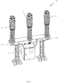
- FIG 1 is a diagrammatic perspective representation of an exemplary circuit breaker 100, in accordance with one or more embodiments of the present disclosure.
- the depicted circuit breaker 100 is a three-pole pillar mounted circuit breaker; however, for the purposes of the present disclosure, the circuit breaker 100 may be any type of high-voltage circuit breaker as known in the art.
- the circuit breaker 100 includes a common breaker base 102 to which the various components are mounted. In the present three-pole circuit breaker 100, there pole columns 104, 106 and 108 are provided which are mounted on the common breaker base 102.
- the pole columns 104, 106 and 108 are connected by tubes to a gas compartment and are filled with insulating gas, such as, but not limited to, SF6 (Sulphur Hexafluoride) for arc-quenching and insulating purposes.
- insulating gas such as, but not limited to, SF6 (Sulphur Hexafluoride) for arc-quenching and insulating purposes.
- the gas density is monitored by a density monitor (not shown), and the pressure can be displayed by a pressure gauge or a pressure display on the density monitor.
- the circuit breaker 100 also includes an operating mechanism unit 110 fastened to the breaker base 102.
- a mounting plate (not shown) is integrated in the operating mechanism unit 110, which contains all equipment for control and monitoring of the circuit breaker 100 and also terminal blocks required for electrical connections.
- the circuit breaker 100 further includes a spring drive mechanism (not shown) located in the operating mechanism unit 110.
- the spring drive mechanism includes closing and opening springs, and the energy required for switching is stored in one closing spring common to all three poles and one opening spring.
- the pole column 106 is actuated by the spring drive mechanism via a corner gear 112 (as shown in FIG. 2 ) and is connected with corner gears of the pole columns 104 and 108 by means of coupling rods.
- the circuit breaker 100 further includes a switching position indicator 114 which indicates the position and status of all switch equipment thereof.
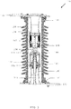
- FIG 2 is a diagrammatic cross-sectional representation of the pole column 104 of the circuit breaker 100. It may be appreciated that all of the three pole columns 104, 106 and 108 are similar in design and the present illustration can be construed to be representative of any of the three pole columns 104, 106 and 108 for the purposes of the present disclosure.
- the pole column 104 includes a post insulator 116 which provides insulation against earth. Further, the pole column 104 includes an insulated drive rod 118.
- the pole column 104 includes an interrupter unit 120 mounted on the post insulator 116.
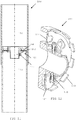
- FIG 3 is a diagrammatic cross-sectional representation of the interrupter unit 120.
- the interrupter unit 120 contains the filter material 122, generally in the form of filter bag.
- the filter material 122 is used for the absorption of decomposition products of the insulating gas (like SF6) and for keeping the gas dry.
- the interrupter unit 120 further includes a gas-tight jacket 124 which accommodates the breaker contacts. In the pole column 104, the switching motion is transferred from the spring drive mechanism (at earth potential) via a coupling rod 126, a shaft 128, and thereby from the insulated drive rod 118 to the interrupter unit 120 (at high voltage potential).
- the main circuit for the interrupter unit 120 includes an upper high-voltage terminal 130, a lower high-voltage terminal 132, a diffuser socket 134, ring-placed contact laminations 136 arranged with the diffuser socket 134, a heat cylinder 138 and an operating socket 140.
- the contact laminations 136 are self-sprung and centrically pressed inwards, which ensures the necessary contact pressure on the heat cylinder 138 and the diffuser socket 134.Also, the upper high-voltage terminal 130 and the lower high-voltage terminal 132 are mounted using O-rings 141.
- an arcing circuit is arranged parallel to the main circuit, which is made up of a pin 142 (also referred to as first electrical contact 142) situated in the diffuser socket 134 and a moving tube contact 144 (also referred to as second electrical contact 144) placed in the heat cylinder 138.
- the pin 142 and the tube contact 144 are made of materials, which produce only minimal contact erosion.
- a piston 146 and a pull rod 148 are arranged in the interrupter unit 120.
- the tube contact 144, the piston 146 and the heat cylinder 138 are mechanically interconnected and coupled with the pull rod 148, and form the moving parts of the interrupter unit 120.
- a valve assembly 150 is arranged in cylindrical casting 152, which together with an arc quenching nozzle 154 makes up the compression unit for arc quenching purposes.
- FIGS 4A and 4B are partial schematic representations of an arc pressure control arrangement 155, implemented in the circuit breaker 100, or specifically the interrupter unit 120 of the circuit breaker 100, depicting stages of arc quenching operation therein.
- the arc pressure control arrangement 155 includes the first electrical contact 142 and the second electrical contact 144.
- the first electrical contact 142 and the second electrical contact 144 are configured to generate an electrical arc upon being separated during operation of the circuit breaker 100.
- the arc pressure control arrangement 155 includes a first chamber (generally represented by numeral 156) at least partially surrounding the first electric contact 142 and the second electric contact 144.
- the arc pressure control arrangement 155 includes a second chamber (generally represented by numeral 158) disposed adjacent to the first chamber 156.
- the second chamber 158 is filled with insulating gas, such as, for example, SF6.
- the first chamber 156 is a compression volume and the second chamber 158 is a low-pressure volume in the circuit breaker 100, and the said terms have been interchangeably used in the description without any limitations.
- the valve assembly 150 interconnects the first chamber 156 and the second chamber 158. The valve assembly 150 regulates the flow of the insulating gas from the second chamber 158 into the first chamber 156, and vice-versa.
- valve assembly 150 allows the flow of the insulating gas based on desired threshold pressure of the insulating gas in the first chamber 156.
- valve assembly 150 is configured to allow threshold-based flow of the insulating gas into and out of the first chamber 156.
- the first chamber 156 includes an internal storage volume that is greater than about 500 mm 3 .
- an internal storage volume of the first chamber 156 may be greater than about 1,000 mm 3 for a 600V/250A circuit breaker, or even greater than about 1,500 mm 3 for a 600V/250A circuit breaker.
- the internal storage volume of the second chamber 158 may be about 2,000 mm 3 or more.
- the second chamber 158 may be a rectangular shape and may include an internal height of about 38 mm, an internal width of about 6 mm, and an internal thickness of 6 mm. Other sizes, shapes, and storage volumes for the second chamber 158 may be used.
- the main contact that exists between the contact laminations 136 and the heat cylinder 138 is opened ( FIG 4A ).
- the arcing contact consisting of the first electrical contact 142 and the second electrical contact 144 remains closed, with the result that the current commutates onto the arcing contact.
- the arcing contact opens creating an arc.
- the heat cylinder 138 moves downward and compresses the quenching gas between the heat cylinder 138 and plate supporting the valve assembly 150.
- FIGS 5-10 are different diagrammatic representations of the valve assembly 150.
- the valve assembly 150 includes a valve body 160.
- the valve body 160 has a substantially cylindrical or annular shape.
- the valve body 160 has a radially inner, central opening 161.
- the valve body 160 is guided through the wall of the first chamber 156, with a gas passage which connects the first chamber 156 and the second chamber 158.
- a radially outer surface of the valve body 160 may contact a surrounding surface (not shown) of the circuit breaker 100 in a sealing (substantially gas-tight) manner.
- a radially inner surface of the valve body 160 may contact a radially outer surface of the drive rod 118 (as may be seen from FIG 2 ) or an extension of the drive rod 118 protruding through the central opening 161 of the valve body 160 in a sealing manner.
- suitable sealing may be provided such as sealing rings and the like.
- the valve assembly 150 further includes a first valve plate 162 movably mounted in the valve body 160.
- the valve assembly 150 also includes a second valve plate 164 movably seated on the first valve plate 162.
- the second valve plate 164 is arranged in the valve body 162 so as to move between a first position and a second position, wherein in the first position, the second valve plate 164 lifts above the first valve plate 162 and in the second position, the second valve plate 164 seats upon the first valve plate 162.
- the valve body 160, along with the first valve plate 162 and the second valve plate 164 may be formed of any suitable metallic material, such as, but not limited to, stainless steel or the like.
- valve body 160 has generally larger diameter than the first valve plate 162 and the second valve plate 164, while the first valve plate 162 and the second valve plate 164 have substantially similar diameter.
- first valve plate 162 and the second valve plate 164 may be pressed to the valve body 160 in a sealing manner.
- the first valve plate 162 may include seats defined therein onto which the second valve plate 164 is seated. As can best be seen from FIGS 9-10 , the first valve plate 162 has one or more openings 166 formed therein, presently seven openings 166. The openings 166 are radially segregated on planar exposed surface of the first valve plate 162. Further, the second valve plate 164 is a substantially solid annular member seated on the first valve plate 162 in a manner so as to seal the one or more openings 166 thereof. Further, as may be seen, the valve body 160 has one or more openings 168, presently five openings 168.
- the openings 168 are radially segregated on planar exposed surface of the valve body 160.
- the openings 168 are generally disposed in-line with the openings 166 in the first valve plate 162, enabling a fluid flow through the first valve plate 162, for example in a basically axial direction of the circuit breaker 100.
- a stop (not shown) may be integrated into the valve body 160 and limits the movement of the first valve plate 162 when the circuit breaker 100 closes.
- the valve assembly 150 further includes a torsion spring 170 arranged in the valve body 160.
- the torsion spring 170 is coupled to the first valve plate 162.
- the torsion spring 170 is mounted in the valve body 160 by means of fasteners 172, optionally supported by spacers 174 or the like.
- the torsion spring 170 implemented with the valve body 160 is a double torsion spring, as known in the art; however, it may be appreciated that single torsion spring or any other type of torsion spring, or still any other type of spring with similar configuration may be implemented as the torsion spring 170 without departing from the scope and the spirit of the present disclosure.
- the torsion spring 170 is configured to constrain the movement of the first valve plate 162 in the valve body 160, as will be discussed in more detail in the proceeding paragraphs.
- FIGS 11-16 are representations depicting various positions of the valve assembly 150 during arc quenching operation in the circuit breaker 100.
- the first valve plate 162 is arranged in the valve body 160 with the second valve plate 164 in the second position thereof, i.e. seated on the first valve plate 162.
- the valve assembly 150 is moved to gas upward state.
- the second valve plate 164 assumes first position during filling of the insulating gas into the second chamber 158 thereby, allowing passage to the insulated gas into the first chamber 156 which is at a lower pressure than the second chamber 158.
- the second valve plate 164 assumes second position upon completion of the filling of the insulating gas when the pressure in the first chamber 156 is higher than in the second chamber 158. In other words, the second valve plate 164 gets lifted from the first valve plate 162 due to pressure of the insulating gas in the second chamber 158 to provide a flow path for the insulating gas to flow from the second chamber 158 into the first chamber 156.
- an arc is formed in the first chamber 156 of the circuit breaker 100.
- the arc extending between the first electrical contact 142 and the second electrical contact 144 (e.g., stationary and moveable electrical contacts), produces arcing gases and also heats up and pressurizes the insulating gas within the first chamber 156. This causes a flow of the heated insulating gas and arc gasses, due to the pressure change, into the second chamber 158 disposed adjacent to the first chamber 156, but only at certain times during the arcing event.
- the valve assembly 150 upon generation of the electrical arc, the valve assembly 150 is moved to gas downward state.
- the second valve plate 164 assumes first position upon generation of the electrical arc by overcoming constrain of the torsion spring 170 due to additional pressure built in the first chamber 156.
- the first valve plate 162 is separated from the second valve plate 164 due to further pressure build-up of the insulating gas in the first chamber 156 overcoming the constrain of the torsion spring 170 coupled thereto to provide a flow path for the insulating gas to flow out of the first chamber 156 to the second chamber 158.
- This gas flow may cool down the first chamber 156 and may also increase dielectric strength thereof.
- the gas flow around the arc increases the arc voltage, thereby providing better current limiting performance.
- the torsion spring 170 is tensioned to define the constrain on the movement of the first valve plate 162 in the valve body 160 based on desired threshold pressure of the insulating gas in the first chamber 156. It may be appreciated by a person skilled in the art that the constrain may be defined based on the voltage rating of the circuit breaker 100, in order to be able to quench the generated arc in required time to avoid any damage.
- the torsion spring 170 is arranged at an angle of disposition (A) (as shown in FIG. 8 ) with respect to the first valve plate 162 in the valve body 160. This enables to vary the constrain on the movement of the first valve plate 162 in the valve body 160, which in turn could be used to regulate the movement of the first valve plate 162 in the valve body 160 based on desired threshold pressure of the insulating gas in the first chamber 156.
- the torsion spring 170 is arranged proximal to a central opening 161 in the valve body 160. In another embodiment, the torsion spring 170 is arranged proximal to an outer wall 165 of the valve body 160. That is, the torsion spring 170 may be arranged either on a side in the valve body 160 or around the central opening 162 thereof, thus reducing any possible hindrance to the flow path of insulating gas into and out of the first chamber 156.
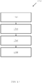
- FIG 17 is a flowchart 1700 listing steps involved in a method of operating a circuit breaker, such as the circuit breaker 100.
- the method includes separating a first electrical contact (such as, the first electrical contact 142) from a second electrical contact (such as, the second electrical contact 144) in a first chamber (such as, the first chamber 156) of the circuit breaker 100 to generate an electrical arc.
- the method includes filling a second chamber (such as, the second chamber 158), disposed adjacent to the first chamber 156 in the circuit breaker 100, with insulating gas (such as, SF6).
- insulating gas such as, SF6
- the method includes providing a valve assembly (such as, the valve assembly 150) with a first valve plate (such as, the first valve plate 162) and a second valve plate (such as, the second valve plate 164) movably seated on the first valve plate 162 such that during filling operation, the second valve plate 164 gets lifted from the first valve plate 162 due to pressure of the insulating gas in the second chamber 158 to provide a flow path for the insulating gas to flow from the second chamber 158 into the first chamber 156, and subsequently the second valve plate 164 gets seated back onto the first valve plate 162 due to the pressure build-up of the insulating gas in the first chamber 156.
- a valve assembly such as, the valve assembly 150
- a first valve plate such as, the first valve plate 162
- a second valve plate such as, the second valve plate 164
- the method includes providing a torsion spring (such as, the torsion spring 170) configured to constrain the movement of the first valve plate 162 such that upon generation of the electrical arc, the first valve plate 162 is separated from the second valve plate 164 due to further pressure build-up of the insulating gas in the first chamber 156 overcoming the constrain of the torsion spring 170 coupled thereto to provide a flow path for the insulating gas to flow out of the first chamber 156 to the second chamber 158.
- a torsion spring such as, the torsion spring 170
- the function of multiple linear helical springs as used with valve arrangements of prior-art is carried out by utilizing a single torsion spring 170 below the first valve plate 162 (i.e. the pressure plate) .
- Use of the torsion spring 170 results in compactness of the valve assembly 150, as only one torsion spring is sufficient for executing the operation of the valve assembly 150.
- no guides are required to operate the torsional spring 170.
- the valve body 160 itself act as guide for the first valve plate 162 and the second valve plate 164.
- valve assembly 150 incorporates less number of components, and thus provides an economical and cost-effective proposition to manufacture. This further results in more opening or space for the flow of the insulating gas, for flow into and out of the first chamber 156, thus increasing in efficiency and response time for the circuit breaker 100.
Landscapes
- Circuit Breakers (AREA)
Abstract
Description
- The present invention relates generally to arc chambers for extinguishing arcs, such as in circuit breakers, and more particularly relates to a valve assembly for regulating flow of insulating gas in a circuit breaker.
- In general, a circuit breaker operates to engage and disengage a selected electrical circuit from an electrical power supply. The circuit breaker ensures current interruption thereby providing protection to the electrical circuit from continuous over current conditions and high current transients due to, for example, electrical short circuits. Such circuit breakers operate by separating a pair of internal electrical contacts contained within a housing (e.g., molded case) of the circuit breaker. Typically, one electrical contact is stationary while the other is movable (e.g., typically mounted on a pivotable contact arm).
- The contact separation may occur manually, such as when a person throws an operating handle of the circuit breaker. This may engage an operating mechanism, which may be coupled to the contact arm and moveable electrical contact. Otherwise, the electrical contacts may be separated automatically when an over current, short circuit, or fault condition is encountered. Automatic tripping may be accomplished by an operating mechanism actuated via a thermal overload element (e.g., a bimetal element) or by a magnetic element, or even by an actuator (e.g., a solenoid).
- Upon separation of the electrical contacts by tripping, an intense electrical arc may be formed in an arc chamber containing the electrical contacts. This separation may occur due to heat and/or high current through the circuit breaker or due to sensing a ground or other arc fault. It is desirable to extinguish the arc as quickly as possible to avoid damaging internal components of the circuit breaker.
- In power distribution networks, a circuit breaker of type, called a gas-insulated circuit breaker is commonly used. Such gas-insulated circuit breaker is designed in such a way that in the event of a separating of the contacts, or in the case of a short circuit, the arc is blasted with gas and consequently quenched as quickly as possible. The gas which is used most for this purpose is SF6 (Sulphur Hexafluoride).
- In the case of such circuit breaker, a pressure chamber, in which the arc is created, is connected in a valve-controlled manner to a compression chamber. The compression chamber is connected to a low-pressure chamber via a valve arrangement. The valve arrangement, on the low-pressure chamber side, is pressed by a spring against a valve holder in the direction of the compression volume. Gas can therefore flow from the compression volume into the low-pressure chamber only when its pressure is higher than the spring force.
- In a high voltage circuit breaker, a valve is typically implemented to regulate the flow of gas towards arcing contact. Such a valve allows the free flow of gas in one direction while gas flow in other direction is depending on the pressure built in compression volume. It is required that the valve should allow gas flow towards arcing contacts during gas filling. Further, during opening of the circuit breaker, the valve has to be closed such that pressure in the compression volume increases up to specified limit. Also, it is required that once the pressure in compression volume increases beyond specified limit, valve should open.
- European Patent Application Number
3419039A1 ('039 application) relates to an electric high-voltage circuit breaker comprising a primary chamber and a compression chamber, wherein said circuit breaker further comprises a valve configured to control a fluid flow between said primary chamber and said compression chamber. The electric high-voltage circuit breaker of the '039 application discloses that said valve comprises a valve body, a first valve plate that is arranged axially movable with respect to said valve body, and a second valve plate that is arranged between and movable, preferably at least axially movable, with respect to said valve body and said first valve plate, wherein said first valve plate comprises at least one opening enabling a fluid flow through said first valve plate, wherein a first surface of said valve body forms a valve seat for said first valve plate, and wherein a first surface of said first valve plate forms a valve seat for said second valve plate. - In the circuit breaker of the '039 application, one or more guide pins may be provided for guiding an axial movement of both said first valve plate and said second valve plate. Further, a first spring force mechanism is provided to press said first valve plate to said valve seat of the valve body, and a second spring force mechanism is provided to press said second valve plate to said valve seat of the first valve plate. Each of the spring force mechanisms may comprise one or more springs (for example, helical springs) arranged at said guide pins.
- The type of construction implemented for the valve in the circuit breaker, as disclosed in the '039 application, is relatively complicated and requires a large number of components. The use of that many number of components may result in hindrance to the path of flow of gas which is undesirable. It may be appreciated that pressure opening from compression volume is only possible from one side in such configuration. Further, in such configuration of the valve arrangement, typically, a pneumatic press is required to mount the spring on the valve which is an added expense. Also, the load value needs to be set for each of the springs to get desired pressure release output, which may be time-consuming and cumbersome.
- In light of the above, there is a need of a circuit breaker with a valve assembly to regulate the flow of gas towards arcing contact, which is simple in construction, is economical to manufacture and is efficient to operate.
- The object of the present disclosure is achieved by a circuit breaker comprising first and second electrical contacts, the electrical contacts configured to generate an electrical arc upon being separated during operation of the circuit breaker. The circuit breaker comprises a first chamber at least partially surrounding the first and second electric contacts, and a second chamber filled with insulating gas. The circuit breaker further comprises a valve assembly interconnecting the first chamber and the second chamber. The valve assembly is configured to allow threshold-based flow of the insulating gas into and out of the first chamber. The valve assembly comprises a valve body. The valve assembly also comprises a first valve plate movably mounted in the valve body and a second valve plate arranged in the valve body so as to move between a first position and a second position, wherein in the first position, the second valve plate lifts above the first valve plate and in the second position, the second valve plate seats upon the first valve plate. The valve assembly further comprises a torsion spring arranged in the valve body and coupled to the first valve plate. The torsion spring is configured to constrain the movement of the first valve plate in the valve body.
- In an embodiment, the second valve plate assumes first position during filling of the insulating gas into the second chamber thereby, allowing passage to the insulated gas into the first chamber which is at a lower pressure than the second chamber, and wherein the second valve plate assumes second position upon completion of the filling of the insulating gas when the pressure in the first chamber is higher than in the second chamber.
- In an embodiment, the second valve plate assumes first position upon generation of the electrical arc by overcoming constrain of the torsion spring due to additional pressure built in the first chamber.
- In an embodiment, the torsion spring is tensioned to define the constrain on the movement of the first valve plate in the valve body based on desired threshold pressure of the insulating gas in the first chamber.
- In an embodiment, the torsion spring is arranged at an angle of disposition with respect to the first valve plate in the valve body to define the constrain on the movement of the first valve plate in the valve body.
- In an embodiment, the torsion spring is arranged proximal to a central opening in the valve body.
- In an embodiment, the torsion spring is arranged proximal to an outer wall of the valve body.
- In an embodiment, the valve body has a substantially cylindrical shape.
- In an embodiment, the first valve plate has one or more openings formed therein, and wherein the second valve plate is seated on the first valve plate in a manner so as to seal the one or more openings thereof.
- The object of the present disclosure is also achieved by a valve assembly for a circuit breaker having a first chamber and a second chamber filled with insulating gas, the valve assembly being of the configuration as discussed in preceding paragraph.
- The object of the present disclosure is further achieved by an arc pressure control arrangement, which may be implemented, for example, in a circuit breaker. Herein, the arc pressure control arrangement comprises a first chamber containing first and second electrical contacts, the electrical contacts configured to generate an electrical arc upon being separated during operation of the circuit breaker. The arc pressure control arrangement further comprises a second chamber filled with insulating gas. The arc pressure control arrangement further comprises a valve assembly interconnecting the first chamber and the second chamber, the valve assembly being of the configuration as discussed in preceding paragraphs.
- The object of the present disclosure is further achieved by a method of operating a circuit breaker. The method comprises separating a first electrical contact from a second electrical contact in a first chamber of the circuit breaker to generate an electrical arc. The method further comprises filling a second chamber, disposed adjacent to the first chamber in the circuit breaker, with insulating gas. The method further comprises providing a valve assembly with a first valve plate and a second valve plate movably seated on the first valve plate such that during filling operation, the second valve plate gets lifted from the first valve plate due to pressure of the insulating gas in the second chamber to provide a flow path for the insulating gas to flow from the second chamber into the first chamber, and subsequently the second valve plate gets seated back onto the first valve plate due to the pressure build-up of the insulating gas in the first chamber. The method further comprises providing a torsion spring configured to constrain the movement of the first valve plate such that upon generation of the electrical arc, the first valve plate is separated from the second valve plate due to further pressure build-up of the insulating gas in the first chamber overcoming the constrain of the torsion spring coupled thereto to provide a flow path for the insulating gas to flow out of the first chamber to the second chamber.
- Still other aspects, features, and advantages of the invention are readily apparent from the following detailed description, simply by illustrating a number of particular embodiments and implementations, including the best mode contemplated for carrying out the invention. The invention is also capable of other and different embodiments, and its several details can be modified in various obvious respects, all without departing from the scope of the invention. Accordingly, the drawings and description are to be regarded as illustrative in nature, and not as restrictive.
- A more complete appreciation of the present disclosure and many of the attendant aspects thereof will be readily obtained as the same becomes better understood by reference to the following description when considered in connection with the accompanying drawings:
- FIG 1
- is a diagrammatic perspective representation of an exemplary circuit breaker, in accordance with an embodiment of the present invention;
- FIG 2
- is a diagrammatic cross-sectional representation of a pole column of the circuit breaker as shown in
FIG 1 , in accordance with an embodiment of the present invention; - FIG 3
- is a diagrammatic cross-sectional representation of an interrupter unit of the circuit breaker, in accordance with an embodiment of the present invention;
- FIGS 4A-4B
- are partial schematic representations of an arc
pressure control arrangement 155 depicting arc quenching operation therein, in accordance with an embodiment of the present invention; - FIG 5
- is a diagrammatic right-side perspective representation of a valve assembly, in accordance with an embodiment of the present invention;
- FIG 6
- is a diagrammatic left-side perspective representation of the valve assembly, in accordance with an embodiment of the present invention;
- FIG 7
- is a diagrammatic side representation of the valve assembly, in accordance with an embodiment of the present invention;
- FIG 8
- is a diagrammatic cross-sectional representation of the valve assembly, in accordance with an embodiment of the present invention;
- FIG 9
- is a diagrammatic right-side exploded representation of the valve assembly, in accordance with an embodiment of the present invention;
- FIG 10
- is a diagrammatic left-side exploded representation of the valve assembly, in accordance with an embodiment of the present invention;
- FIG 11
- is a schematic representation of the circuit breaker with the valve assembly in normal state, in accordance with an embodiment of the present invention;
- FIG 12
- is a diagrammatic cross-sectional representation of the valve assembly in normal state thereof, in accordance with an embodiment of the present invention;
- FIG 13
- is a schematic representation of the circuit breaker with the valve assembly in gas upward state, in accordance with an embodiment of the present invention;
- FIG 14
- is a diagrammatic cross-sectional representation of the valve assembly in gas upward state thereof, in accordance with an embodiment of the present invention;
- FIG 15
- is a schematic representation of the circuit breaker with the valve assembly in gas downward state, in accordance with an embodiment of the present invention;
- FIG 16
- is a diagrammatic cross-sectional representation of the valve assembly in gas downward state thereof, in accordance with an embodiment of the present invention;
- FIG 17
- is a flowchart listing steps involved in a method of operating a circuit breaker, in accordance with an embodiment of the present invention.
- Various embodiments are described with reference to the drawings, wherein like reference numerals are used to refer the drawings, wherein like reference numerals are used to refer to like elements throughout. In the following description, for the purpose of explanation, numerous specific details are set forth in order to provide thorough understanding of one or more embodiments. It may be evident that such embodiments may be practiced without these specific details.
- In the following description, for the purposes of explanation, numerous specific details are set forth in order to provide a thorough understanding of the embodiments of the invention. It is apparent, however, to one skilled in the art that the embodiments of the invention may be practiced without these specific details or with an equivalent arrangement. In other instances, well-known structures and devices are shown in block diagram form in order to avoid unnecessarily obscuring the embodiments of the invention.
- Example embodiments of an arc pressure control arrangement described herein may be included in a circuit breaker to prevent a re-ignition failure of the circuit breaker. In certain example embodiments, upon contact separation, an arc is formed in a compression volume of the circuit breaker. The arc, extending between the first and second electrical contacts (e.g., stationary and moveable electrical contacts), produces arcing gases and also heats up and pressurizes the insulating gas within the compression volume. This causes a flow of the heated insulating gas and arc gasses, due to the pressure change, into a low-pressure volume disposed adjacent to the compression volume, but only at certain times during the arcing event.
- A valve assembly is provided between the compression volume and the low-pressure volume to allow flow into and out of the compression volume only at the certain times during the arcing event. For example, the valve assembly may allow gas flow only when an inlet threshold pressure in the compression volume is exceeded. Further, the valve assembly may allow gas flow only when a pressure in the compression volume falls below an outlet threshold pressure. Thus, gas flows into the low-pressure volume after the gas pressure in the compression volume reaches the inlet threshold pressure, is held in the low-pressure volume for part of the arc cycle, and then flows out of the low-pressure volume and back into the compression volume when the pressure in the compression volume falls below the outlet threshold pressure.
- Examples of a circuit breaker, a valve assembly for a circuit breaker, an arc pressure control arrangement, and a method of operating a circuit breaker are disclosed and fully described with reference to
FIGS 1 through 17 herein. -
FIG 1 is a diagrammatic perspective representation of anexemplary circuit breaker 100, in accordance with one or more embodiments of the present disclosure. In the present illustration, the depictedcircuit breaker 100 is a three-pole pillar mounted circuit breaker; however, for the purposes of the present disclosure, thecircuit breaker 100 may be any type of high-voltage circuit breaker as known in the art. Thecircuit breaker 100 includes acommon breaker base 102 to which the various components are mounted. In the present three-pole circuit breaker 100, therepole columns common breaker base 102. Thepole columns - The
circuit breaker 100 also includes anoperating mechanism unit 110 fastened to thebreaker base 102. A mounting plate (not shown) is integrated in theoperating mechanism unit 110, which contains all equipment for control and monitoring of thecircuit breaker 100 and also terminal blocks required for electrical connections. Thecircuit breaker 100 further includes a spring drive mechanism (not shown) located in theoperating mechanism unit 110. Typically, the spring drive mechanism includes closing and opening springs, and the energy required for switching is stored in one closing spring common to all three poles and one opening spring. In thecircuit breaker 100, thepole column 106 is actuated by the spring drive mechanism via a corner gear 112 (as shown inFIG. 2 ) and is connected with corner gears of thepole columns circuit breaker 100 further includes aswitching position indicator 114 which indicates the position and status of all switch equipment thereof. -
FIG 2 is a diagrammatic cross-sectional representation of thepole column 104 of thecircuit breaker 100. It may be appreciated that all of the threepole columns pole columns pole column 104 includes apost insulator 116 which provides insulation against earth. Further, thepole column 104 includes aninsulated drive rod 118. Thepole column 104 includes aninterrupter unit 120 mounted on thepost insulator 116.FIG 3 is a diagrammatic cross-sectional representation of theinterrupter unit 120. Referring toFIGS 2 and3 in combination, theinterrupter unit 120 contains thefilter material 122, generally in the form of filter bag. Thefilter material 122 is used for the absorption of decomposition products of the insulating gas (like SF6) and for keeping the gas dry. Theinterrupter unit 120 further includes a gas-tight jacket 124 which accommodates the breaker contacts. In thepole column 104, the switching motion is transferred from the spring drive mechanism (at earth potential) via acoupling rod 126, ashaft 128, and thereby from theinsulated drive rod 118 to the interrupter unit 120 (at high voltage potential). - As illustrated, the main circuit for the
interrupter unit 120 includes an upper high-voltage terminal 130, a lower high-voltage terminal 132, adiffuser socket 134, ring-placedcontact laminations 136 arranged with thediffuser socket 134, aheat cylinder 138 and anoperating socket 140. Herein, thecontact laminations 136 are self-sprung and centrically pressed inwards, which ensures the necessary contact pressure on theheat cylinder 138 and the diffuser socket 134.Also, the upper high-voltage terminal 130 and the lower high-voltage terminal 132 are mounted using O-rings 141. Further, an arcing circuit is arranged parallel to the main circuit, which is made up of a pin 142 (also referred to as first electrical contact 142) situated in thediffuser socket 134 and a moving tube contact 144 (also referred to as second electrical contact 144) placed in theheat cylinder 138. Herein, thepin 142 and thetube contact 144 are made of materials, which produce only minimal contact erosion. Further, as illustrated, apiston 146 and apull rod 148 are arranged in theinterrupter unit 120. Herein, thetube contact 144, thepiston 146 and theheat cylinder 138 are mechanically interconnected and coupled with thepull rod 148, and form the moving parts of theinterrupter unit 120. In thecircuit breaker 100, avalve assembly 150 is arranged incylindrical casting 152, which together with anarc quenching nozzle 154 makes up the compression unit for arc quenching purposes. -
FIGS 4A and 4B are partial schematic representations of an arcpressure control arrangement 155, implemented in thecircuit breaker 100, or specifically theinterrupter unit 120 of thecircuit breaker 100, depicting stages of arc quenching operation therein. As illustrated, the arcpressure control arrangement 155 includes the firstelectrical contact 142 and the secondelectrical contact 144. Herein, the firstelectrical contact 142 and the secondelectrical contact 144 are configured to generate an electrical arc upon being separated during operation of thecircuit breaker 100. As illustrated, the arcpressure control arrangement 155 includes a first chamber (generally represented by numeral 156) at least partially surrounding the firstelectric contact 142 and the secondelectric contact 144. Further, the arcpressure control arrangement 155 includes a second chamber (generally represented by numeral 158) disposed adjacent to thefirst chamber 156. Herein, thesecond chamber 158 is filled with insulating gas, such as, for example, SF6. It may be understood that thefirst chamber 156 is a compression volume and thesecond chamber 158 is a low-pressure volume in thecircuit breaker 100, and the said terms have been interchangeably used in the description without any limitations. In the arcpressure control arrangement 155, as illustrated, thevalve assembly 150 interconnects thefirst chamber 156 and thesecond chamber 158. Thevalve assembly 150 regulates the flow of the insulating gas from thesecond chamber 158 into thefirst chamber 156, and vice-versa. In particular, thevalve assembly 150 allows the flow of the insulating gas based on desired threshold pressure of the insulating gas in thefirst chamber 156. Thereby, thevalve assembly 150 is configured to allow threshold-based flow of the insulating gas into and out of thefirst chamber 156. - In one or more embodiments, the
first chamber 156 includes an internal storage volume that is greater than about 500 mm3. For example, an internal storage volume of the first chamber 156may be greater than about 1,000 mm3 for a 600V/250A circuit breaker, or even greater than about 1,500 mm3 for a 600V/250A circuit breaker. In some embodiments, the internal storage volume of thesecond chamber 158 may be about 2,000 mm3 or more. In some example embodiments, thesecond chamber 158 may be a rectangular shape and may include an internal height of about 38 mm, an internal width of about 6 mm, and an internal thickness of 6 mm. Other sizes, shapes, and storage volumes for thesecond chamber 158 may be used. - In an opening operation, the main contact that exists between the
contact laminations 136 and theheat cylinder 138 is opened (FIG 4A ). The arcing contact, consisting of the firstelectrical contact 142 and the secondelectrical contact 144 remains closed, with the result that the current commutates onto the arcing contact. During the continued course of the opening operation, the arcing contact opens creating an arc. At the same time, theheat cylinder 138 moves downward and compresses the quenching gas between theheat cylinder 138 and plate supporting thevalve assembly 150. This causes the quenching gas to be forced in the direction opposite to the movement of the moving contact components, into theheat cylinder 138 and through the gap between the secondelectrical contact 144 and the arc-quenching nozzle, thus quenching the arc. With large short-circuit currents, the quenching gas surrounding the firstelectrical contact 142 in the arcing chamber is heated by the arc's energy and driven into theheat cylinder 138 at high pressure. When the current passes through zero, the gas flows back from theheat cylinder 138 into the nozzle and quenches the arc. -
FIGS 5-10 are different diagrammatic representations of thevalve assembly 150. As illustrated, thevalve assembly 150 includes avalve body 160. Herein, thevalve body 160 has a substantially cylindrical or annular shape. As shown, thevalve body 160 has a radially inner,central opening 161. Thevalve body 160 is guided through the wall of thefirst chamber 156, with a gas passage which connects thefirst chamber 156 and thesecond chamber 158. - Generally, a radially outer surface of the
valve body 160 may contact a surrounding surface (not shown) of thecircuit breaker 100 in a sealing (substantially gas-tight) manner. Similarly, a radially inner surface of thevalve body 160 may contact a radially outer surface of the drive rod 118 (as may be seen fromFIG 2 ) or an extension of thedrive rod 118 protruding through thecentral opening 161 of thevalve body 160 in a sealing manner. As an example, at both radially outer surface and radially inner surface, suitable sealing may be provided such as sealing rings and the like. - The
valve assembly 150 further includes afirst valve plate 162 movably mounted in thevalve body 160. Thevalve assembly 150 also includes asecond valve plate 164 movably seated on thefirst valve plate 162. Herein, thesecond valve plate 164 is arranged in thevalve body 162 so as to move between a first position and a second position, wherein in the first position, thesecond valve plate 164 lifts above thefirst valve plate 162 and in the second position, thesecond valve plate 164 seats upon thefirst valve plate 162. In the present examples, thevalve body 160, along with thefirst valve plate 162 and thesecond valve plate 164, may be formed of any suitable metallic material, such as, but not limited to, stainless steel or the like. Herein, thevalve body 160 has generally larger diameter than thefirst valve plate 162 and thesecond valve plate 164, while thefirst valve plate 162 and thesecond valve plate 164 have substantially similar diameter. Generally, thefirst valve plate 162 and thesecond valve plate 164 may be pressed to thevalve body 160 in a sealing manner. - In one or more examples, the
first valve plate 162 may include seats defined therein onto which thesecond valve plate 164 is seated. As can best be seen fromFIGS 9-10 , thefirst valve plate 162 has one ormore openings 166 formed therein, presently sevenopenings 166. Theopenings 166 are radially segregated on planar exposed surface of thefirst valve plate 162. Further, thesecond valve plate 164 is a substantially solid annular member seated on thefirst valve plate 162 in a manner so as to seal the one ormore openings 166 thereof. Further, as may be seen, thevalve body 160 has one ormore openings 168, presently fiveopenings 168. Similar to theopenings 166, theopenings 168 are radially segregated on planar exposed surface of thevalve body 160. Herein, theopenings 168 are generally disposed in-line with theopenings 166 in thefirst valve plate 162, enabling a fluid flow through thefirst valve plate 162, for example in a basically axial direction of thecircuit breaker 100. In some examples, a stop (not shown) may be integrated into thevalve body 160 and limits the movement of thefirst valve plate 162 when thecircuit breaker 100 closes. - The
valve assembly 150 further includes atorsion spring 170 arranged in thevalve body 160. In the present configuration, thetorsion spring 170 is coupled to thefirst valve plate 162. As can best be seen fromFIGS 9-10 , thetorsion spring 170 is mounted in thevalve body 160 by means offasteners 172, optionally supported byspacers 174 or the like. Such assembly may be contemplated by a person skilled in the art in light of the included drawings and thus has not been explained herein for the brevity of the present disclosure.In the present embodiments, thetorsion spring 170 implemented with thevalve body 160 is a double torsion spring, as known in the art; however, it may be appreciated that single torsion spring or any other type of torsion spring, or still any other type of spring with similar configuration may be implemented as thetorsion spring 170 without departing from the scope and the spirit of the present disclosure. Herein, thetorsion spring 170 is configured to constrain the movement of thefirst valve plate 162 in thevalve body 160, as will be discussed in more detail in the proceeding paragraphs. -
FIGS 11-16 are representations depicting various positions of thevalve assembly 150 during arc quenching operation in thecircuit breaker 100. As illustrated inFIGS 11-12 , during normal state of thevalve assembly 150, thefirst valve plate 162 is arranged in thevalve body 160 with thesecond valve plate 164 in the second position thereof, i.e. seated on thefirst valve plate 162. Further, as illustrated inFIGS 13-14 , during filling operation, thevalve assembly 150 is moved to gas upward state. Herein, thesecond valve plate 164 assumes first position during filling of the insulating gas into thesecond chamber 158 thereby, allowing passage to the insulated gas into thefirst chamber 156 which is at a lower pressure than thesecond chamber 158. Further, thesecond valve plate 164 assumes second position upon completion of the filling of the insulating gas when the pressure in thefirst chamber 156 is higher than in thesecond chamber 158. In other words, thesecond valve plate 164 gets lifted from thefirst valve plate 162 due to pressure of the insulating gas in thesecond chamber 158 to provide a flow path for the insulating gas to flow from thesecond chamber 158 into thefirst chamber 156. - As discussed, upon contact separation, an arc is formed in the
first chamber 156 of thecircuit breaker 100. The arc, extending between the firstelectrical contact 142 and the second electrical contact 144 (e.g., stationary and moveable electrical contacts), produces arcing gases and also heats up and pressurizes the insulating gas within thefirst chamber 156. This causes a flow of the heated insulating gas and arc gasses, due to the pressure change, into thesecond chamber 158 disposed adjacent to thefirst chamber 156, but only at certain times during the arcing event. As illustrated inFIGS 15-16 , upon generation of the electrical arc, thevalve assembly 150 is moved to gas downward state. Herein, thesecond valve plate 164 assumes first position upon generation of the electrical arc by overcoming constrain of thetorsion spring 170 due to additional pressure built in thefirst chamber 156. In other words, thefirst valve plate 162 is separated from thesecond valve plate 164 due to further pressure build-up of the insulating gas in thefirst chamber 156 overcoming the constrain of thetorsion spring 170 coupled thereto to provide a flow path for the insulating gas to flow out of thefirst chamber 156 to thesecond chamber 158. Thus, gas flows into thesecond chamber 158 after the gas pressure in thefirst chamber 156 reaches the inlet threshold pressure, is held in thesecond chamber 158 for part of the arc cycle, and then flows out of thesecond chamber 158 and back into thefirst chamber 156 when the pressure in thefirst chamber 156 falls below the outlet threshold pressure. This gas flow may cool down thefirst chamber 156 and may also increase dielectric strength thereof. In one or more embodiments, the gas flow around the arc increases the arc voltage, thereby providing better current limiting performance. - In one or more embodiments of the present disclosure, the
torsion spring 170 is tensioned to define the constrain on the movement of thefirst valve plate 162 in thevalve body 160 based on desired threshold pressure of the insulating gas in thefirst chamber 156. It may be appreciated by a person skilled in the art that the constrain may be defined based on the voltage rating of thecircuit breaker 100, in order to be able to quench the generated arc in required time to avoid any damage. - It may be contemplated by a person skilled in the art that with the use of a torsion spring, load value can be set for different pressure release value by using same spring by changing angles. In one or more embodiments of the present disclosure, the
torsion spring 170 is arranged at an angle of disposition (A) (as shown inFIG. 8 ) with respect to thefirst valve plate 162 in thevalve body 160. This enables to vary the constrain on the movement of thefirst valve plate 162 in thevalve body 160, which in turn could be used to regulate the movement of thefirst valve plate 162 in thevalve body 160 based on desired threshold pressure of the insulating gas in thefirst chamber 156. - Further, in one or more embodiments, the
torsion spring 170 is arranged proximal to acentral opening 161 in thevalve body 160. In another embodiment, thetorsion spring 170 is arranged proximal to anouter wall 165 of thevalve body 160. That is, thetorsion spring 170 may be arranged either on a side in thevalve body 160 or around thecentral opening 162 thereof, thus reducing any possible hindrance to the flow path of insulating gas into and out of thefirst chamber 156. -
FIG 17 is aflowchart 1700 listing steps involved in a method of operating a circuit breaker, such as thecircuit breaker 100. Atstep 1702, the method includes separating a first electrical contact (such as, the first electrical contact 142) from a second electrical contact (such as, the second electrical contact 144) in a first chamber (such as, the first chamber 156) of thecircuit breaker 100 to generate an electrical arc. Atstep 1704, the method includes filling a second chamber (such as, the second chamber 158), disposed adjacent to thefirst chamber 156 in thecircuit breaker 100, with insulating gas (such as, SF6). Atstep 1706, the method includes providing a valve assembly (such as, the valve assembly 150) with a first valve plate (such as, the first valve plate 162) and a second valve plate (such as, the second valve plate 164) movably seated on thefirst valve plate 162 such that during filling operation, thesecond valve plate 164 gets lifted from thefirst valve plate 162 due to pressure of the insulating gas in thesecond chamber 158 to provide a flow path for the insulating gas to flow from thesecond chamber 158 into thefirst chamber 156, and subsequently thesecond valve plate 164 gets seated back onto thefirst valve plate 162 due to the pressure build-up of the insulating gas in thefirst chamber 156. Atstep 1708, the method includes providing a torsion spring (such as, the torsion spring 170) configured to constrain the movement of thefirst valve plate 162 such that upon generation of the electrical arc, thefirst valve plate 162 is separated from thesecond valve plate 164 due to further pressure build-up of the insulating gas in thefirst chamber 156 overcoming the constrain of thetorsion spring 170 coupled thereto to provide a flow path for the insulating gas to flow out of thefirst chamber 156 to thesecond chamber 158. - In the embodiments of the present disclosure, the function of multiple linear helical springs as used with valve arrangements of prior-art is carried out by utilizing a
single torsion spring 170 below the first valve plate 162 (i.e. the pressure plate) . This makes the design of thevalve assembly 150 simple and easy to assemble. Use of thetorsion spring 170 results in compactness of thevalve assembly 150, as only one torsion spring is sufficient for executing the operation of thevalve assembly 150. Further unlike valve arrangements of prior-art with linear helical springs, no guides are required to operate thetorsional spring 170. Further, thevalve body 160 itself act as guide for thefirst valve plate 162 and thesecond valve plate 164. All of these factors results in that thepresent valve assembly 150 incorporates less number of components, and thus provides an economical and cost-effective proposition to manufacture. This further results in more opening or space for the flow of the insulating gas, for flow into and out of thefirst chamber 156, thus increasing in efficiency and response time for thecircuit breaker 100. - While the present disclosure has been described in detail with reference to certain embodiments, it should be appreciated that the present disclosure is not limited to those embodiments. In view of the present disclosure, many modifications and variations would be present themselves, to those skilled in the art without departing from the scope of the various embodiments of the present disclosure, as described herein. The scope of the present disclosure is, therefore, indicated by the following claims rather than by the foregoing description. All changes, modifications, and variations coming within the meaning and range of equivalency of the claims are to be considered within their scope.
Reference Numerals circuit breaker 100 common breaker base 102 pole column 104 pole column 106 pole column 108 operating mechanism unit 110 corner gear 112 switching position indicator 114 post insulator 116 insulated drive rod 118 interrupter unit 120 filter material 122 gas- tight jacket 124 coupling rod 126 shaft 128 upper high- voltage terminal 130 lower high- voltage terminal 132 diffuser socket 134 ring-placed contact laminations 136 heat cylinder 138 operating socket 140 O- rings 141 first electrical contact 142 second electrical contact 144 piston 146 pull rod 148 valve assembly 150 cylindrical casting 152 arc quenching nozzle 154 arc pressure control arrangement 155 first chamber 156 second chamber 158 valve body 160 central opening 161 first valve plate 162 second valve plate 164 outer wall 165 openings 166 openings 168 torsion spring 170 fasteners 172 spacers 174 flowchart 1700 step 1702 step 1704 step 1706 step 1708 angle of disposition A
Claims (15)
- A circuit breaker (100), comprising:first and second electrical contacts (142, 144), the electrical contacts (142, 144) configured to generate an electrical arc upon being separated during operation of the circuit breaker (100);a first chamber (156) at least partially surrounding the first and second electric contacts (142, 144);a second chamber (158) filled with insulating gas; anda valve assembly (150) interconnecting the first chamber (156) and the second chamber (158), the valve assembly (150) configured to allow threshold-based flow of the insulating gas into and out of the first chamber (156), the valve assembly (150) comprising:a valve body (160);a first valve plate (162) movably mounted in the valve body (160);a second valve plate (164) arranged in the valve body (162) so as to move between a first position and a second position, wherein in the first position, the second valve plate (164) lifts above the first valve plate (162) and in the second position, the second valve plate (164) seats upon the first valve plate (162); anda torsion spring (170) arranged in the valve body (160) and coupled to the first valve plate (162), the torsion spring (170) configured to constrain the movement of the first valve plate (162) in the valve body (160).
- The circuit breaker (100) as claimed in claim 1, wherein the second valve plate (164) assumes first position during filling of the insulating gas into the second chamber (158) thereby, allowing passage to the insulated gas into the first chamber (156) which is at a lower pressure than the second chamber (158), and wherein the second valve plate (164) assumes second position upon completion of the filling of the insulating gas when the pressure in the first chamber (156) is higher than in the second chamber (158).
- The circuit breaker (100) as claimed in claim 1, wherein the second valve plate (164) assumes first position upon generation of the electrical arc by overcoming constrain of the torsion spring (170) due to additional pressure built in the first chamber (156).
- The circuit breaker (100) as claimed in claim 1, wherein the torsion spring (170) is tensioned to define the constrain on the movement of the first valve plate (162) in the valve body (160) based on desired threshold pressure of the insulating gas in the first chamber (156).
- The circuit breaker (100) as claimed in claim 1, wherein the torsion spring (170) is arranged at an angle of disposition (A) with respect to the first valve plate (162) in the valve body (160) to define the constrain on the movement of the first valve plate (162) in the valve body (160).
- The circuit breaker (100) as claimed in claim 1, wherein the torsion spring (170) is arranged proximal to a central opening (161) in the valve body (160).
- The circuit breaker (100) as claimed in claim 1, wherein the torsion spring (170) is arranged proximal to an outer wall (165) of the valve body (160).
- The circuit breaker (100) as claimed in claim 1, wherein the valve body (160) has a substantially cylindrical shape.
- The circuit breaker (100) as claimed in claim 1, wherein the first valve plate (162) has one or more openings (168) formed therein, and wherein the second valve plate (164) is seated on the first valve plate (162) in a manner so as to seal the one or more openings (168) thereof.
- A valve assembly (150) for a circuit breaker (100) having a first chamber (156) and a second chamber (158) filled with insulating gas, the valve assembly (150) comprising:a valve body (160) interconnecting the first chamber (156) and the second chamber (158);a first valve plate movably mounted in the valve body;a second valve plate movably seated on the first valve plate; anda first valve plate (162) movably mounted in the valve body (160) ;a second valve plate (164) arranged in the valve body (162) so as to move between a first position and a second position, wherein in the first position, the second valve plate (164) lifts above the first valve plate (162) and in the second position, the second valve plate (164) seats upon the first valve plate (162); anda torsion spring (170) arranged in the valve body (160) and coupled to the first valve plate (162), the torsion spring (170) configured to constrain the movement of the first valve plate (162) in the valve body (160).
- The valve assembly (150) as claimed in claim 10, wherein the second valve plate (164) assumes first position during filling of the insulating gas into the second chamber (158) thereby, allowing passage to the insulated gas into the first chamber (156) which is at a lower pressure than the second chamber (158), and wherein the second valve plate (164) assumes second position upon completion of the filling of the insulating gas when the pressure in the first chamber (156) is higher than in the second chamber (158).
- The valve assembly (150) as claimed in claim 10, wherein the second valve plate (164) assumes first position upon generation of the electrical arc by overcoming constrain of the torsion spring (170) due to additional pressure built in the first chamber (156).
- The valve assembly as claimed in claim 11, wherein the torsion spring (170) is tensioned to define the constrain on the movement of the first valve plate (162) in the valve body (160) based on desired threshold pressure of the insulating gas in the first chamber (156).
- The valve assembly as claimed in claim 11, wherein the torsion spring (170) is arranged at an angle of disposition (A) with respect to the first valve plate (162) in the valve body (160) to define the constrain on the movement of the first valve plate (162) in the valve body (160).
- A method of operating a circuit breaker (100), comprising:separating a first electrical contact (142) from a second electrical contact (154) in a first chamber (156) of the circuit breaker (100) to generate an electrical arc;filling a second chamber (158), disposed adjacent to the first chamber (156) in the circuit breaker (100), with insulating gas;providing a valve assembly (150) with a first valve plate (162) and a second valve plate (164) movably seated on the first valve plate (162) such that during filling operation of the insulating gas, the second valve plate (164) gets lifted from the first valve plate (162) due to pressure of the insulating gas in the second chamber (158) to provide a flow path for the insulating gas to flow from the second chamber (158) into the first chamber (156), and subsequently the second valve plate (164) gets seated back onto the first valve plate (162) due to the pressure build-up of the insulating gas in the first chamber (156); andproviding a torsion spring (170) configured to constrain the movement of the first valve plate (162) such that upon generation of the electrical arc, the first valve plate (162) is separated from the second valve plate (164) due to further pressure build-up of the insulating gas in the first chamber (156) overcoming the constrain of the torsion spring (170) coupled thereto to provide a flow path for the insulating gas to flow out of the first chamber (156) to the second chamber (158).
Priority Applications (1)
| Application Number | Priority Date | Filing Date | Title |
|---|---|---|---|
| EP20153684.4A EP3855468B1 (en) | 2020-01-24 | 2020-01-24 | Circuit breaker, valve assembly and operating method thereof |
Applications Claiming Priority (1)
| Application Number | Priority Date | Filing Date | Title |
|---|---|---|---|
| EP20153684.4A EP3855468B1 (en) | 2020-01-24 | 2020-01-24 | Circuit breaker, valve assembly and operating method thereof |
Publications (3)
| Publication Number | Publication Date |
|---|---|
| EP3855468A1 true EP3855468A1 (en) | 2021-07-28 |
| EP3855468C0 EP3855468C0 (en) | 2024-04-17 |
| EP3855468B1 EP3855468B1 (en) | 2024-04-17 |
Family
ID=69232773
Family Applications (1)
| Application Number | Title | Priority Date | Filing Date |
|---|---|---|---|
| EP20153684.4A Active EP3855468B1 (en) | 2020-01-24 | 2020-01-24 | Circuit breaker, valve assembly and operating method thereof |
Country Status (1)
| Country | Link |
|---|---|
| EP (1) | EP3855468B1 (en) |
Citations (3)
| Publication number | Priority date | Publication date | Assignee | Title |
|---|---|---|---|---|
| WO2002080212A1 (en) * | 2001-03-30 | 2002-10-10 | Grupo Ormazabal, S.A. | Blowing system for short-circuit switches |
| US20050045595A1 (en) * | 2003-09-03 | 2005-03-03 | Christian Daehler | Pressure-limiting valve for a puffer interrupter assembly |
| EP3419039A1 (en) | 2017-06-20 | 2018-12-26 | General Electric Technology GmbH | Electric high-voltage circuit breaker |
-
2020
- 2020-01-24 EP EP20153684.4A patent/EP3855468B1/en active Active
Patent Citations (3)
| Publication number | Priority date | Publication date | Assignee | Title |
|---|---|---|---|---|
| WO2002080212A1 (en) * | 2001-03-30 | 2002-10-10 | Grupo Ormazabal, S.A. | Blowing system for short-circuit switches |
| US20050045595A1 (en) * | 2003-09-03 | 2005-03-03 | Christian Daehler | Pressure-limiting valve for a puffer interrupter assembly |
| EP3419039A1 (en) | 2017-06-20 | 2018-12-26 | General Electric Technology GmbH | Electric high-voltage circuit breaker |
Also Published As
| Publication number | Publication date |
|---|---|
| EP3855468C0 (en) | 2024-04-17 |
| EP3855468B1 (en) | 2024-04-17 |
Similar Documents
| Publication | Publication Date | Title |
|---|---|---|
| US3813506A (en) | Vacuum-type circuit breaker with improved ability to interrupt capacitance currents | |
| CN103443894B (en) | Gas Insulated High Voltage Power Switches | |
| EP3477675B1 (en) | Gas-insulated medium-voltage switch with shield device | |
| US3814883A (en) | Gas-blast circuit interrupter with insulating arc shield | |
| US10014139B2 (en) | Over-current protection assembly | |
| US20110163069A1 (en) | Gas-insulated high-voltage switch | |
| US4110579A (en) | Improved energy-storage operating mechanisms for circuit-interrupting structures utilizing serially-related disconnecting switch structures therewith | |
| US6787725B2 (en) | Switching mechanism of circuit breaker for gas insulted switchgear | |
| KR20220046124A (en) | Self-blast type gas circuit breaker | |
| EP3503153B1 (en) | Gas-insulated high or medium voltage circuit breaker | |
| EP3855468B1 (en) | Circuit breaker, valve assembly and operating method thereof | |
| EP2312603A1 (en) | Rotary switch-disconnector | |
| US4000387A (en) | Puffer-type gas circuit-interrupter | |
| EP3979287B1 (en) | Circuit breaker, valve assembly and operating method thereof | |
| EP0130842A2 (en) | High-voltage circuit breaker with improved puffer means | |
| EP3840005B1 (en) | Two way piston interrupter | |
| US3852551A (en) | Puffer-type compressed-gas circuit-interrupter | |
| US11062862B2 (en) | Gas-insulated high or medium voltage circuit breaker | |
| EP4476753B1 (en) | Fast earthing switch for interrupting non-short-circuit currents | |
| US4348565A (en) | Interchangeable chemically operated circuit breaker | |
| CN113966542B (en) | Medium voltage load disconnect switch | |
| KR100345691B1 (en) | Hybrid-extinction type gas circuit breaker | |
| US3258569A (en) | Truck-mounted compressed-gas circuit interrupter with tank-enclosed interrupting units and blast tubes in spaced vertical planes | |
| EP4125108B1 (en) | Gas-insulated high or medium voltage circuit breaker | |
| CN101901721A (en) | Interruption chamber, HVDC bypass interrupter, and HVDC converter substation with this chamber |
Legal Events
| Date | Code | Title | Description |
|---|---|---|---|
| PUAI | Public reference made under article 153(3) epc to a published international application that has entered the european phase |
Free format text: ORIGINAL CODE: 0009012 |
|
| STAA | Information on the status of an ep patent application or granted ep patent |
Free format text: STATUS: THE APPLICATION HAS BEEN PUBLISHED |
|
| AK | Designated contracting states |
Kind code of ref document: A1 Designated state(s): AL AT BE BG CH CY CZ DE DK EE ES FI FR GB GR HR HU IE IS IT LI LT LU LV MC MK MT NL NO PL PT RO RS SE SI SK SM TR |
|
| STAA | Information on the status of an ep patent application or granted ep patent |
Free format text: STATUS: REQUEST FOR EXAMINATION WAS MADE |
|
| 17P | Request for examination filed |
Effective date: 20220118 |
|
| RBV | Designated contracting states (corrected) |
Designated state(s): AL AT BE BG CH CY CZ DE DK EE ES FI FR GB GR HR HU IE IS IT LI LT LU LV MC MK MT NL NO PL PT RO RS SE SI SK SM TR |
|
| RAP1 | Party data changed (applicant data changed or rights of an application transferred) |
Owner name: SIEMENS ENERGY GLOBAL GMBH & CO. KG |
|
| RAP3 | Party data changed (applicant data changed or rights of an application transferred) |
Owner name: SIEMENS ENERGY GLOBAL GMBH & CO. KG |
|
| GRAP | Despatch of communication of intention to grant a patent |
Free format text: ORIGINAL CODE: EPIDOSNIGR1 |
|
| STAA | Information on the status of an ep patent application or granted ep patent |
Free format text: STATUS: GRANT OF PATENT IS INTENDED |
|
| INTG | Intention to grant announced |
Effective date: 20231211 |
|
| GRAS | Grant fee paid |
Free format text: ORIGINAL CODE: EPIDOSNIGR3 |
|
| GRAA | (expected) grant |
Free format text: ORIGINAL CODE: 0009210 |
|
| STAA | Information on the status of an ep patent application or granted ep patent |
Free format text: STATUS: THE PATENT HAS BEEN GRANTED |
|
| AK | Designated contracting states |
Kind code of ref document: B1 Designated state(s): AL AT BE BG CH CY CZ DE DK EE ES FI FR GB GR HR HU IE IS IT LI LT LU LV MC MK MT NL NO PL PT RO RS SE SI SK SM TR |
|
| REG | Reference to a national code |
Ref country code: GB Ref legal event code: FG4D |
|
| REG | Reference to a national code |
Ref country code: CH Ref legal event code: EP |
|
| REG | Reference to a national code |
Ref country code: IE Ref legal event code: FG4D Ref country code: DE Ref legal event code: R096 Ref document number: 602020028984 Country of ref document: DE |
|
| U01 | Request for unitary effect filed |
Effective date: 20240418 |
|
| U07 | Unitary effect registered |
Designated state(s): AT BE BG DE DK EE FI FR IT LT LU LV MT NL PT SE SI Effective date: 20240425 |
|
| PG25 | Lapsed in a contracting state [announced via postgrant information from national office to epo] |
Ref country code: IS Free format text: LAPSE BECAUSE OF FAILURE TO SUBMIT A TRANSLATION OF THE DESCRIPTION OR TO PAY THE FEE WITHIN THE PRESCRIBED TIME-LIMIT Effective date: 20240817 |
|
| PG25 | Lapsed in a contracting state [announced via postgrant information from national office to epo] |
Ref country code: HR Free format text: LAPSE BECAUSE OF FAILURE TO SUBMIT A TRANSLATION OF THE DESCRIPTION OR TO PAY THE FEE WITHIN THE PRESCRIBED TIME-LIMIT Effective date: 20240417 |
|
| PG25 | Lapsed in a contracting state [announced via postgrant information from national office to epo] |
Ref country code: GR Free format text: LAPSE BECAUSE OF FAILURE TO SUBMIT A TRANSLATION OF THE DESCRIPTION OR TO PAY THE FEE WITHIN THE PRESCRIBED TIME-LIMIT Effective date: 20240718 |
|
| PG25 | Lapsed in a contracting state [announced via postgrant information from national office to epo] |
Ref country code: ES Free format text: LAPSE BECAUSE OF FAILURE TO SUBMIT A TRANSLATION OF THE DESCRIPTION OR TO PAY THE FEE WITHIN THE PRESCRIBED TIME-LIMIT Effective date: 20240417 |
|
| PG25 | Lapsed in a contracting state [announced via postgrant information from national office to epo] |
Ref country code: PL Free format text: LAPSE BECAUSE OF FAILURE TO SUBMIT A TRANSLATION OF THE DESCRIPTION OR TO PAY THE FEE WITHIN THE PRESCRIBED TIME-LIMIT Effective date: 20240417 |
|
| PG25 | Lapsed in a contracting state [announced via postgrant information from national office to epo] |
Ref country code: PL Free format text: LAPSE BECAUSE OF FAILURE TO SUBMIT A TRANSLATION OF THE DESCRIPTION OR TO PAY THE FEE WITHIN THE PRESCRIBED TIME-LIMIT Effective date: 20240417 Ref country code: NO Free format text: LAPSE BECAUSE OF FAILURE TO SUBMIT A TRANSLATION OF THE DESCRIPTION OR TO PAY THE FEE WITHIN THE PRESCRIBED TIME-LIMIT Effective date: 20240717 Ref country code: IS Free format text: LAPSE BECAUSE OF FAILURE TO SUBMIT A TRANSLATION OF THE DESCRIPTION OR TO PAY THE FEE WITHIN THE PRESCRIBED TIME-LIMIT Effective date: 20240817 Ref country code: HR Free format text: LAPSE BECAUSE OF FAILURE TO SUBMIT A TRANSLATION OF THE DESCRIPTION OR TO PAY THE FEE WITHIN THE PRESCRIBED TIME-LIMIT Effective date: 20240417 Ref country code: GR Free format text: LAPSE BECAUSE OF FAILURE TO SUBMIT A TRANSLATION OF THE DESCRIPTION OR TO PAY THE FEE WITHIN THE PRESCRIBED TIME-LIMIT Effective date: 20240718 Ref country code: ES Free format text: LAPSE BECAUSE OF FAILURE TO SUBMIT A TRANSLATION OF THE DESCRIPTION OR TO PAY THE FEE WITHIN THE PRESCRIBED TIME-LIMIT Effective date: 20240417 Ref country code: RS Free format text: LAPSE BECAUSE OF FAILURE TO SUBMIT A TRANSLATION OF THE DESCRIPTION OR TO PAY THE FEE WITHIN THE PRESCRIBED TIME-LIMIT Effective date: 20240717 |
|
| REG | Reference to a national code |
Ref country code: DE Ref legal event code: R097 Ref document number: 602020028984 Country of ref document: DE |
|
| PG25 | Lapsed in a contracting state [announced via postgrant information from national office to epo] |
Ref country code: CZ Free format text: LAPSE BECAUSE OF FAILURE TO SUBMIT A TRANSLATION OF THE DESCRIPTION OR TO PAY THE FEE WITHIN THE PRESCRIBED TIME-LIMIT Effective date: 20240417 |
|
| PG25 | Lapsed in a contracting state [announced via postgrant information from national office to epo] |
Ref country code: SK Free format text: LAPSE BECAUSE OF FAILURE TO SUBMIT A TRANSLATION OF THE DESCRIPTION OR TO PAY THE FEE WITHIN THE PRESCRIBED TIME-LIMIT Effective date: 20240417 Ref country code: RO Free format text: LAPSE BECAUSE OF FAILURE TO SUBMIT A TRANSLATION OF THE DESCRIPTION OR TO PAY THE FEE WITHIN THE PRESCRIBED TIME-LIMIT Effective date: 20240417 |
|
| PG25 | Lapsed in a contracting state [announced via postgrant information from national office to epo] |
Ref country code: SM Free format text: LAPSE BECAUSE OF FAILURE TO SUBMIT A TRANSLATION OF THE DESCRIPTION OR TO PAY THE FEE WITHIN THE PRESCRIBED TIME-LIMIT Effective date: 20240417 |
|
| PG25 | Lapsed in a contracting state [announced via postgrant information from national office to epo] |
Ref country code: SM Free format text: LAPSE BECAUSE OF FAILURE TO SUBMIT A TRANSLATION OF THE DESCRIPTION OR TO PAY THE FEE WITHIN THE PRESCRIBED TIME-LIMIT Effective date: 20240417 Ref country code: SK Free format text: LAPSE BECAUSE OF FAILURE TO SUBMIT A TRANSLATION OF THE DESCRIPTION OR TO PAY THE FEE WITHIN THE PRESCRIBED TIME-LIMIT Effective date: 20240417 Ref country code: RO Free format text: LAPSE BECAUSE OF FAILURE TO SUBMIT A TRANSLATION OF THE DESCRIPTION OR TO PAY THE FEE WITHIN THE PRESCRIBED TIME-LIMIT Effective date: 20240417 Ref country code: CZ Free format text: LAPSE BECAUSE OF FAILURE TO SUBMIT A TRANSLATION OF THE DESCRIPTION OR TO PAY THE FEE WITHIN THE PRESCRIBED TIME-LIMIT Effective date: 20240417 |
|
| PLBE | No opposition filed within time limit |
Free format text: ORIGINAL CODE: 0009261 |
|
| STAA | Information on the status of an ep patent application or granted ep patent |
Free format text: STATUS: NO OPPOSITION FILED WITHIN TIME LIMIT |
|
| U20 | Renewal fee for the european patent with unitary effect paid |
Year of fee payment: 6 Effective date: 20250127 |
|
| 26N | No opposition filed |
Effective date: 20250120 |
|
| REG | Reference to a national code |
Ref country code: CH Ref legal event code: PL |
|
| PG25 | Lapsed in a contracting state [announced via postgrant information from national office to epo] |
Ref country code: MC Free format text: LAPSE BECAUSE OF FAILURE TO SUBMIT A TRANSLATION OF THE DESCRIPTION OR TO PAY THE FEE WITHIN THE PRESCRIBED TIME-LIMIT Effective date: 20240417 |
|
| GBPC | Gb: european patent ceased through non-payment of renewal fee |
Effective date: 20250124 |
|
| PG25 | Lapsed in a contracting state [announced via postgrant information from national office to epo] |
Ref country code: GB Free format text: LAPSE BECAUSE OF NON-PAYMENT OF DUE FEES Effective date: 20250124 |
|
| PG25 | Lapsed in a contracting state [announced via postgrant information from national office to epo] |
Ref country code: CH Free format text: LAPSE BECAUSE OF NON-PAYMENT OF DUE FEES Effective date: 20250131 |
|
| PG25 | Lapsed in a contracting state [announced via postgrant information from national office to epo] |
Ref country code: IE Free format text: LAPSE BECAUSE OF NON-PAYMENT OF DUE FEES Effective date: 20250124 |
|
| U20 | Renewal fee for the european patent with unitary effect paid |
Year of fee payment: 7 Effective date: 20260126 |
|
| PG25 | Lapsed in a contracting state [announced via postgrant information from national office to epo] |
Ref country code: CY Free format text: LAPSE BECAUSE OF FAILURE TO SUBMIT A TRANSLATION OF THE DESCRIPTION OR TO PAY THE FEE WITHIN THE PRESCRIBED TIME-LIMIT Effective date: 20240417 |
|
| PG25 | Lapsed in a contracting state [announced via postgrant information from national office to epo] |
Ref country code: TR Free format text: LAPSE BECAUSE OF FAILURE TO SUBMIT A TRANSLATION OF THE DESCRIPTION OR TO PAY THE FEE WITHIN THE PRESCRIBED TIME-LIMIT Effective date: 20240417 |