EP3855407A1 - Reserved vehicle control method, reserved vehicle control device, and reserved vehicle control system - Google Patents
Reserved vehicle control method, reserved vehicle control device, and reserved vehicle control system Download PDFInfo
- Publication number
- EP3855407A1 EP3855407A1 EP18934301.5A EP18934301A EP3855407A1 EP 3855407 A1 EP3855407 A1 EP 3855407A1 EP 18934301 A EP18934301 A EP 18934301A EP 3855407 A1 EP3855407 A1 EP 3855407A1
- Authority
- EP
- European Patent Office
- Prior art keywords
- terminal device
- reserved vehicle
- vehicle
- user
- reserved
- Prior art date
- Legal status (The legal status is an assumption and is not a legal conclusion. Google has not performed a legal analysis and makes no representation as to the accuracy of the status listed.)
- Granted
Links
Images




Classifications
-
- G—PHYSICS
- G08—SIGNALLING
- G08G—TRAFFIC CONTROL SYSTEMS
- G08G1/00—Traffic control systems for road vehicles
- G08G1/20—Monitoring the location of vehicles belonging to a group, e.g. fleet of vehicles, countable or determined number of vehicles
- G08G1/202—Dispatching vehicles on the basis of a location, e.g. taxi dispatching
-
- G—PHYSICS
- G08—SIGNALLING
- G08G—TRAFFIC CONTROL SYSTEMS
- G08G1/00—Traffic control systems for road vehicles
- G08G1/20—Monitoring the location of vehicles belonging to a group, e.g. fleet of vehicles, countable or determined number of vehicles
- G08G1/205—Indicating the location of the monitored vehicles as destination, e.g. accidents, stolen, rental
-
- G—PHYSICS
- G06—COMPUTING OR CALCULATING; COUNTING
- G06Q—INFORMATION AND COMMUNICATION TECHNOLOGY [ICT] SPECIALLY ADAPTED FOR ADMINISTRATIVE, COMMERCIAL, FINANCIAL, MANAGERIAL OR SUPERVISORY PURPOSES; SYSTEMS OR METHODS SPECIALLY ADAPTED FOR ADMINISTRATIVE, COMMERCIAL, FINANCIAL, MANAGERIAL OR SUPERVISORY PURPOSES, NOT OTHERWISE PROVIDED FOR
- G06Q10/00—Administration; Management
- G06Q10/02—Reservations, e.g. for tickets, services or events
-
- G—PHYSICS
- G06—COMPUTING OR CALCULATING; COUNTING
- G06Q—INFORMATION AND COMMUNICATION TECHNOLOGY [ICT] SPECIALLY ADAPTED FOR ADMINISTRATIVE, COMMERCIAL, FINANCIAL, MANAGERIAL OR SUPERVISORY PURPOSES; SYSTEMS OR METHODS SPECIALLY ADAPTED FOR ADMINISTRATIVE, COMMERCIAL, FINANCIAL, MANAGERIAL OR SUPERVISORY PURPOSES, NOT OTHERWISE PROVIDED FOR
- G06Q50/00—Information and communication technology [ICT] specially adapted for implementation of business processes of specific business sectors, e.g. utilities or tourism
- G06Q50/40—Business processes related to the transportation industry
-
- G—PHYSICS
- G08—SIGNALLING
- G08G—TRAFFIC CONTROL SYSTEMS
- G08G1/00—Traffic control systems for road vehicles
- G08G1/09—Arrangements for giving variable traffic instructions
-
- H—ELECTRICITY
- H04—ELECTRIC COMMUNICATION TECHNIQUE
- H04L—TRANSMISSION OF DIGITAL INFORMATION, e.g. TELEGRAPHIC COMMUNICATION
- H04L67/00—Network arrangements or protocols for supporting network services or applications
- H04L67/01—Protocols
- H04L67/12—Protocols specially adapted for proprietary or special-purpose networking environments, e.g. medical networks, sensor networks, networks in vehicles or remote metering networks
-
- H—ELECTRICITY
- H04—ELECTRIC COMMUNICATION TECHNIQUE
- H04L—TRANSMISSION OF DIGITAL INFORMATION, e.g. TELEGRAPHIC COMMUNICATION
- H04L67/00—Network arrangements or protocols for supporting network services or applications
- H04L67/50—Network services
- H04L67/52—Network services specially adapted for the location of the user terminal
-
- G—PHYSICS
- G08—SIGNALLING
- G08G—TRAFFIC CONTROL SYSTEMS
- G08G1/00—Traffic control systems for road vehicles
- G08G1/123—Traffic control systems for road vehicles indicating the position of vehicles, e.g. scheduled vehicles; Managing passenger vehicles circulating according to a fixed timetable, e.g. buses, trains, trams
Definitions
- the present invention relates to a reserved vehicle control method, a reserved vehicle control device, and a reserved vehicle control system.
- Patent Document 1 Methods are known that identify an autonomous vehicle that a user has reserved (Patent Document 1).
- the invention disclosed in Patent Document 1 causes a display installed on a door of the autonomous vehicle and a smartphone that the user uses to simultaneously display the same figure. The user compares to determine whether the figure displayed on the smartphone is the same as the figure displayed on the display on the door, so as to identify the reserved autonomous vehicle.
- Patent Document 1 US 9494938
- Patent Document 1 requires the user to compare to determine whether the figure displayed on the smartphone is the same as the figure displayed on the display on the door, since a server sets the figure to be displayed. This impedes the user's intuitive recognition in identifying the reserved autonomous vehicle.
- the present invention provides a reserved vehicle control method, a reserved vehicle control device, and a reserved vehicle control system enabling a user to intuitively identify a reserved autonomous vehicle.
- a reserved vehicle control method includes a step of acquiring positional information of a terminal device, a step of acquiring positional information of a reserved vehicle, a step of determining whether a distance between the terminal device and the reserved vehicle is a predetermined value or less, in accordance with the positional information of the terminal device and the positional information of the reserved vehicle, and a step of outputting, to the terminal device, allowing information indicating that an operation on a light-emitting device mounted on the reserved vehicle is allowed, when determining that the distance between the terminal device and the reserved vehicle is the predetermined value or less.
- the present invention can enable a user to intuitively identify a reserved autonomous vehicle.
- the reserved vehicle control system 10 includes a computer 20, a communication network 30, vehicles 40, 40a, and 40b, a user 50, and a terminal device 60 that the user 50 possesses.
- Fig. 1 illustrates the three vehicles, but the number of the vehicles is not limited to this case.
- the reserved vehicle control system 10 may include four or more vehicles.
- the reserved vehicle control system 10 may include only a single vehicle.
- the computer 20 (a reserved vehicle control device) communicates with the vehicles 40, 40a, and 40b and the terminal device 60 via the communication network 30.
- the computer 20 is a general-purpose computer, for example, and includes a processor including a CPU and a memory such as a read-only memory (ROM) and a random-access memory (RAM).
- the CPU reads out a program stored in the ROM and the like to the RAM to execute the program.
- Part of (or all of) the reserved vehicle control system 10 including the functions of the computer 20 described below may be implemented by an application (such as software as a service (SaaS)) set in the communication network 30.
- the computer 20 may also be a server.
- the communication network 30 may be configured in either a wireless manner or a wired manner, or in both wireless and wired manners, or may include the Internet. According to the present embodiment, the computer 20, the vehicles 40, 40a, and 40b, and the terminal device 60 are connected to the communication network 30 in wireless communications.
- the vehicles 40, 40a, and 40b have autonomous driving functions.
- the autonomous driving according to the present embodiment refers to a state presumed that a system installed in the respective vehicles 40, 40a, and 40b executes all operations regarding driving.
- the vehicles 40, 40a, and 40b thus do not require a driver to get therein. Namely, the vehicles 40, 40a, and 40b can drive autonomously with no occupants. A driver, of course, can get in the respective vehicles 40, 40a, and 40b.
- the autonomous driving according to the present embodiment is at Level 4 or higher.
- the vehicles 40, 40a, and 40b are not required to be equipped with autonomous driving functions.
- the user 50 uses the terminal device 60 to reserve the vehicle 40 from a plurality of vehicles (the vehicles 40, 40a, and 40b).
- the vehicle 40 is referred to as a reserved vehicle.
- the computer 20 receives the information on the reservation from the terminal device 60.
- the computer 20 sends, to the vehicle 40, a location at which the user 50 is to get on the vehicle 40 (referred to below as a "riding location") and a traveling route to the riding location, in accordance with the reservation information.
- the computer 20 further sends, to the vehicle 40, a destination of the user 50 and a traveling route to the destination in accordance with the reservation information.
- the vehicle 40 autonomously travels to the riding location in accordance with the information acquired from the computer 20.
- the vehicle 40 allows the user 50 to get in at the riding location to transport the user 50 to the destination.
- the vehicle 40 then autonomously travels back to a predetermined standby point.
- a user ID for identifying the user 50 is linked with a vehicle ID for identifying the vehicle 40 by the computer 20.
- the terminal device 60 is a device that the user 50 can carry around, and can be a smartphone or a tablet, for example.
- the user ID as used herein is thus an ID allotted to the terminal device 60.
- the computer 20 includes a communication unit 21, a storage device 22, and a controller 23.
- the vehicle 40 includes a GPS receiver 42, a light device 43, and a controller 45.
- the terminal device 60 includes a communication unit 61, a GPS receiver 62, a display 63, and a lighting direction part 64.
- the communication unit 21, the communication unit 41, and the communication unit 61 are each an interface connected to the communication network 30 to send and receive data. According to the present embodiment, the communication between the vehicle 40 and the terminal device 60 is made via the computer 20. The vehicle 40 and the terminal device 60 do not directly communicate with each other.
- the storage device 22 includes single or plural random-access memories (RAMs) serving as accessible storage devices.
- a map database 221 is stored in the storage device 22.
- the map database 221 includes various kinds of data necessary for a route guidance such as road information and facility information.
- the map database 221 also includes other information on roads, such as the number of lanes, road boundaries (such as white lines and road defining lines), landmarks, and curbs.
- the controller 23 (a control unit) functions as a plurality of information processing circuits. While the present embodiment is illustrated with a case in which the software is installed to fabricate the respective information processing circuits included in the computer 20, dedicated hardware for executing each information processing as described below can be prepared to fabricate the information processing circuits. The respective information processing circuits may be implemented by individual hardware.
- the controller 23 includes a reservation management unit 231, a position acquisition unit 232, and a lighting management unit 233, as the information processing circuits.
- the reservation management unit 231 manages the reservation information acquired from the user 50.
- the position acquisition unit 232 acquires positional information of the vehicle 40 from the vehicle 40 (the communication unit 41).
- the position acquisition unit 232 also acquires positional information of the terminal device 60 from the terminal device 60 (the communication unit 61).
- the lighting management unit 233 outputs, to the terminal device 60, allowing information indicating that the operation on the light device 43 is allowed. The specific explanations are made below.
- the GPS receiver 42 receives radio waves from satellites so as to detect the position (such as a longitude and a latitude) of the vehicle 40 on the ground.
- the GPS receiver 62 receives radio waves from satellites so as to detect the position (such as a longitude and a latitude) of the terminal device 60 on the ground.
- the light device 43 is a device mounted on the vehicle 40 to notify drivers on other vehicles or pedestrians of the information (the position, the braking, and the traveling direction) of the vehicle 40.
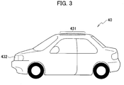
- the light device 43 includes roof lights 431 and turn signals 432, for example.
- the light device 43 illustrated is an example, and is only required to be a light-emitting device that is mounted on the vehicle and emits light visually recognized by people present around the vehicle 40.
- the roof lights 432 are installed along the edges of the roof (the edges on the four sides) of the vehicle 40, as illustrated in Fig. 3 .
- the roof lights 431 include, for example, but not necessarily, a plurality of light-emitting diodes (LEDs).
- the turn signals 432 are installed in the vehicle 40 on the right and left sides, as illustrated in Fig. 3 .
- the turn signals 432 indicate the traveling direction of the vehicle 40 by blinking.
- the controller 45 functions as a plurality of information processing circuits, as in the case of the controller 23.
- the controller 45 includes a vehicle control unit 451 and a lighting control unit 452 as the information processing circuits.
- the vehicle control unit 451 controls the vehicle 40 by means of known techniques.
- the vehicle control unit 451 controls a brake actuator, an accelerator actuator, and a steering actuator, for example, in accordance with pieces of information acquired by various kinds of sensors (such as a camera and a laser rangefinder) mounted on the vehicle 40.
- the control by the vehicle control unit 451 enables the autonomous driving.
- the lighting control unit 452 turns on or turns off the light device 43 in accordance with signals received from the computer 20.
- Fig. 4 an example of operation of the computer 20 is described below with reference to Fig. 4 .
- the following case is described on the assumption that the user 50 has reserved the vehicle 40, and the computer 20 receives the information on the reservation from the terminal device 60.
- the computer 20 sends, to the vehicle 40, a riding location at which the user 50 is to get on and a traveling route to the riding location in accordance with the reservation information.
- the vehicle 40 autonomously travels toward the riding location acquired from the computer 20.
- step S101 the position acquisition unit 232 acquires the positional information of the vehicle 40 from the GPS receiver 42.
- the process proceeds to step S103, and the position acquisition unit 232 acquires the positional information of the terminal device 60 from the GPS receiver 62.
- step S105 The process proceeds to step S105, and the position acquisition unit 232 acquires the map information from the map database 221.
- the process proceeds to step S107, and the position acquisition unit 232 determines whether the distance between the terminal device 60 and the vehicle 40 is a predetermined value or less in accordance with the positional information of the terminal device 60 and the positional information of the vehicle 40.
- the process proceeds to step S113.
- the process is on standby.
- the distance L illustrated in Fig. 5 is a distance between the terminal device 60 and the vehicle 40.
- the distance between the terminal device 60 and the vehicle 40 determined to be the predetermined value or less herein refers to a case in which the distance L illustrated in Fig. 5 is in a range of 10 meters to 30 meters, for example.
- the situation illustrated in Fig. 5 indicates that the process in step S 109 in Fig. 4 is determined to be YES.
- step S109 When the process in step S109 is determined to be YES, the process then proceeds to step S113, and the lighting management unit 233 outputs, to the terminal device 60, the allowing information indicating that the operation on the light device 43 is allowed.
- the lighting management unit 233 may send, to the terminal device 60, a signal for causing the display 63 to display the allowing information.
- the lighting management unit 233 may control an application preliminarily installed in the terminal device 60 to cause the display 63 to display the allowing information.
- Fig. 6 illustrates an example of the allowing information displayed on the display 63. As illustrated in Fig. 6 , the allowing information includes the lighting direction part 64 (64a to 64d). The user 50 operates the respective lighting direction parts 63a to 64d to give the direction to turn on the light device 43 (Yes in step S115).
- the operation by the user 50 includes an operation of tapping the display 63 (a touch panel) and an operation of swiping the display 63.
- the terminal device 60 sends, to the lighting management unit 233, a signal indicating that the user 50 has operated the lighting direction part 64a.
- the lighting management unit 233 receives response information indicating that the user 50 has responded to the allowing information input to the terminal device 60.
- the lighting management unit 233 sends, to the vehicle 40 (the lighting control unit 452), the lighting direction information indicating the direction for turning on the light device 43, in accordance with the response information (in step S117). As illustrated in Fig.
- the lighting control unit 452 when receiving the lighting direction information, causes the light device 43 (the roof lights 431) to be turned on. Since the operation (the direction) by the user 50 causes the roof lights 431 to be turned on, the user 50 can intuitively identify the vehicle 40 as the one that he/she has reserved.
- the same processing is executed when the user 50 swipes the lighting direction part 64c or 64d.
- the roof lights 431 are turned off.
- the process is on standby.
- the color used for the lighting of the roof lights 431 is set on the computer 20 side.
- the user 50 cannot set the color for the lighting of the roof lights 431.
- the reason for this is that, if the user 50 sets the color for the lighting of the roof lights 431, the color set by the user 50 could conform to the color set by other users. This impedes the identification of the reserved vehicle (the vehicle 40).
- the computer 20 thus sets the color so as not to conform to the color set by other adjacent users.
- the color of the roof lights of the vehicle icon indicated in Fig. 6 and the color of the roof lights 431 when actually turned on are set to be the same. According to the present embodiment, since the operation (the direction) by the user 50 causes the roof lights 431 to be turned on with the same color as the color displayed on the display 63, the user 50 can intuitively identify the vehicle 40 as the one that he/she has reserved.
- step S201 the GPS receiver 62 detects the position of the terminal device 60.
- the process proceeds to step S203, and the terminal device 60 (the communication unit 61) sends the positional information of the terminal device 60 to the computer 20.
- the process proceeds to step S205, and the terminal device 60, when receiving the allowing information from the lighting management unit 233 (Yes in step S205), receives the operation performed by the user 50.
- the terminal device 60 sends, to the lighting management unit 233, the signal indicating that the user 50 has operated the lighting direction part 64 (in step S207).
- the process is on standby.
- step S301 the GPS receiver 42 detects the position of the vehicle 40.
- step S303 the vehicle 40 (the communication unit 41) sends the positional information of the vehicle 40 to the computer 20.
- step S305 the lighting control unit 452, when receiving the lighting direction information from the lighting management unit 233 (Yes in step S305), turns on the light device 43 (the roof lights 431) (in step S307).
- step S305 the lighting control unit 452 does not receive the lighting direction information from the lighting management unit 233 (No in step S305), the process is on standby.
- the lighting management unit 233 may output the allowing information to the terminal device 60.
- the riding location 70 is a location at which the user 50 is to get on the vehicle 40, as illustrated in Fig. 10 , and is a stopping place or a parking place, for example.
- the riding location 70 is set at the reservation timing.
- the position of the riding location 70, the position of the user 50 (the position of the terminal device 60), and the position of the vehicle 40 are displayed on the terminal device 60.
- Reference numeral 80 shown in Fig. 9 indicates the predetermined range around the riding location 70.
- the shape of the predetermined range is circular, for example.
- the predetermined range 80 may be either displayed on the terminal device 60 or not. As illustrated in Fig. 9 , when the user 50 and the vehicle 40 are coming close to the riding location 70, and the terminal device 60 and the vehicle 40 are thus present within the predetermined range 80, the lighting management unit 233 may output the allowing information to the terminal device 60. The user 50, when recognizing the allowing information, operates the lighting direction part 64a so that the roof lights 431 are turned on (refer to Fig. 10 ). The user 50 thus can identify the vehicle 40 as the one that he/she has reserved.
- the target to be turned on is not limited to the roof lights 431.
- the lighting control unit 452 may blink the turn signals 432.
- the lighting management unit 233 may provide the number of times of blinking of the turn signals 432 so as to be chosen by the user 50, as one example of the allowing information.
- the turn signals 432 blink one time, as illustrated in Fig. 12 .
- the turn signals 432 blink two times.
- the turn signals 432 blink three times.
- the turn signals 432 blink four times. Since the number of times of blinking of the turn signals 432 changes depending on the choice of the user 50, the user 50 can intuitionally identify the vehicle 40 as the one that he/she has reserved.
- the lighting control unit 452 may vary the turn signals 432 to be turned on depending on the position of the user 50 (the position of the terminal device 60). As illustrated in Fig. 12 , the lighting control unit 452 may turn on and blink the turn signals 432 on the left side when the user 50 (the terminal device 60) is located on the front left side of the vehicle 40. Blinking the turn signals 432 at the position corresponding to the direction of the user 50 allows the user 50 to easily recognize the turn signals 432 blinking.
- the lighting control unit 452 may turn on one of the roof lights 431 at the position corresponding to the direction of the user 50. For example, as illustrated in Fig. 12 , the lighting control unit 452 may turn on the roof light 431 mounted at the left edge of the roof of the vehicle 40.
- the reserved vehicle control system 10 can achieve the following functional effects.
- the computer 20 acquires the positional information of the vehicle 40 from the GPS receiver 42, and acquires the positional information of the terminal device 60 from the GPS receiver 62.
- the computer 20 determines whether the distance between the terminal device 60 and the vehicle 40 is the predetermined value or less in accordance with the positional information of the terminal device 60 and the positional information of the vehicle 40.
- the computer 20 outputs, to the terminal device 60, the allowing information indicating that the operation on the light device 43 mounted on the vehicle 40 is allowed.
- the computer 20 turns on the light device 43 in accordance with the response information (the operation by the user 50) input to the terminal device 60 in response to the allowing information (refer to Fig. 5 ).
- the computer 20 controls the lighting state of the light device 43 depending on the operation performed on the terminal device 60 having received the allowing information. Since the light device 43 is turned on through the operation by the user 50, the user 50 can intuitively identify the vehicle 40 as the one that he/she has reserved. Further, since there is no need to install a display on the vehicle 40, as disclosed in Patent Document 1, the present embodiment has the advantage in cost.
- the user 50 thus can intuitively identify the vehicle 40 as the one that he/she has reserved.
- the computer 20 may turn on the light device 43 located at the position corresponding to the direction of the user 50. This allows the user 50 to easily recognize the light device 43 being turned on.
- the respective functions described in the above embodiment can be implemented in single or plural processing circuits.
- the respective processing circuits include a programmed processing device, such as a processing device including an electric circuit.
- the respective processing circuits also include an application-specific integrated circuit (ASIC) configured to execute the functions described above, and other devices such as circuit components.
- ASIC application-specific integrated circuit
- the reserved vehicle control system 10 can improve the functions of the computer.
- the computer 20 may inhibit the user 50 from turning on the light device 43 depending on the distance between the terminal device 60 and the vehicle 40.
- the computer 20 may inhibit the user 50 from turning on the light device 43.
- An example in which the distance between the terminal device 60 and the vehicle 40 is much shorter than the distance L illustrated in Fig. 5 is a case in which the user 50 has already got in the vehicle 40. In such a case, turning on the light device 43 has no meaning, since the user 50 has already identified the vehicle 40. Instead, turning on the light device 43 in such a situation wastes excessive energy.
- the computer 20 thus may inhibit the user 50 from executing the operation for turning on the light device 43 depending on the distance between the terminal device 60 and the vehicle 40. This can avoid excessive energy to be consumed.
- the computer 20 may also turn on the light device 43 when the user 50 is present within a predetermined angle in the traveling direction of the vehicle 40.
- the displaying example of the terminal device 60 is not limited to the case illustrated in Fig. 6 .
- the display which is inactive before receiving the allowing information may be turned to be active after receiving the allowing information.
- the computer 20 may also output, to the terminal device 60, the allowing information indicating that the operation performed on the light device 43 is allowed when the distance between the terminal device 60 and the vehicle 40 is the predetermined value or less, and when the user 50 can visually confirm the vehicle 40.
- This case is described below with reference to Fig. 13 .
- the process in steps S401 to S409 and steps S413 to S417 shown in Fig. 13 is the same as the process in steps S101 to S109 and steps S113 to S117, and overlapping explanations are not repeated below.
- step S411 shown in Fig. 13 the position acquisition unit 232 determines whether the user 50 can visually confirm the vehicle 40, in accordance with the map information acquired in step S405, the positional information of the terminal device 60, and the positional information of the vehicle 40.
- the user 50 sometimes cannot visually confirm the vehicle 40 if there is a construction (such as a large-sized building) between the terminal device 60 and the vehicle 40 although the distance between the terminal device 60 and the vehicle 40 is the predetermined value or less.
- the position acquisition unit 232 determines whether there is a construction obstructing the field of vision of the user 50 between the user 50 and the vehicle 40 in accordance with the map information acquired in step S405.
- the controller 23 determines that the user 50 can visually confirm the vehicle 40 (Yes in step S411).
- the process returns to step S409.
- the situation illustrated in Fig. 5 is the case in which the user 50 can visually confirm the vehicle 40. Since the light device 43 is turned on through the operation by the user 50 when the user 50 can visually confirm the vehicle 40, the user 50 can intuitively identify the vehicle 40 as the one that he/she has reserved.
- the above example has been illustrated with the case of using the terminal device 60 when the user 50 reserves the vehicle 40 and gives the direction to turn on the light device 43, but is not limited to this case.
- the reservation of the vehicle 40 may be made by another terminal device instead of the terminal device 60.
- the CPU installed in the terminal device 60 may be substituted for the computer 20 to execute the functions of the computer 20.
- the CPU installed in the vehicle 40 may be substituted for the computer 20 to execute the functions of the computer 20.
Landscapes
- Physics & Mathematics (AREA)
- General Physics & Mathematics (AREA)
- Engineering & Computer Science (AREA)
- Business, Economics & Management (AREA)
- Tourism & Hospitality (AREA)
- General Health & Medical Sciences (AREA)
- General Business, Economics & Management (AREA)
- Signal Processing (AREA)
- Economics (AREA)
- Health & Medical Sciences (AREA)
- Human Resources & Organizations (AREA)
- Marketing (AREA)
- Computer Networks & Wireless Communication (AREA)
- Theoretical Computer Science (AREA)
- Strategic Management (AREA)
- Operations Research (AREA)
- Quality & Reliability (AREA)
- Entrepreneurship & Innovation (AREA)
- Computing Systems (AREA)
- Development Economics (AREA)
- Medical Informatics (AREA)
- Primary Health Care (AREA)
- Traffic Control Systems (AREA)
- Lighting Device Outwards From Vehicle And Optical Signal (AREA)
- Navigation (AREA)
Abstract
Description
- The present invention relates to a reserved vehicle control method, a reserved vehicle control device, and a reserved vehicle control system.
- Methods are known that identify an autonomous vehicle that a user has reserved (Patent Document 1). The invention disclosed in Patent Document 1 causes a display installed on a door of the autonomous vehicle and a smartphone that the user uses to simultaneously display the same figure. The user compares to determine whether the figure displayed on the smartphone is the same as the figure displayed on the display on the door, so as to identify the reserved autonomous vehicle.
- Patent Document 1:
US 9494938 - The invention disclosed in Patent Document 1 requires the user to compare to determine whether the figure displayed on the smartphone is the same as the figure displayed on the display on the door, since a server sets the figure to be displayed. This impedes the user's intuitive recognition in identifying the reserved autonomous vehicle.
- In view of the foregoing problem, the present invention provides a reserved vehicle control method, a reserved vehicle control device, and a reserved vehicle control system enabling a user to intuitively identify a reserved autonomous vehicle.
- A reserved vehicle control method according to an aspect of the present invention includes a step of acquiring positional information of a terminal device, a step of acquiring positional information of a reserved vehicle, a step of determining whether a distance between the terminal device and the reserved vehicle is a predetermined value or less, in accordance with the positional information of the terminal device and the positional information of the reserved vehicle, and a step of outputting, to the terminal device, allowing information indicating that an operation on a light-emitting device mounted on the reserved vehicle is allowed, when determining that the distance between the terminal device and the reserved vehicle is the predetermined value or less.
- The present invention can enable a user to intuitively identify a reserved autonomous vehicle.
-
- [
Fig. 1] Fig. 1 is a schematic diagram illustrating a reserved vehicle identifying system according to an embodiment of the present invention. - [
Fig. 2] Fig. 2 is a schematic configuration diagram illustrating the reserved vehicle identifying system according to the embodiment of the present invention. - [
Fig. 3] Fig. 3 is a diagram for explaining a light device according to the embodiment of the present invention. - [
Fig. 4] Fig. 4 is a flowchart illustrating an example of operation of a computer according to the embodiment of the present invention. - [
Fig. 5] Fig. 5 is a diagram for explaining an example of lighting of the light device in one example. - [
Fig. 6] Fig. 6 is a diagram for explaining allowing information output to a terminal device in one example. - [
Fig. 7] Fig. 7 is a flowchart illustrating an example of operation of the terminal device according to the embodiment of the present invention. - [
Fig. 8] Fig. 8 is a flowchart illustrating an example of operation of a vehicle according to the embodiment of the present invention. - [
Fig. 9] Fig. 9 is a diagram for explaining allowing information output to the terminal device in one example. - [
Fig. 10] Fig. 10 is a partly enlarged diagram ofFig. 9 . - [
Fig. 11] Fig. 11 is a diagram for explaining allowing information output to the terminal device in one example. - [
Fig. 12] Fig. 12 is a diagram for explaining an example of lighting of the light device in one example. - [
Fig. 13] Fig. 13 is a flowchart illustrating an example of operation of a computer according to another embodiment of the present invention. - One or more embodiments of the present invention will be described below with reference to the drawings. The same elements illustrated in the descriptions of the drawings are indicated by the same reference numerals, and overlapping explanations are not made below.
- A configuration of a reserved
vehicle control system 10 is described below with reference toFig. 1 . As shown inFig. 1 , the reservedvehicle control system 10 includes acomputer 20, acommunication network 30,vehicles user 50, and aterminal device 60 that theuser 50 possesses.Fig. 1 illustrates the three vehicles, but the number of the vehicles is not limited to this case. The reservedvehicle control system 10 may include four or more vehicles. The reservedvehicle control system 10 may include only a single vehicle. - The computer 20 (a reserved vehicle control device) communicates with the
vehicles terminal device 60 via thecommunication network 30. Thecomputer 20 is a general-purpose computer, for example, and includes a processor including a CPU and a memory such as a read-only memory (ROM) and a random-access memory (RAM). The CPU reads out a program stored in the ROM and the like to the RAM to execute the program. Part of (or all of) the reservedvehicle control system 10 including the functions of thecomputer 20 described below may be implemented by an application (such as software as a service (SaaS)) set in thecommunication network 30. Thecomputer 20 may also be a server. - The
communication network 30 may be configured in either a wireless manner or a wired manner, or in both wireless and wired manners, or may include the Internet. According to the present embodiment, thecomputer 20, thevehicles terminal device 60 are connected to thecommunication network 30 in wireless communications. - The
vehicles respective vehicles vehicles vehicles respective vehicles vehicles - The
user 50 uses theterminal device 60 to reserve thevehicle 40 from a plurality of vehicles (thevehicles vehicle 40 is referred to as a reserved vehicle. Thecomputer 20 receives the information on the reservation from theterminal device 60. Thecomputer 20 sends, to thevehicle 40, a location at which theuser 50 is to get on the vehicle 40 (referred to below as a "riding location") and a traveling route to the riding location, in accordance with the reservation information. Thecomputer 20 further sends, to thevehicle 40, a destination of theuser 50 and a traveling route to the destination in accordance with the reservation information. Thevehicle 40 autonomously travels to the riding location in accordance with the information acquired from thecomputer 20. Thevehicle 40 allows theuser 50 to get in at the riding location to transport theuser 50 to the destination. Thevehicle 40 then autonomously travels back to a predetermined standby point. According to the present embodiment, a user ID for identifying theuser 50 is linked with a vehicle ID for identifying thevehicle 40 by thecomputer 20. Theterminal device 60 is a device that theuser 50 can carry around, and can be a smartphone or a tablet, for example. The user ID as used herein is thus an ID allotted to theterminal device 60. - Next, the
computer 20, thevehicle 40, and theterminal device 60 are described in detail below with reference toFig. 2 . - As shown in
Fig. 2 , thecomputer 20 includes acommunication unit 21, astorage device 22, and acontroller 23. Thevehicle 40 includes aGPS receiver 42, alight device 43, and acontroller 45. Theterminal device 60 includes acommunication unit 61, aGPS receiver 62, adisplay 63, and alighting direction part 64. - The
communication unit 21, thecommunication unit 41, and thecommunication unit 61 are each an interface connected to thecommunication network 30 to send and receive data. According to the present embodiment, the communication between thevehicle 40 and theterminal device 60 is made via thecomputer 20. Thevehicle 40 and theterminal device 60 do not directly communicate with each other. - The
storage device 22 includes single or plural random-access memories (RAMs) serving as accessible storage devices. Amap database 221 is stored in thestorage device 22. Themap database 221 includes various kinds of data necessary for a route guidance such as road information and facility information. Themap database 221 also includes other information on roads, such as the number of lanes, road boundaries (such as white lines and road defining lines), landmarks, and curbs. - The controller 23 (a control unit) functions as a plurality of information processing circuits. While the present embodiment is illustrated with a case in which the software is installed to fabricate the respective information processing circuits included in the
computer 20, dedicated hardware for executing each information processing as described below can be prepared to fabricate the information processing circuits. The respective information processing circuits may be implemented by individual hardware. Thecontroller 23 includes areservation management unit 231, aposition acquisition unit 232, and alighting management unit 233, as the information processing circuits. - The
reservation management unit 231 manages the reservation information acquired from theuser 50. Theposition acquisition unit 232 acquires positional information of thevehicle 40 from the vehicle 40 (the communication unit 41). Theposition acquisition unit 232 also acquires positional information of theterminal device 60 from the terminal device 60 (the communication unit 61). - The
lighting management unit 233 outputs, to theterminal device 60, allowing information indicating that the operation on thelight device 43 is allowed. The specific explanations are made below. - The
GPS receiver 42 receives radio waves from satellites so as to detect the position (such as a longitude and a latitude) of thevehicle 40 on the ground. Similarly, theGPS receiver 62 receives radio waves from satellites so as to detect the position (such as a longitude and a latitude) of theterminal device 60 on the ground. - The
light device 43 is a device mounted on thevehicle 40 to notify drivers on other vehicles or pedestrians of the information (the position, the braking, and the traveling direction) of thevehicle 40. Thelight device 43 includesroof lights 431 andturn signals 432, for example. Thelight device 43 illustrated is an example, and is only required to be a light-emitting device that is mounted on the vehicle and emits light visually recognized by people present around thevehicle 40. - The roof lights 432 are installed along the edges of the roof (the edges on the four sides) of the
vehicle 40, as illustrated inFig. 3 . Theroof lights 431 include, for example, but not necessarily, a plurality of light-emitting diodes (LEDs). - The turn signals 432 are installed in the
vehicle 40 on the right and left sides, as illustrated inFig. 3 . The turn signals 432 indicate the traveling direction of thevehicle 40 by blinking. - The
controller 45 functions as a plurality of information processing circuits, as in the case of thecontroller 23. Thecontroller 45 includes avehicle control unit 451 and alighting control unit 452 as the information processing circuits. - The
vehicle control unit 451 controls thevehicle 40 by means of known techniques. In particular, thevehicle control unit 451 controls a brake actuator, an accelerator actuator, and a steering actuator, for example, in accordance with pieces of information acquired by various kinds of sensors (such as a camera and a laser rangefinder) mounted on thevehicle 40. The control by thevehicle control unit 451 enables the autonomous driving. - The
lighting control unit 452 turns on or turns off thelight device 43 in accordance with signals received from thecomputer 20. - An example of operation of the reserved
vehicle control system 10 is described below with reference toFig. 4 to Fig. 8 . - First, an example of operation of the
computer 20 is described below with reference toFig. 4 . The following case is described on the assumption that theuser 50 has reserved thevehicle 40, and thecomputer 20 receives the information on the reservation from theterminal device 60. Thecomputer 20 sends, to thevehicle 40, a riding location at which theuser 50 is to get on and a traveling route to the riding location in accordance with the reservation information. Thevehicle 40 autonomously travels toward the riding location acquired from thecomputer 20. - In step S101, the
position acquisition unit 232 acquires the positional information of thevehicle 40 from theGPS receiver 42. The process proceeds to step S103, and theposition acquisition unit 232 acquires the positional information of theterminal device 60 from theGPS receiver 62. - The process proceeds to step S105, and the
position acquisition unit 232 acquires the map information from themap database 221. The process proceeds to step S107, and theposition acquisition unit 232 determines whether the distance between theterminal device 60 and thevehicle 40 is a predetermined value or less in accordance with the positional information of theterminal device 60 and the positional information of thevehicle 40. When the distance between theterminal device 60 and thevehicle 40 is the predetermined value or less (Yes in step S109), the process proceeds to step S113. When the distance between theterminal device 60 and thevehicle 40 is greater than the predetermined value (No in step S109), the process is on standby. - The distance L illustrated in
Fig. 5 is a distance between theterminal device 60 and thevehicle 40. The distance between theterminal device 60 and thevehicle 40 determined to be the predetermined value or less herein refers to a case in which the distance L illustrated inFig. 5 is in a range of 10 meters to 30 meters, for example. The situation illustrated inFig. 5 indicates that the process in step S 109 inFig. 4 is determined to be YES. - When the process in step S109 is determined to be YES, the process then proceeds to step S113, and the
lighting management unit 233 outputs, to theterminal device 60, the allowing information indicating that the operation on thelight device 43 is allowed. When outputting the allowing information, thelighting management unit 233 may send, to theterminal device 60, a signal for causing thedisplay 63 to display the allowing information. Alternatively, thelighting management unit 233 may control an application preliminarily installed in theterminal device 60 to cause thedisplay 63 to display the allowing information.Fig. 6 illustrates an example of the allowing information displayed on thedisplay 63. As illustrated inFig. 6 , the allowing information includes the lighting direction part 64 (64a to 64d). Theuser 50 operates the respective lighting direction parts 63a to 64d to give the direction to turn on the light device 43 (Yes in step S115). - The operation by the
user 50 includes an operation of tapping the display 63 (a touch panel) and an operation of swiping thedisplay 63. When theuser 50 operates thelighting direction part 64a, theterminal device 60 sends, to thelighting management unit 233, a signal indicating that theuser 50 has operated thelighting direction part 64a. In other words, thelighting management unit 233 receives response information indicating that theuser 50 has responded to the allowing information input to theterminal device 60. Thelighting management unit 233 sends, to the vehicle 40 (the lighting control unit 452), the lighting direction information indicating the direction for turning on thelight device 43, in accordance with the response information (in step S117). As illustrated inFig. 5 , thelighting control unit 452, when receiving the lighting direction information, causes the light device 43 (the roof lights 431) to be turned on. Since the operation (the direction) by theuser 50 causes theroof lights 431 to be turned on, theuser 50 can intuitively identify thevehicle 40 as the one that he/she has reserved. - The same processing is executed when the
user 50 swipes thelighting direction part user 50 operates thelighting direction part 64b, theroof lights 431 are turned off. When theuser 50 makes no action (direction) in step 115, the process is on standby. The color used for the lighting of theroof lights 431 is set on thecomputer 20 side. Theuser 50 cannot set the color for the lighting of the roof lights 431. The reason for this is that, if theuser 50 sets the color for the lighting of theroof lights 431, the color set by theuser 50 could conform to the color set by other users. This impedes the identification of the reserved vehicle (the vehicle 40). Thecomputer 20 thus sets the color so as not to conform to the color set by other adjacent users. The color of the roof lights of the vehicle icon indicated inFig. 6 and the color of theroof lights 431 when actually turned on are set to be the same. According to the present embodiment, since the operation (the direction) by theuser 50 causes theroof lights 431 to be turned on with the same color as the color displayed on thedisplay 63, theuser 50 can intuitively identify thevehicle 40 as the one that he/she has reserved. - Next, an example of operation of the
terminal device 60 is described below with reference toFig. 7 . - In step S201, the
GPS receiver 62 detects the position of theterminal device 60. The process proceeds to step S203, and the terminal device 60 (the communication unit 61) sends the positional information of theterminal device 60 to thecomputer 20. The process proceeds to step S205, and theterminal device 60, when receiving the allowing information from the lighting management unit 233 (Yes in step S205), receives the operation performed by theuser 50. When theuser 50 operates thelighting direction part 64, theterminal device 60 sends, to thelighting management unit 233, the signal indicating that theuser 50 has operated the lighting direction part 64 (in step S207). When theterminal device 60 does not receive the allowing information from the lighting management unit 233 (No in step S205), the process is on standby. - Next, an example of operation of the
vehicle 40 is described below with reference toFig. 8 . - In step S301, the
GPS receiver 42 detects the position of thevehicle 40. The process proceeds to step S303, and the vehicle 40 (the communication unit 41) sends the positional information of thevehicle 40 to thecomputer 20. The process proceeds to step S305, and thelighting control unit 452, when receiving the lighting direction information from the lighting management unit 233 (Yes in step S305), turns on the light device 43 (the roof lights 431) (in step S307). When thelighting control unit 452 does not receive the lighting direction information from the lighting management unit 233 (No in step S305), the process is on standby. - As illustrated in
Fig. 9 , when theterminal device 60 and thevehicle 40 are located within a predetermined range around the ridinglocation 70, thelighting management unit 233 may output the allowing information to theterminal device 60. The ridinglocation 70 is a location at which theuser 50 is to get on thevehicle 40, as illustrated inFig. 10 , and is a stopping place or a parking place, for example. The ridinglocation 70 is set at the reservation timing. As illustrated inFig. 9 , the position of the ridinglocation 70, the position of the user 50 (the position of the terminal device 60), and the position of thevehicle 40 are displayed on theterminal device 60.Reference numeral 80 shown inFig. 9 indicates the predetermined range around the ridinglocation 70. The shape of the predetermined range is circular, for example. Thepredetermined range 80 may be either displayed on theterminal device 60 or not. As illustrated inFig. 9 , when theuser 50 and thevehicle 40 are coming close to the ridinglocation 70, and theterminal device 60 and thevehicle 40 are thus present within thepredetermined range 80, thelighting management unit 233 may output the allowing information to theterminal device 60. Theuser 50, when recognizing the allowing information, operates thelighting direction part 64a so that theroof lights 431 are turned on (refer toFig. 10 ). Theuser 50 thus can identify thevehicle 40 as the one that he/she has reserved. - While the above example is illustrated with the lighting of the
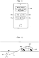
roof lights 431, the target to be turned on is not limited to the roof lights 431. As illustrated inFig. 11 and Fig. 12 , thelighting control unit 452 may blink the turn signals 432. - As illustrated in
Fig. 11 , thelighting management unit 233 may provide the number of times of blinking of the turn signals 432 so as to be chosen by theuser 50, as one example of the allowing information. When theuser 50 operates thelighting direction part 64e illustrated inFig. 11 , the turn signals 432 blink one time, as illustrated inFig. 12 . Similarly, when theuser 50 operates thelighting direction part 64f, the turn signals 432 blink two times. Similarly, when theuser 50 operates thelighting direction part 64g, the turn signals 432 blink three times. Similarly, when theuser 50 operates thelighting direction part 64h, the turn signals 432 blink four times. Since the number of times of blinking of the turn signals 432 changes depending on the choice of theuser 50, theuser 50 can intuitionally identify thevehicle 40 as the one that he/she has reserved. - The
lighting control unit 452 may vary the turn signals 432 to be turned on depending on the position of the user 50 (the position of the terminal device 60). As illustrated inFig. 12 , thelighting control unit 452 may turn on and blink the turn signals 432 on the left side when the user 50 (the terminal device 60) is located on the front left side of thevehicle 40. Blinking the turn signals 432 at the position corresponding to the direction of theuser 50 allows theuser 50 to easily recognize the turn signals 432 blinking. Thelighting control unit 452 may turn on one of theroof lights 431 at the position corresponding to the direction of theuser 50. For example, as illustrated inFig. 12 , thelighting control unit 452 may turn on theroof light 431 mounted at the left edge of the roof of thevehicle 40. - As described above, the reserved
vehicle control system 10 according to the present embodiment can achieve the following functional effects. - The
computer 20 acquires the positional information of thevehicle 40 from theGPS receiver 42, and acquires the positional information of theterminal device 60 from theGPS receiver 62. Thecomputer 20 determines whether the distance between theterminal device 60 and thevehicle 40 is the predetermined value or less in accordance with the positional information of theterminal device 60 and the positional information of thevehicle 40. When the distance between theterminal device 60 and thevehicle 40 is the predetermined value or less, thecomputer 20 outputs, to theterminal device 60, the allowing information indicating that the operation on thelight device 43 mounted on thevehicle 40 is allowed. Thecomputer 20 turns on thelight device 43 in accordance with the response information (the operation by the user 50) input to theterminal device 60 in response to the allowing information (refer toFig. 5 ). Namely, thecomputer 20 controls the lighting state of thelight device 43 depending on the operation performed on theterminal device 60 having received the allowing information. Since thelight device 43 is turned on through the operation by theuser 50, theuser 50 can intuitively identify thevehicle 40 as the one that he/she has reserved. Further, since there is no need to install a display on thevehicle 40, as disclosed in Patent Document 1, the present embodiment has the advantage in cost. - The
computer 20, when determining that theterminal device 60 and thevehicle 40 are present within thepredetermined range 80 around the location (the riding location 70) at which theuser 50 is to get on thevehicle 40, may output the allowing information to the terminal device 60 (refer toFig. 9 andFig. 10 ). Theuser 50 thus can intuitively identify thevehicle 40 as the one that he/she has reserved. - The
computer 20 may turn on thelight device 43 located at the position corresponding to the direction of theuser 50. This allows theuser 50 to easily recognize thelight device 43 being turned on. - The respective functions described in the above embodiment can be implemented in single or plural processing circuits. The respective processing circuits include a programmed processing device, such as a processing device including an electric circuit. The respective processing circuits also include an application-specific integrated circuit (ASIC) configured to execute the functions described above, and other devices such as circuit components. The reserved
vehicle control system 10 can improve the functions of the computer. - While the present invention has been described above by reference to the embodiment, it should be understood that the present invention is not intended to be limited to the descriptions and the drawings composing part of this disclosure. Various alternative embodiments, examples, and technical applications will be apparent to those skilled in the art according to this disclosure.
- For example, while the above embodiment has been illustrated with the case in which the
computer 20 allows theuser 50 to execute the operation for turning on thelight device 43, thecomputer 20 may inhibit theuser 50 from turning on thelight device 43 depending on the distance between theterminal device 60 and thevehicle 40. For example, when the distance between theterminal device 60 and thevehicle 40 is much shorter than the distance L illustrated inFig. 5 , thecomputer 20 may inhibit theuser 50 from turning on thelight device 43. An example in which the distance between theterminal device 60 and thevehicle 40 is much shorter than the distance L illustrated inFig. 5 is a case in which theuser 50 has already got in thevehicle 40. In such a case, turning on thelight device 43 has no meaning, since theuser 50 has already identified thevehicle 40. Instead, turning on thelight device 43 in such a situation wastes excessive energy. Thecomputer 20 thus may inhibit theuser 50 from executing the operation for turning on thelight device 43 depending on the distance between theterminal device 60 and thevehicle 40. This can avoid excessive energy to be consumed. - The
computer 20 may also turn on thelight device 43 when theuser 50 is present within a predetermined angle in the traveling direction of thevehicle 40. - The displaying example of the
terminal device 60 is not limited to the case illustrated inFig. 6 . For example, as another displaying example, the display which is inactive before receiving the allowing information may be turned to be active after receiving the allowing information. - The
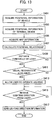
computer 20 may also output, to theterminal device 60, the allowing information indicating that the operation performed on thelight device 43 is allowed when the distance between theterminal device 60 and thevehicle 40 is the predetermined value or less, and when theuser 50 can visually confirm thevehicle 40. This case is described below with reference toFig. 13 . The process in steps S401 to S409 and steps S413 to S417 shown inFig. 13 is the same as the process in steps S101 to S109 and steps S113 to S117, and overlapping explanations are not repeated below. - In step S411 shown in
Fig. 13 , theposition acquisition unit 232 determines whether theuser 50 can visually confirm thevehicle 40, in accordance with the map information acquired in step S405, the positional information of theterminal device 60, and the positional information of thevehicle 40. Theuser 50 sometimes cannot visually confirm thevehicle 40 if there is a construction (such as a large-sized building) between theterminal device 60 and thevehicle 40 although the distance between theterminal device 60 and thevehicle 40 is the predetermined value or less. Theposition acquisition unit 232 then determines whether there is a construction obstructing the field of vision of theuser 50 between theuser 50 and thevehicle 40 in accordance with the map information acquired in step S405. When there is no construction obstructing the field of vision of theuser 50 between theuser 50 and thevehicle 40, thecontroller 23 determines that theuser 50 can visually confirm the vehicle 40 (Yes in step S411). When thecontroller 23 determines that theuser 50 cannot visually confirm thevehicle 40, the process returns to step S409. The situation illustrated inFig. 5 is the case in which theuser 50 can visually confirm thevehicle 40. Since thelight device 43 is turned on through the operation by theuser 50 when theuser 50 can visually confirm thevehicle 40, theuser 50 can intuitively identify thevehicle 40 as the one that he/she has reserved. - The above example has been illustrated with the case of using the
terminal device 60 when theuser 50 reserves thevehicle 40 and gives the direction to turn on thelight device 43, but is not limited to this case. The reservation of thevehicle 40 may be made by another terminal device instead of theterminal device 60. The CPU installed in theterminal device 60 may be substituted for thecomputer 20 to execute the functions of thecomputer 20. Alternatively, the CPU installed in thevehicle 40 may be substituted for thecomputer 20 to execute the functions of thecomputer 20. -
- 10
- RESERVED VEHICLE CONTROL SYSTEM
- 20
- COMPUTER
- 21, 41, 61
- COMMUNICATION UNIT
- 22
- STORAGE DEVICE
- 23, 45
- CONTROLLER
- 30
- COMMUNICATION NETWORK
- 40, 40a,
- 40b VEHICLE
- 42, 62
- GPS RECEIVER
- 43
- LIGHT DEVICE
- 50
- USER
- 60
- TERMINAL DEVICE
- 63
- DISPLAY
- 64, 64a to 64h
- LIGHTING DIRECTION PART
- 221
- MAP DATABASE
- 231
- RESERVATION MANAGEMENT UNIT
- 232
- POSITION ACQUISITION UNIT
- 233
- LIGHTING MANAGEMENT UNIT
- 431
- ROOF LIGHT
- 432
- TURN SIGNAL
- 451
- VEHICLE CONTROL UNIT
- 452
- LIGHTING CONTROL UNIT
Claims (6)
- A reserved vehicle control method of a reserved vehicle control device capable of communicating with a terminal device that a user possesses and a plurality of vehicles, and controlling a reserved vehicle reserved by the user from the plural vehicles through the terminal device in accordance with an operation performed on the terminal device, the method comprising:acquiring positional information of the terminal device;acquiring positional information of the reserved vehicle;determining whether a distance between the terminal device and the reserved vehicle is a predetermined value or less, in accordance with the positional information of the terminal device and the positional information of the reserved vehicle; andoutputting, to the terminal device, allowing information indicating that an operation on a light-emitting device mounted on the reserved vehicle is allowed, when determining that the distance between the terminal device and the reserved vehicle is the predetermined value or less.
- A reserved vehicle control device comprising a control unit capable of communicating with a terminal device that a user possesses and a plurality of vehicles, and controlling a reserved vehicle reserved by the user from the plural vehicles through the terminal device in accordance with an operation performed on the terminal device,
the control unit being configured to:acquire positional information of the terminal device;acquire positional information of the reserved vehicle;determine whether a distance between the terminal device and the reserved vehicle is a predetermined value or less, in accordance with the positional information of the terminal device and the positional information of the reserved vehicle; andoutput, to the terminal device, allowing information indicating that an operation on a light-emitting device mounted on the reserved vehicle is allowed, when determining that the distance between the terminal device and the reserved vehicle is the predetermined value or less. - A reserved vehicle control system comprising a terminal device that a user possesses, a plurality of vehicles, and a computer capable of communicating with the terminal device and the plural vehicles, the system being configured to control a reserved vehicle reserved by the user from the plural vehicles through the terminal device in accordance with an operation performed on the terminal device,
the computer being configured to:acquire positional information of the terminal device;acquire positional information of the reserved vehicle;determine whether a distance between the terminal device and the reserved vehicle is a predetermined value or less, in accordance with the positional information of the terminal device and the positional information of the reserved vehicle; andoutput, to the terminal device, allowing information indicating that an operation on a light-emitting device mounted on the reserved vehicle is allowed, when determining that the distance between the terminal device and the reserved vehicle is the predetermined value or less. - The reserved vehicle control system according to claim 3, wherein the computer controls light emission of the light-emitting device in accordance with the operation performed on the terminal device having received the allowing information.
- The reserved vehicle control system according to claim 3 or 4, wherein the computer outputs the allowing information to the terminal device when the terminal device and the reserved vehicle are determined to be present within a predetermined range around a location at which the user is to get on the reserved vehicle.
- The reserved vehicle control system according to any one of claims 3 to 5, wherein the computer turns on the light-emitting device mounted at a position corresponding to a direction of the terminal device.
Applications Claiming Priority (1)
| Application Number | Priority Date | Filing Date | Title |
|---|---|---|---|
| PCT/IB2018/001175 WO2020058738A1 (en) | 2018-09-21 | 2018-09-21 | Reserved vehicle control method, reserved vehicle control device, and reserved vehicle control system |
Publications (3)
| Publication Number | Publication Date |
|---|---|
| EP3855407A1 true EP3855407A1 (en) | 2021-07-28 |
| EP3855407A4 EP3855407A4 (en) | 2021-09-01 |
| EP3855407B1 EP3855407B1 (en) | 2024-04-10 |
Family
ID=69888392
Family Applications (1)
| Application Number | Title | Priority Date | Filing Date |
|---|---|---|---|
| EP18934301.5A Active EP3855407B1 (en) | 2018-09-21 | 2018-09-21 | Reserved vehicle control method, reserved vehicle control device, and reserved vehicle control system |
Country Status (7)
| Country | Link |
|---|---|
| US (1) | US11670174B2 (en) |
| EP (1) | EP3855407B1 (en) |
| JP (1) | JP7133635B2 (en) |
| CN (1) | CN112740297B (en) |
| BR (1) | BR112021005203A2 (en) |
| MX (1) | MX2021003177A (en) |
| WO (1) | WO2020058738A1 (en) |
Families Citing this family (6)
| Publication number | Priority date | Publication date | Assignee | Title |
|---|---|---|---|---|
| WO2021192701A1 (en) * | 2020-03-25 | 2021-09-30 | ボッシュ株式会社 | Vehicle-position identification system and vehicle-position identification device |
| WO2021214505A1 (en) * | 2020-04-24 | 2021-10-28 | 日産自動車株式会社 | Stopping position control method, stopping position control device, and stopping position control system |
| EP4224288B1 (en) * | 2022-02-07 | 2025-12-17 | Robert Ohrenstein | Gaze direction determination apparatus |
| KR102907962B1 (en) * | 2022-02-21 | 2026-01-02 | 영남대학교 산학협력단 | Active notice device for safety of vehicle and pedestrian |
| CN117475662A (en) * | 2022-12-27 | 2024-01-30 | 上海汽车工业(集团)有限公司 | Information prompting method and information prompting device |
| US12403827B2 (en) * | 2023-01-19 | 2025-09-02 | Pedestrian Safety Solutions, Llc | Environmentally sealed visual display assembly and process incorporating individual or stacked LED strips, processor and accelerometer components |
Family Cites Families (18)
| Publication number | Priority date | Publication date | Assignee | Title |
|---|---|---|---|---|
| JP3813073B2 (en) | 2001-08-22 | 2006-08-23 | ダイハツ工業株式会社 | Shared vehicle management system |
| JP2004157698A (en) * | 2002-11-06 | 2004-06-03 | Nec Corp | Taxi service system, mobile terminal and taxi service method and program used for them |
| US20160027307A1 (en) * | 2005-12-23 | 2016-01-28 | Raj V. Abhyanker | Short-term automobile rentals in a geo-spatial environment |
| US9494938B1 (en) * | 2014-04-03 | 2016-11-15 | Google Inc. | Unique signaling for autonomous vehicles to preserve user privacy |
| JP6508582B2 (en) | 2014-07-24 | 2019-05-08 | パナソニックIpマネジメント株式会社 | Vehicle communication apparatus and vehicle communication system |
| JP6354542B2 (en) | 2014-11-26 | 2018-07-11 | 株式会社デンソー | Automatic vehicle driving system |
| US10215574B2 (en) * | 2015-08-06 | 2019-02-26 | Uber Technologies, Inc. | Facilitating rider pick-up for a transport service |
| US9958864B2 (en) * | 2015-11-04 | 2018-05-01 | Zoox, Inc. | Coordination of dispatching and maintaining fleet of autonomous vehicles |
| WO2017106497A1 (en) * | 2015-12-17 | 2017-06-22 | Counterfy Llc | Displayed identifier for a ridesharing service |
| US10824985B2 (en) * | 2016-03-09 | 2020-11-03 | Amazon Technologies, Inc. | Interactive mobile pick-up unit notification |
| US10554783B2 (en) * | 2016-12-30 | 2020-02-04 | Lyft, Inc. | Navigation using proximity information |
| JP6760088B2 (en) | 2017-01-06 | 2020-09-23 | 株式会社デンソー | Electronic key system and in-vehicle device |
| JP7080012B2 (en) * | 2017-02-09 | 2022-06-03 | 日本電産モビリティ株式会社 | Vehicle control system, vehicle control device |
| JP6812955B2 (en) | 2017-02-28 | 2021-01-13 | 株式会社Soken | Position determination system |
| DE102017203611A1 (en) * | 2017-03-06 | 2018-09-06 | Volkswagen Aktiengesellschaft | User terminal, means of locomotion, server and method of invoking a means of locomotion |
| US10059255B1 (en) * | 2017-06-16 | 2018-08-28 | Hyundai Motor Company | Systems and methods for vehicle recognition using mobile device |
| US10960811B2 (en) * | 2018-04-20 | 2021-03-30 | Yong Guk Yi | Vehicle interior cabin forward facing brake light |
| US11263833B2 (en) * | 2019-10-23 | 2022-03-01 | Uber Technologies, Inc. | Light electric vehicle defect management |
-
2018
- 2018-09-21 MX MX2021003177A patent/MX2021003177A/en unknown
- 2018-09-21 WO PCT/IB2018/001175 patent/WO2020058738A1/en not_active Ceased
- 2018-09-21 US US17/277,574 patent/US11670174B2/en active Active
- 2018-09-21 EP EP18934301.5A patent/EP3855407B1/en active Active
- 2018-09-21 CN CN201880097858.0A patent/CN112740297B/en active Active
- 2018-09-21 BR BR112021005203-8A patent/BR112021005203A2/en not_active Application Discontinuation
- 2018-09-21 JP JP2020547451A patent/JP7133635B2/en active Active
Also Published As
| Publication number | Publication date |
|---|---|
| BR112021005203A2 (en) | 2021-06-08 |
| US20220036736A1 (en) | 2022-02-03 |
| US11670174B2 (en) | 2023-06-06 |
| CN112740297A (en) | 2021-04-30 |
| WO2020058738A1 (en) | 2020-03-26 |
| EP3855407A4 (en) | 2021-09-01 |
| CN112740297B (en) | 2024-06-28 |
| JP7133635B2 (en) | 2022-09-08 |
| EP3855407B1 (en) | 2024-04-10 |
| MX2021003177A (en) | 2021-05-27 |
| JPWO2020058738A1 (en) | 2021-12-02 |
Similar Documents
| Publication | Publication Date | Title |
|---|---|---|
| EP3855407B1 (en) | Reserved vehicle control method, reserved vehicle control device, and reserved vehicle control system | |
| EP3506233B1 (en) | Moving object control device, moving object control method, and moving object | |
| US11222389B2 (en) | Coordinating on-demand transportation with autonomous vehicles | |
| US10839691B2 (en) | Driving assistance apparatus, driving assistance system, and driving assistance method | |
| US11148681B2 (en) | Method and device to enable a fast stop of an autonomously driving vehicle | |
| US10580300B1 (en) | Parking management systems and methods | |
| EP3284654A1 (en) | Method for controlling autonomous valet system pathing for a motor vehicle | |
| JP2019145175A (en) | Output device, map information storage device, automatic driving control device, output method, program, and storage medium | |
| CN109427213B (en) | Collision avoidance apparatus, method and non-transitory storage medium for vehicle | |
| CN103578286B (en) | Traffic Sign Recognition | |
| US11447008B2 (en) | Displaying vehicle features | |
| EP3300054A1 (en) | Automobile periphery information display system | |
| US20170008490A1 (en) | Vehicle and program for vehicle | |
| JP6908723B2 (en) | Vehicles and information processing equipment | |
| US20150321698A1 (en) | Formation of an emergency lane | |
| US20190286126A1 (en) | Remote end-point drop-off navigation guidance | |
| US11208036B2 (en) | Automated driving enabled vehicle | |
| JP2023165757A (en) | Information display control device, information display control method, and information display control program | |
| KR20190092747A (en) | A guide system and guide method for parking lot | |
| CN114228743A (en) | Unmanned logistics vehicle control method, device and system and readable storage medium | |
| EP3421329A1 (en) | Method and a system for automatically providing a parking slot for a motor vehicle | |
| US12311837B2 (en) | Vehicle notification control device and vehicle notification control method | |
| US20250123113A1 (en) | Unmanned aerial vehicle for course marking | |
| US11049394B2 (en) | Method for communicating with a road user | |
| RU2771713C1 (en) | Method for controlling a reserved vehicle, apparatus for controlling a reserved vehicle, and system for controlling a reserved vehicle |
Legal Events
| Date | Code | Title | Description |
|---|---|---|---|
| STAA | Information on the status of an ep patent application or granted ep patent |
Free format text: STATUS: THE INTERNATIONAL PUBLICATION HAS BEEN MADE |
|
| PUAI | Public reference made under article 153(3) epc to a published international application that has entered the european phase |
Free format text: ORIGINAL CODE: 0009012 |
|
| STAA | Information on the status of an ep patent application or granted ep patent |
Free format text: STATUS: REQUEST FOR EXAMINATION WAS MADE |
|
| 17P | Request for examination filed |
Effective date: 20210412 |
|
| AK | Designated contracting states |
Kind code of ref document: A1 Designated state(s): AL AT BE BG CH CY CZ DE DK EE ES FI FR GB GR HR HU IE IS IT LI LT LU LV MC MK MT NL NO PL PT RO RS SE SI SK SM TR |
|
| A4 | Supplementary search report drawn up and despatched |
Effective date: 20210729 |
|
| RIC1 | Information provided on ipc code assigned before grant |
Ipc: G08G 1/123 20060101AFI20210723BHEP Ipc: G08G 1/09 20060101ALI20210723BHEP Ipc: G08G 1/00 20060101ALI20210723BHEP Ipc: G06Q 10/08 20120101ALI20210723BHEP Ipc: H04L 29/08 20060101ALI20210723BHEP |
|
| DAV | Request for validation of the european patent (deleted) | ||
| DAX | Request for extension of the european patent (deleted) | ||
| RAP3 | Party data changed (applicant data changed or rights of an application transferred) |
Owner name: RENAULT S.A.S Owner name: NISSAN MOTOR CO., LTD. |
|
| RAP3 | Party data changed (applicant data changed or rights of an application transferred) |
Owner name: RENAULT S.A.S Owner name: NISSAN MOTOR CO., LTD. |
|
| STAA | Information on the status of an ep patent application or granted ep patent |
Free format text: STATUS: EXAMINATION IS IN PROGRESS |
|
| 17Q | First examination report despatched |
Effective date: 20230630 |
|
| GRAP | Despatch of communication of intention to grant a patent |
Free format text: ORIGINAL CODE: EPIDOSNIGR1 |
|
| STAA | Information on the status of an ep patent application or granted ep patent |
Free format text: STATUS: GRANT OF PATENT IS INTENDED |
|
| RIC1 | Information provided on ipc code assigned before grant |
Ipc: G06Q 50/30 20120101ALI20231215BHEP Ipc: H04L 67/12 20220101ALI20231215BHEP Ipc: H04L 67/52 20220101ALI20231215BHEP Ipc: G06Q 10/02 20120101ALI20231215BHEP Ipc: G06Q 10/08 20120101ALI20231215BHEP Ipc: G08G 1/00 20060101ALI20231215BHEP Ipc: G08G 1/09 20060101ALI20231215BHEP Ipc: G08G 1/123 20060101AFI20231215BHEP |
|
| INTG | Intention to grant announced |
Effective date: 20240109 |
|
| GRAS | Grant fee paid |
Free format text: ORIGINAL CODE: EPIDOSNIGR3 |
|
| GRAA | (expected) grant |
Free format text: ORIGINAL CODE: 0009210 |
|
| STAA | Information on the status of an ep patent application or granted ep patent |
Free format text: STATUS: THE PATENT HAS BEEN GRANTED |
|
| AK | Designated contracting states |
Kind code of ref document: B1 Designated state(s): AL AT BE BG CH CY CZ DE DK EE ES FI FR GB GR HR HU IE IS IT LI LT LU LV MC MK MT NL NO PL PT RO RS SE SI SK SM TR |
|
| REG | Reference to a national code |
Ref country code: GB Ref legal event code: FG4D |
|
| REG | Reference to a national code |
Ref country code: CH Ref legal event code: EP |
|
| REG | Reference to a national code |
Ref country code: DE Ref legal event code: R096 Ref document number: 602018068062 Country of ref document: DE |
|
| REG | Reference to a national code |
Ref country code: IE Ref legal event code: FG4D |
|
| REG | Reference to a national code |
Ref country code: LT Ref legal event code: MG9D |
|
| REG | Reference to a national code |
Ref country code: NL Ref legal event code: MP Effective date: 20240410 |
|
| REG | Reference to a national code |
Ref country code: AT Ref legal event code: MK05 Ref document number: 1675716 Country of ref document: AT Kind code of ref document: T Effective date: 20240410 |
|
| PG25 | Lapsed in a contracting state [announced via postgrant information from national office to epo] |
Ref country code: NL Free format text: LAPSE BECAUSE OF FAILURE TO SUBMIT A TRANSLATION OF THE DESCRIPTION OR TO PAY THE FEE WITHIN THE PRESCRIBED TIME-LIMIT Effective date: 20240410 |
|
| PG25 | Lapsed in a contracting state [announced via postgrant information from national office to epo] |
Ref country code: NL Free format text: LAPSE BECAUSE OF FAILURE TO SUBMIT A TRANSLATION OF THE DESCRIPTION OR TO PAY THE FEE WITHIN THE PRESCRIBED TIME-LIMIT Effective date: 20240410 |
|
| PG25 | Lapsed in a contracting state [announced via postgrant information from national office to epo] |
Ref country code: IS Free format text: LAPSE BECAUSE OF FAILURE TO SUBMIT A TRANSLATION OF THE DESCRIPTION OR TO PAY THE FEE WITHIN THE PRESCRIBED TIME-LIMIT Effective date: 20240810 |
|
| PG25 | Lapsed in a contracting state [announced via postgrant information from national office to epo] |
Ref country code: BG Free format text: LAPSE BECAUSE OF FAILURE TO SUBMIT A TRANSLATION OF THE DESCRIPTION OR TO PAY THE FEE WITHIN THE PRESCRIBED TIME-LIMIT Effective date: 20240410 |
|
| PG25 | Lapsed in a contracting state [announced via postgrant information from national office to epo] |
Ref country code: FI Free format text: LAPSE BECAUSE OF FAILURE TO SUBMIT A TRANSLATION OF THE DESCRIPTION OR TO PAY THE FEE WITHIN THE PRESCRIBED TIME-LIMIT Effective date: 20240410 Ref country code: HR Free format text: LAPSE BECAUSE OF FAILURE TO SUBMIT A TRANSLATION OF THE DESCRIPTION OR TO PAY THE FEE WITHIN THE PRESCRIBED TIME-LIMIT Effective date: 20240410 |
|
| PG25 | Lapsed in a contracting state [announced via postgrant information from national office to epo] |
Ref country code: GR Free format text: LAPSE BECAUSE OF FAILURE TO SUBMIT A TRANSLATION OF THE DESCRIPTION OR TO PAY THE FEE WITHIN THE PRESCRIBED TIME-LIMIT Effective date: 20240711 |
|
| PG25 | Lapsed in a contracting state [announced via postgrant information from national office to epo] |
Ref country code: PT Free format text: LAPSE BECAUSE OF FAILURE TO SUBMIT A TRANSLATION OF THE DESCRIPTION OR TO PAY THE FEE WITHIN THE PRESCRIBED TIME-LIMIT Effective date: 20240812 |
|
| PG25 | Lapsed in a contracting state [announced via postgrant information from national office to epo] |
Ref country code: ES Free format text: LAPSE BECAUSE OF FAILURE TO SUBMIT A TRANSLATION OF THE DESCRIPTION OR TO PAY THE FEE WITHIN THE PRESCRIBED TIME-LIMIT Effective date: 20240410 |
|
| PG25 | Lapsed in a contracting state [announced via postgrant information from national office to epo] |
Ref country code: AT Free format text: LAPSE BECAUSE OF FAILURE TO SUBMIT A TRANSLATION OF THE DESCRIPTION OR TO PAY THE FEE WITHIN THE PRESCRIBED TIME-LIMIT Effective date: 20240410 |
|
| PG25 | Lapsed in a contracting state [announced via postgrant information from national office to epo] |
Ref country code: PL Free format text: LAPSE BECAUSE OF FAILURE TO SUBMIT A TRANSLATION OF THE DESCRIPTION OR TO PAY THE FEE WITHIN THE PRESCRIBED TIME-LIMIT Effective date: 20240410 |
|
| PG25 | Lapsed in a contracting state [announced via postgrant information from national office to epo] |
Ref country code: LV Free format text: LAPSE BECAUSE OF FAILURE TO SUBMIT A TRANSLATION OF THE DESCRIPTION OR TO PAY THE FEE WITHIN THE PRESCRIBED TIME-LIMIT Effective date: 20240410 |
|
| PG25 | Lapsed in a contracting state [announced via postgrant information from national office to epo] |
Ref country code: PT Free format text: LAPSE BECAUSE OF FAILURE TO SUBMIT A TRANSLATION OF THE DESCRIPTION OR TO PAY THE FEE WITHIN THE PRESCRIBED TIME-LIMIT Effective date: 20240812 Ref country code: PL Free format text: LAPSE BECAUSE OF FAILURE TO SUBMIT A TRANSLATION OF THE DESCRIPTION OR TO PAY THE FEE WITHIN THE PRESCRIBED TIME-LIMIT Effective date: 20240410 Ref country code: NO Free format text: LAPSE BECAUSE OF FAILURE TO SUBMIT A TRANSLATION OF THE DESCRIPTION OR TO PAY THE FEE WITHIN THE PRESCRIBED TIME-LIMIT Effective date: 20240710 Ref country code: LV Free format text: LAPSE BECAUSE OF FAILURE TO SUBMIT A TRANSLATION OF THE DESCRIPTION OR TO PAY THE FEE WITHIN THE PRESCRIBED TIME-LIMIT Effective date: 20240410 Ref country code: IS Free format text: LAPSE BECAUSE OF FAILURE TO SUBMIT A TRANSLATION OF THE DESCRIPTION OR TO PAY THE FEE WITHIN THE PRESCRIBED TIME-LIMIT Effective date: 20240810 Ref country code: HR Free format text: LAPSE BECAUSE OF FAILURE TO SUBMIT A TRANSLATION OF THE DESCRIPTION OR TO PAY THE FEE WITHIN THE PRESCRIBED TIME-LIMIT Effective date: 20240410 Ref country code: GR Free format text: LAPSE BECAUSE OF FAILURE TO SUBMIT A TRANSLATION OF THE DESCRIPTION OR TO PAY THE FEE WITHIN THE PRESCRIBED TIME-LIMIT Effective date: 20240711 Ref country code: FI Free format text: LAPSE BECAUSE OF FAILURE TO SUBMIT A TRANSLATION OF THE DESCRIPTION OR TO PAY THE FEE WITHIN THE PRESCRIBED TIME-LIMIT Effective date: 20240410 Ref country code: ES Free format text: LAPSE BECAUSE OF FAILURE TO SUBMIT A TRANSLATION OF THE DESCRIPTION OR TO PAY THE FEE WITHIN THE PRESCRIBED TIME-LIMIT Effective date: 20240410 Ref country code: BG Free format text: LAPSE BECAUSE OF FAILURE TO SUBMIT A TRANSLATION OF THE DESCRIPTION OR TO PAY THE FEE WITHIN THE PRESCRIBED TIME-LIMIT Effective date: 20240410 Ref country code: AT Free format text: LAPSE BECAUSE OF FAILURE TO SUBMIT A TRANSLATION OF THE DESCRIPTION OR TO PAY THE FEE WITHIN THE PRESCRIBED TIME-LIMIT Effective date: 20240410 Ref country code: RS Free format text: LAPSE BECAUSE OF FAILURE TO SUBMIT A TRANSLATION OF THE DESCRIPTION OR TO PAY THE FEE WITHIN THE PRESCRIBED TIME-LIMIT Effective date: 20240710 |
|
| REG | Reference to a national code |
Ref country code: DE Ref legal event code: R097 Ref document number: 602018068062 Country of ref document: DE |
|
| PG25 | Lapsed in a contracting state [announced via postgrant information from national office to epo] |
Ref country code: DK Free format text: LAPSE BECAUSE OF FAILURE TO SUBMIT A TRANSLATION OF THE DESCRIPTION OR TO PAY THE FEE WITHIN THE PRESCRIBED TIME-LIMIT Effective date: 20240410 |
|
| PG25 | Lapsed in a contracting state [announced via postgrant information from national office to epo] |
Ref country code: EE Free format text: LAPSE BECAUSE OF FAILURE TO SUBMIT A TRANSLATION OF THE DESCRIPTION OR TO PAY THE FEE WITHIN THE PRESCRIBED TIME-LIMIT Effective date: 20240410 |
|
| PG25 | Lapsed in a contracting state [announced via postgrant information from national office to epo] |
Ref country code: CZ Free format text: LAPSE BECAUSE OF FAILURE TO SUBMIT A TRANSLATION OF THE DESCRIPTION OR TO PAY THE FEE WITHIN THE PRESCRIBED TIME-LIMIT Effective date: 20240410 |
|
| PG25 | Lapsed in a contracting state [announced via postgrant information from national office to epo] |
Ref country code: SK Free format text: LAPSE BECAUSE OF FAILURE TO SUBMIT A TRANSLATION OF THE DESCRIPTION OR TO PAY THE FEE WITHIN THE PRESCRIBED TIME-LIMIT Effective date: 20240410 Ref country code: RO Free format text: LAPSE BECAUSE OF FAILURE TO SUBMIT A TRANSLATION OF THE DESCRIPTION OR TO PAY THE FEE WITHIN THE PRESCRIBED TIME-LIMIT Effective date: 20240410 |
|
| PG25 | Lapsed in a contracting state [announced via postgrant information from national office to epo] |
Ref country code: SM Free format text: LAPSE BECAUSE OF FAILURE TO SUBMIT A TRANSLATION OF THE DESCRIPTION OR TO PAY THE FEE WITHIN THE PRESCRIBED TIME-LIMIT Effective date: 20240410 |
|
| PG25 | Lapsed in a contracting state [announced via postgrant information from national office to epo] |
Ref country code: SM Free format text: LAPSE BECAUSE OF FAILURE TO SUBMIT A TRANSLATION OF THE DESCRIPTION OR TO PAY THE FEE WITHIN THE PRESCRIBED TIME-LIMIT Effective date: 20240410 Ref country code: SK Free format text: LAPSE BECAUSE OF FAILURE TO SUBMIT A TRANSLATION OF THE DESCRIPTION OR TO PAY THE FEE WITHIN THE PRESCRIBED TIME-LIMIT Effective date: 20240410 Ref country code: RO Free format text: LAPSE BECAUSE OF FAILURE TO SUBMIT A TRANSLATION OF THE DESCRIPTION OR TO PAY THE FEE WITHIN THE PRESCRIBED TIME-LIMIT Effective date: 20240410 Ref country code: EE Free format text: LAPSE BECAUSE OF FAILURE TO SUBMIT A TRANSLATION OF THE DESCRIPTION OR TO PAY THE FEE WITHIN THE PRESCRIBED TIME-LIMIT Effective date: 20240410 Ref country code: DK Free format text: LAPSE BECAUSE OF FAILURE TO SUBMIT A TRANSLATION OF THE DESCRIPTION OR TO PAY THE FEE WITHIN THE PRESCRIBED TIME-LIMIT Effective date: 20240410 Ref country code: CZ Free format text: LAPSE BECAUSE OF FAILURE TO SUBMIT A TRANSLATION OF THE DESCRIPTION OR TO PAY THE FEE WITHIN THE PRESCRIBED TIME-LIMIT Effective date: 20240410 |
|
| PG25 | Lapsed in a contracting state [announced via postgrant information from national office to epo] |
Ref country code: IT Free format text: LAPSE BECAUSE OF FAILURE TO SUBMIT A TRANSLATION OF THE DESCRIPTION OR TO PAY THE FEE WITHIN THE PRESCRIBED TIME-LIMIT Effective date: 20240410 |
|
| PLBE | No opposition filed within time limit |
Free format text: ORIGINAL CODE: 0009261 |
|
| STAA | Information on the status of an ep patent application or granted ep patent |
Free format text: STATUS: NO OPPOSITION FILED WITHIN TIME LIMIT |
|
| 26N | No opposition filed |
Effective date: 20250113 |
|
| PG25 | Lapsed in a contracting state [announced via postgrant information from national office to epo] |
Ref country code: SI Free format text: LAPSE BECAUSE OF FAILURE TO SUBMIT A TRANSLATION OF THE DESCRIPTION OR TO PAY THE FEE WITHIN THE PRESCRIBED TIME-LIMIT Effective date: 20240410 Ref country code: MC Free format text: LAPSE BECAUSE OF FAILURE TO SUBMIT A TRANSLATION OF THE DESCRIPTION OR TO PAY THE FEE WITHIN THE PRESCRIBED TIME-LIMIT Effective date: 20240410 |
|
| REG | Reference to a national code |
Ref country code: CH Ref legal event code: PL |
|
| PG25 | Lapsed in a contracting state [announced via postgrant information from national office to epo] |
Ref country code: LU Free format text: LAPSE BECAUSE OF NON-PAYMENT OF DUE FEES Effective date: 20240921 |
|
| REG | Reference to a national code |
Ref country code: BE Ref legal event code: MM Effective date: 20240930 |
|
| PG25 | Lapsed in a contracting state [announced via postgrant information from national office to epo] |
Ref country code: BE Free format text: LAPSE BECAUSE OF NON-PAYMENT OF DUE FEES Effective date: 20240930 |
|
| PG25 | Lapsed in a contracting state [announced via postgrant information from national office to epo] |
Ref country code: CH Free format text: LAPSE BECAUSE OF NON-PAYMENT OF DUE FEES Effective date: 20240930 |
|
| PG25 | Lapsed in a contracting state [announced via postgrant information from national office to epo] |
Ref country code: IE Free format text: LAPSE BECAUSE OF NON-PAYMENT OF DUE FEES Effective date: 20240921 |
|
| PG25 | Lapsed in a contracting state [announced via postgrant information from national office to epo] |
Ref country code: SE Free format text: LAPSE BECAUSE OF FAILURE TO SUBMIT A TRANSLATION OF THE DESCRIPTION OR TO PAY THE FEE WITHIN THE PRESCRIBED TIME-LIMIT Effective date: 20240410 |
|
| PGFP | Annual fee paid to national office [announced via postgrant information from national office to epo] |
Ref country code: DE Payment date: 20250820 Year of fee payment: 8 |
|
| PGFP | Annual fee paid to national office [announced via postgrant information from national office to epo] |
Ref country code: GB Payment date: 20250820 Year of fee payment: 8 |
|
| PGFP | Annual fee paid to national office [announced via postgrant information from national office to epo] |
Ref country code: FR Payment date: 20250821 Year of fee payment: 8 |
|
| PG25 | Lapsed in a contracting state [announced via postgrant information from national office to epo] |
Ref country code: CY Free format text: LAPSE BECAUSE OF FAILURE TO SUBMIT A TRANSLATION OF THE DESCRIPTION OR TO PAY THE FEE WITHIN THE PRESCRIBED TIME-LIMIT; INVALID AB INITIO Effective date: 20180921 |
|
| PG25 | Lapsed in a contracting state [announced via postgrant information from national office to epo] |
Ref country code: HU Free format text: LAPSE BECAUSE OF FAILURE TO SUBMIT A TRANSLATION OF THE DESCRIPTION OR TO PAY THE FEE WITHIN THE PRESCRIBED TIME-LIMIT; INVALID AB INITIO Effective date: 20180921 |