EP3855393A1 - A method for detecting moving objects - Google Patents
A method for detecting moving objects Download PDFInfo
- Publication number
- EP3855393A1 EP3855393A1 EP21152677.7A EP21152677A EP3855393A1 EP 3855393 A1 EP3855393 A1 EP 3855393A1 EP 21152677 A EP21152677 A EP 21152677A EP 3855393 A1 EP3855393 A1 EP 3855393A1
- Authority
- EP
- European Patent Office
- Prior art keywords
- motion likelihood
- image
- motion
- value
- camera
- Prior art date
- Legal status (The legal status is an assumption and is not a legal conclusion. Google has not performed a legal analysis and makes no representation as to the accuracy of the status listed.)
- Granted
Links
Images





Classifications
-
- G—PHYSICS
- G06—COMPUTING OR CALCULATING; COUNTING
- G06T—IMAGE DATA PROCESSING OR GENERATION, IN GENERAL
- G06T7/00—Image analysis
- G06T7/20—Analysis of motion
- G06T7/215—Motion-based segmentation
-
- G—PHYSICS
- G06—COMPUTING OR CALCULATING; COUNTING
- G06T—IMAGE DATA PROCESSING OR GENERATION, IN GENERAL
- G06T7/00—Image analysis
- G06T7/10—Segmentation; Edge detection
- G06T7/11—Region-based segmentation
-
- G—PHYSICS
- G06—COMPUTING OR CALCULATING; COUNTING
- G06T—IMAGE DATA PROCESSING OR GENERATION, IN GENERAL
- G06T2207/00—Indexing scheme for image analysis or image enhancement
- G06T2207/10—Image acquisition modality
- G06T2207/10016—Video; Image sequence
-
- G—PHYSICS
- G06—COMPUTING OR CALCULATING; COUNTING
- G06T—IMAGE DATA PROCESSING OR GENERATION, IN GENERAL
- G06T2207/00—Indexing scheme for image analysis or image enhancement
- G06T2207/30—Subject of image; Context of image processing
- G06T2207/30248—Vehicle exterior or interior
- G06T2207/30252—Vehicle exterior; Vicinity of vehicle
Definitions
- the present application relates to a method for detecting moving objects. More specifically, it relates to a method to identify moving objects in images taken at different times from a camera.
- the difference between the images may reveal a moving object in the environment.
- the differences between the images can be calculated using known techniques such as dense optical flow (DOF).
- DOF dense optical flow
- DOF produces an output indicating the differences in the location of pixel regions between the images. From this output, the motion of objects in the images may be assessed. For images taken from the same camera pose, this assessment is straightforward because differences between the images will be due to moving objects.
- the analysis is more complex.
- methods to perform this complex analysis are known, such as described in the article " Spherical formulation of moving object geometric constraints for monocular fisheye cameras" published by L. Mariotti and C. Hughes for the 2019 IEEE Intelligent Transportation Systems Conference .
- the outcome of this complex analysis is an image of the likelihood of motion. From this image, the regions in a camera image likely to correspond to moving objects can be identified. One way this identification may be performed is described in " coherent motion segmentation in moving camera videos using optical flow orientations" by M. Narayana et al, in page 1577 of the Proceedings of the IEEE International Conference on Computer Vision, 2013, 1577 .
- Unsupervised flow-based motion analysis for an autonomous moving system by A. M. Pinto et al. in Image and Vision Computing 2014, 32(6-7), 391 , relates to a machine learning approach to motion analysis of DOF images for robotic systems with real-time constraints, and focuses on a surveillance scenario where a mobile robot uses a monocular camera.
- a motion descriptor based on statistics of optical flow orientations for action classification in video-surveillance by F. Martinez et al, In Multimedia and Signal Processing 2012, 267 , describes using a motion descriptor to classify human activity classification in video-surveillance applications.
- the present invention is defined by the independent claim.
- Embodiments of the present invention provide a method to accurately identify regions in camera images that correspond to moving objects.
- the method enables data from a single wide field of view (FOV) camera mounted on a moving vehicle to detect object motion in the environment surrounding the vehicle.
- FOV field of view
- acquiring information about moving objects in the local environment is important. For example, it is beneficial to alert a driver if a large object is moving nearby.
- One way that this can be performed is by analysing images from camera modules mounted on a vehicle.
- the considered vehicle may be self-driving i.e. an autonomous vehicle or have driver assistive features.
- the accuracy of the acquired information is particularly important to drive the vehicle or to assist the driver of the vehicle.
- a vehicle control mechanism may receive information about nearby moving objects and take appropriate action.
- a vehicle control mechanism may reduce forward motion of a vehicle if a forward-facing camera mounted on the vehicle shows multiple large moving objections whose trajectory is likely to insect or interfere with that of the vehicle.
- the sensitivity of the cameras used in the invention need not be limited to any specific range of wavelengths but most commonly it will be used with cameras that are sensitive to visible light.
- the camera will generally be in the form of a camera module comprising a housing for a lens and a sensor, the lens serving to focus light onto the sensor.
- the camera module may also have electronics to power the sensor and enable communication with the sensor.
- the camera module may also comprise electronics to process the image.
- the processing can be low level image signal processing, for example, gain control, exposure control, white balance, denoise, etc. and/or it can involve more powerful processing for example, for computer vision.
- the camera has a wide field of view to allow moving object detection over a wide angular range.
- a wide field of view is typically achieved by the camera having a wide field of view lens, such a fisheye lens.
- a fisheye lens is preferable as these are generally cylindrically symmetric.
- the field of view may be over 180 degrees. In other applications of the invention, the field of view may be less or more than 180 degrees. Whilst a fisheye lens is preferred, any other lens that provides a wide field of view can be used.
- a wide field of view is a lens having a field of view over 100 degrees, preferably over 150 degrees and more preferably over 170 degrees.
- cameras with such a wide field of view result in imaging artefacts and distortions in acquired images.
- a vehicle 1 with a camera 2 is travelling in a first direction, which is indicated by a dotted line D1.
- the optical axis of the camera is orientated along the first direction D1 i.e. it is a front-facing camera on the vehicle 1.
- FOV field of view
- the camera 2 has a first pose C1.
- Due to the motion of the vehicle 2 at a later time, the camera 2 has a second camera pose C2.
- the difference between C2 and C1 is a first camera pose change. If the camera pose is subsequently changed there will be a second camera pose change moving the camera to a third pose.
- a first image and a second image are acquired from the camera 2.
- the first and second image have the same size and resolution.
- image processing can be used to ensure that acquired images of different size and/or resolution are converted to images of the same size and resolution.
- the position of the both objects 3, 4 will have changed relative to the camera 2.
- the difference of the second object 4 in the images will be entirely due to the motion of the vehicle 1.
- the difference of the first object 3 in the images is partly due to the motion D2 of the object 3 and partly due to the motion D1 of the vehicle 1.
- Data from sensors 5 on the vehicle 1 can be processed to ascertain the vehicle motion, from which the first camera pose change can be measured.
- the sensors 5 will be one or more odometers that are rigidly mounted on the vehicle.
- any sensor that allows the change in camera pose to be determined can be used to work the invention. Given the first image and the second image and the sensor data, the process summarized in figure 2 can be followed to identify and report moving objects.
- the first image and the second image are processed 100 to evaluate the difference between the first image and the second image.
- This processing is performed using known techniques such as dense optical flow, DOF, which is described in G. Farneback's article titled " Two-frame motion estimation based on polynomial expansion" in Scandinavian conference on Image analysis, Springer, 2003, p363-370 .
- DOF dense optical flow
- the result of using DOF to assess the difference between the first image and the second image is a dense optical flow image, which comprises an image of vectors that define the flow information or flow map.
- the image is preferably the same size as the first image.
- the flow information comprises a series of horizontal and vertical flow vectors that indicate the difference in the position of pixels between the first image and the second image.
- the flow information can be displayed in various ways.
- One way is to make an image in which a plurality of arrows overlay the first image.
- the direction and size/length of the arrows may then indicate the difference, or flow, between the images.
- An example of such an image is shown in figure 3 .
- DOF assessment characterizes the change in location of pixel regions from the first image in the second image.
- the size of the pixel regions is configurable. Solely as an example, pixel regions may be sized as a square of 9 pixels (3x3). Often considered pixel regions will have few or no unique identifying features and/or images may have repeating structures. Consequently, the resultant flow information may have a lot of noise and may comprise areas where invalid, or no, flow information has been evaluated. An example of this is shown in figure 3 in which a region has been circled with several arrows that appear to point downwards in a region of the flow information that comprises arrows that are aligned in a substantially leftward direction. These incoherent arrows, likely arising due to the repeating pattern on the wall, represent erroneous flow information due to mistakes in the DOF assessment.
- the cells are arranged in a two-dimensional array called a cell matrix 400 an example of which along with an exemplary cell 401 are shown in the Figure 4 .
- the cell matrix 400 is a rectangular image of flow information.
- the cell matrix 400 is sized to minimize areas of the camera images that do not contain flow information. In other embodiments, different shapes of cell matrix can be used.
- the housing of the vehicle and camera which will not change significantly between acquired images has mostly been cropped away by appropriate selection of the width and height of the cell matrix 400.
- the cell size is application specific but selecting cells sized as a square of 25 pixels (5x5) of the first image is typical.
- each cell of the cell matrix 400 will comprise an aggregated form of the flow information from a region covering 25 pixels.
- the cell matrix 400 is formed using the result of the DOF assessment.
- the shape of the cell in the cell matrix 400 can be set regardless of the shape of the pixel region size used in the DOF assessment.
- Forming the cell matrix 400 is similar to binning or aggregating, the flow information. Such aggregation reduces the resolution of the DOF assessment to the cell size but greatly improves the future processing speed and results in lower noise and fewer cells having invalid flow information.
- the specific calculation used when aggregating can vary. Any calculation may be used if it processes the flow information to produce at least one value of flow information for a cell that is reflective of all the flow information in the region of the flow information corresponding to the cell.
- the values of the horizontal and vertical flow information in each cell are calculated as the mean of the valid flow vector components in the region of the flow information corresponding to the cell. In this way, even if not all the considered flow information values are valid, it is still possible to assign a value to the cell and thereby fill small regions of invalid flow information. If the cell comprises no valid flow information (e.g. all values are zero), the cell is set to invalid. When this step 110 is complete, the cell matrix 400 is said to be formed.
- the next step 120 of Figure 3 takes sensor information that reveals the difference in camera pose between acquired images.
- odometry from a camera sensor or odometry information obtained from a sensor 5 mounted on the vehicle can be used.
- the sensor information is processed to obtain the difference in camera pose.
- the camera pose and the cell matrix 400 are then passed to a motion likelihood calculation module, and a motion likelihood calculation is performed 120.
- the output of this calculation is a motion likelihood matrix 500, such as shown in figure 5 .
- the motion likelihood matrix 500 has the same dimensions as the cell matrix.
- Each cell 501 of the motion likelihood matrix 500 displays calculated motion information which indicates the likelihood of motion on a scale from 0 to 1.
- the illustrated data runs from black (0) to white (1).
- the illustrated scale and data is only exemplary to demonstrate the method.
- the motion likelihood calculation is calculated on a cellular matrix to produce a motion likelihood matrix in the manner described in the article " Spherical formulation of moving object geometric constraints for monocular fisheye cameras" published by L. Mariotti and C. Hughers for the 2019 IEEE Intelligent Transportation Systems Conference .
- the resultant motion likelihood matrix is a map of the motion likelihood i.e. an image of motion likelihood.
- FIG. 6 Using the motion likelihood matrix 500, regions of motion can be labelled as moving objects. However, such labelling produces noisy results with apparent errors.
- Figure 6 demonstrates this, by showing the result of labelling the motion likelihood matrix 500 of figure 5 to indicate regions of motion. In figure 6 , three moving regions 601, 602, 603 have been labelled as regions of motion. It is however clear from figure 6 , that all three moving regions correspond to parts of the same vehicle. Therefore, only one single moving region representing the vehicle should have been labelled.
- the flow information produced by the DOF assessment can often be determined by visual analysis to be wrong, as the erroneous flow information often has a surprising orientation relative to the surrounding flow information (see figure 3 ). Erroneous flow information due to mismatching may also produce large values in the flow information and large value in the motion likelihood metric.
- Mismatches are a common source of false positives in moving object detection.
- simple analysis of flow information cannot distinguish whether an area with notably different values to surrounding flow information is due to a moving object (a valid moving object) or a mistake in the DOF assessment (a false positive due to a mismatch).
- the present invention uses two different approaches to help address this problem: temporal filtering and spatial filtering.
- Temporal filtering or filtering over time, will be described first. Certain features e.g. clouds in the sky lead to noise in flow information. This presents as a random variation in the motion likelihood matrix 500. As it is a random variation, by comparing two motion likelihood matrices generated from successive images and using the lowest values in corresponding cells of the motion likelihood matrices, the random variation will be suppressed. A minimum operator takes values and returns the lowest. Consequently, applying a minimum operator to multiple motion likelihood matrices reduces the incidence of noise in the resultant motion likelihood matrix produced by the operation.
- the minimum value between two cells at the same position will be taken. If one cell in the compared cells has no valid value, the value in the valid cell is used. If both cells have invalid data, an invalid result is recorded.
- Temporal filtering improves the completeness of the resultant motion likelihood matrix as it fills in regions with invalid flow in the processed motion likelihood matrices, which are frequent in the case of large and homogeneous regions in the camera images.
- FIG. 7 An example of a filtered motion likelihood matrix 700 produced by the temporal filtering of two consecutive motion likelihood matrices is shown in figure 7 .
- This image has been formed from the same image data used to produce the unfiltered motion likelihood matrix 500 seen in figure 5 . It is clear by comparison of figure 5 and figure 7 that the filtering has helped to reduce the noise and fill in voids in the motion likelihood matrix.
- the motion likelihood matrix 500 has, in each cell, a weight assigned ranging between 0 (high variance meaning a low reliability) and 1 (low variance meaning a high reliability). After weighing the motion likelihood matrix values, a filtered motion likelihood matrix is formed i.e. spatial filtering 130 has been applied.
- spatial filtering assumes that inconsistent local flow in flow information is likely due to error in the calculation process and not small moving objects. With this approach, the influence of random-like noise (e.g. sky) is also reduced. If the region of erroneous flow information is bigger than the cell size or if the spatial variation is "smooth", the erroneous flow information will not be filtered by the spatial filter as the variance will still be low. Whilst this means the spatial filtering is not perfect, this also ensures that most validly identified motion is not suppressed by spatial filtering.
- the motion likelihood matrix after filtering is considered the final motion likelihood matrix.
- the final motion likelihood matrix is subsequently processed to identify regions that correspond to moving objects. This is a form of segmentation and is called labelling.
- high values in a filtered motion likelihood matrix may be used to determine the position and shape of moving objects.
- a high concentration of motion likelihood values provides an initial estimate of a region that is a moving object.
- Such value and spatial density thresholding provides an initial labelling.
- motion likelihood calculations use the ground plane as reference in the calculation and are consequently less effective below the horizon. This means that the initial labelling may be inaccurate above the horizon.
- a region growing process is used. The growing is performed using the flow information in the cell matrix 400. Since the cell matrix 400 is the same size and shape as the motion likelihood matrix 500 the information from both images can be used together when region growing.
- the cells with positive values in the final motion likelihood matrix mark the seed regions.
- the seeds may be set by other known methods e.g. random assignment or estimating regions by machine learning methods.
- Every seed has a region label assigned and, preferably, each seed has a unique region label.
- the associated region expands, or grows, according to the similarity in the corresponding regions of the cell matrix 400.
- the region growing is performed on the cell matrix 400 (the flow information) but the seeds are set using the results from the motion likelihood matrix 500 (the motion likelihood).
- region growing algorithm For each region label, adjacent cells to every cell with the region label in the cell matrix are identified and marked with the region label if the difference with the adjacent cells satisfies growing criteria. The process repeats until the number of cells with the region label does not increase or until a maximum number of iterations has been reached.
- the region growing algorithm is based on a flood filing principle over 4 connected neighbours (the adjacent cells in the upward, leftward, downward, and rightward direction in the cell matrix) but uses bespoke criteria and multiple threshold to avoid instabilities and improve performance in the considered context. During region growing, if two regions become adjacent to each other they merge into one region.
- the growing criteria is that a considered cell has no other region label assigned; has a valid value i.e. the flow information exists and is not zero; has a value bigger than a growing threshold; and has a value that satisfies similarity criteria with other cells.
- the use of a growing threshold avoid instability due to comparison of small numbers.
- the use of similarity criteria helps ensure that the region (all cells labelled with a region number) expands only to include the cells that belong to the candidate object e.g. the moving object.
- the similarity criteria comprise both local level and global level similarity criteria. In other embodiments, only one of the local level and global level similarity criteria may be used.
- the global level similarity criteria requires that the difference between the cell value of a considered cell and the mean value of all cells presently labelled in the same region label is below a region-similarity threshold.
- the region-similarity threshold is configurable.
- the region-similarity threshold may also be adaptive and may depend on the specific parameters in the acquired images e.g. noise.
- the local level similarity criteria relate to comparisons with adjacent cells in the upward, leftward, downward, and rightward direction i.e. the 4 connected neighbouring cells.
- the specific criteria are different in different directions.
- a first local criterion is that, in the upward direction, the difference must be below a first local threshold.
- a second local criterion is that, in the left-right direction, the difference must be below the first local threshold and below the difference in the opposite direction by a second local threshold.
- a third local criterion is that, in the downward direction, the difference must be positive and below the first local threshold.
- the second and third local criterion avoids the growing region expanding into cells that correspond with a road surface in the acquired images.
- the second local criterion promotes the growth on the most homogeneous direction according to the flow information.
- the third local criterion works on the assumption that the flow right below an object is smaller in magnitude that the flow of the moving object.
- the comparison of the flow information during region growing is performed only on the horizontal flow information. This assumes that object motion will be mostly be in a plane which is parallel to the direction of change in camera pose. For many applications, such as a front-facing camera on a vehicle on a road this is a reasonable assumption, given it is likely other objects will be moving on the same road as the vehicle.
- the local level similarity criteria are particularly relevant for the case of an object with a direction of motion towards a forward moving camera. This is because in this case the direction of the flow information at the moving object is the same as other static parts of the surrounding environment (as the other parts are also approaching the camera as it moves forward), only the magnitude of flow information is different.
- the relative difference with the mean flow of the region will likely already be enough to block the growth of the region.
- Figures 9A and 9B provide an examples of cell assessment that may occur during the region growing process.
- the magnitude of the horizontal flow information is indicated both by the darkness of the cell and the length of the arrow in the cell.
- the seed cell 900 is marked by a black rectangle in both figures (9A and 9B ).
- Figure 9B demonstrates whether the region growing criteria are met in the four directions of the 4-connected cells (upwards - toward the upper cell 901, leftward - toward the leftward cell 902, downward - toward the lower cell 903, and rightward - toward the rightward cell 904).
- white arrows indicate the growing criteria in the direction of the arrow are satisfied and black arrows indicate the growing criteria in the direction of the arrow are not satisfied.
- figure 10 provides a flow chart of the region growing process and lists the criteria assessed on the horizontal flow in the cell matrix.
- the region growing process improves the accuracy of the region labelling.
- the final region indicating the moving objection is more accurately aligned to the moving object in the acquired images from the camera.
- the result is a single moving region 801, as shown by the bounding polygon overlaid the camera image of figure 8 .
- This region 801 is in good alignment with the moving car seen in the underlying camera image on the right-hand side.
- the method may be used in a vehicular module such as a vehicle control mechanism.
- the vehicle control mechanism will take the information into account when controlling the vehicle.
- the information may also be reported or recorded. Reporting or recording may be in the form of an audio alert, a record in a storage device e.g. a hard disk, or a display on a screen that is visible to the driver. As shown in figure 8 , a useful way of reporting the information is to display an image from a camera with the identified moving objects encased in polygons.
Landscapes
- Engineering & Computer Science (AREA)
- Computer Vision & Pattern Recognition (AREA)
- Physics & Mathematics (AREA)
- General Physics & Mathematics (AREA)
- Theoretical Computer Science (AREA)
- Multimedia (AREA)
- Image Analysis (AREA)
- Traffic Control Systems (AREA)
Abstract
Description
- The present application relates to a method for detecting moving objects. More specifically, it relates to a method to identify moving objects in images taken at different times from a camera.
- When two images of an environment are acquired at two different times, the difference between the images may reveal a moving object in the environment. The differences between the images can be calculated using known techniques such as dense optical flow (DOF). DOF produces an output indicating the differences in the location of pixel regions between the images. From this output, the motion of objects in the images may be assessed. For images taken from the same camera pose, this assessment is straightforward because differences between the images will be due to moving objects. When the camera pose changes between images, the analysis is more complex. However, methods to perform this complex analysis are known, such as described in the article " Spherical formulation of moving object geometric constraints for monocular fisheye cameras" published by L. Mariotti and C. Hughes for the 2019 IEEE Intelligent Transportation Systems Conference.
- The outcome of this complex analysis is an image of the likelihood of motion. From this image, the regions in a camera image likely to correspond to moving objects can be identified. One way this identification may be performed is described in " coherent motion segmentation in moving camera videos using optical flow orientations" by M. Narayana et al, in page 1577 of the Proceedings of the IEEE International Conference on Computer Vision, 2013, 1577.
- " Unsupervised flow-based motion analysis for an autonomous moving system" by A. M. Pinto et al. in Image and Vision Computing 2014, 32(6-7), 391, relates to a machine learning approach to motion analysis of DOF images for robotic systems with real-time constraints, and focuses on a surveillance scenario where a mobile robot uses a monocular camera.
- " Visual motion perception for mobile robots through dense optical flow fields" by A. M. Pinto et al. in Robotics and Autonomous Systems 2017, 87, 1, relates to a machine learning approach to distinguish regions with distinct motion models. It extracts the moving objects by retrieving and describing motion properties of a flow field and using these properties to guide segmentation.
- " A motion descriptor based on statistics of optical flow orientations for action classification in video-surveillance" by F. Martinez et al, In Multimedia and Signal Processing 2012, 267, describes using a motion descriptor to classify human activity classification in video-surveillance applications.
- It is an object of the present invention to detect motion in images without the limitations of this related work.
- The present invention is defined by the independent claim.
- Embodiments of the present invention provide a method to accurately identify regions in camera images that correspond to moving objects. The method enables data from a single wide field of view (FOV) camera mounted on a moving vehicle to detect object motion in the environment surrounding the vehicle.
- The dependent claims provide further optional features.
- Embodiments of the invention will now be described, by way of example, with reference to the accompanying drawings, in which:
-
Figure 1 shows an example environment with a moving vehicle, a static object, and a moving object; -
Figure 2 shows a method to identify and report moving objects; -
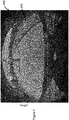
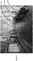
Figure 3 shows an image demonstrating the output of a dense optical flow evaluation of two images taken from a camera mounted on a moving vehicle; -
Figure 4 shows a cell matrix overlaid on an image from a camera module on a vehicle; -
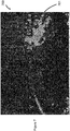
Figure 5 shows a motion likelihood calculation matrix; -
Figure 6 shows an image in which regions corresponding to moving objects are labelled, the labelling has been performed using a motion likelihood calculation; -
Figure 7 shows a filtered motion likelihood calculation matrix; -
Figure 8 shows an image in which regions corresponding to moving objects are labelled, the labelling has been performed using a filtered motion likelihood calculation; -
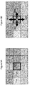
Figure 9A shows part of a cell matrix with the corresponding regions in the horizontal flow information; -
Figure 9B indicates the result of region growing assessments using the data shown infigure 9A ; and -
Figure 10 shows the flow diagram that is followed during the region growing process. - For many tasks involving driving vehicles, acquiring information about moving objects in the local environment is important. For example, it is beneficial to alert a driver if a large object is moving nearby. One way that this can be performed is by analysing images from camera modules mounted on a vehicle.
- The considered vehicle may be self-driving i.e. an autonomous vehicle or have driver assistive features. In this case, the accuracy of the acquired information is particularly important to drive the vehicle or to assist the driver of the vehicle. For example, a vehicle control mechanism may receive information about nearby moving objects and take appropriate action. As an example, a vehicle control mechanism may reduce forward motion of a vehicle if a forward-facing camera mounted on the vehicle shows multiple large moving objections whose trajectory is likely to insect or interfere with that of the vehicle.
- The sensitivity of the cameras used in the invention need not be limited to any specific range of wavelengths but most commonly it will be used with cameras that are sensitive to visible light. The camera will generally be in the form of a camera module comprising a housing for a lens and a sensor, the lens serving to focus light onto the sensor. The camera module may also have electronics to power the sensor and enable communication with the sensor. The camera module may also comprise electronics to process the image. The processing can be low level image signal processing, for example, gain control, exposure control, white balance, denoise, etc. and/or it can involve more powerful processing for example, for computer vision.
- Preferably the camera has a wide field of view to allow moving object detection over a wide angular range. A wide field of view is typically achieved by the camera having a wide field of view lens, such a fisheye lens. A fisheye lens is preferable as these are generally cylindrically symmetric. In some applications of the invention, the field of view may be over 180 degrees. In other applications of the invention, the field of view may be less or more than 180 degrees. Whilst a fisheye lens is preferred, any other lens that provides a wide field of view can be used. In this context, a wide field of view is a lens having a field of view over 100 degrees, preferably over 150 degrees and more preferably over 170 degrees. Typically, cameras with such a wide field of view result in imaging artefacts and distortions in acquired images.
- Turning to
figure 1 , avehicle 1 with acamera 2 is travelling in a first direction, which is indicated by a dotted line D1. The optical axis of the camera is orientated along the first direction D1 i.e. it is a front-facing camera on thevehicle 1. Within thecamera 2 field of view, FOV, are two objects. A first object 3 travelling in a second direction D2 of travel that is different to the first direction, and asecond object 4 which is not moving i.e. static. At a first time, thecamera 2 has a first pose C1. Due to the motion of thevehicle 2, at a later time, thecamera 2 has a second camera pose C2. The difference between C2 and C1 is a first camera pose change. If the camera pose is subsequently changed there will be a second camera pose change moving the camera to a third pose. - A first image and a second image are acquired from the
camera 2. The first and second image have the same size and resolution. In other embodiments, image processing can be used to ensure that acquired images of different size and/or resolution are converted to images of the same size and resolution. - If the first image is acquired from the
camera 2 at the first pose C1 and the second image is acquired at the second pose C2, the position of the bothobjects 3, 4 will have changed relative to thecamera 2. The difference of thesecond object 4 in the images will be entirely due to the motion of thevehicle 1. However, the difference of the first object 3 in the images is partly due to the motion D2 of the object 3 and partly due to the motion D1 of thevehicle 1. - Data from sensors 5 on the
vehicle 1 can be processed to ascertain the vehicle motion, from which the first camera pose change can be measured. In some embodiments, the sensors 5 will be one or more odometers that are rigidly mounted on the vehicle. However, any sensor that allows the change in camera pose to be determined can be used to work the invention. Given the first image and the second image and the sensor data, the process summarized infigure 2 can be followed to identify and report moving objects. - Turning to the first step in
figure 2 , the first image and the second image are processed 100 to evaluate the difference between the first image and the second image. This processing is performed using known techniques such as dense optical flow, DOF, which is described in G. Farneback's article titled " Two-frame motion estimation based on polynomial expansion" in Scandinavian conference on Image analysis, Springer, 2003, p363-370. The result of using DOF to assess the difference between the first image and the second image is a dense optical flow image, which comprises an image of vectors that define the flow information or flow map. The image is preferably the same size as the first image. The flow information comprises a series of horizontal and vertical flow vectors that indicate the difference in the position of pixels between the first image and the second image. - The flow information can be displayed in various ways. One way is to make an image in which a plurality of arrows overlay the first image. The direction and size/length of the arrows may then indicate the difference, or flow, between the images. An example of such an image is shown in
figure 3 . - DOF assessment characterizes the change in location of pixel regions from the first image in the second image. The size of the pixel regions is configurable. Solely as an example, pixel regions may be sized as a square of 9 pixels (3x3). Often considered pixel regions will have few or no unique identifying features and/or images may have repeating structures. Consequently, the resultant flow information may have a lot of noise and may comprise areas where invalid, or no, flow information has been evaluated. An example of this is shown in
figure 3 in which a region has been circled with several arrows that appear to point downwards in a region of the flow information that comprises arrows that are aligned in a substantially leftward direction. These incoherent arrows, likely arising due to the repeating pattern on the wall, represent erroneous flow information due to mistakes in the DOF assessment. - Referring to
Figure 4 , when assessing motion and attempting to detect moving objects, it is more important to have reliable flow information that can be processed quickly than to have single pixel precision object detection. For this reason, it is preferable to aggregate the flow information into cells. The cells are arranged in a two-dimensional array called acell matrix 400 an example of which along with anexemplary cell 401 are shown in theFigure 4 . Thecell matrix 400 is a rectangular image of flow information. Thecell matrix 400 is sized to minimize areas of the camera images that do not contain flow information. In other embodiments, different shapes of cell matrix can be used. - In
Figure 4 , the housing of the vehicle and camera, which will not change significantly between acquired images has mostly been cropped away by appropriate selection of the width and height of thecell matrix 400. The cell size is application specific but selecting cells sized as a square of 25 pixels (5x5) of the first image is typical. In this case, each cell of thecell matrix 400 will comprise an aggregated form of the flow information from a region covering 25 pixels. Thecell matrix 400 is formed using the result of the DOF assessment. Thus, the shape of the cell in thecell matrix 400 can be set regardless of the shape of the pixel region size used in the DOF assessment. - Forming the
cell matrix 400 is similar to binning or aggregating, the flow information. Such aggregation reduces the resolution of the DOF assessment to the cell size but greatly improves the future processing speed and results in lower noise and fewer cells having invalid flow information. The specific calculation used when aggregating can vary. Any calculation may be used if it processes the flow information to produce at least one value of flow information for a cell that is reflective of all the flow information in the region of the flow information corresponding to the cell. - Typically, the values of the horizontal and vertical flow information in each cell are calculated as the mean of the valid flow vector components in the region of the flow information corresponding to the cell. In this way, even if not all the considered flow information values are valid, it is still possible to assign a value to the cell and thereby fill small regions of invalid flow information. If the cell comprises no valid flow information (e.g. all values are zero), the cell is set to invalid. When this
step 110 is complete, thecell matrix 400 is said to be formed. - The
next step 120 ofFigure 3 takes sensor information that reveals the difference in camera pose between acquired images. As examples, odometry from a camera sensor or odometry information obtained from a sensor 5 mounted on the vehicle can be used. The sensor information is processed to obtain the difference in camera pose. The camera pose and thecell matrix 400 are then passed to a motion likelihood calculation module, and a motion likelihood calculation is performed 120. The output of this calculation is amotion likelihood matrix 500, such as shown infigure 5 . In the embodiment, themotion likelihood matrix 500 has the same dimensions as the cell matrix. Eachcell 501 of themotion likelihood matrix 500 displays calculated motion information which indicates the likelihood of motion on a scale from 0 to 1. Infigure 5 , the illustrated data runs from black (0) to white (1). Of course, the illustrated scale and data is only exemplary to demonstrate the method. - Preferably the motion likelihood calculation is calculated on a cellular matrix to produce a motion likelihood matrix in the manner described in the article " Spherical formulation of moving object geometric constraints for monocular fisheye cameras" published by L. Mariotti and C. Hughers for the 2019 IEEE Intelligent Transportation Systems Conference. The resultant motion likelihood matrix is a map of the motion likelihood i.e. an image of motion likelihood.
- Using the
motion likelihood matrix 500, regions of motion can be labelled as moving objects. However, such labelling produces noisy results with apparent errors.Figure 6 demonstrates this, by showing the result of labelling themotion likelihood matrix 500 offigure 5 to indicate regions of motion. Infigure 6 , three movingregions figure 6 , that all three moving regions correspond to parts of the same vehicle. Therefore, only one single moving region representing the vehicle should have been labelled. - Such errors are common because the flow information from the DOF assessment, and consequently the
cell matrix 400 andmotion likelihood matrix 500, is noisy. Noise in the flow information arises because the pixel searching that DOF assessment involves is challenging. The difficulty increases for images having: fractal parts, such as clouds; homogeneous areas without distinguishing features to match; and repeated patterns (e.g. fences, gates, bricks etc). Mismatches or failure to match are common. - When mismatches occur, the flow information produced by the DOF assessment can often be determined by visual analysis to be wrong, as the erroneous flow information often has a surprising orientation relative to the surrounding flow information (see
figure 3 ). Erroneous flow information due to mismatching may also produce large values in the flow information and large value in the motion likelihood metric. - Mismatches are a common source of false positives in moving object detection. However, simple analysis of flow information cannot distinguish whether an area with notably different values to surrounding flow information is due to a moving object (a valid moving object) or a mistake in the DOF assessment (a false positive due to a mismatch). The present invention uses two different approaches to help address this problem: temporal filtering and spatial filtering.
- Temporal filtering, or filtering over time, will be described first. Certain features e.g. clouds in the sky lead to noise in flow information. This presents as a random variation in the
motion likelihood matrix 500. As it is a random variation, by comparing two motion likelihood matrices generated from successive images and using the lowest values in corresponding cells of the motion likelihood matrices, the random variation will be suppressed. A minimum operator takes values and returns the lowest. Consequently, applying a minimum operator to multiple motion likelihood matrices reduces the incidence of noise in the resultant motion likelihood matrix produced by the operation. - Considering two successive motion likelihood matrices (e.g. a current
motion likelihood matrix 500 and a previous motion likelihood matrix), the minimum value between two cells at the same position will be taken. If one cell in the compared cells has no valid value, the value in the valid cell is used. If both cells have invalid data, an invalid result is recorded. Temporal filtering improves the completeness of the resultant motion likelihood matrix as it fills in regions with invalid flow in the processed motion likelihood matrices, which are frequent in the case of large and homogeneous regions in the camera images. - By applying the minimum operator to increasing numbers of motion likelihood matrices, noise can be effectively suppressed. The downside of temporal filtering is that the values of the cells representing small moving objects may also be reduced (e.g. moving objects in the far distance may be suppressed rather than labelled). However, for most vehicular applications, it is more important to accurately label a large nearby moving object than to ensure all moving objects are labelled.
- An example of a filtered
motion likelihood matrix 700 produced by the temporal filtering of two consecutive motion likelihood matrices is shown infigure 7 . This image has been formed from the same image data used to produce the unfilteredmotion likelihood matrix 500 seen infigure 5 . It is clear by comparison offigure 5 andfigure 7 that the filtering has helped to reduce the noise and fill in voids in the motion likelihood matrix. - Given the knowledge that there should be only one single moving region representing a moving vehicle (see the car of the right-hand side of
figure 8 ), it is also clear that the filtering has produced a motion calculation matrix that better represents the motion in the imaged environment - Another filtering method is the method of filtering with a spatial filter using the variance in the flow information for a given image. For each cell, the covariance matrix of the horizontal and vertical flow components in the region of the flow information corresponding to the cell is calculated. The sum of the eigenvalues of the covariance matrix is then used as a measure of dispersion. From the sum of the eigenvalues, the weight applied to each cell of the feature matrix, WDOF, is set as:

motion likelihood matrix 500 has, in each cell, a weight assigned ranging between 0 (high variance meaning a low reliability) and 1 (low variance meaning a high reliability). After weighing the motion likelihood matrix values, a filtered motion likelihood matrix is formed i.e.spatial filtering 130 has been applied. - Effectively, spatial filtering assumes that inconsistent local flow in flow information is likely due to error in the calculation process and not small moving objects. With this approach, the influence of random-like noise (e.g. sky) is also reduced. If the region of erroneous flow information is bigger than the cell size or if the spatial variation is "smooth", the erroneous flow information will not be filtered by the spatial filter as the variance will still be low. Whilst this means the spatial filtering is not perfect, this also ensures that most validly identified motion is not suppressed by spatial filtering.
- The motion likelihood matrix after filtering is considered the final motion likelihood matrix. The final motion likelihood matrix is subsequently processed to identify regions that correspond to moving objects. This is a form of segmentation and is called labelling.
- When labelling, high values in a filtered motion likelihood matrix, preferably above a threshold spatial density, may be used to determine the position and shape of moving objects. In other words, a high concentration of motion likelihood values provides an initial estimate of a region that is a moving object. Such value and spatial density thresholding provides an initial labelling.
- Typically, motion likelihood calculations use the ground plane as reference in the calculation and are consequently less effective below the horizon. This means that the initial labelling may be inaccurate above the horizon. To improve the accuracy of the labelling, a region growing process is used. The growing is performed using the flow information in the
cell matrix 400. Since thecell matrix 400 is the same size and shape as themotion likelihood matrix 500 the information from both images can be used together when region growing. To start, the cells with positive values in the final motion likelihood matrix mark the seed regions. In other embodiments, the seeds may be set by other known methods e.g. random assignment or estimating regions by machine learning methods. - Every seed has a region label assigned and, preferably, each seed has a unique region label. For each seed, the associated region expands, or grows, according to the similarity in the corresponding regions of the
cell matrix 400. In other words, the region growing is performed on the cell matrix 400 (the flow information) but the seeds are set using the results from the motion likelihood matrix 500 (the motion likelihood). - For each region label, adjacent cells to every cell with the region label in the cell matrix are identified and marked with the region label if the difference with the adjacent cells satisfies growing criteria. The process repeats until the number of cells with the region label does not increase or until a maximum number of iterations has been reached. The region growing algorithm is based on a flood filing principle over 4 connected neighbours (the adjacent cells in the upward, leftward, downward, and rightward direction in the cell matrix) but uses bespoke criteria and multiple threshold to avoid instabilities and improve performance in the considered context. During region growing, if two regions become adjacent to each other they merge into one region.
- The growing criteria is that a considered cell has no other region label assigned; has a valid value i.e. the flow information exists and is not zero; has a value bigger than a growing threshold; and has a value that satisfies similarity criteria with other cells. The use of a growing threshold avoid instability due to comparison of small numbers.
- The use of similarity criteria helps ensure that the region (all cells labelled with a region number) expands only to include the cells that belong to the candidate object e.g. the moving object. The similarity criteria comprise both local level and global level similarity criteria. In other embodiments, only one of the local level and global level similarity criteria may be used.
- The global level similarity criteria requires that the difference between the cell value of a considered cell and the mean value of all cells presently labelled in the same region label is below a region-similarity threshold. As with all region growing thresholds, the region-similarity threshold is configurable. The region-similarity threshold may also be adaptive and may depend on the specific parameters in the acquired images e.g. noise.
- The local level similarity criteria relate to comparisons with adjacent cells in the upward, leftward, downward, and rightward direction i.e. the 4 connected neighbouring cells. The specific criteria are different in different directions. A first local criterion is that, in the upward direction, the difference must be below a first local threshold. A second local criterion is that, in the left-right direction, the difference must be below the first local threshold and below the difference in the opposite direction by a second local threshold. A third local criterion is that, in the downward direction, the difference must be positive and below the first local threshold.
- The second and third local criterion avoids the growing region expanding into cells that correspond with a road surface in the acquired images. The second local criterion promotes the growth on the most homogeneous direction according to the flow information. The third local criterion works on the assumption that the flow right below an object is smaller in magnitude that the flow of the moving object.
- For improved speed/efficiency, the comparison of the flow information during region growing is performed only on the horizontal flow information. This assumes that object motion will be mostly be in a plane which is parallel to the direction of change in camera pose. For many applications, such as a front-facing camera on a vehicle on a road this is a reasonable assumption, given it is likely other objects will be moving on the same road as the vehicle.
- The local level similarity criteria are particularly relevant for the case of an object with a direction of motion towards a forward moving camera. This is because in this case the direction of the flow information at the moving object is the same as other static parts of the surrounding environment (as the other parts are also approaching the camera as it moves forward), only the magnitude of flow information is different.
- In situations where the direction of the object is the opposite, e.g. for an object that is moving away from the moving camera, the relative difference with the mean flow of the region will likely already be enough to block the growth of the region.
-
Figures 9A and 9B provide an examples of cell assessment that may occur during the region growing process. InFigure 9A , the magnitude of the horizontal flow information is indicated both by the darkness of the cell and the length of the arrow in the cell. Theseed cell 900 is marked by a black rectangle in bothfigures (9A and 9B ). -
Figure 9B demonstrates whether the region growing criteria are met in the four directions of the 4-connected cells (upwards - toward theupper cell 901, leftward - toward theleftward cell 902, downward - toward thelower cell 903, and rightward - toward the rightward cell 904). Infigure 9B , white arrows indicate the growing criteria in the direction of the arrow are satisfied and black arrows indicate the growing criteria in the direction of the arrow are not satisfied. - Growth in the upward region, growing the region of the seed into
upper cell 901, is allowed as the flow information are in the same direction and above the growing threshold. Growth in the downward region is blocked because, even through thelower cell 903 has flow information directed similarly to theseed cell 900 and is above the growing threshold, the difference between theseed cell 900 and thelower cell 903 is negative. In the left-right direction, the leftward and rightward cell have both flow information directed similarly to theseed cell 900 and above the growing threshold, however the difference between theseed cell 900 and theleftward cell 904 is bigger than the difference between theseed cell 900 and therightward cell 902 so the growth is only permitted in the rightward direction. - The growing process is further detailed in
figure 10 , which provides a flow chart of the region growing process and lists the criteria assessed on the horizontal flow in the cell matrix. - The region growing process improves the accuracy of the region labelling. In other words, the final region indicating the moving objection is more accurately aligned to the moving object in the acquired images from the camera.
- After processing the filtered
motion likelihood image 700 by region growing the result is a single movingregion 801, as shown by the bounding polygon overlaid the camera image offigure 8 . Thisregion 801 is in good alignment with the moving car seen in the underlying camera image on the right-hand side. - It is therefore more likely that by following the above-described process, more regions corresponding to moving objects will be identified. The resultant information can then be reported to the driver and/or a vehicular module. As described above, the method may be used in a vehicular module such as a vehicle control mechanism. In this case, the vehicle control mechanism will take the information into account when controlling the vehicle.
- The information may also be reported or recorded. Reporting or recording may be in the form of an audio alert, a record in a storage device e.g. a hard disk, or a display on a screen that is visible to the driver. As shown in
figure 8 , a useful way of reporting the information is to display an image from a camera with the identified moving objects encased in polygons.
Claims (15)
- A method for identifying moving objects in an imaged environment comprising:acquiring a first camera image, from a camera (2) mounted on a vehicle (1), at a first time at a first pose (C1);acquiring a second camera image, from the camera (2), at a second pose (C2) at a second time, the second time being after the first time;acquiring a third camera image, from the camera (2), at a third pose at a third time, the third time being after the second time;forming (100) a first optical flow map from the first camera image and the second camera image;forming a second optical flow map from the second camera image and the third camera image;forming a motion likelihood image for said third camera image in which a value for each motion likelihood image location is formed by:selecting a plurality of flow information values from a region of the second flow map corresponding to said location;aggregating the plurality of flow information values and, using a pose change between said second and third poses, forming a motion likelihood value for said location;weighting (130) the motion likelihood value according to the variance of the plurality of flow information values in said region; andselecting a minimum (140) of the motion likelihood value and a corresponding motion likelihood value previously formed from the first optical flow map; andidentifying (150) regions of the motion likelihood image as corresponding to moving objects.
- The method of claim 1, wherein weighting the motion likelihood value according to the variance of the plurality of flow information values in said region, comprises:calculating a covariance matrix for horizontal and vertical flow values in the plurality of flow information values;summing the eigenvalues of the covariance matrix into a summed value, λ; andmultiplying the motion likelihood value by 1/(1 + ωλ2), where ω is an adjustable parameter.
- The method of claim 1 or 2, wherein the pose change is determined from data from a vehicle mounted odometry sensor.
- The method of any preceding claim, wherein selecting a minimum of the motion likelihood value and a corresponding motion likelihood value previously formed from the first optical flow map forms a minimum likelihood value; and weighting the motion likelihood value comprises weighting the minimum motion likelihood value.
- The method of any of claims 1 to 3, wherein selecting a minimum of the motion likelihood value and a corresponding motion likelihood value comprises:
selecting a minimum of the weighted motion likelihood value and a corresponding weighted motion likelihood value. - The method of any preceding claim, wherein selecting a minimum of the motion likelihood value and a corresponding motion likelihood value comprises:
if only one of the motion likelihood values is valid, selecting the valid motion likelihood value. - The method of any preceding claim, wherein the camera comprises a fisheye lens.
- The method of any preceding claim, wherein identifying regions of the motion likelihood image as corresponding to moving objects comprises:labelling values (150) in the motion likelihood image above a threshold as corresponding to moving objects; andreporting (160) the labelled values.
- The method of claim 8, wherein horizontal flow values in the second optical flow map are aggregated into a two-dimensional array, and
wherein labelling values (150) in the motion likelihood image above a threshold as corresponding to moving objects comprises:identifying positions in the motion likelihood image with a value above a threshold as a seed location;for each position in the array at a seed location, labelling the array position with a region number; andgrowing the regions by, repeatedly:identifying array positions that are adjacent to an array position with the region label; andlabelling each array position of the identified array positions with the region label if the horizontal flow value at the array position satisfies certain conditions. - The method of claim 9, wherein growing the regions repeats until a maximum number of iterations is reached or until the number of array positions labelled with the region label does not increase in an iteration.
- The method of claim 9 or 10, wherein the certain conditions are that the considered array position:has no other region label assigned;has a valid horizontal flow value;has a horizontal flow value greater than a growing threshold; andhas a horizontal flow value that satisfies similarity criteria with horizontal flow values at other array positions.
- The method of claim 11, wherein the similarity criteria comprise the criterion of the difference, in horizontal flow, being within a region-similarity threshold with the mean value of all horizontal flow values at array positions labelled with the same region label as the considered array position.
- The method of claim 11 or 12, wherein the similarity criteria comprise the criteria of the differences, in horizontal flow values, between a considered array position and adjacent array position being:in the upward direction, below a first local threshold;in the left-right direction, below the first local threshold and below the difference in the opposite direction by a second local threshold; andin the downward direction, positive and below the first local threshold.
- A vehicle comprising a camera module, the camera module operating according to any preceding method.
- The vehicle of claim 14, further comprising a vehicle control mechanism configured to receive a report of the identified regions of the motion likelihood image corresponding to moving objects and to take this information into account when controlling the vehicle.
Applications Claiming Priority (1)
| Application Number | Priority Date | Filing Date | Title |
|---|---|---|---|
| DE102020101444.9A DE102020101444A1 (en) | 2020-01-22 | 2020-01-22 | A method of detecting moving objects |
Publications (2)
| Publication Number | Publication Date |
|---|---|
| EP3855393A1 true EP3855393A1 (en) | 2021-07-28 |
| EP3855393B1 EP3855393B1 (en) | 2022-07-20 |
Family
ID=74194647
Family Applications (1)
| Application Number | Title | Priority Date | Filing Date |
|---|---|---|---|
| EP21152677.7A Active EP3855393B1 (en) | 2020-01-22 | 2021-01-21 | A method for detecting moving objects |
Country Status (2)
| Country | Link |
|---|---|
| EP (1) | EP3855393B1 (en) |
| DE (1) | DE102020101444A1 (en) |
Cited By (1)
| Publication number | Priority date | Publication date | Assignee | Title |
|---|---|---|---|---|
| CN116740147A (en) * | 2023-06-21 | 2023-09-12 | 中科智云科技有限公司 | A target search method, device, equipment and medium |
Families Citing this family (1)
| Publication number | Priority date | Publication date | Assignee | Title |
|---|---|---|---|---|
| DE102020112204A1 (en) | 2020-05-06 | 2021-11-11 | Connaught Electronics Ltd. | System and method for controlling a camera |
Citations (1)
| Publication number | Priority date | Publication date | Assignee | Title |
|---|---|---|---|---|
| US20190164296A1 (en) * | 2017-11-27 | 2019-05-30 | Qualcomm Incorporated | Systems and methods for determining a confidence measure for a motion vector |
Family Cites Families (1)
| Publication number | Priority date | Publication date | Assignee | Title |
|---|---|---|---|---|
| DE102017112333A1 (en) | 2017-06-06 | 2018-12-06 | Connaught Electronics Ltd. | Improvement of a pyramidal optical flow tracker |
-
2020
- 2020-01-22 DE DE102020101444.9A patent/DE102020101444A1/en not_active Withdrawn
-
2021
- 2021-01-21 EP EP21152677.7A patent/EP3855393B1/en active Active
Patent Citations (1)
| Publication number | Priority date | Publication date | Assignee | Title |
|---|---|---|---|---|
| US20190164296A1 (en) * | 2017-11-27 | 2019-05-30 | Qualcomm Incorporated | Systems and methods for determining a confidence measure for a motion vector |
Non-Patent Citations (8)
| Title |
|---|
| "IEEE Intelligent Transportation Systems Conference", 2019, L. MARIOTTI AND C. HUGHERS, article "Spherical formulation of moving object geometric constraints for monocular fisheye cameras" |
| A. M. PINTO ET AL.: "Unsupervised flow-based motion analysis for an autonomous moving system", IMAGE AND VISION COMPUTING, vol. 32, no. 6-7, 2014, pages 391, XP029023762, DOI: 10.1016/j.imavis.2014.04.003 |
| A. M. PINTO ET AL.: "Visual motion perception for mobile robots through dense optical flow fields''", ROBOTICS AND AUTONOMOUS SYSTEMS, vol. 87, 2017, pages 1 |
| F. MARTINEZ ET AL.: "A motion descriptor based on statistics of optical flow orientations for action classification in video-surveillance", MULTIMEDIA AND SIGNAL PROCESSING, 2012, pages 267 |
| G. FARNEBACK'S: "Scandinavian conference on Image analysis", 2003, SPRINGER, article "Two-frame motion estimation based on polynomial expansion", pages: 363 - 370 |
| M. NARAYANA ET AL.: "coherent motion segmentation in moving camera videos using optical flow orientations", PROCEEDINGS OF THE IEEE INTERNATIONAL CONFERENCE ON COMPUTER VISION, 2013, pages 1577, XP032572954, DOI: 10.1109/ICCV.2013.199 |
| MARIOTTI LETIZIA ET AL: "Spherical formulation of moving object geometric constraints for monocular fisheye cameras", 2019 IEEE INTELLIGENT TRANSPORTATION SYSTEMS CONFERENCE (ITSC), IEEE, 27 October 2019 (2019-10-27), pages 816 - 823, XP033668878, DOI: 10.1109/ITSC.2019.8917512 * |
| ZHOU DINGFU ET AL: "Moving object detection and segmentation in urban environments from a moving platform", IMAGE AND VISION COMPUTING, vol. 68, 1 December 2017 (2017-12-01), GUILDFORD, GB, pages 76 - 87, XP055808763, ISSN: 0262-8856, DOI: 10.1016/j.imavis.2017.07.006 * |
Cited By (1)
| Publication number | Priority date | Publication date | Assignee | Title |
|---|---|---|---|---|
| CN116740147A (en) * | 2023-06-21 | 2023-09-12 | 中科智云科技有限公司 | A target search method, device, equipment and medium |
Also Published As
| Publication number | Publication date |
|---|---|
| EP3855393B1 (en) | 2022-07-20 |
| DE102020101444A1 (en) | 2021-07-22 |
Similar Documents
| Publication | Publication Date | Title |
|---|---|---|
| CN111563415B (en) | Binocular vision-based three-dimensional target detection system and method | |
| EP3517997B1 (en) | Method and system for detecting obstacles by autonomous vehicles in real-time | |
| CN112950725B (en) | A monitoring camera parameter calibration method and device | |
| US7062071B2 (en) | Apparatus, program and method for detecting both stationary objects and moving objects in an image using optical flow | |
| KR101787542B1 (en) | Estimation system and method of slope stability using 3d model and soil classification | |
| US20020118874A1 (en) | Apparatus and method for taking dimensions of 3D object | |
| US20190065824A1 (en) | Spatial data analysis | |
| CN114359714B (en) | Unmanned human obstacle avoidance method, device and intelligent unmanned human based on event camera | |
| KR102229220B1 (en) | Method and device for merging object detection information detected by each of object detectors corresponding to each camera nearby for the purpose of collaborative driving by using v2x-enabled applications, sensor fusion via multiple vehicles | |
| El Bouazzaoui et al. | Enhancing RGB-D SLAM performances considering sensor specifications for indoor localization | |
| CN111738071B (en) | A method of inverse perspective transformation based on motion changes of monocular camera | |
| CN111738032A (en) | Vehicle driving information determination method and device and vehicle-mounted terminal | |
| JP2026502481A (en) | Parking position detection method and system | |
| EP3855393B1 (en) | A method for detecting moving objects | |
| EP4524905B1 (en) | Method for determining whether contamination exists on camera lens in real-time and computing device using the same | |
| CN113674361B (en) | Vehicle-mounted all-round-looking calibration implementation method and system | |
| Valente et al. | Fusing laser scanner and stereo camera in evidential grid maps | |
| Barua et al. | An efficient method of lane detection and tracking for highway safety | |
| US12530799B2 (en) | System and method for extrinsic parameter calibration and self-inspection of on-vehicle cameras | |
| CN115546784B (en) | 3D target detection method based on deep learning | |
| CN118314179A (en) | Error-time-actual detection method, device and equipment on AI binocular stitching camera | |
| CN117606500A (en) | Deceleration strip detection method, deceleration strip passing method, network training method and related device | |
| JP2020077297A (en) | Position and posture estimation device | |
| WO2022133986A1 (en) | Accuracy estimation method and system | |
| Arain et al. | Close-proximity underwater terrain mapping using learning-based coarse range estimation |
Legal Events
| Date | Code | Title | Description |
|---|---|---|---|
| PUAI | Public reference made under article 153(3) epc to a published international application that has entered the european phase |
Free format text: ORIGINAL CODE: 0009012 |
|
| STAA | Information on the status of an ep patent application or granted ep patent |
Free format text: STATUS: THE APPLICATION HAS BEEN PUBLISHED |
|
| AK | Designated contracting states |
Kind code of ref document: A1 Designated state(s): AL AT BE BG CH CY CZ DE DK EE ES FI FR GB GR HR HU IE IS IT LI LT LU LV MC MK MT NL NO PL PT RO RS SE SI SK SM TR |
|
| STAA | Information on the status of an ep patent application or granted ep patent |
Free format text: STATUS: REQUEST FOR EXAMINATION WAS MADE |
|
| GRAP | Despatch of communication of intention to grant a patent |
Free format text: ORIGINAL CODE: EPIDOSNIGR1 |
|
| STAA | Information on the status of an ep patent application or granted ep patent |
Free format text: STATUS: GRANT OF PATENT IS INTENDED |
|
| 17P | Request for examination filed |
Effective date: 20220128 |
|
| RBV | Designated contracting states (corrected) |
Designated state(s): AL AT BE BG CH CY CZ DE DK EE ES FI FR GB GR HR HU IE IS IT LI LT LU LV MC MK MT NL NO PL PT RO RS SE SI SK SM TR |
|
| RIC1 | Information provided on ipc code assigned before grant |
Ipc: H04N 19/543 20140101ALI20220207BHEP Ipc: G06T 7/11 20170101ALI20220207BHEP Ipc: G06T 7/215 20170101AFI20220207BHEP |
|
| INTG | Intention to grant announced |
Effective date: 20220222 |
|
| GRAS | Grant fee paid |
Free format text: ORIGINAL CODE: EPIDOSNIGR3 |
|
| GRAA | (expected) grant |
Free format text: ORIGINAL CODE: 0009210 |
|
| STAA | Information on the status of an ep patent application or granted ep patent |
Free format text: STATUS: THE PATENT HAS BEEN GRANTED |
|
| AK | Designated contracting states |
Kind code of ref document: B1 Designated state(s): AL AT BE BG CH CY CZ DE DK EE ES FI FR GB GR HR HU IE IS IT LI LT LU LV MC MK MT NL NO PL PT RO RS SE SI SK SM TR |
|
| REG | Reference to a national code |
Ref country code: CH Ref legal event code: EP |
|
| REG | Reference to a national code |
Ref country code: DE Ref legal event code: R096 Ref document number: 602021000215 Country of ref document: DE |
|
| REG | Reference to a national code |
Ref country code: AT Ref legal event code: REF Ref document number: 1506025 Country of ref document: AT Kind code of ref document: T Effective date: 20220815 |
|
| REG | Reference to a national code |
Ref country code: IE Ref legal event code: FG4D |
|
| REG | Reference to a national code |
Ref country code: LT Ref legal event code: MG9D |
|
| REG | Reference to a national code |
Ref country code: NL Ref legal event code: MP Effective date: 20220720 |
|
| PG25 | Lapsed in a contracting state [announced via postgrant information from national office to epo] |
Ref country code: SE Free format text: LAPSE BECAUSE OF FAILURE TO SUBMIT A TRANSLATION OF THE DESCRIPTION OR TO PAY THE FEE WITHIN THE PRESCRIBED TIME-LIMIT Effective date: 20220720 Ref country code: RS Free format text: LAPSE BECAUSE OF FAILURE TO SUBMIT A TRANSLATION OF THE DESCRIPTION OR TO PAY THE FEE WITHIN THE PRESCRIBED TIME-LIMIT Effective date: 20220720 Ref country code: PT Free format text: LAPSE BECAUSE OF FAILURE TO SUBMIT A TRANSLATION OF THE DESCRIPTION OR TO PAY THE FEE WITHIN THE PRESCRIBED TIME-LIMIT Effective date: 20221121 Ref country code: NO Free format text: LAPSE BECAUSE OF FAILURE TO SUBMIT A TRANSLATION OF THE DESCRIPTION OR TO PAY THE FEE WITHIN THE PRESCRIBED TIME-LIMIT Effective date: 20221020 Ref country code: NL Free format text: LAPSE BECAUSE OF FAILURE TO SUBMIT A TRANSLATION OF THE DESCRIPTION OR TO PAY THE FEE WITHIN THE PRESCRIBED TIME-LIMIT Effective date: 20220720 Ref country code: LV Free format text: LAPSE BECAUSE OF FAILURE TO SUBMIT A TRANSLATION OF THE DESCRIPTION OR TO PAY THE FEE WITHIN THE PRESCRIBED TIME-LIMIT Effective date: 20220720 Ref country code: LT Free format text: LAPSE BECAUSE OF FAILURE TO SUBMIT A TRANSLATION OF THE DESCRIPTION OR TO PAY THE FEE WITHIN THE PRESCRIBED TIME-LIMIT Effective date: 20220720 Ref country code: FI Free format text: LAPSE BECAUSE OF FAILURE TO SUBMIT A TRANSLATION OF THE DESCRIPTION OR TO PAY THE FEE WITHIN THE PRESCRIBED TIME-LIMIT Effective date: 20220720 Ref country code: ES Free format text: LAPSE BECAUSE OF FAILURE TO SUBMIT A TRANSLATION OF THE DESCRIPTION OR TO PAY THE FEE WITHIN THE PRESCRIBED TIME-LIMIT Effective date: 20220720 |
|
| REG | Reference to a national code |
Ref country code: AT Ref legal event code: MK05 Ref document number: 1506025 Country of ref document: AT Kind code of ref document: T Effective date: 20220720 |
|
| PG25 | Lapsed in a contracting state [announced via postgrant information from national office to epo] |
Ref country code: PL Free format text: LAPSE BECAUSE OF FAILURE TO SUBMIT A TRANSLATION OF THE DESCRIPTION OR TO PAY THE FEE WITHIN THE PRESCRIBED TIME-LIMIT Effective date: 20220720 Ref country code: IS Free format text: LAPSE BECAUSE OF FAILURE TO SUBMIT A TRANSLATION OF THE DESCRIPTION OR TO PAY THE FEE WITHIN THE PRESCRIBED TIME-LIMIT Effective date: 20221120 Ref country code: HR Free format text: LAPSE BECAUSE OF FAILURE TO SUBMIT A TRANSLATION OF THE DESCRIPTION OR TO PAY THE FEE WITHIN THE PRESCRIBED TIME-LIMIT Effective date: 20220720 Ref country code: GR Free format text: LAPSE BECAUSE OF FAILURE TO SUBMIT A TRANSLATION OF THE DESCRIPTION OR TO PAY THE FEE WITHIN THE PRESCRIBED TIME-LIMIT Effective date: 20221021 |
|
| REG | Reference to a national code |
Ref country code: DE Ref legal event code: R097 Ref document number: 602021000215 Country of ref document: DE |
|
| PG25 | Lapsed in a contracting state [announced via postgrant information from national office to epo] |
Ref country code: SM Free format text: LAPSE BECAUSE OF FAILURE TO SUBMIT A TRANSLATION OF THE DESCRIPTION OR TO PAY THE FEE WITHIN THE PRESCRIBED TIME-LIMIT Effective date: 20220720 Ref country code: RO Free format text: LAPSE BECAUSE OF FAILURE TO SUBMIT A TRANSLATION OF THE DESCRIPTION OR TO PAY THE FEE WITHIN THE PRESCRIBED TIME-LIMIT Effective date: 20220720 Ref country code: DK Free format text: LAPSE BECAUSE OF FAILURE TO SUBMIT A TRANSLATION OF THE DESCRIPTION OR TO PAY THE FEE WITHIN THE PRESCRIBED TIME-LIMIT Effective date: 20220720 Ref country code: CZ Free format text: LAPSE BECAUSE OF FAILURE TO SUBMIT A TRANSLATION OF THE DESCRIPTION OR TO PAY THE FEE WITHIN THE PRESCRIBED TIME-LIMIT Effective date: 20220720 Ref country code: AT Free format text: LAPSE BECAUSE OF FAILURE TO SUBMIT A TRANSLATION OF THE DESCRIPTION OR TO PAY THE FEE WITHIN THE PRESCRIBED TIME-LIMIT Effective date: 20220720 |
|
| PLBE | No opposition filed within time limit |
Free format text: ORIGINAL CODE: 0009261 |
|
| STAA | Information on the status of an ep patent application or granted ep patent |
Free format text: STATUS: NO OPPOSITION FILED WITHIN TIME LIMIT |
|
| PG25 | Lapsed in a contracting state [announced via postgrant information from national office to epo] |
Ref country code: SK Free format text: LAPSE BECAUSE OF FAILURE TO SUBMIT A TRANSLATION OF THE DESCRIPTION OR TO PAY THE FEE WITHIN THE PRESCRIBED TIME-LIMIT Effective date: 20220720 Ref country code: EE Free format text: LAPSE BECAUSE OF FAILURE TO SUBMIT A TRANSLATION OF THE DESCRIPTION OR TO PAY THE FEE WITHIN THE PRESCRIBED TIME-LIMIT Effective date: 20220720 |
|
| 26N | No opposition filed |
Effective date: 20230421 |
|
| PG25 | Lapsed in a contracting state [announced via postgrant information from national office to epo] |
Ref country code: AL Free format text: LAPSE BECAUSE OF FAILURE TO SUBMIT A TRANSLATION OF THE DESCRIPTION OR TO PAY THE FEE WITHIN THE PRESCRIBED TIME-LIMIT Effective date: 20220720 |
|
| P01 | Opt-out of the competence of the unified patent court (upc) registered |
Effective date: 20230528 |
|
| PG25 | Lapsed in a contracting state [announced via postgrant information from national office to epo] |
Ref country code: SI Free format text: LAPSE BECAUSE OF FAILURE TO SUBMIT A TRANSLATION OF THE DESCRIPTION OR TO PAY THE FEE WITHIN THE PRESCRIBED TIME-LIMIT Effective date: 20220720 |
|
| PG25 | Lapsed in a contracting state [announced via postgrant information from national office to epo] |
Ref country code: LU Free format text: LAPSE BECAUSE OF NON-PAYMENT OF DUE FEES Effective date: 20230121 |
|
| REG | Reference to a national code |
Ref country code: BE Ref legal event code: MM Effective date: 20230131 |
|
| PG25 | Lapsed in a contracting state [announced via postgrant information from national office to epo] |
Ref country code: BE Free format text: LAPSE BECAUSE OF NON-PAYMENT OF DUE FEES Effective date: 20230131 |
|
| PG25 | Lapsed in a contracting state [announced via postgrant information from national office to epo] |
Ref country code: IE Free format text: LAPSE BECAUSE OF NON-PAYMENT OF DUE FEES Effective date: 20230121 |
|
| PG25 | Lapsed in a contracting state [announced via postgrant information from national office to epo] |
Ref country code: IT Free format text: LAPSE BECAUSE OF FAILURE TO SUBMIT A TRANSLATION OF THE DESCRIPTION OR TO PAY THE FEE WITHIN THE PRESCRIBED TIME-LIMIT Effective date: 20220720 |
|
| PG25 | Lapsed in a contracting state [announced via postgrant information from national office to epo] |
Ref country code: MC Free format text: LAPSE BECAUSE OF FAILURE TO SUBMIT A TRANSLATION OF THE DESCRIPTION OR TO PAY THE FEE WITHIN THE PRESCRIBED TIME-LIMIT Effective date: 20220720 |
|
| PG25 | Lapsed in a contracting state [announced via postgrant information from national office to epo] |
Ref country code: MC Free format text: LAPSE BECAUSE OF FAILURE TO SUBMIT A TRANSLATION OF THE DESCRIPTION OR TO PAY THE FEE WITHIN THE PRESCRIBED TIME-LIMIT Effective date: 20220720 |
|
| REG | Reference to a national code |
Ref country code: CH Ref legal event code: PL |
|
| PG25 | Lapsed in a contracting state [announced via postgrant information from national office to epo] |
Ref country code: CH Free format text: LAPSE BECAUSE OF NON-PAYMENT OF DUE FEES Effective date: 20240131 |
|
| PG25 | Lapsed in a contracting state [announced via postgrant information from national office to epo] |
Ref country code: CH Free format text: LAPSE BECAUSE OF NON-PAYMENT OF DUE FEES Effective date: 20240131 |
|
| PG25 | Lapsed in a contracting state [announced via postgrant information from national office to epo] |
Ref country code: BG Free format text: LAPSE BECAUSE OF FAILURE TO SUBMIT A TRANSLATION OF THE DESCRIPTION OR TO PAY THE FEE WITHIN THE PRESCRIBED TIME-LIMIT Effective date: 20220720 |
|
| PG25 | Lapsed in a contracting state [announced via postgrant information from national office to epo] |
Ref country code: BG Free format text: LAPSE BECAUSE OF FAILURE TO SUBMIT A TRANSLATION OF THE DESCRIPTION OR TO PAY THE FEE WITHIN THE PRESCRIBED TIME-LIMIT Effective date: 20220720 |
|
| PG25 | Lapsed in a contracting state [announced via postgrant information from national office to epo] |
Ref country code: CY Free format text: LAPSE BECAUSE OF FAILURE TO SUBMIT A TRANSLATION OF THE DESCRIPTION OR TO PAY THE FEE WITHIN THE PRESCRIBED TIME-LIMIT; INVALID AB INITIO Effective date: 20210121 |
|
| PG25 | Lapsed in a contracting state [announced via postgrant information from national office to epo] |
Ref country code: HU Free format text: LAPSE BECAUSE OF FAILURE TO SUBMIT A TRANSLATION OF THE DESCRIPTION OR TO PAY THE FEE WITHIN THE PRESCRIBED TIME-LIMIT; INVALID AB INITIO Effective date: 20210121 |
|
| PG25 | Lapsed in a contracting state [announced via postgrant information from national office to epo] |
Ref country code: TR Free format text: LAPSE BECAUSE OF FAILURE TO SUBMIT A TRANSLATION OF THE DESCRIPTION OR TO PAY THE FEE WITHIN THE PRESCRIBED TIME-LIMIT Effective date: 20220720 |
|
| PGFP | Annual fee paid to national office [announced via postgrant information from national office to epo] |
Ref country code: GB Payment date: 20260127 Year of fee payment: 6 |
|
| PGFP | Annual fee paid to national office [announced via postgrant information from national office to epo] |
Ref country code: DE Payment date: 20260114 Year of fee payment: 6 |
|
| PGFP | Annual fee paid to national office [announced via postgrant information from national office to epo] |
Ref country code: FR Payment date: 20260128 Year of fee payment: 6 |