EP3855344A1 - Method and device for determining analysis region for lane detection - Google Patents
Method and device for determining analysis region for lane detection Download PDFInfo
- Publication number
- EP3855344A1 EP3855344A1 EP19862778.8A EP19862778A EP3855344A1 EP 3855344 A1 EP3855344 A1 EP 3855344A1 EP 19862778 A EP19862778 A EP 19862778A EP 3855344 A1 EP3855344 A1 EP 3855344A1
- Authority
- EP
- European Patent Office
- Prior art keywords
- coordinate system
- camera
- determining
- lane
- domain
- Prior art date
- Legal status (The legal status is an assumption and is not a legal conclusion. Google has not performed a legal analysis and makes no representation as to the accuracy of the status listed.)
- Granted
Links
Images




Classifications
-
- G—PHYSICS
- G06—COMPUTING OR CALCULATING; COUNTING
- G06V—IMAGE OR VIDEO RECOGNITION OR UNDERSTANDING
- G06V20/00—Scenes; Scene-specific elements
- G06V20/50—Context or environment of the image
- G06V20/56—Context or environment of the image exterior to a vehicle by using sensors mounted on the vehicle
- G06V20/588—Recognition of the road, e.g. of lane markings; Recognition of the vehicle driving pattern in relation to the road
Definitions
- the present disclosure relates to the fields of intelligent transportation and image processing, in particular to a method and device for determining an analysis area in lane detection.
- AD autonomous driving
- ADAS advanced driver assistance system
- the AD/ADAS may be supported by a radar, a visual camera (hereinafter referred to as a camera), a laser radar, an ultrasonic sensor and the like to perform lane detection.
- the camera is most widely used because it can achieve two-dimensional image information as same as human vision.
- the captured image includes various information about the detection object and environment, which is numerous and is not all related to the lane detection. Therefore, in the process of lane detection, if all the information is considered in the image processing, a lot of time consumption and unnecessary calculation will be generated, affecting the detection efficiency.
- an objective of the present disclosure is to provide a method of determining an analysis area in lane detection, so as to solve the problem that image processing in the lane detection is cumbersome.
- a method of determining an analysis area in lane detection includes: performing image processing of a camera image captured by a camera on a vehicle, and the analysis area is an area in the camera image that is confined to perform the image processing, and the method includes: establishing a road coordinate system; establishing a camera coordinate system; determining a relative relation between the road coordinate system and the camera coordinate system, wherein the relative relation includes a lateral shift of the camera relative to a center of the lane and an angle between a vehicle direction and a lane direction, where it is assumed that the vehicle direction and an azimuth angle of the camera are the same; determining a first domain in the camera coordinate system, wherein the first domain requires that the lane be covered when the lateral shift and the angle are present; and converting the first domain to the analysis area in the camera image based on the camera coordinate system.
- determining a relative relation between the road coordinate system and the camera coordinate system comprises: integrating the road coordinate system and the camera coordinate system into the same coordinate system on the basis of a road surface, and obtaining a lateral movement value or a rotation value of the camera coordinate system with respect to the road coordinate system, determining the lateral shift based on the lateral movement value, and determining the angle based on the rotation value.
- determining a first domain in the camera coordinate system comprises: determining the lateral shift and the angle, determining a boundary parameter of the first domain such that the first domain satisfies the determined lateral shift and the determined angle, and constructing the first domain based on the determined boundary parameter.
- determining the lateral shift and the angle comprises: determining the lateral shift is one quarter of the lane width, and the angle-is the half of the vehicle angle against the lane when doing the lane change.
- the first domain is adaptively changeable over time.
- the method of determining the analysis area in the lane detection has the following advantages: the embodiment of the present disclosure achieves theoretical determination of the analysis area to which image processing is applied in lane detection, thereby eliminating calculation and processing on unnecessary image areas, accelerating the lane detection and inhibiting noise in a differential image, thereby realizing more reliable lane detection.
- Another objective of the present disclosure is to provide a machine readable storage medium, and an device for determining an analysis area in lane detection, so as to solve the problem that image processing in the lane detection is cumbersome.
- a machine readable storage medium stores instructions for causing a controller to perform the above method of determining the analysis area in the lane detection.
- An device for determining an analysis area in lane detection includes: performing image processing of a camera image captured by a camera on a vehicle, and the analysis area is an area in the camera image that is confined to perform the image processing, and the device includes: a first coordinate system establishing module, configured to establish a road coordinate system; a second coordinate system establishing module, configured to establish a camera coordinate system; a relative relation determining module, configured to determine a relative relation between the road coordinate system and the camera coordinate system, wherein the relative relation includes a lateral shift of the camera relative to a center of the lane and an angle between a vehicle direction and a lane direction, where it is assumed that the vehicle direction and the azimuth angle of the camera are the same; a domain determining module, configured to determine a first domain in the camera coordinate system, wherein the first domain requires that the lane be covered when the lateral shift and the angle are present; and a domain conversion module, configured to convert the first domain to the analysis area in the camera image based on
- the machine readable storage medium, and the device for determining the analysis area in the lane detection have the same advantages as those of the above method of determining the analysis area in the lane detection compared with the prior art, which will not be elaborated herein.
- the relative relation determining module is configured to determine a relative relation between the road coordinate system and the camera coordinate system comprises: integrating the road coordinate system and the camera coordinate system into the same coordinate on the basis of a road surface, and obtaining a lateral movement value or a rotation value of the camera coordinate system with respect to the road coordinate system, determining the lateral shift based on the lateral movement value, and determining the angle based on the rotation value.
- the domain determining module is configured to determine a first domain in the camera coordinate comprises: determining the lateral shift and the angle, determining a boundary parameter of the first domain such that the first domain satisfies the determined lateral shift and the determined angles, and constructing the first domain based on the determined boundary parameter.
- determining the lateral shift and the angle comprises: determining the lateral shift is one quarter of the lane width, and determining the angle is the half of the vehicle angle against the lane when doing the lane change.
- the machine readable storage medium and the device for determining the analysis area in the lane detection have the same advantages as the above method for determining the analysis area in the lane detection over the prior art, and will not be repeated here.
- An embodiment of the present disclosure provides a method of determining an analysis area in lane detection.
- the definition of the analysis area is described herein with reference to a lane detection process.
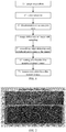
- FIG. 1 is a schematic flowchart of conventional lane detection.
- the conventional lane detection generally includes the following steps: 1) image acquisition; 2) color selection; 3) determination of an analysis area; 4) image difference or image sub-sampling; 5) smoothing, edge detecting (Sobel) and peripheral processing of the image; 6) setting of a threshold to acquire a ternary image; and 7) feature extraction from the ternary image, including edge processing, Hough transformation, lane estimation and the like.
- the image acquisition includes: an image with a lane in front of a vehicle is captured through a camera on the vehicle, wherein the image is referred to herein as a camera image.
- the analysis area determined in the step 3) refers to an area where the image processing involved in the subsequent steps is applied in the camera image. Obviously, determination of the analysis area is beneficial to avoiding unnecessary image pixel calculation, but there is no theoretical solution to determine the analysis area, which is selected by a relative value of the camera image in vertical and horizontal directions.
- FIG. 2 is a schematic diagram of a traditional analysis area, which is an analysis area determined by a ratio of the analysis area in vertical and horizontal directions specified in Table 1 and the camera specifications in Table 2.
- the embodiment of the present disclosure provides the above method of determining the analysis area in the lane detection.
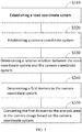
- FIG. 3 is a schematic flowchart of a method of determining an analysis area in lane detection according to an embodiment of the present disclosure.
- the lane detection includes: performing image processing of a camera image captured by a camera on a vehicle, and the analysis area is an area in the camera image that is confined to perform the image processing.
- the method may include the following steps:
- the relative relation includes a lateral shift of the camera relative to the center of the lane and an angle between a vehicle direction and a lane direction.
- the vehicle direction is as same as a direction indicated by the azimuth angle of the camera.
- determine the relative relation includes: integrate the road coordinate system and the camera coordinate system into the same coordinate system on the basis of a road surface, and obtain a lateral movement value or a rotation value of the camera coordinate system with respect to the road coordinate system, determine the lateral shift based on the lateral movement value, and determine the angle based on the rotation value.
- the lateral shift and the angle are the relative relation that needs to be determined and are respectively set as y r and ⁇ r .
- the movement/rotation is essentially the lateral shift of the camera relative to the center of the lane and the angle of the vehicle direction relative to the lane direction (referring to FIG. 6 (c) and FIG. 6 (c) ), that is, the above lateral movement value is the lateral shift and the rotation value is the angle. It should be noted that the longitudinal movement of the two coordinate systems is ignored here.
- the camera position is (0, 0, z camera )
- the direction ( ⁇ c , ⁇ c ) is equal to ( ⁇ c , 0)
- it is assumed that the x axis has little influence
- the camera generates a lateral shift y r relative to the center of the lane
- FIG. 6 (c) relative to FIG. 6 (a) and FIG. 6 (b)
- Step S340 determine a first domain is in the camera coordinate system.
- the first domain requires that the lane be covered when the lateral shift and the angle are present.
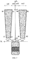
- FIG. 7 is a schematic diagram of a first domain according to an embodiment of the present disclosure.
- z c 0.
- the first domain is determined as two areas which are symmetrical along the x c axis, and each area covers one lane.
- the relative relation of the road coordinate system and the camera coordinate system is changed, as above, that is, the camera coordinate system moves/rotates relative to the road coordinate system based on the lateral shift y r and the angle ⁇ r , and the first domain must ensure that even if the relative relation of the road coordinate system and the camera coordinate system is changed, the lane can be covered.
- FIG. 8 is a schematic diagram of a first domain determined based on a boundary condition in Table 3.
- y r 0
- ⁇ r 0
- a field of view (FOV) of the camera is, for example, 12.2 deg.
- the LW represents the width of the lane
- the parameters in the table such as x1, x2 and wl1 are configured corresponding to the lane width, and the meanings expressed by the parameters may be clearly understood with reference to FIG. 7 , which are not elaborated herein.
- x1 is generally not taken as 0 because the camera is generally mounted at a rearview mirror of the vehicle and the camera cannot see a short driving distance in front of the vehicle due to the visual angle, for example, 10 m. therefore, x1 is, for example, taken as 10 m.
- the determination of the first domain may include: determining the lateral shift and the angle, determining a boundary parameter of the first domain such that the first domain satisfies the determined lateral shift and the determined angle, and constructing the first domain based on the determined boundary parameter.
- the determination of the lateral shift and the angle includes: the lateral shift is determined to be one quarter of the lane width, and the angle is determined to be the half of the vehicle angle against the lane when doing the lane change.
- the lateral shift is determined to be one quarter of the lane width
- the angle is determined to be the half of the vehicle angle against the lane when doing the lane change.
- it may be determined from the current rotating velocity, the lateral velocity, etc. of the vehicle that the half of the vehicle angle against the lane is about 2 deg when doing the lane change, that is, the angle is about 2 deg.
- the lane width is 3.75 m.
- the lateral velocity is about 1.4 m/s at 80 km/h and the corresponding current angle is about 2 deg
- the current angle and the determined angle ⁇ r 2 deg and 1 deg are taken as examples below.
- the conditions required to be met are: the lateral shift of LW/4 and the angle ⁇ r of 1 deg.
- Table 4 shows the boundary condition of two first domain meeting the condition
- FIG. 9 is a schematic diagram of the first domain determined based on the boundary condition in Table 4.
- y r LW/4
- ⁇ r 1 deg
- FOV for example
- Step S350 convert the first domain to the analysis area in the camera image based on the camera coordinate system.
- the coordinates on the camera coordinate system established based on the physical position of the camera may be converted into the coordinates in the corresponding camera image through conversion parameters such as a rotation matrix, a camera internal reference matrix and the like.
- conversion parameters such as a rotation matrix, a camera internal reference matrix and the like.
- FIG. 10 is a schematic diagram of an analysis area in a camera image corresponding to the first domain in FIG. 8 , wherein L1 and L2 are lanes and are covered with a left domain and a right domain respectively.
- the example specifically includes the process of the following parts:
- the ternary image may be acquired by applying a threshold to the DDD(m, n).
- the ternary image may include important information (important differential points) because the ternary image covers the analysis area. Unnecessary points in the equation (1) are eliminated.
- Image processing involved in the step 7) may be defined in the analysis area for processing, and a good lane estimation result may be obtained.
- the first domain in the example may adaptively change over time, for example, the first domain in this measurement may be changed according to the lane position measured last time along with time change. For example, if the vehicle moves rightwards from the lane center, the first domain may be changed to the left to keep the lane in the analysis area. In a similar way, if the vehicle direction inclines to the right, the first domain may be changed to the left side.
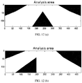
- the analysis area in the finally formed camera image will change correspondingly to ensure the coverage of the lane, as shown in FIG. 12 (a) and FIG. 12 (b).
- FIG. 12 (a) is a schematic diagram of the analysis area when the vehicle is located in the lane center, and the white part in the figure represents the analysis area.
- FIG. 12 (b) is a schematic diagram of the analysis area correspondingly obtained by changing the first domain to the left after the vehicle moves from the lane center to the right, and it can be known that the analysis area is also changed to the left.
- the embodiment of the present disclosure achieves theoretical determination of the analysis area where image processing is applied in lane detection, thereby eliminating calculation and processing on unnecessary image areas, accelerating the lane detection and inhibiting noise in a differential image, thereby realizing more reliable lane detection.
- the speed and the precision of the lane detection can be improved.
- Another embodiment of the present disclosure further provides a machine readable storage medium, wherein the machine readable storage medium stores instructions for causing a controller to perform the method of determining the analysis area in the lane detection described in the above embodiment.
- FIG. 13 is a structural schematic diagram of an device for determining an analysis area in lane detection according to an embodiment of the present disclosure, wherein the lane detection includes: performing image processing of a camera image captured by a camera on a vehicle, and the analysis area is an area in the camera image that is confined to perform the image processing.
- the device includes: a first coordinate system establishing module 110, configured to establish a road coordinate system; a second coordinate system establishing module 120, configured to establish a camera coordinate system; a relative relation determining module 130, configured to determine a relative relation between the road coordinate system and the camera coordinate system, wherein the relative relation includes a lateral shift of the camera relative to a center of the lane and an angle between a vehicle direction and a lane direction; a domain determining module 140, configured to determine a first domain in the camera coordinate system, wherein the first domain requires that the lane be covered when the lateral shift and the angle are present; and a domain conversion module 150, configured to convert the first domain to the analysis area in the camera image based on the camera coordinate system.
- a first coordinate system establishing module 110 configured to establish a road coordinate system
- a second coordinate system establishing module 120 configured to establish a camera coordinate system
- a relative relation determining module 130 configured to determine a relative relation between the road coordinate system and the camera coordinate system, wherein the relative relation includes
- the relative relation determining module 130 is configured to determine the relative relation between the road coordinate system and the camera coordinate system, which may include: integrating the road coordinate system and the camera coordinate system into the same coordinate on the basis of a road surface, and obtaining a lateral movement value or a rotation value of the camera coordinate system with respect to the road coordinate system, determining the lateral shift based on the lateral movement value, and determining the angle based on the rotation value.
- the domain determining module 140 is configured to determine the first domain in the camera coordinate system, which may include: determining the lateral shift and the angle, determining a boundary parameter of the first domain such that the first domain satisfies the determined lateral shift and the determined angles, and constructing the first domain based on the determined boundary parameter. More preferably, the determination of the lateral shift and the angle may include: the lateral shift is determined to be one quarter of the lane width, and the angle is determined to be the half of the vehicle angle against the lane when doing the lane change.
- the program is stored in a storage medium and includes a plurality of instructions for enabling a single chip, a chip or a processor to perform all or some of steps in the method of each embodiment of the present application.
- the foregoing storage medium includes: various medium that may store program codes, such as a USB flash disk, a mobile hard disk, a read-only memory (ROM), a random access memory (RAM), a magnetic disk, or an optical disc.
Landscapes
- Engineering & Computer Science (AREA)
- Physics & Mathematics (AREA)
- General Physics & Mathematics (AREA)
- Multimedia (AREA)
- Theoretical Computer Science (AREA)
- Traffic Control Systems (AREA)
- Image Analysis (AREA)
Abstract
Description
- The present disclosure relates to the fields of intelligent transportation and image processing, in particular to a method and device for determining an analysis area in lane detection.
- At present, vehicles with an autonomous driving (AD) function or advanced driver assistance system (ADAS) have been gradually introduced to the market, thereby greatly promoting the development of intelligent transportation. For the AD/ADAS, lane detection is very important, which is an important condition for the AD/ADAS to perform determination.
- In the prior art, the AD/ADAS may be supported by a radar, a visual camera (hereinafter referred to as a camera), a laser radar, an ultrasonic sensor and the like to perform lane detection. The camera is most widely used because it can achieve two-dimensional image information as same as human vision. However, when lane detection is conducted by the camera, although an image about the lane may be captured successfully, the captured image includes various information about the detection object and environment, which is numerous and is not all related to the lane detection. Therefore, in the process of lane detection, if all the information is considered in the image processing, a lot of time consumption and unnecessary calculation will be generated, affecting the detection efficiency.
- In view of this, an objective of the present disclosure is to provide a method of determining an analysis area in lane detection, so as to solve the problem that image processing in the lane detection is cumbersome.
- To achieve the above objective, the technical solution of the present disclosure is implemented as follows:
a method of determining an analysis area in lane detection is provided, wherein the lane detection includes: performing image processing of a camera image captured by a camera on a vehicle, and the analysis area is an area in the camera image that is confined to perform the image processing, and the method includes: establishing a road coordinate system; establishing a camera coordinate system; determining a relative relation between the road coordinate system and the camera coordinate system, wherein the relative relation includes a lateral shift of the camera relative to a center of the lane and an angle between a vehicle direction and a lane direction, where it is assumed that the vehicle direction and an azimuth angle of the camera are the same; determining a first domain in the camera coordinate system, wherein the first domain requires that the lane be covered when the lateral shift and the angle are present; and converting the first domain to the analysis area in the camera image based on the camera coordinate system. - Further, determining a relative relation between the road coordinate system and the camera coordinate system comprises: integrating the road coordinate system and the camera coordinate system into the same coordinate system on the basis of a road surface, and obtaining a lateral movement value or a rotation value of the camera coordinate system with respect to the road coordinate system, determining the lateral shift based on the lateral movement value, and determining the angle based on the rotation value.
- Further, determining a first domain in the camera coordinate system comprises: determining the lateral shift and the angle, determining a boundary parameter of the first domain such that the first domain satisfies the determined lateral shift and the determined angle, and constructing the first domain based on the determined boundary parameter.
- Further, determining the lateral shift and the angle comprises: determining the lateral shift is one quarter of the lane width, and the angle-is the half of the vehicle angle against the lane when doing the lane change.
- Further, the first domain is adaptively changeable over time.
- Compared with the prior art, the method of determining the analysis area in the lane detection provided by the present disclosure has the following advantages: the embodiment of the present disclosure achieves theoretical determination of the analysis area to which image processing is applied in lane detection, thereby eliminating calculation and processing on unnecessary image areas, accelerating the lane detection and inhibiting noise in a differential image, thereby realizing more reliable lane detection.
- Another objective of the present disclosure is to provide a machine readable storage medium, and an device for determining an analysis area in lane detection, so as to solve the problem that image processing in the lane detection is cumbersome.
- To achieve the above objective, the technical solution of the present disclosure is implemented as follows:
a machine readable storage medium is provided, wherein the machine readable storage medium stores instructions for causing a controller to perform the above method of determining the analysis area in the lane detection. - An device for determining an analysis area in lane detection is provided, wherein the lane detection includes: performing image processing of a camera image captured by a camera on a vehicle, and the analysis area is an area in the camera image that is confined to perform the image processing, and the device includes: a first coordinate system establishing module, configured to establish a road coordinate system; a second coordinate system establishing module, configured to establish a camera coordinate system; a relative relation determining module, configured to determine a relative relation between the road coordinate system and the camera coordinate system, wherein the relative relation includes a lateral shift of the camera relative to a center of the lane and an angle between a vehicle direction and a lane direction, where it is assumed that the vehicle direction and the azimuth angle of the camera are the same; a domain determining module, configured to determine a first domain in the camera coordinate system, wherein the first domain requires that the lane be covered when the lateral shift and the angle are present; and a domain conversion module, configured to convert the first domain to the analysis area in the camera image based on the camera coordinate system.
- The machine readable storage medium, and the device for determining the analysis area in the lane detection have the same advantages as those of the above method of determining the analysis area in the lane detection compared with the prior art, which will not be elaborated herein.
- Further, the relative relation determining module is configured to determine a relative relation between the road coordinate system and the camera coordinate system comprises: integrating the road coordinate system and the camera coordinate system into the same coordinate on the basis of a road surface, and obtaining a lateral movement value or a rotation value of the camera coordinate system with respect to the road coordinate system, determining the lateral shift based on the lateral movement value, and determining the angle based on the rotation value.
- Further, the domain determining module is configured to determine a first domain in the camera coordinate comprises: determining the lateral shift and the angle, determining a boundary parameter of the first domain such that the first domain satisfies the determined lateral shift and the determined angles, and constructing the first domain based on the determined boundary parameter.
- Further, determining the lateral shift and the angle comprises: determining the lateral shift is one quarter of the lane width, and determining the angle is the half of the vehicle angle against the lane when doing the lane change.
- The machine readable storage medium and the device for determining the analysis area in the lane detection have the same advantages as the above method for determining the analysis area in the lane detection over the prior art, and will not be repeated here.
- Other features and advantages of the present disclosure will be described in detail in the following specific embodiments.
- The accompanying drawings constituting a part of the present disclosure are used to provide further understanding of the present disclosure. The exemplary embodiments of the present disclosure and the descriptions thereof are used to explain the present disclosure and do not constitute an improper limitation to the present disclosure. In the accompanying drawings:
-
FIG. 1 is a schematic flowchart of conventional lane detection; -
FIG. 2 is a schematic diagram of a traditional analysis area; -
FIG. 3 is a schematic flowchart of a method of determining an analysis area in lane detection according to an embodiment of the present disclosure; -
FIG. 4 is a schematic diagram of a road coordinate system when z=0 according to an embodiment of the present disclosure; -
FIG. 5 is a schematic diagram of a camera coordinate system according to an embodiment of the present disclosure; -
FIG. 6 (a) toFIG. 6 (c) are coordinate systems formed after a road coordinate system and a camera coordinate system are integrated, wherein inFIG. 6 (b) andFIG. 6 (c) , z=0 and zc=0; -
FIG. 7 is a schematic diagram of a first domain according to an embodiment of the present disclosure; -
FIG. 8 is a schematic diagram of a first domain determined based on a boundary condition in Table 3; -
FIG. 9 is a schematic diagram of a first domain determined based on a boundary condition in Table 4; -
FIG. 10 is a schematic diagram of an analysis area in a camera image corresponding to the first domain inFIG. 8 ; -
FIG. 11 is a schematic diagram of the analysis area determined by the method according to an embodiment of the present disclosure in an example; -
FIG. 12 (a) and FIG. 12 (b) are schematic diagrams of adaptive change of an analysis area according to an embodiment of the present disclosure; and -
FIG. 13 is a structural schematic diagram of an device for determining an analysis area in lane detection according to an embodiment of the present disclosure. - Description of reference numerals:
- 110
- first coordinate system establishing module;
- 120
- second coordinate system establishing module;
- 130
- relative relation determining module;
- 140
- domain determining module;
- 150
- domain conversion module.
- It should be noted that, in case of no conflict, embodiments of the present disclosure and features in the embodiments may be combined with each other.
- The present disclosure will be described in detail below with reference to the accompanying drawings and the embodiments.
- An embodiment of the present disclosure provides a method of determining an analysis area in lane detection. The definition of the analysis area is described herein with reference to a lane detection process.
-
FIG. 1 is a schematic flowchart of conventional lane detection. As shown inFIG. 1 , the conventional lane detection generally includes the following steps: 1) image acquisition; 2) color selection; 3) determination of an analysis area; 4) image difference or image sub-sampling; 5) smoothing, edge detecting (Sobel) and peripheral processing of the image; 6) setting of a threshold to acquire a ternary image; and 7) feature extraction from the ternary image, including edge processing, Hough transformation, lane estimation and the like. - Here, these steps are conventional in the field of lane detection and may be performed with reference to the prior art, and the embodiment of the present disclosure mainly focuses on the step 3), so that the specific implementation detail of other steps are not elaborated herein.
- In the step 1), the image acquisition includes: an image with a lane in front of a vehicle is captured through a camera on the vehicle, wherein the image is referred to herein as a camera image. The analysis area determined in the step 3) refers to an area where the image processing involved in the subsequent steps is applied in the camera image. Obviously, determination of the analysis area is beneficial to avoiding unnecessary image pixel calculation, but there is no theoretical solution to determine the analysis area, which is selected by a relative value of the camera image in vertical and horizontal directions.
FIG. 2 is a schematic diagram of a traditional analysis area, which is an analysis area determined by a ratio of the analysis area in vertical and horizontal directions specified in Table 1 and the camera specifications in Table 2.Table 1 Ratio of analysis area Ratio Numerical value Vertical area rm1 0.5 Vertical area rm2 0.9 Horizontal area rn1 10.2 Horizontal area rn2 0.8 Table 2 Camera specifications Item Specification Unit Pixel 1920x 1080 Horizontal direction FOV 12.2 deg Vertical direction FOV 6.2-6.8 deg Horizontal pixel in 20 cm of 150 m 12 Pixel Vertical pixel in 20 cm of 150 m 12.7 Pixel Focal distance 100 Meter (m) Signal HDMI-RGB - Combined with Table 1 and Table 2, for the traditional analysis area:
- Vertical area: 540 (=1080∗rm1) to 972 (=1080∗rm2)
- Horizontal area: 384 (=1920∗rn1) to 1536 (=1920∗rn2)
- According to this, a single traditional analysis area is established, which is shown as a rectangular box in
FIG. 2 . However, the traditional analysis area shown inFIG. 2 obviously includes unnecessary parts (unrelated to lane detection), such as the parts circled by the circles inFIG. 2 . These unnecessary parts may lead to unnecessary calculation, sometimes even lead to misrecognition of the lane. Accordingly, the embodiment of the present disclosure provides the above method of determining the analysis area in the lane detection. -
FIG. 3 is a schematic flowchart of a method of determining an analysis area in lane detection according to an embodiment of the present disclosure. As described above, the lane detection includes: performing image processing of a camera image captured by a camera on a vehicle, and the analysis area is an area in the camera image that is confined to perform the image processing. As shown inFIG. 3 , the method may include the following steps: - Step S310: establish a road coordinate system.
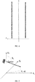
The road coordinate system is a world coordinate system, and preferably takes a lane direction as an x axis, a direction vertical to the x axis and a road surface as a z axis and a direction vertical to the x axis and the z axis as a y axis; and an original point may be located in the center of the lane, so that two lanes may be symmetrical along the x axis.FIG. 4 is a schematic diagram of a road coordinate system when z=0 according to an embodiment of the present disclosure, wherein two straight lines parallel to the x axis represent lane. - Step S320: establish a camera coordinate system.
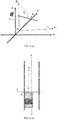
FIG. 5 is a schematic diagram of a camera coordinate system according to an embodiment of the present disclosure, wherein the camera coordinate system may be established on the basis of a vehicle, and preferably takes a vehicle traveling direction as an xc axis, a direction vertical to the xc axis and a vehicle body as a zc axis and a direction vertical to the xc axis and the zc axis as a yc axis. The coordinates of the camera position are (0, 0, zcamera), wherein the zcamera is the height of the camera relative to the position on the vehicle as the original point of the camera coordinate system. ϕc is an azimuth angle and is 0 in the figure, and θc is an elevation angle. The camera is essentially a converter from an actual 3D field to a 2D image surface. The acquired camera image will be changed by adjusting the angle and position of the camera, that is, parameters zcamera, ϕc, θc, etc. - Step S330: determine a relative relation between the road coordinate system and the camera coordinate system.
- Wherein, the relative relation includes a lateral shift of the camera relative to the center of the lane and an angle between a vehicle direction and a lane direction. Here, the vehicle direction is as same as a direction indicated by the azimuth angle of the camera.
- In a preferred embodiment, determine the relative relation includes: integrate the road coordinate system and the camera coordinate system into the same coordinate system on the basis of a road surface, and obtain a lateral movement value or a rotation value of the camera coordinate system with respect to the road coordinate system, determine the lateral shift based on the lateral movement value, and determine the angle based on the rotation value. The lateral shift and the angle are the relative relation that needs to be determined and are respectively set as yr and ϕr. When the two coordinate systems are integrated based on the road surface, the road coordinate system (the world coordinate system) is fixed, the camera coordinate system will move/rotate relative to the road coordinate system based on the yr and ϕr as the vehicle changes the lane. The movement/rotation is essentially the lateral shift of the camera relative to the center of the lane and the angle of the vehicle direction relative to the lane direction (referring to
FIG. 6 (c) and FIG. 6 (c) ), that is, the above lateral movement value is the lateral shift and the rotation value is the angle. It should be noted that the longitudinal movement of the two coordinate systems is ignored here. -
FIG. 6 (a) toFIG. 6 (c) are coordinate systems formed after a road coordinate system and a camera coordinate system are integrated, wherein inFIG. 6 (b) andFIG. 6 (c) , z=0 and zc=0; InFIG. 6 (a) , the camera position is (0, 0, zcamera), the direction (θc, ϕc) is equal to (θc, 0), and it is assumed that the x axis has little influence, inFIG. 6 (b) , relative toFIG. 6 (a) , the camera generates a lateral shift yr relative to the center of the lane, and inFIG. 6 (c) , relative toFIG. 6 (a) and FIG. 6 (b) , the vehicle deflects, and an angle ϕr is formed between the vehicle direction and the lane direction. - Step S340: determine a first domain is in the camera coordinate system.
- Wherein, the first domain requires that the lane be covered when the lateral shift and the angle are present.
-
FIG. 7 is a schematic diagram of a first domain according to an embodiment of the present disclosure. In the figure, zc=0. As shown inFIG. 7 , in a preferred embodiment, for the two corresponding lanes along the center line of the lane, the first domain is determined as two areas which are symmetrical along the xc axis, and each area covers one lane. As the vehicle runs, the relative relation of the road coordinate system and the camera coordinate system is changed, as above, that is, the camera coordinate system moves/rotates relative to the road coordinate system based on the lateral shift yr and the angle ϕr, and the first domain must ensure that even if the relative relation of the road coordinate system and the camera coordinate system is changed, the lane can be covered. - In this way, considering how the first domain covers the lane, it is necessary to define boundary conditions of the first domain, that is, to define boundary parameters such as wl1, wl2, L1, L2 and the like in
FIG. 7 . For example, Table 3 shows a group of boundary conditions.FIG. 8 is a schematic diagram of a first domain determined based on a boundary condition in Table 3. InFIG. 8 , yr=0, ϕr=0, a field of view (FOV) of the camera is, for example, 12.2 deg.Table 3 Boundary condition of the first domain Lane width (m) 3.75 Parameter Domain 1 x1(m) 10 x2 (m) 100 wl1, wr1 (LW) 0.2 Wl2, wr2 (LW) 0.7 wl1', wr1' (LW) 0 Wl2', wr2' (LW) 1.2 - The LW (Lane Width) represents the width of the lane, the parameters in the table such as x1, x2 and wl1 are configured corresponding to the lane width, and the meanings expressed by the parameters may be clearly understood with reference to
FIG. 7 , which are not elaborated herein. It should be noted that x1 is generally not taken as 0 because the camera is generally mounted at a rearview mirror of the vehicle and the camera cannot see a short driving distance in front of the vehicle due to the visual angle, for example, 10 m. therefore, x1 is, for example, taken as 10 m. - In a preferred embodiment, since whether the first domain can cover the lane is relevant to the lateral shift and the angle, the determination of the first domain may include: determining the lateral shift and the angle, determining a boundary parameter of the first domain such that the first domain satisfies the determined lateral shift and the determined angle, and constructing the first domain based on the determined boundary parameter.
- In a more preferred embodiment, the determination of the lateral shift and the angle includes: the lateral shift is determined to be one quarter of the lane width, and the angle is determined to be the half of the vehicle angle against the lane when doing the lane change. Here, it may be determined from the current rotating velocity, the lateral velocity, etc. of the vehicle that the half of the vehicle angle against the lane is about 2 deg when doing the lane change, that is, the angle is about 2 deg. For example, in Table 3, the lane width is 3.75 m. When the vehicle changes the lane, the lateral velocity is about 1.4 m/s at 80 km/h and the corresponding current angle is about 2 deg, then it may be determined that the lateral shift yr is 3.75/4 and the angle ϕr is 1 deg. Here, for the current angle and the determined angle ϕr, 2 deg and 1 deg are taken as examples below. In this way, to make the first domain cover the lane, the conditions required to be met are: the lateral shift of LW/4 and the angle ϕr of 1 deg. Through the application to the actual road, when the lane detection reaches 150 m, the lateral shift of LW/4 and the angle ϕr of 1 deg are sufficient, and when the lane detection focuses on short distance (for example, <50m), adaptive adjustment may be performed.
- With reference to the example in Table 3, Table 4 shows the boundary condition of two first domain meeting the condition, and
FIG. 9 is a schematic diagram of the first domain determined based on the boundary condition in Table 4. In the figure, yr=LW/4, ϕr=1 deg, and FOV, for example, is 12.2 deg.Table 4 Boundary condition of the first domain Lane Width (LW, m) 3.75 Parameter Domain 1 Domain 2x1 (m) 10 50 x2 (m) 50 100 wl1, wr1 (LW) 0.2 0 Wl1, wr2 (LW) 0.7 1 wl1', wr1' (LW) 0 0 W12', wr2' (LW) 1.2 1.7 domain 1 and thedomain 2 are respectively 10m to 50 m and 50 m to 100 m, which indicates that the lane detection may reach 100 m, and the reason for not detecting 10 m in front of the vehicle is as above that the camera cannot see the short distance in front of the vehicle. - Step S350: convert the first domain to the analysis area in the camera image based on the camera coordinate system.
- In the embodiment of the present disclosure, the coordinates on the camera coordinate system established based on the physical position of the camera may be converted into the coordinates in the corresponding camera image through conversion parameters such as a rotation matrix, a camera internal reference matrix and the like. Here, the coordinate conversion between the camera coordinate system and the corresponding camera image is already an existing mature technology, which will not be elaborated herein.
- Taking the first domain in
FIG. 8 as an example,FIG. 10 is a schematic diagram of an analysis area in a camera image corresponding to the first domain inFIG. 8 , wherein L1 and L2 are lanes and are covered with a left domain and a right domain respectively. - The following will undertake the examples in
FIG. 1 and FIG. 2 to further describe some details and advantages of performing lane detection based on the analysis area determined by the embodiment of the present disclosure. - The example specifically includes the process of the following parts:
- a) according to the process shown in
FIG. 1 , the step 1) and step 2) are performed to acquire an image and perform color selection. - b) in the step 3), the analysis area is determined by the method according to the embodiment of the present disclosure.
Compared with the traditional analysis area shown inFIG. 2 ,FIG. 11 is a schematic diagram of the analysis area determined by the method according to an embodiment of the present disclosure. In the figure, Rect_area represents a box where the traditional analysis area is located, and a shadow filled area in the Rect_area is the analysis area finally determined by the method according to the embodiment of the present disclosure. It can be seen that all unnecessary areas inFIG. 2 are not included in the newly determined analysis area. - c) For the analysis area shown in
FIG. 11 , the step 4) and step 5) are continuously performed.
Here, taking the differential image as an example, the calculation of the differential image in the analysis area will be easier. Specifically, it is supposed that the differential image in the Rect_area is DDD0(m, n) and the analysis area image in the Rect_area is AAA(m, n), if there is an analysis area in the Rect_area, the DDD0(m, n) is 1, otherwise the DDD0(m, n) is 0, and the AAA and the DDDO respectively represent multiplication of corresponding pixels, that is:
The DDD(m, n) is the finally acquired differential image, and it can be known that the DDD(m, n) does not include those areas outside the analysis area.
Understandably, the calculation of other image processing in the step 4) to step (5) in the analysis area will be easier. - d) A ternary image is acquired and processed.
- Specifically, through the step 6), the ternary image may be acquired by applying a threshold to the DDD(m, n). The ternary image may include important information (important differential points) because the ternary image covers the analysis area. Unnecessary points in the equation (1) are eliminated. Image processing involved in the step 7) may be defined in the analysis area for processing, and a good lane estimation result may be obtained.
- In addition, in a preferred embodiment, the first domain in the example may adaptively change over time, for example, the first domain in this measurement may be changed according to the lane position measured last time along with time change. For example, if the vehicle moves rightwards from the lane center, the first domain may be changed to the left to keep the lane in the analysis area. In a similar way, if the vehicle direction inclines to the right, the first domain may be changed to the left side. The analysis area in the finally formed camera image will change correspondingly to ensure the coverage of the lane, as shown in
FIG. 12 (a) and FIG. 12 (b). FIG. 12 (a) is a schematic diagram of the analysis area when the vehicle is located in the lane center, and the white part in the figure represents the analysis area.FIG. 12 (b) is a schematic diagram of the analysis area correspondingly obtained by changing the first domain to the left after the vehicle moves from the lane center to the right, and it can be known that the analysis area is also changed to the left. - In conclusion, the embodiment of the present disclosure achieves theoretical determination of the analysis area where image processing is applied in lane detection, thereby eliminating calculation and processing on unnecessary image areas, accelerating the lane detection and inhibiting noise in a differential image, thereby realizing more reliable lane detection. Through verification on the actual road surface, it is proved that by the method provided by the embodiment of the present disclosure, the speed and the precision of the lane detection can be improved.
- Another embodiment of the present disclosure further provides a machine readable storage medium, wherein the machine readable storage medium stores instructions for causing a controller to perform the method of determining the analysis area in the lane detection described in the above embodiment.
- Another embodiment of the present disclosure further provides an device for determining an analysis area in lane detection, which has the invention ideal as same as that of the method of determining the analysis area in the lane detection described in the above embodiment.
FIG. 13 is a structural schematic diagram of an device for determining an analysis area in lane detection according to an embodiment of the present disclosure, wherein the lane detection includes: performing image processing of a camera image captured by a camera on a vehicle, and the analysis area is an area in the camera image that is confined to perform the image processing. Referring toFIG. 13 , the device includes: a first coordinate system establishing module 110, configured to establish a road coordinate system; a second coordinatesystem establishing module 120, configured to establish a camera coordinate system; a relativerelation determining module 130, configured to determine a relative relation between the road coordinate system and the camera coordinate system, wherein the relative relation includes a lateral shift of the camera relative to a center of the lane and an angle between a vehicle direction and a lane direction; adomain determining module 140, configured to determine a first domain in the camera coordinate system, wherein the first domain requires that the lane be covered when the lateral shift and the angle are present; and adomain conversion module 150, configured to convert the first domain to the analysis area in the camera image based on the camera coordinate system. - In a preferred embodiment, the relative
relation determining module 130 is configured to determine the relative relation between the road coordinate system and the camera coordinate system, which may include: integrating the road coordinate system and the camera coordinate system into the same coordinate on the basis of a road surface, and obtaining a lateral movement value or a rotation value of the camera coordinate system with respect to the road coordinate system, determining the lateral shift based on the lateral movement value, and determining the angle based on the rotation value. - In a preferred embodiment, the
domain determining module 140 is configured to determine the first domain in the camera coordinate system, which may include: determining the lateral shift and the angle, determining a boundary parameter of the first domain such that the first domain satisfies the determined lateral shift and the determined angles, and constructing the first domain based on the determined boundary parameter. More preferably, the determination of the lateral shift and the angle may include: the lateral shift is determined to be one quarter of the lane width, and the angle is determined to be the half of the vehicle angle against the lane when doing the lane change. - Here, the details and advantages of the specific embodiments of the device according to the embodiment of the present disclosure are as same as or similar to the above method of determining the analysis area in the lane detection, which will not be elaborated herein.
- The above are only the preferred embodiments of the present disclosure, and are not intended to limit the present disclosure. Any modifications, equivalent substitutions, improvements and the like made within the spirit and principles of the present disclosure, for example, adaptive change of the execution sequence of steps and the connection relationship between functional modules, should fall within the protection scope of the present disclosure.
- Those skilled in the art may understand that implementing of all or some of steps in the methods of the foregoing embodiments may be completed by instructing relevant hardware through a program. The program is stored in a storage medium and includes a plurality of instructions for enabling a single chip, a chip or a processor to perform all or some of steps in the method of each embodiment of the present application. The foregoing storage medium includes: various medium that may store program codes, such as a USB flash disk, a mobile hard disk, a read-only memory (ROM), a random access memory (RAM), a magnetic disk, or an optical disc.
- In addition, various different embodiments of the embodiments of the present disclosure may be combined arbitrarily, which should be regarded as the contents disclosed by the embodiments of the present disclosure, as long as they do not violate the idea of the embodiments of the present disclosure.
Claims (10)
- A method of determining an analysis area in lane detection, wherein the lane detection comprises performing image processing of a camera image captured by a camera on a vehicle, and the analysis area is an area in the camera image that is confined to perform the image processing, and the method includes:establishing a road coordinate system;establishing a camera coordinate system;determining a relative relation between the road coordinate system and the camera coordinate system, wherein the relative relation comprises a lateral shift of the camera relative to a center of the lane and an angle between a vehicle direction and a lane direction, where it is assumed that the vehicle direction and an azimuth angle of the camera are the same;determining a first domain in the camera coordinate system, wherein the first domain requires that the lane be covered when the lateral shift and the angle are present; andconverting the first domain to the analysis area in the camera image based on the camera coordinate system.
- The method of claim 1, wherein determining a relative relation between the road coordinate system and the camera coordinate system comprises:
integrating the road coordinate system and the camera coordinate system into the same coordinate system on the basis of a road surface, and obtaining a lateral movement value or a rotation value of the camera coordinate system with respect to the road coordinate system, determining the lateral shift based on the lateral movement value, and determining the angle based on the rotation value. - The method for claim 1, wherein determining a first domain in the camera coordinate system comprises:
determining the lateral shift and the angle, determining a boundary parameter of the first domain such that the first domain satisfies the determined lateral shift and the determined angle, and constructing the first domain based on the determined boundary parameter. - The method of claim 3, wherein determining the lateral shift and the angle comprises:
determining the lateral shift is one quarter of the lane width, and the angle-is the half of the vehicle angle against the lane when doing the lane change. - The method of claim 1, wherein the first domain is adaptively changeable over time.
- A machine readable storage medium which stores instructions for causing a controller to perform the method of any one of claims 1 to 5.
- A device for determining an analysis area in lane detection, wherein the lane detection comprises performing image processing of a camera image captured by a camera on a vehicle, and the analysis area is an area in the camera image that is confined to perform the image processing, and the device includes:a first coordinate system establishing module, configured to establish a road coordinate system;a second coordinate system establishing module, configured to establish a camera coordinate system;a relative relation determining module, configured to determine a relative relation between the road coordinate system and the camera coordinate system, wherein the relative relation comprises a lateral shift of the camera relative to a center of the lane and an angle between a vehicle direction and a lane direction, where it is assumed that the vehicle direction and the azimuth angle of the camera are the same;a domain determining module, configured to determine a first domain in the camera coordinate system, wherein the first domain requires that the lane be covered when the lateral shift and the angle are present; anda domain conversion module, configured to convert the first domain to the analysis area in the camera image based on the camera coordinate system.
- The device of claim 7, wherein the relative relation determining module is configured to determine a relative relation between the road coordinate system and the camera coordinate system comprises:
integrating the road coordinate system and the camera coordinate system into the same coordinate system on the basis of a road surface, and obtaining a lateral movement value or a rotation value of the camera coordinate system with respect to the road coordinate system, determining the lateral shift based on the lateral movement value, and determining the angle based on the rotation value. - The device of claim 7, wherein the domain determining module is configured to determine a first domain in the camera coordinate system comprises:
determining the lateral shift and the angle, determining a boundary parameter of the first domain such that the first domain satisfies the determined lateral shift and the determined angles, and constructing the first domain based on the determined boundary parameter. - The device of claim 9, wherein determining the lateral shift and the angle comprises:
determining the lateral shift is one quarter of the lane width, and determining the angle is the half of the vehicle angle against the lane when doing the lane change.
Applications Claiming Priority (2)
| Application Number | Priority Date | Filing Date | Title |
|---|---|---|---|
| CN201811084084.6A CN110909575B (en) | 2018-09-17 | 2018-09-17 | Method and device for determining analysis area in lane line detection |
| PCT/CN2019/106105 WO2020057485A1 (en) | 2018-09-17 | 2019-09-17 | Method and device for determining analysis region for lane detection |
Publications (3)
| Publication Number | Publication Date |
|---|---|
| EP3855344A1 true EP3855344A1 (en) | 2021-07-28 |
| EP3855344A4 EP3855344A4 (en) | 2021-11-03 |
| EP3855344B1 EP3855344B1 (en) | 2024-06-26 |
Family
ID=69813525
Family Applications (1)
| Application Number | Title | Priority Date | Filing Date |
|---|---|---|---|
| EP19862778.8A Active EP3855344B1 (en) | 2018-09-17 | 2019-09-17 | Method and device for determining analysis region for lane detection |
Country Status (3)
| Country | Link |
|---|---|
| EP (1) | EP3855344B1 (en) |
| CN (1) | CN110909575B (en) |
| WO (1) | WO2020057485A1 (en) |
Families Citing this family (3)
| Publication number | Priority date | Publication date | Assignee | Title |
|---|---|---|---|---|
| CN114332130B (en) * | 2021-12-31 | 2024-12-27 | 智道网联科技(北京)有限公司 | Monocular camera acquisition method and device for high-precision images |
| US20230270337A1 (en) * | 2022-02-28 | 2023-08-31 | Hb Innovations, Inc. | System and method for video detection of breathing rates |
| CN115393812B (en) * | 2022-08-16 | 2025-07-11 | 厦门理工学院 | Infrared laser assisted lane line detection method, device, equipment and medium |
Family Cites Families (9)
| Publication number | Priority date | Publication date | Assignee | Title |
|---|---|---|---|---|
| CN101916516B (en) * | 2010-08-13 | 2012-07-11 | 深圳市豪恩汽车电子装备有限公司 | Lane deviation recognition method |
| CN103971081A (en) * | 2013-01-25 | 2014-08-06 | 株式会社理光 | Multi-lane detection method and system |
| KR101517181B1 (en) * | 2014-02-28 | 2015-05-04 | 주식회사 코아로직 | System and method for warning lane departure |
| CN104102905B (en) * | 2014-07-16 | 2018-03-16 | 中电海康集团有限公司 | A kind of adaptive detection method of lane line |
| KR102227843B1 (en) * | 2014-08-22 | 2021-03-15 | 현대모비스 주식회사 | Operating method of lane departure warning system |
| CN106326822B (en) * | 2015-07-07 | 2020-02-07 | 北京易车互联信息技术有限公司 | Method and device for detecting lane line |
| CN107330376B (en) * | 2017-06-06 | 2020-01-21 | 广州汽车集团股份有限公司 | Lane line identification method and system |
| CN107462223B (en) * | 2017-08-08 | 2020-06-16 | 长安大学 | A kind of automatic measuring device and measuring method of vehicle sight distance before road turning |
| CN108470142B (en) * | 2018-01-30 | 2021-09-03 | 西安电子科技大学 | Lane positioning method based on inverse perspective projection and lane distance constraint |
-
2018
- 2018-09-17 CN CN201811084084.6A patent/CN110909575B/en active Active
-
2019
- 2019-09-17 WO PCT/CN2019/106105 patent/WO2020057485A1/en not_active Ceased
- 2019-09-17 EP EP19862778.8A patent/EP3855344B1/en active Active
Also Published As
| Publication number | Publication date |
|---|---|
| EP3855344B1 (en) | 2024-06-26 |
| EP3855344A4 (en) | 2021-11-03 |
| CN110909575B (en) | 2023-04-18 |
| CN110909575A (en) | 2020-03-24 |
| WO2020057485A1 (en) | 2020-03-26 |
Similar Documents
| Publication | Publication Date | Title |
|---|---|---|
| JP7830407B2 (en) | Electronic devices, mobile devices, imaging devices, and control methods, programs, and storage media for electronic devices. | |
| US12340593B2 (en) | Vehicle drivable area detection method, system, and autonomous vehicle using the system | |
| Suhr et al. | Automatic parking space detection and tracking for underground and indoor environments | |
| EP3418943B1 (en) | Object detecting apparatus, object detecting method, and computer-readable medium | |
| US10977504B2 (en) | Vehicle-mounted image target objection recognition device | |
| US11250288B2 (en) | Information processing apparatus and information processing method using correlation between attributes | |
| LU502288B1 (en) | Method and system for detecting position relation between vehicle and lane line, and storage medium | |
| CN101750049B (en) | Monocular vision vehicle distance measuring method based on road and vehicle information | |
| CN109872329A (en) | A fast segmentation method of ground point cloud based on 3D lidar | |
| EP3855344B1 (en) | Method and device for determining analysis region for lane detection | |
| US11204610B2 (en) | Information processing apparatus, vehicle, and information processing method using correlation between attributes | |
| CN106228110A (en) | A kind of barrier based on vehicle-mounted binocular camera and drivable region detection method | |
| WO2009081920A1 (en) | Moving state estimation device | |
| US20240271945A1 (en) | Vehicle, Vehicle Positioning Method and Apparatus, Device, and Computer-Readable Storage Medium | |
| Raguraman et al. | Intelligent drivable area detection system using camera and lidar sensor for autonomous vehicle | |
| Kellner et al. | Multi-cue, model-based detection and mapping of road curb features using stereo vision | |
| CN113408353A (en) | Real-time obstacle avoidance system based on RGB-D | |
| US20090052779A1 (en) | Object recognizing apparatus | |
| JP2020047210A (en) | Object detection device | |
| CN113033253A (en) | Camera calibration method and device | |
| Lategahn et al. | Occupancy grid computation from dense stereo and sparse structure and motion points for automotive applications | |
| US12233861B2 (en) | Object recognition apparatus and non-transitory recording medium | |
| Lin et al. | Construction of fisheye lens inverse perspective mapping model and its applications of obstacle detection | |
| Raaijmakers et al. | Circle detection in single-layer laser scans for roundabout perception | |
| CN115731123A (en) | Automatic extraction method and device for high-precision map lane line |
Legal Events
| Date | Code | Title | Description |
|---|---|---|---|
| STAA | Information on the status of an ep patent application or granted ep patent |
Free format text: STATUS: THE INTERNATIONAL PUBLICATION HAS BEEN MADE |
|
| PUAI | Public reference made under article 153(3) epc to a published international application that has entered the european phase |
Free format text: ORIGINAL CODE: 0009012 |
|
| STAA | Information on the status of an ep patent application or granted ep patent |
Free format text: STATUS: REQUEST FOR EXAMINATION WAS MADE |
|
| 17P | Request for examination filed |
Effective date: 20210331 |
|
| AK | Designated contracting states |
Kind code of ref document: A1 Designated state(s): AL AT BE BG CH CY CZ DE DK EE ES FI FR GB GR HR HU IE IS IT LI LT LU LV MC MK MT NL NO PL PT RO RS SE SI SK SM TR |
|
| A4 | Supplementary search report drawn up and despatched |
Effective date: 20211005 |
|
| RIC1 | Information provided on ipc code assigned before grant |
Ipc: G06K 9/00 20060101AFI20210929BHEP |
|
| DAV | Request for validation of the european patent (deleted) | ||
| DAX | Request for extension of the european patent (deleted) | ||
| STAA | Information on the status of an ep patent application or granted ep patent |
Free format text: STATUS: EXAMINATION IS IN PROGRESS |
|
| 17Q | First examination report despatched |
Effective date: 20220704 |
|
| REG | Reference to a national code |
Ref legal event code: R079 Ipc: G06V0020580000 Ref country code: DE Ref legal event code: R079 Ref document number: 602019054366 Country of ref document: DE Free format text: PREVIOUS MAIN CLASS: G06K0009000000 Ipc: G06V0020580000 |
|
| GRAP | Despatch of communication of intention to grant a patent |
Free format text: ORIGINAL CODE: EPIDOSNIGR1 |
|
| STAA | Information on the status of an ep patent application or granted ep patent |
Free format text: STATUS: GRANT OF PATENT IS INTENDED |
|
| RIC1 | Information provided on ipc code assigned before grant |
Ipc: G06V 20/58 20220101AFI20240108BHEP |
|
| INTG | Intention to grant announced |
Effective date: 20240123 |
|
| P01 | Opt-out of the competence of the unified patent court (upc) registered |
Effective date: 20240307 |
|
| GRAS | Grant fee paid |
Free format text: ORIGINAL CODE: EPIDOSNIGR3 |
|
| GRAA | (expected) grant |
Free format text: ORIGINAL CODE: 0009210 |
|
| STAA | Information on the status of an ep patent application or granted ep patent |
Free format text: STATUS: THE PATENT HAS BEEN GRANTED |
|
| AK | Designated contracting states |
Kind code of ref document: B1 Designated state(s): AL AT BE BG CH CY CZ DE DK EE ES FI FR GB GR HR HU IE IS IT LI LT LU LV MC MK MT NL NO PL PT RO RS SE SI SK SM TR |
|
| REG | Reference to a national code |
Ref country code: GB Ref legal event code: FG4D |
|
| REG | Reference to a national code |
Ref country code: CH Ref legal event code: EP |
|
| REG | Reference to a national code |
Ref country code: DE Ref legal event code: R096 Ref document number: 602019054366 Country of ref document: DE |
|
| PG25 | Lapsed in a contracting state [announced via postgrant information from national office to epo] |
Ref country code: BG Free format text: LAPSE BECAUSE OF FAILURE TO SUBMIT A TRANSLATION OF THE DESCRIPTION OR TO PAY THE FEE WITHIN THE PRESCRIBED TIME-LIMIT Effective date: 20240626 |
|
| PG25 | Lapsed in a contracting state [announced via postgrant information from national office to epo] |
Ref country code: FI Free format text: LAPSE BECAUSE OF FAILURE TO SUBMIT A TRANSLATION OF THE DESCRIPTION OR TO PAY THE FEE WITHIN THE PRESCRIBED TIME-LIMIT Effective date: 20240626 Ref country code: HR Free format text: LAPSE BECAUSE OF FAILURE TO SUBMIT A TRANSLATION OF THE DESCRIPTION OR TO PAY THE FEE WITHIN THE PRESCRIBED TIME-LIMIT Effective date: 20240626 |
|
| REG | Reference to a national code |
Ref country code: LT Ref legal event code: MG9D |
|
| PG25 | Lapsed in a contracting state [announced via postgrant information from national office to epo] |
Ref country code: GR Free format text: LAPSE BECAUSE OF FAILURE TO SUBMIT A TRANSLATION OF THE DESCRIPTION OR TO PAY THE FEE WITHIN THE PRESCRIBED TIME-LIMIT Effective date: 20240927 |
|
| PG25 | Lapsed in a contracting state [announced via postgrant information from national office to epo] |
Ref country code: LV Free format text: LAPSE BECAUSE OF FAILURE TO SUBMIT A TRANSLATION OF THE DESCRIPTION OR TO PAY THE FEE WITHIN THE PRESCRIBED TIME-LIMIT Effective date: 20240626 |
|
| REG | Reference to a national code |
Ref country code: NL Ref legal event code: MP Effective date: 20240626 |
|
| PG25 | Lapsed in a contracting state [announced via postgrant information from national office to epo] |
Ref country code: NO Free format text: LAPSE BECAUSE OF FAILURE TO SUBMIT A TRANSLATION OF THE DESCRIPTION OR TO PAY THE FEE WITHIN THE PRESCRIBED TIME-LIMIT Effective date: 20240926 Ref country code: LV Free format text: LAPSE BECAUSE OF FAILURE TO SUBMIT A TRANSLATION OF THE DESCRIPTION OR TO PAY THE FEE WITHIN THE PRESCRIBED TIME-LIMIT Effective date: 20240626 Ref country code: HR Free format text: LAPSE BECAUSE OF FAILURE TO SUBMIT A TRANSLATION OF THE DESCRIPTION OR TO PAY THE FEE WITHIN THE PRESCRIBED TIME-LIMIT Effective date: 20240626 Ref country code: GR Free format text: LAPSE BECAUSE OF FAILURE TO SUBMIT A TRANSLATION OF THE DESCRIPTION OR TO PAY THE FEE WITHIN THE PRESCRIBED TIME-LIMIT Effective date: 20240927 Ref country code: FI Free format text: LAPSE BECAUSE OF FAILURE TO SUBMIT A TRANSLATION OF THE DESCRIPTION OR TO PAY THE FEE WITHIN THE PRESCRIBED TIME-LIMIT Effective date: 20240626 Ref country code: BG Free format text: LAPSE BECAUSE OF FAILURE TO SUBMIT A TRANSLATION OF THE DESCRIPTION OR TO PAY THE FEE WITHIN THE PRESCRIBED TIME-LIMIT Effective date: 20240626 Ref country code: RS Free format text: LAPSE BECAUSE OF FAILURE TO SUBMIT A TRANSLATION OF THE DESCRIPTION OR TO PAY THE FEE WITHIN THE PRESCRIBED TIME-LIMIT Effective date: 20240926 |
|
| PG25 | Lapsed in a contracting state [announced via postgrant information from national office to epo] |
Ref country code: NL Free format text: LAPSE BECAUSE OF FAILURE TO SUBMIT A TRANSLATION OF THE DESCRIPTION OR TO PAY THE FEE WITHIN THE PRESCRIBED TIME-LIMIT Effective date: 20240626 |
|
| REG | Reference to a national code |
Ref country code: AT Ref legal event code: MK05 Ref document number: 1698374 Country of ref document: AT Kind code of ref document: T Effective date: 20240626 |
|
| PG25 | Lapsed in a contracting state [announced via postgrant information from national office to epo] |
Ref country code: NL Free format text: LAPSE BECAUSE OF FAILURE TO SUBMIT A TRANSLATION OF THE DESCRIPTION OR TO PAY THE FEE WITHIN THE PRESCRIBED TIME-LIMIT Effective date: 20240626 |
|
| PG25 | Lapsed in a contracting state [announced via postgrant information from national office to epo] |
Ref country code: PT Free format text: LAPSE BECAUSE OF FAILURE TO SUBMIT A TRANSLATION OF THE DESCRIPTION OR TO PAY THE FEE WITHIN THE PRESCRIBED TIME-LIMIT Effective date: 20241028 |
|
| PG25 | Lapsed in a contracting state [announced via postgrant information from national office to epo] |
Ref country code: PT Free format text: LAPSE BECAUSE OF FAILURE TO SUBMIT A TRANSLATION OF THE DESCRIPTION OR TO PAY THE FEE WITHIN THE PRESCRIBED TIME-LIMIT Effective date: 20241028 |
|
| PG25 | Lapsed in a contracting state [announced via postgrant information from national office to epo] |
Ref country code: PL Free format text: LAPSE BECAUSE OF FAILURE TO SUBMIT A TRANSLATION OF THE DESCRIPTION OR TO PAY THE FEE WITHIN THE PRESCRIBED TIME-LIMIT Effective date: 20240626 |
|
| PG25 | Lapsed in a contracting state [announced via postgrant information from national office to epo] |
Ref country code: EE Free format text: LAPSE BECAUSE OF FAILURE TO SUBMIT A TRANSLATION OF THE DESCRIPTION OR TO PAY THE FEE WITHIN THE PRESCRIBED TIME-LIMIT Effective date: 20240626 |
|
| PG25 | Lapsed in a contracting state [announced via postgrant information from national office to epo] |
Ref country code: AT Free format text: LAPSE BECAUSE OF FAILURE TO SUBMIT A TRANSLATION OF THE DESCRIPTION OR TO PAY THE FEE WITHIN THE PRESCRIBED TIME-LIMIT Effective date: 20240626 Ref country code: IS Free format text: LAPSE BECAUSE OF FAILURE TO SUBMIT A TRANSLATION OF THE DESCRIPTION OR TO PAY THE FEE WITHIN THE PRESCRIBED TIME-LIMIT Effective date: 20241026 |
|
| PG25 | Lapsed in a contracting state [announced via postgrant information from national office to epo] |
Ref country code: CZ Free format text: LAPSE BECAUSE OF FAILURE TO SUBMIT A TRANSLATION OF THE DESCRIPTION OR TO PAY THE FEE WITHIN THE PRESCRIBED TIME-LIMIT Effective date: 20240626 |
|
| PG25 | Lapsed in a contracting state [announced via postgrant information from national office to epo] |
Ref country code: RO Free format text: LAPSE BECAUSE OF FAILURE TO SUBMIT A TRANSLATION OF THE DESCRIPTION OR TO PAY THE FEE WITHIN THE PRESCRIBED TIME-LIMIT Effective date: 20240626 Ref country code: SK Free format text: LAPSE BECAUSE OF FAILURE TO SUBMIT A TRANSLATION OF THE DESCRIPTION OR TO PAY THE FEE WITHIN THE PRESCRIBED TIME-LIMIT Effective date: 20240626 |
|
| PG25 | Lapsed in a contracting state [announced via postgrant information from national office to epo] |
Ref country code: ES Free format text: LAPSE BECAUSE OF FAILURE TO SUBMIT A TRANSLATION OF THE DESCRIPTION OR TO PAY THE FEE WITHIN THE PRESCRIBED TIME-LIMIT Effective date: 20240626 Ref country code: SM Free format text: LAPSE BECAUSE OF FAILURE TO SUBMIT A TRANSLATION OF THE DESCRIPTION OR TO PAY THE FEE WITHIN THE PRESCRIBED TIME-LIMIT Effective date: 20240626 |
|
| PG25 | Lapsed in a contracting state [announced via postgrant information from national office to epo] |
Ref country code: SM Free format text: LAPSE BECAUSE OF FAILURE TO SUBMIT A TRANSLATION OF THE DESCRIPTION OR TO PAY THE FEE WITHIN THE PRESCRIBED TIME-LIMIT Effective date: 20240626 Ref country code: SK Free format text: LAPSE BECAUSE OF FAILURE TO SUBMIT A TRANSLATION OF THE DESCRIPTION OR TO PAY THE FEE WITHIN THE PRESCRIBED TIME-LIMIT Effective date: 20240626 Ref country code: RO Free format text: LAPSE BECAUSE OF FAILURE TO SUBMIT A TRANSLATION OF THE DESCRIPTION OR TO PAY THE FEE WITHIN THE PRESCRIBED TIME-LIMIT Effective date: 20240626 Ref country code: PL Free format text: LAPSE BECAUSE OF FAILURE TO SUBMIT A TRANSLATION OF THE DESCRIPTION OR TO PAY THE FEE WITHIN THE PRESCRIBED TIME-LIMIT Effective date: 20240626 Ref country code: IS Free format text: LAPSE BECAUSE OF FAILURE TO SUBMIT A TRANSLATION OF THE DESCRIPTION OR TO PAY THE FEE WITHIN THE PRESCRIBED TIME-LIMIT Effective date: 20241026 Ref country code: ES Free format text: LAPSE BECAUSE OF FAILURE TO SUBMIT A TRANSLATION OF THE DESCRIPTION OR TO PAY THE FEE WITHIN THE PRESCRIBED TIME-LIMIT Effective date: 20240626 Ref country code: EE Free format text: LAPSE BECAUSE OF FAILURE TO SUBMIT A TRANSLATION OF THE DESCRIPTION OR TO PAY THE FEE WITHIN THE PRESCRIBED TIME-LIMIT Effective date: 20240626 Ref country code: CZ Free format text: LAPSE BECAUSE OF FAILURE TO SUBMIT A TRANSLATION OF THE DESCRIPTION OR TO PAY THE FEE WITHIN THE PRESCRIBED TIME-LIMIT Effective date: 20240626 Ref country code: AT Free format text: LAPSE BECAUSE OF FAILURE TO SUBMIT A TRANSLATION OF THE DESCRIPTION OR TO PAY THE FEE WITHIN THE PRESCRIBED TIME-LIMIT Effective date: 20240626 |
|
| PG25 | Lapsed in a contracting state [announced via postgrant information from national office to epo] |
Ref country code: IT Free format text: LAPSE BECAUSE OF FAILURE TO SUBMIT A TRANSLATION OF THE DESCRIPTION OR TO PAY THE FEE WITHIN THE PRESCRIBED TIME-LIMIT Effective date: 20240626 |
|
| REG | Reference to a national code |
Ref country code: DE Ref legal event code: R097 Ref document number: 602019054366 Country of ref document: DE |
|
| PG25 | Lapsed in a contracting state [announced via postgrant information from national office to epo] |
Ref country code: DK Free format text: LAPSE BECAUSE OF FAILURE TO SUBMIT A TRANSLATION OF THE DESCRIPTION OR TO PAY THE FEE WITHIN THE PRESCRIBED TIME-LIMIT Effective date: 20240626 |
|
| PG25 | Lapsed in a contracting state [announced via postgrant information from national office to epo] |
Ref country code: MC Free format text: LAPSE BECAUSE OF FAILURE TO SUBMIT A TRANSLATION OF THE DESCRIPTION OR TO PAY THE FEE WITHIN THE PRESCRIBED TIME-LIMIT Effective date: 20240626 |
|
| REG | Reference to a national code |
Ref country code: CH Ref legal event code: PL |
|
| PLBE | No opposition filed within time limit |
Free format text: ORIGINAL CODE: 0009261 |
|
| STAA | Information on the status of an ep patent application or granted ep patent |
Free format text: STATUS: NO OPPOSITION FILED WITHIN TIME LIMIT |
|
| PG25 | Lapsed in a contracting state [announced via postgrant information from national office to epo] |
Ref country code: LU Free format text: LAPSE BECAUSE OF NON-PAYMENT OF DUE FEES Effective date: 20240917 |
|
| 26N | No opposition filed |
Effective date: 20250327 |
|
| REG | Reference to a national code |
Ref country code: BE Ref legal event code: MM Effective date: 20240930 |
|
| PG25 | Lapsed in a contracting state [announced via postgrant information from national office to epo] |
Ref country code: BE Free format text: LAPSE BECAUSE OF NON-PAYMENT OF DUE FEES Effective date: 20240930 |
|
| PG25 | Lapsed in a contracting state [announced via postgrant information from national office to epo] |
Ref country code: CH Free format text: LAPSE BECAUSE OF NON-PAYMENT OF DUE FEES Effective date: 20240930 |
|
| PG25 | Lapsed in a contracting state [announced via postgrant information from national office to epo] |
Ref country code: IE Free format text: LAPSE BECAUSE OF NON-PAYMENT OF DUE FEES Effective date: 20240917 |
|
| PG25 | Lapsed in a contracting state [announced via postgrant information from national office to epo] |
Ref country code: SE Free format text: LAPSE BECAUSE OF FAILURE TO SUBMIT A TRANSLATION OF THE DESCRIPTION OR TO PAY THE FEE WITHIN THE PRESCRIBED TIME-LIMIT Effective date: 20240626 |
|
| PGFP | Annual fee paid to national office [announced via postgrant information from national office to epo] |
Ref country code: DE Payment date: 20250916 Year of fee payment: 7 |
|
| PGFP | Annual fee paid to national office [announced via postgrant information from national office to epo] |
Ref country code: GB Payment date: 20250919 Year of fee payment: 7 |
|
| PGFP | Annual fee paid to national office [announced via postgrant information from national office to epo] |
Ref country code: FR Payment date: 20250929 Year of fee payment: 7 |
|
| PG25 | Lapsed in a contracting state [announced via postgrant information from national office to epo] |
Ref country code: CY Free format text: LAPSE BECAUSE OF FAILURE TO SUBMIT A TRANSLATION OF THE DESCRIPTION OR TO PAY THE FEE WITHIN THE PRESCRIBED TIME-LIMIT; INVALID AB INITIO Effective date: 20190917 |
|
| PG25 | Lapsed in a contracting state [announced via postgrant information from national office to epo] |
Ref country code: HU Free format text: LAPSE BECAUSE OF FAILURE TO SUBMIT A TRANSLATION OF THE DESCRIPTION OR TO PAY THE FEE WITHIN THE PRESCRIBED TIME-LIMIT; INVALID AB INITIO Effective date: 20190917 |