EP3855282A1 - Resin pedal arm - Google Patents
Resin pedal arm Download PDFInfo
- Publication number
- EP3855282A1 EP3855282A1 EP19863009.7A EP19863009A EP3855282A1 EP 3855282 A1 EP3855282 A1 EP 3855282A1 EP 19863009 A EP19863009 A EP 19863009A EP 3855282 A1 EP3855282 A1 EP 3855282A1
- Authority
- EP
- European Patent Office
- Prior art keywords
- wall portion
- flat plate
- plate portions
- pedal arm
- arm body
- Prior art date
- Legal status (The legal status is an assumption and is not a legal conclusion. Google has not performed a legal analysis and makes no representation as to the accuracy of the status listed.)
- Withdrawn
Links
Images






Classifications
-
- G—PHYSICS
- G05—CONTROLLING; REGULATING
- G05G—CONTROL DEVICES OR SYSTEMS INSOFAR AS CHARACTERISED BY MECHANICAL FEATURES ONLY
- G05G1/00—Controlling members, e.g. knobs or handles; Assemblies or arrangements thereof; Indicating position of controlling members
- G05G1/30—Controlling members actuated by foot
- G05G1/50—Manufacturing of pedals; Pedals characterised by the material used
- G05G1/506—Controlling members for foot-actuation
-
- B—PERFORMING OPERATIONS; TRANSPORTING
- B60—VEHICLES IN GENERAL
- B60K—ARRANGEMENT OR MOUNTING OF PROPULSION UNITS OR OF TRANSMISSIONS IN VEHICLES; ARRANGEMENT OR MOUNTING OF PLURAL DIVERSE PRIME-MOVERS IN VEHICLES; AUXILIARY DRIVES FOR VEHICLES; INSTRUMENTATION OR DASHBOARDS FOR VEHICLES; ARRANGEMENTS IN CONNECTION WITH COOLING, AIR INTAKE, GAS EXHAUST OR FUEL SUPPLY OF PROPULSION UNITS IN VEHICLES
- B60K23/00—Arrangement or mounting of control devices for vehicle transmissions, or parts thereof, not otherwise provided for
- B60K23/02—Arrangement or mounting of control devices for vehicle transmissions, or parts thereof, not otherwise provided for for main transmission clutches
-
- B—PERFORMING OPERATIONS; TRANSPORTING
- B60—VEHICLES IN GENERAL
- B60K—ARRANGEMENT OR MOUNTING OF PROPULSION UNITS OR OF TRANSMISSIONS IN VEHICLES; ARRANGEMENT OR MOUNTING OF PLURAL DIVERSE PRIME-MOVERS IN VEHICLES; AUXILIARY DRIVES FOR VEHICLES; INSTRUMENTATION OR DASHBOARDS FOR VEHICLES; ARRANGEMENTS IN CONNECTION WITH COOLING, AIR INTAKE, GAS EXHAUST OR FUEL SUPPLY OF PROPULSION UNITS IN VEHICLES
- B60K26/00—Arrangement or mounting of propulsion-unit control devices in vehicles
- B60K26/02—Arrangement or mounting of propulsion-unit control devices in vehicles of initiating means or elements
-
- B—PERFORMING OPERATIONS; TRANSPORTING
- B60—VEHICLES IN GENERAL
- B60T—VEHICLE BRAKE CONTROL SYSTEMS OR PARTS THEREOF; BRAKE CONTROL SYSTEMS OR PARTS THEREOF, IN GENERAL; ARRANGEMENT OF BRAKING ELEMENTS ON VEHICLES IN GENERAL; PORTABLE DEVICES FOR PREVENTING UNWANTED MOVEMENT OF VEHICLES; VEHICLE MODIFICATIONS TO FACILITATE COOLING OF BRAKES
- B60T7/00—Brake-action initiating means
- B60T7/02—Brake-action initiating means for personal initiation
- B60T7/04—Brake-action initiating means for personal initiation foot actuated
- B60T7/06—Disposition of pedal
-
- B—PERFORMING OPERATIONS; TRANSPORTING
- B60—VEHICLES IN GENERAL
- B60T—VEHICLE BRAKE CONTROL SYSTEMS OR PARTS THEREOF; BRAKE CONTROL SYSTEMS OR PARTS THEREOF, IN GENERAL; ARRANGEMENT OF BRAKING ELEMENTS ON VEHICLES IN GENERAL; PORTABLE DEVICES FOR PREVENTING UNWANTED MOVEMENT OF VEHICLES; VEHICLE MODIFICATIONS TO FACILITATE COOLING OF BRAKES
- B60T7/00—Brake-action initiating means
- B60T7/02—Brake-action initiating means for personal initiation
- B60T7/04—Brake-action initiating means for personal initiation foot actuated
-
- B—PERFORMING OPERATIONS; TRANSPORTING
- B60—VEHICLES IN GENERAL
- B60Y—INDEXING SCHEME RELATING TO ASPECTS CROSS-CUTTING VEHICLE TECHNOLOGY
- B60Y2410/00—Constructional features of vehicle sub-units
- B60Y2410/12—Production or manufacturing of vehicle parts
- B60Y2410/122—Plastic parts manufactured by moulding
-
- G—PHYSICS
- G05—CONTROLLING; REGULATING
- G05G—CONTROL DEVICES OR SYSTEMS INSOFAR AS CHARACTERISED BY MECHANICAL FEATURES ONLY
- G05G1/00—Controlling members, e.g. knobs or handles; Assemblies or arrangements thereof; Indicating position of controlling members
- G05G1/30—Controlling members actuated by foot
- G05G1/44—Controlling members actuated by foot pivoting
Definitions
- the present embodiment relates to a resin pedal arm.
- an operation pedal turnably supported on a vehicle-body-side member of a vehicle includes an arm portion extending in a longitudinal direction from a base end portion as the center of rotation to a tip end portion to which operation force is applied and the arm portion includes a core formed in a hollow pipe shape and a reinforcing rib provided along a longitudinal direction of the core.
- the arm portion includes, according to the technique described in Patent Literature 1 below, the core formed in the hollow pipe shape and the reinforcing rib is provided along the outer periphery of the core, and therefore, required strength can be ensured while weight reduction can be realized and cost reduction can be also realized.
- a pedal arm to be attached to a vehicle includes an arm body having a front wall, a rear wall, a left wall, and a right wall corresponding to front-rear and right-left directions of the vehicle and formed as an integrally-molded article on which multiple ribs stand, a tread portion provided at a lower end portion of the arm body, a first hole penetrating the arm body in the right-left direction of the vehicle such that a first shaft fixed to a vehicle body side is insertable into the first hole, and a second hole penetrating the arm body in the right-left direction of the vehicle such that a second shaft connected to a control system of the vehicle is insertable into the second hole.
- the arm body further has a first curved portion curving in a backward direction of the vehicle as the arm body extends downward of the vehicle.
- the rear wall of the arm body formed continuously downward of the first curved portion is arranged on a lower side of the vehicle with respect to a first line connecting the tread portion and the first hole and a second line connecting the tread portion and the second hole.
- the multiple ribs include, at at least one of the left wall or the right wall, first ribs extending on the first line as laterally viewed to connect the first hole and a rear-wall-side peripheral edge portion of at least one of the left wall or the right wall at the arm body formed continuously upward of the first curved portion, and second ribs extending on the second line as laterally viewed to connect the second hole and the rear-wall-side peripheral edge portion of at least one of the left wall or the right wall at the arm body formed continuously upward of the first curved portion.
- the multiple ribs standing on the arm body have, at at least one of the left wall or the right wall of the arm body, the first ribs extending on the first line connecting the tread portion and the first hole as laterally viewed to connect the first hole into which the first shaft fixed to the vehicle side is insertable and the rear-wall-side peripheral edge portion of at least one of the left wall or the right wall formed continuously upward of the first curved portion curved in the backward direction of the vehicle as the arm body extends downward of the vehicle, and the second ribs extending on the second line connecting the tread portion and the second hole as laterally viewed to connect the second hole into which the second shaft connected to the control system of the vehicle is insertable and the rear-wall-side peripheral edge portion of at least one of the left wall or the right wall formed continuously upward of the first curved portion.
- the present embodiment has been made in view of the above-described points, and is intended to provide a resin pedal arm of which strength is further improved.
- an embodiment according to claim 1 is a resin pedal arm which includes a hollow arm body, the arm body including: a first wall portion; a second wall portion facing the first wall portion; a third wall portion formed between first edges of the first wall portion and the second wall portion and having multiple first flat plate portions arranged to bridge between the first edges; and a fourth wall portion formed between second edges of the first wall portion and the second wall portion, having multiple second flat plate portions arranged to bridge between the second edges, and facing the third wall portion, and the multiple second flat plate portions are each present in multiple opening areas each provided between adjacent ones of the multiple first flat plate portions, as viewed in a direction in which the third wall portion and the fourth wall portion face each other.
- An embodiment according to claim 2 is the resin pedal arm according to claim 1, further including: a tread portion provided at the arm body and stepped on in a forward direction of a vehicle to which the arm body is attached, in which the tread portion, the first wall portion, and the second wall portion are parallel with a vehicle width direction of the vehicle.
- An embodiment according to claim 3 is the resin pedal arm according to claim 1 or 2, in which the multiple first flat plate portions and the multiple second flat plate portions are provided in a predetermined region of the third wall portion and the fourth wall portion.
- the strength can be further improved.
- the resin pedal arm according to the present embodiment is a resin molded article manufactured by injection molding of molten resin, and is attached to a vehicle (not shown) and is used as a brake pedal.
- the resin pedal arm may be used as a vehicle pedal (e.g., an accelerator pedal or a clutch pedal) other than the brake pedal.
- vehicle pedal e.g., an accelerator pedal or a clutch pedal
- the vehicle to which the resin pedal arm according to the present embodiment is attached will be abbreviated as a vehicle.
- a direction from the plane of paper to a far side is a forward direction
- a direction from the plane of paper to a near side is a backward direction.
- a direction from the plane of paper to a far side is an upward direction
- a direction from the plane of paper to a near side is a downward direction.
- the right-left direction is coincident with a width direction of the resin pedal arm according to the present embodiment and a width direction (hereinafter referred to as a "vehicle width direction") of the vehicle.
- vehicle width direction a width direction of the resin pedal arm according to the present embodiment
- the width direction of the resin pedal arm according to the present embodiment will be sometimes expressed as the vehicle width direction.
- a resin pedal arm 10 of the first embodiment has an arm body 20 and a tread portion 22.
- the shape of the arm body 20 is a hollow shape. Details thereof will be described later.
- the tread portion 22 includes, e.g., a flat surface parallel with the vehicle width direction, and is provided on a rear side of a lower end portion of the arm body 20.
- a boss 24 and a clevis attachment hole 26 are provided at an upper end portion of the arm body 20.
- the boss 24 and the clevis attachment hole 26 have cylindrical shapes of which center axes are parallel with the vehicle width direction.
- a pivot pin (not shown) is inserted into the boss 24.
- the center of the boss 24 is the center of rotation of the arm body 20 when a driver of the vehicle steps on the tread portion 22 in the forward direction.
- a clevis pin (not shown) is inserted into the clevis attachment hole 26.
- a clevis is for turnably coupling a tip end portion of an operating rod (not shown) extending from a brake booster (not shown) of the vehicle to the arm body 20.
- the arm body 20 has a front wall portion 30, a rear wall portion 32, a left wall portion 34, and a right wall portion 36.
- the front wall portion 30 and the rear wall portion 32 are parallel with the vehicle width direction.
- the front wall portion 30 and the rear wall portion 32 face each other in a front-rear direction.
- Each of lower end portions of the front wall portion 30 and the rear wall portion 32 is in a shape bent to the backward direction, and is continuous to the tread portion 22.
- each of upper end portions of the front wall portion 30 and the rear wall portion 32 is, above the boss 24, continuous to each other in a curved form.
- the left wall portion 34 includes, e.g., multiple first flat plate portions 38.
- the multiple first flat plate portions 38 are, between a left edge 30A of the front wall portion 30 and a left edge 32A of the rear wall portion 32, arranged next to each other in a longitudinal direction of the arm body 20 in a state in which the multiple first flat plate portions 38 are continuous to the front wall portion 30 and the rear wall portion 32.
- each of multiple left opening areas S1 is formed between adjacent ones of the multiple first flat plate portions 38.
- the lowermost left opening area S1 of the multiple left opening areas S1 is formed between the first flat plate portion 38 and the tread portion 22.
- the right wall portion 36 includes, e.g., multiple second flat plate portions 40.
- the multiple second flat plate portions 40 are, between a right edge 30B of the front wall portion 30 and a right edge 32B of the rear wall portion 32, arranged next to each other in the longitudinal direction of the arm body 20 in a state in which the multiple second flat plate portions 40 are continuous to the front wall portion 30 and the rear wall portion 32.
- each of multiple right opening areas S2 is formed between adjacent ones of the multiple second flat plate portions 40.
- the uppermost right opening area S2 of the multiple right opening areas S2 is formed between the second flat plate portion 40 and the boss 24.
- the left wall portion 34 and the right wall portion 36 face each other in the right-left direction.
- circular openings of each of the boss 24 and the clevis attachment hole 26 are provided at the left wall portion 34 and the right wall portion 36.
- the multiple first flat plate portions 38 and the multiple second flat plate portions 40 are alternately arranged in the longitudinal direction of the arm body 20.
- the multiple second flat plate portions 40 are each present in the multiple left opening areas S1 as viewed from the side of the left wall portion 34 (i.e., as viewed in the right-left direction in which the left wall portion 34 and the right wall portion 36 face each other).
- the multiple first flat plate portions 38 are each present in the multiple right opening areas S2 as viewed from the side of the right wall portion 36 (i.e., as viewed in the right-left direction in which the left wall portion 34 and the right wall portion 36 face each other).
- section of the arm body 20 when the resin pedal arm 10 is cut along a line A-A of Fig. 4 is a hollow rectangular section (a so-called hollow square shape) illustrated in Fig. 5 .
- the resin pedal arm 10 of the first embodiment is manufactured by injection molding. Further, the front wall portion 30, the rear wall portion 32, the first flat plate portions 38 of the left wall portion 34, and the second flat plate portions 40 of the right wall portion 36 form the section of the arm body 20 into a shape close to the hollow rectangular section (the so-called hollow square shape) which is difficult to be shaped in injection molding. Thus, in the resin pedal arm 10 of the first embodiment, strength can be further improved.
- the front wall portion 30 and the rear wall portion 32 without the left opening areas S1 and the right opening areas S2 and the tread portion 22 are parallel with the vehicle width direction of the vehicle to which the arm body 20 is attached.
- die cutting is facilitated in injection molding for manufacturing the resin pedal arm 10.
- the arm body 20 of the first embodiment has a greater modulus of section for force (hereinafter referred to as "stepping force") when the driver steps on the tread portion 22 in the forward direction of the vehicle as compared to that in a later-described second embodiment.
- stepping force modulus of section for force
- the front wall portion 30 is one example of a "first wall portion.”
- the left edge 30A of the front wall portion 30 is one example of a "first edge.”
- the right edge 30B of the front wall portion 30 is one example of a "second edge.”
- the rear wall portion 32 is one example of a "second wall portion.”
- the left edge 32A of the rear wall portion 32 is one example of a "first edge.”
- the right edge 32B of the rear wall portion 32 is one example of a "second edge.”
- the left wall portion 34 is one example of a "third wall portion.”
- the right wall portion 36 is one example of a "fourth wall portion.”
- the multiple left opening areas S1 are one example of "multiple opening areas each provided between adjacent ones of multiple first flat plate portions.”
- an arm body 20 has a rear wall portion 60, a front wall portion 62, a left wall portion 64, and a right wall portion 66.
- the left wall portion 64 and the right wall portion 66 face each other in the right-left direction.
- circular openings of each of a boss 24 and a clevis attachment hole 26 are provided at the left wall portion 64 and the right wall portion 66.
- Each of lower end portions of the left wall portion 64 and the right wall portion 66 is in a shape bent in the backward direction, and is continuous to a tread portion 22.
- upper end portions of the left wall portion 64 and the right wall portion 66 are continuous to each other through the boss 24.
- the rear wall portion 60 includes, e.g., multiple first flat plate portions 68.
- the multiple first flat plate portions 68 are, between a rear edge 64A of the left wall portion 64 and a rear edge 66A of the right wall portion 66, arranged next to each other in a longitudinal direction of the arm body 20 in a state in which the multiple first flat plate portions 68 are continuous to the left wall portion 64 and the right wall portion 66.
- each of multiple rear opening areas P1 is formed between adjacent ones of the multiple first flat plate portions 68.
- the lowermost rear opening area P1 of the multiple rear opening areas P1 is formed between the first flat plate portion 68 and the tread portion 22.
- the uppermost rear opening area P1 is formed between the first flat plate portion 68 and the boss 24.
- the front wall portion 62 includes, e.g., multiple second flat plate portions 70.
- the multiple second flat plate portions 70 are, between a front edge 64B of the left wall portion 64 and a front edge 66B of the right wall portion 66, arranged next to each other in the longitudinal direction of the arm body 20 in a state in which the multiple second flat plate portions 70 are continuous to the left wall portion 64 and the right wall portion 66.
- each of multiple front opening areas P2 is formed between adjacent ones of the multiple second flat plate portions 70.
- the multiple first flat plate portions 68 and the multiple second flat plate portions 70 are alternately arranged in the longitudinal direction of the arm body 20.
- the multiple second flat plate portions 70 are each present in the multiple rear opening areas P1 as viewed from the side of the rear wall portion 60 (i.e., as viewed in a front-rear direction in which the rear wall portion 60 and the front wall portion 62 face each other).
- the multiple first flat plate portions 68 are each present in the multiple front opening areas P2 as viewed from the side of the front wall portion 62 (i.e., as viewed in the front-rear direction in which the rear wall portion 60 and the front wall portion 62 face each other).
- section of the arm body 20 when the resin pedal arm 12 is cut along a line B-B of Fig. 8 is a hollow rectangular section (a so-called hollow square shape) illustrated in Fig. 10 .
- the resin pedal arm 12 of the second embodiment is manufactured by injection molding. Further, the first flat plate portions 68 of the rear wall portion 60, the second flat plate portions 70 of the front wall portion 62, the left wall portion 64, and the right wall portion 66 form the section of the arm body 20 into a shape close to the hollow rectangular section (the so-called hollow square shape) which is difficult to be shaped in injection molding. Thus, in the resin pedal arm 12 of the second embodiment, strength can be further improved.
- the left wall portion 64 is one example of a "first wall portion.”
- the rear edge 64A of the left wall portion 64 is one example of a "first edge.”
- the front edge 64B of the left wall portion 64 is one example of a "second edge.”
- the right wall portion 66 is one example of a "second wall portion.”
- the rear edge 66A of the right wall portion 66 is one example of a "first edge.”
- the front edge 66B of the right wall portion 66 is one example of a "second edge.”
- the rear wall portion 60 is one example of a "third wall portion.”
- the front wall portion 62 is one example of a "fourth wall portion.”
- the multiple rear opening areas P1 are one example of "multiple opening areas each provided between adjacent ones of multiple first flat plate portions.”
- the multiple first flat plate portions 38 and the multiple second flat plate portions 40 are, at the arm body 20, provided in a first predetermined region 100A extending downward of the boss 24.
- the multiple first flat plate portions 38 and the multiple second flat plate portions 40 are, at the resin pedal arm 10A, provided in the first predetermined region 100A (i.e., part of the arm body 20) of the left wall portion 34 and the right wall portion 36, and therefore, the degree of freedom for limitations due to injection molding is high.
- first predetermined region 100A is one example of a "predetermined region of a third wall portion and a fourth wall portion.”
- the multiple first flat plate portions 68 and the multiple second flat plate portions 70 are, at the arm body 20, provided in a second predetermined region 100B extending downward of the boss 24.
- the multiple first flat plate portions 68 and the multiple second flat plate portions 70 are, at the resin pedal arm 12A, provided in the second predetermined region 100B (i.e., part of the arm body 20) of the rear wall portion 60 and the front wall portion 62, and therefore, the degree of freedom for limitations due to injection molding is high.
- the second predetermined region 100B is one example of a "predetermined region of a third wall portion and a fourth wall portion.”
- first ribs R1 and multiple second ribs R2 are provided in the first embodiment.
- the multiple second ribs R2 are in a flat plate shape parallel with the right-left direction, and between the left wall portion 34 and the right wall portion 36, are provided in a state in which the second rib R2 extends from the second flat plate portion 40 to the left opening area S1 or a state in which the second rib R2 extends from the first flat plate portion 38 to the right opening area S2.
- the multiple first ribs R1 are in a flat plate shape, and between the left wall portion 34 and the right wall portion 36, are provided in a state in which the first rib R1 is continuous to a lower edge of the first flat plate portion 38 and an upper edge of the second flat plate portion 40 or a state in which the first rib R1 is continuous to an upper edge of the first flat plate portion 38 and a lower edge of the second flat plate portion 40.
- first rib R1 connecting the lower edge of the first flat plate portion 38 and the upper edge of the second flat plate portion 40 is in an inclined state in which the first rib R1 extends downwardly from the first flat plate portion 38 to the second flat plate portion 40.
- first rib R1 connecting the upper edge of the first flat plate portion 38 and the lower edge of the second flat plate portion 40 is in an inclined state in which the first rib R1 extends upwardly from the first flat plate portion 38 to the second flat plate portion 40.
- the multiple first ribs R1 are inclined with respect to the right-left direction in which the left wall portion 34 and the right wall portion 36 face each other, and as viewed in the right-left direction, are each present in the left opening areas S1 and the right opening areas S2.
- the multiple first ribs R1 do not interfere with die cutting in the right-left direction in injection molding for manufacturing the resin pedal arm 10B.
- a front edge of each of the multiple first ribs R1 and the multiple second ribs R2 is provided continuously to the front wall portion 30.
- a rear edge of each of the multiple first ribs R1 and the multiple second ribs R2 is provided continuously to the rear wall portion 32.
- the section of the arm body 20 when the resin pedal arm 10B having the above-described configuration is cut along a line C-C of Fig. 16 is a hollow rectangular section (a so-called hollow square shape) illustrated in Fig. 17 .
Landscapes
- Engineering & Computer Science (AREA)
- Transportation (AREA)
- Mechanical Engineering (AREA)
- Manufacturing & Machinery (AREA)
- Physics & Mathematics (AREA)
- General Physics & Mathematics (AREA)
- Automation & Control Theory (AREA)
- Chemical & Material Sciences (AREA)
- Combustion & Propulsion (AREA)
- Mechanical Control Devices (AREA)
- Braking Elements And Transmission Devices (AREA)
Abstract
Description
- The present embodiment relates to a resin pedal arm.
- Typically, various techniques have been proposed for a resin pedal arm. For example, a technique described in
Patent Literature 1 is characterized in that an operation pedal turnably supported on a vehicle-body-side member of a vehicle includes an arm portion extending in a longitudinal direction from a base end portion as the center of rotation to a tip end portion to which operation force is applied and the arm portion includes a core formed in a hollow pipe shape and a reinforcing rib provided along a longitudinal direction of the core. - With such a feature, the arm portion includes, according to the technique described in
Patent Literature 1 below, the core formed in the hollow pipe shape and the reinforcing rib is provided along the outer periphery of the core, and therefore, required strength can be ensured while weight reduction can be realized and cost reduction can be also realized. - Moreover, in a technique described in Patent Literature 2, a pedal arm to be attached to a vehicle includes an arm body having a front wall, a rear wall, a left wall, and a right wall corresponding to front-rear and right-left directions of the vehicle and formed as an integrally-molded article on which multiple ribs stand, a tread portion provided at a lower end portion of the arm body, a first hole penetrating the arm body in the right-left direction of the vehicle such that a first shaft fixed to a vehicle body side is insertable into the first hole, and a second hole penetrating the arm body in the right-left direction of the vehicle such that a second shaft connected to a control system of the vehicle is insertable into the second hole. The arm body further has a first curved portion curving in a backward direction of the vehicle as the arm body extends downward of the vehicle. The rear wall of the arm body formed continuously downward of the first curved portion is arranged on a lower side of the vehicle with respect to a first line connecting the tread portion and the first hole and a second line connecting the tread portion and the second hole. The multiple ribs include, at at least one of the left wall or the right wall, first ribs extending on the first line as laterally viewed to connect the first hole and a rear-wall-side peripheral edge portion of at least one of the left wall or the right wall at the arm body formed continuously upward of the first curved portion, and second ribs extending on the second line as laterally viewed to connect the second hole and the rear-wall-side peripheral edge portion of at least one of the left wall or the right wall at the arm body formed continuously upward of the first curved portion.
- In the technique described in Patent Literature 2 below, the multiple ribs standing on the arm body have, at at least one of the left wall or the right wall of the arm body, the first ribs extending on the first line connecting the tread portion and the first hole as laterally viewed to connect the first hole into which the first shaft fixed to the vehicle side is insertable and the rear-wall-side peripheral edge portion of at least one of the left wall or the right wall formed continuously upward of the first curved portion curved in the backward direction of the vehicle as the arm body extends downward of the vehicle, and the second ribs extending on the second line connecting the tread portion and the second hole as laterally viewed to connect the second hole into which the second shaft connected to the control system of the vehicle is insertable and the rear-wall-side peripheral edge portion of at least one of the left wall or the right wall formed continuously upward of the first curved portion. With such a feature, a vehicle pedal arm capable of realizing, with the minimum number of ribs, weight reduction while stress generated due to reactive force of stepping force is effectively reduced can be realized.
-
- PATENT LITERATURE 1:
WO 2018/003038 A - PATENT LITERATURE 2:
JP-A-2016-03 8722 - However, there has been room for improvement in arrangement of the ribs as reinforcing members in each of the techniques described in
Patent Literatures 1 and 2 above in terms of strength improvement. - Thus, the present embodiment has been made in view of the above-described points, and is intended to provide a resin pedal arm of which strength is further improved.
- In order to address the problem described above, an embodiment according to
claim 1 is a resin pedal arm which includes a hollow arm body, the arm body including: a first wall portion; a second wall portion facing the first wall portion; a third wall portion formed between first edges of the first wall portion and the second wall portion and having multiple first flat plate portions arranged to bridge between the first edges; and a fourth wall portion formed between second edges of the first wall portion and the second wall portion, having multiple second flat plate portions arranged to bridge between the second edges, and facing the third wall portion, and the multiple second flat plate portions are each present in multiple opening areas each provided between adjacent ones of the multiple first flat plate portions, as viewed in a direction in which the third wall portion and the fourth wall portion face each other. - An embodiment according to claim 2 is the resin pedal arm according to
claim 1, further including: a tread portion provided at the arm body and stepped on in a forward direction of a vehicle to which the arm body is attached, in which the tread portion, the first wall portion, and the second wall portion are parallel with a vehicle width direction of the vehicle. - An embodiment according to claim 3 is the resin pedal arm according to claim 1 or 2, in which the multiple first flat plate portions and the multiple second flat plate portions are provided in a predetermined region of the third wall portion and the fourth wall portion.
- In the resin pedal arm of the present embodiment, the strength can be further improved.
-
-
Fig. 1 is a perspective view of a resin pedal arm of a first embodiment. -
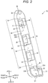
Fig. 2 is a perspective view of the resin pedal arm. -
Fig. 3 is a side view of the resin pedal arm. -
Fig. 4 is a front view of the resin pedal arm. -
Fig. 5 is a sectional view of the resin pedal arm along a line A-A ofFig. 4 . -
Fig. 6 is a perspective view of a resin pedal arm of a second embodiment. -
Fig. 7 is a perspective view of the resin pedal arm. -
Fig. 8 is a side view of the resin pedal arm. -
Fig. 9 is a front view of the resin pedal arm. -
Fig. 10 is a sectional view of the resin pedal arm along a line B-B ofFig. 8 . -
Fig. 11 is a perspective view of a variation of the resin pedal arm of the first embodiment. -
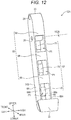
Fig. 12 is a perspective view of a variation of the resin pedal arm of the second embodiment. -
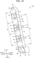
Fig. 13 is a perspective view of a variation of the resin pedal arm of the first embodiment. -
Fig. 14 is a perspective view of the resin pedal arm. -
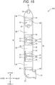
Fig. 15 is a side view of the resin pedal arm. -
Fig. 16 is a front view of the resin pedal arm. -
Fig. 17 is a sectional view of the resin pedal arm along a line C-C ofFig. 16 . - Hereinafter, a resin pedal arm according to the present embodiment will be described with reference to the drawings based on each specific embodiment. In each embodiment, the resin pedal arm according to the present embodiment is a resin molded article manufactured by injection molding of molten resin, and is attached to a vehicle (not shown) and is used as a brake pedal. Note that the resin pedal arm may be used as a vehicle pedal (e.g., an accelerator pedal or a clutch pedal) other than the brake pedal. Note that in description below, the vehicle to which the resin pedal arm according to the present embodiment is attached will be abbreviated as a vehicle.
- In each drawing used for description below, part of a basic configuration is omitted in an illustration, and the dimensions and the like of each component are not precisely illustrated. Moreover, directions in each figure are as illustrated in each figure. Note that in each of side views of
Figs. 3 ,8 , and15 , a direction from the plane of paper to a far side is a rightward direction, and a direction from the plane of paper to a near side is a leftward direction. That is, a direction perpendicular to the plane of paper of each ofFigs. 3 ,8 , and15 is a right-left direction. In each of front views ofFigs. 4 ,9 , and16 , a direction from the plane of paper to a far side is a forward direction, and a direction from the plane of paper to a near side is a backward direction. In each of sectional views ofFigs. 5 ,10 , and17 , a direction from the plane of paper to a far side is an upward direction, and a direction from the plane of paper to a near side is a downward direction. - Note that the right-left direction is coincident with a width direction of the resin pedal arm according to the present embodiment and a width direction (hereinafter referred to as a "vehicle width direction") of the vehicle. Moreover, in description below, the width direction of the resin pedal arm according to the present embodiment will be sometimes expressed as the vehicle width direction.
- First, a specific first embodiment of the present embodiment will be described. As illustrated in
Figs. 1 to 4 , aresin pedal arm 10 of the first embodiment has anarm body 20 and atread portion 22. The shape of thearm body 20 is a hollow shape. Details thereof will be described later. Thetread portion 22 includes, e.g., a flat surface parallel with the vehicle width direction, and is provided on a rear side of a lower end portion of thearm body 20. - A
boss 24 and aclevis attachment hole 26 are provided at an upper end portion of thearm body 20. Theboss 24 and theclevis attachment hole 26 have cylindrical shapes of which center axes are parallel with the vehicle width direction. - A pivot pin (not shown) is inserted into the
boss 24. Thus, the center of theboss 24 is the center of rotation of thearm body 20 when a driver of the vehicle steps on thetread portion 22 in the forward direction. A clevis pin (not shown) is inserted into theclevis attachment hole 26. Note that a clevis is for turnably coupling a tip end portion of an operating rod (not shown) extending from a brake booster (not shown) of the vehicle to thearm body 20. - The
arm body 20 has afront wall portion 30, arear wall portion 32, aleft wall portion 34, and aright wall portion 36. Thefront wall portion 30 and therear wall portion 32 are parallel with the vehicle width direction. Thus, thefront wall portion 30 and therear wall portion 32 face each other in a front-rear direction. Each of lower end portions of thefront wall portion 30 and therear wall portion 32 is in a shape bent to the backward direction, and is continuous to thetread portion 22. On the other hand, each of upper end portions of thefront wall portion 30 and therear wall portion 32 is, above theboss 24, continuous to each other in a curved form. - The
left wall portion 34 includes, e.g., multiple firstflat plate portions 38. - The multiple first
flat plate portions 38 are, between aleft edge 30A of thefront wall portion 30 and aleft edge 32A of therear wall portion 32, arranged next to each other in a longitudinal direction of thearm body 20 in a state in which the multiple firstflat plate portions 38 are continuous to thefront wall portion 30 and therear wall portion 32. Thus, each of multiple left opening areas S1 is formed between adjacent ones of the multiple firstflat plate portions 38. Note that the lowermost left opening area S1 of the multiple left opening areas S1 is formed between the firstflat plate portion 38 and thetread portion 22. - The
right wall portion 36 includes, e.g., multiple secondflat plate portions 40. The multiple secondflat plate portions 40 are, between aright edge 30B of thefront wall portion 30 and aright edge 32B of therear wall portion 32, arranged next to each other in the longitudinal direction of thearm body 20 in a state in which the multiple secondflat plate portions 40 are continuous to thefront wall portion 30 and therear wall portion 32. Thus, each of multiple right opening areas S2 is formed between adjacent ones of the multiple secondflat plate portions 40. Note that the uppermost right opening area S2 of the multiple right opening areas S2 is formed between the secondflat plate portion 40 and theboss 24. - The
left wall portion 34 and theright wall portion 36 face each other in the right-left direction. Thus, circular openings of each of theboss 24 and theclevis attachment hole 26 are provided at theleft wall portion 34 and theright wall portion 36. - At the
left wall portion 34 and theright wall portion 36, the multiple firstflat plate portions 38 and the multiple secondflat plate portions 40 are alternately arranged in the longitudinal direction of thearm body 20. The multiple secondflat plate portions 40 are each present in the multiple left opening areas S1 as viewed from the side of the left wall portion 34 (i.e., as viewed in the right-left direction in which theleft wall portion 34 and theright wall portion 36 face each other). On the other hand, the multiple firstflat plate portions 38 are each present in the multiple right opening areas S2 as viewed from the side of the right wall portion 36 (i.e., as viewed in the right-left direction in which theleft wall portion 34 and theright wall portion 36 face each other). - Further, the section of the
arm body 20 when theresin pedal arm 10 is cut along a line A-A ofFig. 4 is a hollow rectangular section (a so-called hollow square shape) illustrated inFig. 5 . - As described above in detail, the
resin pedal arm 10 of the first embodiment is manufactured by injection molding. Further, thefront wall portion 30, therear wall portion 32, the firstflat plate portions 38 of theleft wall portion 34, and the secondflat plate portions 40 of theright wall portion 36 form the section of thearm body 20 into a shape close to the hollow rectangular section (the so-called hollow square shape) which is difficult to be shaped in injection molding. Thus, in theresin pedal arm 10 of the first embodiment, strength can be further improved. - The
front wall portion 30 and therear wall portion 32 without the left opening areas S1 and the right opening areas S2 and thetread portion 22 are parallel with the vehicle width direction of the vehicle to which thearm body 20 is attached. Thus, die cutting is facilitated in injection molding for manufacturing theresin pedal arm 10. Further, thearm body 20 of the first embodiment has a greater modulus of section for force (hereinafter referred to as "stepping force") when the driver steps on thetread portion 22 in the forward direction of the vehicle as compared to that in a later-described second embodiment. Thus, strength against the stepping force can be further improved. - Note that in the first embodiment, the
front wall portion 30 is one example of a "first wall portion." Theleft edge 30A of thefront wall portion 30 is one example of a "first edge." Theright edge 30B of thefront wall portion 30 is one example of a "second edge." Therear wall portion 32 is one example of a "second wall portion." Theleft edge 32A of therear wall portion 32 is one example of a "first edge." Theright edge 32B of therear wall portion 32 is one example of a "second edge." Theleft wall portion 34 is one example of a "third wall portion." Theright wall portion 36 is one example of a "fourth wall portion." The multiple left opening areas S1 are one example of "multiple opening areas each provided between adjacent ones of multiple first flat plate portions." - Next, the specific second embodiment of the present embodiment will be described. Note that in description below, the same reference numerals are used to represent components substantially common to the first embodiment, and detailed description will be omitted.
- As illustrated in
Figs. 6 to 9 , in aresin pedal arm 12 of the second embodiment, anarm body 20 has arear wall portion 60, afront wall portion 62, aleft wall portion 64, and aright wall portion 66. - The
left wall portion 64 and theright wall portion 66 face each other in the right-left direction. Thus, circular openings of each of aboss 24 and aclevis attachment hole 26 are provided at theleft wall portion 64 and theright wall portion 66. Each of lower end portions of theleft wall portion 64 and theright wall portion 66 is in a shape bent in the backward direction, and is continuous to atread portion 22. On the other hand, upper end portions of theleft wall portion 64 and theright wall portion 66 are continuous to each other through theboss 24. - The
rear wall portion 60 includes, e.g., multiple firstflat plate portions 68. The multiple firstflat plate portions 68 are, between arear edge 64A of theleft wall portion 64 and arear edge 66A of theright wall portion 66, arranged next to each other in a longitudinal direction of thearm body 20 in a state in which the multiple firstflat plate portions 68 are continuous to theleft wall portion 64 and theright wall portion 66. Thus, each of multiple rear opening areas P1 is formed between adjacent ones of the multiple firstflat plate portions 68. Note that the lowermost rear opening area P1 of the multiple rear opening areas P1 is formed between the firstflat plate portion 68 and thetread portion 22. Moreover, the uppermost rear opening area P1 is formed between the firstflat plate portion 68 and theboss 24. - The
front wall portion 62 includes, e.g., multiple secondflat plate portions 70. The multiple secondflat plate portions 70 are, between afront edge 64B of theleft wall portion 64 and afront edge 66B of theright wall portion 66, arranged next to each other in the longitudinal direction of thearm body 20 in a state in which the multiple secondflat plate portions 70 are continuous to theleft wall portion 64 and theright wall portion 66. Thus, each of multiple front opening areas P2 is formed between adjacent ones of the multiple secondflat plate portions 70. - At the
rear wall portion 60 and thefront wall portion 62, the multiple firstflat plate portions 68 and the multiple secondflat plate portions 70 are alternately arranged in the longitudinal direction of thearm body 20. The multiple secondflat plate portions 70 are each present in the multiple rear opening areas P1 as viewed from the side of the rear wall portion 60 (i.e., as viewed in a front-rear direction in which therear wall portion 60 and thefront wall portion 62 face each other). On the other hand, the multiple firstflat plate portions 68 are each present in the multiple front opening areas P2 as viewed from the side of the front wall portion 62 (i.e., as viewed in the front-rear direction in which therear wall portion 60 and thefront wall portion 62 face each other). - Further, the section of the
arm body 20 when theresin pedal arm 12 is cut along a line B-B ofFig. 8 is a hollow rectangular section (a so-called hollow square shape) illustrated inFig. 10 . - As described above in detail, the
resin pedal arm 12 of the second embodiment is manufactured by injection molding. Further, the firstflat plate portions 68 of therear wall portion 60, the secondflat plate portions 70 of thefront wall portion 62, theleft wall portion 64, and theright wall portion 66 form the section of thearm body 20 into a shape close to the hollow rectangular section (the so-called hollow square shape) which is difficult to be shaped in injection molding. Thus, in theresin pedal arm 12 of the second embodiment, strength can be further improved. - Note that in the second embodiment, the
left wall portion 64 is one example of a "first wall portion." Therear edge 64A of theleft wall portion 64 is one example of a "first edge." Thefront edge 64B of theleft wall portion 64 is one example of a "second edge." Theright wall portion 66 is one example of a "second wall portion." Therear edge 66A of theright wall portion 66 is one example of a "first edge." Thefront edge 66B of theright wall portion 66 is one example of a "second edge." Therear wall portion 60 is one example of a "third wall portion." Thefront wall portion 62 is one example of a "fourth wall portion." The multiple rear opening areas P1 are one example of "multiple opening areas each provided between adjacent ones of multiple first flat plate portions." - Note that the present embodiment is not limited to each of the above-described embodiments, and various changes can be made without departing from the gist of the present embodiment. In description below, the same reference numerals are used to represent components substantially common to the first embodiment or the second embodiment, and detailed description will be omitted.
- In a
resin pedal arm 10A as a variation of the first embodiment as illustrated inFig. 11 , the multiple firstflat plate portions 38 and the multiple secondflat plate portions 40 are, at thearm body 20, provided in a firstpredetermined region 100A extending downward of theboss 24. - With the above-described configuration, the multiple first
flat plate portions 38 and the multiple secondflat plate portions 40 are, at theresin pedal arm 10A, provided in the firstpredetermined region 100A (i.e., part of the arm body 20) of theleft wall portion 34 and theright wall portion 36, and therefore, the degree of freedom for limitations due to injection molding is high. - Note that the first
predetermined region 100A is one example of a "predetermined region of a third wall portion and a fourth wall portion." - In a
resin pedal arm 12A as a variation of the second embodiment as illustrated inFig. 12 , the multiple firstflat plate portions 68 and the multiple secondflat plate portions 70 are, at thearm body 20, provided in a secondpredetermined region 100B extending downward of theboss 24. - With the above-described configuration, the multiple first
flat plate portions 68 and the multiple secondflat plate portions 70 are, at theresin pedal arm 12A, provided in the secondpredetermined region 100B (i.e., part of the arm body 20) of therear wall portion 60 and thefront wall portion 62, and therefore, the degree of freedom for limitations due to injection molding is high. - Note that the second
predetermined region 100B is one example of a "predetermined region of a third wall portion and a fourth wall portion." - In a
resin pedal arm 10B illustrated inFigs. 13 to 17 , multiple first ribs R1 and multiple second ribs R2 are provided in the first embodiment. - The multiple second ribs R2 are in a flat plate shape parallel with the right-left direction, and between the
left wall portion 34 and theright wall portion 36, are provided in a state in which the second rib R2 extends from the secondflat plate portion 40 to the left opening area S1 or a state in which the second rib R2 extends from the firstflat plate portion 38 to the right opening area S2. - The multiple first ribs R1 are in a flat plate shape, and between the
left wall portion 34 and theright wall portion 36, are provided in a state in which the first rib R1 is continuous to a lower edge of the firstflat plate portion 38 and an upper edge of the secondflat plate portion 40 or a state in which the first rib R1 is continuous to an upper edge of the firstflat plate portion 38 and a lower edge of the secondflat plate portion 40. - Thus, the first rib R1 connecting the lower edge of the first
flat plate portion 38 and the upper edge of the secondflat plate portion 40 is in an inclined state in which the first rib R1 extends downwardly from the firstflat plate portion 38 to the secondflat plate portion 40. On the other hand, the first rib R1 connecting the upper edge of the firstflat plate portion 38 and the lower edge of the secondflat plate portion 40 is in an inclined state in which the first rib R1 extends upwardly from the firstflat plate portion 38 to the secondflat plate portion 40. - With this configuration, the multiple first ribs R1 are inclined with respect to the right-left direction in which the
left wall portion 34 and theright wall portion 36 face each other, and as viewed in the right-left direction, are each present in the left opening areas S1 and the right opening areas S2. Thus, the multiple first ribs R1 do not interfere with die cutting in the right-left direction in injection molding for manufacturing theresin pedal arm 10B. - Note that a front edge of each of the multiple first ribs R1 and the multiple second ribs R2 is provided continuously to the
front wall portion 30. Moreover, a rear edge of each of the multiple first ribs R1 and the multiple second ribs R2 is provided continuously to therear wall portion 32. - The section of the
arm body 20 when theresin pedal arm 10B having the above-described configuration is cut along a line C-C ofFig. 16 is a hollow rectangular section (a so-called hollow square shape) illustrated inFig. 17 . -
- 10, 10A, 12, 12A
- resin pedal arm
- 20
- arm body
- 22
- tread portion
- 30
- front wall portion
- 30A
- left edge
- 30B
- right edge
- 32
- rear wall portion
- 32A
- left edge
- 32B
- right edge
- 34
- left wall portion
- 36
- right wall portion
- 38
- multiple first flat plate portions
- 40
- multiple second flat plate portions
- 60
- rear wall portion
- 62
- front wall portion
- 64
- left wall portion
- 64A
- rear edge
- 64B
- front edge
- 66
- right wall portion
- 66A
- rear edge
- 66B
- front edge
- 68
- multiple first flat plate portions
- 70
- multiple second flat plate portions
- S1
- left opening area
- S2
- right opening area
- P1
- rear opening area
- P2
- front opening area
- 100A
- first predetermined region
- 100B
- second predetermined region
Claims (3)
- A resin pedal arm comprising:a hollow arm body,wherein the arm body includesa first wall portion,a second wall portion facing the first wall portion,a third wall portion formed between first edges of the first wall portion and the second wall portion and having multiple first flat plate portions arranged to bridge between the first edges, anda fourth wall portion formed between second edges of the first wall portion and the second wall portion, having multiple second flat plate portions arranged to bridge between the second edges, and facing the third wall portion, andthe multiple second flat plate portions are each present in multiple opening areas each provided between adjacent ones of the multiple first flat plate portions, as viewed in a direction in which the third wall portion and the fourth wall portion face each other.
- The resin pedal arm according to claim 1, further comprising:a tread portion provided at the arm body and stepped on in a forward direction of a vehicle to which the arm body is attached,wherein the tread portion, the first wall portion, and the second wall portion are parallel with a vehicle width direction of the vehicle.
- The resin pedal arm according to claim 1 or 2, wherein
the multiple first flat plate portions and the multiple second flat plate portions are provided in a predetermined region of the third wall portion and the fourth wall portion.
Applications Claiming Priority (2)
| Application Number | Priority Date | Filing Date | Title |
|---|---|---|---|
| JP2018176879A JP6538253B1 (en) | 2018-09-21 | 2018-09-21 | Plastic pedal arm |
| PCT/JP2019/029357 WO2020059300A1 (en) | 2018-09-21 | 2019-07-26 | Resin pedal arm |
Publications (2)
| Publication Number | Publication Date |
|---|---|
| EP3855282A1 true EP3855282A1 (en) | 2021-07-28 |
| EP3855282A4 EP3855282A4 (en) | 2022-06-29 |
Family
ID=67144610
Family Applications (1)
| Application Number | Title | Priority Date | Filing Date |
|---|---|---|---|
| EP19863009.7A Withdrawn EP3855282A4 (en) | 2018-09-21 | 2019-07-26 | Resin pedal arm |
Country Status (5)
| Country | Link |
|---|---|
| US (1) | US11262784B2 (en) |
| EP (1) | EP3855282A4 (en) |
| JP (1) | JP6538253B1 (en) |
| CN (1) | CN112740138B (en) |
| WO (1) | WO2020059300A1 (en) |
Family Cites Families (18)
| Publication number | Priority date | Publication date | Assignee | Title |
|---|---|---|---|---|
| JPS5714226U (en) | 1980-06-20 | 1982-01-25 | ||
| DE3909941A1 (en) * | 1989-03-25 | 1990-09-27 | Porsche Ag | PEDAL FOR A MOTOR VEHICLE |
| DE4442122A1 (en) | 1994-11-26 | 1996-05-30 | Porsche Ag | One-piece pedal |
| GB2325511B (en) * | 1997-05-22 | 2000-11-22 | Draftex Ind Ltd | Control pedal |
| JP4153136B2 (en) | 1999-12-27 | 2008-09-17 | 豊田鉄工株式会社 | Resin pedal |
| JP4222780B2 (en) | 2002-06-03 | 2009-02-12 | 小島プレス工業株式会社 | Resin pedal structure |
| JP2005316539A (en) | 2004-04-27 | 2005-11-10 | Mitsubishi Engineering Plastics Corp | Pedal parts |
| CN202038298U (en) | 2011-04-15 | 2011-11-16 | 奇瑞汽车股份有限公司 | Automobile brake pedal arm |
| FR2995102B1 (en) | 2012-08-31 | 2014-08-29 | Coutier Moulage Gen Ind | "PI" SECTION PEDAL PROVIDED WITH TORSION REINFORCING RIBS |
| DE102013215067A1 (en) * | 2013-08-01 | 2015-02-05 | Zf Friedrichshafen Ag | Actuator pedal, in particular for a motor vehicle |
| BR102015005962B1 (en) | 2014-03-19 | 2021-10-13 | Plastic Components And Modules Automotive S.P.A. | VEHICLE CONTROL PEDAL AND ITS MANUFACTURING METHOD |
| DE102014206386A1 (en) * | 2014-04-03 | 2015-10-08 | Boge Elastmetall Gmbh | Pedal body for an actuating pedal of a motor vehicle |
| JP6353734B2 (en) | 2014-08-07 | 2018-07-04 | 株式会社エフテック | Pedal arm for vehicle |
| CN204095787U (en) | 2014-09-04 | 2015-01-14 | 北京汽车股份有限公司 | A kind of motor brake treadle arm configuration |
| JP2017084209A (en) | 2015-10-30 | 2017-05-18 | ダイハツ工業株式会社 | Vehicle pedal structure |
| WO2018003038A1 (en) | 2016-06-29 | 2018-01-04 | 大塚工機株式会社 | Operation pedal |
| CN206049636U (en) | 2016-09-02 | 2017-03-29 | 广州汽车集团股份有限公司 | Brake pedal structure |
| IT201700021369U1 (en) * | 2017-02-24 | 2018-08-24 | Plastic Components And Modules Automotive S P A | Control pedal for vehicle. |
-
2018
- 2018-09-21 JP JP2018176879A patent/JP6538253B1/en active Active
-
2019
- 2019-07-26 EP EP19863009.7A patent/EP3855282A4/en not_active Withdrawn
- 2019-07-26 US US17/277,870 patent/US11262784B2/en not_active Expired - Fee Related
- 2019-07-26 CN CN201980060907.8A patent/CN112740138B/en not_active Expired - Fee Related
- 2019-07-26 WO PCT/JP2019/029357 patent/WO2020059300A1/en not_active Ceased
Also Published As
| Publication number | Publication date |
|---|---|
| CN112740138B (en) | 2022-07-12 |
| US20210349492A1 (en) | 2021-11-11 |
| WO2020059300A1 (en) | 2020-03-26 |
| US11262784B2 (en) | 2022-03-01 |
| CN112740138A (en) | 2021-04-30 |
| JP2020047159A (en) | 2020-03-26 |
| EP3855282A4 (en) | 2022-06-29 |
| JP6538253B1 (en) | 2019-07-03 |
Similar Documents
| Publication | Publication Date | Title |
|---|---|---|
| CN101727125B (en) | Lightweight cantilever control system | |
| US10864862B2 (en) | Vehicular interior trim | |
| EP2983057B1 (en) | Vehicle pedal arm | |
| US7441478B2 (en) | Pedal with fastening clip for push rod | |
| US11262784B2 (en) | Resin pedal arm | |
| JP6591645B1 (en) | Resin pedal arm | |
| CN114025923A (en) | Plastic robot arm link, related robot and manufacturing method | |
| CN102421680B (en) | ring pin | |
| TWI684401B (en) | Method of manufacturing fishing line guide, fishing line guide and fishing rod including same | |
| JP6025551B2 (en) | Resin parts locking structure | |
| JP7480785B2 (en) | Optical fiber winding device and optical fiber manufacturing method | |
| US20210332842A1 (en) | Fastener assembly for blind mounting | |
| JP2004013186A (en) | Resin-made pedal structure | |
| US9139181B2 (en) | Pedal arrangement | |
| EP4534282A1 (en) | Structure and plate material | |
| CN219055206U (en) | Direction-changing core pulling device | |
| US20240246496A1 (en) | Resin-molded article | |
| CN220483423U (en) | Instrument panel cross member assembly and autonomous vehicle | |
| JP2005034295A (en) | Golf club head | |
| WO1993022124A1 (en) | Fiber reinforced thermoplastic battery tray and manufacturing method therefor | |
| US20250103083A1 (en) | Operation pedal device for vehicle | |
| JP2010149789A (en) | Air conditioning duct | |
| CN211449437U (en) | Square shaft connecting piece | |
| JP2635335B2 (en) | Wheel cover mounting device | |
| KR20190081814A (en) | Composite door inner assembly |
Legal Events
| Date | Code | Title | Description |
|---|---|---|---|
| STAA | Information on the status of an ep patent application or granted ep patent |
Free format text: STATUS: THE INTERNATIONAL PUBLICATION HAS BEEN MADE |
|
| PUAI | Public reference made under article 153(3) epc to a published international application that has entered the european phase |
Free format text: ORIGINAL CODE: 0009012 |
|
| STAA | Information on the status of an ep patent application or granted ep patent |
Free format text: STATUS: REQUEST FOR EXAMINATION WAS MADE |
|
| 17P | Request for examination filed |
Effective date: 20210317 |
|
| AK | Designated contracting states |
Kind code of ref document: A1 Designated state(s): AL AT BE BG CH CY CZ DE DK EE ES FI FR GB GR HR HU IE IS IT LI LT LU LV MC MK MT NL NO PL PT RO RS SE SI SK SM TR |
|
| DAV | Request for validation of the european patent (deleted) | ||
| DAX | Request for extension of the european patent (deleted) | ||
| A4 | Supplementary search report drawn up and despatched |
Effective date: 20220527 |
|
| RIC1 | Information provided on ipc code assigned before grant |
Ipc: B60T 7/04 20060101ALI20220520BHEP Ipc: B60K 26/02 20060101ALI20220520BHEP Ipc: G05G 1/44 20080401ALI20220520BHEP Ipc: G05G 1/50 20080401AFI20220520BHEP |
|
| STAA | Information on the status of an ep patent application or granted ep patent |
Free format text: STATUS: THE APPLICATION HAS BEEN WITHDRAWN |
|
| 18W | Application withdrawn |
Effective date: 20230130 |