EP3855278A1 - Hot and cold water supply system for aircraft - Google Patents
Hot and cold water supply system for aircraft Download PDFInfo
- Publication number
- EP3855278A1 EP3855278A1 EP19861513.0A EP19861513A EP3855278A1 EP 3855278 A1 EP3855278 A1 EP 3855278A1 EP 19861513 A EP19861513 A EP 19861513A EP 3855278 A1 EP3855278 A1 EP 3855278A1
- Authority
- EP
- European Patent Office
- Prior art keywords
- water
- temperature
- control valve
- flow path
- hot water
- Prior art date
- Legal status (The legal status is an assumption and is not a legal conclusion. Google has not performed a legal analysis and makes no representation as to the accuracy of the status listed.)
- Granted
Links
Images


Classifications
-
- B—PERFORMING OPERATIONS; TRANSPORTING
- B64—AIRCRAFT; AVIATION; COSMONAUTICS
- B64D—EQUIPMENT FOR FITTING IN OR TO AIRCRAFT; FLIGHT SUITS; PARACHUTES; ARRANGEMENT OR MOUNTING OF POWER PLANTS OR PROPULSION TRANSMISSIONS IN AIRCRAFT
- B64D11/00—Passenger or crew accommodation; Flight-deck installations not otherwise provided for
- B64D11/04—Galleys
-
- B—PERFORMING OPERATIONS; TRANSPORTING
- B64—AIRCRAFT; AVIATION; COSMONAUTICS
- B64D—EQUIPMENT FOR FITTING IN OR TO AIRCRAFT; FLIGHT SUITS; PARACHUTES; ARRANGEMENT OR MOUNTING OF POWER PLANTS OR PROPULSION TRANSMISSIONS IN AIRCRAFT
- B64D11/00—Passenger or crew accommodation; Flight-deck installations not otherwise provided for
- B64D11/02—Toilet fittings
-
- F—MECHANICAL ENGINEERING; LIGHTING; HEATING; WEAPONS; BLASTING
- F24—HEATING; RANGES; VENTILATING
- F24D—DOMESTIC- OR SPACE-HEATING SYSTEMS, e.g. CENTRAL HEATING SYSTEMS; DOMESTIC HOT-WATER SUPPLY SYSTEMS; ELEMENTS OR COMPONENTS THEREFOR
- F24D17/00—Domestic hot-water supply systems
- F24D17/0026—Domestic hot-water supply systems with conventional heating means
-
- F—MECHANICAL ENGINEERING; LIGHTING; HEATING; WEAPONS; BLASTING
- F24—HEATING; RANGES; VENTILATING
- F24D—DOMESTIC- OR SPACE-HEATING SYSTEMS, e.g. CENTRAL HEATING SYSTEMS; DOMESTIC HOT-WATER SUPPLY SYSTEMS; ELEMENTS OR COMPONENTS THEREFOR
- F24D19/00—Details
- F24D19/10—Arrangement or mounting of control or safety devices
- F24D19/1006—Arrangement or mounting of control or safety devices for water heating systems
- F24D19/1051—Arrangement or mounting of control or safety devices for water heating systems for domestic hot water
-
- F—MECHANICAL ENGINEERING; LIGHTING; HEATING; WEAPONS; BLASTING
- F24—HEATING; RANGES; VENTILATING
- F24H—FLUID HEATERS, e.g. WATER OR AIR HEATERS, HAVING HEAT-GENERATING MEANS, e.g. HEAT PUMPS, IN GENERAL
- F24H15/00—Control of fluid heaters
- F24H15/10—Control of fluid heaters characterised by the purpose of the control
- F24H15/174—Supplying heated water with desired temperature or desired range of temperature
-
- F—MECHANICAL ENGINEERING; LIGHTING; HEATING; WEAPONS; BLASTING
- F24—HEATING; RANGES; VENTILATING
- F24H—FLUID HEATERS, e.g. WATER OR AIR HEATERS, HAVING HEAT-GENERATING MEANS, e.g. HEAT PUMPS, IN GENERAL
- F24H15/00—Control of fluid heaters
- F24H15/20—Control of fluid heaters characterised by control inputs
- F24H15/212—Temperature of the water
-
- F—MECHANICAL ENGINEERING; LIGHTING; HEATING; WEAPONS; BLASTING
- F24—HEATING; RANGES; VENTILATING
- F24H—FLUID HEATERS, e.g. WATER OR AIR HEATERS, HAVING HEAT-GENERATING MEANS, e.g. HEAT PUMPS, IN GENERAL
- F24H15/00—Control of fluid heaters
- F24H15/20—Control of fluid heaters characterised by control inputs
- F24H15/212—Temperature of the water
- F24H15/219—Temperature of the water after heating
-
- F—MECHANICAL ENGINEERING; LIGHTING; HEATING; WEAPONS; BLASTING
- F24—HEATING; RANGES; VENTILATING
- F24H—FLUID HEATERS, e.g. WATER OR AIR HEATERS, HAVING HEAT-GENERATING MEANS, e.g. HEAT PUMPS, IN GENERAL
- F24H15/00—Control of fluid heaters
- F24H15/20—Control of fluid heaters characterised by control inputs
- F24H15/238—Flow rate
-
- F—MECHANICAL ENGINEERING; LIGHTING; HEATING; WEAPONS; BLASTING
- F24—HEATING; RANGES; VENTILATING
- F24H—FLUID HEATERS, e.g. WATER OR AIR HEATERS, HAVING HEAT-GENERATING MEANS, e.g. HEAT PUMPS, IN GENERAL
- F24H15/00—Control of fluid heaters
- F24H15/20—Control of fluid heaters characterised by control inputs
- F24H15/281—Input from user
-
- F—MECHANICAL ENGINEERING; LIGHTING; HEATING; WEAPONS; BLASTING
- F24—HEATING; RANGES; VENTILATING
- F24H—FLUID HEATERS, e.g. WATER OR AIR HEATERS, HAVING HEAT-GENERATING MEANS, e.g. HEAT PUMPS, IN GENERAL
- F24H15/00—Control of fluid heaters
- F24H15/30—Control of fluid heaters characterised by control outputs; characterised by the components to be controlled
- F24H15/305—Control of valves
- F24H15/31—Control of valves of valves having only one inlet port and one outlet port, e.g. flow rate regulating valves
-
- G—PHYSICS
- G05—CONTROLLING; REGULATING
- G05D—SYSTEMS FOR CONTROLLING OR REGULATING NON-ELECTRIC VARIABLES
- G05D23/00—Control of temperature
- G05D23/01—Control of temperature without auxiliary power
- G05D23/13—Control of temperature without auxiliary power by varying the mixing ratio of two fluids having different temperatures
- G05D23/1393—Control of temperature without auxiliary power by varying the mixing ratio of two fluids having different temperatures characterised by the use of electric means
-
- G—PHYSICS
- G05—CONTROLLING; REGULATING
- G05D—SYSTEMS FOR CONTROLLING OR REGULATING NON-ELECTRIC VARIABLES
- G05D23/00—Control of temperature
- G05D23/19—Control of temperature characterised by the use of electric means
- G05D23/1902—Control of temperature characterised by the use of electric means characterised by the use of a variable reference value
-
- G—PHYSICS
- G05—CONTROLLING; REGULATING
- G05D—SYSTEMS FOR CONTROLLING OR REGULATING NON-ELECTRIC VARIABLES
- G05D23/00—Control of temperature
- G05D23/19—Control of temperature characterised by the use of electric means
- G05D23/20—Control of temperature characterised by the use of electric means with sensing elements having variation of electric or magnetic properties with change of temperature
-
- F—MECHANICAL ENGINEERING; LIGHTING; HEATING; WEAPONS; BLASTING
- F24—HEATING; RANGES; VENTILATING
- F24D—DOMESTIC- OR SPACE-HEATING SYSTEMS, e.g. CENTRAL HEATING SYSTEMS; DOMESTIC HOT-WATER SUPPLY SYSTEMS; ELEMENTS OR COMPONENTS THEREFOR
- F24D2220/00—Components of central heating installations excluding heat sources
- F24D2220/02—Fluid distribution means
- F24D2220/0271—Valves
-
- F—MECHANICAL ENGINEERING; LIGHTING; HEATING; WEAPONS; BLASTING
- F24—HEATING; RANGES; VENTILATING
- F24D—DOMESTIC- OR SPACE-HEATING SYSTEMS, e.g. CENTRAL HEATING SYSTEMS; DOMESTIC HOT-WATER SUPPLY SYSTEMS; ELEMENTS OR COMPONENTS THEREFOR
- F24D2220/00—Components of central heating installations excluding heat sources
- F24D2220/04—Sensors
- F24D2220/042—Temperature sensors
Definitions
- the present invention relates to an aircraft water supply system for supplying water to a water discharge port in an aircraft.
- two lines one for cold water and the other for hot water, are connected to a water discharge port provided in a lavatory or the like in an aircraft, and it is possible to switch the temperature or adjust the temperature to an intermediate temperature according to the user's preference.
- a manual (dial) type has been adopted in the old model, and a button-based multi-stage (for example, 5-step) switching method and the like have been adopted recently.
- buttons-based multi-step methods are electronically controlled, and for example, a method of changing the actual flow rate ratio by changing the duty ratio of a solenoid valve (ON-OFF valve) between hot water and cold water has been proposed.
- a mixing means is provided with a first solenoid valve and a second solenoid valve individually connected to a cold water inlet port and a hot water inlet port, a control signal reflecting the temperature specified by a temperature adjusting means is transmitted to the mixing means via a control wire, and a duty ratio of each of the first solenoid valve and the second solenoid valve is changed based on the specified temperature, whereby the water temperature of the mixed water is adjusted.
- Patent Document 1 JP 4457139 B
- temperature of both cold water and hot water is not constant due to environmental factors within aircrafts (for example, flight altitude (outside air temperature), heater performance for hot water, continuous hot water usage, and the like).
- flight altitude outside air temperature
- heater performance for hot water continuous hot water usage, and the like.
- the temperature of the water supplied to a water discharge port will not be constant.
- the relative water temperature can be adjusted, but there is a problem that it is difficult to supply water at a certain temperature.
- an object of the present invention is to enable water to be used in an aircraft to be supplied at a desired temperature.
- the present invention provides an aircraft water supply system for supplying water to a water discharge port in an aircraft, the system including: a cold water flow path that supplies cold water to the water discharge port; a hot water flow path that supplies hot water to the water discharge port; a first control valve that adjusts a flow rate of the cold water flowing through the cold water flow path; a second control valve that adjusts a flow rate of the hot water flowing through the hot water flow path; a temperature sensor that detects a water temperature at any point up to the water discharge port; and a flow control unit that controls an opening/closing state of the first control valve and the second control valve based on the water temperature detected by the temperature sensor.
- the flow rate of cold water and hot water (the opening/closing state of the first control valve and the second control valve) is controlled based on the water temperature detected by the temperature sensor, which is advantageous in controlling the temperature of the water to be discharged from the water discharge port with high accuracy as compared with a case where the temperature sensor is not used.
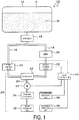
- FIG. 1 is a diagram illustrating a configuration of an aircraft water supply system 10 according to a first embodiment.
- the aircraft water supply system 10 supplies water to a water discharge port 12 in an aircraft.
- the water discharge port 12 is installed in a lavatory, a galley, or the like in an aircraft, for example, and provides users with water for hand washing or drinking.
- the water discharge port 12 is installed in a lavatory inside an aircraft.
- a hand wash faucet (the water discharge port 12 in the present embodiment) in a lavatory is used by an unspecified number of boarding passengers, and there are various demands for water temperature as compared with a faucet such as a galley used by a limited number of users.
- the discharge of the water from the water discharge port 12 is switched on/off by operating a discharge instruction unit 39.
- the discharge instruction unit 39 is a mechanism such as a sensor, a cock, a switch, or the like provided in the vicinity of the water discharge port 12.
- the discharge instruction unit 39 may be configured as an automatic faucet such that an infrared sensor is used as the discharge instruction unit 39, a user's hand is detected by the infrared sensor, and water is discharged when the user's hand is held over.
- the discharge instruction unit 39 may be configured as a manual faucet such that a cock or a switch is used as the discharge instruction unit 39 and water is discharged for a predetermined period in response to the user operating the cock or the switch.
- the temperature specifying unit 38 is disposed near the water discharge port 12, for example, and a user can specify the temperature of the water to be discharged from the water discharge port 12.
- the temperature specifying unit 38 may employ a button-based multi-stage switching system, a dial-based continuous switching system, or the like.
- the temperature specifying unit 38 may not be provided, and the water temperature may be maintained at a predetermined set temperature (fixed value).
- the water supplied to the water discharge port 12 is stored in a water tank 14 installed in an aircraft.
- the compressed air A is supplied to the water tank 14, and the water W is extruded toward the water discharge port 12 by the pressure from the compressed air A.
- the temperature of the water W inside the water tank 14 varies depending on the temperature and the like around the tank.
- the water flow path from the water tank 14 to the water discharge port 12 includes a cold water flow path 16, a hot water flow path 18, and a mixing flow path 24.
- a main valve (a shutoff valve) 15 is first provided downstream from the water tank 14.
- the main valve 15 is a valve for disconnecting the water tank 14 and the flow paths in the event of abnormalities.
- the cold water flow path 16 and the hot water flow path 18 are branched downstream from the main valve 15.
- cold water flow path 16 and the hot water flow path 18 may be connected directly to the water tank 14.
- main faucets a cold water faucet and a hot water faucet
- the cold water flow path 16 is a flow path for supplying cold water to the water discharge port 12, and is a flow path through which the water W in the water tank 14 flows as it is (without being heated).
- the cold water flow path 16 connects the water tank 14 and the mixing tank 22.
- the hot water flow path 18 is a flow path for supplying hot water to the water discharge port 12.
- the hot water flow path 18 connects the water tank 14 and the mixing tank 22.
- a water heater (WH) 20 is provided in the hot water flow path 18.
- a heating material is provided in the water heater 20, and water flowing through the hot water flow path 18 is heated by the water heater 20 to become hot water, and the hot water is supplied to the water discharge port 12.
- the temperature of the hot water heated by the water heater 20 varies depending on factors, for example, such as the temperature of the water W in the water tank 14, the heating performance of the water heater 20, the amount of continuous hot water used (the higher the continuous hot water usage, the lower the heating performance).
- the cold water flowing through the cold water flow path 16 and the hot water flowing through the hot water flow path 18 are mixed.
- the mixing flow path 24 connects the mixing tank 22 and the water discharge port 12, and the mixed water of cold water and hot water mixed in the mixing tank 22 flows through the mixing flow path 24.
- the components ranging from the mixing tank 22 to the mixing flow path 24 form a mixing supply unit 26.
- the mixing supply unit 26 mixes cold water and hot water downstream from the first control valve 30 and the second control valve 32, which will be described later, and supplies the mixed water to the water discharge port 12.
- the mixing flow path 24 is provided with a constant flow valve 34 that makes the amount of water supplied to the water discharge port 12 constant. As a result, the amount of the water discharged from the water discharge port 12 becomes constant.
- the constant flow valve 34 maintains the amount of water supplied to the downstream side to be constant by widening the water channel when the water pressure on the upstream side is low and narrowing the water channel when the water pressure on the upstream side is high.
- the temperature sensor 36 detects the water temperature at any point from the water tank 14 to the water discharge port 12.
- the temperature sensor 36 is provided in the mixing supply unit 26 to detect the water temperature in a state in which cold water flowing through the cold water flow path 16 and hot water flowing in the hot water flow path 18 are mixed.
- the temperature sensor 36 is provided downstream from the mixing tank 22 and on the mixing flow path 24 upstream from the constant flow valve 34, but the temperature sensor 36 may be provided, for example, in the mixing tank 22, or downstream from the constant flow valve 34.
- the detection value of the temperature sensor 36 is output to the flow control unit 40, which will be described later.
- the cold water flow path 16 and the hot water flow path 18 are each provided with a control valve for adjusting the flow rate of water flowing through each of the flow paths.
- a first control valve 30 that adjusts the flow rate of cold water flowing through the cold water flow path 16 and a second control valve 32 that adjusts the flow rate of hot water flowing through the hot water flow path 18 are provided.
- the first control valve 30 and the second control valve 32 are, for example, solenoid valves, and in the present embodiment, are proportional control valves of which the degree of valve opening depends on an input current value.
- the type of the valves used as the first control valve 30 and the second control valve 32 are not particularly limited as long as the flow rate of water flowing through each of the flow paths can be adjusted.
- the degree of valve opening can be adjusted arbitrarily (continuously), and the flow rate in each of the flow paths can be adjusted with higher accuracy.
- an ON-OFF valve of which the opening time (or closing time) per unit time can be adjusted by changing the duty ratio can be used.
- the flow control unit 40 controls the opening/closing state of the first control valve 30 and the second control valve 32 based on the water temperature detected by the temperature sensor 36.
- the temperature sensor 36 is provided in the mixing supply unit 26.
- the flow control unit 40 controls the opening/closing state of the first control valve 30 and the second control valve 32 based on the water temperature in the mixing supply unit 26.
- the flow control unit 40 controls the opening/closing state of the first control valve 30 and the second control valve 32 based on the temperature specified by the temperature specifying unit 38.
- the opening/closing state of each of the control valves 30 and 32 is controlled so that the temperature of the water discharged from the water discharge port 12 reaches the temperature specified by the temperature specifying unit 38 (hereinafter referred to as the "specified water temperature").
- the opening/closing state of the first control valve 30 and the second control valve 32 is controlled based on a predetermined set temperature (fixed value). In other words, the opening/closing state of each of the control valves 30 and 32 is controlled so that the temperature of the water discharged from the water discharge port 12 reaches a set temperature.
- the detection value of the temperature sensor 36 is approximately equal to the temperature of the water discharged from the water discharge port 12.
- the flow control unit 40 controls the first control valve 30 (the cold water side) to the opening direction and controls the second control valve 32 (the hot water side) to the closing direction so that the amount of the cold water flowing toward the mixing tank 22 is increased and the amount of the hot water flowing toward the mixing tank 22 is decreased.
- the flow control unit 40 controls the first control valve 30 (the cold water side) to the closing direction and controls the second control valve 32 (the hot water side) to the opening direction so that the amount of the cold water flowing toward the mixing tank 22 is decreased and the amount of the hot water flowing toward the mixing tank 22 is increased.
- the flow control unit 40 may adjust any one of the first control valve 30 and the second control valve 32 (the hot water side). For example, when the detection value of the temperature sensor 36 is higher than the specified water temperature, the first control valve 30 (the cold water side) may be controlled to the opening direction without changing the degree of opening of the second control valve 32 (the hot water side), and the second control valve 32 (the hot water side) may be controlled to the closing direction without changing the degree of opening of the first control valve 30 (the cold water side).
- the flow control unit 40 may control the opening/closing state of the first control valve 30 and the second control valve 32 so that the sum of the flow rate of the cold water flowing through the cold water flow path 16 and the flow rate of the hot water flowing through the water flow path 18 is substantially constant during the use of a hand wash faucet (that is, during the discharge of water from the water discharge port 12).
- the flow control unit 40 controls the opening/closing state of the first control valve 30 and the second control valve 32 so that the detection value of the temperature sensor 36 reaches a predetermined set temperature (fixed value).
- FIG. 2 is a flowchart illustrating processing of the flow control unit 40 in the first embodiment.
- the target degree of valve opening of the first control valve 30 and the second control valve 32 are each set to a predetermined initial setting value (step S200).
- step S202: Yes When a temperature specifying operation (change in the specified water temperature or the like) is performed on the temperature specifying unit 38 (step S202: Yes), the flow control unit 40 sets the target temperature of the water to be discharged from the water discharge port 12 to the specified water temperature (the temperature presently specified for the temperature specifying unit 38) (step S204). Additionally, when the specifying operation is not performed on the temperature specifying unit 38 (step S202: No), the target temperature is maintained at the current temperature setting (step S206).
- a temperature specifying operation change in the specified water temperature or the like
- step S208 No loop
- the flow control unit 40 opens the first control valve 30 and the second control valve 32 to the target degree of valve opening set in step S200, and starts passing water (step S208: Yes).
- the flow control unit 40 acquires the detection value of the temperature sensor 36 (step S210), and determines whether the current water temperature (current temperature) in the mixing supply unit 26 is within the range of target temperature ⁇ ⁇ ( ⁇ is a predetermined allowable value) (step S212).
- the flow control unit 40 changes the degrees of valve opening of the first control valve 30 and the second control valve 32 so that the water temperature in the mixing supply unit 26 approaches the target temperature (step S214). Specifically, for example, as described above, when the current temperature is higher than the target temperature, the first control valve 30 (the cold water side) is controlled to the opening direction and the second control valve 32 (the hot water side) is controlled to the closing direction. Further, for example, when the current temperature is lower than the target temperature, the first control valve 30 (the cold water side) is controlled to the closing direction, and the second control valve 32 (the hot water side) is controlled to the opening direction.
- step S212 When the current temperature is in the range of the target temperature ⁇ ⁇ (step S212: Yes), the flow control unit 40 maintains the degrees of valve opening of the first control valve 30 and the second control valve 32 in the current state (step S216).
- step S218 No loop
- the process returns to step S202 and the subsequent processing is continued. For example, when an operation of changing the specified water temperature is performed during the discharge of water, the target temperature is changed to the specified water temperature after change.
- the flow rate of cold water and hot water (the opening/closing state of the first control valve 30 and the second control valve 32) is controlled based on the water temperature detected by the temperature sensor 36, which is advantageous in controlling the temperature of the water to be discharged from the water discharge port 12 with high accuracy as compared with a case where the temperature sensor 36 is not used.
- the temperature sensor 36 is provided in the mixing supply unit 26, it is possible to detect the temperature of the mixed water of cold water and hot water (that is, the temperature of water in a state near the water to be discharged from the water discharge port 12), which is advantageous in adjusting the water temperature to the desired water temperature with high accuracy.
- the aircraft water supply system 10 controls the opening/closing state of the control valves 30 and 32 based on the temperature specified by the temperature specifying unit 38, which is advantageous in providing water at a temperature desired by the user.
- the aircraft water supply system 10 uses a proportional control valve as the first control valve 30 and the second control valve 32, which is advantageous in adjusting the flow rates of cold water and hot water with high accuracy.
- the temperature sensor 36 is provided in the mixing supply unit 26.
- the temperature sensor 36 is provided in the cold water flow path 16 and the hot water flow path 18.
- FIG. 3 is a diagram illustrating a configuration of an aircraft water supply system 50 according to a second embodiment.
- the temperature sensors 36 are provided in the cold water flow path 16 and the hot water flow path 18, respectively.
- the temperature sensor provided in the cold water flow path 16 is referred to as a temperature sensor 36A
- a temperature sensor provided in the hot water flow path 18 is referred to as a temperature sensor 36B.
- the temperature sensor 36A is provided in the water flow path 16 downstream from the water tank 14 and upstream from the first control valve 30, and the temperature sensor 36B is provided in the hot water flow path 18 at a location downstream from the water heater 20 and upstream from the second control valve 32.
- the flow control unit 40 acquires the detection values of the temperature sensor 36A and the temperature sensor 36B, and controls the opening/closing state of the first control valve 30 and the second control valve 32 based on the temperature of the cold water flowing through the cold water flow path 16 and the temperature of the hot water flowing through the hot water flow path 18.
- the flow control unit 40 controls the mixing ratio ( ⁇ the degree of valve opening) of the cold water and the hot water based on the temperatures of the cold water and the hot water acquired from the temperature sensors 36A and 36B so that the mixed water of cold water and hot water is at a target temperature.
- the flow control unit 40 may adjust the change in temperature of the cold water and hot water downstream from the temperature sensors 36A and 36B, for example, based on the thermal conductivity of the material of components (for example, the mixing tank 22 and the mixing flow path 24) downstream from the temperature sensors 36A and 36B or the temperature or the like around the components and control the opening/closing state of the first control valve 30 and the second control valve 32 by taking the predicted change in temperature into consideration.
- the material of components for example, the mixing tank 22 and the mixing flow path 24
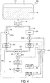
- a temperature sensor 36C may be provided in the mixing supply unit 26 in addition to the temperature sensors 36A and 36B.
- the flow control unit 40 controls the opening/closing state of the first control valve 30 and the second control valve 32 based on the temperature of the cold water flowing through the cold water flow path 16, the temperature of the hot water flowing through the hot water flow path 18, and the water temperature in the mixing supply unit 26.
- the flow control unit 40 determines a degree of valve opening changing direction based on the temperature of the mixed water acquired from the temperature sensor 36C so that the mixed water of cold water and hot water is at a target temperature. Furthermore, the flow control unit 40 determines the amount of change in the degree of valve opening based on the temperatures of the cold water and the hot water obtained from the temperature sensors 36A and 36B. Thus, for example, when the detection value of the temperature sensor 36C is higher than the target temperature, the flow control unit 40 determines that the first control valve 30 (the cold water side) is controlled to the opening direction and the second control valve 32 (the hot water side) is controlled to the closing direction. Specifically, how much the valve opening is to be changed is determined based on the temperatures of cold water and hot water acquired from the temperature sensors 36A and 36B.
- the temperature of the water discharged from the water discharge port 12 can be brought closer to the target temperature with higher accuracy.
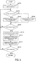
- FIG. 5 is a flowchart illustrating processing of the flow control unit 40 in the second embodiment (the case of the configuration illustrated in FIG. 3 ).
- the target degrees of valve opening of the first control valve 30 and the second control valve 32 are each set to a predetermined initial setting value (step S500).
- step S504 When a temperature specifying operation (change in the specified water temperature or the like) is performed on the temperature specifying unit 38 (step S504: Yes), the flow control unit 40 sets the target temperature of the water to be discharged from the water discharge port 12 to the specified water temperature (the temperature presently specified for the temperature specifying unit 38) (step S506). Additionally, when the specifying operation is not performed on the temperature specifying unit 38 (step S504: No), the target temperature is maintained at the current temperature setting (step S508).
- a temperature specifying operation change in the specified water temperature or the like
- step S509 No loop
- the flow control unit 40 opens the first control valve 30 and the second control valve 32 to the target degrees of valve opening set in step S200, and starts passing water (step S509: Yes).
- the flow control unit 40 acquires the detection values of the temperature sensors 36A and 36B (step S510), and determines the target degrees of valve opening of the first control valve 30 and the second control valve 32 based on the cold water temperature and the hot water temperature acquired from the temperature sensors 36A and 36B, and the target temperature (step S512). Specifically, the mixing ratio of cold water and hot water is calculated such that the mixed water of cold water and hot water is at a target temperature, and the degree of valve opening is calculated such that cold water and hot water flowing on the mixing supply unit 26 side have the mixing ratio.
- the degrees of valve opening of the first control valve 30 and the second control valve 32 are changed to match the target degrees of valve opening (step S514).
- step S516 No loop
- the process returns to step S504 and the subsequent processing is continued.
- the target temperature is changed to the specified water temperature after change.
- the temperature sensors 36A and 36B are provided in the cold water flow path 16 and the hot water flow path 18, respectively, which is advantageous in adjusting the mixing ratio at the stage of mixing cold water and hot water and adjusting the temperature of the water to be discharged from the water discharge port 12 to a desired water temperature.
- the temperature sensors 36A, 36B, and 36C are provided in the mixing supply unit 26 as well as in the cold water flow path 16 and the hot water flow path 18 as illustrated in FIG. 4 , which is advantageous in adjusting the temperature of the water to be discharged from the water discharge port 12 with higher accuracy.
Landscapes
- Engineering & Computer Science (AREA)
- Physics & Mathematics (AREA)
- General Engineering & Computer Science (AREA)
- Chemical & Material Sciences (AREA)
- Combustion & Propulsion (AREA)
- Mechanical Engineering (AREA)
- Thermal Sciences (AREA)
- Aviation & Aerospace Engineering (AREA)
- Fluid Mechanics (AREA)
- General Physics & Mathematics (AREA)
- Automation & Control Theory (AREA)
- Domestic Hot-Water Supply Systems And Details Of Heating Systems (AREA)
- Control Of Non-Electrical Variables (AREA)
- Control Of Temperature (AREA)
- Multiple-Way Valves (AREA)
Abstract
Description
- The present invention relates to an aircraft water supply system for supplying water to a water discharge port in an aircraft.
- In the related art, two lines, one for cold water and the other for hot water, are connected to a water discharge port provided in a lavatory or the like in an aircraft, and it is possible to switch the temperature or adjust the temperature to an intermediate temperature according to the user's preference.
- As a method for adjusting the temperature to an intermediate temperature, a manual (dial) type has been adopted in the old model, and a button-based multi-stage (for example, 5-step) switching method and the like have been adopted recently.
- Most of the button-based multi-step methods are electronically controlled, and for example, a method of changing the actual flow rate ratio by changing the duty ratio of a solenoid valve (ON-OFF valve) between hot water and cold water has been proposed.
- For example, in
Patent Document 1 described below, a mixing means is provided with a first solenoid valve and a second solenoid valve individually connected to a cold water inlet port and a hot water inlet port, a control signal reflecting the temperature specified by a temperature adjusting means is transmitted to the mixing means via a control wire, and a duty ratio of each of the first solenoid valve and the second solenoid valve is changed based on the specified temperature, whereby the water temperature of the mixed water is adjusted. - Patent Document 1:
JP 4457139 B - However, temperature of both cold water and hot water is not constant due to environmental factors within aircrafts (for example, flight altitude (outside air temperature), heater performance for hot water, continuous hot water usage, and the like). Thus, even if cold water and hot water are mixed by controlling the electromagnetic valve according to the conventional method, the temperature of the water supplied to a water discharge port will not be constant. In other words, even when the temperature is set by a user, the relative water temperature can be adjusted, but there is a problem that it is difficult to supply water at a certain temperature.
- In light of the foregoing, an object of the present invention is to enable water to be used in an aircraft to be supplied at a desired temperature.
- In order to attain the object, the present invention provides an aircraft water supply system for supplying water to a water discharge port in an aircraft, the system including: a cold water flow path that supplies cold water to the water discharge port; a hot water flow path that supplies hot water to the water discharge port; a first control valve that adjusts a flow rate of the cold water flowing through the cold water flow path; a second control valve that adjusts a flow rate of the hot water flowing through the hot water flow path; a temperature sensor that detects a water temperature at any point up to the water discharge port; and a flow control unit that controls an opening/closing state of the first control valve and the second control valve based on the water temperature detected by the temperature sensor.
- According to the present invention, since the flow rate of cold water and hot water (the opening/closing state of the first control valve and the second control valve) is controlled based on the water temperature detected by the temperature sensor, which is advantageous in controlling the temperature of the water to be discharged from the water discharge port with high accuracy as compared with a case where the temperature sensor is not used.
-
-
FIG. 1 is a diagram illustrating a configuration of an aircraftwater supply system 10 according to a first embodiment. -
FIG. 2 is a flowchart illustrating processing of aflow control unit 40 in the first embodiment. -
FIG. 3 is a diagram illustrating a configuration of an aircraftwater supply system 50 according to a second embodiment. -
FIG. 4 is a diagram illustrating another configuration of an aircraftwater supply system 50 according to the second embodiment. -
FIG. 5 is a flowchart illustrating processing of theflow control unit 40 in the second embodiment. - Aircraft water supply systems according to preferred embodiments of the present invention are described in detail below with reference to the accompanying drawings.
-
FIG. 1 is a diagram illustrating a configuration of an aircraftwater supply system 10 according to a first embodiment. - The aircraft
water supply system 10 supplies water to awater discharge port 12 in an aircraft. Thewater discharge port 12 is installed in a lavatory, a galley, or the like in an aircraft, for example, and provides users with water for hand washing or drinking. - In the present embodiment, it is assumed that the
water discharge port 12 is installed in a lavatory inside an aircraft. A hand wash faucet (thewater discharge port 12 in the present embodiment) in a lavatory is used by an unspecified number of boarding passengers, and there are various demands for water temperature as compared with a faucet such as a galley used by a limited number of users. - The discharge of the water from the
water discharge port 12 is switched on/off by operating adischarge instruction unit 39. Thedischarge instruction unit 39 is a mechanism such as a sensor, a cock, a switch, or the like provided in the vicinity of thewater discharge port 12. For example, thedischarge instruction unit 39 may be configured as an automatic faucet such that an infrared sensor is used as thedischarge instruction unit 39, a user's hand is detected by the infrared sensor, and water is discharged when the user's hand is held over. Alternatively, thedischarge instruction unit 39 may be configured as a manual faucet such that a cock or a switch is used as thedischarge instruction unit 39 and water is discharged for a predetermined period in response to the user operating the cock or the switch. - The
temperature specifying unit 38 is disposed near thewater discharge port 12, for example, and a user can specify the temperature of the water to be discharged from thewater discharge port 12. Thetemperature specifying unit 38 may employ a button-based multi-stage switching system, a dial-based continuous switching system, or the like. - Note that the
temperature specifying unit 38 may not be provided, and the water temperature may be maintained at a predetermined set temperature (fixed value). - The water supplied to the
water discharge port 12 is stored in awater tank 14 installed in an aircraft. In addition to the water W, the compressed air A is supplied to thewater tank 14, and the water W is extruded toward thewater discharge port 12 by the pressure from the compressed air A. The temperature of the water W inside thewater tank 14 varies depending on the temperature and the like around the tank. - The water flow path from the
water tank 14 to thewater discharge port 12 includes a coldwater flow path 16, a hotwater flow path 18, and amixing flow path 24. In the present embodiment, a main valve (a shutoff valve) 15 is first provided downstream from thewater tank 14. Themain valve 15 is a valve for disconnecting thewater tank 14 and the flow paths in the event of abnormalities. The coldwater flow path 16 and the hotwater flow path 18 are branched downstream from themain valve 15. - Note that the cold
water flow path 16 and the hotwater flow path 18 may be connected directly to thewater tank 14. In this case, main faucets (a cold water faucet and a hot water faucet) may be provided at positions near thewater tank 14 of the coldwater flow path 16 and the hotwater flow path 18, respectively. - The cold
water flow path 16 is a flow path for supplying cold water to thewater discharge port 12, and is a flow path through which the water W in thewater tank 14 flows as it is (without being heated). In the present embodiment, the coldwater flow path 16 connects thewater tank 14 and themixing tank 22. - The hot
water flow path 18 is a flow path for supplying hot water to thewater discharge port 12. In the present embodiment, the hotwater flow path 18 connects thewater tank 14 and themixing tank 22. A water heater (WH) 20 is provided in the hotwater flow path 18. A heating material is provided in thewater heater 20, and water flowing through the hotwater flow path 18 is heated by thewater heater 20 to become hot water, and the hot water is supplied to thewater discharge port 12. The temperature of the hot water heated by thewater heater 20 varies depending on factors, for example, such as the temperature of the water W in thewater tank 14, the heating performance of thewater heater 20, the amount of continuous hot water used (the higher the continuous hot water usage, the lower the heating performance). - In the
mixing tank 22, the cold water flowing through the coldwater flow path 16 and the hot water flowing through the hotwater flow path 18 are mixed. - The
mixing flow path 24 connects themixing tank 22 and thewater discharge port 12, and the mixed water of cold water and hot water mixed in themixing tank 22 flows through themixing flow path 24. - In the present embodiment, the components ranging from the
mixing tank 22 to themixing flow path 24 form amixing supply unit 26. Themixing supply unit 26 mixes cold water and hot water downstream from thefirst control valve 30 and thesecond control valve 32, which will be described later, and supplies the mixed water to thewater discharge port 12. - The
mixing flow path 24 is provided with aconstant flow valve 34 that makes the amount of water supplied to thewater discharge port 12 constant. As a result, the amount of the water discharged from thewater discharge port 12 becomes constant. Theconstant flow valve 34 maintains the amount of water supplied to the downstream side to be constant by widening the water channel when the water pressure on the upstream side is low and narrowing the water channel when the water pressure on the upstream side is high. - In this case, the
temperature sensor 36 detects the water temperature at any point from thewater tank 14 to thewater discharge port 12. In the first embodiment, thetemperature sensor 36 is provided in themixing supply unit 26 to detect the water temperature in a state in which cold water flowing through the coldwater flow path 16 and hot water flowing in the hotwater flow path 18 are mixed. InFIG. 1 , thetemperature sensor 36 is provided downstream from themixing tank 22 and on themixing flow path 24 upstream from theconstant flow valve 34, but thetemperature sensor 36 may be provided, for example, in themixing tank 22, or downstream from theconstant flow valve 34. - The detection value of the
temperature sensor 36 is output to theflow control unit 40, which will be described later. - The cold
water flow path 16 and the hotwater flow path 18 are each provided with a control valve for adjusting the flow rate of water flowing through each of the flow paths. - That is, a
first control valve 30 that adjusts the flow rate of cold water flowing through the coldwater flow path 16 and asecond control valve 32 that adjusts the flow rate of hot water flowing through the hotwater flow path 18 are provided. - The
first control valve 30 and thesecond control valve 32 are, for example, solenoid valves, and in the present embodiment, are proportional control valves of which the degree of valve opening depends on an input current value. - The type of the valves used as the
first control valve 30 and thesecond control valve 32 are not particularly limited as long as the flow rate of water flowing through each of the flow paths can be adjusted. When a proportional control valve is used, the degree of valve opening can be adjusted arbitrarily (continuously), and the flow rate in each of the flow paths can be adjusted with higher accuracy. - As another example of the valves used as the
first control valve 30 and thesecond control valve 32, an ON-OFF valve of which the opening time (or closing time) per unit time can be adjusted by changing the duty ratio can be used. - The flow control unit 40 (controller) controls the opening/closing state of the
first control valve 30 and thesecond control valve 32 based on the water temperature detected by thetemperature sensor 36. In the present embodiment, thetemperature sensor 36 is provided in the mixingsupply unit 26. In this case, theflow control unit 40 controls the opening/closing state of thefirst control valve 30 and thesecond control valve 32 based on the water temperature in the mixingsupply unit 26. - The
flow control unit 40 controls the opening/closing state of thefirst control valve 30 and thesecond control valve 32 based on the temperature specified by thetemperature specifying unit 38. In other words, the opening/closing state of each of thecontrol valves water discharge port 12 reaches the temperature specified by the temperature specifying unit 38 (hereinafter referred to as the "specified water temperature"). - Note that when the
temperature specifying unit 38 is not provided, the opening/closing state of thefirst control valve 30 and thesecond control valve 32 is controlled based on a predetermined set temperature (fixed value). In other words, the opening/closing state of each of thecontrol valves water discharge port 12 reaches a set temperature. - In the present embodiment, since the
temperature sensor 36 is provided in the mixingsupply unit 26, the detection value of thetemperature sensor 36 is approximately equal to the temperature of the water discharged from thewater discharge port 12. Thus, for example, when the detection value of thetemperature sensor 36 is higher than the specified water temperature, theflow control unit 40 controls the first control valve 30 (the cold water side) to the opening direction and controls the second control valve 32 (the hot water side) to the closing direction so that the amount of the cold water flowing toward the mixingtank 22 is increased and the amount of the hot water flowing toward the mixingtank 22 is decreased. Further, for example, when the detection value of thetemperature sensor 36 is lower than the specified water temperature, theflow control unit 40 controls the first control valve 30 (the cold water side) to the closing direction and controls the second control valve 32 (the hot water side) to the opening direction so that the amount of the cold water flowing toward the mixingtank 22 is decreased and the amount of the hot water flowing toward the mixingtank 22 is increased. - Note that the
flow control unit 40 may adjust any one of thefirst control valve 30 and the second control valve 32 (the hot water side). For example, when the detection value of thetemperature sensor 36 is higher than the specified water temperature, the first control valve 30 (the cold water side) may be controlled to the opening direction without changing the degree of opening of the second control valve 32 (the hot water side), and the second control valve 32 (the hot water side) may be controlled to the closing direction without changing the degree of opening of the first control valve 30 (the cold water side). - On the other hand, when only one of the
first control valve 30 and thesecond control valve 32 is adjusted, there is a possibility that the amount of water supplied to the mixingsupply unit 26 fluctuates. Thus, theflow control unit 40 may control the opening/closing state of thefirst control valve 30 and thesecond control valve 32 so that the sum of the flow rate of the cold water flowing through the coldwater flow path 16 and the flow rate of the hot water flowing through thewater flow path 18 is substantially constant during the use of a hand wash faucet (that is, during the discharge of water from the water discharge port 12). - When the
temperature specifying unit 38 is not provided, theflow control unit 40 controls the opening/closing state of thefirst control valve 30 and thesecond control valve 32 so that the detection value of thetemperature sensor 36 reaches a predetermined set temperature (fixed value). -
FIG. 2 is a flowchart illustrating processing of theflow control unit 40 in the first embodiment. - In an initial state, the target degree of valve opening of the
first control valve 30 and thesecond control valve 32 are each set to a predetermined initial setting value (step S200). - When a temperature specifying operation (change in the specified water temperature or the like) is performed on the temperature specifying unit 38 (step S202: Yes), the
flow control unit 40 sets the target temperature of the water to be discharged from thewater discharge port 12 to the specified water temperature (the temperature presently specified for the temperature specifying unit 38) (step S204). Additionally, when the specifying operation is not performed on the temperature specifying unit 38 (step S202: No), the target temperature is maintained at the current temperature setting (step S206). - Until an operation (discharge ON operation) is performed on the
discharge instruction unit 39 and passing of water is performed (step S208: No loop), the process returns to step S202 and the subsequent processing is continued. - When an operation (discharge ON operation) is performed on the
discharge instruction unit 39, theflow control unit 40 opens thefirst control valve 30 and thesecond control valve 32 to the target degree of valve opening set in step S200, and starts passing water (step S208: Yes). - The
flow control unit 40 acquires the detection value of the temperature sensor 36 (step S210), and determines whether the current water temperature (current temperature) in the mixingsupply unit 26 is within the range of target temperature ± α (α is a predetermined allowable value) (step S212). - When the current temperature is not in the range of target temperature ± α (step S212: No), the
flow control unit 40 changes the degrees of valve opening of thefirst control valve 30 and thesecond control valve 32 so that the water temperature in the mixingsupply unit 26 approaches the target temperature (step S214). Specifically, for example, as described above, when the current temperature is higher than the target temperature, the first control valve 30 (the cold water side) is controlled to the opening direction and the second control valve 32 (the hot water side) is controlled to the closing direction. Further, for example, when the current temperature is lower than the target temperature, the first control valve 30 (the cold water side) is controlled to the closing direction, and the second control valve 32 (the hot water side) is controlled to the opening direction. - When the current temperature is in the range of the target temperature ± α (step S212: Yes), the
flow control unit 40 maintains the degrees of valve opening of thefirst control valve 30 and thesecond control valve 32 in the current state (step S216). - Until an operation (discharge OFF operation) is performed on the
discharge instruction unit 39 and passing of water ends (step S218: No loop), the process returns to step S202 and the subsequent processing is continued. For example, when an operation of changing the specified water temperature is performed during the discharge of water, the target temperature is changed to the specified water temperature after change. - Then, when an operation (discharge OFF operation) is performed on the
discharge instruction unit 39, thefirst control valve 30 and thesecond control valve 32 are fully closed to end passing of water (step S218: Yes), and the processing of this flowchart ends. - As described above, in the aircraft
water supply system 10 according to the first embodiment, since the flow rate of cold water and hot water (the opening/closing state of thefirst control valve 30 and the second control valve 32) is controlled based on the water temperature detected by thetemperature sensor 36, which is advantageous in controlling the temperature of the water to be discharged from thewater discharge port 12 with high accuracy as compared with a case where thetemperature sensor 36 is not used. - In addition, in the aircraft
water supply system 10, since thetemperature sensor 36 is provided in the mixingsupply unit 26, it is possible to detect the temperature of the mixed water of cold water and hot water (that is, the temperature of water in a state near the water to be discharged from the water discharge port 12), which is advantageous in adjusting the water temperature to the desired water temperature with high accuracy. - Furthermore, the aircraft
water supply system 10 controls the opening/closing state of thecontrol valves temperature specifying unit 38, which is advantageous in providing water at a temperature desired by the user. - Furthermore, the aircraft
water supply system 10 uses a proportional control valve as thefirst control valve 30 and thesecond control valve 32, which is advantageous in adjusting the flow rates of cold water and hot water with high accuracy. - In the first embodiment, the
temperature sensor 36 is provided in the mixingsupply unit 26. In the second embodiment, a case in which thetemperature sensor 36 is provided in the coldwater flow path 16 and the hotwater flow path 18 will be described. -
FIG. 3 is a diagram illustrating a configuration of an aircraftwater supply system 50 according to a second embodiment. - In the configuration illustrated in
FIG. 3 , the same parts as those inFIG. 1 are denoted by the same reference signs, and detailed description thereof will be omitted. - In the aircraft
water supply system 50 according to the second embodiment, the temperature sensors 36 (36A, 36B) are provided in the coldwater flow path 16 and the hotwater flow path 18, respectively. The temperature sensor provided in the coldwater flow path 16 is referred to as atemperature sensor 36A, and a temperature sensor provided in the hotwater flow path 18 is referred to as atemperature sensor 36B. - Note that in the example of
FIG. 3 , thetemperature sensor 36A is provided in thewater flow path 16 downstream from thewater tank 14 and upstream from thefirst control valve 30, and thetemperature sensor 36B is provided in the hotwater flow path 18 at a location downstream from thewater heater 20 and upstream from thesecond control valve 32. - The
flow control unit 40 acquires the detection values of thetemperature sensor 36A and thetemperature sensor 36B, and controls the opening/closing state of thefirst control valve 30 and thesecond control valve 32 based on the temperature of the cold water flowing through the coldwater flow path 16 and the temperature of the hot water flowing through the hotwater flow path 18. - That is, the temperature of the mixed water when a plurality of components of water having different temperatures are mixed by a predetermined amount can be predicted with a certain accuracy. Thus, the
flow control unit 40 controls the mixing ratio (≈ the degree of valve opening) of the cold water and the hot water based on the temperatures of the cold water and the hot water acquired from thetemperature sensors - Note that the
flow control unit 40 may adjust the change in temperature of the cold water and hot water downstream from thetemperature sensors tank 22 and the mixing flow path 24) downstream from thetemperature sensors first control valve 30 and thesecond control valve 32 by taking the predicted change in temperature into consideration. - Furthermore, as illustrated in
FIG. 4 for example, atemperature sensor 36C may be provided in the mixingsupply unit 26 in addition to thetemperature sensors flow control unit 40 controls the opening/closing state of thefirst control valve 30 and thesecond control valve 32 based on the temperature of the cold water flowing through the coldwater flow path 16, the temperature of the hot water flowing through the hotwater flow path 18, and the water temperature in the mixingsupply unit 26. - For example, the
flow control unit 40 determines a degree of valve opening changing direction based on the temperature of the mixed water acquired from thetemperature sensor 36C so that the mixed water of cold water and hot water is at a target temperature. Furthermore, theflow control unit 40 determines the amount of change in the degree of valve opening based on the temperatures of the cold water and the hot water obtained from thetemperature sensors temperature sensor 36C is higher than the target temperature, theflow control unit 40 determines that the first control valve 30 (the cold water side) is controlled to the opening direction and the second control valve 32 (the hot water side) is controlled to the closing direction. Specifically, how much the valve opening is to be changed is determined based on the temperatures of cold water and hot water acquired from thetemperature sensors - In this way, by using three
temperature sensors 36, the temperature of the water discharged from thewater discharge port 12 can be brought closer to the target temperature with higher accuracy. -
FIG. 5 is a flowchart illustrating processing of theflow control unit 40 in the second embodiment (the case of the configuration illustrated inFIG. 3 ). - In an initial state, the target degrees of valve opening of the
first control valve 30 and thesecond control valve 32 are each set to a predetermined initial setting value (step S500). - When a temperature specifying operation (change in the specified water temperature or the like) is performed on the temperature specifying unit 38 (step S504: Yes), the
flow control unit 40 sets the target temperature of the water to be discharged from thewater discharge port 12 to the specified water temperature (the temperature presently specified for the temperature specifying unit 38) (step S506). Additionally, when the specifying operation is not performed on the temperature specifying unit 38 (step S504: No), the target temperature is maintained at the current temperature setting (step S508). - Until an operation (discharge ON operation) is performed on the
discharge instruction unit 39 and passing of water is performed (step S509: No loop), the process returns to step S504 and the subsequent processing is continued. - When an operation (discharge ON operation) is performed on the
discharge instruction unit 39, theflow control unit 40 opens thefirst control valve 30 and thesecond control valve 32 to the target degrees of valve opening set in step S200, and starts passing water (step S509: Yes). - The
flow control unit 40 acquires the detection values of thetemperature sensors first control valve 30 and thesecond control valve 32 based on the cold water temperature and the hot water temperature acquired from thetemperature sensors supply unit 26 side have the mixing ratio. - Then, the degrees of valve opening of the
first control valve 30 and thesecond control valve 32 are changed to match the target degrees of valve opening (step S514). - Until an operation (discharge OFF operation) is performed on the
discharge instruction unit 39 and passing of water ends (step S516: No loop), the process returns to step S504 and the subsequent processing is continued. For example, when an operation of changing the specified water temperature is performed during the discharge of water, the target temperature is changed to the specified water temperature after change. - Then, when an operation (discharge OFF operation) is performed on the
discharge instruction unit 39, thefirst control valve 30 and thesecond control valve 32 are fully closed to end passing of water (step S516: Yes), and the processing of this flowchart ends. - As described above, according to the aircraft
water supply system 50 according to the second embodiment, the following effects can be obtained in addition to the effects of the first embodiment. - In other words, in the aircraft
water supply system 50, thetemperature sensors water flow path 16 and the hotwater flow path 18, respectively, which is advantageous in adjusting the mixing ratio at the stage of mixing cold water and hot water and adjusting the temperature of the water to be discharged from thewater discharge port 12 to a desired water temperature. - In addition, the
temperature sensors supply unit 26 as well as in the coldwater flow path 16 and the hotwater flow path 18 as illustrated inFIG. 4 , which is advantageous in adjusting the temperature of the water to be discharged from thewater discharge port 12 with higher accuracy. -
- 10, 50 Aircraft water supply system
- 12 Water discharge port
- 14 Water tank
- 16 Cold water flow path
- 18 Hot water flow path
- 20 Water heater
- 22 Mixing tank
- 24 Mixing flow path
- 26 Mixing supply unit
- 30 First control valve
- 32 Second control valve
- 34 Constant flow valve
- 36 (36A, 36B, 36C) Temperature sensor
- 38 Temperature specifying unit
- 39 Discharge instruction unit
- 40 Flow control unit
- A Compressed air
- W Water
Claims (8)
- An aircraft water supply system for supplying water to a water discharge port in an aircraft, the system comprising:a cold water flow path that supplies cold water to the water discharge port;a hot water flow path that supplies hot water to the water discharge port;a first control valve that adjusts a flow rate of the cold water flowing through the cold water flow path;a second control valve that adjusts a flow rate of the hot water flowing through the hot water flow path;a temperature sensor that detects a water temperature at any point up to the water discharge port; anda flow control unit that controls an opening/closing state of the first control valve and the second control valve based on the water temperature detected by the temperature sensor.
- The aircraft water supply system according to claim 1, further comprising a mixing supply unit that mixes the cold water and the hot water downstream from the first control valve and the second control valve and supplies mixed water to the water discharge port, wherein
the mixing supply unit comprises the temperature sensor, and
the flow control unit controls the opening/closing state of the first control valve and the second control valve based on the water temperature in the mixing supply unit. - The aircraft water supply system according to claim 1, wherein
the cold water flow path and the hot water flow path each comprise the temperature sensor, and
the flow control unit controls the opening/closing state of the first control valve and the second control valve based on a temperature of the cold water flowing through the cold water flow path and a temperature of the hot water flowing through the hot water flow path. - The aircraft water supply system according to claim 3, further comprising a mixing supply unit that mixes the cold water and the hot water downstream from the first control valve and the second control valve and supplies the mixed water to the water discharge port, wherein
the mixing supply unit further comprises the temperature sensor, and
the flow control unit controls the opening/closing state of the first control valve and the second control valve based on a temperature of the cold water flowing through the cold water flow path, a temperature of the hot water flowing through the hot water flow path, and the water temperature in the mixing supply unit. - The aircraft water supply system according to claim 3, wherein the flow control unit predicts a change in temperature of the cold water and the hot water downstream from the temperature sensor based on at least one of a thermal conductivity of a component downstream from the temperature sensor or a temperature around the component, and controls the opening/closing state of the first control valve and the second control valve by taking the change in temperature into consideration.
- The aircraft water supply system according to claim 1, further comprising a temperature specifying unit that allows a user to specify a temperature of the water to be discharged from the water discharge port, wherein the flow control unit controls the opening/closing state of the first control valve and the second control valve based on the temperature specified by the temperature specifying unit.
- The aircraft water supply system according to any one of claims 1 to 6, wherein the flow control unit controls the opening/closing state of the first control valve and the second control valve so that a sum of the flow rate of the cold water flowing through the cold water flow path and the flow rate of the hot water flowing through the hot water flow path is approximately constant during discharge of water from the water discharge port.
- The aircraft water supply system according to any one of claims 1 to 7, wherein the first control valve and the second control valve are proportional control valves, whose degree of openings can be adjusted as desired.
Applications Claiming Priority (2)
| Application Number | Priority Date | Filing Date | Title |
|---|---|---|---|
| JP2018173755A JP7070267B2 (en) | 2018-09-18 | 2018-09-18 | Aircraft hot water supply system |
| PCT/JP2019/036103 WO2020059659A1 (en) | 2018-09-18 | 2019-09-13 | Hot and cold water supply system for aircraft |
Publications (3)
| Publication Number | Publication Date |
|---|---|
| EP3855278A1 true EP3855278A1 (en) | 2021-07-28 |
| EP3855278A4 EP3855278A4 (en) | 2022-06-08 |
| EP3855278B1 EP3855278B1 (en) | 2025-07-30 |
Family
ID=69887380
Family Applications (1)
| Application Number | Title | Priority Date | Filing Date |
|---|---|---|---|
| EP19861513.0A Active EP3855278B1 (en) | 2018-09-18 | 2019-09-13 | Hot and cold water supply system for aircraft |
Country Status (4)
| Country | Link |
|---|---|
| US (1) | US12037119B2 (en) |
| EP (1) | EP3855278B1 (en) |
| JP (1) | JP7070267B2 (en) |
| WO (1) | WO2020059659A1 (en) |
Cited By (1)
| Publication number | Priority date | Publication date | Assignee | Title |
|---|---|---|---|---|
| US20250059742A1 (en) * | 2023-02-16 | 2025-02-20 | Bisource Hardware Manufacturing Co., Ltd. | Faucet water discharge control method, faucet water discharge control system, and storage medium |
Families Citing this family (2)
| Publication number | Priority date | Publication date | Assignee | Title |
|---|---|---|---|---|
| CN117658249B (en) * | 2023-11-20 | 2026-03-10 | 九阳股份有限公司 | Temperature flow control method for water purifier and water purifier |
| CN120740140B (en) * | 2025-08-20 | 2025-11-21 | 城信科技股份有限公司 | Smart City Intelligent Information Construction System and Methods |
Family Cites Families (12)
| Publication number | Priority date | Publication date | Assignee | Title |
|---|---|---|---|---|
| US3952796A (en) * | 1975-04-07 | 1976-04-27 | Larson Richard C | Temperature control system |
| JP3025395B2 (en) * | 1993-07-12 | 2000-03-27 | 株式会社山武 | Flow control valve device |
| JP3277650B2 (en) | 1993-10-29 | 2002-04-22 | 株式会社ノーリツ | Hot water supply control device |
| JP4345134B2 (en) * | 1999-05-26 | 2009-10-14 | パナソニック株式会社 | Hot water supply device and hot water cleaning device |
| JP3466598B2 (en) * | 2002-04-18 | 2003-11-10 | 株式会社アルボ | Control device in fluid mixing device |
| US7520445B2 (en) * | 2004-05-22 | 2009-04-21 | David A. Feinleib | Method, apparatus, and system for projecting hot water availability for showering and bathing |
| US7584898B2 (en) * | 2005-07-01 | 2009-09-08 | Masco Corporation Of Indiana | Manual override for electronic proportioning valve |
| KR20060120544A (en) * | 2006-11-06 | 2006-11-27 | 신기빈 | Cold and hot water piping system using one supply pipe |
| JP4457139B2 (en) | 2007-10-01 | 2010-04-28 | 株式会社ジャムコ | Air and water mixing system for aircraft |
| DE102009013558B4 (en) * | 2009-03-17 | 2016-02-18 | Airbus Operations Gmbh | Combined Bidet Toilet Construction for Aircraft |
| US9316412B2 (en) | 2014-04-25 | 2016-04-19 | Goodrich Corporation | High capacity water heater |
| JP7003885B2 (en) * | 2018-09-18 | 2022-02-04 | 横浜ゴム株式会社 | Aircraft hot water supply system |
-
2018
- 2018-09-18 JP JP2018173755A patent/JP7070267B2/en not_active Expired - Fee Related
-
2019
- 2019-09-13 US US17/275,879 patent/US12037119B2/en active Active
- 2019-09-13 WO PCT/JP2019/036103 patent/WO2020059659A1/en not_active Ceased
- 2019-09-13 EP EP19861513.0A patent/EP3855278B1/en active Active
Cited By (1)
| Publication number | Priority date | Publication date | Assignee | Title |
|---|---|---|---|---|
| US20250059742A1 (en) * | 2023-02-16 | 2025-02-20 | Bisource Hardware Manufacturing Co., Ltd. | Faucet water discharge control method, faucet water discharge control system, and storage medium |
Also Published As
| Publication number | Publication date |
|---|---|
| EP3855278A4 (en) | 2022-06-08 |
| JP7070267B2 (en) | 2022-05-18 |
| US12037119B2 (en) | 2024-07-16 |
| WO2020059659A1 (en) | 2020-03-26 |
| JP2020046830A (en) | 2020-03-26 |
| EP3855278B1 (en) | 2025-07-30 |
| US20220055753A1 (en) | 2022-02-24 |
Similar Documents
| Publication | Publication Date | Title |
|---|---|---|
| EP3855279B1 (en) | Hot and cold water supply system for aircraft | |
| EP3855278B1 (en) | Hot and cold water supply system for aircraft | |
| EP3106764B1 (en) | Hot and cold water mixing device | |
| US11149965B2 (en) | Water heating system including multi-function heat source apparatus | |
| CN105706006B (en) | Diagnostic method for the correct function of diagnosing heat supply and/or cooling system | |
| US9122284B2 (en) | Electromechanical temperature regulation system for providing tempered mix water | |
| EP3564593A3 (en) | Thermostatic device and sanitary water supply and/or dispensing system comprising such a thermostatic device | |
| RU2508510C1 (en) | Fluid distribution control system | |
| EP2587171B1 (en) | Method of controlling a variable delivery pump fitted to a heating system | |
| US10519633B2 (en) | Hot water delivery | |
| US7040542B2 (en) | Method and appliance for regulating the inflow of hot water to a container | |
| GB2549601A (en) | Water heater | |
| KR20170073908A (en) | Heating device and method for controlling the same | |
| WO2003085474A1 (en) | Faucet with internal thermostatic tempering device | |
| JP2013124519A (en) | Hot water mixture faucet device | |
| JP2016186764A (en) | Hot water and water mixing device | |
| JP2004036960A (en) | Supply control method of fluid supply device and fluid supply device | |
| CN101115958A (en) | Control system for a surface heater | |
| CN110908413B (en) | Temperature controller, master controller, temperature adjusting system and control method thereof | |
| EP3407153B1 (en) | Control of pressure controller at border values | |
| CN114341553A (en) | Method for controlling a device comprising a heat supply pump and a three-way mixer valve | |
| JP7393940B2 (en) | hot water system | |
| JP7271067B2 (en) | electronic mixer tap | |
| JP2524052Y2 (en) | Hot water heater with hot water | |
| JP2004106247A (en) | Temperature controller |
Legal Events
| Date | Code | Title | Description |
|---|---|---|---|
| STAA | Information on the status of an ep patent application or granted ep patent |
Free format text: STATUS: THE INTERNATIONAL PUBLICATION HAS BEEN MADE |
|
| PUAI | Public reference made under article 153(3) epc to a published international application that has entered the european phase |
Free format text: ORIGINAL CODE: 0009012 |
|
| STAA | Information on the status of an ep patent application or granted ep patent |
Free format text: STATUS: REQUEST FOR EXAMINATION WAS MADE |
|
| 17P | Request for examination filed |
Effective date: 20210310 |
|
| AK | Designated contracting states |
Kind code of ref document: A1 Designated state(s): AL AT BE BG CH CY CZ DE DK EE ES FI FR GB GR HR HU IE IS IT LI LT LU LV MC MK MT NL NO PL PT RO RS SE SI SK SM TR |
|
| DAV | Request for validation of the european patent (deleted) | ||
| DAX | Request for extension of the european patent (deleted) | ||
| REG | Reference to a national code |
Ref country code: DE Ref legal event code: R079 Free format text: PREVIOUS MAIN CLASS: G05D0023190000 Ipc: F24D0019100000 Ref document number: 602019073426 Country of ref document: DE |
|
| RIC1 | Information provided on ipc code assigned before grant |
Ipc: F24D 17/00 20060101ALI20220426BHEP Ipc: G05D 7/06 20060101ALI20220426BHEP Ipc: B64D 11/04 20060101ALI20220426BHEP Ipc: G05D 23/19 20060101ALI20220426BHEP Ipc: F24D 19/10 20060101AFI20220426BHEP |
|
| A4 | Supplementary search report drawn up and despatched |
Effective date: 20220511 |
|
| RIC1 | Information provided on ipc code assigned before grant |
Ipc: B64D 11/02 20060101ALI20220504BHEP Ipc: F24H 15/31 20220101ALI20220504BHEP Ipc: F24H 15/219 20220101ALI20220504BHEP Ipc: F24D 17/00 20060101ALI20220504BHEP Ipc: G05D 7/06 20060101ALI20220504BHEP Ipc: B64D 11/04 20060101ALI20220504BHEP Ipc: G05D 23/19 20060101ALI20220504BHEP Ipc: F24D 19/10 20060101AFI20220504BHEP |
|
| RAP3 | Party data changed (applicant data changed or rights of an application transferred) |
Owner name: THE YOKOHAMA RUBBER CO., LTD. |
|
| RAP3 | Party data changed (applicant data changed or rights of an application transferred) |
Owner name: THE YOKOHAMA RUBBER CO., LTD. |
|
| GRAP | Despatch of communication of intention to grant a patent |
Free format text: ORIGINAL CODE: EPIDOSNIGR1 |
|
| STAA | Information on the status of an ep patent application or granted ep patent |
Free format text: STATUS: GRANT OF PATENT IS INTENDED |
|
| INTG | Intention to grant announced |
Effective date: 20250312 |
|
| GRAS | Grant fee paid |
Free format text: ORIGINAL CODE: EPIDOSNIGR3 |
|
| GRAA | (expected) grant |
Free format text: ORIGINAL CODE: 0009210 |
|
| STAA | Information on the status of an ep patent application or granted ep patent |
Free format text: STATUS: THE PATENT HAS BEEN GRANTED |
|
| AK | Designated contracting states |
Kind code of ref document: B1 Designated state(s): AL AT BE BG CH CY CZ DE DK EE ES FI FR GB GR HR HU IE IS IT LI LT LU LV MC MK MT NL NO PL PT RO RS SE SI SK SM TR |
|
| REG | Reference to a national code |
Ref country code: GB Ref legal event code: FG4D |
|
| REG | Reference to a national code |
Ref country code: CH Ref legal event code: EP |
|
| REG | Reference to a national code |
Ref country code: DE Ref legal event code: R096 Ref document number: 602019073426 Country of ref document: DE |
|
| REG | Reference to a national code |
Ref country code: IE Ref legal event code: FG4D |
|
| P01 | Opt-out of the competence of the unified patent court (upc) registered |
Free format text: CASE NUMBER: UPC_APP_1289_3855278/2025 Effective date: 20250729 |
|
| PGFP | Annual fee paid to national office [announced via postgrant information from national office to epo] |
Ref country code: DE Payment date: 20250819 Year of fee payment: 7 |
|
| PGFP | Annual fee paid to national office [announced via postgrant information from national office to epo] |
Ref country code: FR Payment date: 20250821 Year of fee payment: 7 |
|
| REG | Reference to a national code |
Ref country code: NL Ref legal event code: MP Effective date: 20250730 |
|
| REG | Reference to a national code |
Ref country code: AT Ref legal event code: MK05 Ref document number: 1819286 Country of ref document: AT Kind code of ref document: T Effective date: 20250730 |
|
| PG25 | Lapsed in a contracting state [announced via postgrant information from national office to epo] |
Ref country code: PT Free format text: LAPSE BECAUSE OF FAILURE TO SUBMIT A TRANSLATION OF THE DESCRIPTION OR TO PAY THE FEE WITHIN THE PRESCRIBED TIME-LIMIT Effective date: 20251202 |
|
| PG25 | Lapsed in a contracting state [announced via postgrant information from national office to epo] |
Ref country code: IS Free format text: LAPSE BECAUSE OF FAILURE TO SUBMIT A TRANSLATION OF THE DESCRIPTION OR TO PAY THE FEE WITHIN THE PRESCRIBED TIME-LIMIT Effective date: 20251130 |
|
| PG25 | Lapsed in a contracting state [announced via postgrant information from national office to epo] |
Ref country code: NO Free format text: LAPSE BECAUSE OF FAILURE TO SUBMIT A TRANSLATION OF THE DESCRIPTION OR TO PAY THE FEE WITHIN THE PRESCRIBED TIME-LIMIT Effective date: 20251030 |
|
| REG | Reference to a national code |
Ref country code: LT Ref legal event code: MG9D |
|
| PG25 | Lapsed in a contracting state [announced via postgrant information from national office to epo] |
Ref country code: AT Free format text: LAPSE BECAUSE OF FAILURE TO SUBMIT A TRANSLATION OF THE DESCRIPTION OR TO PAY THE FEE WITHIN THE PRESCRIBED TIME-LIMIT Effective date: 20250730 |
|
| PG25 | Lapsed in a contracting state [announced via postgrant information from national office to epo] |
Ref country code: FI Free format text: LAPSE BECAUSE OF FAILURE TO SUBMIT A TRANSLATION OF THE DESCRIPTION OR TO PAY THE FEE WITHIN THE PRESCRIBED TIME-LIMIT Effective date: 20250730 |
|
| PG25 | Lapsed in a contracting state [announced via postgrant information from national office to epo] |
Ref country code: NL Free format text: LAPSE BECAUSE OF FAILURE TO SUBMIT A TRANSLATION OF THE DESCRIPTION OR TO PAY THE FEE WITHIN THE PRESCRIBED TIME-LIMIT Effective date: 20250730 Ref country code: HR Free format text: LAPSE BECAUSE OF FAILURE TO SUBMIT A TRANSLATION OF THE DESCRIPTION OR TO PAY THE FEE WITHIN THE PRESCRIBED TIME-LIMIT Effective date: 20250730 |
|
| PG25 | Lapsed in a contracting state [announced via postgrant information from national office to epo] |
Ref country code: GR Free format text: LAPSE BECAUSE OF FAILURE TO SUBMIT A TRANSLATION OF THE DESCRIPTION OR TO PAY THE FEE WITHIN THE PRESCRIBED TIME-LIMIT Effective date: 20251031 |
|
| PG25 | Lapsed in a contracting state [announced via postgrant information from national office to epo] |
Ref country code: SE Free format text: LAPSE BECAUSE OF FAILURE TO SUBMIT A TRANSLATION OF THE DESCRIPTION OR TO PAY THE FEE WITHIN THE PRESCRIBED TIME-LIMIT Effective date: 20250730 |
|
| PG25 | Lapsed in a contracting state [announced via postgrant information from national office to epo] |
Ref country code: LV Free format text: LAPSE BECAUSE OF FAILURE TO SUBMIT A TRANSLATION OF THE DESCRIPTION OR TO PAY THE FEE WITHIN THE PRESCRIBED TIME-LIMIT Effective date: 20250730 |
|
| PG25 | Lapsed in a contracting state [announced via postgrant information from national office to epo] |
Ref country code: BG Free format text: LAPSE BECAUSE OF FAILURE TO SUBMIT A TRANSLATION OF THE DESCRIPTION OR TO PAY THE FEE WITHIN THE PRESCRIBED TIME-LIMIT Effective date: 20250730 Ref country code: PL Free format text: LAPSE BECAUSE OF FAILURE TO SUBMIT A TRANSLATION OF THE DESCRIPTION OR TO PAY THE FEE WITHIN THE PRESCRIBED TIME-LIMIT Effective date: 20250730 |
|
| PG25 | Lapsed in a contracting state [announced via postgrant information from national office to epo] |
Ref country code: RS Free format text: LAPSE BECAUSE OF FAILURE TO SUBMIT A TRANSLATION OF THE DESCRIPTION OR TO PAY THE FEE WITHIN THE PRESCRIBED TIME-LIMIT Effective date: 20251030 |
|
| PG25 | Lapsed in a contracting state [announced via postgrant information from national office to epo] |
Ref country code: ES Free format text: LAPSE BECAUSE OF FAILURE TO SUBMIT A TRANSLATION OF THE DESCRIPTION OR TO PAY THE FEE WITHIN THE PRESCRIBED TIME-LIMIT Effective date: 20250730 |
|
| PG25 | Lapsed in a contracting state [announced via postgrant information from national office to epo] |
Ref country code: RO Free format text: LAPSE BECAUSE OF FAILURE TO SUBMIT A TRANSLATION OF THE DESCRIPTION OR TO PAY THE FEE WITHIN THE PRESCRIBED TIME-LIMIT Effective date: 20250730 |
|
| PG25 | Lapsed in a contracting state [announced via postgrant information from national office to epo] |
Ref country code: SM Free format text: LAPSE BECAUSE OF FAILURE TO SUBMIT A TRANSLATION OF THE DESCRIPTION OR TO PAY THE FEE WITHIN THE PRESCRIBED TIME-LIMIT Effective date: 20250730 |
|
| PG25 | Lapsed in a contracting state [announced via postgrant information from national office to epo] |
Ref country code: DK Free format text: LAPSE BECAUSE OF FAILURE TO SUBMIT A TRANSLATION OF THE DESCRIPTION OR TO PAY THE FEE WITHIN THE PRESCRIBED TIME-LIMIT Effective date: 20250730 |
|
| PG25 | Lapsed in a contracting state [announced via postgrant information from national office to epo] |
Ref country code: IT Free format text: LAPSE BECAUSE OF FAILURE TO SUBMIT A TRANSLATION OF THE DESCRIPTION OR TO PAY THE FEE WITHIN THE PRESCRIBED TIME-LIMIT Effective date: 20250730 |
|
| PG25 | Lapsed in a contracting state [announced via postgrant information from national office to epo] |
Ref country code: CZ Free format text: LAPSE BECAUSE OF FAILURE TO SUBMIT A TRANSLATION OF THE DESCRIPTION OR TO PAY THE FEE WITHIN THE PRESCRIBED TIME-LIMIT Effective date: 20250730 |
|
| PG25 | Lapsed in a contracting state [announced via postgrant information from national office to epo] |
Ref country code: SK Free format text: LAPSE BECAUSE OF FAILURE TO SUBMIT A TRANSLATION OF THE DESCRIPTION OR TO PAY THE FEE WITHIN THE PRESCRIBED TIME-LIMIT Effective date: 20250730 Ref country code: EE Free format text: LAPSE BECAUSE OF FAILURE TO SUBMIT A TRANSLATION OF THE DESCRIPTION OR TO PAY THE FEE WITHIN THE PRESCRIBED TIME-LIMIT Effective date: 20250730 |
|
| REG | Reference to a national code |
Ref country code: DE Ref legal event code: R097 Ref document number: 602019073426 Country of ref document: DE |
|
| REG | Reference to a national code |
Ref country code: CH Ref legal event code: H13 Free format text: ST27 STATUS EVENT CODE: U-0-0-H10-H13 (AS PROVIDED BY THE NATIONAL OFFICE) Effective date: 20260504 |
|
| PG25 | Lapsed in a contracting state [announced via postgrant information from national office to epo] |
Ref country code: LU Free format text: LAPSE BECAUSE OF NON-PAYMENT OF DUE FEES Effective date: 20250913 |
|
| REG | Reference to a national code |
Ref country code: BE Ref legal event code: MM Effective date: 20250930 |
|
| PLBE | No opposition filed within time limit |
Free format text: ORIGINAL CODE: 0009261 |
|
| STAA | Information on the status of an ep patent application or granted ep patent |
Free format text: STATUS: NO OPPOSITION FILED WITHIN TIME LIMIT |
|
| REG | Reference to a national code |
Ref country code: CH Ref legal event code: L10 Free format text: ST27 STATUS EVENT CODE: U-0-0-L10-L00 (AS PROVIDED BY THE NATIONAL OFFICE) Effective date: 20260611 |
|
| GBPC | Gb: european patent ceased through non-payment of renewal fee |
Effective date: 20251030 |
|
| PG25 | Lapsed in a contracting state [announced via postgrant information from national office to epo] |
Ref country code: LT Free format text: LAPSE BECAUSE OF FAILURE TO SUBMIT A TRANSLATION OF THE DESCRIPTION OR TO PAY THE FEE WITHIN THE PRESCRIBED TIME-LIMIT Effective date: 20250730 Ref country code: MC Free format text: LAPSE BECAUSE OF FAILURE TO SUBMIT A TRANSLATION OF THE DESCRIPTION OR TO PAY THE FEE WITHIN THE PRESCRIBED TIME-LIMIT Effective date: 20250730 |
|
| 26N | No opposition filed |
Effective date: 20260501 |
|
| PG25 | Lapsed in a contracting state [announced via postgrant information from national office to epo] |
Ref country code: GB Free format text: LAPSE BECAUSE OF NON-PAYMENT OF DUE FEES Effective date: 20251030 |
|
| PG25 | Lapsed in a contracting state [announced via postgrant information from national office to epo] |
Ref country code: BE Free format text: LAPSE BECAUSE OF NON-PAYMENT OF DUE FEES Effective date: 20250930 Ref country code: CH Free format text: LAPSE BECAUSE OF NON-PAYMENT OF DUE FEES Effective date: 20250930 Ref country code: IE Free format text: LAPSE BECAUSE OF NON-PAYMENT OF DUE FEES Effective date: 20250913 |