EP3855208A1 - Sicherheitssystem und verfahren - Google Patents
Sicherheitssystem und verfahren Download PDFInfo
- Publication number
- EP3855208A1 EP3855208A1 EP21152369.1A EP21152369A EP3855208A1 EP 3855208 A1 EP3855208 A1 EP 3855208A1 EP 21152369 A EP21152369 A EP 21152369A EP 3855208 A1 EP3855208 A1 EP 3855208A1
- Authority
- EP
- European Patent Office
- Prior art keywords
- radio
- person
- sensor
- position data
- evaluation unit
- Prior art date
- Legal status (The legal status is an assumption and is not a legal conclusion. Google has not performed a legal analysis and makes no representation as to the accuracy of the status listed.)
- Granted
Links
Images



Classifications
-
- G—PHYSICS
- G01—MEASURING; TESTING
- G01S—RADIO DIRECTION-FINDING; RADIO NAVIGATION; DETERMINING DISTANCE OR VELOCITY BY USE OF RADIO WAVES; LOCATING OR PRESENCE-DETECTING BY USE OF THE REFLECTION OR RERADIATION OF RADIO WAVES; ANALOGOUS ARRANGEMENTS USING OTHER WAVES
- G01S13/00—Systems using the reflection or reradiation of radio waves, e.g. radar systems; Analogous systems using reflection or reradiation of waves whose nature or wavelength is irrelevant or unspecified
- G01S13/87—Combinations of radar systems, e.g. primary radar and secondary radar
- G01S13/872—Combinations of primary radar and secondary radar
-
- H—ELECTRICITY
- H04—ELECTRIC COMMUNICATION TECHNIQUE
- H04W—WIRELESS COMMUNICATION NETWORKS
- H04W4/00—Services specially adapted for wireless communication networks; Facilities therefor
- H04W4/90—Services for handling of emergency or hazardous situations, e.g. earthquake and tsunami warning systems [ETWS]
-
- G—PHYSICS
- G01—MEASURING; TESTING
- G01S—RADIO DIRECTION-FINDING; RADIO NAVIGATION; DETERMINING DISTANCE OR VELOCITY BY USE OF RADIO WAVES; LOCATING OR PRESENCE-DETECTING BY USE OF THE REFLECTION OR RERADIATION OF RADIO WAVES; ANALOGOUS ARRANGEMENTS USING OTHER WAVES
- G01S5/00—Position-fixing by co-ordinating two or more direction or position line determinations; Position-fixing by co-ordinating two or more distance determinations
- G01S5/02—Position-fixing by co-ordinating two or more direction or position line determinations; Position-fixing by co-ordinating two or more distance determinations using radio waves
-
- G—PHYSICS
- G01—MEASURING; TESTING
- G01S—RADIO DIRECTION-FINDING; RADIO NAVIGATION; DETERMINING DISTANCE OR VELOCITY BY USE OF RADIO WAVES; LOCATING OR PRESENCE-DETECTING BY USE OF THE REFLECTION OR RERADIATION OF RADIO WAVES; ANALOGOUS ARRANGEMENTS USING OTHER WAVES
- G01S13/00—Systems using the reflection or reradiation of radio waves, e.g. radar systems; Analogous systems using reflection or reradiation of waves whose nature or wavelength is irrelevant or unspecified
- G01S13/74—Systems using reradiation of radio waves, e.g. secondary radar systems; Analogous systems
-
- G—PHYSICS
- G01—MEASURING; TESTING
- G01S—RADIO DIRECTION-FINDING; RADIO NAVIGATION; DETERMINING DISTANCE OR VELOCITY BY USE OF RADIO WAVES; LOCATING OR PRESENCE-DETECTING BY USE OF THE REFLECTION OR RERADIATION OF RADIO WAVES; ANALOGOUS ARRANGEMENTS USING OTHER WAVES
- G01S13/00—Systems using the reflection or reradiation of radio waves, e.g. radar systems; Analogous systems using reflection or reradiation of waves whose nature or wavelength is irrelevant or unspecified
- G01S13/88—Radar or analogous systems specially adapted for specific applications
- G01S13/93—Radar or analogous systems specially adapted for specific applications for anti-collision purposes
- G01S13/931—Radar or analogous systems specially adapted for specific applications for anti-collision purposes of land vehicles
-
- G—PHYSICS
- G01—MEASURING; TESTING
- G01S—RADIO DIRECTION-FINDING; RADIO NAVIGATION; DETERMINING DISTANCE OR VELOCITY BY USE OF RADIO WAVES; LOCATING OR PRESENCE-DETECTING BY USE OF THE REFLECTION OR RERADIATION OF RADIO WAVES; ANALOGOUS ARRANGEMENTS USING OTHER WAVES
- G01S17/00—Systems using the reflection or reradiation of electromagnetic waves other than radio waves, e.g. lidar systems
- G01S17/88—Lidar systems specially adapted for specific applications
- G01S17/89—Lidar systems specially adapted for specific applications for mapping or imaging
- G01S17/894—Three-dimensional [3D] imaging with simultaneous measurement of time-of-flight at a two-dimensional [2D] array of receiver pixels, e.g. time-of-flight cameras or flash lidar
-
- G—PHYSICS
- G01—MEASURING; TESTING
- G01S—RADIO DIRECTION-FINDING; RADIO NAVIGATION; DETERMINING DISTANCE OR VELOCITY BY USE OF RADIO WAVES; LOCATING OR PRESENCE-DETECTING BY USE OF THE REFLECTION OR RERADIATION OF RADIO WAVES; ANALOGOUS ARRANGEMENTS USING OTHER WAVES
- G01S7/00—Details of systems according to groups G01S13/00, G01S15/00, G01S17/00
- G01S7/02—Details of systems according to groups G01S13/00, G01S15/00, G01S17/00 of systems according to group G01S13/00
- G01S7/41—Details of systems according to groups G01S13/00, G01S15/00, G01S17/00 of systems according to group G01S13/00 using analysis of echo signal for target characterisation; Target signature; Target cross-section
-
- H—ELECTRICITY
- H04—ELECTRIC COMMUNICATION TECHNIQUE
- H04W—WIRELESS COMMUNICATION NETWORKS
- H04W4/00—Services specially adapted for wireless communication networks; Facilities therefor
- H04W4/02—Services making use of location information
- H04W4/023—Services making use of location information using mutual or relative location information between multiple location based services [LBS] targets or of distance thresholds
-
- H—ELECTRICITY
- H04—ELECTRIC COMMUNICATION TECHNIQUE
- H04W—WIRELESS COMMUNICATION NETWORKS
- H04W4/00—Services specially adapted for wireless communication networks; Facilities therefor
- H04W4/02—Services making use of location information
- H04W4/029—Location-based management or tracking services
-
- H—ELECTRICITY
- H04—ELECTRIC COMMUNICATION TECHNIQUE
- H04W—WIRELESS COMMUNICATION NETWORKS
- H04W4/00—Services specially adapted for wireless communication networks; Facilities therefor
- H04W4/30—Services specially adapted for particular environments, situations or purposes
- H04W4/38—Services specially adapted for particular environments, situations or purposes for collecting sensor information
-
- G—PHYSICS
- G01—MEASURING; TESTING
- G01S—RADIO DIRECTION-FINDING; RADIO NAVIGATION; DETERMINING DISTANCE OR VELOCITY BY USE OF RADIO WAVES; LOCATING OR PRESENCE-DETECTING BY USE OF THE REFLECTION OR RERADIATION OF RADIO WAVES; ANALOGOUS ARRANGEMENTS USING OTHER WAVES
- G01S5/00—Position-fixing by co-ordinating two or more direction or position line determinations; Position-fixing by co-ordinating two or more distance determinations
- G01S5/02—Position-fixing by co-ordinating two or more direction or position line determinations; Position-fixing by co-ordinating two or more distance determinations using radio waves
- G01S5/0257—Hybrid positioning
- G01S5/0263—Hybrid positioning by combining or switching between positions derived from two or more separate positioning systems
- G01S5/0264—Hybrid positioning by combining or switching between positions derived from two or more separate positioning systems at least one of the systems being a non-radio wave positioning system
-
- G—PHYSICS
- G01—MEASURING; TESTING
- G01S—RADIO DIRECTION-FINDING; RADIO NAVIGATION; DETERMINING DISTANCE OR VELOCITY BY USE OF RADIO WAVES; LOCATING OR PRESENCE-DETECTING BY USE OF THE REFLECTION OR RERADIATION OF RADIO WAVES; ANALOGOUS ARRANGEMENTS USING OTHER WAVES
- G01S5/00—Position-fixing by co-ordinating two or more direction or position line determinations; Position-fixing by co-ordinating two or more distance determinations
- G01S5/02—Position-fixing by co-ordinating two or more direction or position line determinations; Position-fixing by co-ordinating two or more distance determinations using radio waves
- G01S5/0284—Relative positioning
Definitions
- the present invention relates to a security system for localizing a person or an object according to the preamble of claim 1 and a method for localizing a person or an object according to the preamble of claim 11.
- the functional safety sensor technology is currently up to date, so that fundamental physical characteristics of the environment, such as geometry information such as B. distances, lengths or the presence of objects per se can be reliably detected and used in simple safety functions.
- geometry information such as B. distances, lengths or the presence of objects per se
- higher-value information or derived meanings for example the information about what kind of object it is, generally cannot be reliably determined by sensors and therefore cannot be used for safety purposes either.
- Optoelectronic safety sensors for example laser scanners or light grids, very reliably detect the presence of an object or a person. Such safety sensors are widely used in the protection of hazardous points in machines and enable the implementation of very simple safety functions.
- Machine movements are usually stopped or slowed down when a safety-relevant object is detected. It does not take into account what kind of object it is. This information is generally not available at all or cannot be used for safety purposes.
- a simple detection function of existing safety sensors allows a reliable safeguarding of hazardous points but usually has negative effects on the productivity of a machine.
- a safety-oriented shutdown must take place, even if this reaction would not be required in certain cases.
- An autonomous vehicle for example, will have to act very carefully when it detects the presence of a person in the route, since in this case no information is available about the future behavior of the person. However, if the object is a different vehicle, there is no risk of endangering a person and the vehicle does not have to plan for any unforeseen behavior. In this case, operating parameters can be optimized with a view to productivity.
- the DE 10 2016 217 531 A1 discloses, for example, a method for improving road safety, in particular for vulnerable road users. At least one radio measurement is carried out using ultra-wideband radio technology (UWB) between at least one radio station of a vehicle and a mobile radio station of a road user.
- UWB ultra-wideband radio technology
- One object of the invention is to enable a reliable differentiation between person and object. This should enable high-quality safety functions such as targeted interaction between humans and robots or between humans and mobile robots to be implemented.
- a security system for localizing a person or an object, with a control and evaluation unit, with at least one radio location system, with at least one spatially resolving sensor for determining the position of the person or the object, the radio location system having arranged radio stations, wherein at least one radio transponder is arranged on the person or the object, wherein position data and classification data of the person or the object can be determined by means of the radio location system, the position data and the classification data can be transmitted from the radio station of the radio location system to the control and evaluation unit, and by means of position data and contour data of the person or the object can be determined by the spatially resolving sensor, the control and evaluation unit being designed to compare the position data of the radio location system and the position data of the sensor and, in the event of an Ü Form position data that have been checked for conformity, the control and evaluation unit being designed to compare the classification data of the radio station with the contour data of the spatially resolving sensor and to check it for plausibility.
- the object is further achieved according to claim 11 by a method for localizing a person or an object, with a control and evaluation unit, with at least one radio location system, with at least one position-resolving sensor for determining the position of the person or the object, the radio location system having arranged radio stations , wherein at least one radio transponder is arranged on the person or the object, the position data and classification data of the person or the object being determined by means of the radio location system, the position data and the classification data being transmitted from the radio station of the radio location system to the control and evaluation unit, and position data and contour data of the person or the object are determined by means of the spatially resolving sensor, the control and evaluation unit comparing the position data of the radio location system and the position data of the sensor and checking them if they match te position data, the control and evaluation unit comparing the classification data of the radio station with the contour data of the spatially resolving sensor and checking it for plausibility.
- the radio location system enables the classification of people or objects in a cheap and simple way.
- an evaluation in higher semantic levels For example, it is possible to predict and validate different behavioral patterns. This can be done using simple sets of rules. Above the behavioral levels, conscious control, namely the assignment of work tasks, is then even possible.
- the security system is formed at least by the control and evaluation unit, the radio location system and the position-resolving sensor.
- the spatially resolving sensor and the radio location system measure the angle or the direction to the person or the object and the distance to the person or the object.
- the position-resolving sensor can thus also be referred to as a location sensor.
- the control and evaluation unit has inputs, a processing unit and outputs.
- the spatially resolving sensor and the radio stations are connected to the inputs.
- the control and evaluation unit can be a modular control and evaluation unit that can be programmed using software.
- the outputs of the control and evaluation unit can in particular be redundant safety outputs. These are, for example, semiconductor-controlled switching outputs, for example to safely switch off a machine drive.
- the invention is based on the fact that a position of the person or the object can be uniquely identified by two mutually independent features. These features are the position that is determined by the spatially resolving sensor and the position that is determined by the radio location system. The position is thus determined by a redundant, in particular diverse system.
- the invention uses the combination of two diverse sensor technologies that validate each other with regard to the detection and classification task.
- the first of the two sensor technologies is the radio location system or a radio-based localization system with which the positions of radio transponders except for a few Can be determined with centimeter accuracy.
- the radio location system With the help of a radio transponder identification and a reference to an object or a person stored on it, the radio location system also supplies classification information in addition to the position of the object or person.
- This system does not have to be developed and certified in terms of functional safety, but can also be used for a safety application within the framework of automation or logistics functions that are already used.
- the radio location is based, for example, on a triangulation of at least one radio transponder on the person or the object. This requires at least three radio stations that can detect the radio transponder. The radio location system knows the distance between the respective radio stations.
- the radio transponder or the radio transponders are arranged on the person or the object.
- the radio stations receive the radio signals from the radio transponders and can thus determine their position and thus the position of the person or object.
- the position data is transmitted from the radio location system, namely the radio stations, to the control and evaluation unit.
- the radio location system can also be radio frequencies from radio networks such as WLAN or Wi-Fi.
- radio networks such as WLAN or Wi-Fi.
- a 2.4 GHz or a 5 GHz band is used with a bandwidth of 20 MHz or 40 MHz.
- the radio location system can also be radio frequencies from radio links such as Bluetooth. Radio frequencies of 2.402 and 2.480 GHz are used for this. The advantage of these frequencies is that they can be operated worldwide without authorization. Depending on the power used, ranges of 0 to 100 m can be achieved. The ranges and the associated maximum performance are divided into classes 1 to 3
- the second system is the spatially resolving sensor or a spatially resolving environment detection system. No day is needed for localization. This means that no direct classification information is accessible for the spatially resolving sensor.
- This environment detection system or the spatially resolving sensor thus supplies information that an object is located at a certain position and determines its position and dimensions or contour.
- the two diverse subsystems namely the radio location system and the spatially resolving sensor, complement each other very well with regard to the functional tasks of position detection and classification and can therefore be combined alternately for validation and thus for safety-related use.
- a validation of an object or person classification and an object or person position could thus proceed schematically as follows:
- the radio location system determines the position of an object or a person, the object being identified via the radio transponder. This information is transmitted to the control and evaluation unit.
- the control and evaluation unit optionally transmits a search field in which the radio location system has identified the person or the object to the position-resolving sensor.
- the spatially resolving sensor checks whether a person or an object of a suitable size and possibly other validation parameters such as shape, speed, etc. is detected in its detection area or its search field.
- the spatially resolving sensor transmits the recorded data to the control and evaluation unit.
- the control and evaluation unit compares the detected features or the contour of the person or the object of the spatially resolving sensor with the detected features or the contour of the person or the object of the radio location system.
- the recorded position of the person or the object of the radio location system and the recorded position of the person or the object of the spatially resolving sensor are compared with one another.
- both the person or object classification and the person or object position can be mutually validated through the two diverse information channels and thus checked for a safety-related application.
- the radio transponder contains the classification information for the person or the object, whereby the person or the object can be clearly identified.
- the invention enables a reliable classification of people or objects in a surveillance area and thus opens up the possibility of tailoring a security function specifically to a particular situation. This makes it possible to meet a requirement for a risk reduction without impairing the productivity of an automation process.
- radio location systems are used, for example to locate driverless transport vehicles.
- a classification of people or objects requires little computational effort.
- the sensors are inexpensive and often even existing infrastructure can be used.
- the classification does not cause any disadvantageous latency times, which is a very great advantage for industrial safety technology.
- the invention can also be used advantageously for human-robot collaboration, in which people have to act in the immediate vicinity of the hazardous point.
- Radio location systems for example, have a natural immunity to extraneous light due to their operating principle. Radio location systems are also not very sensitive to interfering objects such as dust, chips or fog. In addition, radio location systems make it possible to see through non-metallic walls, so that people or objects can be recognized particularly early. This allows a high quality optimization of processes with constant guarantee of occupational safety.
- the object can be stationary or mobile objects.
- the object is transport material or processing material.
- the spatially resolving sensor and the radio stations are arranged in a stationary manner or are arranged in a mobile manner on a movable machine.
- the movable machine or mobile machine can, for example, be a driverless vehicle, driverless vehicle or autonomous vehicle, an automatically guided vehicle (AGV), an automatically mobile robot (Automated Mobile Robots, AMR), be an industrial mobile robot (IMR) or a robot with movable robot arms.
- AMR automatically guided vehicle
- IMR industrial mobile robot
- the movable machine thus has a drive and can be moved in different directions.
- the spatially resolving sensor is arranged on the front of a vehicle in order to acquire information from the environment.
- a plurality of spatially resolving sensors can also be arranged, in particular at the corners of the vehicle.
- the vehicle can detect its own position based on recognized contours or recognized position of the environment. For example, an orientation is based on a known starting point or starting point of the movable machine and is then continuously updated on the basis of detected environmental positions.
- control and evaluation unit is also arranged on the movable machine and connected to the spatially resolving sensor.
- the outputs of the control and evaluation unit are connected to functional units such as the drive, the brakes and / or the steering of the movable machine.
- the stationary arrangement can be an arrangement on a machine, a conveyor line, a passage or the like.
- the radio location system is an ultra-broadband radio location system, the frequency used being in the range from 3.1 GHz to 10.6 GHz, the transmission energy per radio station being a maximum of 0.5 mW.
- an absolute bandwidth is at least 500 MHz or a relative bandwidth is at least 20% of the central frequency.
- the range of such a radio location system is, for example, 0 to 50 m, the short duration of the radio pulses being used for the location.
- the radio location system only sends out radio waves with a low energy.
- the system can be used very flexibly and shows no interference.
- At least only one single radio transponder needs to be arranged on the person or the object, which radio transponder is detected by at least three stationary radio stations, the distance between the radio stations being known.
- a plurality, for example more than three, radio stations are preferably arranged which monitor at least part of the movement area of the person or the object.
- At least two or more radio transponders can also be arranged on the person or the object.
- the position of the person or the object can be identified more precisely and the orientation of the person or the object can also be detected when the person or object is stationary if the arrangement of the radio transponders on the person or the object is known.
- the spatially resolving sensor is an optoelectronic sensor, an ultrasonic sensor or a radar sensor.
- the light emitted by a light transmitter which is remitted by the person or object is received by a light receiver and the light transit time from transmission to reception by the person or the object is evaluated, whereby the distance to the person or the object can be determined.
- the senor can also be an ultrasonic sensor or a radar sensor.
- An ultrasonic sensor sends out ultrasound and evaluates the reflected sound waves, i.e. the echo signals. Frequencies from 16 kHz are used. Detection ranges from a few centimeters to many meters can be achieved.
- a radar sensor is a sensor that emits a so-called primary signal as a bundled electromagnetic wave that receives echoes reflected from people or objects as a secondary signal and evaluates them according to various criteria. This is a localization, namely the determination of distance and angle.
- Position information or the position can be obtained from the waves received and reflected from the person or object.
- the angle or the direction to the object and the distance to the person or the object can be determined from the time difference between sending and receiving the signal.
- the relative movement between the transmitter and the person or object can also be determined, for example by means of a simple multiple measurement at time intervals.
- the stringing together of individual measurements provides the distance and the absolute speed of the object. With a corresponding resolution of the radar sensor, contours of the person or the object can be recognized.
- a radiation from the radar sensor is largely bundled in one direction, for example due to the antenna design.
- the radiation pattern of the antenna then has a so-called lobe shape.
- the wavelength of the radar is in the range of radio waves in the short to microwave range.
- a pulse radar sensor sends pulses with a typical duration in the lower microsecond range and then waits for echoes.
- the duration of the pulse is the time between sending and receiving the echo. It is used to determine the distance.
- a direction of the scanning beam of a pulse radar sensor can also be effected electronically by phase-controlled antenna arrays instead of by the alignment of the antenna or antennas. This means that several objects can be targeted in quick succession and followed virtually simultaneously.
- the radar sensor works with a power of, for example, approx. 10 mW. This performance is so low that there are no health effects.
- the radar frequency permitted for this application is, for example, in the range of 76-77 GHz, corresponding to a wavelength of around 4 mm.
- the spatially resolving sensor is designed for at least two-dimensional monitoring of a monitoring area.
- the spatially resolving sensor for at least two-dimensional monitoring of a monitoring area is a sensor for distance measurement.
- the distance sensor supplies distance values in at least two-dimensional space.
- the sensor outputs measured values with distance information and angle information. For example, the distance is determined using the time-of-flight method or triangulation method.
- the spatially resolving sensor is designed for at least spatial monitoring of a monitoring area.
- the spatially resolving or optoelectronic sensor is a laser scanner, a safety laser scanner, a 3D camera, a stereo camera or a time-of-flight camera.
- the laser scanner, safety laser scanner, 3D camera, stereo camera or time-of-flight camera monitors a two-dimensional or three-dimensional measurement data contour of the person or object. This can also be synonymous with a monitoring field.
- the laser scanner or the safety laser scanner monitors a measurement data contour for position detection.
- Safety systems used in safety technology must work particularly reliably and intrinsically and therefore meet high safety requirements, for example the EN 13849 standard for machine safety and the EN61496 device standard for electro-sensitive protective devices (ESPE).
- ESE electro-sensitive protective devices
- a safety laser scanner according to such standards is, for example, from DE 43 40 756 A1 famous.
- the term “functionally safe” is to be understood in the sense of the named or comparable standards, so measures have been taken to control errors up to a specified safety level.
- the safety system can therefore be designed to be intrinsically safe.
- the safety system and / or at least one non-safe sensor also generate non-safe data, such as raw data, point clouds or the like. Not safe is the opposite term too safe, for non-safe devices, transmission paths, evaluations and the like and the mentioned requirements for fail-safe security are therefore not met.
- a 3D camera for example, also monitors a monitoring area by means of a large number of recorded distance values.
- a 3D camera has the advantage that a volume-like protection area can be monitored.
- a stereo camera for example, also monitors a monitoring area by means of a large number of recorded distance values.
- the distance values are determined on the basis of the two cameras of the stereo camera, which are mounted at a basic distance from one another.
- a stereo camera also has the advantage that a volume-like protection area can be monitored.
- a time-of-flight camera is used to determine distance values based on the measured time of flight, which are determined by an image sensor.
- a time-of-flight camera also has the advantage that a volumetric or spatial protection area can be monitored.
- the checked position data are used to change the safety function of the safety system by means of the control and evaluation unit.
- the safety function of the safety system is changed.
- both subsystems i.e. the spatially resolving sensor and the radio location system
- a predetermined position which is stored, for example, can be recognized and the control and evaluation unit can switch to another protective measure or safety function.
- Switching the protective measure can include, for example, switching measurement data contours, switching protective fields, adapting the size or shape of measurement data contours or protective fields and / or switching the properties of a protective field.
- the properties of a protective field include, for example, the resolution and / or the response time of the protective field.
- a switchover of the protective measure can also be a safety function, such as a force limitation of the drive, to which a switchover is made.
- checked position data with stored position data of a safety point are checked for correspondence by means of the control and evaluation unit, and if they correspond, the safety function of the safety system is changed.
- the safety point (Safe Point of Interest, SPol) is a simplified variant of safe positioning, which is limited to the detection of special positions in an industrial application to which it is necessary to adapt the safety system or a protective device or a safety function of the movable machine, to ensure both personal protection and machine availability.
- the security point is a security location, i.e. not a singular point.
- the security system has a map or a map model, the at least one security point being entered in the map or the map model and navigation of the movable machine taking place in the map or the map model.
- the current position and / or location of the movable machine is continuously processed in the control and evaluation unit on the basis of the recorded surrounding contours and the map or the map model is updated.
- the map has a coordinate system. This type of position determination is known as the Simultaneous Localization and Mapping (SLAM for short) method. At least one position and an associated orientation in the map are known, or an original position and original orientation are known in the map. Recognized positions and / or contours are continuously entered in the map, whereby the map is expanded or changes to objects and / or routes, for example, are entered in the map.
- SLAM Simultaneous Localization and Mapping
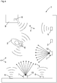
- Figure 1 shows a security system 1 for locating a person 2, with a control and evaluation unit 3, with at least one radio location system 4, with at least one spatially resolving sensor 7 for determining the position of the person 2, the radio location system 4 having radio stations 5 arranged on the person 2
- At least one radio transponder 6 is arranged, whereby position data and classification data of the person 2 can be determined by means of the radio location system 4, the position data and the classification data can be transmitted from the radio station 5 of the radio location system 4 to the control and evaluation unit 3, and by means of the position-resolving sensor 7
- Position data and contour data of the person 2 can be determined, the control and evaluation unit 3 being designed to compare the position data of the radio location system 4 and the position data of the position-resolving sensor 7 and, if they match, to form checked position data, using the control - and evaluation unit 3, the classification data of the radio station 5 are checked for plausibility by comparison with the contour data of the spatially resolving sensor 7.
- Figure 2 shows analogously to Figure 1 a security system for localizing an object 8, with a control and evaluation unit 3, with at least one radio location system 4, with at least one spatially resolving sensor 7 for determining the position of the object 8, the radio location system 4 having radio stations 5 arranged thereon.
- a radio transponder 6 is arranged on the object.
- the security system 1 is formed at least by the control and evaluation unit 3, the radio location system 4 and the position-resolving sensor 7.
- the spatially resolving sensor 7 and the radio location system 4 measure the angle or the direction to the person 2 or the object 8 and the distance to the person 2 or the object 8.
- the control and evaluation unit 3 has inputs, a processing unit and outputs.
- the spatially resolving sensor 7 and the radio stations 5 are connected to the inputs.
- the outputs of the control and evaluation unit 3 can in particular be redundant safety outputs. These are, for example Semiconductor-controlled switching outputs, for example to safely switch off a machine drive.
- the invention uses the combination of two diverse sensor technologies that validate each other with regard to the detection and classification task.
- the first of the two sensor technologies is the radio location system 4 or a radio-based localization system with which the positions of radio transponders 6 can be determined to within a few centimeters.
- the radio location system 4 With the aid of a radio transponder identification and a reference to an object 8 or a person 2 stored thereon, the radio location system 4 also supplies classification information in addition to the position of the object 8 or the person 2.
- the radio location is based, for example, on a triangulation of at least one radio transponder 6 on the person 2 or the object 8. For this purpose, at least three radio stations 5 are necessary that can detect the radio transponder 6.
- the radio location system 4 knows the distance between the respective radio stations 5.
- the radio transponder 6 or the radio transponders 6 are arranged on the person 2 or the object 8.
- the radio stations 5 receive the radio signals from the radio transponders 6 and can thus determine their position and thus the position of the person 2 or the object 8.
- the position data are transmitted from the radio location system 4, namely the radio stations 5, to the control and evaluation unit 3.
- the second system is the spatially resolving sensor 7 or a spatially resolving environment detection system. No radio transponder or tag is required for localization.
- This environment detection system or the spatially resolving sensor 7 thus supplies information that an object 8 is located at a specific position and determines its position and dimensions or contour.
- the two diverse subsystems namely the radio location system 4 and the spatially resolving sensor 7 complement each other very well with regard to the functional tasks of position detection and classification and can therefore be combined alternately for validation and thus for safety-related use.
- a validation of an object or person classification and an object or person position could therefore be carried out schematically in accordance with Figure 1 or Figure 2 proceed as follows:
- the radio location system 4 determines the position of an object 8 or a person 2, the object 8 or the person 2 being identified via the radio transponder 6. This information is transmitted to the control and evaluation unit 3.
- the control and evaluation unit 3 optionally transmits a search field in which the radio location system 4 has identified the person 2 or the object 8 to the position-resolving sensor 7.
- the spatially resolving sensor 7 checks whether a person 2 or an object 8 of suitable size and possibly other validation parameters such as shape, speed, etc. is detected in its detection area or its search field.
- the spatially resolving sensor 7 transmits the recorded data to the control and evaluation unit 3.
- the control and evaluation unit 3 compares the recorded features or the contour of the person 2 or the object 8 of the spatially resolving sensor 7 with the recorded features or the contour of the person 2 or the object 8 of the radio location system 4.
- the recorded position of the person 2 or the object 8 of the radio location system 4 and the recorded position of the person 2 or the object 8 of the spatially resolving sensor 7 are compared with one another.
- both the person or object classification and the person or object position can be mutually validated through the two diverse information channels and thus checked for a safety-related application.
- the radio transponder 6 contains the classification information for the person 2 or the object 8, whereby the person 2 or the object 8 can be clearly identified.
- the spatially resolving sensor 7 and the radio stations 5 are arranged in a stationary manner on a conveyor belt.
- FIG Figure 3 shows a mobile security system 1 for localizing a person 2 or an object 8.
- the spatially resolving sensor 7 and the radio stations 5 are arranged in a mobile manner on a movable machine 11.
- the movable machine 11 or mobile machine can, for example, be a driverless vehicle, driverless vehicle or autonomous vehicle, an automatically guided vehicle (Automated Guided Vehicles, AGV), an automatically mobile robot (Automated Mobile Robots, AMR). , be an industrial mobile robot (IMR) or a robot with movable robot arms.
- the movable machine 11 thus has a drive and can be moved in different directions.
- the spatially resolving sensor 7 is arranged on the front of a vehicle in order to acquire information from the environment.
- a plurality of spatially resolving sensors 7 can also be arranged, in particular at the corners of the vehicle.
- the vehicle can detect its own position based on recognized contours or recognized position of the environment. For example, an orientation takes place on the basis of a known starting point or starting point of the movable machine 11 and is then continuously updated on the basis of detected environmental positions.
- control and evaluation unit 3 is also arranged on the movable machine 11 and connected to the spatially resolving sensor 7.
- the radio location system 4 is an ultra-broadband radio location system, the frequency used being in the range from 3.1 GHz to 10.6 GHz, the transmission energy per radio station being a maximum of 0.5 mW.
- At least only one single radio transponder 6 needs to be arranged on the person 2 or the object 8, which radio transponder 6 is detected by at least three arranged radio stations 5, the distance between the radio stations 5 being known.
- a plurality, for example more than three, radio stations 5 are preferably arranged, which monitor at least part of the movement area of the person 2 or of the object 8.
- At least two or more radio transponders 6 can also be arranged on the person 2 or the object 8.
- the position of person 2 or object 8 can be identified more precisely and the orientation of person 2 or object 8 can also be detected when the vehicle is stationary if the arrangement of radio transponders 6 on person 2 or object 8 is known.
- the spatially resolving sensor 7 is an optoelectronic sensor, in particular a laser scanner 10.
- the spatially resolving sensor 7 is thus designed for at least two-dimensional monitoring of a monitoring area.
- the laser scanner 10 supplies distance values in at least two-dimensional space.
- the sensor outputs measured values with distance information and angle information.
- the distance is determined using the time-of-flight method.
- position detection for example, the laser scanner 10 or the safety laser scanner monitors a measurement data contour.
- control and evaluation unit 3 can be used to change the safety function of the safety system 1.
- the safety function of the safety system 1 is changed. If both subsystems, i.e. the spatially resolving sensor 7 and the radio location system 4, provide a coherent and mutually assignable position, then a predetermined position, which is stored, for example, can be recognized and the control and evaluation unit 3 can switch to another protective measure or safety function.
- Switching the protective measure can include, for example, switching measurement data contours, switching protective fields, adapting the size or shape of measurement data contours or protective fields and / or switching the properties of a protective field.
- the properties of a protective field include, for example, the resolution and / or the response time of the protective field.
- a switchover of the protective measure can also be a safety function, such as a force limitation of the drive, to which a switchover is made.
- position data checked by means of the control and evaluation unit 3 are checked for correspondence with stored position data of a safety point, and if they match, the safety function of the safety system 1 is changed.
- the radio stations 5 and the spatially resolving sensor 7 are arranged in a stationary manner.
- a radio transponder 6 is arranged on the person 2.
- Another radio transponder 6 is arranged on an object 8.
- FIG Figure 5 shows a stationary security system 1 for localizing a person 2 or an object 8.
- the radio stations 5 and the spatially resolving sensor 7 are arranged in a stationary manner.
- Two radio transponders 6 are arranged on a mobile vehicle.
Landscapes
- Engineering & Computer Science (AREA)
- Radar, Positioning & Navigation (AREA)
- Remote Sensing (AREA)
- Computer Networks & Wireless Communication (AREA)
- Physics & Mathematics (AREA)
- General Physics & Mathematics (AREA)
- Signal Processing (AREA)
- Electromagnetism (AREA)
- Business, Economics & Management (AREA)
- Health & Medical Sciences (AREA)
- Emergency Management (AREA)
- Environmental & Geological Engineering (AREA)
- Public Health (AREA)
- Radar Systems Or Details Thereof (AREA)
- Position Fixing By Use Of Radio Waves (AREA)
Abstract
Description
- Die vorliegende Erfindung betrifft ein Sicherheitssystem zur Lokalisierung einer Person oder eines Objektes gemäß dem Oberbegriff von Anspruch 1 und ein Verfahren zur Lokalisierung einer Person oder eines Objektes gemäß dem Oberbegriff von Anspruch 11.
- Die Sensorik der funktionalen Sicherheit ist aktuell auf dem Stand, dass grundlegende physikalische Merkmale der Umgebung, beispielsweise Geometrieinformationen wie z. B. Abstände, Längen oder die Anwesenheit von Objekten an sich zuverlässig erfasst und in einfachen Sicherheitsfunktionen verwendet werden können. Dagegen sind höherwertige Informationen oder abgeleitete Bedeutungen, zum Beispiel die Information, um was für ein Objekt es sich handelt, in aller Regel nicht zuverlässig durch Sensoren ermittelbar und daher auch nicht sicherheitstechnisch nutzbar.
- In diesem Sinne ist insbesondere die Information, ob es sich bei einem Objekt, um eine Person handelt oder nicht, für hochwertige Sicherheitsfunktionen interessant. Diese sichere Objektklassifikation konnte bisher noch nicht realisiert werden, ist aber im Hinblick auf die situationsbezogene Steuerung der Maschine sehr wichtig. Im Allgemeinen ist bereits eine Objektklassifikation ein sehr aufwändiges Verfahren, da hierfür in der Regel Bilddaten verwendet werden, die dann sehr aufwändig prozessiert werden müssen. Dies führt in der Regel zu teuren Sensoren mit oftmals erheblichen Latenzzeiten.
- Optoelektronische Sicherheitssensoren, beispielsweise Laserscanner oder Lichtgitter erfassen sehr zuverlässig die Anwesenheit eines Objektes oder einer Person. Derartige Sicherheitssensoren finden eine große Verbreitung bei der Gefahrstellenabsicherung von Maschinen und ermöglichen die Implementierung sehr einfacher Sicherheitsfunktionen.
- Maschinenbewegungen werden bei Detektion eines sicherheitsrelevanten Objekts in aller Regel gestoppt oder verlangsamt. Dabei bleibt unberücksichtigt, um was für ein Objekt es sich handelt. Diese Information ist im Allgemeinen auch gar nicht verfügbar bzw. nicht sicherheitstechnisch verwendbar.
- Eine einfache Detektionsfunktion vorhandener Sicherheitssensoren erlaubt eine zuverlässige Absicherung von Gefahrstellen hat aber in alle Regel nachteilige Auswirkungen auf eine Produktivität einer Maschine. Unabhängig von einer Klasse des detektierten Objekts beispielsweise einer Person, einem Gegenstand oder einer Störung bzw. störenden Gegenständen muss sicherheitsgerichtet abgeschaltet werden, selbst wenn diese Reaktion in bestimmten Fällen nicht erforderlich wäre.
- Insbesondere ein sicheres Wissen, dass es sich bei einem detektierten Objekt um eine Person handelt oder nicht, würde eine sehr viel spezifischere Kontrolle einer potenziell gefährlichen Maschine ermöglichen.
- Ein autonomes Fahrzeug zum Beispiel wird sehr vorsichtig agieren müssen, wenn es die Anwesenheit einer Person im Fahrweg erfasst, da in diesem Fall keine Information über das zukünftige Verhalten der Person vorliegen. Handelt es sich bei dem Objekt jedoch um ein anderes Fahrzeug, dann besteht keine Gefahr der Gefährdung einer Person und das Fahrzeug muss kein unvorhergesehenes Verhalten einplanen. Betriebsparameter können in diesem Fall im Hinblick auf die Produktivität optimiert werden.
- Die
DE 10 2016 217 531 A1 offenbart beispielsweise ein Verfahren zur Verbesserung der Verkehrssicherheit, insbesondere von verletzlichen Straßenverkehrsteilnehmern. Dabei wird zumindest eine Funkmessung mittels Ultra-Wideband-Funktechnologie (UWB) zwischen zumindest einer Funkstation eines Fahrzeugs und einer mobilen Funkstelle eines Verkehrsteilnehmers durchgeführt. - Eine Aufgabe der Erfindung besteht darin, eine sichere Unterscheidung von Mensch und Gegenstand zu ermöglichen. Damit sollen hochwertige Sicherheitsfunktionen wie zum Beispiel die gezielte Interaktion zwischen Mensch und Roboter oder zwischen Mensch und mobilen Robotern realisiert werden können.
- Die Aufgabe wird gemäß Anspruch 1 gelöst durch ein Sicherheitssystem zur Lokalisierung einer Person oder eines Objektes, mit einer Steuer- und Auswerteeinheit, mit mindestens einem Funkortungssystem, mit mindestens einem ortsauflösenden Sensor zur Positionsbestimmung der Person oder des Objektes, wobei das Funkortungssystem angeordnete Funkstationen aufweist, wobei an der Person oder dem Objekt mindestens ein Funktransponder angeordnet ist, wobei mittels dem Funkortungssystem Positionsdaten und Klassifizierungsdaten der Person oder des Objektes ermittelbar sind, wobei die Positionsdaten und die Klassifizierungsdaten von der Funkstation des Funkortungssystems an die Steuer- und Auswerteeinheit übermittelbar sind, und mittels dem ortsauflösenden Sensor Positionsdaten und Konturdaten der Person oder des Objekts ermittelbar sind, wobei die Steuer- und Auswerteeinheit ausgebildet ist, die Positionsdaten des Funkortungssystems und die Positionsdaten des Sensors zu vergleichen und bei einer Übereinstimmung geprüfte Positionsdaten zu bilden, wobei die Steuer- und Auswerteeinheit ausgebildet ist die Klassifizierungsdaten der Funkstation mit den Konturdaten des ortsauflösenden Sensors zu vergleichen und auf Plausibilität zu prüfen.
- Die Aufgabe wird weiter gemäß Anspruch 11 gelöst durch ein Verfahren zur Lokalisierung einer Person oder eines Objektes, mit einer Steuer- und Auswerteeinheit, mit mindestens einem Funkortungssystem, mit mindestens einem ortsauflösenden Sensor zur Positionsbestimmung der Person oder des Objektes, wobei das Funkortungssystem angeordnete Funkstationen aufweist, wobei an der Person oder dem Objekt mindestens ein Funktransponder angeordnet ist, wobei mittels dem Funkortungssystem Positionsdaten und Klassifizierungsdaten der Person oder des Objektes ermittelt werden, wobei die Positionsdaten und die Klassifizierungsdaten von der Funkstation des Funkortungssystems an die Steuer- und Auswerteeinheit übermittelt werden, und mittels dem ortsauflösenden Sensor Positionsdaten und Konturdaten der Person oder des Objekts ermittelt werden, wobei die Steuer- und Auswerteeinheit die Positionsdaten des Funkortungssystems und die Positionsdaten des Sensors vergleicht und bei einer Übereinstimmung geprüfte Positionsdaten bildet, wobei die Steuer- und Auswerteeinheit die Klassifizierungsdaten der Funkstation mit den Konturdaten des ortsauflösenden Sensors vergleicht und auf Plausibilität überprüft.
- Das Funkortungssystem ermöglicht auf günstige und einfache Art die Klassifizierung von Personen oder Objekten. Gemäß der Erfindung kann eine Auswertung in höheren semantischen Ebenen erfolgen. So ist es zum Beispiel möglich verschiedene Verhaltensmuster vorherzusagen und zu validieren. Dies kann anhand von einfachen Regelwerken passieren. Oberhalb der Verhaltensebenen ist dann gar eine bewusste Steuerung, nämlich eine Vergabe von Arbeitsaufgaben möglich.
- Das Sicherheitssystem wird mindestens durch die Steuer- und Auswerteeinheit, das Funkortungssystem und den ortsauflösenden Sensor gebildet.
- Der ortsauflösende Sensor und das Funkortungssystem messen den Winkel bzw. die Richtung zu der Person oder dem Objekt und die Entfernung zu der Person oder dem Objekt. Damit kann der ortsauflösende Sensor auch als Ortungssensor bezeichnet werden.
- Die Steuer- und Auswerteeinheit weist Eingänge, eine Verarbeitungseinheit und Ausgänge auf. An die Eingänge ist der ortsauflösende Sensor und die Funkstationen angeschlossen. Die Steuer- und Auswerteeinheit kann eine modulare Steuer- und Auswerteeinheit sein die über eine Software programmierbar ist.
- Bei den Ausgängen der Steuer- und Auswerteeinheit kann es sich insbesondere um redundante Sicherheitsausgänge handeln. Dabei handelt es sich beispielsweise um halbleitergesteuerte Schaltausgänge, um beispielsweise einen Antrieb einer Maschine sicher abzuschalten.
- Die Erfindung beruht darauf, dass eine Position der Person oder des Objekts durch zwei voneinander unabhängige Merkmale eindeutig identifizierbar ist. Diese Merkmale sind die Position die über den ortsauflösenden Sensor ermittelt wird, sowie die Position, welche über das Funkortungssystem ermittelt wird. Damit wird die Position durch ein redundantes, insbesondere diversitäres System bestimmt.
- Die Erfindung nutzt die Kombination von zwei diversitären Sensortechnologien aus, die sich im Hinblick auf die Detektions- und Klassifizierungsaufgabe gegenseitig validieren.
- Die erste der beiden Sensortechnologien ist das Funkortungssystem bzw. ein funkbasiertes Lokalisierungssystem mit dem die Positionen von Funktranspondern bis auf wenige Zentimeter genau bestimmt werden kann. Mit Hilfe einer Funktransponder Identifikation und einem darauf hinterlegten Bezug zu einem Objekt oder eine Person liefert das Funkortungssystem zusätzlich zur Position des Objektes oder der Person auch eine Klassifizierungsinformation.
- Dieses System muss nicht im Sinne der funktionalen Sicherheit entwickelt und zertifiziert sein, sondern kann im Rahmen von ohnehin genutzten Automatisierungs- oder Logistikfunktionen für eine Sicherheitsanwendung mitgenutzt werden.
- Die Funkortung basiert dabei beispielsweise auf einer Triangulation von mindestens einem Funktransponder an der Person oder dem Objekt. Hierzu sind mindestens drei Funkstationen notwendig die den Funktransponder erfassen können. Dabei ist dem Funkortungssystem der Abstand zwischen den jeweiligen Funkstationen bekannt.
- Es handelt es sich vorzugsweise um ein Echtzeitortungssystem oder der englischen Entsprechung RTLS (Real-Time-Locating-System). Dabei ist der Funktransponder oder sind die Funktransponder an der Person oder dem Objekt angeordnet. Die Funkstationen erhalten die Funksignale von den Funktranspondern und können so deren Position und damit die Position der Person oder des Objekts bestimmen.
- Dabei werden die Positionsdaten von dem Funkortungssystem, nämlich den Funkstationen an die Steuer- und Auswerteeinheit übermittelt.
- Bei dem Funkortungssystem kann es sich auch um Funkfrequenzen von Funknetzwerken wie WLAN oder Wi-Fi handeln. Beispielsweise wird ein 2,4 GHz oder ein 5 GHz Band bei einer Bandbreite von 20 MHz oder 40 MHz verwendet.
- Bei dem Funkortungssystem kann es sich auch um Funkfrequenzen von Funkverbindungen wie Bluetooth handeln. Dabei werden Funkfrequenzen von 2,402 und 2,480 GHz verwendet. Der Vorteil dieser Frequenzen ist, dass diese weltweit zulassungsfrei betrieben werden dürfen. Je nach verwendeter Leistung können dabei Reichweiten von 0 bis 100 m erreicht werden. Die Reichweiten und die zugehörigen maximalen Leistungen sind in Klassen 1 bis 3 eingeteilt
- Das zweite System ist der ortsauflösende Sensor bzw. ein ortsauflösendes Umfelderfassungssystem. Hierbei wird kein Tag zur Lokalisierung benötigt. Damit sind für den ortsauflösenden Sensor keine direkten Klassifizierungsinformationen zugänglich. Dieses Umfelderfassungssystem bzw. der ortsauflösende Sensor liefert also Informationen, dass sich ein Objekt an einer bestimmten Position befindet und ermittelt dessen Position und Abmessung bzw. Kontur.
- Die beiden diversitären Teilsysteme, nämlich das Funkortungssystem und der ortsauflösende Sensor ergänzen sich sehr gut im Hinblick auf die funktionalen Aufgaben Positionserfassung und Klassifikation und können daher wechselseitig zur Validierung und damit zur sicherheitstechnischen Verwendung kombiniert werden.
- Eine Validierung einer Objekt- oder Personenklassifikation und einer Objekt- oder Personenposition könnte also schematisch wie folgt ablaufen:
Das Funkortungssystem ermittelt die Position eines Objektes oder einer Person, wobei das Objekt über den Funktransponder identifiziert wird. Diese Informationen werden der Steuer- und Auswerteeinheit übermittelt. - Optional übermittelt die Steuer- und Auswerteeinheit ein Suchfeld in dem das Funkortungssystem die Person oder das Objekt identifiziert hat an den ortsauflösenden Sensor.
- Der ortsauflösende Sensor prüft, ob in seinem Erfassungsbereich oder seinem Suchfeld eine Person oder ein Objekt passender Größe und ggf. anderer Validierungsparameter wie Form, Geschwindigkeit usw. detektiert. Der ortsauflösende Sensor übermittelt die erfassten Daten an die Steuer- und Auswerteeinheit.
- Die Steuer- und Auswerteeinheit vergleicht die erfassten Merkmale bzw. die Kontur der Person oder des Objektes des ortsauflösenden Sensors mit den erfassten Merkmalen bzw. der Kontur der Person oder des Objektes des Funkortungssystems.
- Zusätzlich wird die erfasste Position der Person oder des Objektes des Funkortungssystems und die erfasste Position der Person oder des Objektes des ortsauflösenden Sensors miteinander verglichen.
- Somit kann sowohl die Personen- bzw. Objektklassifikation, als auch die Personen- bzw. Objektposition wechselseitig durch die beiden diversitären Informationskanäle validiert und so für eine sicherheitstechnische Anwendung geprüft werden.
- Gemäß der Erfindung enthält der Funktransponder die Klassifizierungsinformation für die Person oder das Objekt, wodurch die Person oder das Objekt eindeutig identifizierbar ist.
- Die Erfindung ermöglicht eine sichere Klassifikation von Personen oder Objekten in einem Überwachungsbereich und erschließt damit die Möglichkeit eine Sicherheitsfunktion spezifisch auf eine jeweilige Situation zuzuschneiden. Damit besteht die Möglichkeit eine Forderung nach einer Risikominderung zu erfüllen, ohne eine Produktivität eines Automatisierungsprozesses zu beeinträchtigen.
- Es kann häufig eine bestehende Infrastruktur genutzt werden. Im industriellen Umfeld, aber auch im öffentlichen Bereich, z. B. in Krankenhäusern werden Funkortungssysteme eingesetzt, beispielsweise um fahrerlose Transportfahrzeuge zu orten.
- Eine Klassifizierung von Personen oder Objekten erfordert gemäß der Erfindung wenig Rechenaufwand. Die Sensorik ist preiswert und häufig kann sogar bestehende Infrastruktur verwendet werden. Zudem verursacht die Klassifizierung keine nachteilige Latenzzeiten, was ein sehr großer Vorteil für die industrielle Sicherheitstechnik ist. Auch für die Mensch-Roboter-Kollaboration, in der Personen in unmittelbarer Nähe zur Gefahrstelle agieren müssen ist die Erfindung vorteilhaft einsetzbar.
- Die physikalischen Wirkprinzipien und deren Stärken und Schwächen der diversitären Sensoren sind vorteilhaft komplementär. Funkortungssysteme weisen beispielsweise aufgrund des Wirkprinzips eine natürliche Immunität gegenüber Fremdlicht auf. Weiter sind Funkortungssysteme wenig empfindlich bei störenden Objekten wie Staub, Spänen oder Nebel. Zudem ist es durch Funkortungssysteme möglich durch nichtmetallische Wände hindurchzusehen, so dass eine besonders frühe Erkennung von Personen oder Objekten möglich ist. Diese erlaubt eine qualitativ hochwertige Optimierung von Prozessen bei steter Gewährleistung der Arbeitssicherheit.
- Bei dem Objekt kann es sich um stationäre oder mobile Gegenstände handeln. Beispielsweise handelt es sich bei dem Objekt um Transportmaterial oder Verarbeitungsmaterial.
- In Weiterbildung der Erfindung sind der ortsauflösende Sensor und die Funkstationen stationär angeordnet oder mobil an einer bewegbaren Maschine angeordnet.
- Bei der bewegbaren Maschine bzw. mobilen Maschine kann es sich beispielsweise um ein führerloses Fahrzeug, fahrerloses Fahrzeug bzw. autonomes Fahrzeug, um ein automatisch geführtes Fahrzeug (Automated Guided Vehicles, AGV), um ein automatisch mobilen Roboter (Automated Mobile Robots, AMR), um ein industriemobilen Roboter (Industrial Mobile Robots, IMR) oder um einen Roboter mit bewegbaren Roboterarmen handeln. Die bewegbare Maschine weist somit einen Antrieb auf und kann in verschiedenen Richtungen bewegt werden.
- Beispielsweise ist der ortsauflösende Sensor an der Frontseite eines Fahrzeuges angeordnet, um Informationen aus der Umgebung zu erfassen. Es können auch mehrere ortsauflösende Sensoren, insbesondere an den Ecken des Fahrzeuges angeordnet sein.
- Dadurch kann das Fahrzeug seine eigene Position aufgrund von erkannten Konturen oder erkannten Position der Umgebung erfassen. Beispielsweise erfolgt einer Orientierung ausgehend von einem bekannten Ausgangspunkt oder Startpunkt der bewegbaren Maschine und wird dann fortlaufend anhand von detektierten Umgebungspositionen aktualisiert.
- Die Steuer- und Auswerteeinheit ist in diesem Fall ebenfalls an der bewegbaren Maschine angeordnet und mit dem ortsauflösenden Sensor verbunden.
- Die Ausgänge der Steuer- und Auswerteeinheit sind mit Funktionseinheiten wie dem Antrieb, den Bremsen und/oder der Lenkung der bewegbaren Maschine verbunden.
- Bei der stationären Anordnung kann es sich um eine Anordnung an einer Maschine, einer Förderstrecke, einem Durchgang oder ähnliches handeln.
- In Weiterbildung der Erfindung ist das Funkortungssystem ein Ultrabreitband-Funkortungssystem, wobei die verwendete Frequenz im Bereich von 3,1 GHz bis 10,6 GHz ist, wobei die Sendeenergie pro Funkstation maximal 0,5 mW beträgt.
- Eine absolute Bandbreite beträgt bei einem Ultrabreitband-Funkortungssystem wenigstens 500 MHz oder eine relative Bandbreite beträgt mindestens 20% der zentralen Frequenz.
- Die Reichweite eines derartigen Funkortungssystems beträgt beispielsweise 0 bis 50 m. Dabei wird die kurze zeitliche Dauer der Funkpulse für die Ortung benutzt.
- Das Funkortungssystem sendet damit nur Funkwellen mit einer niedrigen Energie aus. Das System ist sehr flexibel einsetzbar und weist keine Interferenzen auf.
- An der Person oder dem Objekt muss minimal nur ein einziger Funktransponder angeordnet sein, der von mindestens drei stationär angeordneten Funkstationen erfasst wird, wobei der Abstand der Funkstationen bekannt ist.
- Vorzugsweise sind eine Vielzahl, beispielsweise mehr als drei Funkstationen angeordnet, welche mindestens einen Teil des Bewegungsbereichs der Person oder des Objektes überwachen.
- Es können auch mindestens zwei oder mehr Funktransponder an der Person oder dem Objekt angeordnet sein. Dadurch kann die Position der Person oder des Objektes genauer identifiziert werden und auch die Ausrichtung der Person oder des Objektes im Stillstand erfasst werden, wenn die Anordnung der Funktransponder an der Person oder dem Objekt bekannt ist.
- In Weiterbildung der Erfindung ist der ortsauflösende Sensor ein optoelektronischer Sensor, ein Ultraschallsensor oder ein Radarsensor.
- Bei einem Lichtlaufzeitsensor wird das von einem Lichtsender ausgesendete Licht welches von der Person oder dem Objekt remittiert wird von einem Lichtempfänger empfangen und die Lichtlaufzeit vom Aussenden bis zum Empfangen von der Person oder dem Objekt wird ausgewertet, wodurch die Entfernung zu der Person oder dem Objekt bestimmt werden kann.
- Jedoch kann der Sensor auch ein Ultraschallsensor, oder ein Radar-Sensor sein.
- Ein Ultraschallsensor sendet Ultraschall aus und wertet die reflektierten Schallwellen, also die Echosignale aus. Dabei werden Frequenzen ab 16 kHz verwendet. Dabei können Detektionsreichweiten von wenigen Zentimetern bis vielen Metern realisiert werden.
- Ein Radarsensor ist ein Sensor, der ein sogenanntes Primärsignal als gebündelte elektromagnetische Welle aussendet, die von Personen oder Objekten reflektierten Echos als Sekundärsignal empfängt und nach verschiedenen Kriterien auswertet. Dabei handelt es sich um eine Ortung, nämlich der Bestimmung von Entfernung und Winkel.
- Aus den empfangenen, von der Person oder dem Objekt reflektierten Wellen können Positionsinformationen bzw. die Position gewonnen werden. Wie bereits erwähnt kann der Winkel bzw. die Richtung zum Objekt und die Entfernung zur Person oder dem Objekt aus der Zeitverschiebung zwischen Senden und Empfangen des Signals ermittelt werden. Weiter kann auch die Relativbewegung zwischen Sender und Person bzw. Objekt festgestellt werden, beispielsweise durch eine einfache Mehrfachmessung in zeitlichen Abständen. Das Aneinanderreihen einzelner Messungen liefert die Wegstrecke und die Absolutgeschwindigkeit des Objektes. Bei entsprechender Auflösung des Radarsensors können Konturen der Person bzw. des Objektes erkannt werden.
- Eine Abstrahlung von dem Radarsensor erfolgt beispielsweise aufgrund des Antennenentwurfs weitgehend gebündelt in eine Richtung. Die Strahlungscharakteristik der Antenne hat dann eine sogenannte Keulenform.
- Die Wellenlänge des Radars liegt im Bereich der Funkwellen im Kurz- bis Mikrowellenbereich. Ein Pulsradarsensor sendet Impulse mit einer typischen Dauer im unteren Mikrosekundenbereich und wartet dann auf Echos. Die Laufzeit des Impulses ist die Zeit zwischen dem Senden und dem Empfang des Echos. Sie wird zur Entfernungsbestimmung genutzt.
- Eine Richtung des Abtaststrahles eines Impulsradarsensors kann statt durch die Ausrichtung der Antenne bzw. der Antennen auch elektronisch durch phasengesteuerte Antennenarrays bewirkt werden. Damit können in schnellem Wechsel mehrere Objekte angepeilt und quasi simultan verfolgt werden.
- Der Radarsensor arbeitet mit einer Leistung von beispielsweise ca. 10 mW. Diese Leistung ist so gering, dass keine gesundheitlichen Auswirkungen bestehen. Die für diese Anwendung zugelassene Radarfrequenz liegt beispielsweise im Bereich von 76-77 GHz, entsprechend einer Wellenlänge von etwa 4 mm.
- In Weiterbildung der Erfindung ist der ortsauflösende Sensor zur mindestens flächigen Überwachung eines Überwachungsbereiches ausgebildet.
- Der ortsauflösende Sensor zur mindestens flächigen Überwachung eines Überwachungsbereiches ist ein Sensor zur Entfernungsmessung. Der Entfernungssensor liefert Entfernungswerte im mindestens zweidimensionalen Raum. Dabei gibt der Sensor Messwerte mit Distanzangaben und Winkelangaben aus. Beispielsweise wird die Entfernung mittels Lichtlaufzeitverfahren oder Triangulationsverfahren ermittelt.
- In Weiterbildung der Erfindung ist der ortsauflösende Sensor zur mindestens räumlichen Überwachung eines Überwachungsbereiches ausgebildet.
- In Weiterbildung der Erfindung ist der ortsauflösende oder optoelektronische Sensor ein Laserscanner, ein Sicherheitslaserscanner, eine 3D-Kamera, eine Stereokamera oder eine Lichtlaufzeitkamera.
- Zur Positionserfassung überwacht der Laserscanner, der Sicherheitslaserscanner, die 3D-Kamera, die Stereokamera oder die Lichtlaufzeitkamera eine zweidimensionale oder dreidimensionale Messdatenkontur der Person oder des Objektes aus. Dabei kann es sich auch synonym um ein Überwachungsfeld handeln.
- Zur Positionserfassung überwacht beispielsweise der Laserscanner, bzw. der Sicherheitslaserscanner eine Messdatenkontur.
- In der Sicherheitstechnik eingesetzte Sicherheitssysteme müssen besonders zuverlässig und eigensicher arbeiten und deshalb hohe Sicherheitsanforderungen erfüllen, beispielsweise die Norm EN 13849 für Maschinensicherheit und die Gerätenorm EN61496 für berührungslos wirkende Schutzeinrichtungen (BWS).
- Zur Erfüllung dieser Sicherheitsnormen sind eine Reihe von Maßnahmen zu treffen, wie beispielsweise sichere elektronische Auswertung durch redundante und/oder diversitäre Elektronik oder verschiedene Funktionsüberwachungen, speziell die Überwachung der Verschmutzung optischer Bauteile einschließlich einer Frontscheibe. Ein Sicherheitslaserscanner entsprechend derartigen Normen ist beispielsweise aus der
DE 43 40 756 A1 bekannt. - Der Begriff ,funktional sicher ist im Sinne der genannten oder vergleichbaren Normen zu verstehen, es sind also Maßnahmen ergriffen, um Fehler bis zu einem spezifizierten Sicherheitsniveau zu beherrschen. Das Sicherheitssystem kann daher eigensicher ausgebildet sein. Das Sicherheitssystem und/oder mindestens ein nicht sicherer Sensor erzeugen zudem nicht sichere Daten, wie Rohdaten, Punktwolken oder dergleichen. Nicht sicher ist der Gegenbegriff zu sicher, für nicht sichere Geräte, Übertragungswege, Auswertungen und dergleichen und dabei sind demnach die genannten Anforderungen an eine Fehlersicherheit nicht erfüllt.
- Eine 3D-Kamera überwacht beispielsweise ebenfalls einen Überwachungsbereich mittels einer Vielzahl von erfassten Distanzwerten. Eine 3D-Kamera hat den Vorteil, dass ein volumenartiger Schutzbereich überwacht werden kann.
- Eine Stereokamera überwacht beispielsweise ebenfalls einen Überwachungsbereich mittels einer Vielzahl von erfassten Distanzwerten. Die Distanzwerte werden auf Basis der zwei Kameras der Stereokamera ermittelt, die in einem Basisabstand zueinander montiert sind. Eine Stereokamera hat ebenso den Vorteil, dass ein volumenartiger Schutzbereich überwacht werden kann.
- Mittels einer Lichtlaufzeitkamera werden Distanzwerte aufgrund der gemessenen Lichtlaufzeit ermittelt, welche von einem Bildsensor ermittelt werden. Eine Lichtlaufzeitkamera hat ebenso den Vorteil, dass ein volumenartiger bzw. räumlicher Schutzbereich überwacht werden kann.
- In Weiterbildung der Erfindung erfolgt aufgrund der geprüften Positionsdaten mittels der Steuer- und Auswerteeinheit eine Veränderung der Sicherheitsfunktion des Sicherheitssystems.
- Basierend auf übereinstimmenden Positionsdaten mittels der Steuer- und Auswerteeinheit erfolgt eine Veränderung der Sicherheitsfunktion des Sicherheitssystems.
- Wenn beide Teilsysteme, also der ortsauflösende Sensor und das Funkortungssystem eine stimmige und aufeinander zuordenbare Position liefern, dann kann eine vorbestimmte Position, welche beispielsweise abgespeichert ist erkannt sein und die Steuer- und Auswerteeinheit kann auf eine andere Schutzmaßnahme bzw. Sicherheitsfunktion umschalten. Das Umschalten der Schutzmaßnahme kann beispielsweise ein Umschalten von Messdatenkonturen, ein Umschalten von Schutzfeldern, eine Größen- oder Formanpassung von Messdatenkonturen oder Schutzfeldern und/oder eine Umschaltung der Eigenschaften eines Schutzfeldes umfassen. Zu den Eigenschaften eines Schutzfeldes gehören beispielsweise die Auflösung und/oder die Reaktionszeit des Schutzfeldes. Ein Umschalten der Schutzmaßnahme kann auch eine Sicherheitsfunktion, wie beispielsweise eine Kraftbegrenzung des Antriebs sein, auf die umgeschaltet wird.
- In Weiterbildung der Erfindung werden mittels der Steuer- und Auswerteeinheit geprüften Positionsdaten mit gespeicherten Positionsdaten eines Sicherheitspunktes auf Übereinstimmung geprüft und bei einer Übereinstimmung erfolgt eine Veränderung der Sicherheitsfunktion des Sicherheitssystems.
- Der Sicherheitspunkt (Safe Point of Interest, SPol) ist eine vereinfachte Variante einer sicheren Positionierung, die sich auf eine Detektion besonderer Positionen in einer industriellen Anwendung beschränkt, an denen es erforderlich ist das Sicherheitssystem bzw. eine Schutzeinrichtung oder eine Sicherheitsfunktion der bewegbaren Maschine anzupassen, um sowohl einen Personenschutz wie auch eine Maschinenverfügbarkeit zu gewährleisten. Bei dem Sicherheitspunkt handelt es sich als synonyme Bezeichnung um einen Sicherheitsort, also keinen singularen Punkt.
- In Weiterbildung der Erfindung weist das Sicherheitssystem eine Karte oder ein Kartenmodel auf, wobei der mindestens eine Sicherheitspunkt in der Karte oder dem Kartenmodel eingetragen ist und eine Navigation der bewegbaren Maschine in der Karte oder dem Kartenmodel erfolgt.
- Die aktuelle Position und/oder Lage der bewegbaren Maschine wird in der Steuer- und Auswerteeinheit aufgrund erfasster Umgebungskonturen kontinuierlich verarbeitet und die Karte oder das Kartenmodell aktualisiert. Die Karte weist ein Koordinatensystem auf. Diese Art der Positionsbestimmung wird als Simultaneous-Localisation-and-Mapping (kurz: SLAM) Methode bezeichnet. Dabei ist mindestens eine Position und eine zugehörige Orientierung in der Karte bekannt, bzw. eine Ursprungsposition und Ursprungsorientierung in der Karte bekannt. Erkannte Positionen und/oder Konturen werden in die Karte fortlaufend eingetragen, wodurch die Karte erweitert wird bzw. Veränderungen von beispielsweise Objekten und/oder Fahrwegen in die Karte eingetragen werden.
- Die Erfindung wird nachstehend auch hinsichtlich weiterer Vorteile und Merkmale unter Bezugnahme auf die beigefügte Zeichnung anhand von Ausführungsbeispielen erläutert. Die Figuren der Zeichnung zeigen in:
- Figur 1
- ein Sicherheitssystem zur Lokalisierung einer Person;
- Figur 2
- ein Sicherheitssystem zur Lokalisierung eines Objekts;
- Figur 3
- ein mobiles Sicherheitssystem zur Lokalisierung einer Person oder eines Objekts;
- Figur 4
- ein stationäres Sicherheitssystem zur Lokalisierung einer Person oder eines Objektes;
- Figur 5
- ein stationäres Sicherheitssystem zur Lokalisierung einer Person oder eines Objekts.
- In den nachfolgenden Figuren sind identische Teile mit identischen Bezugszeichen versehen.
-
Figur 1 zeigt ein Sicherheitssystem 1 zur Lokalisierung einer Person 2, mit einer Steuer- und Auswerteeinheit 3, mit mindestens einem Funkortungssystem 4, mit mindestens einem ortsauflösenden Sensor 7 zur Positionsbestimmung der Person 2, wobei das Funkortungssystem 4 angeordnete Funkstationen 5 aufweist, wobei an der Person 2 mindestens ein Funktransponder 6 angeordnet ist, wobei mittels dem Funkortungssystem 4 Positionsdaten und Klassifizierungsdaten der Person 2 ermittelbar sind, wobei die Positionsdaten und die Klassifizierungsdaten von der Funkstation 5 des Funkortungssystems 4 an die Steuer- und Auswerteeinheit 3 übermittelbar sind, und mittels dem ortsauflösenden Sensor 7 Positionsdaten und Konturdaten der Person 2 ermittelbar sind, wobei die Steuer- und Auswerteeinheit 3 ausgebildet ist, die Positionsdaten des Funkortungssystems 4 und die Positionsdaten des ortsauflösenden Sensors 7 zu vergleichen und bei einer Übereinstimmung geprüfte Positionsdaten zu bilden, wobei mittels der Steuer- und Auswerteeinheit 3 die Klassifizierungsdaten der Funkstation 5 durch Vergleich mit den Konturdaten des ortsauflösenden Sensors 7auf Plausibilität geprüft werden. -
Figur 2 zeigt analog zuFigur 1 ein Sicherheitssystem zur Lokalisierung eines Objektes 8, mit einer Steuer- und Auswerteeinheit 3, mit mindestens einem Funkortungssystem 4, mit mindestens einem ortsauflösenden Sensor 7 zur Positionsbestimmung des Objektes 8, wobei das Funkortungssystem 4 angeordnete Funkstationen 5 aufweist. An dem Objekt ist eine Funktransponder 6 angeordnet. - Das Sicherheitssystem 1 wird mindestens durch die Steuer- und Auswerteeinheit 3, das Funkortungssystem 4 und den ortsauflösenden Sensor 7 gebildet.
- Der ortsauflösende Sensor 7 und das Funkortungssystem 4 messen den Winkel bzw. die Richtung zu der Person 2 oder dem Objekt 8 und die Entfernung zu der Person 2 oder dem Objekt 8.
- Die Steuer- und Auswerteeinheit 3 weist Eingänge, eine Verarbeitungseinheit und Ausgänge auf. An die Eingänge ist der ortsauflösende Sensor 7 und die Funkstationen 5 angeschlossen.
- Bei den Ausgängen der Steuer- und Auswerteeinheit 3 kann es sich insbesondere um redundante Sicherheitsausgänge handeln. Dabei handelt es sich beispielsweise um halbleitergesteuerte Schaltausgänge, um beispielsweise einen Antrieb einer Maschine sicher abzuschalten.
- Die Erfindung nutzt die Kombination von zwei diversitären Sensortechnologien aus, die sich im Hinblick auf die Detektions- und Klassifizierungsaufgabe gegenseitig validieren.
- Die erste der beiden Sensortechnologien ist das Funkortungssystem 4 bzw. ein funkbasiertes Lokalisierungssystem mit dem die Positionen von Funktranspondern 6 bis auf wenige Zentimeter genau bestimmt werden kann. Mit Hilfe einer Funktransponder Identifikation und einem darauf hinterlegten Bezug zu einem Objekt 8 oder eine Person 2 liefert das Funkortungssystem 4 zusätzlich zur Position des Objektes 8 oder der Person 2 auch eine Klassifizierungsinformation.
- Die Funkortung basiert dabei beispielsweise auf einer Triangulation von mindestens einem Funktransponder 6 an der Person 2 oder dem Objekt 8. Hierzu sind mindestens drei Funkstationen 5 notwendig die den Funktransponder 6 erfassen können. Dabei ist dem Funkortungssystem 4 der Abstand zwischen den jeweiligen Funkstationen 5 bekannt.
- Es handelt es sich vorzugsweise um ein Echtzeitortungssystem oder der englischen Entsprechung RTLS (Real-Time-Locating-System). Dabei ist der Funktransponder 6 oder sind die Funktransponder 6 an der Person 2 oder dem Objekt 8 angeordnet. Die Funkstationen 5 erhalten die Funksignale von den Funktranspondern 6 und können so deren Position und damit die Position der Person 2 oder des Objekts 8 bestimmen.
- Dabei werden die Positionsdaten von dem Funkortungssystem 4, nämlich den Funkstationen 5 an die Steuer- und Auswerteeinheit 3 übermittelt.
- Das zweite System ist der ortsauflösende Sensor 7 bzw. ein ortsauflösendes Umfelderfassungssystem. Hierbei wird kein Funktransponder bzw. Tag zur Lokalisierung benötigt. Dieses Umfelderfassungssystem bzw. der ortsauflösende Sensor 7 liefert also Informationen, dass sich ein Objekt 8 an einer bestimmten Position befindet und ermittelt dessen Position und Abmessung bzw. Kontur.
- Die beiden diversitären Teilsysteme, nämlich das Funkortungssystem 4 und der ortsauflösende Sensor 7 ergänzen sich sehr gut im Hinblick auf die funktionalen Aufgaben Positionserfassung und Klassifikation und können daher wechselseitig zur Validierung und damit zur sicherheitstechnischen Verwendung kombiniert werden.
- Eine Validierung einer Objekt- oder Personenklassifikation und einer Objekt- oder Personenposition könnte also schematisch gemäß
Figur 1 oderFigur 2 wie folgt ablaufen:
Das Funkortungssystem 4 ermittelt die Position eines Objektes 8 oder einer Person 2, wobei das Objekt 8 oder die Person 2 über den Funktransponder 6 identifiziert wird. Diese Informationen werden der Steuer- und Auswerteeinheit 3 übermittelt. - Optional übermittelt die Steuer- und Auswerteeinheit 3 ein Suchfeld in dem das Funkortungssystem 4 die Person 2 oder das Objekt 8 identifiziert hat an den ortsauflösenden Sensor 7.
- Der ortsauflösende Sensor 7 prüft, ob in seinem Erfassungsbereich oder seinem Suchfeld eine Person 2 oder ein Objekt 8 passender Größe und ggf. anderer Validierungsparameter wie Form, Geschwindigkeit usw. detektiert. Der ortsauflösende Sensor 7 übermittelt die erfassten Daten an die Steuer- und Auswerteeinheit 3.
- Die Steuer- und Auswerteeinheit 3 vergleicht die erfassten Merkmale bzw. die Kontur der Person 2 oder des Objektes 8 des ortsauflösenden Sensors 7 mit den erfassten Merkmalen bzw. der Kontur der Person 2 oder des Objektes 8 des Funkortungssystems 4.
- Zusätzlich wird die erfasste Position der Person 2 oder des Objektes 8 des Funkortungssystems 4 und die erfasste Position der Person 2 oder des Objektes 8 des ortsauflösenden Sensors 7 miteinander verglichen.
- Somit kann sowohl die Personen- bzw. Objektklassifikation, als auch die Personen- bzw. Objektposition wechselseitig durch die beiden diversitären Informationskanäle validiert und so für eine sicherheitstechnische Anwendung geprüft werden.
- Gemäß
Figur 1 oderFigur 2 enthält der Funktransponder 6 die Klassifizierungsinformation für die Person 2 oder das Objekt 8, wodurch die Person 2 oder das Objekt 8 eindeutig identifizierbar ist. - Gemäß
Figur 2 sind der ortsauflösende Sensor 7 und die Funkstationen 5 beispielsweise stationär an einem Förderband angeordnet. -
Figur 3 zeigt ein mobiles Sicherheitssystem 1 zur Lokalisierung einer Person 2 oder eines Objekts 8. GemäßFigur 3 sind der ortsauflösende Sensor 7 und die Funkstationen 5 mobil an einer bewegbaren Maschine 11 angeordnet. - Bei der bewegbaren Maschine 11 bzw. mobilen Maschine kann es sich beispielsweise um ein führerloses Fahrzeug, fahrerloses Fahrzeug bzw. autonomes Fahrzeug, um ein automatisch geführtes Fahrzeug (Automated Guided Vehicles, AGV), um ein automatisch mobilen Roboter (Automated Mobile Robots, AMR), um ein industriemobilen Roboter (Industrial Mobile Robots, IMR) oder um einen Roboter mit bewegbaren Roboterarmen handeln. Die bewegbare Maschine 11 weist somit einen Antrieb auf und kann in verschiedenen Richtungen bewegt werden.
- Beispielsweise ist der ortsauflösende Sensor 7 an der Frontseite eines Fahrzeuges angeordnet, um Informationen aus der Umgebung zu erfassen. Es können auch mehrere ortsauflösende Sensoren 7, insbesondere an den Ecken des Fahrzeuges angeordnet sein.
- Dadurch kann das Fahrzeug seine eigene Position aufgrund von erkannten Konturen oder erkannten Position der Umgebung erfassen. Beispielsweise erfolgt einer Orientierung ausgehend von einem bekannten Ausgangspunkt oder Startpunkt der bewegbaren Maschine 11 und wird dann fortlaufend anhand von detektierten Umgebungspositionen aktualisiert.
- Die Steuer- und Auswerteeinheit 3 ist in diesem Fall ebenfalls an der bewegbaren Maschine 11 angeordnet und mit dem ortsauflösenden Sensor 7 verbunden.
- Die Ausgänge der Steuer- und Auswerteeinheit 3 sind mit Funktionseinheiten wie dem Antrieb, den Bremsen und/oder der Lenkung der bewegbaren Maschine 11 verbunden. Gemäß
Figur 3 ist das Funkortungssystem 4 ein Ultrabreitband-Funkortungssystem, wobei die verwendete Frequenz im Bereich von 3,1 GHz bis 10,6 GHz ist, wobei die Sendeenergie pro Funkstation maximal 0,5 mW beträgt. - An der Person 2 oder dem Objekt 8 muss minimal nur ein einziger Funktransponder 6 angeordnet sein, der von mindestens drei angeordneten Funkstationen 5 erfasst wird, wobei der Abstand der Funkstationen 5 bekannt ist.
- Vorzugsweise sind eine Vielzahl, beispielsweise mehr als drei Funkstationen 5 angeordnet, welche mindestens einen Teil des Bewegungsbereichs der Person 2 oder des Objektes 8 überwachen.
- Es können auch mindestens zwei oder mehr Funktransponder 6 an der Person 2 oder dem Objekt 8 angeordnet sein. Dadurch kann die Position der Person 2 oder des Objektes 8 genauer identifiziert werden und auch die Ausrichtung der Person 2 oder des Objektes 8 im Stillstand erfasst werden, wenn die Anordnung der Funktransponder 6 an der Person 2 oder dem Objekt 8 bekannt ist.
- Gemäß
Figur 3 ist der ortsauflösende Sensor 7 ein optoelektronischer Sensor, insbesondere ein Laserscanner 10. Somit ist der ortsauflösende Sensor 7 zur mindestens flächigen Überwachung eines Überwachungsbereiches ausgebildet. - Der Laserscanner 10 liefert Entfernungswerte im mindestens zweidimensionalen Raum. Dabei gibt der Sensor Messwerte mit Distanzangaben und Winkelangaben aus. Beispielsweise wird die Entfernung mittels Lichtlaufzeitverfahren ermittelt. Zur Positionserfassung überwacht beispielsweise der Laserscanner 10, bzw. der Sicherheitslaserscanner eine Messdatenkontur.
- Optional erfolgt aufgrund der geprüften Positionsdaten mittels der Steuer- und Auswerteeinheit 3 eine Veränderung der Sicherheitsfunktion des Sicherheitssystems 1.
- Basierend auf übereinstimmenden Positionsdaten mittels der Steuer- und Auswerteeinheit 3 erfolgt eine Veränderung der Sicherheitsfunktion des Sicherheitssystems 1. Wenn beide Teilsysteme, also der ortsauflösende Sensor 7 und das Funkortungssystem 4 eine stimmige und aufeinander zuordenbare Position liefern, dann kann eine vorbestimmte Position, welche beispielsweise abgespeichert ist erkannt sein und die Steuer- und Auswerteeinheit 3 kann auf eine andere Schutzmaßnahme bzw. Sicherheitsfunktion umschalten. Das Umschalten der Schutzmaßnahme kann beispielsweise ein Umschalten von Messdatenkonturen, ein Umschalten von Schutzfeldern, eine Größen- oder Formanpassung von Messdatenkonturen oder Schutzfeldern und/oder eine Umschaltung der Eigenschaften eines Schutzfeldes umfassen. Zu den Eigenschaften eines Schutzfeldes gehören beispielsweise die Auflösung und/oder die Reaktionszeit des Schutzfeldes. Ein Umschalten der Schutzmaßnahme kann auch eine Sicherheitsfunktion, wie beispielsweise eine Kraftbegrenzung des Antriebs sein, auf die umgeschaltet wird.
- Optional werden mittels der Steuer- und Auswerteeinheit 3 geprüften Positionsdaten mit gespeicherten Positionsdaten eines Sicherheitspunktes auf Übereinstimmung geprüft und bei einer Übereinstimmung erfolgt eine Veränderung der Sicherheitsfunktion des Sicherheitssystems 1.
- Gemäß
Figur 4 sind die Funkstationen 5 und der ortsauflösende Sensor 7 stationär angeordnet. Ein Funktransponder 6 ist an der Person 2 angeordnet. Ein weiterer Funktransponder 6 ist an einem Objekt 8 angeordnet. -
Figur 5 zeigt ein stationäres Sicherheitssystem 1 zur Lokalisierung einer Person 2 oder eines Objekts 8. GemäßFigur 5 sind die Funkstationen 5 und der ortsauflösende Sensor 7 stationär angeordnet. Zwei Funktransponder 6 sind an einem mobilen Fahrzeug angeordnet. -
- 1 Sicherheitssystem
- 2 Person
- 3 Steuer- und Auswerteeinheit
- 4 Funkortungssystem
- 5 Funkstationen
- 6 Funktransponder
- 7 ortsauflösender Sensor
- 8 Objekt
- 10 Laserscanner
- 11 bewegbare Maschine
Claims (11)
- Sicherheitssystem (1) zur Lokalisierung einer Person (2) oder eines Objektes (8), mit einer Steuer- und Auswerteeinheit (3), mit mindestens einem Funkortungssystem (4), mit mindestens einem ortsauflösenden Sensor (7) zur Positionsbestimmung der Person (2) oder des Objektes (8), wobei
das Funkortungssystem (4) angeordnete Funkstationen (5) aufweist,
wobei an der Person (2) oder dem Objekt (8) mindestens ein Funktransponder (6) angeordnet ist,
wobei mittels dem Funkortungssystem (4) Positionsdaten und Klassifizierungsdaten der Person (2) oder des Objektes (8) ermittelbar sind,
wobei die Positionsdaten und die Klassifizierungsdaten von der Funkstation (5) des Funkortungssystems (4) an die Steuer- und Auswerteeinheit (3) übermittelbar sind,
und mittels dem ortsauflösenden Sensor (7) Positionsdaten und Konturdaten der Person (2) oder des Objekts (8) ermittelbar sind,
dadurch gekennzeichnet, dass die Steuer- und Auswerteeinheit (3) ausgebildet ist, die Positionsdaten des Funkortungssystems (4) und die Positionsdaten des Sensors (7) zu vergleichen und bei einer Übereinstimmung geprüfte Positionsdaten zu bilden, wobei die Steuer- und Auswerteeinheit (3) ausgebildet ist die Klassifizierungsdaten der Funkstation (5) mit den Konturdaten des ortsauflösenden Sensors (7) zu vergleichen und auf Plausibilität zu prüfen. - Sicherheitssystem (1) nach Anspruch 1, dadurch gekennzeichnet, dass der ortsauflösende Sensor (7) und die Funkstationen (5) stationär angeordnet sind oder mobil an einer bewegbaren Maschine (11) angeordnet sind.
- Sicherheitssystem (1) nach mindestens einem der vorhergehenden Ansprüche, dadurch gekennzeichnet, dass das Funkortungssystem (4) ein Ultrabreitband-Funkortungssystem ist, wobei die verwendete Frequenz im Bereich von 3,1 GHz bis 10,6 GHz ist, wobei die Sendeenergie pro Funkstation (5) maximal 0,5 mW beträgt.
- Sicherheitssystem (1) nach mindestens einem der vorhergehenden Ansprüche, dadurch gekennzeichnet, dass der ortsauflösende Sensor (7) ein optoelektronischer Sensor, ein Ultraschallsensor oder ein Radarsensor ist.
- Sicherheitssystem (1) nach mindestens einem der vorhergehenden Ansprüche, dadurch gekennzeichnet, dass der ortsauflösende Sensor (7) zur mindestens flächigen Überwachung eines Überwachungsbereiches ausgebildet ist.
- Sicherheitssystem (1) nach mindestens einem der vorhergehenden Ansprüche, dadurch gekennzeichnet, dass der ortsauflösende Sensor (7) zur mindestens räumlichen Überwachung eines Überwachungsbereiches ausgebildet ist
- Sicherheitssystem (1) nach mindestens einem der vorhergehenden Ansprüche, dadurch gekennzeichnet, dass der optoelektronische Sensor ein Laserscanner (10), ein Sicherheitslaserscanner, eine 3D-Kamera, eine Stereokamera oder eine Lichtlaufzeitkamera ist.
- Sicherheitssystem (1) nach mindestens einem der vorhergehenden Ansprüche, dadurch gekennzeichnet, dass aufgrund der geprüften Positionsdaten mittels der Steuer- und Auswerteeinheit (3) eine Veränderung der Sicherheitsfunktion des Sicherheitssystems (1) erfolgt.
- Sicherheitssystem (1) nach mindestens einem der vorhergehenden Ansprüche, dadurch gekennzeichnet, dass mittels der Steuer- und Auswerteeinheit (3) geprüften Positionsdaten mit gespeicherten Positionsdaten eines Sicherheitspunktes auf Übereinstimmung geprüft werden und bei einer Übereinstimmung eine Veränderung der Sicherheitsfunktion des Sicherheitssystems (1) erfolgt.
- Sicherheitssystem (1) nach mindestens einem der vorhergehenden Ansprüche, dadurch gekennzeichnet, dass das Sicherheitssystem (1) eine Karte oder ein Kartenmodel aufweist, wobei der mindestens ein Sicherheitspunkt in der Karte oder dem Kartenmodel eingetragen ist und eine Navigation der bewegbaren Maschine in der Karte oder dem Kartenmodel erfolgt.
- Verfahren zur Lokalisierung einer Person (2) oder eines Objektes (8), mit einer Steuer- und Auswerteeinheit (3), mit mindestens einem Funkortungssystem (4), mit mindestens einem ortsauflösenden Sensor (7) zur Positionsbestimmung der Person (2) oder des Objektes (8), wobei
das Funkortungssystem (4) angeordnete Funkstationen (5) aufweist,
wobei an der Person (2) oder dem Objekt (8) mindestens ein Funktransponder (6) angeordnet ist,
wobei mittels dem Funkortungssystem (4) Positionsdaten und Klassifizierungsdaten der Person (2) oder des Objektes (8) ermittelt werden,
wobei die Positionsdaten und die Klassifizierungsdaten von der Funkstation (5) des Funkortungssystems (4) an die Steuer- und Auswerteeinheit (3) übermittelt werden,
und mittels dem ortsauflösenden Sensor (7) Positionsdaten und Konturdaten der Person (2) oder des Objekts (8) ermittelt werden.
dadurch gekennzeichnet, dass die Steuer- und Auswerteeinheit (3) die Positionsdaten des Funkortungssystems (4) und die Positionsdaten des Sensors (7) vergleicht und bei einer Übereinstimmung geprüfte Positionsdaten bildet, wobei die Steuer- und Auswerteeinheit (3) die Klassifizierungsdaten der Funkstation (5) mit den Konturdaten des ortsauflösenden Sensors (7) vergleicht und auf Plausibilität überprüft.
Applications Claiming Priority (1)
| Application Number | Priority Date | Filing Date | Title |
|---|---|---|---|
| DE102020101482.1A DE102020101482B3 (de) | 2020-01-22 | 2020-01-22 | Sicherheitssystem und Verfahren |
Publications (2)
| Publication Number | Publication Date |
|---|---|
| EP3855208A1 true EP3855208A1 (de) | 2021-07-28 |
| EP3855208B1 EP3855208B1 (de) | 2022-12-14 |
Family
ID=74191619
Family Applications (1)
| Application Number | Title | Priority Date | Filing Date |
|---|---|---|---|
| EP21152369.1A Active EP3855208B1 (de) | 2020-01-22 | 2021-01-19 | Sicherheitssystem und verfahren |
Country Status (4)
| Country | Link |
|---|---|
| US (1) | US11558729B2 (de) |
| EP (1) | EP3855208B1 (de) |
| CN (1) | CN113156364B (de) |
| DE (1) | DE102020101482B3 (de) |
Cited By (2)
| Publication number | Priority date | Publication date | Assignee | Title |
|---|---|---|---|---|
| EP4024075A1 (de) * | 2020-12-16 | 2022-07-06 | Sick Ag | Sicherheitssystem und verfahren mit einem sicherheitssystem |
| DE102021120131A1 (de) | 2021-08-03 | 2023-02-09 | Sick Ag | Sicherheitssystem und Verfahren mit einem Sicherheitssystem |
Families Citing this family (8)
| Publication number | Priority date | Publication date | Assignee | Title |
|---|---|---|---|---|
| DE102020102155A1 (de) * | 2020-01-29 | 2021-07-29 | Sick Ag | Sicherheitssystem und Verfahren zur Lokalisierung |
| DE102020133784B3 (de) | 2020-12-16 | 2022-01-20 | Sick Ag | Sicherheitssystem und ein Verfahren mit einem Sicherheitssystem |
| DE102021123762A1 (de) * | 2021-09-14 | 2023-03-16 | Pilz Gmbh & Co. Kg | Steuervorrichtung zur Maschinensteuerung und Sensordatenauswertung |
| DE102022100840A1 (de) * | 2022-01-14 | 2023-07-20 | Sick Ag | Augmented-reality-system zum unterrichten eines anwenders einer applikation |
| DE102022000182A1 (de) * | 2022-01-18 | 2023-07-20 | Mercedes-Benz Group AG | Ultra-Breitband-Ortungsverfahren für eine in einem Kraftfahrzeug angeordnete Ortungsvorrichtung, Ortungsvorrichtung sowie Kraftfahrzeug mit derselben |
| DE102022118737B3 (de) * | 2022-07-26 | 2023-09-28 | Pilz Gmbh & Co. Kg | Funkortungssystem mit Testeinrichtung |
| DE102023102951B4 (de) * | 2023-02-07 | 2025-03-13 | Sick Ag | Verfahren und berührungsloser Distanzsensor zum Absichern einer Maschine |
| DE102023106694A1 (de) * | 2023-03-17 | 2024-09-19 | Sick Ag | Sicherheitssystem zur Lokalisierung von mindestens zwei Fahrzeugen und Verfahren zur Lokalisierung von mindestens zwei Fahrzeugen |
Citations (5)
| Publication number | Priority date | Publication date | Assignee | Title |
|---|---|---|---|---|
| DE4340756A1 (de) | 1992-12-08 | 1994-06-09 | Sick Optik Elektronik Erwin | Laserabstandsermittlungsvorrichtung |
| US20170287332A1 (en) * | 2014-09-23 | 2017-10-05 | Robert Bosch Gmbh | Method and device for monitoring a traffic space |
| DE102016217532A1 (de) * | 2016-09-14 | 2018-03-15 | Continental Teves Ag & Co. Ohg | Mobile Funkeinheit zur Verbesserung der Verkehrssicherheit |
| DE102016217531A1 (de) | 2016-09-14 | 2018-03-15 | Continental Automotive Gmbh | Verfahren zur Verbesserung der Verkehrssicherheit |
| US20190118705A1 (en) * | 2017-10-25 | 2019-04-25 | Pony.ai, Inc. | System and method for projecting trajectory path of an autonomous vehicle onto a road surface |
Family Cites Families (11)
| Publication number | Priority date | Publication date | Assignee | Title |
|---|---|---|---|---|
| US7729511B2 (en) * | 2002-09-24 | 2010-06-01 | Pilz Gmbh & Co. Kg | Method and device for safeguarding a hazardous area |
| CN1945351B (zh) * | 2006-10-21 | 2010-06-02 | 中国科学院合肥物质科学研究院 | 一种机器人导航定位系统及导航定位方法 |
| CN101576953B (zh) * | 2009-06-10 | 2014-04-23 | 北京中星微电子有限公司 | 一种人体姿态的分类方法和装置 |
| SE535102C2 (sv) * | 2010-04-08 | 2012-04-17 | Recco Invest Ab | Frekvensselektiv transponder med rörelsesensor |
| DE102012102236A1 (de) * | 2012-03-16 | 2013-09-19 | Pilz Gmbh & Co. Kg | Verfahren und Vorrichtung zum Absichern eines gefährlichen Arbeitsbereichs einer automatisiert arbeitenden Maschine |
| US20130278416A1 (en) * | 2012-04-24 | 2013-10-24 | ResQMe | Methods for locating individuals in an emergency condition using an ad-hoc network and devices thereof |
| DE102016208808A1 (de) | 2016-05-20 | 2017-11-23 | Continental Teves Ag & Co. Ohg | Sensorvorrichtung für ein Fahrzeug |
| EP3279688B1 (de) | 2016-08-01 | 2021-03-17 | Continental Teves AG & Co. OHG | Verfahren zum bestimmen der position einer mobilen funkstelle durch ein fahrzeug und fahrzeug |
| CN107462204B (zh) * | 2017-09-21 | 2019-05-31 | 武汉武大卓越科技有限责任公司 | 一种三维路面标准轮廓提取方法及系统 |
| CN109960990B (zh) * | 2017-12-26 | 2022-06-03 | 财团法人车辆研究测试中心 | 障碍物侦测可信度评估方法 |
| DE102018203440A1 (de) * | 2018-03-07 | 2019-09-12 | Robert Bosch Gmbh | Verfahren und Lokalisierungssystem zum Erstellen oder Aktualisieren einer Umgebungskarte |
-
2020
- 2020-01-22 DE DE102020101482.1A patent/DE102020101482B3/de not_active Expired - Fee Related
-
2021
- 2021-01-14 US US17/148,929 patent/US11558729B2/en active Active
- 2021-01-19 EP EP21152369.1A patent/EP3855208B1/de active Active
- 2021-01-21 CN CN202110082567.8A patent/CN113156364B/zh active Active
Patent Citations (5)
| Publication number | Priority date | Publication date | Assignee | Title |
|---|---|---|---|---|
| DE4340756A1 (de) | 1992-12-08 | 1994-06-09 | Sick Optik Elektronik Erwin | Laserabstandsermittlungsvorrichtung |
| US20170287332A1 (en) * | 2014-09-23 | 2017-10-05 | Robert Bosch Gmbh | Method and device for monitoring a traffic space |
| DE102016217532A1 (de) * | 2016-09-14 | 2018-03-15 | Continental Teves Ag & Co. Ohg | Mobile Funkeinheit zur Verbesserung der Verkehrssicherheit |
| DE102016217531A1 (de) | 2016-09-14 | 2018-03-15 | Continental Automotive Gmbh | Verfahren zur Verbesserung der Verkehrssicherheit |
| US20190118705A1 (en) * | 2017-10-25 | 2019-04-25 | Pony.ai, Inc. | System and method for projecting trajectory path of an autonomous vehicle onto a road surface |
Cited By (3)
| Publication number | Priority date | Publication date | Assignee | Title |
|---|---|---|---|---|
| EP4024075A1 (de) * | 2020-12-16 | 2022-07-06 | Sick Ag | Sicherheitssystem und verfahren mit einem sicherheitssystem |
| DE102021120131A1 (de) | 2021-08-03 | 2023-02-09 | Sick Ag | Sicherheitssystem und Verfahren mit einem Sicherheitssystem |
| US12349060B2 (en) | 2021-08-03 | 2025-07-01 | Sick Ag | Safety system and method using a safety system |
Also Published As
| Publication number | Publication date |
|---|---|
| EP3855208B1 (de) | 2022-12-14 |
| US20210227372A1 (en) | 2021-07-22 |
| DE102020101482B3 (de) | 2021-04-15 |
| CN113156364B (zh) | 2024-11-22 |
| US11558729B2 (en) | 2023-01-17 |
| CN113156364A (zh) | 2021-07-23 |
Similar Documents
| Publication | Publication Date | Title |
|---|---|---|
| EP3855208B1 (de) | Sicherheitssystem und verfahren | |
| EP3859382B1 (de) | Sicherheitssystem und verfahren zur lokalisierung einer person oder eines objektes in einem überwachungsbereich mit einem sicherheitssystem | |
| EP3828584B1 (de) | Sicherheitssystem | |
| EP3910231B1 (de) | Sicherheitssystem | |
| DE102020133784B3 (de) | Sicherheitssystem und ein Verfahren mit einem Sicherheitssystem | |
| EP4024075B1 (de) | Sicherheitssystem und verfahren mit einem sicherheitssystem | |
| EP3791105B1 (de) | Vorrichtung und verfahren zur sicherung eines maschinell oder automatisch gesteuerten beweglichen gerätes und sensorkachel | |
| DE102020133788A1 (de) | Sicherheitssystem und ein Verfahren zur Lokalisierung | |
| DE202020100454U1 (de) | Sicherheitssystem zur Lokalisierung einer Person oder eines Objektes in einem Überwachungsbereich | |
| EP3859367B1 (de) | Sicherheitssystem und verfahren zur lokalisierung | |
| DE202019106569U1 (de) | Sicherheitssystem | |
| DE102022120424B4 (de) | Sicherheitssystem und Verfahren mit einem Sicherheitssystem | |
| DE102021120130A1 (de) | Sicherheitssystem und Verfahren mit einem Sicherheitssystem | |
| DE102018126158A1 (de) | Radarmarkierung und Radar | |
| DE102021201782A1 (de) | Verfahren und Vorrichtung zur Positionsbestimmung | |
| DE102021120131A1 (de) | Sicherheitssystem und Verfahren mit einem Sicherheitssystem | |
| EP0417665A2 (de) | Verfahren und Vorrichtung zur optischen Positions- und/oder Fahrtrichtungsbestimmung eines fahrerlosen eigen/angetriebenen Fahrzeugs in der x-y-Ebene | |
| DE102022130166A1 (de) | Sicherheitssystem und Verfahren mit einem Sicherheitssystem | |
| EP3527332A1 (de) | Sichere sensorvorrichtung und verfahren zur absicherung einer beweglichen maschine | |
| DE69313790T2 (de) | Funkortungs-Verfahren und Management-System für eine Flotte von Fahrzeugen | |
| EP4524450A1 (de) | Sicherheitssystem | |
| DE202023104951U1 (de) | Sicherheitssystem | |
| DE202022106398U1 (de) | Sicherheitssystem mit einem Sicherheitssystem | |
| DE102023122397A1 (de) | Sicherheitssystem für ein Fahrzeug und Verfahren mit einem Sicherheitssystem für ein Fahrzeug | |
| DE202023104763U1 (de) | Sicherheitssystem für ein Fahrzeug |
Legal Events
| Date | Code | Title | Description |
|---|---|---|---|
| PUAI | Public reference made under article 153(3) epc to a published international application that has entered the european phase |
Free format text: ORIGINAL CODE: 0009012 |
|
| STAA | Information on the status of an ep patent application or granted ep patent |
Free format text: STATUS: THE APPLICATION HAS BEEN PUBLISHED |
|
| AK | Designated contracting states |
Kind code of ref document: A1 Designated state(s): AL AT BE BG CH CY CZ DE DK EE ES FI FR GB GR HR HU IE IS IT LI LT LU LV MC MK MT NL NO PL PT RO RS SE SI SK SM TR |
|
| STAA | Information on the status of an ep patent application or granted ep patent |
Free format text: STATUS: REQUEST FOR EXAMINATION WAS MADE |
|
| 17P | Request for examination filed |
Effective date: 20211215 |
|
| RBV | Designated contracting states (corrected) |
Designated state(s): AL AT BE BG CH CY CZ DE DK EE ES FI FR GB GR HR HU IE IS IT LI LT LU LV MC MK MT NL NO PL PT RO RS SE SI SK SM TR |
|
| STAA | Information on the status of an ep patent application or granted ep patent |
Free format text: STATUS: EXAMINATION IS IN PROGRESS |
|
| 17Q | First examination report despatched |
Effective date: 20220218 |
|
| GRAP | Despatch of communication of intention to grant a patent |
Free format text: ORIGINAL CODE: EPIDOSNIGR1 |
|
| STAA | Information on the status of an ep patent application or granted ep patent |
Free format text: STATUS: GRANT OF PATENT IS INTENDED |
|
| INTG | Intention to grant announced |
Effective date: 20220928 |
|
| GRAS | Grant fee paid |
Free format text: ORIGINAL CODE: EPIDOSNIGR3 |
|
| GRAA | (expected) grant |
Free format text: ORIGINAL CODE: 0009210 |
|
| STAA | Information on the status of an ep patent application or granted ep patent |
Free format text: STATUS: THE PATENT HAS BEEN GRANTED |
|
| AK | Designated contracting states |
Kind code of ref document: B1 Designated state(s): AL AT BE BG CH CY CZ DE DK EE ES FI FR GB GR HR HU IE IS IT LI LT LU LV MC MK MT NL NO PL PT RO RS SE SI SK SM TR |
|
| REG | Reference to a national code |
Ref country code: GB Ref legal event code: FG4D Free format text: NOT ENGLISH |
|
| REG | Reference to a national code |
Ref country code: CH Ref legal event code: EP |
|
| REG | Reference to a national code |
Ref country code: DE Ref legal event code: R096 Ref document number: 502021000303 Country of ref document: DE |
|
| REG | Reference to a national code |
Ref country code: IE Ref legal event code: FG4D Free format text: LANGUAGE OF EP DOCUMENT: GERMAN |
|
| REG | Reference to a national code |
Ref country code: AT Ref legal event code: REF Ref document number: 1538008 Country of ref document: AT Kind code of ref document: T Effective date: 20230115 |
|
| REG | Reference to a national code |
Ref country code: LT Ref legal event code: MG9D |
|
| REG | Reference to a national code |
Ref country code: NL Ref legal event code: MP Effective date: 20221214 |
|
| PG25 | Lapsed in a contracting state [announced via postgrant information from national office to epo] |
Ref country code: SE Free format text: LAPSE BECAUSE OF FAILURE TO SUBMIT A TRANSLATION OF THE DESCRIPTION OR TO PAY THE FEE WITHIN THE PRESCRIBED TIME-LIMIT Effective date: 20221214 Ref country code: NO Free format text: LAPSE BECAUSE OF FAILURE TO SUBMIT A TRANSLATION OF THE DESCRIPTION OR TO PAY THE FEE WITHIN THE PRESCRIBED TIME-LIMIT Effective date: 20230314 Ref country code: LT Free format text: LAPSE BECAUSE OF FAILURE TO SUBMIT A TRANSLATION OF THE DESCRIPTION OR TO PAY THE FEE WITHIN THE PRESCRIBED TIME-LIMIT Effective date: 20221214 Ref country code: FI Free format text: LAPSE BECAUSE OF FAILURE TO SUBMIT A TRANSLATION OF THE DESCRIPTION OR TO PAY THE FEE WITHIN THE PRESCRIBED TIME-LIMIT Effective date: 20221214 |
|
| PG25 | Lapsed in a contracting state [announced via postgrant information from national office to epo] |
Ref country code: RS Free format text: LAPSE BECAUSE OF FAILURE TO SUBMIT A TRANSLATION OF THE DESCRIPTION OR TO PAY THE FEE WITHIN THE PRESCRIBED TIME-LIMIT Effective date: 20221214 Ref country code: LV Free format text: LAPSE BECAUSE OF FAILURE TO SUBMIT A TRANSLATION OF THE DESCRIPTION OR TO PAY THE FEE WITHIN THE PRESCRIBED TIME-LIMIT Effective date: 20221214 Ref country code: HR Free format text: LAPSE BECAUSE OF FAILURE TO SUBMIT A TRANSLATION OF THE DESCRIPTION OR TO PAY THE FEE WITHIN THE PRESCRIBED TIME-LIMIT Effective date: 20221214 Ref country code: GR Free format text: LAPSE BECAUSE OF FAILURE TO SUBMIT A TRANSLATION OF THE DESCRIPTION OR TO PAY THE FEE WITHIN THE PRESCRIBED TIME-LIMIT Effective date: 20230315 |
|
| PG25 | Lapsed in a contracting state [announced via postgrant information from national office to epo] |
Ref country code: NL Free format text: LAPSE BECAUSE OF FAILURE TO SUBMIT A TRANSLATION OF THE DESCRIPTION OR TO PAY THE FEE WITHIN THE PRESCRIBED TIME-LIMIT Effective date: 20221214 |
|
| PG25 | Lapsed in a contracting state [announced via postgrant information from national office to epo] |
Ref country code: SM Free format text: LAPSE BECAUSE OF FAILURE TO SUBMIT A TRANSLATION OF THE DESCRIPTION OR TO PAY THE FEE WITHIN THE PRESCRIBED TIME-LIMIT Effective date: 20221214 Ref country code: RO Free format text: LAPSE BECAUSE OF FAILURE TO SUBMIT A TRANSLATION OF THE DESCRIPTION OR TO PAY THE FEE WITHIN THE PRESCRIBED TIME-LIMIT Effective date: 20221214 Ref country code: PT Free format text: LAPSE BECAUSE OF FAILURE TO SUBMIT A TRANSLATION OF THE DESCRIPTION OR TO PAY THE FEE WITHIN THE PRESCRIBED TIME-LIMIT Effective date: 20230414 Ref country code: ES Free format text: LAPSE BECAUSE OF FAILURE TO SUBMIT A TRANSLATION OF THE DESCRIPTION OR TO PAY THE FEE WITHIN THE PRESCRIBED TIME-LIMIT Effective date: 20221214 Ref country code: EE Free format text: LAPSE BECAUSE OF FAILURE TO SUBMIT A TRANSLATION OF THE DESCRIPTION OR TO PAY THE FEE WITHIN THE PRESCRIBED TIME-LIMIT Effective date: 20221214 Ref country code: CZ Free format text: LAPSE BECAUSE OF FAILURE TO SUBMIT A TRANSLATION OF THE DESCRIPTION OR TO PAY THE FEE WITHIN THE PRESCRIBED TIME-LIMIT Effective date: 20221214 |
|
| PG25 | Lapsed in a contracting state [announced via postgrant information from national office to epo] |
Ref country code: SK Free format text: LAPSE BECAUSE OF FAILURE TO SUBMIT A TRANSLATION OF THE DESCRIPTION OR TO PAY THE FEE WITHIN THE PRESCRIBED TIME-LIMIT Effective date: 20221214 Ref country code: PL Free format text: LAPSE BECAUSE OF FAILURE TO SUBMIT A TRANSLATION OF THE DESCRIPTION OR TO PAY THE FEE WITHIN THE PRESCRIBED TIME-LIMIT Effective date: 20221214 Ref country code: IS Free format text: LAPSE BECAUSE OF FAILURE TO SUBMIT A TRANSLATION OF THE DESCRIPTION OR TO PAY THE FEE WITHIN THE PRESCRIBED TIME-LIMIT Effective date: 20230414 Ref country code: AL Free format text: LAPSE BECAUSE OF FAILURE TO SUBMIT A TRANSLATION OF THE DESCRIPTION OR TO PAY THE FEE WITHIN THE PRESCRIBED TIME-LIMIT Effective date: 20221214 |
|
| REG | Reference to a national code |
Ref country code: DE Ref legal event code: R097 Ref document number: 502021000303 Country of ref document: DE |
|
| PG25 | Lapsed in a contracting state [announced via postgrant information from national office to epo] |
Ref country code: MC Free format text: LAPSE BECAUSE OF FAILURE TO SUBMIT A TRANSLATION OF THE DESCRIPTION OR TO PAY THE FEE WITHIN THE PRESCRIBED TIME-LIMIT Effective date: 20221214 Ref country code: LU Free format text: LAPSE BECAUSE OF NON-PAYMENT OF DUE FEES Effective date: 20230119 |
|
| REG | Reference to a national code |
Ref country code: BE Ref legal event code: MM Effective date: 20230131 |
|
| PLBE | No opposition filed within time limit |
Free format text: ORIGINAL CODE: 0009261 |
|
| STAA | Information on the status of an ep patent application or granted ep patent |
Free format text: STATUS: NO OPPOSITION FILED WITHIN TIME LIMIT |
|
| PG25 | Lapsed in a contracting state [announced via postgrant information from national office to epo] |
Ref country code: DK Free format text: LAPSE BECAUSE OF FAILURE TO SUBMIT A TRANSLATION OF THE DESCRIPTION OR TO PAY THE FEE WITHIN THE PRESCRIBED TIME-LIMIT Effective date: 20221214 |
|
| 26N | No opposition filed |
Effective date: 20230915 |
|
| PG25 | Lapsed in a contracting state [announced via postgrant information from national office to epo] |
Ref country code: SI Free format text: LAPSE BECAUSE OF FAILURE TO SUBMIT A TRANSLATION OF THE DESCRIPTION OR TO PAY THE FEE WITHIN THE PRESCRIBED TIME-LIMIT Effective date: 20221214 Ref country code: BE Free format text: LAPSE BECAUSE OF NON-PAYMENT OF DUE FEES Effective date: 20230131 |
|
| PG25 | Lapsed in a contracting state [announced via postgrant information from national office to epo] |
Ref country code: IE Free format text: LAPSE BECAUSE OF NON-PAYMENT OF DUE FEES Effective date: 20230119 |
|
| PG25 | Lapsed in a contracting state [announced via postgrant information from national office to epo] |
Ref country code: IT Free format text: LAPSE BECAUSE OF FAILURE TO SUBMIT A TRANSLATION OF THE DESCRIPTION OR TO PAY THE FEE WITHIN THE PRESCRIBED TIME-LIMIT Effective date: 20221214 |
|
| REG | Reference to a national code |
Ref country code: CH Ref legal event code: PL |
|
| PG25 | Lapsed in a contracting state [announced via postgrant information from national office to epo] |
Ref country code: CH Free format text: LAPSE BECAUSE OF NON-PAYMENT OF DUE FEES Effective date: 20240131 |
|
| PG25 | Lapsed in a contracting state [announced via postgrant information from national office to epo] |
Ref country code: CH Free format text: LAPSE BECAUSE OF NON-PAYMENT OF DUE FEES Effective date: 20240131 |
|
| PG25 | Lapsed in a contracting state [announced via postgrant information from national office to epo] |
Ref country code: BG Free format text: LAPSE BECAUSE OF FAILURE TO SUBMIT A TRANSLATION OF THE DESCRIPTION OR TO PAY THE FEE WITHIN THE PRESCRIBED TIME-LIMIT Effective date: 20221214 |
|
| PG25 | Lapsed in a contracting state [announced via postgrant information from national office to epo] |
Ref country code: BG Free format text: LAPSE BECAUSE OF FAILURE TO SUBMIT A TRANSLATION OF THE DESCRIPTION OR TO PAY THE FEE WITHIN THE PRESCRIBED TIME-LIMIT Effective date: 20221214 |
|
| PG25 | Lapsed in a contracting state [announced via postgrant information from national office to epo] |
Ref country code: CY Free format text: LAPSE BECAUSE OF FAILURE TO SUBMIT A TRANSLATION OF THE DESCRIPTION OR TO PAY THE FEE WITHIN THE PRESCRIBED TIME-LIMIT; INVALID AB INITIO Effective date: 20210119 |
|
| PG25 | Lapsed in a contracting state [announced via postgrant information from national office to epo] |
Ref country code: HU Free format text: LAPSE BECAUSE OF FAILURE TO SUBMIT A TRANSLATION OF THE DESCRIPTION OR TO PAY THE FEE WITHIN THE PRESCRIBED TIME-LIMIT; INVALID AB INITIO Effective date: 20210119 |
|
| PG25 | Lapsed in a contracting state [announced via postgrant information from national office to epo] |
Ref country code: TR Free format text: LAPSE BECAUSE OF FAILURE TO SUBMIT A TRANSLATION OF THE DESCRIPTION OR TO PAY THE FEE WITHIN THE PRESCRIBED TIME-LIMIT Effective date: 20221214 |
|
| PGFP | Annual fee paid to national office [announced via postgrant information from national office to epo] |
Ref country code: GB Payment date: 20260122 Year of fee payment: 6 |
|
| PGFP | Annual fee paid to national office [announced via postgrant information from national office to epo] |
Ref country code: DE Payment date: 20260120 Year of fee payment: 6 |
|
| PGFP | Annual fee paid to national office [announced via postgrant information from national office to epo] |
Ref country code: AT Payment date: 20260119 Year of fee payment: 6 |
|
| PGFP | Annual fee paid to national office [announced via postgrant information from national office to epo] |
Ref country code: FR Payment date: 20260128 Year of fee payment: 6 |