EP3855077A2 - Vapour extraction device for removing cooking vapours downwards - Google Patents
Vapour extraction device for removing cooking vapours downwards Download PDFInfo
- Publication number
- EP3855077A2 EP3855077A2 EP21152912.8A EP21152912A EP3855077A2 EP 3855077 A2 EP3855077 A2 EP 3855077A2 EP 21152912 A EP21152912 A EP 21152912A EP 3855077 A2 EP3855077 A2 EP 3855077A2
- Authority
- EP
- European Patent Office
- Prior art keywords
- fan
- hob
- cooking
- fan wheel
- wheel
- Prior art date
- Legal status (The legal status is an assumption and is not a legal conclusion. Google has not performed a legal analysis and makes no representation as to the accuracy of the status listed.)
- Pending
Links
- 238000010411 cooking Methods 0.000 title claims abstract description 91
- 238000000605 extraction Methods 0.000 title claims 2
- 239000003517 fume Substances 0.000 claims abstract description 7
- 239000007788 liquid Substances 0.000 claims description 69
- 230000004888 barrier function Effects 0.000 claims description 37
- 238000010438 heat treatment Methods 0.000 claims description 6
- 235000013305 food Nutrition 0.000 claims description 5
- 238000003780 insertion Methods 0.000 claims description 3
- 230000037431 insertion Effects 0.000 claims description 3
- 238000013016 damping Methods 0.000 description 10
- 230000005540 biological transmission Effects 0.000 description 5
- 238000013461 design Methods 0.000 description 5
- 235000019645 odor Nutrition 0.000 description 5
- OKTJSMMVPCPJKN-UHFFFAOYSA-N Carbon Chemical compound [C] OKTJSMMVPCPJKN-UHFFFAOYSA-N 0.000 description 4
- 239000013013 elastic material Substances 0.000 description 4
- 230000005484 gravity Effects 0.000 description 4
- 230000006698 induction Effects 0.000 description 4
- 238000011144 upstream manufacturing Methods 0.000 description 3
- 230000005284 excitation Effects 0.000 description 2
- 239000003925 fat Substances 0.000 description 2
- 239000002241 glass-ceramic Substances 0.000 description 2
- 239000004519 grease Substances 0.000 description 2
- 239000002184 metal Substances 0.000 description 2
- 238000000034 method Methods 0.000 description 2
- 230000003287 optical effect Effects 0.000 description 2
- 230000001681 protective effect Effects 0.000 description 2
- 230000002441 reversible effect Effects 0.000 description 2
- 240000001439 Opuntia Species 0.000 description 1
- 235000004727 Opuntia ficus indica Nutrition 0.000 description 1
- 230000015572 biosynthetic process Effects 0.000 description 1
- 238000004140 cleaning Methods 0.000 description 1
- 238000001746 injection moulding Methods 0.000 description 1
- 238000009434 installation Methods 0.000 description 1
- 230000010354 integration Effects 0.000 description 1
- 238000012423 maintenance Methods 0.000 description 1
- 238000000465 moulding Methods 0.000 description 1
- 230000000149 penetrating effect Effects 0.000 description 1
- 230000035515 penetration Effects 0.000 description 1
- 238000012546 transfer Methods 0.000 description 1
Images


Classifications
-
- F—MECHANICAL ENGINEERING; LIGHTING; HEATING; WEAPONS; BLASTING
- F24—HEATING; RANGES; VENTILATING
- F24C—DOMESTIC STOVES OR RANGES ; DETAILS OF DOMESTIC STOVES OR RANGES, OF GENERAL APPLICATION
- F24C15/00—Details
- F24C15/20—Removing cooking fumes
- F24C15/2042—Devices for removing cooking fumes structurally associated with a cooking range e.g. downdraft
Definitions
- the invention relates to an extractor device for extracting cooking vapors downwards.
- the invention also relates to a cooktop system with an extractor device of this type.
- the fume extractor device comprises a fan unit and a suction channel which, in order to suck in the cooking vapors into the fan unit, extends in an upward direction, at least in sections, into an area below the fan wheel.
- a fan motor of the fan unit is suspended from an electronics housing. The disadvantage is that vibrations of the fan unit are transmitted to the electronics housing. This results in increased stress on the electronics and noise emissions.
- a hob system with an extractor device and a plurality of hobs is also known from US Pat DE 20 2013 005 303 U1 .
- the fan motor By attaching the fan motor to the support structure arranged below the fan wheel, the fan motor can be decoupled from components arranged above the fan motor, in particular from a hob housing, in particular a housing for the hob heating or control. A transmission of mechanically stressful vibrations from the fan motor to electronic components arranged above the fan motor can be reduced. A noise excitation by a vibrating housing arranged above the fan motor and usually facing the user can thus be avoided.
- the suction channel in such a way that the cooking vapors are sucked into the fan unit in an upward direction, the fan motor is reliably protected from overflow liquids, which means that the extractor device is particularly robust in operation.
- the support structure can in particular be arranged completely below the fan wheel. It can also overlap with the fan wheel in the vertical direction.
- the fan motor and the fan wheel in particular the entire fan unit, are fastened to the support structure arranged below the fan wheel. Also a transmission of vibrations, for which the rotation of the fan wheel is the cause, on components arranged above the fan motor, can thus be avoided.
- the fan motor in particular the at least one fan unit, is preferably fastened exclusively to the support structure arranged below the fan wheel.
- the fan motor can rest on the support structure from above.
- the fan motor can in particular be placed on the support structure.
- the fan motor can be fastened to the support structure in a form-fitting and / or force-fitting manner, in particular by means of a bolt connection, in particular a screw connection or a rivet connection.
- the attachment of the fan motor to the support structure is preferably designed in such a way that the weight of the fan motor is predominantly, i.e. in a proportion of more than 50%, in particular completely, transmitted to the support structure in the form of compressive forces.
- connection between the fan motor and the support structure can thus be produced in a particularly robust and economical manner.
- the fan motor can in particular be arranged at least partially, in particular completely, above the support structure.
- the fan motor can also be arranged at least partially, in particular completely, below the support structure.
- the support structure can extend beyond the fan motor, in particular when viewed from above. It can enable load transfer in kitchen furniture, in particular a base cabinet, in a wall or in a kitchen worktop.
- the suction channel is designed in such a way that at least some of the cooking vapors are sucked into the fan unit in an upward direction.
- the proportion of cooking vapors sucked in upwards is preferably at least 25%, in particular at least 50%, in particular at least 70%, in particular 100%.
- the remaining portion of the cooking vapors sucked into the fan unit can be sucked into the fan unit in a downward direction, for example. Due to the at least partial upward suction of the cooking vapors, a volume of the suction channel arranged below the fan unit is available for receiving overflow liquid.
- the fan motor is thus particularly reliably protected against overflow liquids which can penetrate into the intake duct via the at least one cooking vapor inflow opening and can endanger the user and damage the extractor device if they come into contact with the current-carrying components of the fan motor.
- the extractor device is particularly safe and robust in operation.
- an extractor device with at least one cooking vapor inflow opening and at least one fan unit, which comprises a fan motor and a fan wheel reversibly detachably connected to the fan motor.
- the previously described extractor device is preferably developed further with the features of this extractor device and vice versa.
- a releasable fan clutch can be provided between the fan wheel and the fan motor. This advantageously means that the fan wheel can be removed from the extractor device for cleaning purposes can.
- the details of the design of the fan clutch refer to the WO 2019/068421 A1 , the content of which is hereby fully incorporated into the present description.
- the fan wheel can preferably be removed from the extractor device through an intake duct and the cooking vapors inflow opening.
- the intake duct can be designed in such a way that the fan wheel has to be tilted about a horizontal axis in order to remove it from the extractor device.
- a part of a fan housing of the fan unit can be removed from the extractor device, in particular through the cooking vapor inflow opening.
- the fan housing can have a protective grille and / or at least one air guide element and / or a filter seat for a filter, in particular a grease filter, in the area of a housing inflow opening and / or a housing outflow opening.
- the protective grille and / or the at least one air guiding element and / or the filter are preferably removable from the fan housing, in particular in order to remove the fan wheel from the fan housing. This further improves the cleanability of the extractor device.
- the fan wheel can also be removed from the extractor device through a reversibly closable removal opening in the intake duct and / or an overpressure duct.
- the suction channel and / or the overpressure channel can have a removal cover.
- the removal opening can be designed to remove the fan wheel downwards.
- the removal opening is preferably arranged on a bottom of the suction channel and / or the overpressure channel.
- the removal opening is preferably also for removal a filter, in particular an odor filter, in particular an activated carbon filter, which is provided in particular in the overpressure channel.
- the cooking vapor inflow opening is round in cross section, in particular elliptical, in particular circular, or polygonal, in particular rectangular.
- An aspect ratio of the cross section is preferably at least 1.5, in particular at least 2, in particular at least 3.
- the fan motor can be reversibly removed from the fume extractor device through the cooking vapors inflow opening and / or the removal opening for the fan wheel and / or through a bottom of the intake duct and / or the overpressure duct.
- a corresponding removal of the fan motor is possible in a particularly simple manner by fastening the fan motor to the support structure arranged below the fan wheel. This enables the fan motor to be removed economically for maintenance purposes and / or to replace it with a replacement motor.
- the fastening of the fan motor can be designed to be reversibly detachable.
- the suction channel extends at least in sections below the fan wheel.
- the fan wheel preferably overlaps and / or covers the intake duct at least in sections in a plan view.
- the at least one fan unit is preferably designed as a radial fan.
- the at least one fan unit can also be designed as an axial fan and / or as a cross-flow fan.
- the support structure is formed by the intake channel and / or in particular is connected to the intake channel in one piece, in particular in a materially bonded manner. Because the support structure is formed by the intake channel, the structure of the intake channel can be used particularly efficiently. The extractor device can thus be implemented in a particularly space-saving manner and can be manufactured economically.
- the support structure can also be designed as part of a housing of the hob system or connected to it. In this case, provision is preferably made for the support structure to be decoupled from other areas of the housing by decoupling means, in particular vibration-damping means.
- the support structure can also be formed by a separate element that is separate from the hob system. It can be arranged, for example, on a kitchen cabinet, a wall or a kitchen worktop, in particular connected in a force-transmitting manner.
- the support structure can be designed as a stiffening element or comprise one or more stiffening elements, in particular profile strips.
- a liquid barrier is arranged between the cooking vapor inflow opening and the fan motor, in particular upstream of the fan wheel.
- the liquid barrier can be arranged in the suction channel.
- the liquid barrier delimits, at least in sections, a liquid reservoir for receiving overflow liquid.
- the liquid reservoir is through a Formed reversibly removable liquid tub from the extractor device.
- the liquid tub can preferably be removed through the cooking vapor inflow opening and / or the removal opening for the fan wheel, which is arranged in particular on a bottom of the suction channel and / or the overpressure channel.
- the liquid barrier prevents overflow liquid penetrating into the extractor device through the cooking vapor inflow opening from advancing in the direction of the fan unit, in particular the fan motor.
- the liquid reservoir preferably has a capacity of at least 100 ml, in particular at least 250 ml, in particular at least 500 ml.
- the liquid barrier completely encloses a fan axis of the fan wheel in the circumferential direction, that is to say by 360 °.
- the liquid barrier can enclose a drive shaft, which connects the fan wheel to the fan motor in a torque-transmitting manner, in the circumferential direction. This advantageously means that the fan motor is reliably protected from overflow liquids even when cooking vapors flow around the axis of rotation.
- a height h of the liquid reservoir in particular a vertical distance of the overflow collar from an underside of the suction channel, is at least 5 mm, in particular at least 10 mm, in particular at least 20 mm, in particular at least 40 mm.
- the extractor device comprises at least one sensor for detecting a liquid fill level in the liquid reservoir.
- the sensor can be designed as a capacitive sensor and / or as a conductivity sensor and / or as an optical sensor.
- the sensor is preferably in signal connection with a control device.
- the control device is preferably designed to provide a signal when a limit level of the liquid in the liquid reservoir is reached, which causes the extractor device, in particular the fan motor, to be switched off and / or an acoustic and / or optical warning signal to be output.
- the liquid barrier has at least 1, in particular at least 2, flow guide elements.
- the flow guide element can be designed as a guide plate and / or as a guide profile. A main plane of extent of the at least one flow guide element is preferably oriented parallel to the axis of rotation.
- the flow guide element can be designed as a flow divider for the flow-efficient splitting of the cooking vapor flow, in particular for the flow around both sides of the fan axis and / or the drive shaft. A lossy vortex formation when flowing around the liquid barrier can thus be avoided.
- the support structure comprises at least one flow guide element according to the description above.
- the liquid barrier is designed to be concavely curved, at least in some areas, for flow guidance with reduced resistance.
- the fan wheel overlaps the liquid barrier in a plan view.
- the concave curvature of the liquid barrier can be used to redirect the flow of cooking vapors be formed in the direction of the fan wheel upwards. The deflection of the cooking vapor flow in the direction of the fan wheel can thus take place in a particularly flow-efficient manner.
- the liquid barrier is part of the support structure, the fan motor being attached to the liquid barrier.
- the structure of the liquid barrier can thus also be used for mechanical fastening of the fan motor.
- the extractor device can thus be implemented in a particularly space-saving and economical manner.
- the intake duct projects downward beyond the fan wheel by at least 20 mm, in particular at least 30 mm, in particular at least 40 mm, in particular at least 60 mm.
- a particularly large flow cross-section can be provided for sucking in the cooking vapors, whereby the suction is particularly flow-efficient.
- the capacity of a liquid reservoir can be dimensioned to be sufficiently large.
- the fan motor projects downward beyond the intake duct by at least 20 mm, in particular at least 30 mm, in particular at least 40 mm, in particular at least 60 mm.
- the intake duct can protrude downward beyond the fan motor by at least 20 mm, in particular at least 30 mm, in particular at least 40 mm, in particular at least 60 mm. This improves the protection against overflow liquids.
- the fan axis of the fan wheel is oriented vertically.
- the vertical orientation of the fan axis, in combination with the suction in the vertical direction upwards, ensures particularly reliable protection of the fan motor against overflow liquids.
- the extractor device can hereby be designed to be particularly space-saving.
- a vertical extension of the extractor device between the cooking vapor inflow opening and the underside of the suction channel is preferably a maximum of 250 mm, in particular a maximum of 200 mm, in particular a maximum of 150 mm, in particular a maximum of 100 mm.
- a fan axis of the fan wheel and / or the fan wheel and / or the fan motor are arranged in a plan view at a distance from the cooking vapor inflow opening and / or a geometric centroid of a hotplate.
- the cooking vapor inflow opening is preferably designed as a recess in the hotplate.
- the hotplate preferably partially overlaps the fan motor and / or the fan wheel, in particular incompletely or completely. This advantageously means that the fan motor and / or the fan wheel are particularly reliably protected from overflow liquids.
- a distance between the geometric centroid of the hotplate and the fan axis and / or the fan wheel and / or the fan motor in the horizontal direction is preferably at least 5 mm, in particular at least 10 mm, in particular at least 20 mm, in particular at least 40 mm.
- a distance between the cooking vapor inflow opening and the fan axis and / or the fan wheel and / or the fan motor is preferably at least in the horizontal direction 5 mm, in particular at least 10 mm, in particular at least 20 mm, in particular at least 40 mm.
- Another object of the invention is to provide an improved range hood device which solves the problem of the transmission of vibrations and the emission of noise in an alternative manner.
- an extractor device with a fan unit and a fan attachment which is designed to attach the fan unit to a hob plate and / or to kitchen furniture, reduces the spread of vibrations emanating from the fan unit in an area of sensitive components, in particular of electronic components and / or the emission of noise.
- the fan attachment can be designed to attach the fan unit to a kitchen worktop and / or a kitchen base cabinet of the kitchen furniture.
- the kitchen base cabinet is also known as the body.
- the fan attachment is preferably designed to attach the fan unit directly to the hob plate and / or directly to the kitchen worktop and / or to the kitchen base cabinet, in particular at least one horizontal and / or vertical wall of the kitchen base cabinet.
- the fan fastening can be a component that is independent of further components of the extractor device and / or of a hob, in particular of any housing. This advantageously achieves that a connection of the fan unit to structures which carry sensitive components, in particular electronic modules, is avoided.
- the hob plate and / or the kitchen furniture are usually designed to be very rigid, as a result of which they do not tend to vibrate and thus do not tend to emit noises.
- the extractor device is therefore particularly robust and quiet in operation.
- the extractor device is developed with at least one of the features of the extractor device described above.
- the fan fastening comprises at least one damping element for damping vibrations.
- the damping element is preferably arranged between the fan unit and the hob plate and / or the kitchen furniture.
- the damping element can have a rubber-elastic material.
- the fan attachment can be designed to be flexible in shape.
- the fan fastening can be made in one piece or in several pieces.
- the fan fastening preferably comprises at least one fan connection means for fastening to the fan unit and at least one plate connection means for connection to the hob plate and / or the kitchen furniture.
- the fan connection means and the plate connection means can preferably be connected to one another in a reversible manner. This simplifies the assembly of the extractor device.
- the fan fastening is designed to rest on the kitchen worktop from above and / or to connect to the kitchen worktop from below.
- the fan fastening in particular the plate connection means
- the bond can be designed to dampen vibrations and for this purpose comprise a rubber-elastic material.
- the fan fastening, in particular the panel connection means can rest from above on the kitchen worktop without any further fastening or can additionally be glued or screwed to it.
- a layer made of a rubber-elastic material can be provided between the kitchen worktop and the fan fastening for vibration damping and / or for better load distribution.
- the fan unit can thus be fastened in a particularly robust manner and avoiding transmission of vibrations to other components of the extractor device or the hob system.
- the hob plate rests from above on the fan fastening, in particular on the plate connection means.
- the hob plate and the fan fastening are preferably designed in such a way that a surface of the hob plate can be fastened flush with a surface of the kitchen worktop.
- the fan fastening preferably comprises a positioning means for compensating for dimensional tolerances when fastening the fan unit to the kitchen furniture and / or the hob plate.
- the positioning means can be designed in the form of at least one elongated hole and / or at least one guide slot.
- Another object of the invention is to provide an improved hob system.
- the hob system preferably comprises at least 1, in particular at least 2, in particular at least 3, in particular at least 4 cooking zones for heating food to be cooked.
- the hob plate is preferably designed in one piece, in particular in one piece, and extends in a plan view preferably over at least one, in particular at least two, in particular all of the cooking zones.
- the cooking vapor inflow opening is preferably arranged in a central area of the hob plate, in particular in a plan view overlapping a geometric centroid of the hob plate. The cooking vapor inflow opening preferably penetrates the hob plate.
- the extractor device has at least 1, in particular at least 2, in particular at least 3, cooking vapor inflow openings which preferably penetrate the hob plate.
- the fan motor is arranged in a plan view at a distance from the geometric centroid of the hob plate.
- the fan motor is therefore particularly reliable against overflow liquids protected.
- a distance between the axis of rotation of the fan motor and the geometric centroid is preferably at least 40 mm, in particular at least 60 mm, in particular at least 80 mm, in particular at least 100 mm.
- the hob system is designed as an assembly unit. This is understood to mean that the at least one extractor device and the at least one hob are integrally connected to one another in the delivery state.
- the hob system designed as an assembly unit can thus be installed as a unit, for example inserted into a kitchen worktop.
- a first embodiment of a hob system 1 with a hob 2 and an extractor device 3 for extracting cooking vapors downwards is described.
- a common control device 4 is provided for controlling the hob 2 and the extractor device 3.
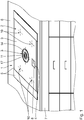
- the hob system 1 is installed in a corresponding recess in a kitchen worktop 6 by means of an installation frame 5.
- the kitchen worktop 6 is placed on a kitchen cabinet 7.
- the kitchen worktop 6 and the kitchen base cabinet 7 are components of kitchen furniture.
- the control device 4 comprises a user interface 8.
- the user interface 8 is designed in the form of a touch-sensitive screen.
- the hob 2 comprises a hob plate 9.
- the hob plate 9 is designed as a glass-ceramic plate.
- the user interface 8 is arranged on the hob plate 9.
- the hob 2 has four hotplates, which are designed as induction hotplates 10.
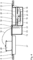
- the fume extractor device 3 comprises a cooking vapors inflow opening 11, a fan unit 12 for extracting the cooking vapors through the cooking vapors inflow opening 11 and an intake duct 13 connected to the fan unit 12 in a fluid-conducting manner for guiding the cooking vapors.
- the extractor device 3 further comprises a combination filter 15.
- the combination filter 15 is designed to filter fats and odors from the cooking vapors.
- the combination filter 15 comprises a grease filter and an odor filter for this purpose.
- the intake duct 13 extends between the inflow grille 14 and the fan unit 12 and is also referred to as a vacuum duct.
- the combination filter 15 is arranged in the suction channel 13.
- An Indian Fig. 2 The flow path 16 shown illustrates the air flow. Downstream of the fan unit 12 there is an overpressure channel (not shown) for conveying the cooking vapors.
- An odor filter in particular an activated carbon filter, is preferably arranged in the overpressure channel.
- the overpressure duct can be designed to operate the extractor device 3 in recirculation mode to return the cooking vapors to the environment and / or to operate the extractor device 3 in exhaust air mode to guide the cooking vapors, in particular through an outer wall of the building, into the environment.
- the hob system 1 is designed as an assembly unit.
- the hob 2 and the extractor device 3, in particular in the delivery state, are connected to one another to form a combination device.
- the cooking vapors inflow opening 11 overlaps a geometric center of area 17 of the hob plate 9 in a plan view.
- the cooking vapors inflow opening 11 is circular in the plan view.
- the cooking vapor inflow opening 11 is arranged centrally on the hob plate 9, in particular concentrically to the geometric centroid 17.
- the fan unit 12 comprises a fan wheel 18 and a fan motor 19 for driving the fan wheel 18 in rotation.
- the fan motor 19 is arranged at a distance from the geometric centroid 17 of the hob plate 9. A distance a GM between the geometric centroid 17 and the fan motor 19 is 120 mm.
- the fan wheel 18 is arranged at a distance from the geometric center of gravity 17 of the hob plate and at a distance from the cooking vapor inflow opening 11.
- a distance a GR between the geometric center of gravity 17 and the fan wheel 18 is 80 mm.
- the distance a ER between the cooking vapor inflow opening 11 and the fan wheel 18 is 40 mm.
- a fan axis 20 of the fan wheel 18 is oriented vertically.
- the fan axis 20 is arranged concentrically to the axis of rotation of the fan motor 19.
- the fan axis 20 is arranged from the geometric center of gravity 17 of the hob plate 9 by the distance a GA of 160 mm.
- the fan motor 19 is connected to the fan wheel 18 via a drive shaft 21 to transmit torque.
- the drive shaft 21 is arranged concentrically to the fan axis 20.
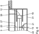
- a liquid barrier 22 is arranged upstream of the fan motor 19, in particular between the cooking vapor inflow opening 11 and the fan motor 19.
- the liquid barrier 22 completely surrounds the drive shaft 21 in the circumferential direction.
- the liquid barrier 22 is formed in one piece with the suction channel 13.
- the liquid barrier 22 protrudes above an underside 23 of the intake duct 13.
- a height h of the liquid barrier 22, in particular of an overflow collar 24, with respect to the underside 23 of the suction channel 13 is 40 mm. This reliably prevents the drive shaft 21 or the fan motor 19 from coming into contact with overflow liquid that has penetrated into the suction channel 13.
- the suction channel 13 is designed in such a way that the cooking vapors sucked in are guided in an upward direction to the fan wheel 18.
- the suction channel 13 is thus designed in such a way that the fan wheel 18 draws in the cooking vapors in a vertical direction upwards.
- the intake channel 13 extends at least in sections into an area below the fan wheel 18.
- the fan wheel 18 overlaps the intake channel 13 in a plan view. This advantageously ensures that the fan wheel 18 does not come into contact with overflow liquid either.
- the fan motor 19 is fastened to a support structure 25 which is arranged below the fan wheel 18.
- the support structure 25 is formed by the intake duct 13.
- the intake duct 13 has a not shown for this purpose Surface stiffening, in particular stiffening ribs, on.
- the stiffening ribs can be formed in one piece with the intake duct 13.
- the stiffening ribs are preferably arranged on an outside of the suction channel 13 that is not wetted by the cooking vapor flow.
- the intake channel 13 is preferably produced, in particular in a single process step, in an original molding process, for example in an injection molding process.
- the liquid barrier 22 is designed to be concavely curved in order to guide the flow with reduced resistance.
- the liquid barrier 22 is arcuate, in particular a circular arc.
- the liquid barrier 22 has a flow guide element 26.
- the flow guide element 26 is designed to split the cooking vapor flow with reduced resistance.
- the flow guide element 26 thus ensures a particularly low-loss flow around the liquid barrier 22.
- the flow guide element 26 is funnel-shaped and in a top view, not shown, the flow guide element 26 is elliptical, in particular with an aspect ratio of at least 5. Because the fan motor 19 is fastened to the support structure 25 exclusively below the fan wheel 18, a disruptive influence from the fan motor 19 induced magnetic fields on electronics arranged above the fan wheel 18 can be avoided. In particular, vibrations transmitted to an electronics housing 27 can be reduced. The fastening of the fan motor 19 to the support structure 25 at a distance from the electronics ensures damping of corresponding vibrations.
- the electronics can be heating and / or control electronics for the hobs 2.
- the heating electronics are designed to operate induction cooking zones 10.
- the control electronics are part of the control device 4.
- the mode of operation of the hob system 1, the hob 2 and the extractor device 3 is as follows:
- the control device 4 is in an energy-transmitting connection with the hob 2 and the extractor device 3.
- one or more of the induction hotplates 10 can be activated.
- Food 29 arranged on the respective induction cooking zones 10 is heated and cooking vapors are generated.
- the extractor device 3 is activated by means of the control device 4, with electrical power being provided to the fan motor 19.
- the fan motor 19 causes the fan wheel 18 to rotate about the fan axis 20.
- the cooking vapors are sucked in from an area above the food 29 along the flow path 16 through the cooking vapor inflow opening 11 into the suction channel 13. Fats and odors are filtered out of the cooking vapors in the combination filter 15.
- the cooking vapors are conducted along the suction channel 13 and sucked in in a vertical direction upwards to the fan wheel 18, in particular into a fan housing 30 of the fan unit 12.
- Cooking vapors flow around the liquid barrier 22 in a horizontal plane on both sides of the fan axis 20. Because the liquid barrier 22 has the flow guide element 26, this flow around can take place with particularly low resistance.
- the concave design of the liquid barrier 22 also promotes the flow-efficient suction of cooking vapors in the upward direction of the fan wheel 18.
- the fan wheel 18 and the fan motor 19 are arranged at a distance from the geometric center of gravity 17 of the hob plate 9 and at a distance from the cooking vapor inflow opening 11, they are shielded from the overflow liquid entering through the cooking vapor inflow opening 11.
- the suction of the cooking vapors in the upward direction protects in particular the fan wheel 18 from coming into contact with overflow liquid.
- the penetration of the overflow liquid to the fan motor 19 and to the drive shaft 21 is prevented by the liquid barrier 22.
- the hob system 1, in particular the extractor device 3, is therefore particularly robust and can be operated safely.
- the extractor device 3 comprises a fan attachment 31 for attaching the fan unit 12 to the hob plate 9.
- the suction channel 13 is designed in this way for fluid-conducting connection of the cooking vapor inflow opening 11 to the fan unit 12 is that the cooking vapors are sucked into the fan unit 12 in a downward direction.
- the fan fastening 31 is designed in the form of an angle, in particular an angled sheet metal, in particular a metal sheet.
- the fan fastening 31 is glued to the hob plate 9.
- the hob plate 9 is designed as a glass-ceramic plate.
- the extractor device has a liquid barrier 22 formed by the intake duct 13 and arranged upstream of the fan unit 12.
- the fan unit 12 is fastened to the hob plate 9 by means of the fan fastening 31, the transmission of vibrations, which occur during operation of the fan motor 19 and the fan wheel 18, to the electronics for controlling and / or heating the hob can be reduced.
- the hob plate 9 which is usually designed to be particularly rigid, the excitation of vibrations on the hob system 1, in particular on the electronics housing 27, can be avoided.
- the hob system 1 is therefore particularly quiet and robust in operation.
- the fan fastening 31 preferably has at least one vibration damping element.
- the vibration damping element can for example comprise a rubber-elastic material.
- the hob system 1 shown corresponds to the mode of operation of the hob system 1 according to the exemplary embodiment described above.
- the suction channel 13 extending between the cooking vapors inflow opening 11 and the fan unit 12 is designed in such a way that the cooking vapors flow into the fan unit 12 in both the upward and downward directions.
- the intake channel 13 has two intake channel sections 32, 33 overlapping the fan wheel 18 in a plan view, the first intake channel section 32 being above the Fan wheel 18 is arranged and wherein the second intake channel section 33 is arranged below the fan wheel 18. The feeding of the cooking vapors to the fan wheel 18 can thus take place in a particularly flow-efficient manner.
- the fan motor 19 is attached to a liquid barrier 22 which is fastened to the support structure 25.
- the fan motor 19 is placed on the liquid barrier 22 and is fastened to the support structure 25 by means of this.
- the support structure 25 is designed in the form of the intake duct 13.
- the intake duct 13 is attached to an underside 34 of the kitchen worktop 6 by means of the fan fastening 31.
- the fan unit 12, in particular the fan wheel 18 and the fan motor 19, are thus fastened to the underside 34 by means of the fan fastening 31. This enables a particularly robust, rigid and low-vibration fastening of the fan unit 12 during operation.
- the fan wheel 18 is detachably connected to the fan motor 19.
- a reversibly releasable fan clutch 35 is provided between the fan wheel 18 and the fan motor 19 for this purpose.
- the mode of operation of the hob system 1 according to that shown in FIG Fig. 5
- the illustrated embodiment corresponds to the mode of operation of the hob system 1 according to the embodiments described above.
- a further exemplary embodiment of a hob system 1 of a fan fastening 31 is described.
- the fan fastening 31 is designed to rest on the kitchen worktop 6 from above.
- the hob system 1 can be easily inserted from above into a corresponding recess in the kitchen worktop 6.
- the hob plate 9 rests on the fan fastening 31 from above.
- the fan fastening 31 is preferably connected to the hob plate 9, in particular glued to it.
- the assembly of the hob system 1 on the kitchen worktop 6 is made particularly simple by connecting the fan attachment 31 to the hob plate 9. Alternatively, there is no, in particular no direct, connection between the fan fastening 31 and the hob plate 9.
- the mode of operation of the hob system 1 according to that shown in FIG Fig. 6
- the illustrated embodiment corresponds to the mode of operation of the hob system 1 according to the embodiments described above.
- the fan motor 19 is attached to a support structure 25 arranged below the fan wheel 18, a particularly robust, low-vibration and low-noise attachment can be ensured during operation.
- the suction channel 13 By designing the suction channel 13 in such a way that the cooking vapors are sucked into the fan unit 12 in an upward direction, the fan unit 12, in particular the fan motor 19, is particularly reliably protected from overflow liquids.
- the fastening of the fan unit 12 by means of the fan fastening 31 on the hob plate 9 or on the kitchen worktop 6 enables the fan unit 12 to be mounted in a rigid, robust and low-vibration manner.
Abstract
Eine Dunstabzugsvorrichtung (3) zum Abzug von Kochdünsten nach unten umfasst mindestens eine Kochdunst-Einströmöffnung (11), mindestens eine Lüftereinheit (12) zum Ansaugen der Kochdünste, mit einem Lüfterrad (18), und einem Lüftermotor (19) zum Drehantreiben des Lüfterrads (18), und einen Ansaugkanal (13) zum fluidleitenden Verbinden der mindestens einen Kochdunst-Einströmöffnung (11) mit der mindestens einen Lüftereinheit (12), welcher sich zum Ansaugen der Kochdünste in die mindestens eine Lüftereinheit (12) in Richtung nach oben zumindest abschnittsweise unterhalb des Lüfterrads (18) erstreckt, wobei eine Befestigung des Lüftermotors (19) an einer unterhalb des Lüfterrads (18) angeordneten Tragstruktur (25) erfolgt.A fume extractor device (3) for extracting cooking vapors downwards comprises at least one cooking vapors inflow opening (11), at least one fan unit (12) for sucking in cooking vapors, with a fan wheel (18), and a fan motor (19) for rotating the fan wheel ( 18), and a suction channel (13) for fluid-conducting connection of the at least one cooking vapor inflow opening (11) with the at least one fan unit (12), which is at least partially in an upward direction to suck in cooking vapors into the at least one fan unit (12) extends below the fan wheel (18), the fan motor (19) being fastened to a support structure (25) arranged below the fan wheel (18).
Description
Der Inhalt der deutschen Patentanmeldung
Die Erfindung betrifft eine Dunstabzugsvorrichtung zum Abzug von Kochdünsten nach unten. Ferner betrifft die Erfindung ein Kochfeldsystem mit einer derartigen Dunstabzugsvorrichtung.The invention relates to an extractor device for extracting cooking vapors downwards. The invention also relates to a cooktop system with an extractor device of this type.
Aus der
Ein Kochfeldsystem mit einer Dunstabzugsvorrichtung und mehreren Kochfeldern ist ferner bekannt aus der
Es ist eine Aufgabe der Erfindung, ein Kochfeldsystem zum Einsetzen in eine Küchenarbeitsplatte mit einer Dunstabzugsvorrichtung zum Abzug von Kochdünsten nach unten zu verbessern.It is an object of the invention to improve a hob system for insertion in a kitchen worktop with an extractor device for extracting cooking vapors downwards.
Diese Aufgabe wird durch ein Kochfeldsystem mit den Merkmalen des Anspruchs 1 gelöst. Erfindungsgemäß wurde erkannt, dass ein Kochfeldsystem mit einer Dunstabzugsvorrichtung zum Abzug von Kochdünsten nach unten mit mindestens einer Lüftereinheit zum Ansaugen der Kochdünsten und einem Ansaugkanal, welcher sich, insbesondere zum Ansaugen der Kochdünste in die mindestens eine Lüftereinheit in Richtung nach oben, zumindest abschnittsweise in einen Bereich unterhalb des Lüfterrads erstreckt und somit einen besonders sicheren Betrieb der Dunstabzugsvorrichtung gewährleistet, besonders robust und geräuscharm betrieben werden kann, wenn die Befestigung eines Lüftermotors der Lüftereinheit an einer unterhalb eines Lüfterrads der Lüftereinheit angeordneten Tragstruktur erfolgt. Durch die Befestigung des Lüftermotors an der unterhalb des Lüfterrads angeordneten Tragstruktur kann eine Entkoppelung des Lüftermotors von oberhalb des Lüftermotors angeordneten Bauteilen, insbesondere von einem Kochstellengehäuse, insbesondere einem Gehäuse für die Kochfeldbeheizung oder -steuerung, erfolgen. Eine Übertragung mechanisch belastender Vibrationen von dem Lüftermotor auf oberhalb des Lüftermotors angeordnete Elektronik-Bauteile kann reduziert werden. Eine Geräuschanregung durch ein in Vibration versetztes, oberhalb des Lüftermotors angeordnetes und üblicherweise dem Benutzer zugewandtes Gehäuse kann somit vermeiden werden. Durch die Ausbildung des Ansaugkanals derart, dass die Kochdünste in Richtung nach oben in die Lüftereinheit angesaugt werden, ist der Lüftermotor zuverlässig vor Überlaufflüssigkeiten geschützt, wodurch die Dunstabzugsvorrichtung besonders robust im Betrieb ist.This object is achieved by a hob system with the features of
Die Tragstruktur kann insbesondere vollständig unterhalb des Lüfterrads angeordnet sein. Sie kann auch in Vertikalrichtung mit dem Lüfterrad überlappen.The support structure can in particular be arranged completely below the fan wheel. It can also overlap with the fan wheel in the vertical direction.
Gemäß einem Aspekt der Erfindung sind der Lüftermotor und das Lüfterrad, insbesondere die gesamte Lüftereinheit, an der unterhalb des Lüfterrads angeordneten Tragstruktur befestigt. Auch eine Übertragung von Vibrationen, für welche die Rotation des Lüfterrads ursächlich ist, auf oberhalb des Lüftermotors angeordnete Komponenten, kann somit vermieden werden.According to one aspect of the invention, the fan motor and the fan wheel, in particular the entire fan unit, are fastened to the support structure arranged below the fan wheel. Also a transmission of vibrations, for which the rotation of the fan wheel is the cause, on components arranged above the fan motor, can thus be avoided.
Vorzugsweise ist der Lüftermotor, insbesondere die mindestens eine Lüftereinheit, ausschließlich an der unterhalb des Lüfterrads angeordneten Tragstruktur befestigt. Der Lüftermotor kann hierzu von oben auf der Tragstruktur aufliegen. Der Lüftermotor kann insbesondere auf die Tragstruktur aufgesetzt sein. Die Befestigung des Lüftermotors an der Tragstruktur kann formschlüssig und/oder kraftschlüssig, insbesondere mittels einer Bolzenverbindung, insbesondere einer Schraubverbindung oder einer Nietverbindung, erfolgen. Die Befestigung des Lüftermotors an der Tragstruktur ist vorzugsweise derart ausgebildet, dass die Gewichtskraft des Lüftermotors überwiegend, also zu einem Anteil von mehr als 50 %, insbesondere vollständig, in Form von Druckkräften auf die Tragstruktur übertragen wird.The fan motor, in particular the at least one fan unit, is preferably fastened exclusively to the support structure arranged below the fan wheel. For this purpose, the fan motor can rest on the support structure from above. The fan motor can in particular be placed on the support structure. The fan motor can be fastened to the support structure in a form-fitting and / or force-fitting manner, in particular by means of a bolt connection, in particular a screw connection or a rivet connection. The attachment of the fan motor to the support structure is preferably designed in such a way that the weight of the fan motor is predominantly, i.e. in a proportion of more than 50%, in particular completely, transmitted to the support structure in the form of compressive forces.
Die Verbindung zwischen dem Lüftermotor und der Tragstruktur ist somit besonders robust und wirtschaftlich herstellbar.The connection between the fan motor and the support structure can thus be produced in a particularly robust and economical manner.
Der Lüftermotor kann insbesondere zumindest teilweise, insbesondere vollständig, oberhalb der Tragstruktur angeordnet sein.The fan motor can in particular be arranged at least partially, in particular completely, above the support structure.
Alternativ hierzu kann der Lüftermotor auch zumindest teilweise, insbesondere vollständig, unterhalb der Tragstruktur angeordnet sein.As an alternative to this, the fan motor can also be arranged at least partially, in particular completely, below the support structure.
Die Tragstruktur kann sich, insbesondere in Draufsicht, über den Lüftermotor hinaus erstrecken. Sie kann eine Lastabtragung in ein Küchenmöbel, insbesondere einen Unterschrank, in eine Wand oder in eine Küchenarbeitsplatte ermöglichen.The support structure can extend beyond the fan motor, in particular when viewed from above. It can enable load transfer in kitchen furniture, in particular a base cabinet, in a wall or in a kitchen worktop.
Gemäß einem Aspekt der Erfindung ist der Ansaugkanal derart ausgebildet, dass zumindest ein Teil der Kochdünste in Richtung nach oben in die Lüftereinheit angesaugt wird. Der Anteil der nach oben angesaugten Kochdünste beträgt vorzugsweise mindestens 25 %, insbesondere mindestens 50 %, insbesondere mindestens 70 %, insbesondere 100 %. Der verbleibende Anteil der in die Lüftereinheit angesaugten Kochdünste kann beispielsweise in Richtung nach unten in diese angesaugt werden. Durch die zumindest anteilige Ansaugung der Kochdünste nach oben, steht ein unterhalb der Lüftereinheit angeordnetes Volumen des Ansaugkanals zur Aufnahme von Überlaufflüssigkeit zur Verfügung. Der Lüftermotor ist somit besonders zuverlässig vor Überlaufflüssigkeiten geschützt, welche über die mindestens eine Kochdunst-Einströmöffnung in den Ansaugkanal vordringen können und bei einem Kontakt mit den stromführenden Komponenten des Lüftermotors zu einer Gefährdung des Benutzers und einer Beschädigung der Dunstabzugsvorrichtung führen können. Durch die zumindest teilweise Ansaugung der Kochdünste nach oben ist die Dunstabzugsvorrichtung besonders sicher und robust im Betrieb.According to one aspect of the invention, the suction channel is designed in such a way that at least some of the cooking vapors are sucked into the fan unit in an upward direction. The proportion of cooking vapors sucked in upwards is preferably at least 25%, in particular at least 50%, in particular at least 70%, in particular 100%. The remaining portion of the cooking vapors sucked into the fan unit can be sucked into the fan unit in a downward direction, for example. Due to the at least partial upward suction of the cooking vapors, a volume of the suction channel arranged below the fan unit is available for receiving overflow liquid. The fan motor is thus particularly reliably protected against overflow liquids which can penetrate into the intake duct via the at least one cooking vapor inflow opening and can endanger the user and damage the extractor device if they come into contact with the current-carrying components of the fan motor. As the cooking vapors are at least partially sucked upwards, the extractor device is particularly safe and robust in operation.
Eine weitere, insbesondere unabhängig von der vorstehend beschriebenen Dunstabzugsvorrichtung schützenswerte, Idee betrifft eine Dunstabzugsvorrichtung mit mindestens einer Kochdunst-Einströmöffnung und mindestens einer Lüftereinheit, welche einen Lüftermotor und ein reversibel lösbar mit dem Lüftermotor verbundenes Lüfterrad umfasst. Vorzugsweise wird die zuvor beschriebene Dunstabzugsvorrichtung mit den Merkmalen dieser Dunstabzugsvorrichtung weitergebildet und anders herum. Zwischen dem Lüfterrad und dem Lüftermotor kann eine lösbare Lüfterkupplung vorgesehen sein. Vorteilhaft wird hierdurch erreicht, dass das Lüfterrad zu Reinigungszwecken aus der Dunstabzugsvorrichtung entnommen werden kann. Hinsichtlich der Details zur Ausbildung der Lüfterkupplung wird auf die
Vorzugsweise kann zur einfacheren Entnahme des Lüfterrads, insbesondere um die Entnahme erst zu ermöglichen, ein Teil eines Lüftergehäuses der Lüftereinheit aus der Dunstabzugsvorrichtung, insbesondere durch die Kochdunst-Einströmöffnung, entnommen werden. Das Lüftergehäuse kann im Bereich einer Gehäuse-Einströmöffnung und/oder einer Gehäuse-Ausströmöffnung ein Schutzgitter und/oder mindestens ein Luftleitelement und/oder einen Filtersitz für einen Filter, insbesondere einen Fettfilter, aufweisen. Das Schutzgitter und/oder das mindestens eine Luftleitelement und/oder der Filter sind vorzugsweise, insbesondere zur Entnahme des Lüfterrads aus dem Lüftergehäuse, von dem Lüftergehäuse abnehmbar. Die Reinigbarkeit der Dunstabzugsvorrichtung wird hierdurch nochmals verbessert.For easier removal of the fan wheel, in particular to enable removal in the first place, a part of a fan housing of the fan unit can be removed from the extractor device, in particular through the cooking vapor inflow opening. The fan housing can have a protective grille and / or at least one air guide element and / or a filter seat for a filter, in particular a grease filter, in the area of a housing inflow opening and / or a housing outflow opening. The protective grille and / or the at least one air guiding element and / or the filter are preferably removable from the fan housing, in particular in order to remove the fan wheel from the fan housing. This further improves the cleanability of the extractor device.
Das Lüfterrad kann auch durch eine reversibel verschließbare Entnahmeöffnung des Ansaugkanals und/oder eines Überdruckkanals aus der Dunstabzugsvorrichtung entnehmbar sein. Zum reversiblen Verschluss der Entnahmeöffnung können der Ansaugkanal und/oder der Überdruckkanal einen Entnahmedeckel aufweisen. Die Entnahmeöffnung kann zur Entnahme des Lüfterrads nach unten ausgebildet sein. Vorzugsweise ist die Entnahmeöffnung an einem Boden des Ansaugkanals und/oder des Überdruckkanals angeordnet. Vorzugsweise ist die Entnahmeöffnung auch zur Entnahme eines Filters, insbesondere eines Geruchsfilters, insbesondere eines Aktivkohlefilters, ausgebildet, welcher insbesondere im Überdruckkanal vorgesehen ist.The fan wheel can also be removed from the extractor device through a reversibly closable removal opening in the intake duct and / or an overpressure duct. For the reversible closure of the removal opening, the suction channel and / or the overpressure channel can have a removal cover. The removal opening can be designed to remove the fan wheel downwards. The removal opening is preferably arranged on a bottom of the suction channel and / or the overpressure channel. The removal opening is preferably also for removal a filter, in particular an odor filter, in particular an activated carbon filter, which is provided in particular in the overpressure channel.
Gemäß einem weiteren Aspekt der Erfindung ist die Kochdunst-Einströmöffnung im Querschnitt rund, insbesondere elliptisch, insbesondere kreisförmig, oder polygonal, insbesondere rechteckförmig. Ein Seitenverhältnis des Querschnitts beträgt vorzugsweise mindestens 1,5, insbesondere mindestens 2, insbesondere mindestens 3.According to a further aspect of the invention, the cooking vapor inflow opening is round in cross section, in particular elliptical, in particular circular, or polygonal, in particular rectangular. An aspect ratio of the cross section is preferably at least 1.5, in particular at least 2, in particular at least 3.
Gemäß einem weiteren Aspekt der Erfindung ist der Lüftermotor durch die Kochdunst-Einströmöffnung und/oder die Entnahmeöffnung für das Lüfterrad und/oder durch einen Boden des Ansaugkanals und/oder des Überdruckkanals aus der Dunstabzugsvorrichtung reversibel entnehmbar. Eine entsprechende Entnahme des Lüftermotors ist durch die Befestigung des Lüftermotors an der unterhalb des Lüfterrads angeordneten Tragstruktur in besonders einfacher Weise möglich. Hierdurch wird die Entnahme des Lüftermotors zu Wartungszwecken und/oder zum Ersatz durch einen Austauschmotor in wirtschaftlicher Weise ermöglicht. Die Befestigung des Lüftermotors kann hierzu reversibel lösbar ausgebildet sein.According to a further aspect of the invention, the fan motor can be reversibly removed from the fume extractor device through the cooking vapors inflow opening and / or the removal opening for the fan wheel and / or through a bottom of the intake duct and / or the overpressure duct. A corresponding removal of the fan motor is possible in a particularly simple manner by fastening the fan motor to the support structure arranged below the fan wheel. This enables the fan motor to be removed economically for maintenance purposes and / or to replace it with a replacement motor. For this purpose, the fastening of the fan motor can be designed to be reversibly detachable.
Zum Ansaugen der Kochdünste in die Lüftereinheit nach oben erstreckt sich der Ansaugkanal zumindest abschnittsweise unterhalb des Lüfterrads. Vorzugsweise überlappt und/oder überdeckt das Lüfterrad den Ansaugkanal in einer Draufsicht zumindest abschnittsweise.In order to suck in the cooking vapors upwards into the fan unit, the suction channel extends at least in sections below the fan wheel. The fan wheel preferably overlaps and / or covers the intake duct at least in sections in a plan view.
Die mindestens eine Lüftereinheit ist vorzugsweise als Radiallüfter ausgebildet. Die mindestens eine Lüftereinheit kann auch als Axiallüfter und/oder als Querstromlüfter ausgebildet sein.The at least one fan unit is preferably designed as a radial fan. The at least one fan unit can also be designed as an axial fan and / or as a cross-flow fan.
Gemäß einem weiteren Aspekt der Erfindung ist die Tragstruktur durch den Ansaugkanal ausgebildet und/oder insbesondere einteilig, insbesondere stoffschlüssig, mit dem Ansaugkanal verbunden. Dadurch, dass die Tragstruktur durch den Ansaugkanal ausgebildet ist, kann die Struktur des Ansaugkanals besonders effizient genutzt werden. Die Dunstabzugsvorrichtung ist somit besonders bauraumsparend realisierbar und wirtschaftlich herstellbar.According to a further aspect of the invention, the support structure is formed by the intake channel and / or in particular is connected to the intake channel in one piece, in particular in a materially bonded manner. Because the support structure is formed by the intake channel, the structure of the intake channel can be used particularly efficiently. The extractor device can thus be implemented in a particularly space-saving manner and can be manufactured economically.
Die Tragstruktur kann auch als Bestandteil eines Gehäuses des Kochfeldsystems ausgebildet oder mit diesem verbunden sein. In diesem Fall ist bevorzugt vorgesehen, die Tragstruktur durch Entkopplungsmittel, insbesondere vibrationsdämpfende Mittel, von anderen Bereichen des Gehäuses zu entkoppeln.The support structure can also be designed as part of a housing of the hob system or connected to it. In this case, provision is preferably made for the support structure to be decoupled from other areas of the housing by decoupling means, in particular vibration-damping means.
Die Tragstruktur kann auch durch ein vom Kochfeldsystem getrenntes, separates Element gebildet sein. Sie kann beispielsweise an einem Küchenschrank, einer Wand oder einer Küchenarbeitsplatte angeordnet, insbesondere in kraftübertragender Weise verbunden sein.The support structure can also be formed by a separate element that is separate from the hob system. It can be arranged, for example, on a kitchen cabinet, a wall or a kitchen worktop, in particular connected in a force-transmitting manner.
Die Tragstruktur kann als Versteifungselement ausgebildet sein oder ein oder mehrere Versteifungselemente, insbesondere Profilleisten, umfassen.The support structure can be designed as a stiffening element or comprise one or more stiffening elements, in particular profile strips.
Gemäß einem weiteren Aspekt der Erfindung ist zwischen der Kochdunst-Einströmöffnung und dem Lüftermotor, insbesondere stromaufwärts des Lüferrads, eine Flüssigkeitssperre angeordnet. Die Flüssigkeitssperre kann in dem Ansaugkanal angeordnet sein. Die Flüssigkeitssperre begrenzt zumindest abschnittsweise ein Flüssigkeitsreservoir zur Aufnahme von Überlaufflüssigkeit. Vorzugsweise wird das Flüssigkeitsreservoir durch eine reversibel aus der Dunstabzugsvorrichtung entnehmbare Flüssigkeitswanne gebildet. Die Flüssigkeitswanne ist vorzugsweise durch die Kochdunst-Einströmöffnung und/oder die Entnahmeöffnung für das Lüfterrad, welche insbesondere an einem Boden des Ansaugkanals und/oder des Überdrucckanals angeordnet ist, entnehmbar. Durch die Flüssigkeitssperre wird durch die Kochdunst-Einströmöffnung in die Dunstabzugsvorrichtung eindringende Überlaufflüssigkeit am Vordringen in Richtung der Lüftereinheit, insbesondere des Lüftermotors, gehindert. Das Flüssigkeitsreservoir weist vorzugsweise ein Fassungsvermögen von mindestens 100 ml, insbesondere mindestens 250 ml, insbesondere mindestens 500 ml, auf.According to a further aspect of the invention, a liquid barrier is arranged between the cooking vapor inflow opening and the fan motor, in particular upstream of the fan wheel. The liquid barrier can be arranged in the suction channel. The liquid barrier delimits, at least in sections, a liquid reservoir for receiving overflow liquid. Preferably, the liquid reservoir is through a Formed reversibly removable liquid tub from the extractor device. The liquid tub can preferably be removed through the cooking vapor inflow opening and / or the removal opening for the fan wheel, which is arranged in particular on a bottom of the suction channel and / or the overpressure channel. The liquid barrier prevents overflow liquid penetrating into the extractor device through the cooking vapor inflow opening from advancing in the direction of the fan unit, in particular the fan motor. The liquid reservoir preferably has a capacity of at least 100 ml, in particular at least 250 ml, in particular at least 500 ml.
Gemäß einem weiteren Aspekt der Erfindung umschließt die Flüssigkeitssperre eine Lüfterachse des Lüfterrads in Umfangsrichtung vollständig, das heißt um 360 °. Die Flüssigkeitssperre kann eine Antriebswelle, welche das Lüfterrad drehmomentübertragend mit dem Lüftermotor verbindet, in Umfangsrichtung umschließen. Vorteilhaft wird hierdurch erreicht, dass der Lüftermotor auch bei einer Umströmung der Drehachse von den Kochdünsten zuverlässig vor Überlaufflüssigkeiten geschützt ist.According to a further aspect of the invention, the liquid barrier completely encloses a fan axis of the fan wheel in the circumferential direction, that is to say by 360 °. The liquid barrier can enclose a drive shaft, which connects the fan wheel to the fan motor in a torque-transmitting manner, in the circumferential direction. This advantageously means that the fan motor is reliably protected from overflow liquids even when cooking vapors flow around the axis of rotation.
Ein oberer Rand der Flüssigkeitssperre, welcher für das Fassungsvermögen des Flüssigkeitsreservoirs ausschlaggebend ist, wird auch als Überlaufkragen bezeichnet. Gemäß einem Aspekt der Erfindung beträgt eine Höhe h des Flüssigkeitsreservoirs, insbesondere eines vertikalen Abstands des Überlaufkragens von einer Unterseite des Ansaugkanals mindestens 5 mm, insbesondere mindestens 10 mm, insbesondere mindestens 20 mm, insbesondere mindestens 40 mm.An upper edge of the liquid barrier, which is decisive for the capacity of the liquid reservoir, is also referred to as an overflow collar. According to one aspect of the invention, a height h of the liquid reservoir, in particular a vertical distance of the overflow collar from an underside of the suction channel, is at least 5 mm, in particular at least 10 mm, in particular at least 20 mm, in particular at least 40 mm.
Gemäß einem weiteren Aspekt der Erfindung umfasst die Dunstabzugsvorrichtung mindestens einen Sensor zum Erfassen eines Flüssigkeitsfüllstands in dem Flüssigkeitsreservoir. Der Sensor kann als kapazitiver Sensor und/oder als Leitfähigkeitssensor und/oder als optischer Sensor ausgebildet sein. Vorzugsweise steht der Sensor mit einer Steuereinrichtung in Signalverbindung. Die Steuereinrichtung ist vorzugsweise dazu ausgebildet, beim Erreichen eines Grenzfüllstands der Flüssigkeit in dem Flüssigkeitsreservoir ein Signal bereitzustellen, welches die Abschaltung der Dunstabzugsvorrichtung, insbesondere des Lüftermotors, und/oder die Ausgabe eines akustischen und/oder optischen Warnsignals bewirkt.According to a further aspect of the invention, the extractor device comprises at least one sensor for detecting a liquid fill level in the liquid reservoir. The sensor can be designed as a capacitive sensor and / or as a conductivity sensor and / or as an optical sensor. The sensor is preferably in signal connection with a control device. The control device is preferably designed to provide a signal when a limit level of the liquid in the liquid reservoir is reached, which causes the extractor device, in particular the fan motor, to be switched off and / or an acoustic and / or optical warning signal to be output.
Gemäß einem weiteren Aspekt der Erfindung weist die Flüssigkeitssperre mindestens 1, insbesondere mindestens 2, Strömungsleitelemente auf. Das Strömungsleitelement kann als Leitblech und/oder als Leitprofil ausgebildet sein. Vorzugsweise ist eine Haupterstreckungsebene des mindestens einen Strömungsleitelements parallel zu der Drehachse orientiert. Das Strömungsleitelement kann als Strömungsteiler zum strömungseffizienten Aufteilen der Kochdunstströmung, insbesondere zur beidseitigen Umströmung der Lüfterachse und/oder der Antriebswelle, ausgebildet sein. Eine verlustbehaftete Wirbelbildung beim Umströmen der Flüssigkeitssperre kann somit vermieden werden.According to a further aspect of the invention, the liquid barrier has at least 1, in particular at least 2, flow guide elements. The flow guide element can be designed as a guide plate and / or as a guide profile. A main plane of extent of the at least one flow guide element is preferably oriented parallel to the axis of rotation. The flow guide element can be designed as a flow divider for the flow-efficient splitting of the cooking vapor flow, in particular for the flow around both sides of the fan axis and / or the drive shaft. A lossy vortex formation when flowing around the liquid barrier can thus be avoided.
Gemäß einem weiteren Aspekt der Erfindung umfasst die Tragstruktur mindestens ein Strömungsleitelement gemäß der vorstehenden Beschreibung.According to a further aspect of the invention, the support structure comprises at least one flow guide element according to the description above.
Gemäß einem weiteren Aspekt der Erfindung ist die Flüssigkeitssperre zur widerstandsreduzierten Strömungsführung zumindest bereichsweise konkav gekrümmt ausgebildet. Gemäß einem Aspekt der Erfindung überlappt das Lüfterrad in einer Draufsicht die Flüssigkeitssperre. Die konkave Krümmung der Flüssigkeitssperre kann zum Umlenken der Kochdunstströmung in Richtung des Lüfterrads nach oben ausgebildet sein. Die Umlenkung der Kochdunstströmung in Richtung des Lüfterrads kann somit besonders strömungseffizient erfolgen.According to a further aspect of the invention, the liquid barrier is designed to be concavely curved, at least in some areas, for flow guidance with reduced resistance. According to one aspect of the invention, the fan wheel overlaps the liquid barrier in a plan view. The concave curvature of the liquid barrier can be used to redirect the flow of cooking vapors be formed in the direction of the fan wheel upwards. The deflection of the cooking vapor flow in the direction of the fan wheel can thus take place in a particularly flow-efficient manner.
Gemäß einem weiteren Aspekt der Erfindung ist die Flüssigkeitssperre ein Bestandteil der Tragstruktur, wobei der Lüftermotor an der Flüssigkeitssperre befestigt ist. Die Struktur der Flüssigkeitssperre kann somit zusätzlich zur mechanischen Befestigung des Lüftermotors verwendet werden. Die Dunstabzugsvorrichtung kann somit besonders bauraumsparend und wirtschaftlich umgesetzt werden.According to a further aspect of the invention, the liquid barrier is part of the support structure, the fan motor being attached to the liquid barrier. The structure of the liquid barrier can thus also be used for mechanical fastening of the fan motor. The extractor device can thus be implemented in a particularly space-saving and economical manner.
Gemäß einem weiteren Aspekt der Erfindung überragt der Ansaugkanal das Lüfterrad um mindestens 20 mm, insbesondere mindestens 30 mm, insbesondere mindestens 40 mm, insbesondere mindestens 60 mm, nach unten. Hierdurch kann ein besonders großer Strömungsquerschnitt zum Ansaugen der Kochdünste bereitgestellt werden, wodurch die Ansaugung besonders strömungseffizient ist. Zudem kann das Fassungsvermögen eines Flüssigkeitsreservoirs ausreichend groß dimensioniert werden.According to a further aspect of the invention, the intake duct projects downward beyond the fan wheel by at least 20 mm, in particular at least 30 mm, in particular at least 40 mm, in particular at least 60 mm. As a result, a particularly large flow cross-section can be provided for sucking in the cooking vapors, whereby the suction is particularly flow-efficient. In addition, the capacity of a liquid reservoir can be dimensioned to be sufficiently large.
Gemäß einem weiteren Aspekt der Erfindung überragt der Lüftermotor den Ansaugkanal um mindestens 20 mm, insbesondere mindestens 30 mm, insbesondere mindestens 40 mm, insbesondere mindestens 60 mm, nach unten. Eine besonders bauraumsparende Ausbildung der Dunstabzugsvorrichtung wird somit ermöglicht. Alternativ kann der Ansaugkanal den Lüftermotor um mindestens 20 mm, insbesondere mindestens 30 mm, insbesondere mindestens 40 mm, insbesondere mindestens 60 mm, nach unten überragen. Hierdurch wird der Schutz vor Überlaufflüssigkeiten verbessert.According to a further aspect of the invention, the fan motor projects downward beyond the intake duct by at least 20 mm, in particular at least 30 mm, in particular at least 40 mm, in particular at least 60 mm. A particularly space-saving design of the extractor device is thus made possible. Alternatively, the intake duct can protrude downward beyond the fan motor by at least 20 mm, in particular at least 30 mm, in particular at least 40 mm, in particular at least 60 mm. This improves the protection against overflow liquids.
Gemäß einem weiteren Aspekt der Erfindung ist die Lüfterachse des Lüfterrads vertikal orientiert. Die vertikale Orientierung der Lüfterachse gewährleistet in Kombination mit der Ansaugung in vertikaler Richtung nach oben den besonders zuverlässigen Schutz des Lüftermotors vor Überlaufflüssigkeiten. Zudem kann die Dunstabzugsvorrichtung hierdurch besonders bauraumsparend ausgebildet werden. Eine vertikale Erstreckung der Dunstabzugsvorrichtung zwischen der Kochdunst-Einströmöffnung und der Unterseite des Ansaugkanals beträgt vorzugsweise maximal 250 mm, insbesondere maximal 200 mm, insbesondere maximal 150 mm, insbesondere maximal 100 mm.According to a further aspect of the invention, the fan axis of the fan wheel is oriented vertically. The vertical orientation of the fan axis, in combination with the suction in the vertical direction upwards, ensures particularly reliable protection of the fan motor against overflow liquids. In addition, the extractor device can hereby be designed to be particularly space-saving. A vertical extension of the extractor device between the cooking vapor inflow opening and the underside of the suction channel is preferably a maximum of 250 mm, in particular a maximum of 200 mm, in particular a maximum of 150 mm, in particular a maximum of 100 mm.
Gemäß einem weiteren Aspekt der Erfindung sind eine Lüfterachse des Lüfterrads und/oder das Lüfterrad und/oder der Lüftermotor in einer Draufsicht beabstandet von der Kochdunst-Einströmöffnung und/oder einem geometrischen Flächenschwerpunkt einer Kochstellenplatte angeordnet. Die Kochdunst-Einströmöffnung ist vorzugsweise als eine Ausnehmung der Kochstellenplatte ausgebildet. Die Kochstellenplatte überlappt in einer Draufsicht vorzugsweise den Lüftermotor und/oder das Lüfterrad teilweise, insbesondere unvollständig oder vollständig. Vorteilhaft wird hierdurch erreicht, dass der Lüftermotor und/oder das Lüfterrad besonders zuverlässig vor Überlaufflüssigkeiten geschützt sind.According to a further aspect of the invention, a fan axis of the fan wheel and / or the fan wheel and / or the fan motor are arranged in a plan view at a distance from the cooking vapor inflow opening and / or a geometric centroid of a hotplate. The cooking vapor inflow opening is preferably designed as a recess in the hotplate. In a top view, the hotplate preferably partially overlaps the fan motor and / or the fan wheel, in particular incompletely or completely. This advantageously means that the fan motor and / or the fan wheel are particularly reliably protected from overflow liquids.
Ein Abstand zwischen dem geometrischen Flächenschwerpunkt der Kochstellenplatte und der Lüfterachse und/oder dem Lüfterrad und/oder dem Lüftermotor beträgt in horizontaler Richtung vorzugsweise mindestens 5 mm, insbesondere mindestens 10 mm, insbesondere mindestens 20 mm, insbesondere mindestens 40 mm. Ein Abstand zwischen der Kochdunst-Einströmöffnung und der Lüfterachse und/oder dem Lüfterrad und/oder dem Lüftermotor beträgt in horizontaler Richtung vorzugsweise mindestens 5 mm, insbesondere mindestens 10 mm, insbesondere mindestens 20 mm, insbesondere mindestens 40 mm.A distance between the geometric centroid of the hotplate and the fan axis and / or the fan wheel and / or the fan motor in the horizontal direction is preferably at least 5 mm, in particular at least 10 mm, in particular at least 20 mm, in particular at least 40 mm. A distance between the cooking vapor inflow opening and the fan axis and / or the fan wheel and / or the fan motor is preferably at least in the
Eine weitere Aufgabe der Erfindung besteht darin, eine verbesserte Dunstabzugsvorrichtung zu schaffen, welche das Problem der Übertragung von Vibrationen und der Emission von Geräuschen in einer alternativen Weise löst.Another object of the invention is to provide an improved range hood device which solves the problem of the transmission of vibrations and the emission of noise in an alternative manner.
Diese Aufgabe wird durch eine Dunstabzugsvorrichtung mit den Merkmalen des Anspruchs 11 gelöst. Erfindungsgemäß wurde erkannt, dass eine Dunstabzugsvorrichtung mit einer Lüftereinheit und einer Lüfter-Befestigung, welche zum Befestigen der Lüftereinheit an einer Kochfeldplatte und/oder an einem Küchenmöbel ausgebildet ist, die Ausbreitung von Vibrationen, welche von der Lüftereinheit ausgehen in einem Bereich sensibler Komponenten, insbesondere von Elektronikbauteilen und/oder die Emission von Geräuschen, reduzieren kann. Die Lüfter-Befestigung kann zum Befestigen der Lüftereinheit an einer Küchenarbeitsplatte und/oder einem Küchenunterschrank des Küchenmöbels ausgebildet sein. Der Küchenunterschrank wird auch als Korpus bezeichnet. Die Lüfter-Befestigung ist vorzugsweise zum Befestigen der Lüftereinheit unmittelbar an der Kochfeldplatte und/oder unmittelbar an der Küchenarbeitsplatte und/oder an dem Küchenunterschrank, insbesondere mindestens einer horizontalen und/oder vertikalen Wand des Küchenunterschranks, ausgebildet. Hierunter wird verstanden, dass die Befestigung nicht über ein Gehäuse der Dunstabzugsvorrichtung und/oder eines Kochfelds erfolgt, und dass die Lüfter-Befestigung kein Bestandteil eines entsprechenden Gehäuses ist. Die Lüfter-Befestigung kann eine von weiteren Komponenten der Dunstabzugsvorrichtung und/oder eines Kochfelds, insbesondere von jeglichem Gehäuse, unabhängige Komponente sein. Vorteilhaft wird hierdurch erreicht, dass eine Anbindung der Lüftereinheit an Strukturen vermieden wird, welche empfindliche Komponenten, insbesondere Elektronikbausteine, tragen. Die Kochfeldplatte und/oder das Küchenmöbel sind üblicherweise sehr steif ausgebildet, wodurch diese nicht zum Schwingen und damit nicht zur Emission von Geräuschen neigen. Die Dunstabzugsvorrichtung ist somit besonders robust und geräuscharm im Betrieb. Vorzugsweise wird die Dunstabzugsvorrichtung mit mindestens einem der Merkmale der zuvor beschriebenen Dunstabzugsvorrichtung weitergebildet.This object is achieved by an extractor device with the features of
Gemäß einem Aspekt der Erfindung umfasst die Lüfter-Befestigung mindestens ein Dämpfungselement zur Vibrationsdämpfung. Das Dämpfungselement ist vorzugsweise zwischen der Lüftereinheit und der Kochfeldplatte und/oder dem Küchenmöbel angeordnet. Das Dämpfungselement kann ein gummi-elastisches Material aufweisen. Die Lüfter-Befestigung kann formflexibel ausgebildet sein. Die separate Ausbildung der Lüfter-Befestigung von weiteren Komponenten des Kochfeldsystems, insbesondere der Dunstabzugsvorrichtung, ermöglicht eine einfache und wirtschaftliche Integration eines entsprechenden Dämpfungselements in die Lüfter-Befestigung.According to one aspect of the invention, the fan fastening comprises at least one damping element for damping vibrations. The damping element is preferably arranged between the fan unit and the hob plate and / or the kitchen furniture. The damping element can have a rubber-elastic material. The fan attachment can be designed to be flexible in shape. The separate design of the fan fastening of further components of the cooktop system, in particular the fume extractor device, enables simple and economical integration of a corresponding damping element into the fan fastening.
Die Lüfter-Befestigung kann einteilig oder mehrteilig ausgebildet sein. Vorzugsweise umfasst die Lüfter-Befestigung mindestens ein Lüfter-Anschlussmittel zum Befestigen an der Lüftereinheit und mindestens ein Platten-Anschlussmittel zum Verbinden mit der Kochfeldplatte und/oder dem Küchenmöbel. Das Lüfter-Anschlussmittel und das Platten-Anschlussmittel sind vorzugsweise reversibel miteinander verbindbar. Hierdurch wird die Montage der Dunstabzugsvorrichtung vereinfacht.The fan fastening can be made in one piece or in several pieces. The fan fastening preferably comprises at least one fan connection means for fastening to the fan unit and at least one plate connection means for connection to the hob plate and / or the kitchen furniture. The fan connection means and the plate connection means can preferably be connected to one another in a reversible manner. This simplifies the assembly of the extractor device.
Gemäß einem weiteren Aspekt der Erfindung ist die Lüfter-Befestigung zum Aufliegen auf der Küchenarbeitsplatte von oben und/oder zum Verbinden mit der Küchenarbeitsplatte von unten ausgebildet. Zum Verbinden mit der Küchenarbeitsplatte von unten kann die Lüfter-Befestigung, insbesondere das Platten-Anschlussmittel, mit der Küchenarbeitsplatte verklebt und/oder verschraubt werden. Die Verklebung kann vibrationsdämpfend ausgebildet sein und hierzu ein gummi-elastisches Material umfassen. Die Lüfter-Befestigung, insbesondere das Platten-Anschlussmittel, kann ohne eine weitere Befestigung von oben auf der Küchenarbeitsplatte aufliegen oder zusätzlich mit dieser verklebt oder verschraubt sein. Zwischen der Küchenarbeitsplatte und der Lüfter-Befestigung kann zur Vibrationsdämpfung und/oder zur besseren Lastverteilung eine Schicht aus einem gummielastischen Material vorgesehen sein. Die Lüftereinheit kann somit besonders robust und unter Vermeidung einer Vibrationsübertragung auf weitere Bestandteile der Dunstabzugsvorrichtung oder des Kochfeldsystems befestigt werden.According to a further aspect of the invention, the fan fastening is designed to rest on the kitchen worktop from above and / or to connect to the kitchen worktop from below. To connect to the kitchen worktop from below, the fan fastening, in particular the plate connection means, can be glued and / or screwed to the kitchen worktop. The bond can be designed to dampen vibrations and for this purpose comprise a rubber-elastic material. The fan fastening, in particular the panel connection means, can rest from above on the kitchen worktop without any further fastening or can additionally be glued or screwed to it. A layer made of a rubber-elastic material can be provided between the kitchen worktop and the fan fastening for vibration damping and / or for better load distribution. The fan unit can thus be fastened in a particularly robust manner and avoiding transmission of vibrations to other components of the extractor device or the hob system.
Gemäß einem weiteren Aspekt der Erfindung liegt die Kochfeldplatte von oben auf der Lüfter-Befestigung, insbesondere auf dem Platten-Anschlussmittel, auf. Vorzugsweise sind die Kochfeldplatte und die Lüfter-Befestigung derart ausgebildet, dass eine Oberfläche der Kochfeldplatte bündig zu einer Oberfläche der Küchenarbeitsplatte befestigbar ist.According to a further aspect of the invention, the hob plate rests from above on the fan fastening, in particular on the plate connection means. The hob plate and the fan fastening are preferably designed in such a way that a surface of the hob plate can be fastened flush with a surface of the kitchen worktop.
Vorzugsweise umfasst die Lüfter-Befestigung ein Positioniermittel zum Ausgleichen von Maßtoleranzen bei der Befestigung der Lüftereinheit an dem Küchenmöbel und/oder der Kochfeldplatte. Das Positioniermittel kann in Form mindestens eines Langlochs und/oder eines mindestens Führungsschlitzes ausgebildet sein.The fan fastening preferably comprises a positioning means for compensating for dimensional tolerances when fastening the fan unit to the kitchen furniture and / or the hob plate. The positioning means can be designed in the form of at least one elongated hole and / or at least one guide slot.
Eine weitere Aufgabe der Erfindung besteht darin, ein verbessertes Kochfeldsystem zu schaffen.Another object of the invention is to provide an improved hob system.
Durch die Ausbildung des Kochfeldsystems mit einer Dunstabzugsvorrichtung gemäß der vorstehenden Beschreibung ist dieses im Betrieb besonders robust und geräuscharm. Die Dunstabzugsvorrichtung kann mit einem oder mehreren Merkmalen der Dunstabzugsvorrichtungen gemäß der vorstehenden Beschreibung weitergebildet werden. Vorzugsweise umfasst das Kochfeldsystem mindestens 1, insbesondere mindestens 2, insbesondere mindestens 3, insbesondere mindestens 4 Kochstellen zum Erwärmen von Kochgut. Die Kochfeldplatte ist vorzugsweise einteilig, insbesondere einstückig, ausgebildet und erstreckt sich in einer Draufsicht vorzugsweise über mindestens eine, insbesondere mindestens zwei, insbesondere sämtliche, der Kochstellen. Die Kochdunst-Einströmöffnung ist vorzugsweise in einem zentralen Bereich der Kochfeldplatte, insbesondere in einer Draufsicht einen geometrischen Flächenschwerpunkt der Kochfeldplatte überlappend, angeordnet. Die Kochdunst-Einströmöffnung durchdringt vorzugsweise die Kochfeldplatte.As a result of the design of the hob system with an extractor device according to the above description, it is particularly robust and low-noise in operation. The extractor device can be developed with one or more features of the extractor devices according to the description above. The hob system preferably comprises at least 1, in particular at least 2, in particular at least 3, in particular at least 4 cooking zones for heating food to be cooked. The hob plate is preferably designed in one piece, in particular in one piece, and extends in a plan view preferably over at least one, in particular at least two, in particular all of the cooking zones. The cooking vapor inflow opening is preferably arranged in a central area of the hob plate, in particular in a plan view overlapping a geometric centroid of the hob plate. The cooking vapor inflow opening preferably penetrates the hob plate.
Gemäß einem Aspekt der Erfindung weist die Dunstabzugsvorrichtung mindestens 1, insbesondere mindestens 2, insbesondere mindestens 3, Kochdunsteinströmöffnungen auf, welche vorzugsweise die Kochfeldplatte durchdringen.According to one aspect of the invention, the extractor device has at least 1, in particular at least 2, in particular at least 3, cooking vapor inflow openings which preferably penetrate the hob plate.
Gemäß einem weiteren Aspekt der Erfindung ist der Lüftermotor in einer Draufsicht beabstandet zu dem geometrischen Flächenschwerpunkt der Kochfeldplatte angeordnet. Vorteilhaft wird hierdurch erreicht, dass die Kochfeldplatte den Lüftermotor gegenüber Überlaufflüssigkeiten abschirmt. Der Lüftermotor ist somit besonders zuverlässig vor Überlaufflüssigkeiten geschützt. Ein Abstand zwischen der Drehachse des Lüftermotors und dem geometrischen Flächenschwerpunkt beträgt vorzugsweise mindestens 40 mm, insbesondere mindestens 60 mm, insbesondere mindestens 80 mm, insbesondere mindestens 100 mm.According to a further aspect of the invention, the fan motor is arranged in a plan view at a distance from the geometric centroid of the hob plate. This advantageously means that the hob plate shields the fan motor from overflow liquids. The fan motor is therefore particularly reliable against overflow liquids protected. A distance between the axis of rotation of the fan motor and the geometric centroid is preferably at least 40 mm, in particular at least 60 mm, in particular at least 80 mm, in particular at least 100 mm.
Gemäß einem weiteren Aspekt der Erfindung ist das Kochfeldsystem als Montageeinheit ausgebildet. Hierunter wird verstanden, dass die mindestens eine Dunstabzugsvorrichtung und das mindestens eine Kochfeld im Auslieferungszustand einteilig miteinander verbunden sind. Das als Montageeinheit ausgebildete Kochfeldsystem kann so als Einheit verbaut, beispielsweise in eine Küchenarbeitsplatte eingesetzt, werden.According to a further aspect of the invention, the hob system is designed as an assembly unit. This is understood to mean that the at least one extractor device and the at least one hob are integrally connected to one another in the delivery state. The hob system designed as an assembly unit can thus be installed as a unit, for example inserted into a kitchen worktop.
Weitere Vorteile, Merkmale und Einzelheiten der Erfindung ergeben sich aus der nachfolgenden Beschreibung mehrerer Ausführungsbeispiele anhand der Figuren. Es zeigen:
- Fig. 1
- eine perspektivische Darstellung eines in einem Küchenunterschrank verbauten Kochfeldsystems mit einem Kochfeld und einer Dunstabzugsvorrichtung,
- Fig. 2
- eine Schnittdarstellung des Kochfeldsystems in
Fig. 1 , wobei die Dunstabzugsvorrichtung eine Lüftereinheit mit einem Lüfterrad und einem unterhalb des Lüfterrads befestigten Lüftermotor aufweist, - Fig. 3
- eine Detaildarstellung der Befestigung des Lüftermotors in
Fig. 2 , wobei der Lüftermotor an einem als Tragstruktur ausgebildeten Ansaugkanal befestigt ist, - Fig. 4
- eine Schnittdarstellung eines Kochfeldsystems gemäß einem weiteren Ausführungsbeispiel, wobei das Kochfeldsystem eine Dunstabzugsvorrichtung mit einer Lüftereinheit aufweist, welche an einer Kochfeldplatte befestigt ist,
- Fig. 5
- eine Schnittdarstellung eines Kochfeldsystems gemäß einem weiteren Ausführungsbeispiel, wobei das Kochfeldsystem eine Dunstabzugsvorrichtung mit einer Lüftereinheit umfasst, welche an der Unterseite einer Küchenarbeitsplatte befestigt ist, und
- Fig. 6
- eine Schnittdarstellung eines Kochfeldsystems gemäß einem weiteren Ausführungsbeispiel, wobei das Kochfeldsystem eine Dunstabzugsvorrichtung mit einer Lüftereinheit aufweist, welche mittels einer Lüfter-Befestigung an einer Küchenarbeitsplatte befestigt ist, wobei die Lüfter-Befestigung von oben auf der Küchenarbeitsplatte aufliegt.
- Fig. 1
- a perspective view of a cooktop system built into a kitchen base unit with a cooktop and an extractor device,
- Fig. 2
- a sectional view of the hob system in
Fig. 1 , wherein the extractor device has a fan unit with a fan wheel and a fan motor fastened below the fan wheel, - Fig. 3
- a detailed representation of the fastening of the fan motor in
Fig. 2 , wherein the fan motor is attached to an intake duct designed as a support structure, - Fig. 4
- a sectional view of a hob system according to a further embodiment, wherein the hob system has an extractor device with a fan unit which is attached to a hob plate,
- Fig. 5
- a sectional view of a hob system according to a further embodiment, wherein the hob system comprises an extractor device with a fan unit, which is attached to the underside of a kitchen worktop, and
- Fig. 6
- a sectional view of a hob system according to a further embodiment, wherein the hob system has an extractor device with a fan unit, which is attached to a kitchen worktop by means of a fan attachment, the fan attachment rests on the kitchen worktop from above.
Anhand der
Das Kochfeld 2 umfasst eine Kochfeldplatte 9. Die Kochfeldplatte 9 ist als Glas-Keramik-Platte ausgebildet. Die Benutzerschnittstelle 8 ist an der Kochfeldplatte 9 angeordnet. Das Kochfeld 2 weist vier Kochstellen auf, welche als Induktionskochstellen 10 ausgebildet sind.The
Die Dunstabzugsvorrichtung 3 umfasst eine Kochdunst-Einströmöffnung 11, eine Lüftereinheit 12 zum Abzug der Kochdünste durch die Kochdunst-Einströmöffnung 11 und einen fluidleitend mit der Lüftereinheit 12 verbundenen Ansaugkanal 13 zum Leiten der Kochdünste.The
An der Kochdunst-Einströmöffnung 11 ist ein Einströmgitter 14 angeordnet. Ferner umfasst die Dunstabzugsvorrichtung 3 einen Kombinationsfilter 15. Der Kombinationsfilter 15 ist zum Filtern von Fetten und Gerüchen aus den Kochdünsten ausgebildet. Insbesondere umfasst der Kombinationsfilter 15 hierzu einen Fettfilter und einen Geruchsfilter. Der Ansaugkanal 13 erstreckt sich zwischen dem Einströmgitter 14 und der Lüftereinheit 12 und wird auch als Unterdruckkanal bezeichnet. Der Kombinationsfilter 15 ist in dem Ansaugkanal 13 angeordnet. Ein in der
Das Kochfeldsystem 1 ist als Montageeinheit ausgebildet. Hierzu sind das Kochfeld 2 und die Dunstabzugsvorrichtung 3, insbesondere im Auslieferungszustand, zur Ausbildung eines Kombinationsgeräts miteinander verbunden.The
Die Kochdunst-Einströmöffnung 11 überlappt in einer Draufsicht einen geometrischen Flächenschwerpunkt 17 der Kochfeldplatte 9. Insbesondere ist die Kochdunst-Einströmöffnung 11 in der Draufsicht kreisförmig ausgebildet. Die Kochdunst-Einströmöffnung 11 ist an der Kochfeldplatte 9 zentral, insbesondere konzentrisch zu dem geometrischen Flächenschwerpunkt 17, angeordnet.The cooking
Die Lüftereinheit 12 umfasst ein Lüfterrad 18 und einen Lüftermotor 19 zum Drehantreiben des Lüfterrads 18. Der Lüftermotor 19 ist in der Draufsicht beabstandet zu dem geometrischen Flächenschwerpunkt 17 der Kochfeldplatte 9 angeordnet. Ein Abstand aGM zwischen dem geometrischen Flächenschwerpunkt 17 und dem Lüftermotor 19 beträgt 120 mm.The
In der Draufsicht ist das Lüfterrad 18 beabstandet zu dem geometrischen Flächenschwerpunkt 17 der Kochfeldplatte und beabstandet zu der Kochdunst-Einströmöffnung 11 angeordnet. Ein Abstand aGR zwischen dem geometrischen Flächenschwerpunkt 17 und dem Lüfterrad 18 beträgt 80 mm. Der Abstand aER zwischen der Kochdunst-Einströmöffnung 11 und dem Lüfterrad 18 beträgt 40 mm.In the top view, the
Eine Lüfterachse 20 des Lüfterrads 18 ist vertikal orientiert. Die Lüfterachse 20 ist konzentrisch zu der Drehachse des Lüftermotors 19 angeordnet. Die Lüfterachse 20 ist von dem geometrischen Flächenschwerpunkt 17 der Kochfeldplatte 9 um den Abstand aGA von 160 mm angeordnet.A
Der Lüftermotor 19 ist mit dem Lüfterrad 18 über eine Antriebswelle 21 drehmomentübertragend verbunden. Die Antriebswelle 21 ist konzentrisch zu der Lüfterachse 20 angeordnet. Zum Schutz des Lüftermotors 19 vor Überlaufflüssigkeit ist stromaufwärts des Lüftermotors 19, insbesondere zwischen der Kochdunst-Einströmöffnung 11 und dem Lüftermotor 19, eine Flüssigkeitssperre 22 angeordnet. Die Flüssigkeitssperre 22 umgibt die Antriebswelle 21 in Umfangsrichtung vollständig. Die Flüssigkeitssperre 22 ist einstückig mit dem Ansaugkanal 13 ausgebildet. Zum Schutz des Lüftermotors 19 vor Überlaufflüssigkeiten überragt die Flüssigkeitssperre 22 eine Unterseite 23 des Ansaugkanals 13 nach oben. Insbesondere beträgt eine Höhe h der Flüssigkeitssperre 22, insbesondere eines Überlaufkragens 24, gegenüber der Unterseite 23 des Ansaugkanals 13 40 mm. Hierdurch wird zuverlässig verhindert, dass die Antriebswelle 21 oder der Lüftermotor 19 in Kontakt mit in den Ansaugkanal 13 eingedrungener Überlaufflüssigkeit gelangen kann.The
Der Ansaugkanal 13 ist derart ausgebildet, dass die angesaugten Kochdünste in Richtung nach oben zu dem Lüfterrad 18 geleitet werden. Der Ansaugkanal 13 ist also derart ausgebildet, dass das Lüfterrad 18 die Kochdünste in vertikaler Richtung nach oben ansaugt. Hierzu erstreckt sich der Ansaugkanal 13 zumindest abschnittsweise in einen Bereich unterhalb des Lüfterrads 18. Das Lüfterrad 18 überlappt den Ansaugkanal 13 in einer Draufsicht. Vorteilhaft wird hierdurch erreicht, dass auch das Lüfterrad 18 nicht in Kontakt mit Überlaufflüssigkeit gelangt.The
Der Lüftermotor 19 ist an einer Tragstruktur 25 befestigt, welche unterhalb des Lüfterrads 18 angeordnet ist. Die Tragstruktur 25 ist durch den Ansaugkanal 13 ausgebildet. Der Ansaugkanal 13 weist hierzu eine nicht dargestellte Flächenversteifung, insbesondere Versteifungsrippen, auf. Die Versteifungsrippen können einstückig mit dem Ansaugkanal 13 ausgebildet sein. Vorzugsweise sind die Versteifungsrippen an einer nicht von der Kochdunstströmung benetzten Außenseite des Ansaugkanals 13 angeordnet. Der Ansaugkanal 13 ist vorzugsweise, insbesondere in einem einzigen Verfahrensschritt, in einem Urformverfahren, beispielsweise in einem Spritzgussverfahren, hergestellt.The
Die Flüssigkeitssperre 22 ist zur widerstandsreduzierten Strömungsführung konkav gekrümmt ausgebildet. Insbesondere ist die Flüssigkeitssperre 22 bogenförmig, insbesondere kreisbogenförmig, ausgebildet.The
Die Flüssigkeitssperre 22 weist ein Strömungsleitelement 26 auf. Das Strömungsleitelement 26 ist zum widerstandsreduzierten Aufteilen der Kochdunstströmung ausgebildet. Das Strömungsleitelement 26 gewährleistet somit eine besonders verlustarme Umströmung der Flüssigkeitssperre 22. In einer Vorderansicht ist das Strömungsleitelement 26 trichterförmig ausgebildet und in einer nicht dargestellten Draufsicht ist das Strömungsleitelement 26 ellipsenförmig, insbesondere mit einem Seitenverhältnis von mindestens 5, ausgebildet. Dadurch, dass die Befestigung des Lüftermotors 19 an der Tragstruktur 25 ausschließlich unterhalb des Lüfterrads 18 erfolgt, kann ein störender Einfluss von dem Lüftermotor 19 induzierter Magnetfelder auf eine oberhalb des Lüfterrads 18 angeordnete Elektronik vermieden werden. Insbesondere können auf ein Elektronikgehäuse 27 übertragene Vibrationen reduziert werden. Die von der Elektronik beabstandete Befestigung des Lüftermotors 19 an der Tragstruktur 25 gewährleistet eine Dämpfung entsprechender Vibrationen.The
Bei der Elektronik kann es sich um Beheizungs- und/oder Steuerungselektronik der Kochfelder 2 handeln. Insbesondere ist die Beheizungselektronik zum Betreiben von Induktionskochstellen 10 ausgebildet. Die Steuerungselektronik ist Bestandteil der Steuereinrichtung 4.The electronics can be heating and / or control electronics for the
Die Funktionsweise des Kochfeldsystems 1, des Kochfelds 2 und der Dunstabzugsvorrichtung 3 ist wie folgt:The mode of operation of the
Die Steuereinrichtung 4 steht mit dem Kochfeld 2 und der Dunstabzugsvorrichtung 3 in energieübertragender Verbindung. Mittels einer Benutzereingabe über die Benutzerschnittstelle 8 können einzelne oder mehrere der Induktionskochstellen 10 aktiviert werden. Auf den jeweiligen Induktionskochstellen 10 angeordnetes Kochgut 29 wird erwärmt und es kommt zur Entstehung von Kochdünsten. Die Dunstabzugsvorrichtung 3 wird mittels der Steuereinrichtung 4 aktiviert, wobei elektrische Leistung an dem Lüftermotor 19 bereitgestellt wird. Der Lüftermotor 19 versetzt das Lüfterrad 18 um die Lüfterachse 20 in eine Drehbewegung. Die Kochdünste werden aus einem Bereich oberhalb des Kochguts 29 entlang des Strömungspfades 16 durch die Kochdunst-Einströmöffnung 11 in den Ansaugkanal 13 angesaugt. Fette und Gerüche werden in dem Kombinationsfilter 15 aus den Kochdünsten herausgefiltert. Die Kochdünste werden entlang des Ansaugkanals 13 geleitet und in vertikaler Richtung nach oben zu dem Lüfterrad 18, insbesondere in ein Lüftergehäuse 30 der Lüftereinheit 12 angesaugt.The control device 4 is in an energy-transmitting connection with the
Kochdünste umströmen dabei die Flüssigkeitssperre 22 in einer Horizontalebene beidseitig der Lüfterachse 20. Dadurch, dass die Flüssigkeitssperre 22 das Strömungsleitelement 26 aufweist, kann diese Umströmung besonders widerstandsarm erfolgen. Die konkave Ausbildung der Flüssigkeitssperre 22 fördert zusätzlich das strömungseffiziente Ansaugen der Kochdünste in Richtung des Lüfterrads 18 nach oben.Cooking vapors flow around the
Dadurch, dass das Lüfterrad 18 und der Lüftermotor 19 beabstandet zu dem geometrischen Flächenschwerpunkt 17 der Kochfeldplatte 9 und beabstandet zu der Kochdunst-Einströmöffnung 11 angeordnet sind, sind diese von der durch die Kochdunst-Einströmöffnung 11 eintretende Überlaufflüssigkeit abgeschirmt. Die Ansaugung der Kochdünste in Richtung nach oben schützt insbesondere das Lüfterrad 18 davor, in Kontakt mit Überlaufflüssigkeit zu gelangen. Das Vordringen der Überlaufflüssigkeit zu dem Lüftermotor 19 und zu der Antriebswelle 21 wird von der Flüssigkeitssperre 22 verhindert. Das Kochfeldsystem 1, insbesondere die Dunstabzugsvorrichtung 3, ist somit besonders robust und sicher betreibbar.Because the
Anhand der
Die Lüfter-Befestigung 31 ist in Form eines Winkels, insbesondere eines abgewinkelten Blechs, insbesondere eines Metallblechs, ausgebildet. Die Lüfter-Befestigung 31 ist mit der Kochfeldplatte 9 verklebt. Die Kochfeldplatte 9 ist als Glas-Keramik-Platte ausgebildet. Zum Schutz der Lüftereinheit 12, insbesondere des Lüftermotors 19, vor Überlaufflüssigkeit weist die Dunstabzugsvorrichtung eine von dem Ansaugkanal 13 ausgebildete, stromaufwärts der Lüftereinheit 12 angeordnete Flüssigkeitssperre 22 auf.The
Dadurch, dass die Lüftereinheit 12 mittels der Lüfter-Befestigung 31 an der Kochfeldplatte 9 befestigt ist, kann eine Übertragung von Vibrationen, welche beim Betrieb des Lüftermotors 19 und des Lüfterrads 18 entstehen, auf die Elektronik zur Kochfeldsteuerung und/oder -beheizung reduziert werden. Durch die Befestigung der Lüftereinheit 12 an der üblicherweise besonders formsteif ausgebildeten Kochfeldplatte 9 kann die Anregung von Vibrationen am Kochfeldsystem 1, insbesondere am Elektronikgehäuse 27, vermieden werden. Das Kochfeldsystem 1 ist im Betrieb somit besonders geräuscharm und robust.Because the
Vorzugsweise weist die Lüfter-Befestigung 31 mindestens ein Vibrations-Dämpfungselement auf. Das Vibrations-Dämpfungselement kann beispielsweise ein gummi-elastisches Material umfassen.The
Die Funktionsweise des in der
Anhand der
Der Lüftermotor 19 ist an einer Flüssigkeitssperre 22 angebracht, welche an der Tragstruktur 25 befestigt ist. Insbesondere ist der Lüftermotor 19 auf die Flüssigkeitssperre 22 aufgesetzt und mittels dieser an der Tragstruktur 25 befestigt. Die Tragstruktur 25 ist in Form des Ansaugkanals 13 ausgebildet. Der Ansaugkanal 13 ist mittels der Lüfter-Befestigung 31 an einer Unterseite 34 der Küchenarbeitsplatte 6 angebracht. Somit ist die Lüftereinheit 12, insbesondere das Lüfterrad 18 und der Lüftermotor 19, mittels der Lüfter-Befestigung 31 an der Unterseite 34 befestigt. Hierdurch wird eine im Betrieb besonders robuste, starre und vibrationsarme Befestigung der Lüftereinheit 12 ermöglicht.The
Das Lüfterrad 18 ist mit dem Lüftermotor 19 lösbar verbunden. Insbesondere ist hierzu eine reversibel lösbare Lüfterkupplung 35 zwischen dem Lüfterrad 18 und dem Lüftermotor 19 vorgesehen.The
Die Funktionsweise des Kochfeldsystems 1 gemäß dem in der
Anhand der
Die Kochfeldplatte 9 liegt von oben auf der Lüfter-Befestigung 31 auf. Vorzugsweise ist die Lüfter-Befestigung 31 mit der Kochfeldplatte 9 verbunden, insbesondere mit dieser verklebt. Die Montage des Kochfeldsystems 1 an der Küchenarbeitsplatte 6 gestaltet sich durch die Verbindung der Lüfter-Befestigung 31 mit der Kochfeldplatte 9 besonders einfach. Alternativ liegt keine, insbesondere keine unmittelbare, Verbindung zwischen Lüfter-Befestigung 31 und der Kochfeldplatte 9 vor.The
Die Funktionsweise des Kochfeldsystems 1 gemäß dem in der
Dadurch, dass der Lüftermotor 19 an einer unterhalb des Lüfterrads 18 angeordneten Tragstruktur 25 befestigt ist, kann eine im Betrieb besonders robuste, vibrations- und geräuscharme Befestigung gewährleistet werden. Durch die Ausbildung des Ansaugkanals 13 derart, dass die Kochdünste in die Lüftereinheit 12 in Richtung nach oben angesaugt werden, ist die Lüftereinheit 12, insbesondere der Lüftermotor 19, besonders zuverlässig vor Überlaufflüssigkeiten geschützt. Das Befestigen der Lüftereinheit 12 mittels der Lüfter-Befestigung 31 an der Kochfeldplatte 9 bzw. an der Küchenarbeitsplatte 6 ermöglicht eine starre, robuste und vibrationsarme Lagerung der Lüftereinheit 12.Because the
Claims (15)
gekennzeichnet durch
marked by
gekennzeichnet durch
marked by
Priority Applications (1)
| Application Number | Priority Date | Filing Date | Title |
|---|---|---|---|
| EP21186205.7A EP3940300A3 (en) | 2020-01-24 | 2021-01-22 | Hob system |
Applications Claiming Priority (1)
| Application Number | Priority Date | Filing Date | Title |
|---|---|---|---|
| DE102020200864.7A DE102020200864A1 (en) | 2020-01-24 | 2020-01-24 | Extractor device for extracting cooking vapors downwards |
Related Child Applications (2)
| Application Number | Title | Priority Date | Filing Date |
|---|---|---|---|
| EP21186205.7A Division EP3940300A3 (en) | 2020-01-24 | 2021-01-22 | Hob system |
| EP21186205.7A Division-Into EP3940300A3 (en) | 2020-01-24 | 2021-01-22 | Hob system |
Publications (2)
| Publication Number | Publication Date |
|---|---|
| EP3855077A2 true EP3855077A2 (en) | 2021-07-28 |
| EP3855077A3 EP3855077A3 (en) | 2021-10-13 |
Family
ID=74205721
Family Applications (2)
| Application Number | Title | Priority Date | Filing Date |
|---|---|---|---|
| EP21152912.8A Pending EP3855077A3 (en) | 2020-01-24 | 2021-01-22 | Vapour extraction device for removing cooking vapours downwards |
| EP21186205.7A Pending EP3940300A3 (en) | 2020-01-24 | 2021-01-22 | Hob system |
Family Applications After (1)
| Application Number | Title | Priority Date | Filing Date |
|---|---|---|---|
| EP21186205.7A Pending EP3940300A3 (en) | 2020-01-24 | 2021-01-22 | Hob system |
Country Status (2)
| Country | Link |
|---|---|
| EP (2) | EP3855077A3 (en) |
| DE (1) | DE102020200864A1 (en) |
Cited By (7)
| Publication number | Priority date | Publication date | Assignee | Title |
|---|---|---|---|---|
| EP4246046A1 (en) * | 2022-03-15 | 2023-09-20 | Electrolux Appliances Aktiebolag | Combination appliance and method for assembling a combination appliance |
| EP4293289A1 (en) | 2022-06-17 | 2023-12-20 | BORA - Vertriebs GmbH & Co KG | Vapour extraction device for removing cooking vapours downwards and cooking hob system |
| EP4328496A1 (en) * | 2022-08-23 | 2024-02-28 | Miele & Cie. KG | Vapour extraction device that can be integrated structurally into a cooking hob and cooking hob |
| EP4328497A1 (en) * | 2022-08-23 | 2024-02-28 | Miele & Cie. KG | Vapour extraction device that can be integrated structurally into a cooking hob and cooking hob |
| EP4328495A1 (en) * | 2022-08-23 | 2024-02-28 | Miele & Cie. KG | Vapour extraction device that can be integrated structurally into a cooking hob and cooking hob |
| WO2024055411A1 (en) * | 2022-09-13 | 2024-03-21 | 广东合捷电器股份有限公司 | Fume extracting mechanism and induction cooker integrated stove |
| BE1030832B1 (en) * | 2022-08-31 | 2024-03-25 | Miele & Cie | Extractor device for a hob and hob |
Families Citing this family (4)
| Publication number | Priority date | Publication date | Assignee | Title |
|---|---|---|---|---|
| DE102020200864A1 (en) | 2020-01-24 | 2021-07-29 | Wilhelm Bruckbauer | Extractor device for extracting cooking vapors downwards |
| DE102022115066A1 (en) | 2022-06-15 | 2023-12-21 | Berbel Ablufttechnik Gmbh | Extractor hood and combination device |
| DE102022115304A1 (en) | 2022-06-20 | 2023-12-21 | Berbel Ablufttechnik Gmbh | Fan, extractor hood, and combination device |
| DE102022120186A1 (en) * | 2022-08-10 | 2024-02-15 | 3Defacto Gmbh | Extractor extractor device, hob extractor and method for operating an extractor extractor device |
Citations (3)
| Publication number | Priority date | Publication date | Assignee | Title |
|---|---|---|---|---|
| WO2012146237A1 (en) | 2011-04-28 | 2012-11-01 | Wilhelm Bruckbauer | Hob with central removal of cooking vapours by suction-extraction in the downward direction |
| DE202013005303U1 (en) | 2013-06-12 | 2013-06-24 | Wilhelm Bruckbauer | hob |
| WO2019068421A1 (en) | 2017-10-06 | 2019-04-11 | Bruckbauer, Wilhelm | Vapor extraction device |
Family Cites Families (7)
| Publication number | Priority date | Publication date | Assignee | Title |
|---|---|---|---|---|
| US2674991A (en) * | 1951-02-08 | 1954-04-13 | Philco Corp | Ventilating means for cooking ranges |
| JP2970799B2 (en) | 1994-02-25 | 1999-11-02 | 象印マホービン株式会社 | Smokeless roaster |
| WO2015112102A2 (en) * | 2014-01-23 | 2015-07-30 | Termi̇kel Madeni̇ Eşya Sanayi̇ İhracat Ve İthalat Ti̇caret Anoni̇m Şi̇rketi̇ | Cooking appliance comprising an integrated range hood |
| DE102016123418A1 (en) * | 2016-12-05 | 2018-06-07 | Miele & Cie. Kg | suction |
| DE102017221459A1 (en) * | 2017-11-29 | 2019-05-29 | Wilhelm Bruckbauer | Hob System |
| DE202019106084U1 (en) * | 2018-11-07 | 2019-11-15 | Elica S.P.A | Cooking surface with downdraft cooker hood |
| DE102020200864A1 (en) | 2020-01-24 | 2021-07-29 | Wilhelm Bruckbauer | Extractor device for extracting cooking vapors downwards |
-
2020
- 2020-01-24 DE DE102020200864.7A patent/DE102020200864A1/en active Pending
-
2021
- 2021-01-22 EP EP21152912.8A patent/EP3855077A3/en active Pending
- 2021-01-22 EP EP21186205.7A patent/EP3940300A3/en active Pending
Patent Citations (3)
| Publication number | Priority date | Publication date | Assignee | Title |
|---|---|---|---|---|
| WO2012146237A1 (en) | 2011-04-28 | 2012-11-01 | Wilhelm Bruckbauer | Hob with central removal of cooking vapours by suction-extraction in the downward direction |
| DE202013005303U1 (en) | 2013-06-12 | 2013-06-24 | Wilhelm Bruckbauer | hob |
| WO2019068421A1 (en) | 2017-10-06 | 2019-04-11 | Bruckbauer, Wilhelm | Vapor extraction device |
Cited By (11)
| Publication number | Priority date | Publication date | Assignee | Title |
|---|---|---|---|---|
| EP4246046A1 (en) * | 2022-03-15 | 2023-09-20 | Electrolux Appliances Aktiebolag | Combination appliance and method for assembling a combination appliance |
| WO2023174800A1 (en) * | 2022-03-15 | 2023-09-21 | Electrolux Appliances Aktiebolag | Combination appliance and method for assembling a combination appliance |
| EP4293289A1 (en) | 2022-06-17 | 2023-12-20 | BORA - Vertriebs GmbH & Co KG | Vapour extraction device for removing cooking vapours downwards and cooking hob system |
| EP4328496A1 (en) * | 2022-08-23 | 2024-02-28 | Miele & Cie. KG | Vapour extraction device that can be integrated structurally into a cooking hob and cooking hob |
| EP4328497A1 (en) * | 2022-08-23 | 2024-02-28 | Miele & Cie. KG | Vapour extraction device that can be integrated structurally into a cooking hob and cooking hob |
| EP4328495A1 (en) * | 2022-08-23 | 2024-02-28 | Miele & Cie. KG | Vapour extraction device that can be integrated structurally into a cooking hob and cooking hob |
| BE1030806B1 (en) * | 2022-08-23 | 2024-03-25 | Miele & Cie | Extractor hood and hob that can be structurally integrated into a hob |
| BE1030804B1 (en) * | 2022-08-23 | 2024-03-25 | Miele & Cie | Extractor hood and hob that can be structurally integrated into a hob |
| BE1030803B1 (en) * | 2022-08-23 | 2024-03-25 | Miele & Cie | Extractor hood and hob that can be structurally integrated into a hob |
| BE1030832B1 (en) * | 2022-08-31 | 2024-03-25 | Miele & Cie | Extractor device for a hob and hob |
| WO2024055411A1 (en) * | 2022-09-13 | 2024-03-21 | 广东合捷电器股份有限公司 | Fume extracting mechanism and induction cooker integrated stove |
Also Published As
| Publication number | Publication date |
|---|---|
| EP3940300A2 (en) | 2022-01-19 |
| DE102020200864A1 (en) | 2021-07-29 |
| EP3855077A3 (en) | 2021-10-13 |
| EP3940300A3 (en) | 2022-03-02 |
Similar Documents
| Publication | Publication Date | Title |
|---|---|---|
| EP3855077A2 (en) | Vapour extraction device for removing cooking vapours downwards | |
| EP3338028B1 (en) | Combined device with cooking hob and vapour extraction unit | |
| EP3692306B1 (en) | Vapor extraction device | |
| EP3338031B1 (en) | Combined device with cooking hob and vapour extraction unit | |
| EP3475622B1 (en) | Downdraft ventilation system with an insert | |
| EP3136004B1 (en) | Combination device with a cooker hob and extractor device | |
| DE202019106084U1 (en) | Cooking surface with downdraft cooker hood | |
| EP3338030A1 (en) | Filter unit for a fume extraction device, and combination appliance having a cooktop and a fume extraction device having a filter unit | |
| EP3133350A1 (en) | Filter unit for steam extractor and combination device with cooking hob and extractor device with filter unit | |
| WO2020152288A1 (en) | Fume extractor device for a hob, and combined appliance | |
| EP3338029A1 (en) | Combination appliance having a cooktop and steam extraction device | |
| EP3133349A1 (en) | Filter unit for steam extractor and combination device with cooking hob and extractor device with filter unit | |
| EP3453974B1 (en) | Hotplate device | |
| DE102020213310A1 (en) | Fan device for conveying air | |
| EP4293289A1 (en) | Vapour extraction device for removing cooking vapours downwards and cooking hob system | |
| EP2147571B1 (en) | Cooker protective device | |
| EP3504482B1 (en) | Combination device including a cooktop and an extractor hood | |
| EP2498574B1 (en) | Carrier plate for a switch holder of a domestic appliance, assembly with such a carrier plate and induction hob with an assembly | |
| DE102019220266A1 (en) | Fan device for conveying air | |
| DE202020101115U1 (en) | Extractor hood and hob system | |
| EP3070409B1 (en) | Cooking system | |
| EP3679304B1 (en) | Hob apparatus | |
| DE102022115304A1 (en) | Fan, extractor hood, and combination device | |
| EP4063745A1 (en) | Vapour extraction device and kitchen assembly | |
| DE102019100046A1 (en) | Hob system |
Legal Events
| Date | Code | Title | Description |
|---|---|---|---|
| PUAI | Public reference made under article 153(3) epc to a published international application that has entered the european phase |
Free format text: ORIGINAL CODE: 0009012 |
|
| STAA | Information on the status of an ep patent application or granted ep patent |
Free format text: STATUS: THE APPLICATION HAS BEEN PUBLISHED |
|
| AK | Designated contracting states |
Kind code of ref document: A2 Designated state(s): AL AT BE BG CH CY CZ DE DK EE ES FI FR GB GR HR HU IE IS IT LI LT LU LV MC MK MT NL NO PL PT RO RS SE SI SK SM TR |
|
| PUAL | Search report despatched |
Free format text: ORIGINAL CODE: 0009013 |
|
| AK | Designated contracting states |
Kind code of ref document: A3 Designated state(s): AL AT BE BG CH CY CZ DE DK EE ES FI FR GB GR HR HU IE IS IT LI LT LU LV MC MK MT NL NO PL PT RO RS SE SI SK SM TR |
|
| RIC1 | Information provided on ipc code assigned before grant |
Ipc: F24C 15/20 20060101AFI20210907BHEP |
|
| STAA | Information on the status of an ep patent application or granted ep patent |
Free format text: STATUS: REQUEST FOR EXAMINATION WAS MADE |
|
| 17P | Request for examination filed |
Effective date: 20220329 |
|
| RBV | Designated contracting states (corrected) |
Designated state(s): AL AT BE BG CH CY CZ DE DK EE ES FI FR GB GR HR HU IE IS IT LI LT LU LV MC MK MT NL NO PL PT RO RS SE SI SK SM TR |
|
| STAA | Information on the status of an ep patent application or granted ep patent |
Free format text: STATUS: EXAMINATION IS IN PROGRESS |
|
| 17Q | First examination report despatched |
Effective date: 20230313 |
|
| GRAP | Despatch of communication of intention to grant a patent |
Free format text: ORIGINAL CODE: EPIDOSNIGR1 |
|
| STAA | Information on the status of an ep patent application or granted ep patent |
Free format text: STATUS: GRANT OF PATENT IS INTENDED |
|
| INTG | Intention to grant announced |
Effective date: 20231211 |
|
| GRAJ | Information related to disapproval of communication of intention to grant by the applicant or resumption of examination proceedings by the epo deleted |
Free format text: ORIGINAL CODE: EPIDOSDIGR1 |
|
| STAA | Information on the status of an ep patent application or granted ep patent |
Free format text: STATUS: EXAMINATION IS IN PROGRESS |
|
| GRAP | Despatch of communication of intention to grant a patent |
Free format text: ORIGINAL CODE: EPIDOSNIGR1 |
|
| STAA | Information on the status of an ep patent application or granted ep patent |
Free format text: STATUS: GRANT OF PATENT IS INTENDED |
|
| GRAS | Grant fee paid |
Free format text: ORIGINAL CODE: EPIDOSNIGR3 |
|
| GRAA | (expected) grant |
Free format text: ORIGINAL CODE: 0009210 |
|
| STAA | Information on the status of an ep patent application or granted ep patent |
Free format text: STATUS: THE PATENT HAS BEEN GRANTED |