EP3855074B1 - Combustion chamber for a gas turbine engine with a particle separator - Google Patents
Combustion chamber for a gas turbine engine with a particle separator Download PDFInfo
- Publication number
- EP3855074B1 EP3855074B1 EP20215892.9A EP20215892A EP3855074B1 EP 3855074 B1 EP3855074 B1 EP 3855074B1 EP 20215892 A EP20215892 A EP 20215892A EP 3855074 B1 EP3855074 B1 EP 3855074B1
- Authority
- EP
- European Patent Office
- Prior art keywords
- effusion cooling
- combustion chamber
- wall
- particle separator
- cooling aperture
- Prior art date
- Legal status (The legal status is an assumption and is not a legal conclusion. Google has not performed a legal analysis and makes no representation as to the accuracy of the status listed.)
- Active
Links
Images




Classifications
-
- F—MECHANICAL ENGINEERING; LIGHTING; HEATING; WEAPONS; BLASTING
- F23—COMBUSTION APPARATUS; COMBUSTION PROCESSES
- F23R—GENERATING COMBUSTION PRODUCTS OF HIGH PRESSURE OR HIGH VELOCITY, e.g. GAS-TURBINE COMBUSTION CHAMBERS
- F23R3/00—Continuous combustion chambers using liquid or gaseous fuel
- F23R3/002—Wall structures
-
- F—MECHANICAL ENGINEERING; LIGHTING; HEATING; WEAPONS; BLASTING
- F23—COMBUSTION APPARATUS; COMBUSTION PROCESSES
- F23R—GENERATING COMBUSTION PRODUCTS OF HIGH PRESSURE OR HIGH VELOCITY, e.g. GAS-TURBINE COMBUSTION CHAMBERS
- F23R3/00—Continuous combustion chambers using liquid or gaseous fuel
-
- F—MECHANICAL ENGINEERING; LIGHTING; HEATING; WEAPONS; BLASTING
- F23—COMBUSTION APPARATUS; COMBUSTION PROCESSES
- F23R—GENERATING COMBUSTION PRODUCTS OF HIGH PRESSURE OR HIGH VELOCITY, e.g. GAS-TURBINE COMBUSTION CHAMBERS
- F23R3/00—Continuous combustion chambers using liquid or gaseous fuel
- F23R3/005—Combined with pressure or heat exchangers
-
- F—MECHANICAL ENGINEERING; LIGHTING; HEATING; WEAPONS; BLASTING
- F02—COMBUSTION ENGINES; HOT-GAS OR COMBUSTION-PRODUCT ENGINE PLANTS
- F02C—GAS-TURBINE PLANTS; AIR INTAKES FOR JET-PROPULSION PLANTS; CONTROLLING FUEL SUPPLY IN AIR-BREATHING JET-PROPULSION PLANTS
- F02C7/00—Features, components parts, details or accessories, not provided for in, or of interest apart form groups F02C1/00 - F02C6/00; Air intakes for jet-propulsion plants
- F02C7/04—Air intakes for gas-turbine plants or jet-propulsion plants
- F02C7/05—Air intakes for gas-turbine plants or jet-propulsion plants having provisions for obviating the penetration of damaging objects or particles
- F02C7/052—Air intakes for gas-turbine plants or jet-propulsion plants having provisions for obviating the penetration of damaging objects or particles with dust-separation devices
-
- F—MECHANICAL ENGINEERING; LIGHTING; HEATING; WEAPONS; BLASTING
- F02—COMBUSTION ENGINES; HOT-GAS OR COMBUSTION-PRODUCT ENGINE PLANTS
- F02C—GAS-TURBINE PLANTS; AIR INTAKES FOR JET-PROPULSION PLANTS; CONTROLLING FUEL SUPPLY IN AIR-BREATHING JET-PROPULSION PLANTS
- F02C7/00—Features, components parts, details or accessories, not provided for in, or of interest apart form groups F02C1/00 - F02C6/00; Air intakes for jet-propulsion plants
- F02C7/12—Cooling of plants
- F02C7/16—Cooling of plants characterised by cooling medium
- F02C7/18—Cooling of plants characterised by cooling medium the medium being gaseous, e.g. air
-
- F—MECHANICAL ENGINEERING; LIGHTING; HEATING; WEAPONS; BLASTING
- F23—COMBUSTION APPARATUS; COMBUSTION PROCESSES
- F23R—GENERATING COMBUSTION PRODUCTS OF HIGH PRESSURE OR HIGH VELOCITY, e.g. GAS-TURBINE COMBUSTION CHAMBERS
- F23R3/00—Continuous combustion chambers using liquid or gaseous fuel
- F23R3/02—Continuous combustion chambers using liquid or gaseous fuel characterised by the air-flow or gas-flow configuration
- F23R3/04—Air inlet arrangements
- F23R3/06—Arrangement of apertures along the flame tube
-
- F—MECHANICAL ENGINEERING; LIGHTING; HEATING; WEAPONS; BLASTING
- F05—INDEXING SCHEMES RELATING TO ENGINES OR PUMPS IN VARIOUS SUBCLASSES OF CLASSES F01-F04
- F05D—INDEXING SCHEME FOR ASPECTS RELATING TO NON-POSITIVE-DISPLACEMENT MACHINES OR ENGINES, GAS-TURBINES OR JET-PROPULSION PLANTS
- F05D2220/00—Application
- F05D2220/30—Application in turbines
- F05D2220/32—Application in turbines in gas turbines
- F05D2220/323—Application in turbines in gas turbines for aircraft propulsion, e.g. jet engines
-
- F—MECHANICAL ENGINEERING; LIGHTING; HEATING; WEAPONS; BLASTING
- F05—INDEXING SCHEMES RELATING TO ENGINES OR PUMPS IN VARIOUS SUBCLASSES OF CLASSES F01-F04
- F05D—INDEXING SCHEME FOR ASPECTS RELATING TO NON-POSITIVE-DISPLACEMENT MACHINES OR ENGINES, GAS-TURBINES OR JET-PROPULSION PLANTS
- F05D2240/00—Components
- F05D2240/35—Combustors or associated equipment
-
- F—MECHANICAL ENGINEERING; LIGHTING; HEATING; WEAPONS; BLASTING
- F05—INDEXING SCHEMES RELATING TO ENGINES OR PUMPS IN VARIOUS SUBCLASSES OF CLASSES F01-F04
- F05D—INDEXING SCHEME FOR ASPECTS RELATING TO NON-POSITIVE-DISPLACEMENT MACHINES OR ENGINES, GAS-TURBINES OR JET-PROPULSION PLANTS
- F05D2260/00—Function
- F05D2260/20—Heat transfer, e.g. cooling
- F05D2260/201—Heat transfer, e.g. cooling by impingement of a fluid
-
- F—MECHANICAL ENGINEERING; LIGHTING; HEATING; WEAPONS; BLASTING
- F23—COMBUSTION APPARATUS; COMBUSTION PROCESSES
- F23R—GENERATING COMBUSTION PRODUCTS OF HIGH PRESSURE OR HIGH VELOCITY, e.g. GAS-TURBINE COMBUSTION CHAMBERS
- F23R2900/00—Special features of, or arrangements for continuous combustion chambers; Combustion processes therefor
- F23R2900/00004—Preventing formation of deposits on surfaces of gas turbine components, e.g. coke deposits
-
- F—MECHANICAL ENGINEERING; LIGHTING; HEATING; WEAPONS; BLASTING
- F23—COMBUSTION APPARATUS; COMBUSTION PROCESSES
- F23R—GENERATING COMBUSTION PRODUCTS OF HIGH PRESSURE OR HIGH VELOCITY, e.g. GAS-TURBINE COMBUSTION CHAMBERS
- F23R2900/00—Special features of, or arrangements for continuous combustion chambers; Combustion processes therefor
- F23R2900/03041—Effusion cooled combustion chamber walls or domes
-
- F—MECHANICAL ENGINEERING; LIGHTING; HEATING; WEAPONS; BLASTING
- F23—COMBUSTION APPARATUS; COMBUSTION PROCESSES
- F23R—GENERATING COMBUSTION PRODUCTS OF HIGH PRESSURE OR HIGH VELOCITY, e.g. GAS-TURBINE COMBUSTION CHAMBERS
- F23R2900/00—Special features of, or arrangements for continuous combustion chambers; Combustion processes therefor
- F23R2900/03043—Convection cooled combustion chamber walls with means for guiding the cooling air flow
-
- F—MECHANICAL ENGINEERING; LIGHTING; HEATING; WEAPONS; BLASTING
- F23—COMBUSTION APPARATUS; COMBUSTION PROCESSES
- F23R—GENERATING COMBUSTION PRODUCTS OF HIGH PRESSURE OR HIGH VELOCITY, e.g. GAS-TURBINE COMBUSTION CHAMBERS
- F23R2900/00—Special features of, or arrangements for continuous combustion chambers; Combustion processes therefor
- F23R2900/03045—Convection cooled combustion chamber walls provided with turbolators or means for creating turbulences to increase cooling
-
- Y—GENERAL TAGGING OF NEW TECHNOLOGICAL DEVELOPMENTS; GENERAL TAGGING OF CROSS-SECTIONAL TECHNOLOGIES SPANNING OVER SEVERAL SECTIONS OF THE IPC; TECHNICAL SUBJECTS COVERED BY FORMER USPC CROSS-REFERENCE ART COLLECTIONS [XRACs] AND DIGESTS
- Y02—TECHNOLOGIES OR APPLICATIONS FOR MITIGATION OR ADAPTATION AGAINST CLIMATE CHANGE
- Y02T—CLIMATE CHANGE MITIGATION TECHNOLOGIES RELATED TO TRANSPORTATION
- Y02T50/00—Aeronautics or air transport
- Y02T50/60—Efficient propulsion technologies, e.g. for aircraft
Definitions
- the present disclosure relates to a combustion chamber, a combustion chamber tile and a combustion chamber segment and in particular to a gas turbine engine combustion chamber, a gas turbine engine combustion chamber tile and a gas turbine engine combustion chamber segment.
- a combustion chamber comprises one or more walls each of which comprises a double, or dual, wall structure.
- a dual wall structure comprises an annular outer wall and an annular inner wall spaced radially from the annular outer wall to define one or more chambers.
- the annular outer wall has a plurality of impingement cooling apertures to supply coolant into the chamber, or chambers
- the annular inner wall has a plurality of effusion cooling apertures to supply coolant from the chamber, or chambers, over an inner surface of the annular inner wall to provide a film of coolant on the inner surface of the annular inner wall.
- the film of coolant protects the inner surface of the annular inner wall.
- the annular inner wall generally comprises a plurality of rows of tiles arranged side by side between the upstream end of the combustion chamber and the downstream end of the combustion chamber and each row of tiles comprises a plurality of tiles arranged circumferentially side by side around the combustion chamber.
- Each tile comprises a main body having a first surface facing the annular outer wall and a second surface facing away from the annular outer wall and towards a combustion zone, each tile has a peripheral wall which extends around the edges of the tile and projects from the first surface towards the annular outer wall to space the tile from the annular outer wall to form at least one chamber.
- Each tile is secured to the annular outer wall by one or more attachment features.
- each tile is secured to the annular outer wall by one or more threaded studs which pass through respective apertures in the annular outer wall and a nut is provided on each threaded stud to secure the tile on the annular outer wall.
- Each tile has a plurality of effusion cooling apertures to supply coolant from the at least one chamber over an inner surface, the second surface, of the tile to provide a film of coolant on the inner surface, the second surface, of the tile. The film of coolant protects the inner surface of the tile.
- the annular wall comprises a plurality of combustion chamber segments arranged circumferentially side by side around the combustion chamber and each combustion chamber segment extends the full axial length of the combustion chamber.
- Each combustion chamber segment comprises an outer wall and an inner wall spaced from the outer wall, each combustion chamber segment has a peripheral wall which extends around the edges of the combustion chamber segment between the outer wall and the inner wall to space the inner wall from the outer wall and to define at least one chamber.
- Each combustion chamber segment has a plurality of effusion cooling apertures to supply coolant from the at least one chamber over an inner surface of the combustion chamber segment to provide a film of coolant on the inner surface of the combustion chamber segment. The film of coolant protects the inner surface of the combustion chamber segment.
- a single wall structure simply comprises an annular wall.
- the annular wall has a plurality of effusion cooling apertures to supply coolant from an outer surface through the annular wall and over an inner surface of the annular wall to provide a film of coolant on the inner surface of the annular wall.
- the film of coolant protects the inner surface of the annular wall.
- an effusion cooling aperture with a very small diameter, or cross-sectional area is more prone to blockage by sand, dust, grit, volcanic ash, etc. that is ingested into the gas turbine engine.
- the particles of sand, dust, grit, volcanic ash etc. may become lodged in the inlet of an effusion cooling aperture and block, or at least partially block, the effusion cooling aperture.
- some methods of manufacturing the effusion cooling apertures may reduce the minimum cross-sectional area of the effusion cooling aperture and further increase the propensity for blockage of the effusion cooling aperture.
- effusion cooling apertures manufactured by additive manufacturing, or additive layer manufacturing tend to produce effusion cooling apertures tend to produce circular cross-sectional effusion cooling apertures which are not circular.
- a combustion chamber according to the preamble of claim 1 is described by WO2015/050592 .
- the present disclosure seeks to provide a combustion chamber which reduces, or overcomes, the above mentioned problem.
- a combustion chamber comprising a wall at least partially defining a combustion zone, the wall having an upstream end and a downstream end, the wall having a first surface facing away from the combustion zone and a second surface facing the combustion zone, the wall having at least one effusion cooling aperture extending there-through from the first surface to the second surface, the effusion cooling aperture having an inlet in the first surface and an outlet in the second surface, the first surface having a particle separator at least partially located upstream of the inlet of the effusion cooling aperture, the particle separator projecting away from the first surface and away from the combustion zone, the particle separator having a distal end remote from the inlet of the effusion cooling aperture and a proximal end adjacent to the inlet of the effusion cooling aperture, the particle separator having a maximum height above the first surface at a location spaced from the proximal end, the particle separator increasing in height in a direction from the distal end towards the proximal end to the maximum height, wherein the particle separator
- the particle separator may have a first portion adjacent the distal end, a second portion adjacent the proximal end and a third portion between the first portion and the second portion.
- the third portion may increase in height at a constant rate between the first portion and the maximum height.
- the maximum height may be at the junction between the third portion and the second portion.
- the first portion may have a curved surface from the first surface of the wall to the third portion, the third portion having a linear surface.
- the second portion may have a linear surface.
- the second portion may comprise a curved surface.
- the second portion may comprise two curved surfaces.
- the second portion may comprise a first curved surface, a second curved surface and a linear surface between the first curved surface and the second curved surface.
- the first curved surface, the linear surface and the curved second surface being arranged in series between the junction with the third portion and the first surface of the wall.
- the linear surface may be arranged perpendicularly to the first surface of the wall.
- the maximum height of the particle separator may be equal to or greater than the diameter of the effusion cooling aperture.
- the first curved surface may be an arc of a circle.
- the arc of the circle may have a radius of one tenth of the diameter of the effusion cooling aperture.
- the arc of the circle may have a radius of 0.05mm.
- the second curved surface may be an arc of a circle.
- the arc of the circle may have a radius of three tenths to twelve tenths of the diameter of the effusion cooling aperture.
- the arc of the circle may have a radius of 0.15mm to 0.6mm.
- the curved surface of the first portion may be an arc of a circle.
- the arc of the circle may have a radius of four to twelve times the diameter of the effusion cooling aperture.
- the arc of the circle may have a radius of 2mm to 6mm.
- the effusion cooling aperture may have a diameter of 0.3 to 1.0mm.
- the effusion cooling aperture may have a diameter of 0.5mm.
- the effusion cooling aperture may be arranged perpendicularly to the first surface.
- the effusion cooling aperture may be arranged at an angle of 20° to 50° to the first surface.
- the particle separator may have a rectangular base.
- the particle separator may have a lateral dimension greater than the diameter of the effusion cooling aperture.
- the lateral dimension of the particle separator may be up to three times the diameter of the effusion cooling aperture.
- the particle separator may be arranged such that the middle of the particle separator is aligned with the centre of the effusion cooling aperture.
- the particle separator may be arranged such that the middle of the particle separator is aligned with an edge of the effusion cooling aperture.
- the particle separator may be wedge shaped.
- the proximal end of the particle separator may curve around the effusion cooling aperture.
- the third portion may be arranged at an angle of 25° to 50° to the first surface.
- the third portion may be arranged at an angle of 30° to the first surface.
- the particle separator may have a part annular base.
- the first portion may have a curved surface from the first surface of the wall to the third portion, the third portion having a frusto-conical surface.
- the inlet of the effusion cooling aperture in the first surface may be circular, elliptical, race-track or other suitable shape.
- the effusion cooling aperture may have a circular cross-section or a rectangular cross-section.
- the particle separator overhangs the inlet of the effusion cooling aperture.
- the linear surface may be arranged at an angle of 30° to 80° to the first surface of the wall.
- the linear surface may be arranged at an angle of 40° to 75° to the first surface of the wall.
- the wall may have a plurality of effusion cooling apertures.
- the first surface of the wall may have a plurality of particle separators, each particle separator is located at least partially upstream of the inlet of a respective one of a plurality of effusion cooling apertures.
- the wall may have a first plurality of effusion cooling apertures, the first surface of the wall having a plurality of particle separators, each particle separator is located at least partially upstream of the inlet of a respective one of the first plurality of effusion cooling apertures, a second plurality of effusion cooling apertures, and the second plurality of effusion cooling apertures having a greater cross-sectional area than the first plurality of effusion cooling apertures.
- the second plurality of effusion cooling apertures may be located downstream of the first plurality of effusion cooling apertures.
- the second plurality of effusion cooling apertures may be interspersed, distributed at intervals, within the first plurality of effusion cooling apertures.
- the effusion cooling apertures may be arranged in a plurality of rows, each row comprising a plurality of effusion cooling apertures.
- the effusion cooling apertures in adjacent rows may be staggered with respect to each other.
- the wall may be an annular wall defining at least partially defining the combustion zone.
- the annular wall may be a radially inner annular wall of an annular combustion chamber or a radially outer annular wall of an annular combustion chamber.
- the wall may be a combustion chamber tile defining at least partially defining the combustion zone, the combustion chamber tile being removably secured to an annular wall.
- the combustion chamber tile may be removably secured to a radially inner annular wall of an annular combustion chamber or removably secured to a radially outer annular wall of an annular combustion chamber.
- There may be a plurality of combustion chamber tiles. Each combustion chamber tile may be removably secured to the annular wall.
- Each combustion chamber tile may comprise a main body having a first surface facing the annular wall and a second surface facing away from the annular wall and towards the combustion zone, each combustion chamber tile having a peripheral wall extending around the edges of the combustion chamber tile and projecting from the first surface towards the annular wall to space the tile from the annular wall.
- the main body and the peripheral wall of each combustion chamber tile may comprise a monolithic structure consisting of consolidated powder material.
- the wall may be a combustion chamber segment defining at least partially the combustion zone, the combustion chamber segment being arranged circumferentially side by side with other combustion chamber segments to form the combustion chamber.
- the combustion chamber segment comprising an outer wall and an inner wall spaced from the outer wall, the combustion chamber segment having a peripheral wall extending around the edges of the combustion chamber segment between the outer wall and the inner wall to space the inner wall from the outer wall and to define at least one chamber, the inner wall of the combustion chamber segment having a first surface facing the outer wall of the combustion chamber segment and a second surface facing away from the outer wall of the combustion chamber segment and towards a combustion zone, the combustion chamber segment having an effusion cooling aperture extending through the inner wall from the first surface to the second surface, the effusion cooling aperture having an inlet in the first surface and an outlet in the second surface, the effusion cooling aperture having a diameter, the first surface having a particle separator located upstream of the inlet of the effusion cooling aperture, the particle separator projecting from the first surface towards the outer wall but being spaced from the outer
- a combustion chamber comprising an annular wall and a plurality of combustion chamber tiles, each combustion chamber tile being removably secured to the annular wall, each combustion chamber tile comprising a main body having a first surface facing the annular wall and a second surface facing away from the annular wall and towards a combustion zone, each combustion chamber tile having a peripheral wall extending around the edges of the combustion chamber tile and projecting from the first surface towards the annular wall to space the combustion chamber tile from the annular wall, at least one of the combustion chamber tiles having an effusion cooling aperture extending through the main body from the first surface to the second surface, the effusion cooling aperture having an inlet in the first surface and an outlet in the second surface, the effusion cooling aperture having a diameter, the first surface having a particle separator located upstream of the inlet of the effusion cooling aperture, the particle separator projecting from the first surface towards the annular wall but being spaced from the annular wall, the particle separator having a
- the first surface of at least one of the combustion chamber tiles may have a plurality of particle separators, each particle separator is located at least partially upstream of the inlet of a respective one of a plurality of effusion cooling apertures.
- the first surface of a plurality of the combustion chamber tiles may have a particle separator located at least partially upstream of the inlet of an effusion cooling apertures.
- the first surface of a plurality of combustion chamber tiles may have a plurality of particle separators, each particle separator is located at least partially upstream of the inlet of a respective one of a plurality of effusion cooling apertures.
- the first surface of each of the combustion chamber tiles may have a particle separator located at least partially upstream of the inlet of an effusion cooling apertures.
- the first surface of each of the combustion chamber tiles may have a plurality of particle separators, each particle separator is located at least partially upstream of the inlet of a respective one of a plurality of effusion cooling apertures.
- a combustion chamber tile comprising a main body having a first surface and a second surface facing in the opposite direction to the first surface, the combustion chamber tile having a peripheral wall extending around the edges of the combustion chamber tile and projecting from the first surface, the combustion chamber tile having an effusion cooling aperture extending through the main body from the first surface to the second surface, the effusion cooling aperture having an inlet in the first surface and an outlet in the second surface, the effusion cooling aperture having a diameter, the first surface having a particle separator located upstream of the inlet of the effusion cooling aperture, the particle separator projecting from the first surface, the particle separator having a distal end remote from the effusion cooling aperture and a proximal end adjacent to the effusion cooling aperture, the particle separator having a maximum height upstream of the proximal end, the particle separator increasing in height in a direction from the distal end to towards the proximal end to the maximum height.
- the combustion chamber tile may be manufactured by an additive manufacturing technique using a powder material, the additive manufacturing technique comprising directing an energy beam on the powder material to consolidate the powder material to form each of the main body, the peripheral wall, the effusion cooling aperture and the particle separator.
- the method may comprise directing a laser beam or an electron beam on the powder material.
- the method may comprise powder bed laser deposition.
- the combustion chamber tile may comprise at least one attachment feature projecting from the first surface, the additive manufacturing technique comprising directing an energy beam on the powder material to consolidate the powder material to form each of the main body, the peripheral wall, the effusion cooling aperture, the particle separator and the at least on attachment feature by the additive manufacturing technique.
- the at least one attachment feature may be a stud.
- the main body of the combustion chamber tile may have pedestals, pins or fins, which project from the first surface of the combustion chamber tile, the additive manufacturing technique comprising directing an energy beam on the powder material to consolidate the powder material to form the pedestals, pins or fins.
- the powder material may be a metal powder.
- the metal powder may be a nickel base superalloy, a cobalt base superalloy or an iron base superalloy.
- a combustion chamber comprising a plurality of combustion chamber segments arranged circumferentially side by side to form the combustion chamber, each combustion chamber segment extending the full axial length of the combustion chamber, the combustion chamber segments being removably secured together to form the combustion chamber, each combustion chamber segment comprising an outer wall and an inner wall spaced from the outer wall, each combustion chamber segment having a peripheral wall extending around the edges of the combustion chamber segment between the outer wall and the inner wall to space the inner wall from the outer wall and to define at least one chamber, the inner wall of each combustion chamber segment having a first surface facing the outer wall of the respective combustion chamber segment and a second surface facing away from the outer wall of the combustion chamber segment and towards a combustion zone, at least one of combustion chamber segments having an effusion cooling aperture extending through the inner wall from the first surface to the second surface, the effusion cooling aperture having an inlet in the first surface and an outlet in the second surface, the effusion cooling aperture having a diameter, the first
- the first surface of at least one of the combustion chamber segments may have a plurality of particle separators, each particle separator is located at least partially upstream of the inlet of a respective one of a plurality of effusion cooling apertures.
- the first surface of a plurality of the combustion chamber segments may have a particle separator located at least partially upstream of the inlet of an effusion cooling apertures.
- the first surface of a plurality of combustion chamber segments may have a plurality of particle separators, each particle separator is located at least partially upstream of the inlet of a respective one of a plurality of effusion cooling apertures.
- the first surface of each of the combustion chamber segments may have a particle separator located at least partially upstream of the inlet of an effusion cooling apertures.
- the first surface of each of the combustion chamber segments may have a plurality of particle separators, each particle separator is located at least partially upstream of the inlet of a respective one of a plurality of effusion cooling apertures.
- a combustion chamber segment comprising an outer wall and an inner wall spaced from the outer wall, the combustion chamber segment having a peripheral wall extending around the edges of the combustion chamber segment between the outer wall and the inner wall to space the inner wall from the outer wall and to define at least one chamber, the inner wall of the combustion chamber segment having a first surface facing the outer wall of the combustion chamber segment and a second surface facing away from the outer wall of the combustion chamber segment and towards a combustion zone, the combustion chamber segment having an effusion cooling aperture extending through the inner wall from the first surface to the second surface, the effusion cooling aperture having an inlet in the first surface and an outlet in the second surface, the effusion cooling aperture having a diameter, the first surface having a particle separator located upstream of the inlet of the effusion cooling aperture, the particle separator projecting from the first surface towards the outer wall but being spaced from the outer wall, the particle separator having a distal end remote from the effusion cooling aperture and a
- the combustion chamber segment may be manufactured by an additive manufacturing technique using a powder material, the additive manufacturing technique comprising directing an energy beam on the powder material to consolidate the powder material to form each of the inner wall, the outer wall, the peripheral wall, the effusion cooling aperture and the particle separator.
- the method may comprise directing a laser beam or an electron beam on the powder material.
- the method may comprise powder bed laser deposition.
- the combustion chamber segment may have pedestals, pins or fins, which project from the first surface of the inner wall of the combustion chamber segment, the additive manufacturing technique comprising directing an energy beam on the powder material to consolidate the powder material to form the pedestals, pins or fins.
- the powder material may be a metal powder.
- the metal powder may be a nickel base superalloy, a cobalt base superalloy or an iron base superalloy.
- Such a gas turbine engine may comprise an engine core comprising a turbine, a combustor, a compressor, and a core shaft connecting the turbine to the compressor.
- a gas turbine engine may comprise a fan (having fan blades) located upstream of the engine core.
- the gas turbine engine as described and/or claimed herein may have any suitable general architecture.
- the gas turbine engine may have any desired number of shafts that connect turbines and compressors, for example one, two or three shafts.
- the turbine connected to the core shaft may be a first turbine
- the compressor connected to the core shaft may be a first compressor
- the core shaft may be a first core shaft.
- the engine core may further comprise a second turbine, a second compressor, and a second core shaft connecting the second turbine to the second compressor.
- the second turbine, second compressor, and second core shaft may be arranged to rotate at a higher rotational speed than the first core shaft.
- the second compressor may be positioned axially downstream of the first compressor.
- the second compressor may be arranged to receive (for example directly receive, for example via a generally annular duct) flow from the first compressor.
- a combustor may be provided axially downstream of the fan and compressor(s).
- the combustor may be directly downstream of (for example at the exit of) the second compressor, where a second compressor is provided.
- the flow at the exit to the combustor may be provided to the inlet of the second turbine, where a second turbine is provided.
- the combustor may be provided upstream of the turbine(s).
- the or each compressor may comprise any number of stages, for example multiple stages.
- Each stage may comprise a row of rotor blades and a row of stator vanes, which may be variable stator vanes (in that their angle of incidence may be variable).
- the row of rotor blades and the row of stator vanes may be axially offset from each other.
- the or each turbine (for example the first turbine and second turbine as described above) may comprise any number of stages, for example multiple stages.
- Each stage may comprise a row of rotor blades and a row of stator vanes.
- the row of rotor blades and the row of stator vanes may be axially offset from each other.
- FIG. 1 illustrates a gas turbine engine 10 having a principal rotational axis 9.
- the engine 10 comprises an air intake 12 and a propulsive fan 23 that generates two airflows: a core airflow A and a bypass airflow B.
- the gas turbine engine 10 comprises a core 11 that receives the core airflow A.
- the engine core 11 comprises, in axial flow series, a low pressure compressor 14, a high-pressure compressor 31, combustion equipment 16, a high-pressure turbine 17, a low pressure turbine 19 and a core exhaust nozzle 20.
- a nacelle 21 surrounds the gas turbine engine 10 and defines a bypass duct 22 and a bypass exhaust nozzle 18.
- the bypass airflow B flows through the bypass duct 22.
- the fan 23 is attached to and driven by the low pressure turbine 19 via a shaft 26 and an epicyclic gearbox 30.
- the core airflow A is accelerated and compressed by the low pressure compressor 14 and directed into the high pressure compressor 31 where further compression takes place.
- the compressed air exhausted from the high pressure compressor 31 is directed into the combustion equipment 16 where it is mixed with fuel and the mixture is combusted.
- the resultant hot combustion products then expand through, and thereby drive, the high pressure and low pressure turbines 17, 19 before being exhausted through the nozzle 20 to provide some propulsive thrust.
- the high pressure turbine 17 drives the high pressure compressor 31 by a suitable interconnecting shaft 27.
- the fan 23 generally provides the majority of the propulsive thrust.
- the epicyclic gearbox 30 is a reduction gearbox.
- the geometry of the gas turbine engine 10, and components thereof, is defined by a conventional axis system, comprising an axial direction (which is aligned with the rotational axis 9), a radial direction (in the bottom-to-top direction in Figure 1 ), and a circumferential direction (perpendicular to the page in the Figure 1 view).
- the axial, radial and circumferential directions are mutually perpendicular.
- Combustion equipment 16 comprises an annular combustion chamber 15 arrangement and comprises a radially inner annular wall structure 40, a radially outer annular wall structure 42 and an upstream end wall structure 44.
- the radially inner annular wall structure 40 comprises a first annular wall 46 and a second annular wall 48.
- the radially outer annular wall structure 42 comprises a third annular wall 50 and a fourth annular wall 52.
- the second annular wall 48 is spaced radially from and is arranged radially around the first annular wall 46 and the first annular wall 46 supports the second annular wall 48.
- the fourth annular wall 52 is spaced radially from and is arranged radially within the third annular wall 50 and the third annular wall 50 supports the fourth annular wall 52.
- the upstream end of the first annular wall 46 is secured to the upstream end wall structure 44 and the upstream end of the third annular wall 50 is secured to the upstream end wall structure 44.
- the upstream end wall structure 44 has a plurality of circumferentially spaced apertures 54 and each aperture 54 has a respective one of a plurality of fuel injectors 56 located therein.
- the fuel injectors 56 are arranged to supply fuel into the annular combustion chamber 15 during operation of the gas turbine engine 10.
- the first annular wall 46 has a plurality of mounting apertures 58 extending there-though and the second annular wall 48 has a plurality of attachment features 60 extending radially there-from.
- Each attachment feature 60 on the second annular wall 48 extends radially through a corresponding mounting aperture 58 in the first annular wall 46.
- a cooperating fastener 62 locates on each of the attachment features 60 extending through the mounting apertures 58 in the first annular wall 46.
- a washer 64 is positioned between each attachment feature 60 on the second annular wall 48 and the cooperating fastener 62.
- Each washer 64 has a first surface 66 abutting an outer surface of the first annular wall 46 and a second surface 68 abutting a surface of the cooperating fastener 62.
- the second annular wall 48 comprises a plurality of tiles 48A, 48B and 48C and the tiles 48A, 48B and 48C are arranged circumferentially and axially around the first annular wall 46.
- the axially extending edges of adjacent tiles 48A, 48B and/or 48B may abut each other or may overlap each other and the circumferentially extending ends of adjacent tiles 48A, 48B and 48C are spaced from each other.
- the third annular wall 50 has a plurality of mounting apertures 70 extending there-though and the fourth annular wall 52 has a plurality of attachment features 72 extending radially there-from.
- Each attachment feature 72 on the fourth annular wall 52 extends radially through a corresponding mounting aperture 70 in the third annular wall 50.
- a cooperating fastener 74 locates on each of the attachment features 72 extending through the mounting apertures 70 in the third annular wall 50.
- a washer 76 is positioned between each attachment feature 72 on the fourth annular wall 52 and the cooperating fastener 74.
- Each washer 76 has a first surface 78 abutting an outer surface of the third annular wall 50 and a second surface 80 abutting a surface of the cooperating fastener 74.
- the fourth annular wall 52 comprises a plurality of tiles 52A, 52B and 52C and the tiles 52A, 52B and 52C are arranged circumferentially and axially adjacent to each other to define the fourth annular wall 52.
- the axially extending edges of adjacent tiles 52A, 52B and/or 52C may abut each other or may overlap each other and the circumferentially extending ends of adjacent tiles 52A, 52B and 52C are spaced from each other.
- the attachment features 60 and 72 on the second and fourth annular walls 48 and 52 are threaded studs which are cast integrally with the tiles 48A, 48B, 48C, 52A 52B and 52C or may be secured to the tiles 48A, 48B, 48C, 52A, 52B and 52C by welding, brazing etc.
- the fasteners e.g. threaded studs are formed by additive layer manufacturing integrally with the tiles 48A, 48B, 48C, 52A 52B and 52C.
- the cooperating fasteners 62 and 74 are nuts.
- the first and third annular walls 46 and 50 form outer walls of the annular combustion chamber 15 and the second and fourth annular walls 48 and 52 form inner walls of the annular combustion chamber 15.
- the second and fourth annular walls 48 and 52 are each a wall at least partially defining a combustion zone.
- the second annular wall 48 comprises at least one row of circumferentially arranged tiles and in this example there are three rows 48A, 48B and 48C of circumferentially arranged tiles and the tiles 48A form an axially upstream row of circumferentially arranged tiles, the tiles 48B form an axially intermediate row of circumferentially arranged tiles and the tiles 48C form an axially downstream row of circumferentially arranged tiles.
- each of the tiles of the second annular wall 48 is a wall at least partially defining the combustion zone.
- the fourth annular wall 52 comprises at least one row of circumferentially arranged tiles and in this example there are three rows 52A, 52B and 52C of circumferentially arranged tiles and the tiles 52A form an axially upstream row of circumferentially arranged tiles, the tiles 52B form an axially intermediate row of circumferentially arranged tiles and the tiles 52C form an axially downstream row of circumferentially arranged tiles.
- Each of the tiles of the fourth annular wall 52 is a wall at least partially defining the combustion zone.
- the combustion chamber arrangement also comprises a plurality of dilution ports in the radially inner annular wall structure 40 and a plurality of dilution ports in the radially outer annular wall structure 42.
- the dilution ports in the radially outer annular wall structure 42 comprises a plurality of aligned apertures 59 and 61 in the annular outer wall 50 and the tiles 52B of the annular inner wall 52.
- the dilution ports in the radially inner annular wall structure 40 comprise a plurality of aligned apertures in the annular outer wall 46 and the tiles 48B of the annular inner wall 48.
- the dilution ports supply dilution air into the combustion chamber to control emissions.
- Each of the combustion chamber tiles 48A, 48B, 48C, 52A, 52B and 52C comprises a main body 45 which has a first surface 41 and a second surface 43, as shown in Figure 3 .
- the first surface 41 of each combustion chamber tile 48A, 48B, 48C, 52A, 52B and 52C is an outer surface facing the respective outer annular wall 46 and 50 and the second surface 43 of each combustion chamber tile 48A, 48B, 48C, 52A, 52B and 52C is an inner surface facing away from the respective outer annular wall 46 and 50 and towards the combustion zone within the combustion chamber 15.
- the annular outer wall 50 has a plurality of impingement cooling apertures 67 extending there-through to direct coolant, e.g. air, onto the outer surface, e.g. the first surface, 41 of the tiles 52A, 52B and 52C and the tiles 52A, 52B and 52C have effusion cooling apertures 69 extending there-through to provide a film of coolant onto the inner surfaces of the tiles 52A, 52B and 52C respectively.
- the impingement cooling apertures 67 are generally arranged perpendicularly to the surfaces of the annular outer all 50 and the outer surfaces of the tiles 52A, 52B and 52C respectively.
- the effusion cooling apertures 69 are generally arranged at an acute angle, for example 30°, to the inner surfaces of the tiles 52A, 52B and 52C but other suitable angles may be used. Some effusion cooling apertures 69 may be arranged perpendicularly to the inner surfaces of the tiles 52A, 52B and 52C and some of the effusion cooling apertures 69 may be arranged at an acute angle, for example 30°, to the inner surfaces of the tiles 52A, 52B and 52C.
- the impingement cooling apertures 67 are generally arranged in rows in which the impingement cooling apertures 67 are circumferentially spaced and the impingement cooling apertures 67 in axially adjacent rows are circumferentially staggered.
- the annular outer wall 46 has a plurality of impingement cooling apertures 71 extending there-through to direct coolant, e.g. air, onto the outer surface, e.g. the first surface, 41 of the tiles 48A, 48B and 48C and the tiles 48A, 48B and 48C have effusion cooling apertures 73 extending there-through to provide a film of coolant onto the inner surfaces of the tiles 48A, 48B and 48C respectively.
- the impingement cooling apertures 71 are generally arranged perpendicularly to the surfaces of the annular outer all 46 and the outer surfaces of the tiles 48A, 48B and 48C respectively.
- the effusion cooling apertures 73 are generally arranged at an acute angle, for example 30°, to the inner surfaces of the tiles 48A, 48B and 48C but other suitable angles may be used. Some effusion cooling apertures 73 may be arranged perpendicularly to the inner surfaces of the tiles 48A, 48B and 48C and some of the effusion cooling apertures 73 may be arranged at an acute angle, for example 30°, to the inner surfaces of the tiles 48A, 48B and 48C.
- the impingement cooling apertures 71 are generally arranged in rows in which the impingement cooling apertures 71 are circumferentially spaced and the impingement cooling apertures 71 in axially adjacent rows are circumferentially staggered.
- the effusion cooling apertures 69, 73 extend through the combustion chamber tiles 48A, 48B, 48C, 52A, 52B and 52C from the first surface 41 to the second surface 43.
- Each effusion cooling aperture 69, 73 has an inlet in the first surface 41 and an outlet 43 in the second surface 43.
- the effusion cooling apertures 69, 73 are arranged in axially spaced rows and the effusion cooling apertures 69, 73 in each row are circumferentially spaced apart.
- the effusion cooling apertures 69, 73 in each row are offset circumferentially from the effusion cooling apertures 69, 73 in each adjacent row.
- the effusion cooling apertures 69, 73 are arranged at an acute angle to the second surface 43 of the combustion chamber tiles 48A, 48B, 48C, 52A, 52B, 52C.
- the effusion cooling apertures 69, 73 may be arranged at an angle of 20° to 90° to the second surface 43 of the combustion chamber tiles 48A, 48B, 48C, 52A, 52B, 52C.
- the effusion cooling apertures 69, 73 are arranged for example at an angle of 20° to 30° to the second surface 43 of the combustion chamber tiles 48A, 48B, 48C, 52A, 52B, 52C.
- Each combustion chamber tile 48A, 48B, 48C, 52A, 52B, 52C is shown more clearly in Figure 3 , and comprises a peripheral wall, or rail, 82 which extends around the periphery of the tile 48A, 48B, 48C, 52A, 52B, 52C and extends from the first surface 41 of the tile 48A, 48B, 48C, 52A, 52B, 52C towards the first annular wall 46 or third annular wall 50 respectively.
- the peripheral wall, or rail, 82 spaces the tile 48A, 48B, 48C, 52A, 52B, 52C from the first annular wall 46 or third annular wall 50 respectively and forms a chamber between the tile 48A, 48B, 48C, 52A, 52B, 52C and the first annular wall 46 or third annular wall 50 respectively.
- the peripheral wall, or rail, 82 comprises axially spaced circumferentially extending wall portions 82A and 82B and circumferentially spaced axially extending wall portions 82C and 82D which extend between and are secured to the wall portions 82A and 82B.
- the peripheral wall, or rail, 82 extends around the edges of the tile 48A, 48B, 48C, 52A, 52B, 52C and projects from the first surface 41 of the main body 45.
- the attachment features 60, 72 project from the first surface 41 of the main body 45.
- the first surface 41 of at least one of the tiles 48A, 48B, 48C, 52A, 52B, 52C has at least one particle separator 84 at least partially located upstream of the inlet of an effusion cooling aperture 69, 73, as shown in Figures 4 and 5 .
- the first surface 41 of each of the tiles 48A, 48B, 48C, 52A, 52B, 52C has a plurality of particle separators 84, each particle separator 84 is located at least partially upstream of the inlet of a respective one of a plurality of effusion cooling apertures 69, 73.
- the first surface 41 of at least one of the tiles 48A, 48B, 48C, 52A, 52B, 52C has a plurality of particle separators 84, each particle separator 84 is located at least partially upstream of the inlet of a respective one of a plurality of effusion cooling apertures 69, 73.
- the first surface 41 of a plurality of the tiles 48A, 48B, 48C, 52A, 52B, 52C has at least one particle separator 84 located at least partially upstream of the inlet of an effusion cooling apertures 69, 73.
- first surface 41 of a plurality of the tiles 48A, 48B, 48C, 52A, 52B, 52C has a plurality of particle separators 84, each particle separator 84 is located at least partially upstream of the inlet of a respective one of a plurality of effusion cooling apertures 69, 73.
- first surface 41 of each of the tiles 48A, 48B, 48C, 52A, 52B, 52C has a particle separator 84 located at least partially upstream of the inlet of an effusion cooling apertures 69, 73.
- The, or each, particle separator 84 projects away from the first surface 41 and away from the combustion zone.
- The, or each, particle separator 84 has a distal end 86 remote from the inlet of the effusion cooling aperture 69, 73 and a proximal end 88 adjacent to the inlet of the effusion cooling aperture 69, 73.
- The, or each, particle separator 84 has a maximum height H above the first surface 41 at a location spaced from the proximal end 88.
- The, or each, particle separator 84 increases in height in a direction from the distal end 86 towards the proximal end 88 to the maximum height H.
- the particle separator 84 is generally triangular in cross-section.
- The, or each, particle separator 84 has a first portion 90 adjacent the distal end 86, a second portion 92 adjacent the proximal end 88 and a third portion 94 between the first portion 90 and the second portion 92.
- the third portion 94 increases in height at a constant rate between the first portion 90 and the maximum height H.
- the maximum height H is at the junction between the third portion 94 and the second portion 92.
- the first portion 90 has a curved surface from the first surface 41 of the tile 48A, 48B, 48C, 52A, 52B, 52C to the third portion 94.
- Each particle separator 84 is designed to produce a flow of coolant, air, and any particles of sand, dust, grit or volcanic ash etc.
- Each particle separator 84 is designed to minimise separation of the coolant flow from the surface of the particle separator 84
- the curved surface of the first portion 90 of the, or each, particle separator 84 comprises an arc of a circle.
- the arc of the circle has a radius R1 of four to twelve times the diameter D of the effusion cooling aperture 69, 73.
- the arc of the circle may have a radius R1 of 2mm to 6mm.
- the second portion 92 comprises a first curved surface, a second curved surface and a linear surface between the first curved surface and the second curved surface.
- the first curved surface, the linear surface and the second curved surface are arranged in series between the junction with the third portion 94 and the first surface 41 of the tile 48A, 48B, 48C, 52A, 52B or 52C.
- the linear surface is arranged perpendicularly to the first surface 41.
- the second portion 92 of the, or each, particle separator 84 may simply comprise a linear surface between the junction with the third portion 94 and the first surface 41 of the tile 48A, 48B, 48C, 52A, 52B or 52C.
- the linear surface may be arranged at other angles relative to the first surface 41 of the tile 48A, 48B, 48C, 52A, 52B or 52C.
- the linear surface may be arranged at an acute angle relative to the first surface 41 of the tile 48A, 48B, 48C, 52A, 52B or 52C such that the particle separator 84 overhangs the effusion cooling aperture 69,73.
- the first curved surface of the second portion 92 comprises an arc of a circle.
- the arc of the circle has a radius R2 of one tenth of the diameter D of the effusion cooling aperture 69, 73.
- the second curved surface may be an arc of a circle.
- the arc of the circle has a radius R3 of three tenths to twelve tenths of the diameter D of the effusion cooling aperture 69, 73.
- the arc of the circle has a radius R3 of 0.15mm to 0.6mm. The smaller the radius R3 the smaller is the distance x between the proximal end 88 of the particle separator 84 and the inlet of the effusion cooling aperture 69, 73 to increase the effectiveness of the particle separator 84.
- the third portion 94 of the, or each, particle separator 84 comprises a linear surface.
- the maximum height H of the particle separator 84 is equal to or greater than the diameter D of the effusion cooling aperture 69, 73.
- the effusion cooling aperture 69, 73 have a diameter D of 0.3 to 1.0mm.
- the third portion 94 may be arranged at an angle of 25° to 50° to the first surface 41.
- each, effusion cooling aperture 69, 73 has a diameter D of 0.5mm.
- the arc of the circle has a radius R1 of 2mm to 6mm.
- the arc of the circle R2 has a radius of 0.5mm.
- the arc of the circle has a radius R3 of 0.05mm.
- the particle separator has a height H of 0.5mm.
- the third portion 94 is arranged at an angle of 30° to the first surface 41.
- the particle separators 84 are placed upstream of the inlets of the effusion cooling apertures 69, 73 such that the coolant, air, flow streamlines at the entry to the effusion cooling apertures 69, 73 are curved so as to centrifuge the particles away from the inlets of the effusion cooling apertures 69, 73.
- the particle separators 84 are tuned to generate streamlines of appropriate curvature to effectively separate particles above a certain size and density. This curvature would be tuned to ensure that only particles sufficiently small may pass through the effusion cooling aperture 69, 73 without blocking it.
- the particle separator 84 centrifuges particles in the size range 0.6 mm to 0.2 mm away from the effusion cooling aperture 69, 73. Larger particles are not able to enter the effusion cooling apertures 69, 73 and smaller particles are able to pass through the effusion cooling apertures 69, 73.
- the particle separator 84 has an arcuate distal end 86 and an arcuate proximal end 88 curving around an upstream end of the inlet of the effusion cooling aperture 69, 73.
- the particle separator 84 may have a part annular base.
- the first portion 90 of a particle separator 84 with a part annular base has a curved surface from the first surface 41 of the tile 48A, 48B, 48C, 52A, 52B or 52C to the third portion 94 and the third portion 94 has a frusto-conical surface.
- the second portion 92 of the particle separator 84 with a part annular base has a part cylindrical linear surface.
- Figure 6 shows an alternative particle separator 84 at least partially located upstream of the inlet of an effusion cooling aperture 69, 73.
- The, or each, particle separator 84 projects away from the first surface 41 and away from the combustion zone.
- The, or each, particle separator 84 has a distal end 86 remote from the inlet of the effusion cooling aperture 69, 73 and a proximal end 88 adjacent to the inlet of the effusion cooling aperture 69, 73 and is substantially the same and has substantially the same cross-sectional shape as shown in Figure 4 .
- the particle separator 84 shown in Figure 6 differs in that the particle separator 84 has a substantially rectangular base.
- the particle separator 84 in Figure 6 is substantially wedge shaped.
- the first portion 90 of a particle separator 84 with a rectangular base has a curved surface from the first surface 41 of the tile 48A, 48B, 48C, 52A, 52B or 52C to the third portion 94 and the third portion 94 has a planar surface.
- the second portion 92 of the particle separator 84 with a part rectangular base has a planar linear surface.
- the particle separator 84 has a lateral dimension greater than the diameter D of the effusion cooling aperture 69, 73.
- the lateral dimension of the particle separator 84 may be up to three times the diameter D of the effusion cooling aperture 69, 73.
- the particle separator 84 may be arranged such that the middle of the particle separator 84 is aligned with the centre of the effusion cooling aperture 69, 73.
- the particle separator 84 in this example is arranged such that the middle of the particle separator 84 is aligned with an edge of the effusion cooling aperture 69, 73.
- Figure 7 shows an alternative particle separator 84 at least partially located upstream of the inlet of an effusion cooling aperture 69, 73.
- The, or each, particle separator 84 projects away from the first surface 41 and away from the combustion zone.
- The, or each, particle separator 84 has a distal end 86 remote from the inlet of the effusion cooling aperture 69, 73 and a proximal end 88 adjacent to the inlet of the effusion cooling aperture 69, 73 and is substantially the same and has substantially the same cross-sectional shape as shown in Figure 4 .
- the effusion cooling aperture 69, 73 and the particle separator 84 shown in Figure 7 differ in that the effusion cooling aperture 69, 73 has a slotted inlet comprising a concave upstream end wall/surface, a convex downstream end wall/surface and concave side walls/surfaces and one concave side wall/surface is displaced in a downstream direction from the other concave side wall/surface.
- the particle separator 84 is shaped to match the concave upstream end wall/surface.
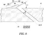
- Figure 8 shows a particle separator 184 as implemented within the invention as defined by the claims, and at least partially located upstream of the inlet of an effusion cooling aperture 69, 73.
- The, or each, particle separator 184 projects away from the first surface 41 and away from the combustion zone.
- The, or each, particle separator 184 overhangs the inlet of the effusion cooling aperture 69, 73.
- The, or each, particle separator 184 has a distal end 186 remote from the inlet of the effusion cooling aperture 69, 73 and a proximal end 188 adjacent to the inlet of the effusion cooling aperture 69, 73.
- The, or each, particle separator 184 has a first portion 190 adjacent the distal end 186, a second portion 192 adjacent the proximal end 188 and a third portion 194 between the first portion 190 and the second portion 192.
- the linear surface of the second portion 192 may be arranged at an angle of 30° to 80° to the first surface 41 of the 48A, 48B, 48C, 52A, 52B or 52C.
- the linear surface may be arranged at an angle of 40° to 75° to the first surface 41 of the 48A, 48B, 48C, 52A, 52B or 52C.
- each combustion chamber tile may comprise a monolithic structure consisting of consolidated powder material, e.g. consolidated powder metal.
- the main body, the peripheral wall, the attachment feature and the at least one particle separator of each combustion chamber tile may comprise a monolithic structure consisting of consolidated powder material, e.g. consolidate powder metal.
- The, or each, combustion chamber tile may be manufactured by an additive manufacturing technique using a powder material, the additive manufacturing technique comprising directing an energy beam on the powder material to consolidate the powder material to form each of the main body, the peripheral wall, the effusion cooling aperture and the particle separator by the additive manufacturing technique.
- the method may comprise directing a laser beam or an electron beam on the powder material.
- the method may comprise powder bed laser deposition.
- the main body of the combustion chamber tile may have pedestals, pins or fins, which project from the first surface of the combustion chamber tile, the additive manufacturing technique comprising directing an energy beam on the powder material to consolidate the powder material to form the pedestals, pins or fins.
- the powder material may be a metal powder.
- the metal powder may be a nickel base superalloy, a cobalt base superalloy or an iron base superalloy.
- the main body and the peripheral wall of each combustion chamber tile may comprise a monolithic structure consisting of a cast material, e.g. a cast metal.
- the main body, the peripheral wall, the attachment feature and the at least one particle separator of each combustion chamber tile may comprise a monolithic structure consisting of a cast material, e.g. cast metal.
- the main body of the combustion chamber tile may have pedestals, pins or fins, which project from the first surface of the combustion chamber tile.
- FIG. 9 Further combustion equipment 115 according to the present disclosure, as shown more clearly in Figures 9 and 10 , comprises an annular combustion chamber arrangement and comprises a radially inner annular wall structure 140, a radially outer annular wall structure 142 and an upstream end wall structure 144.
- the radially outer annular wall structure 142 comprises a plurality of combustion chamber segments 149 arranged circumferentially side by side to form the combustion chamber 115.
- Each combustion chamber segment 149 extends the full axial length of the combustion chamber 115.
- the combustion chamber segments 149 are removably secured together to form the combustion chamber 115.
- Each combustion chamber segment 149 comprises an outer wall 150 and an inner wall 152 spaced from the outer wall 150 and each combustion chamber segment 149 has a peripheral wall 182B extending around the edges of the combustion chamber segment 149 between the outer wall 150 and the inner wall 152 to space the inner wall 152 from the outer wall 150 and to define at least one chamber.
- the inner wall 152 of each combustion chamber segment 149 has a first surface 141 facing the outer wall 150 of the respective combustion chamber segment 149 and a second surface 143 facing away from the outer wall 150 of the combustion chamber segment 149 and towards a combustion zone.
- the radially inner annular wall structure 140 comprises a plurality of combustion chamber segments 145 arranged circumferentially side by side to form the combustion chamber 115.
- Each combustion chamber segment 145 extends the full axial length of the combustion chamber 115.
- the combustion chamber segments 145 are removably secured together to form the combustion chamber 115.
- Each combustion chamber segment 145 comprises an outer wall 146 and an inner wall 148 spaced from the outer wall 146 and each combustion chamber segment 145 has a peripheral wall 182A extending around the edges of the combustion chamber segment 145 between the outer wall 146 and the inner wall 148 to space the inner wall 148 from the outer wall 146 and to define at least one chamber.
- the inner wall 148 of each combustion chamber segment 145 has a first surface 141 facing the outer wall 146 of the respective combustion chamber segment 145 and a second surface 141 facing away from the outer wall 146 of the combustion chamber segment 145 and towards a combustion zone.
- the upstream ends of the combustion chamber segments 145 of the radially inner annular wall structure 140 are secured to the upstream end wall structure 244 and the upstream ends of the combustion chamber segments of the radially outer annular wall structure 142 are secured to the upstream end wall structure 244.
- the upstream end wall structure 144 has a plurality of circumferentially spaced apertures 154 and each aperture 154 has a respective one of a plurality of fuel injectors 156 located therein.
- the fuel injectors 156 are arranged to supply fuel into the annular combustion chamber 115 during operation of the gas turbine engine 10.
- each combustion chamber segment 145 has a plurality of effusion cooling apertures 173 extending there-through to provide a film of coolant onto the inner surface 143 of the inner wall 148 of the combustion chamber segments 145.
- the inner wall 152 of each combustion chamber segment 149 has a plurality of effusion cooling apertures 169 extending there-through to provide a film of coolant onto the inner surface 143 of the inner wall 152 of the combustion chamber segments 149.
- the combustion chamber segment is manufactured by an additive manufacturing technique using a powder material, the additive manufacturing technique comprising directing an energy beam on the powder material to consolidate the powder material to form each of the inner wall, the outer wall, the peripheral wall, the effusion cooling aperture and the particle separator by the additive manufacturing technique.
- the method may comprise directing a laser beam or an electron beam on the powder material.
- the method may comprise powder bed laser deposition.
- the combustion chamber segment may have pedestals, pins or fins, which project from the first surface of the inner wall of the combustion chamber segment, the additive manufacturing technique comprising directing an energy beam on the powder material to consolidate the powder material to form the pedestals, pins or fins.
- the powder material may be a metal powder.
- the metal powder may be a nickel base superalloy, a cobalt base superalloy or an iron base superalloy.
- the inner wall 148 has at least one particle separator positioned upstream of an effusion cooling aperture 173 and/or the inner wall 150 has at least one particle separator positioned upstream of an effusion cooling aperture 169.
- the inner wall 146 may have a plurality of particle separators, each particle separator is positioned upstream of one of the effusion cooling apertures 173 and/or the inner wall 152 has a plurality of particle separators, each particle separator is positioned upstream of one of the effusion cooling apertures 169.
- the particle separators according to the invention as defined by the claims are as shown and described with reference to Figure 8 .
- FIG. 11 comprises an annular combustion chamber arrangement and comprises a radially inner annular wall structure 240, a radially outer annular wall structure 242 and an upstream end wall structure 244.
- the radially inner annular wall structure 240 simply comprises a first annular wall 246.
- the radially outer annular wall structure 242 simply comprises a second annular wall 250.
- the upstream end of the first annular wall 246 is secured to the upstream end wall structure 244 and the upstream end of the second annular wall 250 is secured to the upstream end wall structure 244.
- the upstream end wall structure 244 has a plurality of circumferentially spaced apertures 254 and each aperture 254 has a respective one of a plurality of fuel injectors 256 located therein.
- the fuel injectors 256 are arranged to supply fuel into the annular combustion chamber 215 during operation of the gas turbine engine 10.
- the combustion chamber arrangement also comprises a plurality of dilution ports in the radially inner annular wall structure 240 and a plurality of dilution ports in the radially outer annular wall structure 242.
- the dilution ports in the radially inner annular wall structure 240 comprise a plurality of apertures 259 in the first annular wall 246 and the dilution ports in the radially outer annular wall structure 242 comprise a plurality of apertures 259 in the second annular wall 250.
- the first annular wall 246 has a first surface 241A facing away from the combustion zone and a second surface 243A facing the combustion zone.
- the first annular wall 246 has a plurality of effusion cooling apertures 273 extending there-through from the first surface 241A to the second surface 243A to provide a film of coolant onto the inner surface of the first annular wall 246.
- the effusion cooling aperture 273 have an inlet in the first surface 241A and an outlet in the second surface 243A.
- the second annular wall 250 has a first surface 241B facing away from the combustion zone and a second surface 243B facing the combustion zone.
- the second annular wall 250 has a plurality of effusion cooling apertures 269 extending there-through from the first surface 241B to the second surface 243B to provide a film of coolant onto the inner surface 243B of the second annular wall 250.
- the effusion cooling aperture 269 have an inlet in the first surface 241B and an outlet in the second surface 243B.
- the first surface 241A of the first annular wall 246 has at least one particle separator positioned upstream of an effusion cooling aperture 273 and/or the first surface 241B of the second annular wall 250 has at least one particle separator positioned upstream of an effusion cooling aperture 269.
- the first surface 241A of the first annular wall 246 may have a plurality of particle separators, each particle separator is positioned upstream of one of the effusion cooling apertures 273 and/or the first surface 241B of the second annular wall 250 may have a plurality of particle separators, each particle separator is positioned upstream of one of the effusion cooling apertures 269.
- the particle separators according to the invention as defined by the claims are described on Figure 8 .
- Figure 12 shows an arrangement in which the wall have a first plurality of effusion cooling apertures 69 and a second plurality of effusion cooling apertures 69A.
- the first surface 41 of the wall has a particle separator 84 located at least partially upstream of the inlet of each one of the first plurality of effusion cooling apertures 69.
- the second plurality of effusion cooling apertures 69A are located downstream of the first plurality of effusion cooling apertures 69 and the second plurality of effusion cooling apertures 69A have a greater cross-sectional area than the first plurality of effusion cooling apertures 69. In this arrangement any particles of sand, dust, grit, volcanic ash etc.
- the second plurality of effusion cooling apertures 69A may be interspersed within the first plurality of effusion cooling apertures 69. In this arrangement any particles of sand, dust, grit, volcanic ash etc. which may block the first plurality of effusion cooling apertures 69 is allowed to flow through the second plurality of apertures 69A to avoid accumulation of particles sand, dust, grit, volcanic ash etc. in the chamber between the tiles 48A, 48B, 48C, 52A, 52B, 52C and the first and/or third annular walls 46, 50.
- the inlet of the effusion cooling aperture 69, 73 in the first surface may be circular, elliptical, race-track or other suitable shape.
- the effusion cooling aperture 69, 73 may have a circular cross-section or a rectangular cross-section.
- the outlets of the effusion cooling apertures 69, 73 may be circular, elliptical, race-track, fan shaped or parallelogram shaped.
Landscapes
- Engineering & Computer Science (AREA)
- Chemical & Material Sciences (AREA)
- Combustion & Propulsion (AREA)
- Mechanical Engineering (AREA)
- General Engineering & Computer Science (AREA)
- Turbine Rotor Nozzle Sealing (AREA)
Description
- The present disclosure relates to a combustion chamber, a combustion chamber tile and a combustion chamber segment and in particular to a gas turbine engine combustion chamber, a gas turbine engine combustion chamber tile and a gas turbine engine combustion chamber segment.
- One known type of combustion chamber comprises one or more walls each of which comprises a double, or dual, wall structure. A dual wall structure comprises an annular outer wall and an annular inner wall spaced radially from the annular outer wall to define one or more chambers. The annular outer wall has a plurality of impingement cooling apertures to supply coolant into the chamber, or chambers, and the annular inner wall has a plurality of effusion cooling apertures to supply coolant from the chamber, or chambers, over an inner surface of the annular inner wall to provide a film of coolant on the inner surface of the annular inner wall. The film of coolant protects the inner surface of the annular inner wall.
- The annular inner wall generally comprises a plurality of rows of tiles arranged side by side between the upstream end of the combustion chamber and the downstream end of the combustion chamber and each row of tiles comprises a plurality of tiles arranged circumferentially side by side around the combustion chamber. Each tile comprises a main body having a first surface facing the annular outer wall and a second surface facing away from the annular outer wall and towards a combustion zone, each tile has a peripheral wall which extends around the edges of the tile and projects from the first surface towards the annular outer wall to space the tile from the annular outer wall to form at least one chamber. Each tile is secured to the annular outer wall by one or more attachment features. For example each tile is secured to the annular outer wall by one or more threaded studs which pass through respective apertures in the annular outer wall and a nut is provided on each threaded stud to secure the tile on the annular outer wall. Each tile has a plurality of effusion cooling apertures to supply coolant from the at least one chamber over an inner surface, the second surface, of the tile to provide a film of coolant on the inner surface, the second surface, of the tile. The film of coolant protects the inner surface of the tile.
- Alternatively, the annular wall comprises a plurality of combustion chamber segments arranged circumferentially side by side around the combustion chamber and each combustion chamber segment extends the full axial length of the combustion chamber. Each combustion chamber segment comprises an outer wall and an inner wall spaced from the outer wall, each combustion chamber segment has a peripheral wall which extends around the edges of the combustion chamber segment between the outer wall and the inner wall to space the inner wall from the outer wall and to define at least one chamber. Each combustion chamber segment has a plurality of effusion cooling apertures to supply coolant from the at least one chamber over an inner surface of the combustion chamber segment to provide a film of coolant on the inner surface of the combustion chamber segment. The film of coolant protects the inner surface of the combustion chamber segment.
- Another known type of combustion chamber comprises one or more walls each of which comprises a single wall structure. A single wall structure simply comprises an annular wall. The annular wall has a plurality of effusion cooling apertures to supply coolant from an outer surface through the annular wall and over an inner surface of the annular wall to provide a film of coolant on the inner surface of the annular wall. The film of coolant protects the inner surface of the annular wall.
- Generally the smaller the diameter, or cross-sectional area, of the effusion cooling aperture the better is the cooling performance of the effusion cooling aperture. However, an effusion cooling aperture with a very small diameter, or cross-sectional area, is more prone to blockage by sand, dust, grit, volcanic ash, etc. that is ingested into the gas turbine engine. The particles of sand, dust, grit, volcanic ash etc. may become lodged in the inlet of an effusion cooling aperture and block, or at least partially block, the effusion cooling aperture. Furthermore, some methods of manufacturing the effusion cooling apertures may reduce the minimum cross-sectional area of the effusion cooling aperture and further increase the propensity for blockage of the effusion cooling aperture. In particular effusion cooling apertures manufactured by additive manufacturing, or additive layer manufacturing, tend to produce effusion cooling apertures tend to produce circular cross-sectional effusion cooling apertures which are not circular.
- A combustion chamber according to the preamble of claim 1 is described by
WO2015/050592 . - Accordingly the present disclosure seeks to provide a combustion chamber which reduces, or overcomes, the above mentioned problem.
- According to a first aspect there is provided a combustion chamber comprising a wall at least partially defining a combustion zone, the wall having an upstream end and a downstream end, the wall having a first surface facing away from the combustion zone and a second surface facing the combustion zone, the wall having at least one effusion cooling aperture extending there-through from the first surface to the second surface, the effusion cooling aperture having an inlet in the first surface and an outlet in the second surface, the first surface having a particle separator at least partially located upstream of the inlet of the effusion cooling aperture, the particle separator projecting away from the first surface and away from the combustion zone, the particle separator having a distal end remote from the inlet of the effusion cooling aperture and a proximal end adjacent to the inlet of the effusion cooling aperture, the particle separator having a maximum height above the first surface at a location spaced from the proximal end, the particle separator increasing in height in a direction from the distal end towards the proximal end to the maximum height, wherein the particle separator overhangs the inlet of the effusion cooling aperture. The particle separator may be triangular in cross-section.
- The particle separator may have a first portion adjacent the distal end, a second portion adjacent the proximal end and a third portion between the first portion and the second portion. The third portion may increase in height at a constant rate between the first portion and the maximum height. The maximum height may be at the junction between the third portion and the second portion. The first portion may have a curved surface from the first surface of the wall to the third portion, the third portion having a linear surface. The second portion may have a linear surface. The second portion may comprise a curved surface. The second portion may comprise two curved surfaces. The second portion may comprise a first curved surface, a second curved surface and a linear surface between the first curved surface and the second curved surface. The first curved surface, the linear surface and the curved second surface being arranged in series between the junction with the third portion and the first surface of the wall. The linear surface may be arranged perpendicularly to the first surface of the wall. The maximum height of the particle separator may be equal to or greater than the diameter of the effusion cooling aperture.
- The first curved surface may be an arc of a circle. The arc of the circle may have a radius of one tenth of the diameter of the effusion cooling aperture. The arc of the circle may have a radius of 0.05mm. The second curved surface may be an arc of a circle. The arc of the circle may have a radius of three tenths to twelve tenths of the diameter of the effusion cooling aperture. The arc of the circle may have a radius of 0.15mm to 0.6mm. The curved surface of the first portion may be an arc of a circle. The arc of the circle may have a radius of four to twelve times the diameter of the effusion cooling aperture. The arc of the circle may have a radius of 2mm to 6mm.
- The effusion cooling aperture may have a diameter of 0.3 to 1.0mm. The effusion cooling aperture may have a diameter of 0.5mm. The effusion cooling aperture may be arranged perpendicularly to the first surface. The effusion cooling aperture may be arranged at an angle of 20° to 50° to the first surface.
- The particle separator may have a rectangular base. The particle separator may have a lateral dimension greater than the diameter of the effusion cooling aperture. The lateral dimension of the particle separator may be up to three times the diameter of the effusion cooling aperture. The particle separator may be arranged such that the middle of the particle separator is aligned with the centre of the effusion cooling aperture. The particle separator may be arranged such that the middle of the particle separator is aligned with an edge of the effusion cooling aperture. The particle separator may be wedge shaped.
- The proximal end of the particle separator may curve around the effusion cooling aperture. The third portion may be arranged at an angle of 25° to 50° to the first surface. The third portion may be arranged at an angle of 30° to the first surface. The particle separator may have a part annular base. The first portion may have a curved surface from the first surface of the wall to the third portion, the third portion having a frusto-conical surface.
- The inlet of the effusion cooling aperture in the first surface may be circular, elliptical, race-track or other suitable shape. The effusion cooling aperture may have a circular cross-section or a rectangular cross-section.
- The particle separator overhangs the inlet of the effusion cooling aperture. The linear surface may be arranged at an angle of 30° to 80° to the first surface of the wall. The linear surface may be arranged at an angle of 40° to 75° to the first surface of the wall.
- The wall may have a plurality of effusion cooling apertures. The first surface of the wall may have a plurality of particle separators, each particle separator is located at least partially upstream of the inlet of a respective one of a plurality of effusion cooling apertures. The wall may have a first plurality of effusion cooling apertures, the first surface of the wall having a plurality of particle separators, each particle separator is located at least partially upstream of the inlet of a respective one of the first plurality of effusion cooling apertures, a second plurality of effusion cooling apertures, and the second plurality of effusion cooling apertures having a greater cross-sectional area than the first plurality of effusion cooling apertures. The second plurality of effusion cooling apertures may be located downstream of the first plurality of effusion cooling apertures. The second plurality of effusion cooling apertures may be interspersed, distributed at intervals, within the first plurality of effusion cooling apertures.
- The effusion cooling apertures may be arranged in a plurality of rows, each row comprising a plurality of effusion cooling apertures. The effusion cooling apertures in adjacent rows may be staggered with respect to each other.
- The wall may be an annular wall defining at least partially defining the combustion zone. The annular wall may be a radially inner annular wall of an annular combustion chamber or a radially outer annular wall of an annular combustion chamber.
- The wall may be a combustion chamber tile defining at least partially defining the combustion zone, the combustion chamber tile being removably secured to an annular wall. The combustion chamber tile may be removably secured to a radially inner annular wall of an annular combustion chamber or removably secured to a radially outer annular wall of an annular combustion chamber. There may be a plurality of combustion chamber tiles. Each combustion chamber tile may be removably secured to the annular wall. Each combustion chamber tile may comprise a main body having a first surface facing the annular wall and a second surface facing away from the annular wall and towards the combustion zone, each combustion chamber tile having a peripheral wall extending around the edges of the combustion chamber tile and projecting from the first surface towards the annular wall to space the tile from the annular wall. The main body and the peripheral wall of each combustion chamber tile may comprise a monolithic structure consisting of consolidated powder material.
- The wall may be a combustion chamber segment defining at least partially the combustion zone, the combustion chamber segment being arranged circumferentially side by side with other combustion chamber segments to form the combustion chamber. The combustion chamber segment comprising an outer wall and an inner wall spaced from the outer wall, the combustion chamber segment having a peripheral wall extending around the edges of the combustion chamber segment between the outer wall and the inner wall to space the inner wall from the outer wall and to define at least one chamber, the inner wall of the combustion chamber segment having a first surface facing the outer wall of the combustion chamber segment and a second surface facing away from the outer wall of the combustion chamber segment and towards a combustion zone, the combustion chamber segment having an effusion cooling aperture extending through the inner wall from the first surface to the second surface, the effusion cooling aperture having an inlet in the first surface and an outlet in the second surface, the effusion cooling aperture having a diameter, the first surface having a particle separator located upstream of the inlet of the effusion cooling aperture, the particle separator projecting from the first surface towards the outer wall but being spaced from the outer wall, the particle separator having a distal end remote from the effusion cooling aperture and a proximal end adjacent to the effusion cooling aperture, the particle separator having a maximum height upstream of the proximal end, the particle separator increasing in height in a direction from the distal end to towards the proximal end to the maximum height.
- According to a second aspect which is not part of the invention as defined by the claims, there is provided a combustion chamber comprising an annular wall and a plurality of combustion chamber tiles, each combustion chamber tile being removably secured to the annular wall, each combustion chamber tile comprising a main body having a first surface facing the annular wall and a second surface facing away from the annular wall and towards a combustion zone, each combustion chamber tile having a peripheral wall extending around the edges of the combustion chamber tile and projecting from the first surface towards the annular wall to space the combustion chamber tile from the annular wall, at least one of the combustion chamber tiles having an effusion cooling aperture extending through the main body from the first surface to the second surface, the effusion cooling aperture having an inlet in the first surface and an outlet in the second surface, the effusion cooling aperture having a diameter, the first surface having a particle separator located upstream of the inlet of the effusion cooling aperture, the particle separator projecting from the first surface towards the annular wall but being spaced from the annular wall, the particle separator having a distal end remote from the effusion cooling aperture and a proximal end adjacent to the effusion cooling aperture, the particle separator having a maximum height upstream of the proximal end, the particle separator increasing in height in a direction from the distal end to towards the proximal end to the maximum height.
- The first surface of at least one of the combustion chamber tiles may have a plurality of particle separators, each particle separator is located at least partially upstream of the inlet of a respective one of a plurality of effusion cooling apertures. The first surface of a plurality of the combustion chamber tiles may have a particle separator located at least partially upstream of the inlet of an effusion cooling apertures. The first surface of a plurality of combustion chamber tiles may have a plurality of particle separators, each particle separator is located at least partially upstream of the inlet of a respective one of a plurality of effusion cooling apertures. The first surface of each of the combustion chamber tiles may have a particle separator located at least partially upstream of the inlet of an effusion cooling apertures. The first surface of each of the combustion chamber tiles may have a plurality of particle separators, each particle separator is located at least partially upstream of the inlet of a respective one of a plurality of effusion cooling apertures.
- According to a third aspect which is not part of the invention as defined by the claims, there is provided a combustion chamber tile comprising a main body having a first surface and a second surface facing in the opposite direction to the first surface, the combustion chamber tile having a peripheral wall extending around the edges of the combustion chamber tile and projecting from the first surface, the combustion chamber tile having an effusion cooling aperture extending through the main body from the first surface to the second surface, the effusion cooling aperture having an inlet in the first surface and an outlet in the second surface, the effusion cooling aperture having a diameter, the first surface having a particle separator located upstream of the inlet of the effusion cooling aperture, the particle separator projecting from the first surface, the particle separator having a distal end remote from the effusion cooling aperture and a proximal end adjacent to the effusion cooling aperture, the particle separator having a maximum height upstream of the proximal end, the particle separator increasing in height in a direction from the distal end to towards the proximal end to the maximum height.
- The combustion chamber tile may be manufactured by an additive manufacturing technique using a powder material, the additive manufacturing technique comprising directing an energy beam on the powder material to consolidate the powder material to form each of the main body, the peripheral wall, the effusion cooling aperture and the particle separator. The method may comprise directing a laser beam or an electron beam on the powder material. The method may comprise powder bed laser deposition. The combustion chamber tile may comprise at least one attachment feature projecting from the first surface, the additive manufacturing technique comprising directing an energy beam on the powder material to consolidate the powder material to form each of the main body, the peripheral wall, the effusion cooling aperture, the particle separator and the at least on attachment feature by the additive manufacturing technique. The at least one attachment feature may be a stud. The main body of the combustion chamber tile may have pedestals, pins or fins, which project from the first surface of the combustion chamber tile, the additive manufacturing technique comprising directing an energy beam on the powder material to consolidate the powder material to form the pedestals, pins or fins. The powder material may be a metal powder. The metal powder may be a nickel base superalloy, a cobalt base superalloy or an iron base superalloy.
- According to a fourth aspect which is not part of the invention as defined by the claims, there is provided a combustion chamber comprising a plurality of combustion chamber segments arranged circumferentially side by side to form the combustion chamber, each combustion chamber segment extending the full axial length of the combustion chamber, the combustion chamber segments being removably secured together to form the combustion chamber, each combustion chamber segment comprising an outer wall and an inner wall spaced from the outer wall, each combustion chamber segment having a peripheral wall extending around the edges of the combustion chamber segment between the outer wall and the inner wall to space the inner wall from the outer wall and to define at least one chamber, the inner wall of each combustion chamber segment having a first surface facing the outer wall of the respective combustion chamber segment and a second surface facing away from the outer wall of the combustion chamber segment and towards a combustion zone, at least one of combustion chamber segments having an effusion cooling aperture extending through the inner wall from the first surface to the second surface, the effusion cooling aperture having an inlet in the first surface and an outlet in the second surface, the effusion cooling aperture having a diameter, the first surface having a particle separator located upstream of the inlet of the effusion cooling aperture, the particle separator projecting from the first surface towards the outer wall but being spaced from the outer wall, the particle separator having a distal end remote from the effusion cooling aperture and a proximal end adjacent to the effusion cooling aperture, the particle separator having a maximum height upstream of the proximal end, the particle separator increasing in height in a direction from the distal end to towards the proximal end to the maximum height.
- The first surface of at least one of the combustion chamber segments may have a plurality of particle separators, each particle separator is located at least partially upstream of the inlet of a respective one of a plurality of effusion cooling apertures. The first surface of a plurality of the combustion chamber segments may have a particle separator located at least partially upstream of the inlet of an effusion cooling apertures. The first surface of a plurality of combustion chamber segments may have a plurality of particle separators, each particle separator is located at least partially upstream of the inlet of a respective one of a plurality of effusion cooling apertures. The first surface of each of the combustion chamber segments may have a particle separator located at least partially upstream of the inlet of an effusion cooling apertures. The first surface of each of the combustion chamber segments may have a plurality of particle separators, each particle separator is located at least partially upstream of the inlet of a respective one of a plurality of effusion cooling apertures.
- According to a fifth aspect which is not part of the invention as defined by the claims, there is provided a combustion chamber segment comprising an outer wall and an inner wall spaced from the outer wall, the combustion chamber segment having a peripheral wall extending around the edges of the combustion chamber segment between the outer wall and the inner wall to space the inner wall from the outer wall and to define at least one chamber, the inner wall of the combustion chamber segment having a first surface facing the outer wall of the combustion chamber segment and a second surface facing away from the outer wall of the combustion chamber segment and towards a combustion zone, the combustion chamber segment having an effusion cooling aperture extending through the inner wall from the first surface to the second surface, the effusion cooling aperture having an inlet in the first surface and an outlet in the second surface, the effusion cooling aperture having a diameter, the first surface having a particle separator located upstream of the inlet of the effusion cooling aperture, the particle separator projecting from the first surface towards the outer wall but being spaced from the outer wall, the particle separator having a distal end remote from the effusion cooling aperture and a proximal end adjacent to the effusion cooling aperture, the particle separator having a maximum height upstream of the proximal end, the particle separator increasing in height in a direction from the distal end to towards the proximal end to the maximum height.
- The combustion chamber segment may be manufactured by an additive manufacturing technique using a powder material, the additive manufacturing technique comprising directing an energy beam on the powder material to consolidate the powder material to form each of the inner wall, the outer wall, the peripheral wall, the effusion cooling aperture and the particle separator. The method may comprise directing a laser beam or an electron beam on the powder material. The method may comprise powder bed laser deposition. The combustion chamber segment may have pedestals, pins or fins, which project from the first surface of the inner wall of the combustion chamber segment, the additive manufacturing technique comprising directing an energy beam on the powder material to consolidate the powder material to form the pedestals, pins or fins. The powder material may be a metal powder. The metal powder may be a nickel base superalloy, a cobalt base superalloy or an iron base superalloy.
- As noted elsewhere herein, the present disclosure may relate to a gas turbine engine. Such a gas turbine engine may comprise an engine core comprising a turbine, a combustor, a compressor, and a core shaft connecting the turbine to the compressor. Such a gas turbine engine may comprise a fan (having fan blades) located upstream of the engine core.
- The gas turbine engine as described and/or claimed herein may have any suitable general architecture. For example, the gas turbine engine may have any desired number of shafts that connect turbines and compressors, for example one, two or three shafts. Purely by way of example, the turbine connected to the core shaft may be a first turbine, the compressor connected to the core shaft may be a first compressor, and the core shaft may be a first core shaft. The engine core may further comprise a second turbine, a second compressor, and a second core shaft connecting the second turbine to the second compressor. The second turbine, second compressor, and second core shaft may be arranged to rotate at a higher rotational speed than the first core shaft.
- In such an arrangement, the second compressor may be positioned axially downstream of the first compressor. The second compressor may be arranged to receive (for example directly receive, for example via a generally annular duct) flow from the first compressor.
- In any gas turbine engine as described and/or claimed herein, a combustor may be provided axially downstream of the fan and compressor(s). For example, the combustor may be directly downstream of (for example at the exit of) the second compressor, where a second compressor is provided. By way of further example, the flow at the exit to the combustor may be provided to the inlet of the second turbine, where a second turbine is provided. The combustor may be provided upstream of the turbine(s).
- The or each compressor (for example the first compressor and second compressor as described above) may comprise any number of stages, for example multiple stages. Each stage may comprise a row of rotor blades and a row of stator vanes, which may be variable stator vanes (in that their angle of incidence may be variable). The row of rotor blades and the row of stator vanes may be axially offset from each other. The or each turbine (for example the first turbine and second turbine as described above) may comprise any number of stages, for example multiple stages. Each stage may comprise a row of rotor blades and a row of stator vanes. The row of rotor blades and the row of stator vanes may be axially offset from each other. The skilled person will appreciate that except where mutually exclusive, a feature or parameter described in relation to any one of the above aspects may be applied to any other aspect. Furthermore, except where mutually exclusive, any feature or parameter described herein may be applied to any aspect and/or combined with any other feature or parameter described herein.
- Embodiments will now be described by way of example only, with reference to the Figures, in which:
-
Figure 1 is a sectional side view of a gas turbine engine. -
Figure 2 is an enlarged cross-sectional view of a combustion chamber arrangement presenting a configuration which is not part of the invention as defined by the claims. -
Figure 3 is a further enlarged perspective view of a combustion chamber tile of the combustion chamber arrangement shown inFigure 2 . -
Figure 4 is a further enlarged cross-sectional view of a combustion chamber tile of the combustion chamber arrangement shown inFigure 2 . -
Figure 5 is a plan view of the combustion chamber tile in the direction of arrow A inFigure 4 . -
Figure 6 is an alternative plan view of the combustion chamber tile in the direction of arrow A inFigure 4 . -
Figure 7 is another alternative plan view of the combustion chamber tile in the direction of arrow A inFigure 4 . -
Figure 8 is an enlarged cross-sectional view of a combustion chamber - tile of the combustion chamber arrangement according to the invention as defined by the claims.
-
Figure 9 is an enlarged cross-sectional view of an alternative combustion chamber - arrangement presenting a configuration which is not part of the invention as defined by the claims.
-
Figure 10 is a further enlarged perspective view of a combustion chamber segment of the combustion chamber arrangement shown inFigure 9 . -
Figure 11 is an enlarged cross-sectional view of a further combustion chamber arrangement according to the present disclosure. -
Figure 12 is a further plan view of the combustion chamber tile in the direction of arrow A inFigure 4 . -
Figure 1 illustrates agas turbine engine 10 having a principalrotational axis 9. Theengine 10 comprises anair intake 12 and a propulsive fan 23 that generates two airflows: a core airflow A and a bypass airflow B. Thegas turbine engine 10 comprises a core 11 that receives the core airflow A. Theengine core 11 comprises, in axial flow series, alow pressure compressor 14, a high-pressure compressor 31,combustion equipment 16, a high-pressure turbine 17, alow pressure turbine 19 and acore exhaust nozzle 20. Anacelle 21 surrounds thegas turbine engine 10 and defines abypass duct 22 and abypass exhaust nozzle 18. The bypass airflow B flows through thebypass duct 22. The fan 23 is attached to and driven by thelow pressure turbine 19 via ashaft 26 and anepicyclic gearbox 30. - In use, the core airflow A is accelerated and compressed by the
low pressure compressor 14 and directed into thehigh pressure compressor 31 where further compression takes place. The compressed air exhausted from thehigh pressure compressor 31 is directed into thecombustion equipment 16 where it is mixed with fuel and the mixture is combusted. The resultant hot combustion products then expand through, and thereby drive, the high pressure andlow pressure turbines nozzle 20 to provide some propulsive thrust. Thehigh pressure turbine 17 drives thehigh pressure compressor 31 by a suitable interconnectingshaft 27. The fan 23 generally provides the majority of the propulsive thrust. Theepicyclic gearbox 30 is a reduction gearbox. - The geometry of the
gas turbine engine 10, and components thereof, is defined by a conventional axis system, comprising an axial direction (which is aligned with the rotational axis 9), a radial direction (in the bottom-to-top direction inFigure 1 ), and a circumferential direction (perpendicular to the page in theFigure 1 view). The axial, radial and circumferential directions are mutually perpendicular. -
Combustion equipment 16 according to the present disclosure, as shown more clearly inFigures 2, 3 ,4 and 5 , comprises anannular combustion chamber 15 arrangement and comprises a radially innerannular wall structure 40, a radially outerannular wall structure 42 and an upstreamend wall structure 44. The radially innerannular wall structure 40 comprises a firstannular wall 46 and a secondannular wall 48. The radially outerannular wall structure 42 comprises a thirdannular wall 50 and a fourthannular wall 52. The secondannular wall 48 is spaced radially from and is arranged radially around the firstannular wall 46 and the firstannular wall 46 supports the secondannular wall 48. The fourthannular wall 52 is spaced radially from and is arranged radially within the thirdannular wall 50 and the thirdannular wall 50 supports the fourthannular wall 52. The upstream end of the firstannular wall 46 is secured to the upstreamend wall structure 44 and the upstream end of the thirdannular wall 50 is secured to the upstreamend wall structure 44. The upstreamend wall structure 44 has a plurality of circumferentially spacedapertures 54 and eachaperture 54 has a respective one of a plurality offuel injectors 56 located therein. Thefuel injectors 56 are arranged to supply fuel into theannular combustion chamber 15 during operation of thegas turbine engine 10. - The first
annular wall 46 has a plurality of mountingapertures 58 extending there-though and the secondannular wall 48 has a plurality of attachment features 60 extending radially there-from. Each attachment feature 60 on the secondannular wall 48 extends radially through a corresponding mountingaperture 58 in the firstannular wall 46. A cooperatingfastener 62 locates on each of the attachment features 60 extending through the mountingapertures 58 in the firstannular wall 46. Awasher 64 is positioned between eachattachment feature 60 on the secondannular wall 48 and the cooperatingfastener 62. Eachwasher 64 has afirst surface 66 abutting an outer surface of the firstannular wall 46 and asecond surface 68 abutting a surface of the cooperatingfastener 62. The secondannular wall 48 comprises a plurality oftiles tiles annular wall 46. The axially extending edges ofadjacent tiles adjacent tiles - Similarly, the third
annular wall 50 has a plurality of mountingapertures 70 extending there-though and the fourthannular wall 52 has a plurality of attachment features 72 extending radially there-from. Each attachment feature 72 on the fourthannular wall 52 extends radially through a corresponding mountingaperture 70 in the thirdannular wall 50. A cooperatingfastener 74 locates on each of the attachment features 72 extending through the mountingapertures 70 in the thirdannular wall 50. Awasher 76 is positioned between eachattachment feature 72 on the fourthannular wall 52 and the cooperatingfastener 74. Eachwasher 76 has afirst surface 78 abutting an outer surface of the thirdannular wall 50 and asecond surface 80 abutting a surface of the cooperatingfastener 74. The fourthannular wall 52 comprises a plurality oftiles tiles annular wall 52. The axially extending edges ofadjacent tiles adjacent tiles - The attachment features 60 and 72 on the second and fourth
annular walls tiles 52A tiles tiles 52A fasteners - The first and third
annular walls annular combustion chamber 15 and the second and fourthannular walls annular combustion chamber 15. The second and fourthannular walls annular wall 48 comprises at least one row of circumferentially arranged tiles and in this example there are threerows tiles 48A form an axially upstream row of circumferentially arranged tiles, thetiles 48B form an axially intermediate row of circumferentially arranged tiles and thetiles 48C form an axially downstream row of circumferentially arranged tiles. Each of the tiles of the secondannular wall 48 is a wall at least partially defining the combustion zone. Similarly, the fourthannular wall 52 comprises at least one row of circumferentially arranged tiles and in this example there are threerows tiles 52A form an axially upstream row of circumferentially arranged tiles, thetiles 52B form an axially intermediate row of circumferentially arranged tiles and thetiles 52C form an axially downstream row of circumferentially arranged tiles. Each of the tiles of the fourthannular wall 52 is a wall at least partially defining the combustion zone. - The combustion chamber arrangement also comprises a plurality of dilution ports in the radially inner
annular wall structure 40 and a plurality of dilution ports in the radially outerannular wall structure 42. The dilution ports in the radially outerannular wall structure 42 comprises a plurality of alignedapertures outer wall 50 and thetiles 52B of the annularinner wall 52. The dilution ports in the radially innerannular wall structure 40 comprise a plurality of aligned apertures in the annularouter wall 46 and thetiles 48B of the annularinner wall 48. The dilution ports supply dilution air into the combustion chamber to control emissions. - Each of the
combustion chamber tiles main body 45 which has afirst surface 41 and asecond surface 43, as shown inFigure 3 . Thefirst surface 41 of eachcombustion chamber tile annular wall second surface 43 of eachcombustion chamber tile annular wall combustion chamber 15. - The annular
outer wall 50 has a plurality ofimpingement cooling apertures 67 extending there-through to direct coolant, e.g. air, onto the outer surface, e.g. the first surface, 41 of thetiles tiles effusion cooling apertures 69 extending there-through to provide a film of coolant onto the inner surfaces of thetiles impingement cooling apertures 67 are generally arranged perpendicularly to the surfaces of the annular outer all 50 and the outer surfaces of thetiles effusion cooling apertures 69 are generally arranged at an acute angle, for example 30°, to the inner surfaces of thetiles effusion cooling apertures 69 may be arranged perpendicularly to the inner surfaces of thetiles effusion cooling apertures 69 may be arranged at an acute angle, for example 30°, to the inner surfaces of thetiles impingement cooling apertures 67 are generally arranged in rows in which theimpingement cooling apertures 67 are circumferentially spaced and theimpingement cooling apertures 67 in axially adjacent rows are circumferentially staggered. - The annular
outer wall 46 has a plurality ofimpingement cooling apertures 71 extending there-through to direct coolant, e.g. air, onto the outer surface, e.g. the first surface, 41 of thetiles tiles effusion cooling apertures 73 extending there-through to provide a film of coolant onto the inner surfaces of thetiles impingement cooling apertures 71 are generally arranged perpendicularly to the surfaces of the annular outer all 46 and the outer surfaces of thetiles effusion cooling apertures 73 are generally arranged at an acute angle, for example 30°, to the inner surfaces of thetiles effusion cooling apertures 73 may be arranged perpendicularly to the inner surfaces of thetiles effusion cooling apertures 73 may be arranged at an acute angle, for example 30°, to the inner surfaces of thetiles impingement cooling apertures 71 are generally arranged in rows in which theimpingement cooling apertures 71 are circumferentially spaced and theimpingement cooling apertures 71 in axially adjacent rows are circumferentially staggered. - The
effusion cooling apertures combustion chamber tiles first surface 41 to thesecond surface 43. Eacheffusion cooling aperture first surface 41 and anoutlet 43 in thesecond surface 43. Theeffusion cooling apertures effusion cooling apertures effusion cooling apertures effusion cooling apertures effusion cooling apertures second surface 43 of thecombustion chamber tiles effusion cooling apertures second surface 43 of thecombustion chamber tiles effusion cooling apertures second surface 43 of thecombustion chamber tiles - Each
combustion chamber tile Figure 3 , and comprises a peripheral wall, or rail, 82 which extends around the periphery of thetile first surface 41 of thetile annular wall 46 or thirdannular wall 50 respectively. The peripheral wall, or rail, 82 spaces thetile annular wall 46 or thirdannular wall 50 respectively and forms a chamber between thetile annular wall 46 or thirdannular wall 50 respectively. The peripheral wall, or rail, 82 comprises axially spaced circumferentially extendingwall portions wall portions wall portions tile first surface 41 of themain body 45. The attachment features 60, 72 project from thefirst surface 41 of themain body 45. - The
first surface 41 of at least one of thetiles particle separator 84 at least partially located upstream of the inlet of aneffusion cooling aperture Figures 4 and 5 . In this example thefirst surface 41 of each of thetiles particle separators 84, eachparticle separator 84 is located at least partially upstream of the inlet of a respective one of a plurality ofeffusion cooling apertures first surface 41 of at least one of thetiles particle separators 84, eachparticle separator 84 is located at least partially upstream of the inlet of a respective one of a plurality ofeffusion cooling apertures first surface 41 of a plurality of thetiles particle separator 84 located at least partially upstream of the inlet of aneffusion cooling apertures first surface 41 of a plurality of thetiles particle separators 84, eachparticle separator 84 is located at least partially upstream of the inlet of a respective one of a plurality ofeffusion cooling apertures first surface 41 of each of thetiles particle separator 84 located at least partially upstream of the inlet of aneffusion cooling apertures - The, or each,
particle separator 84 projects away from thefirst surface 41 and away from the combustion zone. The, or each,particle separator 84 has adistal end 86 remote from the inlet of theeffusion cooling aperture proximal end 88 adjacent to the inlet of theeffusion cooling aperture particle separator 84 has a maximum height H above thefirst surface 41 at a location spaced from theproximal end 88. The, or each,particle separator 84 increases in height in a direction from thedistal end 86 towards theproximal end 88 to the maximum height H. Theparticle separator 84 is generally triangular in cross-section. The, or each,particle separator 84 has afirst portion 90 adjacent thedistal end 86, asecond portion 92 adjacent theproximal end 88 and athird portion 94 between thefirst portion 90 and thesecond portion 92. Thethird portion 94 increases in height at a constant rate between thefirst portion 90 and the maximum height H. The maximum height H is at the junction between thethird portion 94 and thesecond portion 92. Thefirst portion 90 has a curved surface from thefirst surface 41 of thetile third portion 94. Eachparticle separator 84 is designed to produce a flow of coolant, air, and any particles of sand, dust, grit or volcanic ash etc. such that the coolant may turn and flow into the respective inlet of theeffusion cooling aperture effusion cooling aperture effusion cooling aperture particle separator 84 is designed to minimise separation of the coolant flow from the surface of theparticle separator 84 - The curved surface of the
first portion 90 of the, or each,particle separator 84 comprises an arc of a circle. The arc of the circle has a radius R1 of four to twelve times the diameter D of theeffusion cooling aperture second portion 92 comprises a first curved surface, a second curved surface and a linear surface between the first curved surface and the second curved surface. The first curved surface, the linear surface and the second curved surface are arranged in series between the junction with thethird portion 94 and thefirst surface 41 of thetile first surface 41. Alternatively, thesecond portion 92 of the, or each,particle separator 84 may simply comprise a linear surface between the junction with thethird portion 94 and thefirst surface 41 of thetile first surface 41 of thetile first surface 41 of thetile particle separator 84 overhangs theeffusion cooling aperture second portion 92 comprises an arc of a circle. The arc of the circle has a radius R2 of one tenth of the diameter D of theeffusion cooling aperture effusion cooling aperture proximal end 88 of theparticle separator 84 and the inlet of theeffusion cooling aperture particle separator 84. However, the smaller the radius R3 the greater is the change in thickness of thetile tile tile third portion 94 of the, or each,particle separator 84 comprises a linear surface. The maximum height H of theparticle separator 84 is equal to or greater than the diameter D of theeffusion cooling aperture effusion cooling aperture third portion 94 may be arranged at an angle of 25° to 50° to thefirst surface 41. - In one example the, or each,
effusion cooling aperture third portion 94 is arranged at an angle of 30° to thefirst surface 41. - The
particle separators 84 are placed upstream of the inlets of theeffusion cooling apertures effusion cooling apertures effusion cooling apertures particle separators 84 are tuned to generate streamlines of appropriate curvature to effectively separate particles above a certain size and density. This curvature would be tuned to ensure that only particles sufficiently small may pass through theeffusion cooling aperture particle separator 84 centrifuges particles in the size range 0.6 mm to 0.2 mm away from theeffusion cooling aperture effusion cooling apertures effusion cooling apertures - In
Figures 4 and 5 theparticle separator 84 has an arcuatedistal end 86 and an arcuateproximal end 88 curving around an upstream end of the inlet of theeffusion cooling aperture particle separator 84 may have a part annular base. Thefirst portion 90 of aparticle separator 84 with a part annular base has a curved surface from thefirst surface 41 of thetile third portion 94 and thethird portion 94 has a frusto-conical surface. Thesecond portion 92 of theparticle separator 84 with a part annular base has a part cylindrical linear surface. -
Figure 6 shows analternative particle separator 84 at least partially located upstream of the inlet of aneffusion cooling aperture particle separator 84 projects away from thefirst surface 41 and away from the combustion zone. The, or each,particle separator 84 has adistal end 86 remote from the inlet of theeffusion cooling aperture proximal end 88 adjacent to the inlet of theeffusion cooling aperture Figure 4 . Theparticle separator 84 shown inFigure 6 differs in that theparticle separator 84 has a substantially rectangular base. Theparticle separator 84 inFigure 6 is substantially wedge shaped. Thefirst portion 90 of aparticle separator 84 with a rectangular base has a curved surface from thefirst surface 41 of thetile third portion 94 and thethird portion 94 has a planar surface. Thesecond portion 92 of theparticle separator 84 with a part rectangular base has a planar linear surface. Theparticle separator 84 has a lateral dimension greater than the diameter D of theeffusion cooling aperture particle separator 84 may be up to three times the diameter D of theeffusion cooling aperture particle separator 84 may be arranged such that the middle of theparticle separator 84 is aligned with the centre of theeffusion cooling aperture particle separator 84 in this example is arranged such that the middle of theparticle separator 84 is aligned with an edge of theeffusion cooling aperture -
Figure 7 shows analternative particle separator 84 at least partially located upstream of the inlet of aneffusion cooling aperture particle separator 84 projects away from thefirst surface 41 and away from the combustion zone. The, or each,particle separator 84 has adistal end 86 remote from the inlet of theeffusion cooling aperture proximal end 88 adjacent to the inlet of theeffusion cooling aperture Figure 4 . Theeffusion cooling aperture particle separator 84 shown inFigure 7 differ in that theeffusion cooling aperture particle separator 84 is shaped to match the concave upstream end wall/surface. -
Figure 8 shows aparticle separator 184 as implemented within the invention as defined by the claims, and at least partially located upstream of the inlet of aneffusion cooling aperture particle separator 184 projects away from thefirst surface 41 and away from the combustion zone. The, or each,particle separator 184 overhangs the inlet of theeffusion cooling aperture particle separator 184 has adistal end 186 remote from the inlet of theeffusion cooling aperture proximal end 188 adjacent to the inlet of theeffusion cooling aperture particle separator 184 has afirst portion 190 adjacent thedistal end 186, asecond portion 192 adjacent theproximal end 188 and athird portion 194 between thefirst portion 190 and thesecond portion 192. The linear surface of thesecond portion 192 may be arranged at an angle of 30° to 80° to thefirst surface 41 of the 48A, 48B, 48C, 52A, 52B or 52C. The linear surface may be arranged at an angle of 40° to 75° to thefirst surface 41 of the 48A, 48B, 48C, 52A, 52B or 52C. - The main body and the peripheral wall of each combustion chamber tile may comprise a monolithic structure consisting of consolidated powder material, e.g. consolidated powder metal. The main body, the peripheral wall, the attachment feature and the at least one particle separator of each combustion chamber tile may comprise a monolithic structure consisting of consolidated powder material, e.g. consolidate powder metal. The, or each, combustion chamber tile may be manufactured by an additive manufacturing technique using a powder material, the additive manufacturing technique comprising directing an energy beam on the powder material to consolidate the powder material to form each of the main body, the peripheral wall, the effusion cooling aperture and the particle separator by the additive manufacturing technique. The method may comprise directing a laser beam or an electron beam on the powder material. The method may comprise powder bed laser deposition. The main body of the combustion chamber tile may have pedestals, pins or fins, which project from the first surface of the combustion chamber tile, the additive manufacturing technique comprising directing an energy beam on the powder material to consolidate the powder material to form the pedestals, pins or fins. The powder material may be a metal powder. The metal powder may be a nickel base superalloy, a cobalt base superalloy or an iron base superalloy. The main body and the peripheral wall of each combustion chamber tile may comprise a monolithic structure consisting of a cast material, e.g. a cast metal. The main body, the peripheral wall, the attachment feature and the at least one particle separator of each combustion chamber tile may comprise a monolithic structure consisting of a cast material, e.g. cast metal. The main body of the combustion chamber tile may have pedestals, pins or fins, which project from the first surface of the combustion chamber tile.
-
Further combustion equipment 115 according to the present disclosure, as shown more clearly inFigures 9 and10 , comprises an annular combustion chamber arrangement and comprises a radially innerannular wall structure 140, a radially outerannular wall structure 142 and an upstreamend wall structure 144. The radially outerannular wall structure 142 comprises a plurality ofcombustion chamber segments 149 arranged circumferentially side by side to form thecombustion chamber 115. Eachcombustion chamber segment 149 extends the full axial length of thecombustion chamber 115. Thecombustion chamber segments 149 are removably secured together to form thecombustion chamber 115. Eachcombustion chamber segment 149 comprises anouter wall 150 and aninner wall 152 spaced from theouter wall 150 and eachcombustion chamber segment 149 has aperipheral wall 182B extending around the edges of thecombustion chamber segment 149 between theouter wall 150 and theinner wall 152 to space theinner wall 152 from theouter wall 150 and to define at least one chamber. Theinner wall 152 of eachcombustion chamber segment 149 has afirst surface 141 facing theouter wall 150 of the respectivecombustion chamber segment 149 and asecond surface 143 facing away from theouter wall 150 of thecombustion chamber segment 149 and towards a combustion zone. The radially innerannular wall structure 140 comprises a plurality ofcombustion chamber segments 145 arranged circumferentially side by side to form thecombustion chamber 115. Eachcombustion chamber segment 145 extends the full axial length of thecombustion chamber 115. Thecombustion chamber segments 145 are removably secured together to form thecombustion chamber 115. Eachcombustion chamber segment 145 comprises anouter wall 146 and aninner wall 148 spaced from theouter wall 146 and eachcombustion chamber segment 145 has aperipheral wall 182A extending around the edges of thecombustion chamber segment 145 between theouter wall 146 and theinner wall 148 to space theinner wall 148 from theouter wall 146 and to define at least one chamber. Theinner wall 148 of eachcombustion chamber segment 145 has afirst surface 141 facing theouter wall 146 of the respectivecombustion chamber segment 145 and asecond surface 141 facing away from theouter wall 146 of thecombustion chamber segment 145 and towards a combustion zone. The upstream ends of thecombustion chamber segments 145 of the radially innerannular wall structure 140 are secured to the upstreamend wall structure 244 and the upstream ends of the combustion chamber segments of the radially outerannular wall structure 142 are secured to the upstreamend wall structure 244. The upstreamend wall structure 144 has a plurality of circumferentially spacedapertures 154 and eachaperture 154 has a respective one of a plurality offuel injectors 156 located therein. Thefuel injectors 156 are arranged to supply fuel into theannular combustion chamber 115 during operation of thegas turbine engine 10. - The
inner wall 148 of eachcombustion chamber segment 145 has a plurality ofeffusion cooling apertures 173 extending there-through to provide a film of coolant onto theinner surface 143 of theinner wall 148 of thecombustion chamber segments 145. Similarly, theinner wall 152 of eachcombustion chamber segment 149 has a plurality ofeffusion cooling apertures 169 extending there-through to provide a film of coolant onto theinner surface 143 of theinner wall 152 of thecombustion chamber segments 149. - The combustion chamber segment is manufactured by an additive manufacturing technique using a powder material, the additive manufacturing technique comprising directing an energy beam on the powder material to consolidate the powder material to form each of the inner wall, the outer wall, the peripheral wall, the effusion cooling aperture and the particle separator by the additive manufacturing technique. The method may comprise directing a laser beam or an electron beam on the powder material. The method may comprise powder bed laser deposition. The combustion chamber segment may have pedestals, pins or fins, which project from the first surface of the inner wall of the combustion chamber segment, the additive manufacturing technique comprising directing an energy beam on the powder material to consolidate the powder material to form the pedestals, pins or fins. The powder material may be a metal powder. The metal powder may be a nickel base superalloy, a cobalt base superalloy or an iron base superalloy.
- The
inner wall 148 has at least one particle separator positioned upstream of aneffusion cooling aperture 173 and/or theinner wall 150 has at least one particle separator positioned upstream of aneffusion cooling aperture 169. Theinner wall 146 may have a plurality of particle separators, each particle separator is positioned upstream of one of theeffusion cooling apertures 173 and/or theinner wall 152 has a plurality of particle separators, each particle separator is positioned upstream of one of theeffusion cooling apertures 169. The particle separators according to the invention as defined by the claims are as shown and described with reference toFigure 8 . -
Further combustion equipment 215 according to the present disclosure, as shown more clearly inFigure 11 , comprises an annular combustion chamber arrangement and comprises a radially innerannular wall structure 240, a radially outerannular wall structure 242 and an upstreamend wall structure 244. The radially innerannular wall structure 240 simply comprises a firstannular wall 246. The radially outerannular wall structure 242 simply comprises a secondannular wall 250. The upstream end of the firstannular wall 246 is secured to the upstreamend wall structure 244 and the upstream end of the secondannular wall 250 is secured to the upstreamend wall structure 244. The upstreamend wall structure 244 has a plurality of circumferentially spacedapertures 254 and eachaperture 254 has a respective one of a plurality offuel injectors 256 located therein. Thefuel injectors 256 are arranged to supply fuel into theannular combustion chamber 215 during operation of thegas turbine engine 10. - The combustion chamber arrangement also comprises a plurality of dilution ports in the radially inner
annular wall structure 240 and a plurality of dilution ports in the radially outerannular wall structure 242. The dilution ports in the radially innerannular wall structure 240 comprise a plurality ofapertures 259 in the firstannular wall 246 and the dilution ports in the radially outerannular wall structure 242 comprise a plurality ofapertures 259 in the secondannular wall 250. - The first
annular wall 246 has afirst surface 241A facing away from the combustion zone and a second surface 243A facing the combustion zone. The firstannular wall 246 has a plurality ofeffusion cooling apertures 273 extending there-through from thefirst surface 241A to the second surface 243A to provide a film of coolant onto the inner surface of the firstannular wall 246. Theeffusion cooling aperture 273 have an inlet in thefirst surface 241A and an outlet in the second surface 243A. Similarly, the secondannular wall 250 has afirst surface 241B facing away from the combustion zone and asecond surface 243B facing the combustion zone. The secondannular wall 250 has a plurality ofeffusion cooling apertures 269 extending there-through from thefirst surface 241B to thesecond surface 243B to provide a film of coolant onto theinner surface 243B of the secondannular wall 250. Theeffusion cooling aperture 269 have an inlet in thefirst surface 241B and an outlet in thesecond surface 243B. Thefirst surface 241A of the firstannular wall 246 has at least one particle separator positioned upstream of aneffusion cooling aperture 273 and/or thefirst surface 241B of the secondannular wall 250 has at least one particle separator positioned upstream of aneffusion cooling aperture 269. Thefirst surface 241A of the firstannular wall 246 may have a plurality of particle separators, each particle separator is positioned upstream of one of theeffusion cooling apertures 273 and/or thefirst surface 241B of the secondannular wall 250 may have a plurality of particle separators, each particle separator is positioned upstream of one of theeffusion cooling apertures 269. The particle separators according to the invention as defined by the claims are described onFigure 8 . -
Figure 12 shows an arrangement in which the wall have a first plurality ofeffusion cooling apertures 69 and a second plurality ofeffusion cooling apertures 69A. Thefirst surface 41 of the wall has aparticle separator 84 located at least partially upstream of the inlet of each one of the first plurality ofeffusion cooling apertures 69. The second plurality ofeffusion cooling apertures 69A are located downstream of the first plurality ofeffusion cooling apertures 69 and the second plurality ofeffusion cooling apertures 69A have a greater cross-sectional area than the first plurality ofeffusion cooling apertures 69. In this arrangement any particles of sand, dust, grit, volcanic ash etc. which may block the first plurality ofeffusion cooling apertures 69 are deflected, or centrifuged, away from, over, the inlets of theeffusion cooling apertures effusion cooling apertures effusion cooling apertures 69A may be interspersed within the first plurality ofeffusion cooling apertures 69. In this arrangement any particles of sand, dust, grit, volcanic ash etc. which may block the first plurality ofeffusion cooling apertures 69 is allowed to flow through the second plurality ofapertures 69A to avoid accumulation of particles sand, dust, grit, volcanic ash etc. in the chamber between thetiles annular walls - In all the arrangements the inlet of the
effusion cooling aperture effusion cooling aperture effusion cooling apertures - It will be understood that the invention is not limited to the configurations above-described and various modifications and improvements falling withing the scope of the claims can be made without departing from the concepts described herein. Except where mutually exclusive, any of the features may be employed separately or in combination with any other features and the disclosure extends to and includes all combinations and sub-combinations of one or more features described herein.
Claims (14)
- A combustion chamber (15, 115, 215) for a gas turbine engine comprising a wall at least partially defining a combustion zone, the wall having an upstream end and a downstream end, the wall having a first surface (41, 141, 241A, 241B) facing away from the combustion zone and a second surface (43, 143, 243A, 243B) facing the combustion zone, the wall having at least one effusion cooling aperture (69, 169, 269, 73, 173, 273) extending there-through from the first surface to the second surface, the effusion cooling aperture having an inlet in the first surface and an outlet in the second surface, the first surface having a particle separator (84) at least partially located upstream of the inlet of the effusion cooling aperture, the particle separator projecting away from the first surface and away from the combustion zone, the particle separator having a distal end (86) remote from the inlet of the effusion cooling aperture and a proximal end (88) adjacent to the inlet of the effusion cooling aperture, the particle separator having a maximum height (H) above the first surface at a location spaced from the proximal end, the particle separator increasing in height in a direction from the distal end towards the proximal end to the maximum height, characterized in that the particle separator (84) overhangs the inlet of the effusion cooling aperture (69, 73).
- A combustion chamber as claimed in claim 1, wherein the particle separator is triangular in cross-section.
- A combustion chamber as claimed in claim 1, wherein the particle separator has a first portion (90) adjacent the distal end, a second portion (92) adjacent the proximal end and a third portion (94) between the first portion and the second portion; optionally wherein the third portion increases in height at a constant rate between the first portion (90) and the maximum height (H); and optionally wherein the maximum height (H) is at the junction between the third portion (94) and the second portion (92).
- A combustion chamber as claimed in claim 3, wherein the first portion (90) has a curved surface from the first surface (41, 141, 241A, 241B) of the wall to the third portion (94), the third portion having a linear surface, and optionally wherein the curved surface of the first portion is an arc of a circle, the arc of the circle has a radius (R1) of four to twelve times the diameter of the effusion cooling aperture (69, 73)..
- A combustion chamber as claimed in claim 3 wherein the second portion (92) comprises a first curved surface, a second curved surface and a linear surface between the first curved surface and the second curved surface, the first curved surface, the linear surface and the curved second surface are arranged in series between the junction with the third portion (94) and the first surface of the wall (41, 141, 241A, 241B); and optionally wherein the linear surface is arranged perpendicularly to the first surface (41, 141, 241A, 241B) of the wall.
- A combustion chamber as claimed in any of claims 1 to 5, wherein the maximum height (H) of the particle separator (84) is equal to or greater than the diameter of the effusion cooling aperture (69, 73).
- A combustion chamber as claimed in claim 5, wherein the first curved surface is an arc of a circle, the arc of the circle has a radius (R2) of one tenth of the diameter of the effusion cooling aperture (69, 73); and/or optionally wherein the second curved surface is an arc of a circle, the arc of the circle has a radius (R3) of three tenths to twelve tenths of the diameter of the effusion cooling aperture (69, 73).
- A combustion chamber as claimed in any of claims 1 to 7, wherein the effusion cooling aperture (69, 73) has a diameter of 0.3 to 1.0mm.
- A combustion chamber as claimed in any of claims 1 to 8 wherein the effusion cooling aperture (69, 73) is arranged perpendicularly to the first surface (41, 141, 241A, 241B); or wherein the effusion cooling aperture (69, 73) is arranged at an angle of 20° to 50° to the first surface (41, 141, 241A, 241B).
- A combustion chamber as claimed in any of claims 1 to 9, wherein the particle separator (84) has a rectangular base, the particle separator is wedge shaped.
- A combustion chamber as claimed in any of claims 3 to 10, wherein the proximal end (88) of the particle separator (84) curves around the effusion cooling aperture (69, 73); optionally wherein the particle separator (84) has a part annular base; and optionally wherein the first portion (90) has a curved surface from the first surface (41, 141, 241A, 241B) of the wall to the third portion (94), the third portion has a frusto-conical surface.
- A combustion chamber as claimed in any of claims 1 to 11, wherein the inlet of the effusion cooling aperture (69, 73) in the first surface (41, 141, 241A, 241B) is circular, elliptical, or race-track.
- A combustion chamber as claimed in any of claims 1 to 12, wherein the wall has a plurality of effusion cooling apertures (69, 73), the first surface (41, 141, 241A, 241B) of the wall has a plurality of particle separators (84), each particle separator is located at least partially upstream of the inlet of a respective one of a plurality of effusion cooling apertures; and optionally wherein the wall has a first plurality of effusion cooling apertures (69), each particle separator (84) is located at least partially upstream of the inlet of a respective one of the first plurality of effusion cooling apertures, a second plurality of effusion cooling apertures (69A), and the second plurality of effusion cooling apertures having a greater cross-sectional area than the first plurality of effusion cooling apertures.
- A gas turbine engine (10) for an aircraft comprising:an engine core (11) comprising a turbine (17, 19), a compressor (14, 31), a combustion chamber (15, 115, 215) as claimed in any of claim 1 to 13 and a core shaft connecting the turbine to the compressor; anda fan (23) located upstream of the engine core, the fan comprising a plurality of fan blades.
Applications Claiming Priority (1)
| Application Number | Priority Date | Filing Date | Title |
|---|---|---|---|
| GBGB2000870.2A GB202000870D0 (en) | 2020-01-21 | 2020-01-21 | A combustion chamber, a combustion chamber tile and a combustion chamber segment |
Publications (2)
| Publication Number | Publication Date |
|---|---|
| EP3855074A1 EP3855074A1 (en) | 2021-07-28 |
| EP3855074B1 true EP3855074B1 (en) | 2022-11-09 |
Family
ID=69636976
Family Applications (1)
| Application Number | Title | Priority Date | Filing Date |
|---|---|---|---|
| EP20215892.9A Active EP3855074B1 (en) | 2020-01-21 | 2020-12-21 | Combustion chamber for a gas turbine engine with a particle separator |
Country Status (4)
| Country | Link |
|---|---|
| US (1) | US11598525B2 (en) |
| EP (1) | EP3855074B1 (en) |
| CN (1) | CN113217947B (en) |
| GB (1) | GB202000870D0 (en) |
Families Citing this family (3)
| Publication number | Priority date | Publication date | Assignee | Title |
|---|---|---|---|---|
| JP2024091023A (en) * | 2022-12-23 | 2024-07-04 | 川崎重工業株式会社 | Gas turbine combustor |
| GB2629431A (en) * | 2023-04-28 | 2024-10-30 | Siemens Energy Global Gmbh & Co Kg | Burner for gas turbine engine |
| US20260104008A1 (en) * | 2023-10-04 | 2026-04-16 | Rtx Corporation | Gas turbine engine with entrained particle separators |
Citations (2)
| Publication number | Priority date | Publication date | Assignee | Title |
|---|---|---|---|---|
| US20190078472A1 (en) * | 2017-09-13 | 2019-03-14 | General Electric Company | Device and method for removing particles from air flow |
| US20190353351A1 (en) * | 2018-05-16 | 2019-11-21 | Safran Aircraft Engines | Assembly for a turbomachine combustion chamber |
Family Cites Families (30)
| Publication number | Priority date | Publication date | Assignee | Title |
|---|---|---|---|---|
| US5353865A (en) * | 1992-03-30 | 1994-10-11 | General Electric Company | Enhanced impingement cooled components |
| GB2356041A (en) | 1999-11-05 | 2001-05-09 | Rolls Royce Plc | Wall element for combustion apparatus |
| GB2356042A (en) | 1999-11-06 | 2001-05-09 | Rolls Royce Plc | Improvements in or relating to wall elements for gas turbine engines |
| US6435816B1 (en) * | 2000-11-03 | 2002-08-20 | General Electric Co. | Gas injector system and its fabrication |
| US6513331B1 (en) * | 2001-08-21 | 2003-02-04 | General Electric Company | Preferential multihole combustor liner |
| GB2384046B (en) * | 2002-01-15 | 2005-07-06 | Rolls Royce Plc | A double wall combuster tile arrangement |
| US7137776B2 (en) * | 2002-06-19 | 2006-11-21 | United Technologies Corporation | Film cooling for microcircuits |
| US9416728B2 (en) * | 2009-02-26 | 2016-08-16 | 8 Rivers Capital, Llc | Apparatus and method for combusting a fuel at high pressure and high temperature, and associated system and device |
| GB201105790D0 (en) * | 2011-04-06 | 2011-05-18 | Rolls Royce Plc | A cooled double walled article |
| US8572983B2 (en) * | 2012-02-15 | 2013-11-05 | United Technologies Corporation | Gas turbine engine component with impingement and diffusive cooling |
| US9194585B2 (en) | 2012-10-04 | 2015-11-24 | United Technologies Corporation | Cooling for combustor liners with accelerating channels |
| US9939154B2 (en) * | 2013-02-14 | 2018-04-10 | United Technologies Corporation | Combustor liners with U-shaped cooling channels |
| DE102013003444A1 (en) * | 2013-02-26 | 2014-09-11 | Rolls-Royce Deutschland Ltd & Co Kg | Impact-cooled shingle of a gas turbine combustor with extended effusion holes |
| US20160123592A1 (en) * | 2013-06-14 | 2016-05-05 | United Technologies Corporation | Gas turbine engine combustor liner panel |
| EP3058201B1 (en) * | 2013-10-18 | 2018-07-18 | United Technologies Corporation | Combustor wall having cooling element(s) within a cooling cavity |
| EP3066391B1 (en) * | 2013-11-05 | 2019-01-16 | United Technologies Corporation | Cooled combustor floatwall panel |
| US9631554B2 (en) | 2014-01-14 | 2017-04-25 | Honeywell International Inc. | Electrostatic charge control inlet particle separator system |
| US10101030B2 (en) * | 2014-09-02 | 2018-10-16 | Honeywell International Inc. | Gas turbine engines with plug resistant effusion cooling holes |
| US20180274370A1 (en) * | 2014-10-31 | 2018-09-27 | General Electric Company | Engine component for a gas turbine engine |
| US10260751B2 (en) * | 2015-09-28 | 2019-04-16 | Pratt & Whitney Canada Corp. | Single skin combustor with heat transfer enhancement |
| US20170191417A1 (en) * | 2016-01-06 | 2017-07-06 | General Electric Company | Engine component assembly |
| DE102016207057A1 (en) * | 2016-04-26 | 2017-10-26 | Rolls-Royce Deutschland Ltd & Co Kg | Gas turbine combustor |
| US10695704B2 (en) * | 2016-07-20 | 2020-06-30 | General Electric Company | Multi-station debris separation system |
| US10895157B2 (en) * | 2017-04-24 | 2021-01-19 | Honeywell International Inc. | Gas turbine engine components with air-cooling features, and related methods of manufacturing the same |
| KR102350396B1 (en) * | 2017-07-27 | 2022-01-14 | 엘지디스플레이 주식회사 | Organic Light Emitting Display And Degradation Sensing Method Of The Same |
| US10995635B2 (en) * | 2017-11-30 | 2021-05-04 | Raytheon Technologies Corporation | Apparatus and method for mitigating particulate accumulation on a component of a gas turbine engine |
| US12560325B2 (en) * | 2017-12-19 | 2026-02-24 | Rtx Corporation | Apparatus and method for mitigating particulate accumulation on a component of a gas turbine engine |
| US11371703B2 (en) * | 2018-01-12 | 2022-06-28 | Raytheon Technologies Corporation | Apparatus and method for mitigating particulate accumulation on a component of a gas turbine |
| GB201806631D0 (en) * | 2018-04-24 | 2018-06-06 | Rolls Royce Plc | A combustion chamber arrangement and a gas turbine engine comprising a combustion chamber arrangement |
| US11112114B2 (en) * | 2019-07-23 | 2021-09-07 | Raytheon Technologies Corporation | Combustor panels for gas turbine engines |
-
2020
- 2020-01-21 GB GBGB2000870.2A patent/GB202000870D0/en not_active Ceased
- 2020-12-21 EP EP20215892.9A patent/EP3855074B1/en active Active
-
2021
- 2021-01-05 CN CN202110006945.4A patent/CN113217947B/en active Active
- 2021-01-14 US US17/149,266 patent/US11598525B2/en active Active
Patent Citations (2)
| Publication number | Priority date | Publication date | Assignee | Title |
|---|---|---|---|---|
| US20190078472A1 (en) * | 2017-09-13 | 2019-03-14 | General Electric Company | Device and method for removing particles from air flow |
| US20190353351A1 (en) * | 2018-05-16 | 2019-11-21 | Safran Aircraft Engines | Assembly for a turbomachine combustion chamber |
Also Published As
| Publication number | Publication date |
|---|---|
| EP3855074A1 (en) | 2021-07-28 |
| GB202000870D0 (en) | 2020-03-04 |
| US20210222880A1 (en) | 2021-07-22 |
| CN113217947B (en) | 2024-06-18 |
| US11598525B2 (en) | 2023-03-07 |
| CN113217947A (en) | 2021-08-06 |
Similar Documents
| Publication | Publication Date | Title |
|---|---|---|
| US10927762B2 (en) | Cooled component | |
| EP3006831B1 (en) | A cooled component | |
| US10393022B2 (en) | Cooled component having effusion cooling apertures | |
| US10753608B2 (en) | Turbine engine multi-walled structure with internal cooling element(s) | |
| EP3855074B1 (en) | Combustion chamber for a gas turbine engine with a particle separator | |
| US10823413B2 (en) | Combustion chamber assembly and a combustion chamber segment | |
| EP3839349B1 (en) | An air swirler arrangement for a fuel injector of a combustion chamber | |
| US11320146B2 (en) | Film cooling a combustor wall of a turbine engine | |
| EP1788310A2 (en) | System for Coupling Flow from a Centrifugal Compressor to an Axial Combustor for Gas Turbines | |
| US10760792B2 (en) | Combustor assembly for a gas turbine engine | |
| JP2004028097A (en) | Apparatus and method for cooling turbine blade wall | |
| CN114909339A (en) | Stator apparatus for a gas turbine engine | |
| CN110736108A (en) | Burner assemblies for heat engines | |
| US20140318140A1 (en) | Premixer assembly and mechanism for altering natural frequency of a gas turbine combustor | |
| EP1217231B1 (en) | Bolted joint for rotor disks and method of reducing thermal gradients therein | |
| US12410916B2 (en) | Annular dome assembly for a combustor | |
| EP4224005B1 (en) | Reheat assembly | |
| US11603799B2 (en) | Combustor for a gas turbine engine | |
| CN116221774B (en) | Variable dilution hole design for combustor liner | |
| CN120479627A (en) | Cyclone separator for a gas turbine engine | |
| GB2633884A (en) | An improved combustor apparatus | |
| EP3434978A1 (en) | A combustion chamber and a combustion chamber fuel injector seal | |
| CN117091161A (en) | Burner Liner Hollow Plate Design and Construction |
Legal Events
| Date | Code | Title | Description |
|---|---|---|---|
| PUAI | Public reference made under article 153(3) epc to a published international application that has entered the european phase |
Free format text: ORIGINAL CODE: 0009012 |
|
| STAA | Information on the status of an ep patent application or granted ep patent |
Free format text: STATUS: THE APPLICATION HAS BEEN PUBLISHED |
|
| AK | Designated contracting states |
Kind code of ref document: A1 Designated state(s): AL AT BE BG CH CY CZ DE DK EE ES FI FR GB GR HR HU IE IS IT LI LT LU LV MC MK MT NL NO PL PT RO RS SE SI SK SM TR |
|
| STAA | Information on the status of an ep patent application or granted ep patent |
Free format text: STATUS: REQUEST FOR EXAMINATION WAS MADE |
|
| 17P | Request for examination filed |
Effective date: 20211117 |
|
| RBV | Designated contracting states (corrected) |
Designated state(s): AL AT BE BG CH CY CZ DE DK EE ES FI FR GB GR HR HU IE IS IT LI LT LU LV MC MK MT NL NO PL PT RO RS SE SI SK SM TR |
|
| GRAP | Despatch of communication of intention to grant a patent |
Free format text: ORIGINAL CODE: EPIDOSNIGR1 |
|
| STAA | Information on the status of an ep patent application or granted ep patent |
Free format text: STATUS: GRANT OF PATENT IS INTENDED |
|
| GRAS | Grant fee paid |
Free format text: ORIGINAL CODE: EPIDOSNIGR3 |
|
| GRAA | (expected) grant |
Free format text: ORIGINAL CODE: 0009210 |
|
| STAA | Information on the status of an ep patent application or granted ep patent |
Free format text: STATUS: THE PATENT HAS BEEN GRANTED |
|
| INTG | Intention to grant announced |
Effective date: 20220921 |
|
| AK | Designated contracting states |
Kind code of ref document: B1 Designated state(s): AL AT BE BG CH CY CZ DE DK EE ES FI FR GB GR HR HU IE IS IT LI LT LU LV MC MK MT NL NO PL PT RO RS SE SI SK SM TR |
|
| REG | Reference to a national code |
Ref country code: GB Ref legal event code: FG4D |
|
| REG | Reference to a national code |
Ref country code: CH Ref legal event code: EP Ref country code: AT Ref legal event code: REF Ref document number: 1530600 Country of ref document: AT Kind code of ref document: T Effective date: 20221115 |
|
| REG | Reference to a national code |
Ref country code: DE Ref legal event code: R096 Ref document number: 602020006175 Country of ref document: DE |
|
| REG | Reference to a national code |
Ref country code: IE Ref legal event code: FG4D |
|
| REG | Reference to a national code |
Ref country code: LT Ref legal event code: MG9D |
|
| REG | Reference to a national code |
Ref country code: NL Ref legal event code: MP Effective date: 20221109 |
|
| REG | Reference to a national code |
Ref country code: AT Ref legal event code: MK05 Ref document number: 1530600 Country of ref document: AT Kind code of ref document: T Effective date: 20221109 |
|
| PG25 | Lapsed in a contracting state [announced via postgrant information from national office to epo] |
Ref country code: SE Free format text: LAPSE BECAUSE OF FAILURE TO SUBMIT A TRANSLATION OF THE DESCRIPTION OR TO PAY THE FEE WITHIN THE PRESCRIBED TIME-LIMIT Effective date: 20221109 Ref country code: PT Free format text: LAPSE BECAUSE OF FAILURE TO SUBMIT A TRANSLATION OF THE DESCRIPTION OR TO PAY THE FEE WITHIN THE PRESCRIBED TIME-LIMIT Effective date: 20230309 Ref country code: NO Free format text: LAPSE BECAUSE OF FAILURE TO SUBMIT A TRANSLATION OF THE DESCRIPTION OR TO PAY THE FEE WITHIN THE PRESCRIBED TIME-LIMIT Effective date: 20230209 Ref country code: LT Free format text: LAPSE BECAUSE OF FAILURE TO SUBMIT A TRANSLATION OF THE DESCRIPTION OR TO PAY THE FEE WITHIN THE PRESCRIBED TIME-LIMIT Effective date: 20221109 Ref country code: FI Free format text: LAPSE BECAUSE OF FAILURE TO SUBMIT A TRANSLATION OF THE DESCRIPTION OR TO PAY THE FEE WITHIN THE PRESCRIBED TIME-LIMIT Effective date: 20221109 Ref country code: ES Free format text: LAPSE BECAUSE OF FAILURE TO SUBMIT A TRANSLATION OF THE DESCRIPTION OR TO PAY THE FEE WITHIN THE PRESCRIBED TIME-LIMIT Effective date: 20221109 Ref country code: AT Free format text: LAPSE BECAUSE OF FAILURE TO SUBMIT A TRANSLATION OF THE DESCRIPTION OR TO PAY THE FEE WITHIN THE PRESCRIBED TIME-LIMIT Effective date: 20221109 |
|
| PG25 | Lapsed in a contracting state [announced via postgrant information from national office to epo] |
Ref country code: RS Free format text: LAPSE BECAUSE OF FAILURE TO SUBMIT A TRANSLATION OF THE DESCRIPTION OR TO PAY THE FEE WITHIN THE PRESCRIBED TIME-LIMIT Effective date: 20221109 Ref country code: PL Free format text: LAPSE BECAUSE OF FAILURE TO SUBMIT A TRANSLATION OF THE DESCRIPTION OR TO PAY THE FEE WITHIN THE PRESCRIBED TIME-LIMIT Effective date: 20221109 Ref country code: LV Free format text: LAPSE BECAUSE OF FAILURE TO SUBMIT A TRANSLATION OF THE DESCRIPTION OR TO PAY THE FEE WITHIN THE PRESCRIBED TIME-LIMIT Effective date: 20221109 Ref country code: IS Free format text: LAPSE BECAUSE OF FAILURE TO SUBMIT A TRANSLATION OF THE DESCRIPTION OR TO PAY THE FEE WITHIN THE PRESCRIBED TIME-LIMIT Effective date: 20230309 Ref country code: HR Free format text: LAPSE BECAUSE OF FAILURE TO SUBMIT A TRANSLATION OF THE DESCRIPTION OR TO PAY THE FEE WITHIN THE PRESCRIBED TIME-LIMIT Effective date: 20221109 Ref country code: GR Free format text: LAPSE BECAUSE OF FAILURE TO SUBMIT A TRANSLATION OF THE DESCRIPTION OR TO PAY THE FEE WITHIN THE PRESCRIBED TIME-LIMIT Effective date: 20230210 |
|
| PG25 | Lapsed in a contracting state [announced via postgrant information from national office to epo] |
Ref country code: NL Free format text: LAPSE BECAUSE OF FAILURE TO SUBMIT A TRANSLATION OF THE DESCRIPTION OR TO PAY THE FEE WITHIN THE PRESCRIBED TIME-LIMIT Effective date: 20221109 |
|
| P01 | Opt-out of the competence of the unified patent court (upc) registered |
Effective date: 20230528 |
|
| PG25 | Lapsed in a contracting state [announced via postgrant information from national office to epo] |
Ref country code: SM Free format text: LAPSE BECAUSE OF FAILURE TO SUBMIT A TRANSLATION OF THE DESCRIPTION OR TO PAY THE FEE WITHIN THE PRESCRIBED TIME-LIMIT Effective date: 20221109 Ref country code: RO Free format text: LAPSE BECAUSE OF FAILURE TO SUBMIT A TRANSLATION OF THE DESCRIPTION OR TO PAY THE FEE WITHIN THE PRESCRIBED TIME-LIMIT Effective date: 20221109 Ref country code: EE Free format text: LAPSE BECAUSE OF FAILURE TO SUBMIT A TRANSLATION OF THE DESCRIPTION OR TO PAY THE FEE WITHIN THE PRESCRIBED TIME-LIMIT Effective date: 20221109 Ref country code: DK Free format text: LAPSE BECAUSE OF FAILURE TO SUBMIT A TRANSLATION OF THE DESCRIPTION OR TO PAY THE FEE WITHIN THE PRESCRIBED TIME-LIMIT Effective date: 20221109 Ref country code: CZ Free format text: LAPSE BECAUSE OF FAILURE TO SUBMIT A TRANSLATION OF THE DESCRIPTION OR TO PAY THE FEE WITHIN THE PRESCRIBED TIME-LIMIT Effective date: 20221109 |
|
| REG | Reference to a national code |
Ref country code: DE Ref legal event code: R097 Ref document number: 602020006175 Country of ref document: DE |
|
| REG | Reference to a national code |
Ref country code: BE Ref legal event code: MM Effective date: 20221231 |
|
| PG25 | Lapsed in a contracting state [announced via postgrant information from national office to epo] |
Ref country code: SK Free format text: LAPSE BECAUSE OF FAILURE TO SUBMIT A TRANSLATION OF THE DESCRIPTION OR TO PAY THE FEE WITHIN THE PRESCRIBED TIME-LIMIT Effective date: 20221109 Ref country code: LU Free format text: LAPSE BECAUSE OF NON-PAYMENT OF DUE FEES Effective date: 20221221 Ref country code: AL Free format text: LAPSE BECAUSE OF FAILURE TO SUBMIT A TRANSLATION OF THE DESCRIPTION OR TO PAY THE FEE WITHIN THE PRESCRIBED TIME-LIMIT Effective date: 20221109 |
|
| PLBE | No opposition filed within time limit |
Free format text: ORIGINAL CODE: 0009261 |
|
| STAA | Information on the status of an ep patent application or granted ep patent |
Free format text: STATUS: NO OPPOSITION FILED WITHIN TIME LIMIT |
|
| 26N | No opposition filed |
Effective date: 20230810 |
|
| PG25 | Lapsed in a contracting state [announced via postgrant information from national office to epo] |
Ref country code: IE Free format text: LAPSE BECAUSE OF NON-PAYMENT OF DUE FEES Effective date: 20221221 |
|
| PG25 | Lapsed in a contracting state [announced via postgrant information from national office to epo] |
Ref country code: SI Free format text: LAPSE BECAUSE OF FAILURE TO SUBMIT A TRANSLATION OF THE DESCRIPTION OR TO PAY THE FEE WITHIN THE PRESCRIBED TIME-LIMIT Effective date: 20221109 Ref country code: BE Free format text: LAPSE BECAUSE OF NON-PAYMENT OF DUE FEES Effective date: 20221231 |
|
| PG25 | Lapsed in a contracting state [announced via postgrant information from national office to epo] |
Ref country code: CY Free format text: LAPSE BECAUSE OF FAILURE TO SUBMIT A TRANSLATION OF THE DESCRIPTION OR TO PAY THE FEE WITHIN THE PRESCRIBED TIME-LIMIT Effective date: 20221109 |
|
| PG25 | Lapsed in a contracting state [announced via postgrant information from national office to epo] |
Ref country code: MK Free format text: LAPSE BECAUSE OF FAILURE TO SUBMIT A TRANSLATION OF THE DESCRIPTION OR TO PAY THE FEE WITHIN THE PRESCRIBED TIME-LIMIT Effective date: 20221109 Ref country code: IT Free format text: LAPSE BECAUSE OF FAILURE TO SUBMIT A TRANSLATION OF THE DESCRIPTION OR TO PAY THE FEE WITHIN THE PRESCRIBED TIME-LIMIT Effective date: 20221109 |
|
| PG25 | Lapsed in a contracting state [announced via postgrant information from national office to epo] |
Ref country code: MC Free format text: LAPSE BECAUSE OF FAILURE TO SUBMIT A TRANSLATION OF THE DESCRIPTION OR TO PAY THE FEE WITHIN THE PRESCRIBED TIME-LIMIT Effective date: 20221109 |
|
| PG25 | Lapsed in a contracting state [announced via postgrant information from national office to epo] |
Ref country code: MC Free format text: LAPSE BECAUSE OF FAILURE TO SUBMIT A TRANSLATION OF THE DESCRIPTION OR TO PAY THE FEE WITHIN THE PRESCRIBED TIME-LIMIT Effective date: 20221109 |
|
| PG25 | Lapsed in a contracting state [announced via postgrant information from national office to epo] |
Ref country code: BG Free format text: LAPSE BECAUSE OF FAILURE TO SUBMIT A TRANSLATION OF THE DESCRIPTION OR TO PAY THE FEE WITHIN THE PRESCRIBED TIME-LIMIT Effective date: 20221109 |
|
| REG | Reference to a national code |
Ref country code: CH Ref legal event code: PL |
|
| PG25 | Lapsed in a contracting state [announced via postgrant information from national office to epo] |
Ref country code: MT Free format text: LAPSE BECAUSE OF FAILURE TO SUBMIT A TRANSLATION OF THE DESCRIPTION OR TO PAY THE FEE WITHIN THE PRESCRIBED TIME-LIMIT Effective date: 20221109 |
|
| PG25 | Lapsed in a contracting state [announced via postgrant information from national office to epo] |
Ref country code: CH Free format text: LAPSE BECAUSE OF NON-PAYMENT OF DUE FEES Effective date: 20231231 |
|
| PG25 | Lapsed in a contracting state [announced via postgrant information from national office to epo] |
Ref country code: CH Free format text: LAPSE BECAUSE OF NON-PAYMENT OF DUE FEES Effective date: 20231231 |
|
| PG25 | Lapsed in a contracting state [announced via postgrant information from national office to epo] |
Ref country code: HU Free format text: LAPSE BECAUSE OF FAILURE TO SUBMIT A TRANSLATION OF THE DESCRIPTION OR TO PAY THE FEE WITHIN THE PRESCRIBED TIME-LIMIT; INVALID AB INITIO Effective date: 20201221 |
|
| PG25 | Lapsed in a contracting state [announced via postgrant information from national office to epo] |
Ref country code: TR Free format text: LAPSE BECAUSE OF FAILURE TO SUBMIT A TRANSLATION OF THE DESCRIPTION OR TO PAY THE FEE WITHIN THE PRESCRIBED TIME-LIMIT Effective date: 20221109 |
|
| PGFP | Annual fee paid to national office [announced via postgrant information from national office to epo] |
Ref country code: GB Payment date: 20251223 Year of fee payment: 6 |
|
| PGFP | Annual fee paid to national office [announced via postgrant information from national office to epo] |
Ref country code: FR Payment date: 20251230 Year of fee payment: 6 |
|
| PGFP | Annual fee paid to national office [announced via postgrant information from national office to epo] |
Ref country code: DE Payment date: 20251229 Year of fee payment: 6 |