EP3855040A1 - Pad spring for disc brake and disc brake device - Google Patents
Pad spring for disc brake and disc brake device Download PDFInfo
- Publication number
- EP3855040A1 EP3855040A1 EP19862288.8A EP19862288A EP3855040A1 EP 3855040 A1 EP3855040 A1 EP 3855040A1 EP 19862288 A EP19862288 A EP 19862288A EP 3855040 A1 EP3855040 A1 EP 3855040A1
- Authority
- EP
- European Patent Office
- Prior art keywords
- pair
- pad
- disc brake
- peripheral
- pads
- Prior art date
- Legal status (The legal status is an assumption and is not a legal conclusion. Google has not performed a legal analysis and makes no representation as to the accuracy of the status listed.)
- Granted
Links
Images








Classifications
-
- F—MECHANICAL ENGINEERING; LIGHTING; HEATING; WEAPONS; BLASTING
- F16—ENGINEERING ELEMENTS AND UNITS; GENERAL MEASURES FOR PRODUCING AND MAINTAINING EFFECTIVE FUNCTIONING OF MACHINES OR INSTALLATIONS; THERMAL INSULATION IN GENERAL
- F16D—COUPLINGS FOR TRANSMITTING ROTATION; CLUTCHES; BRAKES
- F16D65/00—Parts or details
- F16D65/02—Braking members; Mounting thereof
- F16D65/04—Bands, shoes or pads; Pivots or supporting members therefor
- F16D65/092—Bands, shoes or pads; Pivots or supporting members therefor for axially-engaging brakes, e.g. disc brakes
- F16D65/095—Pivots or supporting members therefor
- F16D65/097—Resilient means interposed between pads and supporting members or other brake parts
- F16D65/0973—Resilient means interposed between pads and supporting members or other brake parts not subjected to brake forces
- F16D65/0974—Resilient means interposed between pads and supporting members or other brake parts not subjected to brake forces acting on or in the vicinity of the pad rim in a direction substantially transverse to the brake disc axis
- F16D65/0977—Springs made from sheet metal
-
- F—MECHANICAL ENGINEERING; LIGHTING; HEATING; WEAPONS; BLASTING
- F16—ENGINEERING ELEMENTS AND UNITS; GENERAL MEASURES FOR PRODUCING AND MAINTAINING EFFECTIVE FUNCTIONING OF MACHINES OR INSTALLATIONS; THERMAL INSULATION IN GENERAL
- F16D—COUPLINGS FOR TRANSMITTING ROTATION; CLUTCHES; BRAKES
- F16D55/00—Brakes with substantially-radial braking surfaces pressed together in axial direction, e.g. disc brakes
- F16D55/02—Brakes with substantially-radial braking surfaces pressed together in axial direction, e.g. disc brakes with axially-movable discs or pads pressed against axially-located rotating members
- F16D55/22—Brakes with substantially-radial braking surfaces pressed together in axial direction, e.g. disc brakes with axially-movable discs or pads pressed against axially-located rotating members by clamping an axially-located rotating disc between movable braking members, e.g. movable brake discs or brake pads
- F16D55/228—Brakes with substantially-radial braking surfaces pressed together in axial direction, e.g. disc brakes with axially-movable discs or pads pressed against axially-located rotating members by clamping an axially-located rotating disc between movable braking members, e.g. movable brake discs or brake pads with a separate actuating member for each side
-
- F—MECHANICAL ENGINEERING; LIGHTING; HEATING; WEAPONS; BLASTING
- F16—ENGINEERING ELEMENTS AND UNITS; GENERAL MEASURES FOR PRODUCING AND MAINTAINING EFFECTIVE FUNCTIONING OF MACHINES OR INSTALLATIONS; THERMAL INSULATION IN GENERAL
- F16D—COUPLINGS FOR TRANSMITTING ROTATION; CLUTCHES; BRAKES
- F16D65/00—Parts or details
- F16D65/02—Braking members; Mounting thereof
- F16D65/04—Bands, shoes or pads; Pivots or supporting members therefor
- F16D65/092—Bands, shoes or pads; Pivots or supporting members therefor for axially-engaging brakes, e.g. disc brakes
- F16D65/095—Pivots or supporting members therefor
- F16D65/097—Resilient means interposed between pads and supporting members or other brake parts
- F16D65/0972—Resilient means interposed between pads and supporting members or other brake parts transmitting brake reaction force, e.g. elements interposed between torque support plate and pad
Definitions
- the invention is related to a disc brake pad spring incorporated in a disc brake device used to brake a vehicle such as an automobile, and a disc brake device including the disc brake pad spring.
- a pair of pads are disposed on two sides of a rotor rotatable together with a wheel and, during braking, the pair of pads are pressed against two side surfaces of the rotor.
- the pads and a pad support member that supports the pads to be movable may collide with each other and generate abnormal sound called crunch sound (striking sound, click sound).
- crunch sound striking sound, click sound.
- a main cause of the crunch sound is that directions of moments that act on the pads during braking are opposite between forward braking and reverse braking.
- JP-A-2015-90201 discloses a structure of a disc brake device in which directions of moments that act on pads during braking are the same between forward braking and reverse braking in order to prevent crunch sound.
- Figs. 13 to 15B show the disc brake device described in JP-A-2015-90201 .
- a disc brake device 1 includes a caliper 2 serving as a pad support member, and a pair of an inner pad 3 and an outer pad 4.
- the caliper 2 supports the inner pad 3 and the outer pad 4 to be movable in an axial direction (upper-lower direction in Fig. 13 , front-back direction in Fig. 14 ).
- the caliper 2 includes an inner body 6 and an outer body 7 disposed on two sides in the axial direction of a rotor 5 (see Fig. 13 ) that rotates together with a wheel, a rotation-in side coupling part 8 and a rotation-out side coupling part 9 each of which connects peripheral-direction two-end parts of the inner body 6 with peripheral-direction two-end parts of the outer body 7 respectively, and a center bridge 10 that connects a peripheral intermediate part of the inner body 6 with a peripheral intermediate part of the outer body 7.
- the axial direction (X), the circumferential direction (Y), and a radial direction (Z) refer to an axial direction, a circumferential direction, and a radial direction of the rotor 5 unless otherwise specified.
- Each of the inner body 6 and the outer body 7 includes a pin 11 and a guide groove 12 to support the inner pad 3 and the outer pad 4 to be movable in the axial direction (X).
- the pins 11 are coaxially supported with respect to each other respectively at radially inner end parts of peripheral-direction one-side parts of the inner body 6 and the outer body 7.
- Guide walls 13 protruding in the axial direction (X) are respectively provided on axially inner side surfaces of peripheral-direction other-side parts of the inner body 6 and the outer body 7.
- Each guide wall 13 has, at a radially intermediate part thereof, the guide groove 12 opening toward the axially inner side surface and a peripheral-direction one-side surface.
- the one peripheral side (Y1) corresponds to a rotation-in side when a vehicle is travelling forward
- the other peripheral side (Y2) corresponds to a rotation-out side when the vehicle is travelling forward.
- Each of the inner pad 3 and the outer pad 4 includes a lining 14 and a back plate 15 supporting a back surface of the lining 14.
- the back plate 15 has a through hole 16 on a radially inner side part of the peripheral-direction one-side part (rotation-in side end part), and includes a convex ear portion 17 protruding in the circumferential direction (Y) on the other peripheral side surface (rotation-out side surface).
- the pins 11 are inserted into the through holes 16 provided in the back plates 15 in the axial direction (X).
- the peripheral-direction one-side parts of the inner pad 3 and the outer pad 4 are supported to be movable in the axial direction (X) with respect to the inner body 6 and the outer body 7, and a brake tangential force F1 acting on the inner pad 3 and the outer pad 4 is born by the pins 11 during forward braking.
- the ear portion 17 provided on each back plate 15 is engaged with the guide groove 12 to be movable in the axial direction (X).
- a surface facing the center bridge 10 in the circumferential direction (Y) of the rotation-in side coupling part 8 constituting the caliper 2 is a torque receiving surface 18.
- the torque receiving surface 18 abuts against a torque transmission surface 19 formed at a radially outer end part of the peripheral-direction one-side part of each back plate 15 to bear a brake tangential force F2 acting on the inner pad 3 and the outer pad 4.
- the disc brake device 1 is further attached with a pad spring 20.
- the pad spring 20 is formed by a metal plate and includes a pair of rotation-in side pressing parts 21a, 21b on the one peripheral side (Y1) and a pair of rotation-out side pressing parts 22a, 22b on the other peripheral side (Y2).
- the pair of rotation-in side pressing parts 21a, 21b respectively press the peripheral-direction one-side parts of outer peripheral edges of the back plates 15 of the inner pad 3 and the outer pad 4 toward a radially inner side.
- the pair of rotation-out side pressing parts 22a, 22b respectively press the peripheral-direction other-side parts of the outer peripheral edges of the back plates 15 of the inner pad 3 and the outer pad 4 toward the radially inner side.
- the disc brake device 1 generates a moment on the inner pad 3 and the outer pad 4 in following directions during braking. This will be described below with reference to Figs. 15A and 15B .
- the brake tangential force F1 directed to the other peripheral side acts on a friction surface center point A of each lining 14 constituting the inner pad 3 and the outer pad (4).
- the inner pad 3 and the outer pad (4) slightly move toward the other peripheral side (Y2), and the through hole 16, which is provided on the radially inner side relative to an action line of the brake tangential force F1, engages with the pin 11 to bear the brake tangential force F1.
- a moment M1 acts on the inner pad 3 and the outer pad (4) so as to rotate the inner pad 3 and the outer pad (4) counterclockwise.
- a brake tangential force F2 directed to the one peripheral side acts on the friction surface center point A of the lining 14.
- the inner pad 3 and the outer pad 4 slightly move toward the one peripheral side (Y1), and the torque transmission surface 19, which is provided on the radially outer side relative to an action line of the brake tangential force F2 on the peripheral-direction one-side surface of the back plate 15, abuts against the torque receiving surface 18 to bear the brake tangential force F2.
- a moment M2 in the same direction as the moment M1 acts on the inner pad 3 and the outer pad (4) so as to rotate the inner pad 3 and the outer pad (4) counterclockwise.
- the rotation-in side pressing parts 21a, 21b and the rotation-out side pressing parts 22a, 22b constituting the pad spring 20 respectively press peripheral-direction two-side parts of the back plates 15 constituting the inner pad 3 and the outer pad 4 toward the radially inner side. Therefore, in a non-braking state, a radially outer side surface of an inner peripheral surface of the through hole 16 can abut against a radially outer end part of an outer peripheral surface of the pin 11, and a radially inner side surface of the ear portion 17 can abut against a radially inner side surface of the guide groove 12. Therefore, the postures of the inner pad 3 and the outer pad 4 can be stabilized even in the non-braking state, and brake noise can be prevented.
- Patent Literature 1 JP-A-2015-90201
- peripheral-direction one-side surface of the inner peripheral surface of the through hole 16 and a peripheral-direction one-end part of the outer peripheral surface of the pin 11 may collide with each other, which generates an abnormal sound (striking sound).
- an object of the present invention is to provide a structure capable of not only preventing occurrence of brake noise in the non-braking state, but also preventing occurrence of abnormal noise based on collision between a through hole formed in a back plate of a pad and a pin provided on a pad support member during forward braking.
- the disc brake pad spring of the present invention is configured to be attached to a disc brake device and to elastically press a pair of pads.
- the disc brake device to be attached includes a pair of pads (an inner pad and an outer pad) located to sandwich a rotor, and a pad support member.
- Each of the pair of the pads includes a back plate having a through hole on a radially inner side part of a peripheral-direction one-side part which corresponds to a rotation-in side when traveling forward.
- the pad support member includes pins disposed in an axial direction.
- the pins are respectively inserted into the through holes in the axial direction, so as to support the pair of pads with respect to the pad support member.
- the disc brake pad spring of the present invention is formed by a single metal plate, and includes a pair of first pressing parts and a pair of second pressing parts.
- the pair of first pressing parts are configured to press peripheral-direction one-side part of outer peripheral edge of the respective back plates of each of the pair of pads toward a radially inner side.
- the pair of second pressing parts are configured to press peripheral-direction one-side surface of the respective back plates of each of the pair of pads toward the other peripheral side.
- the pair of second pressing parts may be configured to press the pair of pads in directions away from each other in the axial direction.
- a radial position in which the pair of second pressing parts respectively press the back plates may be located between a first radial position on which the pair of first pressing parts respectively press the back plate and a second radial position that is an abutting position between inner peripheral surfaces of the through holes and radially outer side parts of outer peripheral surfaces of the pins.
- the pair of second pressing parts may respectively press portions closer to the second radial position than a central part between the first radial position and the second radial position.
- the pair of second pressing parts press the vicinity of a central part between the first radial position and the second radial position.
- the pair of first pressing parts may or may not be configured to press the pair of pads in directions away from each other in the axial direction.
- the back plate of each of the pair of pads have a torque transmission surface in the peripheral-direction one-side surface, and the torque transmission surface may abut against a torque receiving surface provided on the pad support member so as to bear a brake tangential force acting on each of the pair of pads during reverse braking.
- the disc brake pad spring of the present invention may further include a pair of sandwiched portions, the pair of sandwiched portions each being disposed between the torque transmission surface and the torque receiving surface.
- each of the pair of first pressing parts may be configured to press a part of the outer peripheral edge of the back plate that overlaps in the radial direction with the pin.
- a disc brake device of the present invention includes a pair of pads, a pad support member, and a disc brake pad spring.
- the pair of pads each include a lining and a back plate that supports a back surface of the lining, and are located sandwich a rotor.
- the pad support member supports the pair of pads to be movable in an axial direction.
- the disc brake pad spring is configured to elastically press the pair of pads.
- Each of the back plates constituting the pair of pads has a through hole on a radially inner side part of a peripheral-direction one-side part.
- the pad support member includes a pair of pins inserted into the respective through holes in the axial direction.
- the disc brake pad spring of the present invention is used as the disc brake pad spring.
- a disc brake device 1a of the present example is an opposed piston type disc brake device that is used for braking an automobile.
- the disc brake device 1a includes a caliper 2a corresponding to the pad support member, a pair of an inner pad 3a and an outer pad 4a, and a disc brake pad spring (hereinafter, referred to as a pad spring) 23 that elastically presses the inner pad 3a and the outer pad 4a.
- a pad spring disc brake pad spring
- an axial direction (X), a circumferential direction (Y), and a radial direction (Z) refer to an axial direction, a circumferential direction, and a radial direction of a disc-shaped rotor 5 (see Fig. 2 ) that rotates together with a wheel unless otherwise specified.
- FIG. 8 correspond to the axial direction, where a side close to the rotor 5 in the axial direction (X) is referred to as an axially inner side, and a side far from the rotor 5 in the axial direction (X) is referred to as an axially outer side.
- Left-right directions of Figs. 1 , 2 , 4 , 5 , 6 , and 7 and front-back directions of Fig. 8 correspond to the circumferential direction (Y), where right sides of Figs. 1 , 2 , 4 , 5 , 6 , and 7 and a front side of Fig. 8 are referred to as one peripheral side (Y1), and left sides of Figs.
- the other peripheral side (Y2) is referred to as the other peripheral side (Y2), respectively.
- the one peripheral side (Y1) is a rotation-in side when a vehicle is travelling forward and a rotation-out side when the vehicle is traveling reversely
- the other peripheral side (y2) is the rotation-out side when the vehicle is travelling forward and the rotation-in side when the vehicle is traveling reversely.
- Upper-lower directions of Figs. 1 , 4 , 5 , 6 , and 8 and front-back directions of Figs. 2 and 7 corresponds to the radial direction (Z), upper sides of Figs.
- front sides of Figs. 2 and 7 correspond to a radially outer side
- lower sides of Figs. 1 , 4 , 5 , 6 , and 8 and back sides of Figs. 2 and 7 corresponds to a radially inner side
- the rotation-in side refers to a side from which the rotor 5 enters the caliper 2a
- the rotation-out side refers to a side from which the rotor 5 comes out of the caliper 2a.
- the caliper 2a is supported by the pair of the inner pad 3a and the outer pad 4a to be movable in the axial direction (X), and is integrally formed by performing a casting processing or the like on a light alloy such as an aluminum alloy or a material made of an iron-based alloy.
- the caliper 2a includes an inner body 6a and an outer body 7a being located to sandwich the rotor 5, a rotation-in side coupling part 8 and a rotation-out side coupling part 9a each of which connects peripheral-direction two-end parts of the inner body 6a with peripheral-direction two-end parts of the outer body 7 respectively, and center bridges 10a, 10b that connect a peripheral intermediate part of the inner body 6a with a peripheral intermediate part of the outer body 7a.
- the pair of center bridges 10a, 10b are connected to each other in the circumferential direction (Y) at axially intermediate parts thereof.
- a window portion 24 communicating in the radial direction (Z) is provided between the rotation-in side coupling part 8a and the center bridge 10a on the one peripheral side (Y1).
- the inner body 6a and the outer body 7a respectively have a plurality (three in the illustrated example) of inner cylinders 25 and outer cylinders 26.
- An inner piston and an outer piston are fitted respectively on inner sides of the inner cylinders 25 and inner sides of the outer cylinders 26 to be liquid-tight and displaceable in the axial direction (X).
- the caliper 2a is supported and fixed onto a knuckle of a suspension device by a pair of mounting seats 27 provided in the inner body 6a in a state of covering the rotor 5 from the radially outer sides.
- a pair of pins 11a are coaxially supported and fixed (fixedly installed) in the axial direction (X) with respect to each other at radially inner side parts of peripheral-direction one-side parts of the inner body 6a and the outer body 7a.
- Tip parts of the pins 11a respectively protrude from axially inner side surfaces that face each other of the inner body 6a and the outer body 7a, and face two axial side surfaces of the rotor 5 with gaps therebetween.
- a portion of each of the pins 11a protruding from the axially inner side surfaces of the inner body 6a and the outer body 7a has a substantially columnar shape and has an outer peripheral surface shape of a cylindrical surface.
- the pins 11a are respectively engaged with through holes 16a provided in each of the inner pad 3a and the outer pad 4a so as to bear the brake tangential force F1 acting on the inner pad 3a and the outer pad 4a.
- guide walls protruding in the axial direction (X) are respectively provided on axially inner side surfaces that face each other of peripheral-direction other-side parts of the inner body 6a and the outer body 7a.
- Each guide wall has, at a radially intermediate part thereof, a guide groove opening toward the axially inner side surface and a peripheral-direction one-side surface.
- a surface facing the center bridge 10a in the circumferential direction (Y) of the rotation-in side coupling part 8a is a flat torque receiving surface 18a.
- the torque receiving surface 18a is on a virtual plane orthogonal to a brake tangential force.
- the torque receiving surface 18a is engaged with torque transmission surfaces 19a respectively provided on the inner pad 3a and the outer pad 4a, which will be describe later, so as to bear a brake tangential force F2 acting on the inner pad 3a and the outer pad 4a.
- Each of the inner pad 3a and the outer pad 4a includes a lining (friction material) 14a and a metal back plate (pressure plate) 15a supporting a back surface of the lining 14a.
- shapes of peripheral-direction two-end parts of each of the back plates 15a constituting the inner pad 3a and the outer pad 4a are asymmetric with respect to the circumferential direction (Y).
- a radially inner side part of a peripheral-direction one-end part (rotation-in side end part) of each back plate 15a has a shape protruding in the circumferential direction (Y) from the lining 14a.
- This part is referred to as a substantially triangular plate shaped protruding portion 28.
- a part of the protruding portion 28 that is located on a radially inner side relative to an action line of a brake tangential force that acts during braking (frictional surface center point A) is formed with the through hole 16a, which penetrates in the axial direction (X) and has a substantially rectangular shape.
- a radially outer side end part located on the radially outer side relative to the action line of the brake tangential force that acts during braking is provided with a flat torque transmission surface 19a that faces the torque receiving surface 18a in the circumferential direction (Y).
- a part between the torque transmission surface 19a and the protruding portion 28 is recessed toward the other peripheral side (Y2) relative to the torque transmission surface 19a and the protruding portion 28.
- a radially outer end part of the peripheral-direction one-end part of the back plate 15a is provided with a projecting portion 29 protruding toward the radially outer side relative to a portion adjacent to the other peripheral side (Y2).
- a radially inner side part of a peripheral-direction other-end part (rotation-out side end part) of the back plate 15a has a shape along the lining 14a, but does not have a protruding portion protruding in the circumferential direction (Y) from the lining 14a.
- the back plate 15a includes, at a radially intermediate part on a peripheral-direction other-side surface, a convex ear portion 17a projecting toward the other peripheral side (Y2).
- a radially inner side surface of the ear portion 17a abuts against a radially inner side surface of the guide groove, so as to bear a moment (rotation force) acting on the inner pad 3a and the outer pad 4a.
- the pins 11a respectively supported by the inner body 6a and the outer body 7a are loosely inserted in the axial direction (X) into the through holes 16a provided on the respective back plates 15a constituting the inner pad 3a and the outer pad 4a.
- the ear portions 17a provided on the respective back plates 15a constituting the inner pad 3a and the outer pad 4a are engaged with the guide grooves respectively provided in the inner body 6a and the outer body 7a to be movable in the axial direction (X).
- the torque transmission surface 19a provided on the peripheral-direction one-side surface of each back plate 15a faces the torque receiving surface 18a provided on the rotation-in side coupling part 8a in the circumferential direction (Y).
- the same moment as that in the structure illustrated in Figs. 13 to 15B described above is generated on the inner pad 3a and the outer pad 4a during braking.
- the brake tangential force F1 directed to the other peripheral side acts on the friction surface center point A of the lining 14a.
- the through hole 16a is engaged with the pin 11a to bear the brake tangential force F1 (so-called pull anchor structure).
- the moment M1 in a direction in which the peripheral-direction other-side part is pressed down toward the radially inner side acts on the inner pad 3a and the outer pad 4a.
- the friction surface center point A is a centroid of a friction surface, which is determined by a diameter, an arrangement, and the like of a piston.
- a brake tangential force F2 directed to the one peripheral side acts on the friction surface center point A of the lining 14a.
- the torque receiving surface 18a is abutted against the torque transmission surface 19a to bear the brake tangential force F2 (so-called push anchor structure).
- the moment M2 in the direction in which the peripheral-direction other-side part is pressed down toward the radially inner side acts on the inner pad 3a and the outer pad 4a.
- directions of the moments M1, M2 acting on the inner pad 3a and the outer pad 4a can be the same during forward braking and reverse braking. For this reason, postures of the inner pad 3a and the outer pad 4a can be maintained in a state of being rotated counterclockwise even when the forward braking and the reverse braking are repeated as when the vehicle enters a garage or the like. Therefore, since the postures of the inner pad 3a and the outer pad 4a does not need to be changed, crunch sound can be prevented.
- a single pad spring 23 is attached to peripheral-direction one-side part of the caliper 2a.
- a pad spring (including a pad clip) other than the pad spring 23 can be attached to a peripheral-direction other-side part of the caliper 2a, as necessary.
- the pad spring 23 is formed by bending a single metal plate having elasticity and corrosion resistance, such as a stainless steel plate, and is bent in a substantially L shape as a whole.
- the pad spring 23 has a radially outer side part disposed inside the window portion 24, and has a radially intermediate part to inner part disposed on the one peripheral side (Y1) of the inner pad 3a and the outer pad 4a.
- the pad spring 23 includes a locking portion 30, a substantially U-shaped first bifurcated portion 31, a pair of flat sandwiched portions 32, and a substantially U-shaped second bifurcated portion 33 in order from the other peripheral side (Y2) to the one side (from the radially outer side to inner side), and the entire pad spring 23 is symmetrical with respect to the axial direction (X).
- the first bifurcated portion 31 and the second bifurcated portion 33 are connected to each other by a coupling plate portion 34 extending in the radial direction (Z), and the pair of sandwiched portions 32 are disposed on two sides in the axial direction of the coupling plate portion 34.
- the locking portion 30 has a substantially L-shape and is elastically locked to a peripheral-direction one-end part of the center bridge 10a.
- the locking portion 30 includes a rectangular plate-shaped push-up plate portion 35 that abuts against a radially inner side surface of the center bridge 10a, and an upright plate portion 36 that is bent from a peripheral-direction one-end part of the push-up plate portion 35 toward the radially outer side.
- An axially intermediate part of the upright plate portion 36 is formed with a bent-up portion 37 formed by bending up an inner portion of a substantially U-shaped notch toward the other peripheral side (Y2).
- the push-up plate portion 35 elastically presses the radially inner side surface of the center bridge 10a toward the radially outer side.
- the bent-up portion 37 elastically presses a peripheral-direction one-side surface of the center bridge 10a toward the other peripheral side (Y2).
- the first bifurcated portion 31 is disposed inside the window portion 24, and elastically presses peripheral-direction one-side part of the outer peripheral edge of the respective back plates 15a constituting the inner pad 3a and the outer pad 4a.
- the first bifurcated portion 31 includes a first base plate portion 38 having a substantially flat plate shape extending in the axial direction (X) and a pair of first pressing parts 39a, 39b.
- the first base plate portion 38 has a peripheral-direction other-end part connected to a radially outer end part of the upright plate portion 36, and is inclined toward the radially inner side as it moves toward the one peripheral side (Y1).
- the first pressing parts 39a, 39b are disposed on two axial sides of the first base plate portion 38.
- the first pressing parts 39a, 39b each have a substantially U-shape, and respectively extend from two axial end parts of the first base plate portion 38 toward the other peripheral side (Y2) and are folded back by 180 degrees toward the radially inner side and toward the one peripheral side (Y1) from the respective intermediate parts.
- Distal parts (radially inner end part) of the first pressing parts 39a, 39b are respectively provided with first fold-back portions 40a, 40b, whose radially inner sides are convex curved surfaces.
- An axial width of the first fold-back portions 40a, 40b is greater than an axial width of base end parts to intermediate parts of the first pressing parts 39a, 39b.
- the first fold-back portions 40a, 40b are inclined toward the radially inner side as approaching each other each other (closer to the rotor 5) with respect to the axial direction (X). Such first fold-back portions 40a, 40b elastically press the peripheral-direction one-side part of the outer peripheral edge of the respective back plates 15a constituting the inner pad 3a and the outer pad 4a toward the radially inner side and toward the axially outer side.
- the first fold-back portions 40a, 40b each press a portion that overlaps in the radial direction (Z) with the pin 11a and is located the other peripheral side (Y2) relative to the projecting portion 29 provided at the peripheral-direction one-end part, in the outer peripheral edge of the back plate 15a.
- the second bifurcated portion 33 is disposed on the one peripheral side (Y1) of the inner pad 3a and the outer pad 4a, and elastically presses radially intermediate part of the peripheral-direction one-side surface of the respective back plates 15a constituting the inner pad 3a and the outer pad 4a.
- the second bifurcated portion 33 includes a second base plate portion 41 extending in the axial direction (X) and a pair of second pressing parts 42a, 42b.
- the second base plate portion 41 has an axially intermediate part of a radially outer end part connected to the coupling plate portion 34, and has a radially intermediate part to inner end part inclined toward the one peripheral side (Y1) as it moves toward the radially inner side.
- the second pressing parts 42a, 42b are disposed on two axial sides of the second base plate portion 41.
- the second pressing parts 42a, 42b extend radially from two axial end parts of the second base plate portion 41 toward the radially inner side, and have peripheral-direction one-side surfaces twisted to face each other.
- Distal parts (radially inner end part) of the second pressing parts 42a, 42b are respectively provided with second fold-back portions 43a, 43b, whose radially inner sides are convex curved surfaces.
- An axial width of the second fold-back portions 43a, 43b is greater than an axial width of base end parts to intermediate parts of the second pressing parts 42a, 42b.
- the second fold-back portions 43a, 43b are inclined toward the other peripheral side (Y2) as approaching each other with respect to the axial direction (X). Such second fold-back portions 43a, 43b elastically press the radially intermediate part of the peripheral-direction one-side surface of the respective back plates 15a constituting the inner pad 3a and the outer pad 4a toward the other peripheral side (Y2) and toward the axially outer side.
- a third radial position P3 where the second fold-back portions 43a, 43b respectively press the peripheral-direction one-side surfaces of the back plates 15a is located between a first radial position P1 on which the first fold-back portions 40a, 40b respectively press the outer peripheral edges of the back plates 15a and a second radial position P2 that is an abutting position between the radially outer side surfaces of the inner peripheral surfaces of the through holes 16a and radially outer end parts of the outer peripheral surfaces of the pins 11a.
- the inner pad 3a and the outer pad 4a are pressed in directions away from each other in the axial direction (X) by the first fold-back portions 40a, 40b.
- the third radial position P3 is located closer to the second radial position P2 than a central part C between the first radial position P1 and the second radial position P2.
- a radial distance from the third radial position P3 to the second radial position P2 is shorter than a radial distance from the third radial position P3 to the first radial position P1.
- the coupling plate portion 34 is formed in a substantially flat plate shape and extends in the radial direction (Z).
- the coupling plate portion 34 connects an axially intermediate part of a peripheral-direction one-end part of the first base plate portion 38 constituting the first bifurcated portion 31 and an axially intermediate part of a radially outer end part of the second base plate portion 41 forming the second bifurcated portion 33 with each other.
- the pair of sandwiched portions 32 are each formed in a flat plate shape, and are disposed on two axial sides of a radially intermediate part of the coupling plate portion 34.
- the push-up plate portion 35 and the pair of first pressing parts 39a, 39b are stretched in the radial direction (Z) between the radially inner side surface of the center bridge 10a and the outer peripheral edges of the back plates 15a, so as to be attached to (elastically supported by) the disc brake device 1a.
- the pair of first pressing parts 39a, 39b press the peripheral-direction one-side parts of the outer peripheral edges of the respective back plates 15a constituting the inner pad 3a and the outer pad 4a toward the radially inner side and toward the axially outer side.
- the pair of second pressing parts 42a, 42b press the peripheral-direction one-side surface of the respective back plates 15a constituting the inner pad 3a and the outer pad 4a toward the other peripheral side (Y2) and toward the axially outer side.
- the pair of sandwiched portions 32 are positioned between the torque transmission surfaces 19a and the torque receiving surface 18a.
- the pad spring 23 as described above, it is possible to not only prevent occurrence of brake noise in a non-braking state, but also prevent occurrence of abnormal noise based on collision between the through holes 16a formed in the back plates 15a and the pins 11a supported on the caliper 2a during forward braking.
- the first fold-back portions 40a, 40b press the portions of the outer peripheral edges of the back plates 15a that overlap in the radial direction (Z) with the pins 11a, the inner peripheral surfaces of the through holes 16a can be reliably pressed against the outer peripheral surfaces of the pins 11a due to a pressing force of the first pressing parts 39a, 39b. Therefore, the posture of the inner pad 3a and the outer pad 4a can be stabilized even in the non-braking state, and brake noise can be prevented.
- the pair of second pressing parts 42a, 42b elastically press the peripheral-direction one-side surfaces of the back plates 15a toward the other peripheral side (Y2). Therefore, in the non-braking state, the peripheral-direction one-side surfaces of the inner peripheral surfaces of the through holes 16a can keep abuting against the peripheral-direction one-end parts of the outer peripheral surfaces of the pins 11a. Therefore, during forward braking, even when the brake tangential force F1 directed to the other peripheral side (Y2) acts on the friction surface center point A of the linings 14a, it is possible to prevent the inner pad 3a and the outer pad 4a from moving toward the other peripheral side (Y2), and prevent the through holes 16a and the pins 11a from collision. As a result, it is possible to prevent occurrence of abnormal noise based on the collision between the through holes 16a and the pins 11a.
- the pair of first pressing parts 39a, 39b (first fold-back portions 40a, 40b) and the pair of second pressing parts 42a, 42b (second fold-back portions 43a, 43b) impart an elastic force to the inner pad 3a and the outer pad 4a in directions away from each other with respect to the axial direction (X). Therefore, in the non-braking state, the side surface of the respective linings 14a constituting the inner pad 3a and the outer pad 4a can be separated from the side surface of the rotor 5, and these side surfaces can be prevented from friction. Therefore, it is possible to prevent drag of the inner pad 3a and the outer pad 4a, and to prevent occurrence of judder.
- the third radial position P3 in which the second pressing parts 42a, 42b (second fold-back portions 43a, 43a) press the peripheral-direction one-side surfaces of the back plates 15a is located closer to the second radial position P2 than the central part C between the first radial position P1 and the second radial position P2. Therefore, the inner pad 3a and the outer pad 4a can be separated from each other in the axial direction (X) without greatly inclining with abutting portions between the through holes 16a and the pins 11a as a fulcrum. The reason for this will be described below.
- the inner pad 3a and the outer pad 4a tend to incline so that the radially outer side parts thereof are separated from each other with the abutting portions between the through holes 16a and the pins 11a as a fulcrum. Therefore, when the third radial position P3 approaches the first radial position PI, the inclination of the inner pad 3a and the outer pad 4a is likely to become larger, and it becomes difficult to move the inner pad 3a and the outer pad 4a away from each other. Therefore, in this example, the third radial position P3 is located closer to the second radial position P2 than a central part C between the first radial position P1 and the second radial position P2. Thereby, it is possible to move the inner pad 3a and the outer pad 4a away from each other without increasing the inclination of the inner pad 3a and the outer pad 4a.
- the pair of sandwiched portions 32 constituting the pad spring 23 are disposed between the torque transmission surfaces 19a and the torque receiving surface 18a, it is possible to prevent occurrence of rust on the torque transmission surfaces 19a and the torque receiving surface 18a.
- the back plates 15a constituting the inner pad 3a and the outer pad 4a can be smoothly displaced in the axial direction (X) with respect to the caliper 2a.
- the first bifurcated portion 31 can be exposed to the window portion 24 in the attachment state of the pad spring 23, it is easy to prevent forgetting to attach the pad spring 23.
- the through holes 16a have a rectangular hole shape and the pins 11a have a circular cross-sectional shape, a contact state when the outer peripheral surfaces of the pins 11a abut against the inner peripheral surfaces of the through holes 16a can be line contact. Therefore, the contact state between the pins 11a and the through holes 16a can be stabilized.
- first fold-back portions 40c, 40c provided at the tips of first pressing parts 39c, 39d constituting the pad spring 23a are not inclined to the radial direction (Z), but are arranged in the axial direction (X) (linearly). Therefore, the first pressing parts 39c, 39d (the first fold-back portions 40c, 40c) only press the outer peripheral edge of the respective back plates 15a constituting the inner pad 3a and the outer pad 4a toward the radially inner side, without pressing toward the axially outer side. Therefore, in this example, the third radial position P3 in which second pressing parts 42c, 42d (second fold-back portions 43c, 43d) press the peripheral-direction one-side surfaces of the back plates 15a are different from the first example of the embodiment.
- the third radial position P3 is located in the vicinity of the central part C between the first radial position P1 on which the first pressing parts 39c, 39d respectively press the back plates 15a and the second radial position P2 that is an abutting position between the radially outer side surfaces of the inner peripheral surfaces of the through holes 16a and the radially outer end parts of the outer peripheral surfaces of the pins 11a.
- a force (Fx2) directed toward the axially outer side acts on the inner pad 3a and the outer pad 4a from only the second pressing parts 42c, 42d. Therefore, a reaction force against the force (Fx2) directed to the axially outer side and acting on the back plates 15a from the second pressing parts 42c, 42d acts on the abutting portions between the first pressing parts 39c, 39d and the outer peripheral edges of the back plates 15a and the abutting portions between the through holes 16a and the pins 11a.
- a reaction force corresponding to the product of the force (Fy) directed toward the radially inner side and acting on the back plates 15a from the first pressing parts 39c, 39d and a friction coefficient ( ⁇ 1) between the first pressing parts 39c, 39d and the back plates 15a ⁇ f1 pressing force (Fy) ⁇ friction coefficient ( ⁇ 1) ⁇ acts on the abutting portions between the first pressing parts 39c, 39d and the outer peripheral edges of the back plates 15a.
- a reaction force corresponding to the product of the force (Fy) directed toward the radially inner side and acting on the back plates 15a from the first pressing parts 39c, 39d and the friction coefficient ( ⁇ 2) between the through holes 16a and the pins 11a ⁇ f2 pressing force (Fy) ⁇ friction coefficient ( ⁇ 2) ⁇ acts on the abutting portions between the radially outer side surfaces of the inner peripheral surfaces of the through holes 16a and the radially outer end parts of the outer peripheral surfaces of the pins 11a.
- the force (Fx2) directed toward the axially outer side, which is applied to the back plates 15a from the second pressing parts 42c, 42d are set to no less than a total of the reaction force (f1) acting on the he abutting portions between the first pressing parts 39c, 39d and the back plates 15a and the reaction force (f2) acting on the abutting portions between the through holes 16a and the pins 11a (Fx2 ⁇ f1+f2).
- the third radial position P3 is disposed in the vicinity of the central part C between the first radial position P1 and the second radial position P2.
- the inner pad 3a and the outer pad 4a can be separated from each other in the axial direction (X) without causing inclination of the inner pad 3a or the outer pad 4a by the second pressing parts 42c, 42d alone.
- the disc brake pad spring of the present invention is not limited to the opposed-piston type disc brake device as described in the embodiment, and can also be applied to a floating caliper type disc brake device.
- the support structure of the pads on the pad support member at the peripheral-direction other-side part of the disc brake device is not limited to the structures described in the examples of the embodiment in which the convex ear portions are engaged with the guide grooves, and other support structures such as a structure that supports the pads using pins, for example, can be adopted.
- the disc brake pad spring and the disc brake device of the present invention it is possible to prevent occurrence of brake noise in the non-braking state. Further, it is possible to prevent occurrence of abnormal noise based on collision between a through hole formed in a back plate of a pad and a pin provided on a pad support member during forward braking
Landscapes
- Engineering & Computer Science (AREA)
- General Engineering & Computer Science (AREA)
- Mechanical Engineering (AREA)
- Braking Arrangements (AREA)
Abstract
Description
- The invention is related to a disc brake pad spring incorporated in a disc brake device used to brake a vehicle such as an automobile, and a disc brake device including the disc brake pad spring.
- In a disc brake device used to brake a vehicle, a pair of pads are disposed on two sides of a rotor rotatable together with a wheel and, during braking, the pair of pads are pressed against two side surfaces of the rotor. In such a disc brake device, during braking, the pads and a pad support member that supports the pads to be movable may collide with each other and generate abnormal sound called crunch sound (striking sound, click sound). A main cause of the crunch sound is that directions of moments that act on the pads during braking are opposite between forward braking and reverse braking.
- Regarding such situation,
JP-A-2015-90201 Figs. 13 to 15B show the disc brake device described inJP-A-2015-90201 disc brake device 1 includes acaliper 2 serving as a pad support member, and a pair of aninner pad 3 and anouter pad 4. - The
caliper 2 supports theinner pad 3 and theouter pad 4 to be movable in an axial direction (upper-lower direction inFig. 13 , front-back direction inFig. 14 ). Thecaliper 2 includes an inner body 6 and anouter body 7 disposed on two sides in the axial direction of a rotor 5 (seeFig. 13 ) that rotates together with a wheel, a rotation-inside coupling part 8 and a rotation-outside coupling part 9 each of which connects peripheral-direction two-end parts of the inner body 6 with peripheral-direction two-end parts of theouter body 7 respectively, and acenter bridge 10 that connects a peripheral intermediate part of the inner body 6 with a peripheral intermediate part of theouter body 7. - The axial direction (X), the circumferential direction (Y), and a radial direction (Z) refer to an axial direction, a circumferential direction, and a radial direction of the
rotor 5 unless otherwise specified. - Each of the inner body 6 and the
outer body 7 includes apin 11 and aguide groove 12 to support theinner pad 3 and theouter pad 4 to be movable in the axial direction (X). Specifically, thepins 11 are coaxially supported with respect to each other respectively at radially inner end parts of peripheral-direction one-side parts of the inner body 6 and theouter body 7.Guide walls 13 protruding in the axial direction (X) are respectively provided on axially inner side surfaces of peripheral-direction other-side parts of the inner body 6 and theouter body 7. Eachguide wall 13 has, at a radially intermediate part thereof, the guide groove 12 opening toward the axially inner side surface and a peripheral-direction one-side surface. In the illustrated example, the one peripheral side (Y1) corresponds to a rotation-in side when a vehicle is travelling forward, and the other peripheral side (Y2) corresponds to a rotation-out side when the vehicle is travelling forward. - Each of the
inner pad 3 and theouter pad 4 includes alining 14 and aback plate 15 supporting a back surface of thelining 14. Theback plate 15 has a throughhole 16 on a radially inner side part of the peripheral-direction one-side part (rotation-in side end part), and includes aconvex ear portion 17 protruding in the circumferential direction (Y) on the other peripheral side surface (rotation-out side surface). - In order to support the
inner pad 3 and theouter pad 4 as described above to be movable in the axial direction (X) with respect to thecaliper 2, thepins 11 are inserted into the throughholes 16 provided in theback plates 15 in the axial direction (X). Thus, the peripheral-direction one-side parts of theinner pad 3 and theouter pad 4 are supported to be movable in the axial direction (X) with respect to the inner body 6 and theouter body 7, and a brake tangential force F1 acting on theinner pad 3 and theouter pad 4 is born by thepins 11 during forward braking. Theear portion 17 provided on eachback plate 15 is engaged with theguide groove 12 to be movable in the axial direction (X). - A surface facing the
center bridge 10 in the circumferential direction (Y) of the rotation-inside coupling part 8 constituting thecaliper 2 is atorque receiving surface 18. During reverse braking, thetorque receiving surface 18 abuts against atorque transmission surface 19 formed at a radially outer end part of the peripheral-direction one-side part of eachback plate 15 to bear a brake tangential force F2 acting on theinner pad 3 and theouter pad 4. - In order to prevent the
inner pad 3 and theouter pad 4 from rattling in a non-braking state, thedisc brake device 1 is further attached with apad spring 20. Thepad spring 20 is formed by a metal plate and includes a pair of rotation-in side pressingparts parts parts back plates 15 of theinner pad 3 and theouter pad 4 toward a radially inner side. The pair of rotation-out side pressingparts back plates 15 of theinner pad 3 and theouter pad 4 toward the radially inner side. - The
disc brake device 1 generates a moment on theinner pad 3 and theouter pad 4 in following directions during braking. This will be described below with reference toFigs. 15A and 15B . - During forward braking, as illustrated in
Fig. 15(A) , the brake tangential force F1 directed to the other peripheral side (left side inFigs. 15A and 15B , rotation-out side) acts on a friction surface center point A of eachlining 14 constituting theinner pad 3 and the outer pad (4). Theinner pad 3 and the outer pad (4) slightly move toward the other peripheral side (Y2), and the throughhole 16, which is provided on the radially inner side relative to an action line of the brake tangential force F1, engages with thepin 11 to bear the brake tangential force F1. For this reason, during forward braking, a moment M1 acts on theinner pad 3 and the outer pad (4) so as to rotate theinner pad 3 and the outer pad (4) counterclockwise. - During reverse braking, as illustrated in
Fig. 15B , a brake tangential force F2 directed to the one peripheral side (right side inFigs. 15A and 15B , rotation-out side) acts on the friction surface center point A of thelining 14. Theinner pad 3 and theouter pad 4 slightly move toward the one peripheral side (Y1), and thetorque transmission surface 19, which is provided on the radially outer side relative to an action line of the brake tangential force F2 on the peripheral-direction one-side surface of theback plate 15, abuts against thetorque receiving surface 18 to bear the brake tangential force F2. For this reason, during reverse braking, a moment M2 in the same direction as the moment M1 acts on theinner pad 3 and the outer pad (4) so as to rotate theinner pad 3 and the outer pad (4) counterclockwise. - As described above, in the
disc brake device 1 described inJP-A-2015-90201 inner pad 3 and theouter pad 4 can be the same during forward braking and reverse braking. For this reason, even when the forward braking and the reverse braking are repeated, postures of theinner pad 3 and theouter pad 4 can be maintained in a state of being rotated counterclockwise. Therefore, since the postures of theinner pad 3 and theouter pad 4 does not need to be changed, crunch sound can be prevented. - The rotation-in side pressing
parts parts pad spring 20 respectively press peripheral-direction two-side parts of theback plates 15 constituting theinner pad 3 and theouter pad 4 toward the radially inner side. Therefore, in a non-braking state, a radially outer side surface of an inner peripheral surface of thethrough hole 16 can abut against a radially outer end part of an outer peripheral surface of thepin 11, and a radially inner side surface of theear portion 17 can abut against a radially inner side surface of theguide groove 12. Therefore, the postures of theinner pad 3 and theouter pad 4 can be stabilized even in the non-braking state, and brake noise can be prevented. - Patent Literature 1:
JP-A-2015-90201 - However, in the
disc brake device 1 described inJP-A-2015-90201 inner pad 3 and theouter pad 4 move toward the other peripheral side (rotation-out side) by an amount of a gap between the throughhole 16 and thepin 11. Therefore, in thedisc brake device 1, peripheral-direction one-side surface of the inner peripheral surface of the throughhole 16 and a peripheral-direction one-end part of the outer peripheral surface of thepin 11 may collide with each other, which generates an abnormal sound (striking sound). - In consideration of the above-described situations, an object of the present invention is to provide a structure capable of not only preventing occurrence of brake noise in the non-braking state, but also preventing occurrence of abnormal noise based on collision between a through hole formed in a back plate of a pad and a pin provided on a pad support member during forward braking.
- The disc brake pad spring of the present invention is configured to be attached to a disc brake device and to elastically press a pair of pads.
- The disc brake device to be attached includes a pair of pads (an inner pad and an outer pad) located to sandwich a rotor, and a pad support member.
- Each of the pair of the pads includes a back plate having a through hole on a radially inner side part of a peripheral-direction one-side part which corresponds to a rotation-in side when traveling forward.
- On the other hand, the pad support member includes pins disposed in an axial direction.
- In the disc brake device, the pins are respectively inserted into the through holes in the axial direction, so as to support the pair of pads with respect to the pad support member.
- The disc brake pad spring of the present invention is formed by a single metal plate, and includes a pair of first pressing parts and a pair of second pressing parts.
- The pair of first pressing parts are configured to press peripheral-direction one-side part of outer peripheral edge of the respective back plates of each of the pair of pads toward a radially inner side.
- The pair of second pressing parts are configured to press peripheral-direction one-side surface of the respective back plates of each of the pair of pads toward the other peripheral side.
- In the present invention, the pair of second pressing parts may be configured to press the pair of pads in directions away from each other in the axial direction.
- In this case, a radial position in which the pair of second pressing parts respectively press the back plates (a third radial position) may be located between a first radial position on which the pair of first pressing parts respectively press the back plate and a second radial position that is an abutting position between inner peripheral surfaces of the through holes and radially outer side parts of outer peripheral surfaces of the pins.
- When the pair of first pressing parts press the pair of pads in the directions away from each other in the axial direction, the pair of second pressing parts may respectively press portions closer to the second radial position than a central part between the first radial position and the second radial position.
- Alternatively, when the pair of first pressing parts do not press the pair of pads in the directions away from each other in the axial direction, the pair of second pressing parts press the vicinity of a central part between the first radial position and the second radial position.
- In the present invention, the pair of first pressing parts may or may not be configured to press the pair of pads in directions away from each other in the axial direction.
- In the present invention, the back plate of each of the pair of pads have a torque transmission surface in the peripheral-direction one-side surface, and the torque transmission surface may abut against a torque receiving surface provided on the pad support member so as to bear a brake tangential force acting on each of the pair of pads during reverse braking.
- In this case, the disc brake pad spring of the present invention may further include a pair of sandwiched portions, the pair of sandwiched portions each being disposed between the torque transmission surface and the torque receiving surface.
- In the present invention, each of the pair of first pressing parts may be configured to press a part of the outer peripheral edge of the back plate that overlaps in the radial direction with the pin.
- A disc brake device of the present invention includes a pair of pads, a pad support member, and a disc brake pad spring.
- The pair of pads each include a lining and a back plate that supports a back surface of the lining, and are located sandwich a rotor.
- The pad support member supports the pair of pads to be movable in an axial direction.
- The disc brake pad spring is configured to elastically press the pair of pads.
- Each of the back plates constituting the pair of pads has a through hole on a radially inner side part of a peripheral-direction one-side part.
- The pad support member includes a pair of pins inserted into the respective through holes in the axial direction.
- In the disc brake device of the present invention, the disc brake pad spring of the present invention is used as the disc brake pad spring.
- According to the present invention as described above, it is possible to not only prevent occurrence of brake noise in a non-braking state, but also prevent occurrence of abnormal noise based on collision between a through hole formed in a back plate of a pad and a pin provided on a pad support member during forward braking.
-
- [
Fig. 1] Fig. 1 is a front view showing a disc brake device attached with a pad spring according to a first example of an embodiment of the present invention. - [
Fig. 2] Fig. 2 is a plan view showing the disc brake device attached with the pad spring according to the first example of the embodiment of the present invention. - [
Fig. 3] Fig. 3 is a perspective view showing the disc brake device attached with the pad spring according to the first example of the embodiment of the present invention and partially omitted. - [
Fig. 4] Fig. 4 is a partially omitted cross-sectional view taken along line A-A ofFig. 2 . - [
Fig. 5] Fig. 5 is a right side enlarged view ofFig. 4 showing an inner pad and a pad spring taken out. - [
Fig. 6] Fig. 6 is a view when the inner pad, an outer pad and the pad spring are taken out and viewed from an axially outer side. - [
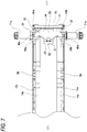
Fig. 7] Fig. 7 is a view when the inner pad, the outer pad and the pad spring are taken out and viewed from a radially outer side. - [
Fig. 8] Fig. 8 is a view when the inner pad, the outer pad and the pad spring are taken out and viewed from one peripheral side. - [
Fig. 9] Fig. 9 is a perspective view showing the inner pad, the outer pad and the pad spring taken out and partially omitted. - [
Fig. 10A] Fig. 10A is a front view showing the pad spring taken out. - [
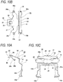
Fig. 10B] Fig. 10B is a plan view showing the pad spring taken out. - [
Fig. 10C] Fig. 10C is a right side view showing the pad spring taken out. - [
Fig. 11] Fig. 11 is a perspective view showing the pad spring taken out. - [
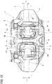
Fig. 12] Fig. 12 is a diagram corresponding toFig. 5 showing a second example of the pad embodiment. - [
Fig. 13] Fig. 13 is a plan view showing a disc brake device having a structure according to related art. - [
Fig. 14] Fig. 14 is a B-B cross-sectional view ofFig. 13 . - [
Fig. 15A] Fig. 15A is front view showing the pad taken out in a state during forward braking. - [
Fig. 15B] Fig. 15B is front views showing the pad taken out in a state during reverse braking. - A first example of an embodiment of the present invention will be described with reference to
Figs. 1 to 11 . - A
disc brake device 1a of the present example is an opposed piston type disc brake device that is used for braking an automobile. Thedisc brake device 1a includes acaliper 2a corresponding to the pad support member, a pair of aninner pad 3a and anouter pad 4a, and a disc brake pad spring (hereinafter, referred to as a pad spring) 23 that elastically presses theinner pad 3a and theouter pad 4a. - In the present embodiment, an axial direction (X), a circumferential direction (Y), and a radial direction (Z) refer to an axial direction, a circumferential direction, and a radial direction of a disc-shaped rotor 5 (see
Fig. 2 ) that rotates together with a wheel unless otherwise specified. Front-back directions ofFigs. 1 ,4 ,5 , and6 , upper-lower directions ofFigs. 2 and7 , and left-right directions ofFig. 8 correspond to the axial direction, where a side close to therotor 5 in the axial direction (X) is referred to as an axially inner side, and a side far from therotor 5 in the axial direction (X) is referred to as an axially outer side. Left-right directions ofFigs. 1 ,2 ,4 ,5 ,6 , and7 and front-back directions ofFig. 8 correspond to the circumferential direction (Y), where right sides ofFigs. 1 ,2 ,4 ,5 ,6 , and7 and a front side ofFig. 8 are referred to as one peripheral side (Y1), and left sides ofFigs. 1 ,2 ,4 ,5 ,6 , and7 and a back side ofFig. 8 are referred to as the other peripheral side (Y2), respectively. In the present embodiment, the one peripheral side (Y1) is a rotation-in side when a vehicle is travelling forward and a rotation-out side when the vehicle is traveling reversely, and the other peripheral side (y2) is the rotation-out side when the vehicle is travelling forward and the rotation-in side when the vehicle is traveling reversely. Upper-lower directions ofFigs. 1 ,4 ,5 ,6 , and8 and front-back directions ofFigs. 2 and7 corresponds to the radial direction (Z), upper sides ofFigs. 1 ,4 ,5 ,6 , and8 , front sides ofFigs. 2 and7 correspond to a radially outer side, and lower sides ofFigs. 1 ,4 ,5 ,6 , and8 and back sides ofFigs. 2 and7 corresponds to a radially inner side. The rotation-in side refers to a side from which therotor 5 enters thecaliper 2a, and the rotation-out side refers to a side from which therotor 5 comes out of thecaliper 2a. - The
caliper 2a is supported by the pair of theinner pad 3a and theouter pad 4a to be movable in the axial direction (X), and is integrally formed by performing a casting processing or the like on a light alloy such as an aluminum alloy or a material made of an iron-based alloy. Thecaliper 2a includes aninner body 6a and anouter body 7a being located to sandwich therotor 5, a rotation-inside coupling part 8 and a rotation-outside coupling part 9a each of which connects peripheral-direction two-end parts of theinner body 6a with peripheral-direction two-end parts of theouter body 7 respectively, andcenter bridges inner body 6a with a peripheral intermediate part of theouter body 7a. The pair ofcenter bridges window portion 24 communicating in the radial direction (Z) is provided between the rotation-inside coupling part 8a and thecenter bridge 10a on the one peripheral side (Y1). - The
inner body 6a and theouter body 7a respectively have a plurality (three in the illustrated example) ofinner cylinders 25 andouter cylinders 26. An inner piston and an outer piston (not shown) are fitted respectively on inner sides of theinner cylinders 25 and inner sides of theouter cylinders 26 to be liquid-tight and displaceable in the axial direction (X). Thecaliper 2a is supported and fixed onto a knuckle of a suspension device by a pair of mountingseats 27 provided in theinner body 6a in a state of covering therotor 5 from the radially outer sides. - A pair of
pins 11a are coaxially supported and fixed (fixedly installed) in the axial direction (X) with respect to each other at radially inner side parts of peripheral-direction one-side parts of theinner body 6a and theouter body 7a. Tip parts of thepins 11a respectively protrude from axially inner side surfaces that face each other of theinner body 6a and theouter body 7a, and face two axial side surfaces of therotor 5 with gaps therebetween. A portion of each of thepins 11a protruding from the axially inner side surfaces of theinner body 6a and theouter body 7a has a substantially columnar shape and has an outer peripheral surface shape of a cylindrical surface. During forward braking, thepins 11a are respectively engaged with throughholes 16a provided in each of theinner pad 3a and theouter pad 4a so as to bear the brake tangential force F1 acting on theinner pad 3a and theouter pad 4a. - As shown in
Fig. 14 , guide walls protruding in the axial direction (X) are respectively provided on axially inner side surfaces that face each other of peripheral-direction other-side parts of theinner body 6a and theouter body 7a. Each guide wall has, at a radially intermediate part thereof, a guide groove opening toward the axially inner side surface and a peripheral-direction one-side surface. - A surface facing the
center bridge 10a in the circumferential direction (Y) of the rotation-inside coupling part 8a is a flattorque receiving surface 18a. Thetorque receiving surface 18a is on a virtual plane orthogonal to a brake tangential force. During reverse braking, thetorque receiving surface 18a is engaged withtorque transmission surfaces 19a respectively provided on theinner pad 3a and theouter pad 4a, which will be describe later, so as to bear a brake tangential force F2 acting on theinner pad 3a and theouter pad 4a. - Each of the
inner pad 3a and theouter pad 4a includes a lining (friction material) 14a and a metal back plate (pressure plate) 15a supporting a back surface of thelining 14a. In this example, shapes of peripheral-direction two-end parts of each of theback plates 15a constituting theinner pad 3a and theouter pad 4a are asymmetric with respect to the circumferential direction (Y). - Specifically, a radially inner side part of a peripheral-direction one-end part (rotation-in side end part) of each
back plate 15a has a shape protruding in the circumferential direction (Y) from thelining 14a. This part is referred to as a substantially triangular plate shaped protrudingportion 28. A part of the protrudingportion 28 that is located on a radially inner side relative to an action line of a brake tangential force that acts during braking (frictional surface center point A) is formed with the throughhole 16a, which penetrates in the axial direction (X) and has a substantially rectangular shape. In a peripheral-direction one-side surface of theback plate 15a, a radially outer side end part located on the radially outer side relative to the action line of the brake tangential force that acts during braking is provided with a flattorque transmission surface 19a that faces thetorque receiving surface 18a in the circumferential direction (Y). In the peripheral-direction one-side surface of theback plate 15a, a part between thetorque transmission surface 19a and the protrudingportion 28 is recessed toward the other peripheral side (Y2) relative to thetorque transmission surface 19a and the protrudingportion 28. A radially outer end part of the peripheral-direction one-end part of theback plate 15a is provided with a projectingportion 29 protruding toward the radially outer side relative to a portion adjacent to the other peripheral side (Y2). - On the other hand, although omitted in the drawings, a radially inner side part of a peripheral-direction other-end part (rotation-out side end part) of the
back plate 15a has a shape along thelining 14a, but does not have a protruding portion protruding in the circumferential direction (Y) from thelining 14a. Theback plate 15a includes, at a radially intermediate part on a peripheral-direction other-side surface, aconvex ear portion 17a projecting toward the other peripheral side (Y2). During braking (forward braking and reverse braking), a radially inner side surface of theear portion 17a abuts against a radially inner side surface of the guide groove, so as to bear a moment (rotation force) acting on theinner pad 3a and theouter pad 4a. - In order to support the
inner pad 3a and theouter pad 4a to be movable in the axial direction (X) with respect to thecaliper 2a, thepins 11a respectively supported by theinner body 6a and theouter body 7a are loosely inserted in the axial direction (X) into the throughholes 16a provided on therespective back plates 15a constituting theinner pad 3a and theouter pad 4a. Theear portions 17a provided on therespective back plates 15a constituting theinner pad 3a and theouter pad 4a are engaged with the guide grooves respectively provided in theinner body 6a and theouter body 7a to be movable in the axial direction (X). In this state, thetorque transmission surface 19a provided on the peripheral-direction one-side surface of eachback plate 15a faces thetorque receiving surface 18a provided on the rotation-inside coupling part 8a in the circumferential direction (Y). - In the
disc brake device 1a according to the present embodiment, the same moment as that in the structure illustrated inFigs. 13 to 15B described above is generated on theinner pad 3a and theouter pad 4a during braking. - During forward braking, as illustrated in
Fig. 4 , the brake tangential force F1 directed to the other peripheral side (left side inFig. 4 , rotation-out side) acts on the friction surface center point A of thelining 14a. The throughhole 16a is engaged with thepin 11a to bear the brake tangential force F1 (so-called pull anchor structure). For this reason, during forward braking, the moment M1 in a direction in which the peripheral-direction other-side part is pressed down toward the radially inner side acts on theinner pad 3a and theouter pad 4a. The friction surface center point A is a centroid of a friction surface, which is determined by a diameter, an arrangement, and the like of a piston. - During reverse braking, a brake tangential force F2 directed to the one peripheral side (right side in
Fig. 4 , rotation-out side) acts on the friction surface center point A of thelining 14a. Thetorque receiving surface 18a is abutted against thetorque transmission surface 19a to bear the brake tangential force F2 (so-called push anchor structure). For this reason, during reverse braking, the moment M2 in the direction in which the peripheral-direction other-side part is pressed down toward the radially inner side (in the same direction as M1) acts on theinner pad 3a and theouter pad 4a. - Therefore, according to the
disc brake device 1a according to the present example, directions of the moments M1, M2 acting on theinner pad 3a and theouter pad 4a can be the same during forward braking and reverse braking. For this reason, postures of theinner pad 3a and theouter pad 4a can be maintained in a state of being rotated counterclockwise even when the forward braking and the reverse braking are repeated as when the vehicle enters a garage or the like. Therefore, since the postures of theinner pad 3a and theouter pad 4a does not need to be changed, crunch sound can be prevented. - Next, the
pad spring 23 that elastically presses theinner pad 3a and theouter pad 4a will be described. In this example, asingle pad spring 23 is attached to peripheral-direction one-side part of thecaliper 2a. A pad spring (including a pad clip) other than thepad spring 23 can be attached to a peripheral-direction other-side part of thecaliper 2a, as necessary. - As shown in
Figs. 10A to 11 , thepad spring 23 is formed by bending a single metal plate having elasticity and corrosion resistance, such as a stainless steel plate, and is bent in a substantially L shape as a whole. Thepad spring 23 has a radially outer side part disposed inside thewindow portion 24, and has a radially intermediate part to inner part disposed on the one peripheral side (Y1) of theinner pad 3a and theouter pad 4a. Thepad spring 23 includes a lockingportion 30, a substantially U-shaped firstbifurcated portion 31, a pair of flat sandwichedportions 32, and a substantially U-shaped secondbifurcated portion 33 in order from the other peripheral side (Y2) to the one side (from the radially outer side to inner side), and theentire pad spring 23 is symmetrical with respect to the axial direction (X). The firstbifurcated portion 31 and the secondbifurcated portion 33 are connected to each other by acoupling plate portion 34 extending in the radial direction (Z), and the pair of sandwichedportions 32 are disposed on two sides in the axial direction of thecoupling plate portion 34. - The locking
portion 30 has a substantially L-shape and is elastically locked to a peripheral-direction one-end part of thecenter bridge 10a. The lockingportion 30 includes a rectangular plate-shaped push-upplate portion 35 that abuts against a radially inner side surface of thecenter bridge 10a, and anupright plate portion 36 that is bent from a peripheral-direction one-end part of the push-upplate portion 35 toward the radially outer side. An axially intermediate part of theupright plate portion 36 is formed with a bent-upportion 37 formed by bending up an inner portion of a substantially U-shaped notch toward the other peripheral side (Y2). The push-upplate portion 35 elastically presses the radially inner side surface of thecenter bridge 10a toward the radially outer side. The bent-upportion 37 elastically presses a peripheral-direction one-side surface of thecenter bridge 10a toward the other peripheral side (Y2). - In an attached state of the
pad spring 23, the firstbifurcated portion 31 is disposed inside thewindow portion 24, and elastically presses peripheral-direction one-side part of the outer peripheral edge of therespective back plates 15a constituting theinner pad 3a and theouter pad 4a. The firstbifurcated portion 31 includes a firstbase plate portion 38 having a substantially flat plate shape extending in the axial direction (X) and a pair of firstpressing parts base plate portion 38 has a peripheral-direction other-end part connected to a radially outer end part of theupright plate portion 36, and is inclined toward the radially inner side as it moves toward the one peripheral side (Y1). - The first
pressing parts base plate portion 38. The firstpressing parts base plate portion 38 toward the other peripheral side (Y2) and are folded back by 180 degrees toward the radially inner side and toward the one peripheral side (Y1) from the respective intermediate parts. Distal parts (radially inner end part) of the firstpressing parts back portions back portions pressing parts back portions back portions respective back plates 15a constituting theinner pad 3a and theouter pad 4a toward the radially inner side and toward the axially outer side. In this example, the first fold-back portions pin 11a and is located the other peripheral side (Y2) relative to the projectingportion 29 provided at the peripheral-direction one-end part, in the outer peripheral edge of theback plate 15a. - In the attached state of the
pad spring 23, the secondbifurcated portion 33 is disposed on the one peripheral side (Y1) of theinner pad 3a and theouter pad 4a, and elastically presses radially intermediate part of the peripheral-direction one-side surface of therespective back plates 15a constituting theinner pad 3a and theouter pad 4a. The secondbifurcated portion 33 includes a secondbase plate portion 41 extending in the axial direction (X) and a pair of secondpressing parts base plate portion 41 has an axially intermediate part of a radially outer end part connected to thecoupling plate portion 34, and has a radially intermediate part to inner end part inclined toward the one peripheral side (Y1) as it moves toward the radially inner side. The secondpressing parts base plate portion 41. The secondpressing parts base plate portion 41 toward the radially inner side, and have peripheral-direction one-side surfaces twisted to face each other. Distal parts (radially inner end part) of the secondpressing parts back portions back portions pressing parts back portions back portions respective back plates 15a constituting theinner pad 3a and theouter pad 4a toward the other peripheral side (Y2) and toward the axially outer side. - In this example, as shown in
Fig. 5 , a third radial position P3 where the second fold-back portions back plates 15a is located between a first radial position P1 on which the first fold-back portions back plates 15a and a second radial position P2 that is an abutting position between the radially outer side surfaces of the inner peripheral surfaces of the throughholes 16a and radially outer end parts of the outer peripheral surfaces of thepins 11a. In particular, in this example, theinner pad 3a and theouter pad 4a are pressed in directions away from each other in the axial direction (X) by the first fold-back portions - The
coupling plate portion 34 is formed in a substantially flat plate shape and extends in the radial direction (Z). Thecoupling plate portion 34 connects an axially intermediate part of a peripheral-direction one-end part of the firstbase plate portion 38 constituting the firstbifurcated portion 31 and an axially intermediate part of a radially outer end part of the secondbase plate portion 41 forming the secondbifurcated portion 33 with each other. - The pair of sandwiched
portions 32 are each formed in a flat plate shape, and are disposed on two axial sides of a radially intermediate part of thecoupling plate portion 34. - In the
pad spring 23 as described above, the push-upplate portion 35 and the pair of firstpressing parts center bridge 10a and the outer peripheral edges of theback plates 15a, so as to be attached to (elastically supported by) thedisc brake device 1a. In such an attached state, the pair of firstpressing parts respective back plates 15a constituting theinner pad 3a and theouter pad 4a toward the radially inner side and toward the axially outer side. The pair of secondpressing parts respective back plates 15a constituting theinner pad 3a and theouter pad 4a toward the other peripheral side (Y2) and toward the axially outer side. The pair of sandwichedportions 32 are positioned between the torque transmission surfaces 19a and thetorque receiving surface 18a. - According to the
pad spring 23 as described above, it is possible to not only prevent occurrence of brake noise in a non-braking state, but also prevent occurrence of abnormal noise based on collision between the throughholes 16a formed in theback plates 15a and thepins 11a supported on thecaliper 2a during forward braking. - That is, the pair of first
pressing parts back portions pad spring 23 elastically press the peripheral-direction one-side parts of the outer peripheral edges of theback plates 15a toward the radially inner side. Therefore, in the non-braking state, the radially outer side surfaces of the inner peripheral surfaces of the throughholes 16a can abut against the radially outer side end parts of the outer peripheral surfaces of thepins 11a, and the radially inner side surfaces of theear portions 17a can abut against the radially inner side surfaces of the guide grooves. Moreover, in this example, since the first fold-back portions back plates 15a that overlap in the radial direction (Z) with thepins 11a, the inner peripheral surfaces of the throughholes 16a can be reliably pressed against the outer peripheral surfaces of thepins 11a due to a pressing force of the firstpressing parts inner pad 3a and theouter pad 4a can be stabilized even in the non-braking state, and brake noise can be prevented. - The pair of second
pressing parts back portions back plates 15a toward the other peripheral side (Y2). Therefore, in the non-braking state, the peripheral-direction one-side surfaces of the inner peripheral surfaces of the throughholes 16a can keep abuting against the peripheral-direction one-end parts of the outer peripheral surfaces of thepins 11a. Therefore, during forward braking, even when the brake tangential force F1 directed to the other peripheral side (Y2) acts on the friction surface center point A of thelinings 14a, it is possible to prevent theinner pad 3a and theouter pad 4a from moving toward the other peripheral side (Y2), and prevent the throughholes 16a and thepins 11a from collision. As a result, it is possible to prevent occurrence of abnormal noise based on the collision between the throughholes 16a and thepins 11a. - The pair of first
pressing parts back portions pressing parts back portions inner pad 3a and theouter pad 4a in directions away from each other with respect to the axial direction (X). Therefore, in the non-braking state, the side surface of therespective linings 14a constituting theinner pad 3a and theouter pad 4a can be separated from the side surface of therotor 5, and these side surfaces can be prevented from friction. Therefore, it is possible to prevent drag of theinner pad 3a and theouter pad 4a, and to prevent occurrence of judder. - In addition, the third radial position P3 in which the second
pressing parts back portions back plates 15a is located closer to the second radial position P2 than the central part C between the first radial position P1 and the second radial position P2. Therefore, theinner pad 3a and theouter pad 4a can be separated from each other in the axial direction (X) without greatly inclining with abutting portions between the throughholes 16a and thepins 11a as a fulcrum. The reason for this will be described below. - A force (Fy) directed to the radially inner side and acting on the outer peripheral edges of the
back plates 15a from the pair of firstpressing parts holes 16a and the radially outer end parts of the outer peripheral surfaces of thepins 11a. Therefore, a reaction force {f2 = pressing force (Fy) × friction coefficient (µ2) between throughholes 16a and pins 11a} against a force (Fx1) directed to the axially outer side and acting on theback plates 15a from the firstpressing parts holes 16a and thepins 11a. Therefore, theinner pad 3a and theouter pad 4a tend to incline so that the radially outer side parts thereof are separated from each other with the abutting portions between the throughholes 16a and thepins 11a as a fulcrum. Therefore, when the third radial position P3 approaches the first radial position PI, the inclination of theinner pad 3a and theouter pad 4a is likely to become larger, and it becomes difficult to move theinner pad 3a and theouter pad 4a away from each other. Therefore, in this example, the third radial position P3 is located closer to the second radial position P2 than a central part C between the first radial position P1 and the second radial position P2. Thereby, it is possible to move theinner pad 3a and theouter pad 4a away from each other without increasing the inclination of theinner pad 3a and theouter pad 4a. - Further, since the pair of sandwiched
portions 32 constituting thepad spring 23 are disposed between the torque transmission surfaces 19a and thetorque receiving surface 18a, it is possible to prevent occurrence of rust on the torque transmission surfaces 19a and thetorque receiving surface 18a. In addition, theback plates 15a constituting theinner pad 3a and theouter pad 4a can be smoothly displaced in the axial direction (X) with respect to thecaliper 2a. - Further, since the first
bifurcated portion 31 can be exposed to thewindow portion 24 in the attachment state of thepad spring 23, it is easy to prevent forgetting to attach thepad spring 23. In addition, since the throughholes 16a have a rectangular hole shape and thepins 11a have a circular cross-sectional shape, a contact state when the outer peripheral surfaces of thepins 11a abut against the inner peripheral surfaces of the throughholes 16a can be line contact. Therefore, the contact state between thepins 11a and the throughholes 16a can be stabilized. - Other configurations and operational effects are the same as those of the structure of the related art as described above.
- A second example of the embodiment of the present invention will be described with reference to
Fig. 12 . - In this example, first fold-
back portions pressing parts pad spring 23a are not inclined to the radial direction (Z), but are arranged in the axial direction (X) (linearly). Therefore, the firstpressing parts back portions respective back plates 15a constituting theinner pad 3a and theouter pad 4a toward the radially inner side, without pressing toward the axially outer side. Therefore, in this example, the third radial position P3 in which secondpressing parts back portions back plates 15a are different from the first example of the embodiment. - Specifically, the third radial position P3 is located in the vicinity of the central part C between the first radial position P1 on which the first
pressing parts back plates 15a and the second radial position P2 that is an abutting position between the radially outer side surfaces of the inner peripheral surfaces of the throughholes 16a and the radially outer end parts of the outer peripheral surfaces of thepins 11a. - In this example, a force (Fx2) directed toward the axially outer side acts on the
inner pad 3a and theouter pad 4a from only the secondpressing parts back plates 15a from the secondpressing parts pressing parts back plates 15a and the abutting portions between the throughholes 16a and thepins 11a. Specifically, a reaction force corresponding to the product of the force (Fy) directed toward the radially inner side and acting on theback plates 15a from the firstpressing parts pressing parts back plates 15a {f1 = pressing force (Fy) ×friction coefficient (µ1)} acts on the abutting portions between the firstpressing parts back plates 15a. On the other hand, a reaction force corresponding to the product of the force (Fy) directed toward the radially inner side and acting on theback plates 15a from the firstpressing parts holes 16a and thepins 11a {f2 = pressing force (Fy) ×friction coefficient (µ2)} acts on the abutting portions between the radially outer side surfaces of the inner peripheral surfaces of the throughholes 16a and the radially outer end parts of the outer peripheral surfaces of thepins 11a. - Therefore, in the present example, in order to separate the
inner pad 3a and theouter pad 4a from each other in the axial direction (X), the force (Fx2) directed toward the axially outer side, which is applied to theback plates 15a from the secondpressing parts pressing parts back plates 15a and the reaction force (f2) acting on the abutting portions between the throughholes 16a and thepins 11a (Fx2 ≥ f1+f2). - In order to separate the
inner pad 3a and theouter pad 4a from each other in the axial direction (X) without causing inclination of theinner pad 3a or theouter pad 4a, the third radial position P3 is preferably set such that a ratio of the reaction force (f1) acting on the he abutting portions between the firstpressing parts back plates 15a to the reaction force (f2) acting on the abutting portions between the throughholes 16a and thepins 11a is the same as a ratio of a radial distance (L1) from the third radial position P3 to the first radial position P1 to a radial distance (L2) from the third radial position P3 to the second radial position P2 (f1 : f2 = L1 : L2). In this example, since the friction coefficient (µ1) between the firstpressing parts back plates 15a and the friction coefficient (µ2) between the throughholes 16a and thepins 11a are substantially the same, the third radial position P3 is disposed in the vicinity of the central part C between the first radial position P1 and the second radial position P2. - In the present example as described above, the
inner pad 3a and theouter pad 4a can be separated from each other in the axial direction (X) without causing inclination of theinner pad 3a or theouter pad 4a by the secondpressing parts - Other configurations and operational effects are the same as those of the first example of the embodiment.
- The disc brake pad spring of the present invention is not limited to the opposed-piston type disc brake device as described in the embodiment, and can also be applied to a floating caliper type disc brake device. Further, the support structure of the pads on the pad support member at the peripheral-direction other-side part of the disc brake device is not limited to the structures described in the examples of the embodiment in which the convex ear portions are engaged with the guide grooves, and other support structures such as a structure that supports the pads using pins, for example, can be adopted.
- Here, features of the disc brake pad spring and the disc brake device according to the present invention described above will be briefly summarized below.
- [1] A disc brake pad spring configured to be attached to a disc brake device (1a) in which a pair of pads (
inner pad 3a andouter pad 4a) located to sandwich a rotor (5) are supported with respect to a pad support member (caliper 2a) by inserting in an axial direction (X) pins (11a) provided on the pad support member into a through hole (16a) formed in a radially inner side part of a peripheral-direction one-side part of a back plate (15a) of each of the pair of pads, and configured to elastically press the pair of pads against the pad support member, in which
the disc brake pad spring (pad spring - a pair of first pressing parts (39a, 39b, 39c, 39d) configured to press a peripheral-direction one-side part of an outer peripheral edge of the respective back plates of each of the pair of pads toward a radially inner side, and
- a pair of second pressing parts (42a,42b, 42c, 42d) configured to press a peripheral-direction one-side surface of the respective back plates of each of the pair of pads toward the other peripheral side.
- [2] The disc brake pad spring (pad spring 23) according to [1], in which
the pair of second pressing parts (42a, 42b) are configured to press the pair of pads (inner pad 3a andouter pad 4a) in directions away from each other in the axial direction (X). - [3] The disc brake pad spring (
pad spring 23a) according to [2], in which
a radial position (third radial position P3) in which the pair of second pressing parts (42c, 42d) respectively press the back plates (15a) is located between a first radial position (PI) on which the pair of first pressing parts (39c, 39d) respectively press the back plate and a second radial position (P2) that is an abutting position between inner peripheral surfaces of the through holes (16a) and radially outer side parts of outer peripheral surfaces of the pins (11a). - [4] The disc brake pad spring (
pad spring 23a) according to [3], in which
when the pair of first pressing parts (39c, 39d) press the pair of pads (inner pad 3a andouter pad 4a) in the directions away from each other in the axial direction (X), the pair of second pressing parts (42c, 42d) respectively press portions closer to the second radial position (P2) than a central part (C1) between the first radial position (PI) and the second radial position. - [5] The disc brake pad spring (
pad spring 23a) according to [3], in which
when the pair of first pressing parts (39c, 39d) do not press the pair of pads (inner pad 3a andouter pad 4a) in the directions away from each other in the axial direction (X), the pair of second pressing parts (42c, 42d) respectively press the vicinity of a central part (C1) between the first radial position (PI) and the second radial position (P2). - [6] The disc brake pad spring (pad spring 23) according to any one of [1] to [2], in which
the pair of first pressing parts (39a, 39b) are configured to press the pair of pads (inner pad 3a andouter pad 4a) in directions away from each other in the axial direction (X). - [7] The disc brake pad spring (
pad spring
the back plate (15) of each of the pair of pads (inner pad 3a andouter pad 4a) has a torque transmission surface (19a) in the peripheral-direction one-side surface, and the torque transmission surface abuts against a torque receiving surface (18a) provided on the pad support member (caliper 2a) so as to bear a brake tangential force acting on each of the pair of pads during reverse braking, and
the disc brake pad spring further includes a pair of sandwiched portions, the pair of sandwiched portions (32) each being disposed between the torque transmission surface and the torque receiving surface. - [8] The disc brake pad spring (
pad spring
each of the pair of first pressing parts (39a,39b, 39c, 39d) is configured to press a part of the outer peripheral edge of the back plate (15a) that overlaps in a radial direction with the pin (11a). - [9] A disc brake device (1a), including:
- a pair of pads (
inner pad 3a andouter pad 4a) each including a lining (14a) and a back plate (15a) that supports a back surface of the lining, and located to sandwich a rotor (5); - a pad support member (
caliper 2a) that supports the pair of pads to be movable in an axial direction (X); and - a disc brake pad spring configured to elastically press the pair of pads, in which
- each of the back plates of the pair of pads has a through hole (16a) on a radially inner side part of a peripheral-direction one-side part,
- the pad support member includes a pair of pins (11a) inserted into the respective through holes in the axial direction, and
- the disc brake pad spring is the disc brake pad spring according to any one of [1] to [8] (
pad spring
- a pair of pads (
- Although the embodiments are described above with reference to the drawings, it is needless to say that the present invention is not limited to such examples. It will be apparent to those skilled in the art that various changes and modifications may be conceived within the scope of the claims. It is also understood that the various changes and modifications belong to the technical scope of the present invention. Constituent elements in the embodiments described above may be combined freely within a range not departing from the spirit of the present invention.
- The present application is based on
Japanese Patent Application No. 2018-177896 filed on September 21, 2018 - According to the disc brake pad spring and the disc brake device of the present invention, it is possible to prevent occurrence of brake noise in the non-braking state. Further, it is possible to prevent occurrence of abnormal noise based on collision between a through hole formed in a back plate of a pad and a pin provided on a pad support member during forward braking
-
- 1, 1a
- disc brake device
- 2, 2a
- caliper (pad support member)
- 3, 3a
- inner pad
- 4, 4a
- outer pad
- 5
- rotor
- 6, 6a
- inner body
- 7, 7a
- outer body
- 8, 8a
- rotation-in side coupling part
- 9, 9a
- rotation-out side coupling part
- 10, 10a, 10b
- center bridge
- 11, 11a
- pin
- 12
- guide groove
- 13
- guide wall
- 14, 14a
- lining
- 15, 15a
- back plate
- 16, 16a
- through hole
- 17, 17a
- ear portion
- 18, 18a
- torque receiving surface
- 19, 19a
- torque transmission surface
- 20
- pad spring
- 21a, 21b
- rotation-in side pressing part
- 22a, 22b
- rotation-out side pressing part
- 23, 23a
- pad spring (disk brake pad spring)
- 24
- window portion
- 25
- inner cylinder
- 26
- outer cylinder
- 27
- mounting seat
- 28
- protruding portion
- 29
- projecting portion
- 30
- locking portion
- 31
- first bifurcated portion
- 32
- sandwiched portion
- 33
- second bifurcated portion
- 34
- coupling plate portion
- 35
- push-up plate portion
- 36
- upright plate portion
- 37
- bent-up portion
- 38
- first base plate portion
- 39a, 39b, 39c, 39d
- first pressing part
- 40a, 40b, 40c, 40d
- first fold-back portion
- 41
- second base plate portion
- 42a, 42b, 42c, 42d
- second pressing part
- 43a, 43b, 43c, 43d
- second fold-back portion
Claims (9)
- A disc brake pad spring configured to be attached to a disc brake device in which a pair of pads located to sandwich a rotor are supported with respect to a pad support member by inserting in an axial direction pins provided on the pad support member into a through hole formed in a radially inner side part of a peripheral-direction one-side part of a back plate of each of the pair of pads, and configured to elastically press the pair of pads against the pad support member, wherein
the disc brake pad spring is formed by a single metal plate, and comprises:a pair of first pressing parts configured to press a peripheral-direction one-side part of an outer peripheral edge of the respective back plates of each of the pair of pads toward a radially inner side, anda pair of second pressing parts configured to press a peripheral-direction one-side surface of the respective back plates of each of the pair of pads toward the other peripheral side. - The disc brake pad spring according to claim 1, wherein
the pair of second pressing parts are configured to press the pair of pads in directions away from each other in the axial direction. - The disc brake pad spring according to claim 2, wherein
a radial position in which the pair of second pressing parts respectively press the back plates is located between a first radial position on which the pair of first pressing parts respectively press the back plate and a second radial position that is an abutting position between inner peripheral surfaces of the through holes and radially outer side parts of outer peripheral surfaces of the pins. - The disc brake pad spring according to claim 3, wherein
when the pair of first pressing parts press the pair of pads in the directions away from each other in the axial direction, the pair of second pressing parts respectively press portions closer to the second radial position than a central part between the first radial position and the second radial position. - The disc brake pad spring according to claim 3, wherein
when the pair of first pressing parts do not press the pair of pads in the directions away from each other in the axial direction, the pair of second pressing parts press the vicinity of a central part between the first radial position and the second radial position. - The disc brake pad spring according to any one of claims 1 to 2, wherein
the pair of first pressing parts are configured to press the pair of pads in directions away from each other in the axial direction. - The disc brake pad spring according to any one of claims 1 to 6, wherein
the back plate of each of the pair of pads has a torque transmission surface in the peripheral-direction one-side surface, and the torque transmission surface abuts against a torque receiving surface provided on the pad support member so as to bear a brake tangential force acting on each of the pair of pads during reverse braking, and
the disc brake pad spring further comprises a pair of sandwiched portions, the pair of sandwiched portions each being disposed between the torque transmission surface and the torque receiving surface. - The disc brake pad spring according to any one of claims 1 to 7, wherein
each of the pair of first pressing parts is configured to press a part of the outer peripheral edge of the back plate that overlaps in a radial direction with the pins. - A disc brake device, comprising:a pair of pads each including a lining and a back plate that supports a back surface of the lining, and located to sandwich a rotor;a pad support member that supports the pair of pads to be movable in an axial direction; anda disc brake pad spring configured to elastically press the pair of pads, whereineach of the back plates of the pair of pads has a through hole on a radially inner side part of a peripheral-direction one-side part,the pad support member includes a pair of pins inserted into the respective through holes in the axial direction, andthe disc brake pad spring is the disc brake pad spring according to any one of claims 1 to 8.
Applications Claiming Priority (2)
| Application Number | Priority Date | Filing Date | Title |
|---|---|---|---|
| JP2018177896A JP7110049B2 (en) | 2018-09-21 | 2018-09-21 | Disc brake pad spring and disc brake device |
| PCT/JP2019/036829 WO2020059823A1 (en) | 2018-09-21 | 2019-09-19 | Pad spring for disc brake and disc brake device |
Publications (3)
| Publication Number | Publication Date |
|---|---|
| EP3855040A1 true EP3855040A1 (en) | 2021-07-28 |
| EP3855040A4 EP3855040A4 (en) | 2022-03-30 |
| EP3855040B1 EP3855040B1 (en) | 2023-07-19 |
Family
ID=69887159
Family Applications (1)
| Application Number | Title | Priority Date | Filing Date |
|---|---|---|---|
| EP19862288.8A Active EP3855040B1 (en) | 2018-09-21 | 2019-09-19 | Pad spring for disc brake and disc brake device |
Country Status (5)
| Country | Link |
|---|---|
| US (1) | US11754133B2 (en) |
| EP (1) | EP3855040B1 (en) |
| JP (1) | JP7110049B2 (en) |
| CN (1) | CN112739927B (en) |
| WO (1) | WO2020059823A1 (en) |
Families Citing this family (5)
| Publication number | Priority date | Publication date | Assignee | Title |
|---|---|---|---|---|
| EP4206486A4 (en) * | 2020-08-25 | 2024-09-25 | Hitachi Astemo, Ltd. | DISC BRAKE DEVICE |
| IT202100000743A1 (en) * | 2021-01-18 | 2022-07-18 | Brembo Spa | RIBBON SPRING AND SPRING RIBBON AND BRAKE PAD ASSEMBLY |
| IT202100000749A1 (en) * | 2021-01-18 | 2022-07-18 | Brembo Spa | RIBBON SPRING AND SPRING RIBBON AND BRAKE PAD ASSEMBLY |
| JP7618512B2 (en) | 2021-07-07 | 2025-01-21 | 曙ブレーキ工業株式会社 | Pad clip for disc brake device and disc brake device |
| US12005991B2 (en) | 2021-12-03 | 2024-06-11 | Shimano Inc. | Brake caliper for a bicycle |
Family Cites Families (14)
| Publication number | Priority date | Publication date | Assignee | Title |
|---|---|---|---|---|
| US4422534A (en) * | 1979-11-20 | 1983-12-27 | Tokico Ltd. | Disc brake |
| JPS6058935U (en) * | 1983-09-29 | 1985-04-24 | アイシン精機株式会社 | Integral type disc brake |
| JPH11236935A (en) * | 1998-02-23 | 1999-08-31 | Sumitomo Electric Ind Ltd | Disc brake device |
| WO2005064188A1 (en) | 2003-12-30 | 2005-07-14 | Freni Brembo S.P.A. | Brake pad and caliper for a disc brake |
| EP1921853A1 (en) * | 2005-07-26 | 2008-05-14 | Matsushita Electric Industrial Co., Ltd. | Image data management device and image data management method |
| DE102008020346A1 (en) * | 2008-04-23 | 2009-10-29 | Lucas Automotive Gmbh | Disk brake for motor vehicle brake system, has lining retaining spring fixed to housing cross beam with contact surface and positionably engaged to beam with retaining plates that are angled against contact surface |
| JP2012180905A (en) * | 2011-03-02 | 2012-09-20 | Nissin Kogyo Co Ltd | Vehicle disc brake |
| JP5858244B2 (en) | 2013-04-25 | 2016-02-10 | 株式会社アドヴィックス | Disc brake device |
| JP6261289B2 (en) | 2013-11-07 | 2018-01-17 | 曙ブレーキ工業株式会社 | Disc brake pad spring |
| JP6189718B2 (en) * | 2013-11-07 | 2017-08-30 | 曙ブレーキ工業株式会社 | Disc brake pad and disc brake device |
| CN106715945B (en) * | 2014-11-19 | 2019-03-08 | 日立汽车系统株式会社 | Disc brakes |
| JP6299650B2 (en) * | 2015-03-31 | 2018-03-28 | 株式会社アドヴィックス | Disc brake device |
| CN108291597B (en) * | 2015-11-26 | 2020-01-03 | 日立汽车系统株式会社 | Disc brake |
| JP6498716B2 (en) | 2017-04-07 | 2019-04-10 | 花王株式会社 | Ground improvement method |
-
2018
- 2018-09-21 JP JP2018177896A patent/JP7110049B2/en active Active
-
2019
- 2019-09-19 CN CN201980061842.9A patent/CN112739927B/en active Active
- 2019-09-19 WO PCT/JP2019/036829 patent/WO2020059823A1/en not_active Ceased
- 2019-09-19 EP EP19862288.8A patent/EP3855040B1/en active Active
- 2019-09-19 US US17/278,036 patent/US11754133B2/en active Active
Also Published As
| Publication number | Publication date |
|---|---|
| CN112739927A (en) | 2021-04-30 |
| JP2020051437A (en) | 2020-04-02 |
| US20210348661A1 (en) | 2021-11-11 |
| WO2020059823A1 (en) | 2020-03-26 |
| US11754133B2 (en) | 2023-09-12 |
| JP7110049B2 (en) | 2022-08-01 |
| CN112739927B (en) | 2023-03-17 |
| EP3855040B1 (en) | 2023-07-19 |
| EP3855040A4 (en) | 2022-03-30 |
Similar Documents
| Publication | Publication Date | Title |
|---|---|---|
| EP3855040B1 (en) | Pad spring for disc brake and disc brake device | |
| JP6261289B2 (en) | Disc brake pad spring | |
| JP5855398B2 (en) | Disc brake pad assembly | |
| JP6189718B2 (en) | Disc brake pad and disc brake device | |
| US10962068B2 (en) | Disc brake for a utility vehicle, and brake pad set | |
| JP4039753B2 (en) | Disc brake | |
| JP5184693B2 (en) | Disc brake | |
| JP2009524786A (en) | Symmetric brake clip | |
| EP2757280A1 (en) | Disc-brake pad assembly | |
| EP3851699B1 (en) | Disc brake pad and disc brake device | |
| CN101469748A (en) | Disc brakes | |
| EP3929457A2 (en) | Disc brake device and disc brake pad | |
| EP3954921B1 (en) | Disc brake device | |
| CN110730876A (en) | Disc brake | |
| EP3954920A1 (en) | Disc brake pad | |
| CN103384776B (en) | Disc brake device | |
| EP3575624A1 (en) | Disc brake pad and disc brake device | |
| US12270442B2 (en) | Pad clip for disc brake apparatus and disc brake apparatus | |
| JP2011256994A (en) | Drum brake | |
| JP2004218696A (en) | Pad clip for disc brake | |
| JP2011033130A (en) | Disc brake |
Legal Events
| Date | Code | Title | Description |
|---|---|---|---|
| STAA | Information on the status of an ep patent application or granted ep patent |
Free format text: STATUS: THE INTERNATIONAL PUBLICATION HAS BEEN MADE |
|
| PUAI | Public reference made under article 153(3) epc to a published international application that has entered the european phase |
Free format text: ORIGINAL CODE: 0009012 |
|
| STAA | Information on the status of an ep patent application or granted ep patent |
Free format text: STATUS: REQUEST FOR EXAMINATION WAS MADE |
|
| 17P | Request for examination filed |
Effective date: 20210319 |
|
| AK | Designated contracting states |
Kind code of ref document: A1 Designated state(s): AL AT BE BG CH CY CZ DE DK EE ES FI FR GB GR HR HU IE IS IT LI LT LU LV MC MK MT NL NO PL PT RO RS SE SI SK SM TR |
|
| DAV | Request for validation of the european patent (deleted) | ||
| DAX | Request for extension of the european patent (deleted) | ||
| A4 | Supplementary search report drawn up and despatched |
Effective date: 20220228 |
|
| RIC1 | Information provided on ipc code assigned before grant |
Ipc: F16D 65/092 20060101ALI20220222BHEP Ipc: F16D 55/228 20060101ALI20220222BHEP Ipc: F16D 65/097 20060101AFI20220222BHEP |
|
| GRAP | Despatch of communication of intention to grant a patent |
Free format text: ORIGINAL CODE: EPIDOSNIGR1 |
|
| STAA | Information on the status of an ep patent application or granted ep patent |
Free format text: STATUS: GRANT OF PATENT IS INTENDED |
|
| INTG | Intention to grant announced |
Effective date: 20230228 |
|
| GRAS | Grant fee paid |
Free format text: ORIGINAL CODE: EPIDOSNIGR3 |
|
| GRAA | (expected) grant |
Free format text: ORIGINAL CODE: 0009210 |
|
| STAA | Information on the status of an ep patent application or granted ep patent |
Free format text: STATUS: THE PATENT HAS BEEN GRANTED |
|
| AK | Designated contracting states |
Kind code of ref document: B1 Designated state(s): AL AT BE BG CH CY CZ DE DK EE ES FI FR GB GR HR HU IE IS IT LI LT LU LV MC MK MT NL NO PL PT RO RS SE SI SK SM TR |
|
| REG | Reference to a national code |
Ref country code: GB Ref legal event code: FG4D |
|
| REG | Reference to a national code |
Ref country code: CH Ref legal event code: EP |
|
| REG | Reference to a national code |
Ref country code: DE Ref legal event code: R096 Ref document number: 602019033254 Country of ref document: DE |
|
| REG | Reference to a national code |
Ref country code: IE Ref legal event code: FG4D |
|
| P01 | Opt-out of the competence of the unified patent court (upc) registered |
Effective date: 20230807 |
|
| REG | Reference to a national code |
Ref country code: LT Ref legal event code: MG9D |
|
| REG | Reference to a national code |
Ref country code: NL Ref legal event code: MP Effective date: 20230719 |
|
| REG | Reference to a national code |
Ref country code: AT Ref legal event code: MK05 Ref document number: 1589766 Country of ref document: AT Kind code of ref document: T Effective date: 20230719 |
|
| PG25 | Lapsed in a contracting state [announced via postgrant information from national office to epo] |
Ref country code: NL Free format text: LAPSE BECAUSE OF FAILURE TO SUBMIT A TRANSLATION OF THE DESCRIPTION OR TO PAY THE FEE WITHIN THE PRESCRIBED TIME-LIMIT Effective date: 20230719 |
|
| PG25 | Lapsed in a contracting state [announced via postgrant information from national office to epo] |
Ref country code: GR Free format text: LAPSE BECAUSE OF FAILURE TO SUBMIT A TRANSLATION OF THE DESCRIPTION OR TO PAY THE FEE WITHIN THE PRESCRIBED TIME-LIMIT Effective date: 20231020 |
|
| PG25 | Lapsed in a contracting state [announced via postgrant information from national office to epo] |
Ref country code: IS Free format text: LAPSE BECAUSE OF FAILURE TO SUBMIT A TRANSLATION OF THE DESCRIPTION OR TO PAY THE FEE WITHIN THE PRESCRIBED TIME-LIMIT Effective date: 20231119 |
|
| PG25 | Lapsed in a contracting state [announced via postgrant information from national office to epo] |
Ref country code: SE Free format text: LAPSE BECAUSE OF FAILURE TO SUBMIT A TRANSLATION OF THE DESCRIPTION OR TO PAY THE FEE WITHIN THE PRESCRIBED TIME-LIMIT Effective date: 20230719 Ref country code: RS Free format text: LAPSE BECAUSE OF FAILURE TO SUBMIT A TRANSLATION OF THE DESCRIPTION OR TO PAY THE FEE WITHIN THE PRESCRIBED TIME-LIMIT Effective date: 20230719 Ref country code: PT Free format text: LAPSE BECAUSE OF FAILURE TO SUBMIT A TRANSLATION OF THE DESCRIPTION OR TO PAY THE FEE WITHIN THE PRESCRIBED TIME-LIMIT Effective date: 20231120 Ref country code: NO Free format text: LAPSE BECAUSE OF FAILURE TO SUBMIT A TRANSLATION OF THE DESCRIPTION OR TO PAY THE FEE WITHIN THE PRESCRIBED TIME-LIMIT Effective date: 20231019 Ref country code: LV Free format text: LAPSE BECAUSE OF FAILURE TO SUBMIT A TRANSLATION OF THE DESCRIPTION OR TO PAY THE FEE WITHIN THE PRESCRIBED TIME-LIMIT Effective date: 20230719 Ref country code: LT Free format text: LAPSE BECAUSE OF FAILURE TO SUBMIT A TRANSLATION OF THE DESCRIPTION OR TO PAY THE FEE WITHIN THE PRESCRIBED TIME-LIMIT Effective date: 20230719 Ref country code: IS Free format text: LAPSE BECAUSE OF FAILURE TO SUBMIT A TRANSLATION OF THE DESCRIPTION OR TO PAY THE FEE WITHIN THE PRESCRIBED TIME-LIMIT Effective date: 20231119 Ref country code: HR Free format text: LAPSE BECAUSE OF FAILURE TO SUBMIT A TRANSLATION OF THE DESCRIPTION OR TO PAY THE FEE WITHIN THE PRESCRIBED TIME-LIMIT Effective date: 20230719 Ref country code: GR Free format text: LAPSE BECAUSE OF FAILURE TO SUBMIT A TRANSLATION OF THE DESCRIPTION OR TO PAY THE FEE WITHIN THE PRESCRIBED TIME-LIMIT Effective date: 20231020 Ref country code: FI Free format text: LAPSE BECAUSE OF FAILURE TO SUBMIT A TRANSLATION OF THE DESCRIPTION OR TO PAY THE FEE WITHIN THE PRESCRIBED TIME-LIMIT Effective date: 20230719 Ref country code: AT Free format text: LAPSE BECAUSE OF FAILURE TO SUBMIT A TRANSLATION OF THE DESCRIPTION OR TO PAY THE FEE WITHIN THE PRESCRIBED TIME-LIMIT Effective date: 20230719 |
|
| PG25 | Lapsed in a contracting state [announced via postgrant information from national office to epo] |
Ref country code: PL Free format text: LAPSE BECAUSE OF FAILURE TO SUBMIT A TRANSLATION OF THE DESCRIPTION OR TO PAY THE FEE WITHIN THE PRESCRIBED TIME-LIMIT Effective date: 20230719 |
|
| REG | Reference to a national code |
Ref country code: DE Ref legal event code: R026 Ref document number: 602019033254 Country of ref document: DE |
|
| REG | Reference to a national code |
Ref country code: DE Ref legal event code: R097 Ref document number: 602019033254 Country of ref document: DE |
|
| PG25 | Lapsed in a contracting state [announced via postgrant information from national office to epo] |
Ref country code: ES Free format text: LAPSE BECAUSE OF FAILURE TO SUBMIT A TRANSLATION OF THE DESCRIPTION OR TO PAY THE FEE WITHIN THE PRESCRIBED TIME-LIMIT Effective date: 20230719 |
|
| PG25 | Lapsed in a contracting state [announced via postgrant information from national office to epo] |
Ref country code: SM Free format text: LAPSE BECAUSE OF FAILURE TO SUBMIT A TRANSLATION OF THE DESCRIPTION OR TO PAY THE FEE WITHIN THE PRESCRIBED TIME-LIMIT Effective date: 20230719 Ref country code: RO Free format text: LAPSE BECAUSE OF FAILURE TO SUBMIT A TRANSLATION OF THE DESCRIPTION OR TO PAY THE FEE WITHIN THE PRESCRIBED TIME-LIMIT Effective date: 20230719 Ref country code: ES Free format text: LAPSE BECAUSE OF FAILURE TO SUBMIT A TRANSLATION OF THE DESCRIPTION OR TO PAY THE FEE WITHIN THE PRESCRIBED TIME-LIMIT Effective date: 20230719 Ref country code: EE Free format text: LAPSE BECAUSE OF FAILURE TO SUBMIT A TRANSLATION OF THE DESCRIPTION OR TO PAY THE FEE WITHIN THE PRESCRIBED TIME-LIMIT Effective date: 20230719 Ref country code: DK Free format text: LAPSE BECAUSE OF FAILURE TO SUBMIT A TRANSLATION OF THE DESCRIPTION OR TO PAY THE FEE WITHIN THE PRESCRIBED TIME-LIMIT Effective date: 20230719 Ref country code: CZ Free format text: LAPSE BECAUSE OF FAILURE TO SUBMIT A TRANSLATION OF THE DESCRIPTION OR TO PAY THE FEE WITHIN THE PRESCRIBED TIME-LIMIT Effective date: 20230719 Ref country code: SK Free format text: LAPSE BECAUSE OF FAILURE TO SUBMIT A TRANSLATION OF THE DESCRIPTION OR TO PAY THE FEE WITHIN THE PRESCRIBED TIME-LIMIT Effective date: 20230719 |
|
| REG | Reference to a national code |
Ref country code: CH Ref legal event code: PL |
|
| PG25 | Lapsed in a contracting state [announced via postgrant information from national office to epo] |
Ref country code: LU Free format text: LAPSE BECAUSE OF NON-PAYMENT OF DUE FEES Effective date: 20230919 |
|
| PLBE | No opposition filed within time limit |
Free format text: ORIGINAL CODE: 0009261 |
|
| STAA | Information on the status of an ep patent application or granted ep patent |
Free format text: STATUS: NO OPPOSITION FILED WITHIN TIME LIMIT |
|
| REG | Reference to a national code |
Ref country code: BE Ref legal event code: MM Effective date: 20230930 |
|
| PG25 | Lapsed in a contracting state [announced via postgrant information from national office to epo] |
Ref country code: LU Free format text: LAPSE BECAUSE OF NON-PAYMENT OF DUE FEES Effective date: 20230919 Ref country code: IT Free format text: LAPSE BECAUSE OF FAILURE TO SUBMIT A TRANSLATION OF THE DESCRIPTION OR TO PAY THE FEE WITHIN THE PRESCRIBED TIME-LIMIT Effective date: 20230719 Ref country code: MC Free format text: LAPSE BECAUSE OF FAILURE TO SUBMIT A TRANSLATION OF THE DESCRIPTION OR TO PAY THE FEE WITHIN THE PRESCRIBED TIME-LIMIT Effective date: 20230719 |
|
| 26N | No opposition filed |
Effective date: 20240422 |
|
| GBPC | Gb: european patent ceased through non-payment of renewal fee |
Effective date: 20231019 |
|
| REG | Reference to a national code |
Ref country code: IE Ref legal event code: MM4A |
|
| PG25 | Lapsed in a contracting state [announced via postgrant information from national office to epo] |
Ref country code: IE Free format text: LAPSE BECAUSE OF NON-PAYMENT OF DUE FEES Effective date: 20230919 |
|
| PLAA | Information modified related to event that no opposition was filed |
Free format text: ORIGINAL CODE: 0009299DELT |
|
| PLBI | Opposition filed |
Free format text: ORIGINAL CODE: 0009260 |
|
| STAA | Information on the status of an ep patent application or granted ep patent |
Free format text: STATUS: THE PATENT HAS BEEN GRANTED |
|
| PG25 | Lapsed in a contracting state [announced via postgrant information from national office to epo] |
Ref country code: GB Free format text: LAPSE BECAUSE OF NON-PAYMENT OF DUE FEES Effective date: 20231019 |
|
| PG25 | Lapsed in a contracting state [announced via postgrant information from national office to epo] |
Ref country code: CH Free format text: LAPSE BECAUSE OF NON-PAYMENT OF DUE FEES Effective date: 20230930 |
|
| PG25 | Lapsed in a contracting state [announced via postgrant information from national office to epo] |
Ref country code: IE Free format text: LAPSE BECAUSE OF NON-PAYMENT OF DUE FEES Effective date: 20230919 Ref country code: GB Free format text: LAPSE BECAUSE OF NON-PAYMENT OF DUE FEES Effective date: 20231019 Ref country code: FR Free format text: LAPSE BECAUSE OF NON-PAYMENT OF DUE FEES Effective date: 20230919 Ref country code: CH Free format text: LAPSE BECAUSE OF NON-PAYMENT OF DUE FEES Effective date: 20230930 Ref country code: SI Free format text: LAPSE BECAUSE OF FAILURE TO SUBMIT A TRANSLATION OF THE DESCRIPTION OR TO PAY THE FEE WITHIN THE PRESCRIBED TIME-LIMIT Effective date: 20230719 |
|
| 26 | Opposition filed |
Opponent name: VRI-PATENT MONITORING ASSOCIATION Effective date: 20240418 |
|
| D26N | No opposition filed (deleted) | ||
| PLAX | Notice of opposition and request to file observation + time limit sent |
Free format text: ORIGINAL CODE: EPIDOSNOBS2 |
|
| PG25 | Lapsed in a contracting state [announced via postgrant information from national office to epo] |
Ref country code: BE Free format text: LAPSE BECAUSE OF NON-PAYMENT OF DUE FEES Effective date: 20230930 |
|
| PG25 | Lapsed in a contracting state [announced via postgrant information from national office to epo] |
Ref country code: BG Free format text: LAPSE BECAUSE OF FAILURE TO SUBMIT A TRANSLATION OF THE DESCRIPTION OR TO PAY THE FEE WITHIN THE PRESCRIBED TIME-LIMIT Effective date: 20230719 |
|
| PLBB | Reply of patent proprietor to notice(s) of opposition received |
Free format text: ORIGINAL CODE: EPIDOSNOBS3 |
|
| PG25 | Lapsed in a contracting state [announced via postgrant information from national office to epo] |
Ref country code: BG Free format text: LAPSE BECAUSE OF FAILURE TO SUBMIT A TRANSLATION OF THE DESCRIPTION OR TO PAY THE FEE WITHIN THE PRESCRIBED TIME-LIMIT Effective date: 20230719 |
|
| PG25 | Lapsed in a contracting state [announced via postgrant information from national office to epo] |
Ref country code: CY Free format text: LAPSE BECAUSE OF FAILURE TO SUBMIT A TRANSLATION OF THE DESCRIPTION OR TO PAY THE FEE WITHIN THE PRESCRIBED TIME-LIMIT; INVALID AB INITIO Effective date: 20190919 |
|
| PG25 | Lapsed in a contracting state [announced via postgrant information from national office to epo] |
Ref country code: HU Free format text: LAPSE BECAUSE OF FAILURE TO SUBMIT A TRANSLATION OF THE DESCRIPTION OR TO PAY THE FEE WITHIN THE PRESCRIBED TIME-LIMIT; INVALID AB INITIO Effective date: 20190919 |
|
| PGFP | Annual fee paid to national office [announced via postgrant information from national office to epo] |
Ref country code: DE Payment date: 20250730 Year of fee payment: 7 |
|
| PG25 | Lapsed in a contracting state [announced via postgrant information from national office to epo] |
Ref country code: TR Free format text: LAPSE BECAUSE OF FAILURE TO SUBMIT A TRANSLATION OF THE DESCRIPTION OR TO PAY THE FEE WITHIN THE PRESCRIBED TIME-LIMIT Effective date: 20230719 |