EP3854766A1 - Ceramic sintered body and substrate for semiconductor device - Google Patents
Ceramic sintered body and substrate for semiconductor device Download PDFInfo
- Publication number
- EP3854766A1 EP3854766A1 EP18942212.4A EP18942212A EP3854766A1 EP 3854766 A1 EP3854766 A1 EP 3854766A1 EP 18942212 A EP18942212 A EP 18942212A EP 3854766 A1 EP3854766 A1 EP 3854766A1
- Authority
- EP
- European Patent Office
- Prior art keywords
- mass
- content
- terms
- less
- sintered body
- Prior art date
- Legal status (The legal status is an assumption and is not a legal conclusion. Google has not performed a legal analysis and makes no representation as to the accuracy of the status listed.)
- Granted
Links
Images


Classifications
-
- C—CHEMISTRY; METALLURGY
- C04—CEMENTS; CONCRETE; ARTIFICIAL STONE; CERAMICS; REFRACTORIES
- C04B—LIME, MAGNESIA; SLAG; CEMENTS; COMPOSITIONS THEREOF, e.g. MORTARS, CONCRETE OR LIKE BUILDING MATERIALS; ARTIFICIAL STONE; CERAMICS; REFRACTORIES; TREATMENT OF NATURAL STONE
- C04B37/00—Joining burned ceramic articles with other burned ceramic articles or other articles by heating
- C04B37/02—Joining burned ceramic articles with other burned ceramic articles or other articles by heating with metallic articles
- C04B37/021—Joining burned ceramic articles with other burned ceramic articles or other articles by heating with metallic articles in a direct manner, e.g. direct copper bonding [DCB]
-
- C—CHEMISTRY; METALLURGY
- C04—CEMENTS; CONCRETE; ARTIFICIAL STONE; CERAMICS; REFRACTORIES
- C04B—LIME, MAGNESIA; SLAG; CEMENTS; COMPOSITIONS THEREOF, e.g. MORTARS, CONCRETE OR LIKE BUILDING MATERIALS; ARTIFICIAL STONE; CERAMICS; REFRACTORIES; TREATMENT OF NATURAL STONE
- C04B35/00—Shaped ceramic products characterised by their composition; Ceramics compositions; Processing powders of inorganic compounds preparatory to the manufacturing of ceramic products
- C04B35/01—Shaped ceramic products characterised by their composition; Ceramics compositions; Processing powders of inorganic compounds preparatory to the manufacturing of ceramic products based on oxide ceramics
- C04B35/10—Shaped ceramic products characterised by their composition; Ceramics compositions; Processing powders of inorganic compounds preparatory to the manufacturing of ceramic products based on oxide ceramics based on aluminium oxide
- C04B35/111—Fine ceramics
- C04B35/117—Composites
- C04B35/119—Composites with zirconium oxide
-
- H—ELECTRICITY
- H10—SEMICONDUCTOR DEVICES; ELECTRIC SOLID-STATE DEVICES NOT OTHERWISE PROVIDED FOR
- H10W—GENERIC PACKAGES, INTERCONNECTIONS, CONNECTORS OR OTHER CONSTRUCTIONAL DETAILS OF DEVICES COVERED BY CLASS H10
- H10W40/00—Arrangements for thermal protection or thermal control
- H10W40/20—Arrangements for cooling
- H10W40/25—Arrangements for cooling characterised by their materials
- H10W40/255—Arrangements for cooling characterised by their materials having a laminate or multilayered structure, e.g. direct bond copper [DBC] ceramic substrates
-
- C—CHEMISTRY; METALLURGY
- C04—CEMENTS; CONCRETE; ARTIFICIAL STONE; CERAMICS; REFRACTORIES
- C04B—LIME, MAGNESIA; SLAG; CEMENTS; COMPOSITIONS THEREOF, e.g. MORTARS, CONCRETE OR LIKE BUILDING MATERIALS; ARTIFICIAL STONE; CERAMICS; REFRACTORIES; TREATMENT OF NATURAL STONE
- C04B2235/00—Aspects relating to ceramic starting mixtures or sintered ceramic products
- C04B2235/02—Composition of constituents of the starting material or of secondary phases of the final product
- C04B2235/30—Constituents and secondary phases not being of a fibrous nature
- C04B2235/32—Metal oxides, mixed metal oxides, or oxide-forming salts thereof, e.g. carbonates, nitrates, (oxy)hydroxides, chlorides
- C04B2235/3201—Alkali metal oxides or oxide-forming salts thereof
-
- C—CHEMISTRY; METALLURGY
- C04—CEMENTS; CONCRETE; ARTIFICIAL STONE; CERAMICS; REFRACTORIES
- C04B—LIME, MAGNESIA; SLAG; CEMENTS; COMPOSITIONS THEREOF, e.g. MORTARS, CONCRETE OR LIKE BUILDING MATERIALS; ARTIFICIAL STONE; CERAMICS; REFRACTORIES; TREATMENT OF NATURAL STONE
- C04B2235/00—Aspects relating to ceramic starting mixtures or sintered ceramic products
- C04B2235/02—Composition of constituents of the starting material or of secondary phases of the final product
- C04B2235/30—Constituents and secondary phases not being of a fibrous nature
- C04B2235/32—Metal oxides, mixed metal oxides, or oxide-forming salts thereof, e.g. carbonates, nitrates, (oxy)hydroxides, chlorides
- C04B2235/3205—Alkaline earth oxides or oxide forming salts thereof, e.g. beryllium oxide
- C04B2235/3206—Magnesium oxides or oxide-forming salts thereof
-
- C—CHEMISTRY; METALLURGY
- C04—CEMENTS; CONCRETE; ARTIFICIAL STONE; CERAMICS; REFRACTORIES
- C04B—LIME, MAGNESIA; SLAG; CEMENTS; COMPOSITIONS THEREOF, e.g. MORTARS, CONCRETE OR LIKE BUILDING MATERIALS; ARTIFICIAL STONE; CERAMICS; REFRACTORIES; TREATMENT OF NATURAL STONE
- C04B2235/00—Aspects relating to ceramic starting mixtures or sintered ceramic products
- C04B2235/02—Composition of constituents of the starting material or of secondary phases of the final product
- C04B2235/30—Constituents and secondary phases not being of a fibrous nature
- C04B2235/32—Metal oxides, mixed metal oxides, or oxide-forming salts thereof, e.g. carbonates, nitrates, (oxy)hydroxides, chlorides
- C04B2235/3205—Alkaline earth oxides or oxide forming salts thereof, e.g. beryllium oxide
- C04B2235/3208—Calcium oxide or oxide-forming salts thereof, e.g. lime
-
- C—CHEMISTRY; METALLURGY
- C04—CEMENTS; CONCRETE; ARTIFICIAL STONE; CERAMICS; REFRACTORIES
- C04B—LIME, MAGNESIA; SLAG; CEMENTS; COMPOSITIONS THEREOF, e.g. MORTARS, CONCRETE OR LIKE BUILDING MATERIALS; ARTIFICIAL STONE; CERAMICS; REFRACTORIES; TREATMENT OF NATURAL STONE
- C04B2235/00—Aspects relating to ceramic starting mixtures or sintered ceramic products
- C04B2235/02—Composition of constituents of the starting material or of secondary phases of the final product
- C04B2235/30—Constituents and secondary phases not being of a fibrous nature
- C04B2235/32—Metal oxides, mixed metal oxides, or oxide-forming salts thereof, e.g. carbonates, nitrates, (oxy)hydroxides, chlorides
- C04B2235/3217—Aluminum oxide or oxide forming salts thereof, e.g. bauxite, alpha-alumina
- C04B2235/3222—Aluminates other than alumino-silicates, e.g. spinel (MgAl2O4)
-
- C—CHEMISTRY; METALLURGY
- C04—CEMENTS; CONCRETE; ARTIFICIAL STONE; CERAMICS; REFRACTORIES
- C04B—LIME, MAGNESIA; SLAG; CEMENTS; COMPOSITIONS THEREOF, e.g. MORTARS, CONCRETE OR LIKE BUILDING MATERIALS; ARTIFICIAL STONE; CERAMICS; REFRACTORIES; TREATMENT OF NATURAL STONE
- C04B2235/00—Aspects relating to ceramic starting mixtures or sintered ceramic products
- C04B2235/02—Composition of constituents of the starting material or of secondary phases of the final product
- C04B2235/30—Constituents and secondary phases not being of a fibrous nature
- C04B2235/32—Metal oxides, mixed metal oxides, or oxide-forming salts thereof, e.g. carbonates, nitrates, (oxy)hydroxides, chlorides
- C04B2235/3224—Rare earth oxide or oxide forming salts thereof, e.g. scandium oxide
- C04B2235/3225—Yttrium oxide or oxide-forming salts thereof
-
- C—CHEMISTRY; METALLURGY
- C04—CEMENTS; CONCRETE; ARTIFICIAL STONE; CERAMICS; REFRACTORIES
- C04B—LIME, MAGNESIA; SLAG; CEMENTS; COMPOSITIONS THEREOF, e.g. MORTARS, CONCRETE OR LIKE BUILDING MATERIALS; ARTIFICIAL STONE; CERAMICS; REFRACTORIES; TREATMENT OF NATURAL STONE
- C04B2235/00—Aspects relating to ceramic starting mixtures or sintered ceramic products
- C04B2235/02—Composition of constituents of the starting material or of secondary phases of the final product
- C04B2235/30—Constituents and secondary phases not being of a fibrous nature
- C04B2235/32—Metal oxides, mixed metal oxides, or oxide-forming salts thereof, e.g. carbonates, nitrates, (oxy)hydroxides, chlorides
- C04B2235/3231—Refractory metal oxides, their mixed metal oxides, or oxide-forming salts thereof
- C04B2235/3244—Zirconium oxides, zirconates, hafnium oxides, hafnates, or oxide-forming salts thereof
-
- C—CHEMISTRY; METALLURGY
- C04—CEMENTS; CONCRETE; ARTIFICIAL STONE; CERAMICS; REFRACTORIES
- C04B—LIME, MAGNESIA; SLAG; CEMENTS; COMPOSITIONS THEREOF, e.g. MORTARS, CONCRETE OR LIKE BUILDING MATERIALS; ARTIFICIAL STONE; CERAMICS; REFRACTORIES; TREATMENT OF NATURAL STONE
- C04B2235/00—Aspects relating to ceramic starting mixtures or sintered ceramic products
- C04B2235/02—Composition of constituents of the starting material or of secondary phases of the final product
- C04B2235/30—Constituents and secondary phases not being of a fibrous nature
- C04B2235/34—Non-metal oxides, non-metal mixed oxides, or salts thereof that form the non-metal oxides upon heating, e.g. carbonates, nitrates, (oxy)hydroxides, chlorides
- C04B2235/3418—Silicon oxide, silicic acids or oxide forming salts thereof, e.g. silica sol, fused silica, silica fume, cristobalite, quartz or flint
-
- C—CHEMISTRY; METALLURGY
- C04—CEMENTS; CONCRETE; ARTIFICIAL STONE; CERAMICS; REFRACTORIES
- C04B—LIME, MAGNESIA; SLAG; CEMENTS; COMPOSITIONS THEREOF, e.g. MORTARS, CONCRETE OR LIKE BUILDING MATERIALS; ARTIFICIAL STONE; CERAMICS; REFRACTORIES; TREATMENT OF NATURAL STONE
- C04B2235/00—Aspects relating to ceramic starting mixtures or sintered ceramic products
- C04B2235/65—Aspects relating to heat treatments of ceramic bodies such as green ceramics or pre-sintered ceramics, e.g. burning, sintering or melting processes
- C04B2235/656—Aspects relating to heat treatments of ceramic bodies such as green ceramics or pre-sintered ceramics, e.g. burning, sintering or melting processes characterised by specific heating conditions during heat treatment
- C04B2235/6567—Treatment time
-
- C—CHEMISTRY; METALLURGY
- C04—CEMENTS; CONCRETE; ARTIFICIAL STONE; CERAMICS; REFRACTORIES
- C04B—LIME, MAGNESIA; SLAG; CEMENTS; COMPOSITIONS THEREOF, e.g. MORTARS, CONCRETE OR LIKE BUILDING MATERIALS; ARTIFICIAL STONE; CERAMICS; REFRACTORIES; TREATMENT OF NATURAL STONE
- C04B2235/00—Aspects relating to ceramic starting mixtures or sintered ceramic products
- C04B2235/65—Aspects relating to heat treatments of ceramic bodies such as green ceramics or pre-sintered ceramics, e.g. burning, sintering or melting processes
- C04B2235/658—Atmosphere during thermal treatment
- C04B2235/6583—Oxygen containing atmosphere, e.g. with changing oxygen pressures
-
- C—CHEMISTRY; METALLURGY
- C04—CEMENTS; CONCRETE; ARTIFICIAL STONE; CERAMICS; REFRACTORIES
- C04B—LIME, MAGNESIA; SLAG; CEMENTS; COMPOSITIONS THEREOF, e.g. MORTARS, CONCRETE OR LIKE BUILDING MATERIALS; ARTIFICIAL STONE; CERAMICS; REFRACTORIES; TREATMENT OF NATURAL STONE
- C04B2235/00—Aspects relating to ceramic starting mixtures or sintered ceramic products
- C04B2235/70—Aspects relating to sintered or melt-casted ceramic products
- C04B2235/74—Physical characteristics
- C04B2235/76—Crystal structural characteristics, e.g. symmetry
-
- C—CHEMISTRY; METALLURGY
- C04—CEMENTS; CONCRETE; ARTIFICIAL STONE; CERAMICS; REFRACTORIES
- C04B—LIME, MAGNESIA; SLAG; CEMENTS; COMPOSITIONS THEREOF, e.g. MORTARS, CONCRETE OR LIKE BUILDING MATERIALS; ARTIFICIAL STONE; CERAMICS; REFRACTORIES; TREATMENT OF NATURAL STONE
- C04B2235/00—Aspects relating to ceramic starting mixtures or sintered ceramic products
- C04B2235/70—Aspects relating to sintered or melt-casted ceramic products
- C04B2235/74—Physical characteristics
- C04B2235/76—Crystal structural characteristics, e.g. symmetry
- C04B2235/765—Tetragonal symmetry
-
- C—CHEMISTRY; METALLURGY
- C04—CEMENTS; CONCRETE; ARTIFICIAL STONE; CERAMICS; REFRACTORIES
- C04B—LIME, MAGNESIA; SLAG; CEMENTS; COMPOSITIONS THEREOF, e.g. MORTARS, CONCRETE OR LIKE BUILDING MATERIALS; ARTIFICIAL STONE; CERAMICS; REFRACTORIES; TREATMENT OF NATURAL STONE
- C04B2235/00—Aspects relating to ceramic starting mixtures or sintered ceramic products
- C04B2235/70—Aspects relating to sintered or melt-casted ceramic products
- C04B2235/74—Physical characteristics
- C04B2235/78—Grain sizes and shapes, product microstructures, e.g. acicular grains, equiaxed grains, platelet-structures
- C04B2235/785—Submicron sized grains, i.e. from 0,1 to 1 micron
-
- C—CHEMISTRY; METALLURGY
- C04—CEMENTS; CONCRETE; ARTIFICIAL STONE; CERAMICS; REFRACTORIES
- C04B—LIME, MAGNESIA; SLAG; CEMENTS; COMPOSITIONS THEREOF, e.g. MORTARS, CONCRETE OR LIKE BUILDING MATERIALS; ARTIFICIAL STONE; CERAMICS; REFRACTORIES; TREATMENT OF NATURAL STONE
- C04B2235/00—Aspects relating to ceramic starting mixtures or sintered ceramic products
- C04B2235/70—Aspects relating to sintered or melt-casted ceramic products
- C04B2235/74—Physical characteristics
- C04B2235/78—Grain sizes and shapes, product microstructures, e.g. acicular grains, equiaxed grains, platelet-structures
- C04B2235/786—Micrometer sized grains, i.e. from 1 to 100 micron
-
- C—CHEMISTRY; METALLURGY
- C04—CEMENTS; CONCRETE; ARTIFICIAL STONE; CERAMICS; REFRACTORIES
- C04B—LIME, MAGNESIA; SLAG; CEMENTS; COMPOSITIONS THEREOF, e.g. MORTARS, CONCRETE OR LIKE BUILDING MATERIALS; ARTIFICIAL STONE; CERAMICS; REFRACTORIES; TREATMENT OF NATURAL STONE
- C04B2235/00—Aspects relating to ceramic starting mixtures or sintered ceramic products
- C04B2235/70—Aspects relating to sintered or melt-casted ceramic products
- C04B2235/95—Products characterised by their size, e.g. microceramics
-
- C—CHEMISTRY; METALLURGY
- C04—CEMENTS; CONCRETE; ARTIFICIAL STONE; CERAMICS; REFRACTORIES
- C04B—LIME, MAGNESIA; SLAG; CEMENTS; COMPOSITIONS THEREOF, e.g. MORTARS, CONCRETE OR LIKE BUILDING MATERIALS; ARTIFICIAL STONE; CERAMICS; REFRACTORIES; TREATMENT OF NATURAL STONE
- C04B2235/00—Aspects relating to ceramic starting mixtures or sintered ceramic products
- C04B2235/70—Aspects relating to sintered or melt-casted ceramic products
- C04B2235/96—Properties of ceramic products, e.g. mechanical properties such as strength, toughness, wear resistance
-
- C—CHEMISTRY; METALLURGY
- C04—CEMENTS; CONCRETE; ARTIFICIAL STONE; CERAMICS; REFRACTORIES
- C04B—LIME, MAGNESIA; SLAG; CEMENTS; COMPOSITIONS THEREOF, e.g. MORTARS, CONCRETE OR LIKE BUILDING MATERIALS; ARTIFICIAL STONE; CERAMICS; REFRACTORIES; TREATMENT OF NATURAL STONE
- C04B2237/00—Aspects relating to ceramic laminates or to joining of ceramic articles with other articles by heating
- C04B2237/30—Composition of layers of ceramic laminates or of ceramic or metallic articles to be joined by heating, e.g. Si substrates
- C04B2237/32—Ceramic
- C04B2237/34—Oxidic
- C04B2237/343—Alumina or aluminates
-
- C—CHEMISTRY; METALLURGY
- C04—CEMENTS; CONCRETE; ARTIFICIAL STONE; CERAMICS; REFRACTORIES
- C04B—LIME, MAGNESIA; SLAG; CEMENTS; COMPOSITIONS THEREOF, e.g. MORTARS, CONCRETE OR LIKE BUILDING MATERIALS; ARTIFICIAL STONE; CERAMICS; REFRACTORIES; TREATMENT OF NATURAL STONE
- C04B2237/00—Aspects relating to ceramic laminates or to joining of ceramic articles with other articles by heating
- C04B2237/30—Composition of layers of ceramic laminates or of ceramic or metallic articles to be joined by heating, e.g. Si substrates
- C04B2237/40—Metallic
- C04B2237/402—Aluminium
-
- C—CHEMISTRY; METALLURGY
- C04—CEMENTS; CONCRETE; ARTIFICIAL STONE; CERAMICS; REFRACTORIES
- C04B—LIME, MAGNESIA; SLAG; CEMENTS; COMPOSITIONS THEREOF, e.g. MORTARS, CONCRETE OR LIKE BUILDING MATERIALS; ARTIFICIAL STONE; CERAMICS; REFRACTORIES; TREATMENT OF NATURAL STONE
- C04B2237/00—Aspects relating to ceramic laminates or to joining of ceramic articles with other articles by heating
- C04B2237/30—Composition of layers of ceramic laminates or of ceramic or metallic articles to be joined by heating, e.g. Si substrates
- C04B2237/40—Metallic
- C04B2237/407—Copper
-
- C—CHEMISTRY; METALLURGY
- C04—CEMENTS; CONCRETE; ARTIFICIAL STONE; CERAMICS; REFRACTORIES
- C04B—LIME, MAGNESIA; SLAG; CEMENTS; COMPOSITIONS THEREOF, e.g. MORTARS, CONCRETE OR LIKE BUILDING MATERIALS; ARTIFICIAL STONE; CERAMICS; REFRACTORIES; TREATMENT OF NATURAL STONE
- C04B2237/00—Aspects relating to ceramic laminates or to joining of ceramic articles with other articles by heating
- C04B2237/50—Processing aspects relating to ceramic laminates or to the joining of ceramic articles with other articles by heating
- C04B2237/54—Oxidising the surface before joining
-
- H—ELECTRICITY
- H10—SEMICONDUCTOR DEVICES; ELECTRIC SOLID-STATE DEVICES NOT OTHERWISE PROVIDED FOR
- H10W—GENERIC PACKAGES, INTERCONNECTIONS, CONNECTORS OR OTHER CONSTRUCTIONAL DETAILS OF DEVICES COVERED BY CLASS H10
- H10W70/00—Package substrates; Interposers; Redistribution layers [RDL]
- H10W70/60—Insulating or insulated package substrates; Interposers; Redistribution layers
- H10W70/67—Insulating or insulated package substrates; Interposers; Redistribution layers characterised by their insulating layers or insulating parts
- H10W70/69—Insulating materials thereof
- H10W70/692—Ceramics or glasses
Definitions
- the present invention relates to a ceramic sintered body and a substrate for a semiconductor device.
- a DBOC substrate Direct Bonding of Copper Substrate
- a DBOA substrate Direct Bonding of Aluminum Substrate including an aluminum plate on the surface of a ceramic sintered body
- PATENT LITERATURE 1 discloses a ceramic sintered body containing alumina, partially stabilized zirconia, and magnesia.
- the content of partially stabilized zirconia is 1 to 30 wt%
- the content of magnesia is 0.05 to 0.50 wt%.
- the molar fraction of yttria in partially stabilized zirconia is 0.015 to 0.035, and 80 to 100% of the zirconia crystals contained in the ceramic sintered body are tetragonal phases.
- the ceramic sintered body described in PATENT LITERATURE 1 is supposed to be capable of improving the mechanical strength and preventing cracks and voids (partial peeling or floating) from occurring at the bonding interface between the ceramic sintered body and the copper plate or the aluminum plate.
- PATENT LITERATURE 2 discloses a ceramic sintered body containing alumina, zirconia, and yttria.
- the content of zirconia is 2 to 15 wt%
- the average particle size of alumina is 2 to 8 ⁇ m.
- the ceramic sintered body described in PATENT LITERATURE 2 is supposed to be capable of improving the thermal conductivity.
- PATENT LITERATURE 3 discloses a ceramic substrate containing alumina, a stabilizing component, hafnia and zirconia.
- the weight ratio of hafnia and zirconia to alumina is 7 to 11 weight ratio
- the average particle size of alumina is 1.0 to 1.5 ⁇ m
- the average particle size of zirconia is 0.3 to 0.5 ⁇ m.
- the ceramic sintered body described in PATENT LITERATURE 3 is supposed to be capable of improving the thermal conductivity.
- the ceramic sintered body described in PATENT LITERATURE 2 does not contain Mg and the ceramic substrate described in PATENT LITERATURE 3 does not contain Na or K, there is a limit to improvement of mechanical strength. Further, in the ceramic sintered body described in PATENT LITERATURE 2 and the ceramic substrate described in PATENT LITERATURE 3, MgAl 2 O 4 (spinel) crystals are not generated, so that when the copper plate or the aluminum plate is bonded to the ceramic sintered body, there is a problem that the wettability with the Cu-O eutectic liquid phase generated at the bonding interface is lowered and voids are likely to be occurred.
- An object of the present invention is to provide a ceramic sintered body and a substrate for a semiconductor device capable of preventing cracks and voids.
- a ceramic sintered body according to the present invention is joined to a copper plate or an aluminum plate.
- a Zr content is 17.5 mass% or more and 23.5 mass% or less in terms of ZrO 2
- a Hf content is 0.3 mass% or more and 0.5 mass% or less in terms of HfO 2
- a Al content is 74.3 mass% or more and 80.9 mass% or less in terms of Al 2 O 3
- a Y content is 0.8 mass% or more and 1.9 mass% or less in terms of Y 2 O 3
- a Mg content is 0.1 mass% or more and 0.8 mass% or less in terms of MgO
- a Si content is 0.1 mass% or more and 1.5 mass% or less in terms of SiO 2
- a Ca content is 0.03 mass% or more and 0.35 mass% or less in terms of CaO.
- a total content of Na and K is 0.01 mass% or more and 0.10 mass% or less when the Na content is converted to Na 2 O and the K content is converted to K 2 O.
- a balance content is 0.05 mass% or less in terms of oxide.
- a sum of the Mg content in terms of MgO, the Si content in terms of SiO 2 , the Ca content in terms of CaO, the Na content in terms of Na 2 O, K content in terms of K 2 O, and the balance content is 0.3 mass% or more and 2.0 mass% or less.
- the present invention it is possible to provide a ceramic sintered body and a substrate for a semiconductor device capable of preventing cracks and voids.
- FIG. 1 is a cross-sectional view of a semiconductor device 1 according to the embodiment.
- the semiconductor device 1 is used as power module in various electronic devices such as an automobile, an air conditioner, an industrial robot, a commercial elevator, a household microwave oven, an IH electric rice cooker, power generation (wind power generation, solar power generation, fuel cell, or the like), electric railway, UPS (uninterruptible power supply) or the like.
- the semiconductor device 1 includes a semiconductor device substrate 2, a first bonding material 5, a second bonding material 5', a semiconductor chip 6, a bonding wire 7, and a heat sink 8.
- the semiconductor device substrate 2 is a so-called DBOC substrate (Direct Bonding of Copper Substrate).
- the semiconductor device substrate 2 includes a ceramic sintered body 3, a first copper plate 4, and a second copper plate 4' .
- the ceramic sintered body 3 is an insulator for the semiconductor device substrate 2.
- the ceramic sintered body 3 is formed in a flat plate shape.
- the ceramic sintered body 3 is a substrate of the semiconductor device substrate 2. The configuration of the ceramic sintered body 3 will be described later.
- the first copper plate 4 is joined to the surface of the ceramic sintered body 3.
- a transmission circuit is formed on the first copper plate 4.
- the second copper plate 4' is joined to the back surface of the ceramic sintered body 3.
- the second copper plate 4' is formed in a flat plate shape.
- the semiconductor device substrate 2 may be a so-called DBOA substrate (Direct Bonding of Aluminum Substrate) using first and second aluminum plates instead of the first and second copper plates 4 and 4'.
- DBOA substrate Direct Bonding of Aluminum Substrate
- the method for manufacturing the semiconductor device substrate 2 is not particularly limited, and for example, it can be manufactured as follows. First, a laminate in which the first and second copper plates 4 and 4' are arranged on the front and back surfaces of the ceramic sintered body 3 is formed. Next, the laminate is heated for about 10 minutes under nitrogen atmosphere conditions of 1070 degrees C to 1075 degrees C. As a result, a Cu-O eutectic liquid phase is generated at the interface where the ceramic sintered body 3 and the first and second copper plates 4 and 4' are bonded (hereinafter, collectively referred to as "bonding interface"), and the front and back surfaces of the ceramic sintered body 3 get wet. Next, the Cu-O eutectic liquid phase is solidified by cooling the laminate, and the first and second copper plates 4 and 4' are bonded to the ceramic sintered body 3.
- the first copper plate 4 on which a transmission circuit is formed is bonded to the surface of the ceramic sintered body 3 in the semiconductor device substrate 2.
- the transmission circuit may be formed by a subtractive method or an additive method.
- the first bonding material 5 is arranged between the first copper plate 4 and the semiconductor chip 6.
- the semiconductor chip 6 is bonded to the first copper plate 4 via the first bonding material 5.
- the bonding wire 7 connects the semiconductor chip 6 and the first copper plate 4.
- the second bonding material 5' is arranged between the second copper plate 4' and the heat sink 8.
- the heat sink 8 is bonded to the second copper plate 4' via the second bonding material 5'.
- the heat sink 8 can be constituted of copper or the like, for example.
- the ceramic sintered body 3 includes at least one of Zr (zirconium), Hf (hafnium), Al (aluminum), Y (yttrium), Mg (magnesium), Si (silicon), Ca (calcium), at least one of Na (sodium) and K (potassium) , and the balance of other than these.
- the contents of the constituent elements of the ceramic sintered body 3 are as follows.
- the wettability with the Cu-O eutectic liquid phase at the time of copper plate bonding can be improved, so that at the time of copper plate bonding it is possible to prevent voids (partial peeling or floating) from occurring at the bonding interface and increase the mechanical strength of the ceramic sintered body 3. Therefore, even if the ceramic sintered body 3 is subjected to a thermal cycle, it is considered that it is possible to prevent cracks from occurring at the bonding interface. It is considered that such effects are produced by the combination of each constituent element including the content. Although the specific action is not clear, it is considered that the main actions and effects of each constituent element are as follows.
- the heat resistance of the ceramic sintered body 3 can be increased, so that it contributes to prevent pores from forming inside and prevent a decrease in the machine strength of the ceramic sintered body 3.
- the ceramic sintered body 3 can be sintered without excessively raising the firing temperature, and the particle sizes of the Al 2 O 3 particles and the ZrO 2 particles are prevented from becoming large (that is, coarsening). As a result, it is considered that the mechanical strength of the ceramic sintered body 3 can be improved, so that it contributes to prevent cracks from occurring at the bonding interface.
- the ceramic sintered body 3 can be sintered without excessively raising the firing temperature, and the coarsening of Al 2 O 3 particles and ZrO 2 particles is prevented. As a result, it is considered that the mechanical strength of the ceramic sintered body 3 can be improved, so that it contributes to prevent cracks from occurring at the bonding interface. Further, it is considered that a sufficient amount of MgAl 2 O 4 crystals (hereinafter referred to as "spinel crystals”) can be generated in the ceramic sintered body 3, and the wettability with the Cu-O eutectic liquid phase at the time of copper plate bonding can be improved. As a result, it is considered that it contributes to prevent voids from occurring at the bonding interface.
- spinel crystals MgAl 2 O 4 crystals
- the ceramic sintered body 3 can be sintered without excessively raising the firing temperature, and the coarsening of Al 2 O 3 particles and ZrO 2 particles is prevented. As a result, it is considered that the mechanical strength of the ceramic sintered body 3 can be improved, so that it contributes to prevent cracks from occurring at the bonding interface.
- the ceramic sintered body 3 can be sintered without excessively raising the firing temperature, and the coarsening of Al 2 O 3 particles and ZrO 2 particles can be prevented. As a result, it is considered that the mechanical strength of the ceramic sintered body 3 can be improved, so that it contributes to prevent cracks from occurring at the bonding interface.
- the ceramic sintered body 3 can be sintered without an excessively high firing temperature, so that the coarsening of Al 2 O 3 particles and ZrO 2 particles can be prevented. As a result, it is considered that the mechanical strength of the ceramic sintered body 3 can be improved, so that it contributes to prevent cracks from occurring at the bonding interface.
- the total content is 0.10 mass% or less when the Na content is converted to Na 2 O and the K content is converted to K 2 O, it is possible to prevent the body 3 from being excessively sintered and reduce the porosity of the ceramic sintered body 3, although the firing temperature is not excessively raised. As a result, it is considered that the mechanical strength of the ceramic sintered body 3 can be improved, so that it contributes to prevent cracks from occurring at the bonding interface.
- the M phase ratio described later can be put in a suitable range and the mechanical strength of the ceramic sintered body 3 can be improved. As a result, it is considered that it contributes to prevent cracks from occurring at the bonding interface.
- the content of the constituent elements of the ceramic sintered body 3 is calculated in terms of oxide as described above, the constituent elements of the ceramic sintered body 3 may or may not exist in the form of oxide.
- the constituent elements of the ceramic sintered body 3 may or may not exist in the form of oxide.
- at least one of Y, Mg and Ca may not exist in the form of an oxide and may be dissolved in ZrO 2 .
- the content of the constituent elements of the ceramic sintered body 3 in terms of oxide is calculated as follows. First, the constituent elements of the ceramic sintered body 3 are qualitatively analyzed using an energy dispersive analyzer (EDS) attached to a fluorescent X-ray analyzer (XRF) or a scanning electron microscope (SEM). Next, each element detected by this qualitative analysis is quantitatively analyzed using an ICP emission spectroscopic analyzer. Next, the content of each element measured by this quantitative analysis is converted into an oxide.
- EDS energy dispersive analyzer
- XRF fluorescent X-ray analyzer
- SEM scanning electron microscope
- the element contained in the balance may be an element which is intentionally added or an element which is unavoidably mixed.
- the elements contained in the balance are not particularly limited, and examples thereof include Fe (iron), Ti (titanium), Mn (manganese) or the like.
- the ratio of the content of Y in terms of Y 2 O 3 to the content of Zr in terms of ZrO 2 is preferably 4.5% or more and 7.9% or less.
- the ceramic sintered body 3 may include an Al 2 O 3 crystal phase and a ZrO 2 crystal phase as the crystal phase.
- the ZrO 2 crystal phase may include a monoclinic phase and a tetragonal phase as a crystal structure.
- M phase ratio the ratio of the peak intensity of the monoclinic phase to the sum of the peak intensities of each of the monoclinic phase and the tetragonal phase
- the phase transition from the monoclinic phase to the tetragonal phase is prevented when the ceramic sintered body 3 is heated, it is possible to prevent the volume shrinkage of the ceramic sintered body 3.
- the mechanical strength of the ceramic sintered body 3 can be improved, it is possible to prevent cracks from occurring at the bonding interface even if the ceramic sintered body 3 is subjected to a thermal cycle.
- the M phase ratio is more preferably 7 % or less.
- the M phase ratio can be obtained from the following formula (1) using an X-ray diffraction pattern obtained by analyzing the outer surface of the ceramic sintered body 3 with an X-ray diffractometer (XRD: MiniFlexII manufactured by Rigaku Corporation).
- M1 is the peak intensity of the monoclinic (111) plane
- M2 is the peak intensity of the monoclinic (11-1) plane
- T1 is the peak intensity of the tetragonal (111) plane
- T2 is the peak intensity of the cubic (111) plane.
- Ratio of monoclinic phase 100 ⁇ M 1 + M 2 / T 1 + T 2 + M 1 + M 2
- the ceramic sintered body 3 may contain a spinel crystal phase as the crystal phase.
- the ratio of the peak intensity of MgAl 2 O 4 to the peak intensity of Al 2 O 3 (hereinafter referred to as "spinel phase ratio") is preferably 4% or less.
- the spinel phase ratio may be 0%.
- the spinel phase ratio is more preferably 0.5% or more and 3.5% or less.
- the spinel phase ratio can be obtained from the following formula (2) using an X-ray diffraction pattern obtained by analyzing the surface of the ceramic sintered body 3 with XRD.
- A1 is the peak intensity of the spinel phase (311) plane
- B1 is the peak intensity of the alumina phase (104) plane.
- Ratio of MgAl 2 O 4 % 100 ⁇ A 1 / A 1 + B 1
- the average particle size of ZrO 2 is not particularly limited, it is preferably 0.6 ⁇ m or more and 1.5 ⁇ m or less. As a result, it is possible to prevent an increase in the M phase ratio due to a decrease in the interfacial energy of the crystal transformation and a decrease in the mechanical strength accompanying the decrease, and it is possible to prevent pores from forming inside the ceramic sintered body 3, so that it is possible to prevent a decrease in mechanical strength.
- the average particle size of Al 2 O 3 is not particularly limited, it is preferably 1.6 ⁇ m or more and 2.5 ⁇ m or less. By setting the average particle size of Al 2 O 3 to 1.6 ⁇ m or more, it is possible to prevent pores from forming inside. By setting the average particle size of Al 2 O 3 to 2.5 ⁇ m or less, the decrease of grain boundaries which become resistance to fracture strength can be prevented, the decrease in the mechanical strength of the ceramic sintered body 3 can be prevented.
- the average particle size of each of ZrO 2 and Al 2 O 3 is calculated as follows. First, when the outer surface of the ceramic sintered body 3 is imaged with a scanning electron microscope, the magnification is adjusted so that about 500 to 1000 crystal particles are captured in the entire captured image. Next, using image processing software, the average circle-equivalent diameter of 100 crystal particles randomly selected from the captured image is calculated as the average particle size.
- the average circle-equivalent diameter is the average value of the circle-equivalent diameter
- the circle-equivalent diameter is the diameter of a circle including the same area as the particles.
- FIG. 2 is a flowchart showing a method for manufacturing the ceramic sintered body 3.
- step S1 the following powder materials are prepared.
- each of ZrO 2 , HfO 2 , and Y 2 O 3 may be a single powder material or may be ZrO 2 -HfO 2 powder partially stabilized with Y 2 O 3 in advance.
- Mg, Ca, and alkali metals (Na and K) may be oxide powders or carbonate powders. When Fe and Mn are contained in the balance, these may be oxide powder or carbonate powder.
- step S2 the prepared powder material is pulverized and mixed by, for example, a ball mill.
- step S3 an organic binder (for example, polyvinyl butyral), a solvent (xylene, toluene, or the like) and a plasticizer (dioctyl phthalate) are added to the pulverized and mixed powder material to form a slurry-like substance.
- organic binder for example, polyvinyl butyral
- solvent xylene, toluene, or the like
- plasticizer dioctyl phthalate
- step S4 the slurry-like substance is molded into a desired shape by a desired molding means (for example, mold press, cold hydrostatic press, injection molding, doctor blade method, extrusion molding method, or the like) to form a ceramic molded product.
- a desired molding means for example, mold press, cold hydrostatic press, injection molding, doctor blade method, extrusion molding method, or the like
- step S5 the ceramic molded product is fired in an oxygen atmosphere or an air atmosphere (at 1580 degrees C to 1620 degrees C, 0.7 hours to 1.0 hours).
- the powder material prepared with the compositions illustrated in Table 1 was pulverized and mixed by a ball mill.
- polyvinyl butyral as an organic binder xylene as a solvent, and dioctyl phthalate as a plasticizer were added to the pulverized and mixed powder material to form a slurry-like substance.
- a ceramic molded body was produced by molding a slurry-like substance into a sheet by the doctor blade method.
- the ceramic molded product was fired in an air atmosphere at the firing temperature illustrated in Table 1 for 0. 8 hours to prepare a ceramic sintered body 3.
- the size of the ceramic sintered body 3 was 0.32 mm in thickness, 39 mm in length, and 45 mm in width.
- the first and second copper plates 4 and 4' (each including a thickness of 0.40 mm) constituted of oxygen-free copper conforming to JIS C1020 are heated to 300 degrees C in the atmosphere, so that the each outer surface of the first and second copper plates 4 and 4' are oxidized.
- the first and second copper plates 4 and 4' were joined to the ceramic sintered body 3, and the mesh material 11 was joined to the second copper plate 4'.
- the M phase ratio was calculated using the X-ray diffraction pattern obtained by analyzing the outer surface of the ceramic sintered body 3 according to Examples 1 to 19 and Comparative Examples 1 to 17 with XRD (MiniFlexII manufactured by Rigaku Corporation).
- the calculated M phase ratios are summarized in Table 1.
- the spinel phase ratio was calculated using the X-ray diffraction pattern obtained by analyzing the outer surface of the ceramic sintered body 3 according to Examples 1 to 19 and Comparative Examples 1 to 17 with XRD (MiniFlexII manufactured by Rigaku Corporation).
- the calculated spinel phase ratios are summarized in Table 1.
- the flexural strength (mechanical strength) of the ceramic sintered body 3 according to Examples 1 to 19 and Comparative Examples 1 to 17 was measured by three-point bending strength test (sample size 15 x 45 x thickness 0.32 mm and span 30 mm) .
- Substrate samples 10 for semiconductor devices according to Examples 1 to 19 and Comparative Examples 1 to 17 are immersed in water, and the bonding interface between the ceramic sintered body 3 and the first and second copper plates 4 and 4' was observed by ultrasonic microscope, and the presence or absence of voids with a diameter of 2.0 mm or more was confirmed.
- the ceramic sintered body and the substrate for a semiconductor device according to the present invention can be used in various electronic devices.
Landscapes
- Chemical & Material Sciences (AREA)
- Engineering & Computer Science (AREA)
- Ceramic Engineering (AREA)
- Materials Engineering (AREA)
- Structural Engineering (AREA)
- Organic Chemistry (AREA)
- Composite Materials (AREA)
- Manufacturing & Machinery (AREA)
- Compositions Of Oxide Ceramics (AREA)
Abstract
Description
- The present invention relates to a ceramic sintered body and a substrate for a semiconductor device.
- As a substrate for a semiconductor device used for a power transistor module or the like, a DBOC substrate (Direct Bonding of Copper Substrate) including a copper plate on the surface of a ceramic sintered body or a DBOA substrate (Direct Bonding of Aluminum Substrate) including an aluminum plate on the surface of a ceramic sintered body is known.
- PATENT LITERATURE 1 discloses a ceramic sintered body containing alumina, partially stabilized zirconia, and magnesia. In the ceramic sintered body described in PATENT LITERATURE 1, the content of partially stabilized zirconia is 1 to 30 wt%, and the content of magnesia is 0.05 to 0.50 wt%. The molar fraction of yttria in partially stabilized zirconia is 0.015 to 0.035, and 80 to 100% of the zirconia crystals contained in the ceramic sintered body are tetragonal phases. The ceramic sintered body described in PATENT LITERATURE 1 is supposed to be capable of improving the mechanical strength and preventing cracks and voids (partial peeling or floating) from occurring at the bonding interface between the ceramic sintered body and the copper plate or the aluminum plate.
- PATENT LITERATURE 2 discloses a ceramic sintered body containing alumina, zirconia, and yttria. In the ceramic sintered body described in PATENT LITERATURE 2, the content of zirconia is 2 to 15 wt%, and the average particle size of alumina is 2 to 8 µm. The ceramic sintered body described in PATENT LITERATURE 2 is supposed to be capable of improving the thermal conductivity.
-
PATENT LITERATURE 3 discloses a ceramic substrate containing alumina, a stabilizing component, hafnia and zirconia. In the ceramic substrate described inPATENT LITERATURE 3, the weight ratio of hafnia and zirconia to alumina is 7 to 11 weight ratio, and the average particle size of alumina is 1.0 to 1.5 µm, and the average particle size of zirconia is 0.3 to 0.5 µm. The ceramic sintered body described inPATENT LITERATURE 3 is supposed to be capable of improving the thermal conductivity. -
- [Patent Literature 1]
JP 4717960B - [Patent Literature 2]
JP 2015-534280A - [Patent Literature 3]
WO 2016-208766 - However, in the ceramic sintered body described in PATENT LITERATURE 1, since the each content of Zr, Mg, Si and the balance is not optimized, there is still room for preventing cracks and voids from occurring at the bonding interface.
- Since the ceramic sintered body described in PATENT LITERATURE 2 does not contain Mg and the ceramic substrate described in
PATENT LITERATURE 3 does not contain Na or K, there is a limit to improvement of mechanical strength. Further, in the ceramic sintered body described in PATENT LITERATURE 2 and the ceramic substrate described inPATENT LITERATURE 3, MgAl2O4 (spinel) crystals are not generated, so that when the copper plate or the aluminum plate is bonded to the ceramic sintered body, there is a problem that the wettability with the Cu-O eutectic liquid phase generated at the bonding interface is lowered and voids are likely to be occurred. - An object of the present invention is to provide a ceramic sintered body and a substrate for a semiconductor device capable of preventing cracks and voids.
- A ceramic sintered body according to the present invention is joined to a copper plate or an aluminum plate. In the ceramic sintered body according to the present invention, a Zr content is 17.5 mass% or more and 23.5 mass% or less in terms of ZrO2, and a Hf content is 0.3 mass% or more and 0.5 mass% or less in terms of HfO2, and a Al content is 74.3 mass% or more and 80.9 mass% or less in terms of Al2O3, and a Y content is 0.8 mass% or more and 1.9 mass% or less in terms of Y2O3, and a Mg content is 0.1 mass% or more and 0.8 mass% or less in terms of MgO, and a Si content is 0.1 mass% or more and 1.5 mass% or less in terms of SiO2, and a Ca content is 0.03 mass% or more and 0.35 mass% or less in terms of CaO. A total content of Na and K is 0.01 mass% or more and 0.10 mass% or less when the Na content is converted to Na2O and the K content is converted to K2O. A balance content is 0.05 mass% or less in terms of oxide. A sum of the Mg content in terms of MgO, the Si content in terms of SiO2, the Ca content in terms of CaO, the Na content in terms of Na2O, K content in terms of K2O, and the balance content is 0.3 mass% or more and 2.0 mass% or less.
- According to the present invention, it is possible to provide a ceramic sintered body and a substrate for a semiconductor device capable of preventing cracks and voids.
-
-
FIG. 1 is a cross-sectional view showing a configuration of a semiconductor device according to an embodiment. -
FIG. 2 is a flowchart for explaining a method of manufacturing a substrate for a semiconductor device according to an embodiment. -
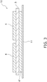
FIG. 3 is a cross-sectional view showing the configuration of a substrate sample for a semiconductor device according to an embodiment. - Hereinafter, the configuration of a ceramic sintered body according to the present invention and a substrate for a semiconductor device using the same will be described with reference to the drawings.
- (Structure of semiconductor device 1)
FIG. 1 is a cross-sectional view of a semiconductor device 1 according to the embodiment. The semiconductor device 1 is used as power module in various electronic devices such as an automobile, an air conditioner, an industrial robot, a commercial elevator, a household microwave oven, an IH electric rice cooker, power generation (wind power generation, solar power generation, fuel cell, or the like), electric railway, UPS (uninterruptible power supply) or the like. - The semiconductor device 1 includes a semiconductor device substrate 2, a first bonding material 5, a second bonding material 5', a
semiconductor chip 6, abonding wire 7, and aheat sink 8. - The semiconductor device substrate 2 is a so-called DBOC substrate (Direct Bonding of Copper Substrate). The semiconductor device substrate 2 includes a ceramic sintered
body 3, afirst copper plate 4, and asecond copper plate 4' . - The ceramic sintered
body 3 is an insulator for the semiconductor device substrate 2. The ceramic sinteredbody 3 is formed in a flat plate shape. The ceramic sinteredbody 3 is a substrate of the semiconductor device substrate 2. The configuration of the ceramic sinteredbody 3 will be described later. - The
first copper plate 4 is joined to the surface of the ceramic sinteredbody 3. A transmission circuit is formed on thefirst copper plate 4. Thesecond copper plate 4' is joined to the back surface of the ceramic sinteredbody 3. Thesecond copper plate 4' is formed in a flat plate shape. - Note that the semiconductor device substrate 2 may be a so-called DBOA substrate (Direct Bonding of Aluminum Substrate) using first and second aluminum plates instead of the first and
second copper plates - The method for manufacturing the semiconductor device substrate 2 is not particularly limited, and for example, it can be manufactured as follows. First, a laminate in which the first and
second copper plates body 3 is formed. Next, the laminate is heated for about 10 minutes under nitrogen atmosphere conditions of 1070 degrees C to 1075 degrees C. As a result, a Cu-O eutectic liquid phase is generated at the interface where the ceramic sinteredbody 3 and the first andsecond copper plates body 3 get wet. Next, the Cu-O eutectic liquid phase is solidified by cooling the laminate, and the first andsecond copper plates body 3. - The
first copper plate 4 on which a transmission circuit is formed is bonded to the surface of the ceramic sinteredbody 3 in the semiconductor device substrate 2. The transmission circuit may be formed by a subtractive method or an additive method. - The first bonding material 5 is arranged between the
first copper plate 4 and thesemiconductor chip 6. Thesemiconductor chip 6 is bonded to thefirst copper plate 4 via the first bonding material 5. Thebonding wire 7 connects thesemiconductor chip 6 and thefirst copper plate 4. - The second bonding material 5' is arranged between the
second copper plate 4' and theheat sink 8. Theheat sink 8 is bonded to thesecond copper plate 4' via the second bonding material 5'. Theheat sink 8 can be constituted of copper or the like, for example. - The ceramic
sintered body 3 includes at least one of Zr (zirconium), Hf (hafnium), Al (aluminum), Y (yttrium), Mg (magnesium), Si (silicon), Ca (calcium), at least one of Na (sodium) and K (potassium) , and the balance of other than these. - The contents of the constituent elements of the ceramic
sintered body 3 are as follows. - ·Zr: 17.5 mass% or more and 23.5 mass% or less in terms of ZrO2
- ·Hf: 0.3 mass% or more and 0.5 mass% or less in terms of HfO2
- ·Al: 74.3 mass% or more and 80.9 mass% or less in terms of Al2O3
- ·Y: 0.8 mass% or more and 1.9 mass% or less in terms of Y2O3
- ·Mg: 0.1 mass% or more and 0.8 mass% or less in terms of MgO
- ·Si: 0.1 mass% or more and 1.5 mass% or less in terms of SiO2
- ·Ca: 0.03 mass% or more and 0.35 mass% or less in terms of CaO
- ·Na and K: the total content is 0.01 mass% or more and 0.10 mass% or less, when the Na content is converted to Na2O and the K content is converted to K2O.
- ·Balance: 0.05 mass% or less in terms of oxide
- ·Additives: the sum of the Mg content in terms of MgO, the Si content in terms of SiO2, Ca content in terms of CaO, Na content in terms of Na2O, K content in terms of K2O, and the balance content is 0.3 mass% or more and 2.0 mass% or less.
- In this way, by optimizing the types and contents of the constituent elements of the ceramic
sintered body 3, the wettability with the Cu-O eutectic liquid phase at the time of copper plate bonding can be improved, so that at the time of copper plate bonding it is possible to prevent voids (partial peeling or floating) from occurring at the bonding interface and increase the mechanical strength of the ceramicsintered body 3. Therefore, even if the ceramicsintered body 3 is subjected to a thermal cycle, it is considered that it is possible to prevent cracks from occurring at the bonding interface. It is considered that such effects are produced by the combination of each constituent element including the content. Although the specific action is not clear, it is considered that the main actions and effects of each constituent element are as follows. - It is considered that by setting the Zr content to 17.5 mass% or more in terms of ZrO2, it is possible to prevent the linear thermal expansion coefficient of the ceramic
sintered body 3 from becoming too small, and reduce the difference in the coefficient of linear thermal expansion of the ceramicsintered body 3 and the first andsecond copper plates - It is considered that by setting the Zr content to 23.5 mass% or less in terms of ZrO2, it is possible to prevent an excessive reaction at the bonding interface at the time of copper plate bonding and prevent voids from occurring at the bonding interface. This is because the wettability of Al2O3 and ZrO2 with the Cu-O eutectic liquid phase at the time of copper plate bonding is different.
- It is considered that by setting the Hf content to 0.3 mass% or more in terms of HfO2, the heat resistance of the ceramic
sintered body 3 can be increased, so that it contributes to prevent pores from forming inside and prevent a decrease in the machine strength of the ceramicsintered body 3. - It is considered that by setting the Hf content to 0.5 mass% or less in terms of HfO2, the ceramic
sintered body 3 can be sintered without excessively raising the firing temperature, and the particle sizes of the Al2O3 particles and the ZrO2 particles are prevented from becoming large (that is, coarsening). As a result, it is considered that the mechanical strength of the ceramicsintered body 3 can be improved, so that it contributes to prevent cracks from occurring at the bonding interface. - It is considered that by setting the Y content to 0.8 mass% or more in terms of Y2O3, it is possible to prevent an excessive peak intensity ratio of the monoclinic crystal phase among the ZrO2 crystal phases described later. As a result, it is considered that the mechanical strength of the ceramic
sintered body 3 can be improved, so that it contributes to prevent cracks from occurring at the bonding interface. - It is considered that by setting the Y content to 1.9 mass% or less in terms of Y2O3, it is possible to prevent the peak intensity ratio of the monoclinic phase from becoming too small. As a result, it is considered that the mechanical strength of the ceramic
sintered body 3 can be improved, so that it contributes to prevent cracks from occurring at the bonding interface. - It is considered that by setting the Mg content to 0.1 mass% or more in terms of MgO, the ceramic
sintered body 3 can be sintered without excessively raising the firing temperature, and the coarsening of Al2O3 particles and ZrO2 particles is prevented. As a result, it is considered that the mechanical strength of the ceramicsintered body 3 can be improved, so that it contributes to prevent cracks from occurring at the bonding interface. Further, it is considered that a sufficient amount of MgAl2O4 crystals (hereinafter referred to as "spinel crystals") can be generated in the ceramicsintered body 3, and the wettability with the Cu-O eutectic liquid phase at the time of copper plate bonding can be improved. As a result, it is considered that it contributes to prevent voids from occurring at the bonding interface. - It is considered that by setting the Mg content to 0.8 mass% or less in terms of MgO, it is possible to prevent excessive formation of spinel crystals with low mechanical strength, so that it is possible to improve the mechanical strength of the ceramic
sintered body 3. As a result, it is considered that it contributes to prevent cracks from occurring at the bonding interface. - It is considered that by setting the Si content to 0.1 mass% or more in terms of SiO2, the ceramic
sintered body 3 can be sintered without excessively raising the firing temperature, and the coarsening of Al2O3 particles and ZrO2 particles is prevented. As a result, it is considered that the mechanical strength of the ceramicsintered body 3 can be improved, so that it contributes to prevent cracks from occurring at the bonding interface. - It is considered that by setting the Si content to 1.5 mass% or less in terms of SiO2, a spinel crystal phase is likely to be formed in the ceramic
sintered body 3, and the wettability with the Cu-O eutectic liquid phase at the time of copper plate bonding can be improved. As a result, it is considered that it contributes to prevent voids from occurring at the bonding interface. - It is considered that by setting the Ca content to 0.03 mass% or more and 0.35 mass% or less in terms of CaO, the ceramic
sintered body 3 can be sintered without excessively raising the firing temperature, and the coarsening of Al2O3 particles and ZrO2 particles can be prevented. As a result, it is considered that the mechanical strength of the ceramicsintered body 3 can be improved, so that it contributes to prevent cracks from occurring at the bonding interface. - It is considered that by setting the total content is 0.01 mass% or more when the Na content is converted to Na2O and the K content is converted to K2O, the ceramic
sintered body 3 can be sintered without an excessively high firing temperature, so that the coarsening of Al2O3 particles and ZrO2 particles can be prevented. As a result, it is considered that the mechanical strength of the ceramicsintered body 3 can be improved, so that it contributes to prevent cracks from occurring at the bonding interface. - It is considered that by setting the total content is 0.10 mass% or less when the Na content is converted to Na2O and the K content is converted to K2O, it is possible to prevent the
body 3 from being excessively sintered and reduce the porosity of the ceramicsintered body 3, although the firing temperature is not excessively raised. As a result, it is considered that the mechanical strength of the ceramicsintered body 3 can be improved, so that it contributes to prevent cracks from occurring at the bonding interface. - It is considered that by setting the content of the balance to 0.05 mass% or less in terms of oxide, it is possible to prevent the ceramic
sintered body 3 from being excessively sintered and reduce the porosity of the ceramicsintered body 3 although the firing temperature is not excessively raised. As a result, it is considered that the mechanical strength of the ceramicsintered body 3 can be improved, so that contributes to prevent cracks from occurring at the bonding interface. - It is considered that by setting the sum of the Mg content in terms of MgO, the Si content in terms of SiO2, the Ca content in terms of CaO, the Na content in terms of Na2O, the K content in terms of K2O, and the balance content to 0.3 mass% or more and 2.0 mass% or less, the M phase ratio described later can be put in a suitable range and the mechanical strength of the ceramic
sintered body 3 can be improved. As a result, it is considered that it contributes to prevent cracks from occurring at the bonding interface. - Although in the present embodiment, the content of the constituent elements of the ceramic
sintered body 3 is calculated in terms of oxide as described above, the constituent elements of the ceramicsintered body 3 may or may not exist in the form of oxide. For example, at least one of Y, Mg and Ca may not exist in the form of an oxide and may be dissolved in ZrO2. - Note that the content of the constituent elements of the ceramic
sintered body 3 in terms of oxide is calculated as follows. First, the constituent elements of the ceramicsintered body 3 are qualitatively analyzed using an energy dispersive analyzer (EDS) attached to a fluorescent X-ray analyzer (XRF) or a scanning electron microscope (SEM). Next, each element detected by this qualitative analysis is quantitatively analyzed using an ICP emission spectroscopic analyzer. Next, the content of each element measured by this quantitative analysis is converted into an oxide. - The element contained in the balance may be an element which is intentionally added or an element which is unavoidably mixed. The elements contained in the balance are not particularly limited, and examples thereof include Fe (iron), Ti (titanium), Mn (manganese) or the like.
- The ratio of the content of Y in terms of Y2O3 to the content of Zr in terms of ZrO2 is preferably 4.5% or more and 7.9% or less. As a result, the stability of ZrO2 can be maintained in an appropriate state, and it is considered that it contributes to prevent a decrease in the mechanical strength of the ceramic
sintered body 3. - The ceramic
sintered body 3 may include an Al2O3 crystal phase and a ZrO2 crystal phase as the crystal phase. The ZrO2 crystal phase may include a monoclinic phase and a tetragonal phase as a crystal structure. In this case, in the X-ray diffraction pattern, the ratio of the peak intensity of the monoclinic phase to the sum of the peak intensities of each of the monoclinic phase and the tetragonal phase (hereinafter referred to as "M phase ratio") is preferably 12% or less. As a result, the coarsening of Al2O3 particles and ZrO2 particles can be prevented. Further, since the phase transition from the monoclinic phase to the tetragonal phase is prevented when the ceramicsintered body 3 is heated, it is possible to prevent the volume shrinkage of the ceramicsintered body 3. As a result, since the mechanical strength of the ceramicsintered body 3 can be improved, it is possible to prevent cracks from occurring at the bonding interface even if the ceramicsintered body 3 is subjected to a thermal cycle. - The M phase ratio is more preferably 7 % or less. As a result, the mechanical strength of the ceramic
sintered body 3 can be further improved, so that it is possible to further prevent cracks from occurring at the bonding interface. - The M phase ratio can be obtained from the following formula (1) using an X-ray diffraction pattern obtained by analyzing the outer surface of the ceramic
sintered body 3 with an X-ray diffractometer (XRD: MiniFlexII manufactured by Rigaku Corporation). In the formula (1), M1 is the peak intensity of the monoclinic (111) plane, M2 is the peak intensity of the monoclinic (11-1) plane, T1 is the peak intensity of the tetragonal (111) plane, and T2 is the peak intensity of the cubic (111) plane.
- The ceramic
sintered body 3 may contain a spinel crystal phase as the crystal phase. In this case, in the X-ray diffraction pattern, the ratio of the peak intensity of MgAl2O4 to the peak intensity of Al2O3 (hereinafter referred to as "spinel phase ratio") is preferably 4% or less. As a result, it is possible to prevent an excessive reaction at the bonding interface at the time of copper plate bonding, so that it is possible to prevent voids from occurring at the bonding interface. Note that the spinel phase ratio may be 0%. - The spinel phase ratio is more preferably 0.5% or more and 3.5% or less. As a result, the wettability between the ceramic
sintered body 3 and the Cu-O eutectic liquid phase at the time of copper plate bonding can be improved, and the excessive reaction at the bonding interface at the time of copper plate bonding can be further prevented. It is possible to further prevent voids from occurring at the bonding interface. - The spinel phase ratio can be obtained from the following formula (2) using an X-ray diffraction pattern obtained by analyzing the surface of the ceramic
sintered body 3 with XRD. In the formula (2), A1 is the peak intensity of the spinel phase (311) plane, and B1 is the peak intensity of the alumina phase (104) plane.
- Although the average particle size of ZrO2 is not particularly limited, it is preferably 0.6 µm or more and 1.5 µm or less. As a result, it is possible to prevent an increase in the M phase ratio due to a decrease in the interfacial energy of the crystal transformation and a decrease in the mechanical strength accompanying the decrease, and it is possible to prevent pores from forming inside the ceramic
sintered body 3, so that it is possible to prevent a decrease in mechanical strength. - Although the average particle size of Al2O3 is not particularly limited, it is preferably 1.6 µm or more and 2.5 µm or less. By setting the average particle size of Al2O3 to 1.6 µm or more, it is possible to prevent pores from forming inside. By setting the average particle size of Al2O3 to 2.5 µm or less, the decrease of grain boundaries which become resistance to fracture strength can be prevented, the decrease in the mechanical strength of the ceramic
sintered body 3 can be prevented. - The average particle size of each of ZrO2 and Al2O3 is calculated as follows. First, when the outer surface of the ceramic
sintered body 3 is imaged with a scanning electron microscope, the magnification is adjusted so that about 500 to 1000 crystal particles are captured in the entire captured image. Next, using image processing software, the average circle-equivalent diameter of 100 crystal particles randomly selected from the captured image is calculated as the average particle size. The average circle-equivalent diameter is the average value of the circle-equivalent diameter, and the circle-equivalent diameter is the diameter of a circle including the same area as the particles. - With reference to
FIG. 2 , a method for manufacturing the ceramicsintered body 3 will be described.FIG. 2 is a flowchart showing a method for manufacturing the ceramicsintered body 3. - In step S1, the following powder materials are prepared.
- ·ZrO2 of 17.5 mass% or more and 23.5 mass% or less
- ·HfO2 of 0.3 mass% or more and 0.5 mass% or less
- ·Al2O3 of 74.3 mass% or more and 80.9 mass% or less
- ·Y2O3 of 0.8 mass% or more and 1.9 mass% or less
- ·MgO of 0.1 mass% or more and 0.8 mass% or less
- ·SiO2 of 0.1 mass% or more and 1.5 mass% or less
- ·CaO of 0.03 mass% or more and 0.35 mass% or less
- ·Na2O and K2O in total of 0.01 mass% or more and 0.10 mass% or less
- ·The balance of 0.05 mass% or less
- ·The sum of the Mg content in terms of MgO, the Si content in terms of SiO2, the Ca content in terms of CaO, the Na content in terms of Na2O, the K content in terms of K2O, and the balance content is 0.3 mass% or more and 2.0 mass% or less
- Note that each of ZrO2, HfO2, and Y2O3 may be a single powder material or may be ZrO2-HfO2 powder partially stabilized with Y2O3 in advance. Further, Mg, Ca, and alkali metals (Na and K) may be oxide powders or carbonate powders. When Fe and Mn are contained in the balance, these may be oxide powder or carbonate powder.
- In step S2, the prepared powder material is pulverized and mixed by, for example, a ball mill.
- In step S3, an organic binder (for example, polyvinyl butyral), a solvent (xylene, toluene, or the like) and a plasticizer (dioctyl phthalate) are added to the pulverized and mixed powder material to form a slurry-like substance.
- In step S4, the slurry-like substance is molded into a desired shape by a desired molding means (for example, mold press, cold hydrostatic press, injection molding, doctor blade method, extrusion molding method, or the like) to form a ceramic molded product.
- In step S5, the ceramic molded product is fired in an oxygen atmosphere or an air atmosphere (at 1580 degrees C to 1620 degrees C, 0.7 hours to 1.0 hours).
- As illustrated in
FIG. 3 , when thesubstrate samples 10 for semiconductor devices according to Examples 1 to 19 and Comparative Examples 1 to 17 are produced, and we observed voids generated at the bonding interface when the copper plates are bonded and cracks generated at the bonding interface when subjected to a thermal cycle. - First, the powder material prepared with the compositions illustrated in Table 1 was pulverized and mixed by a ball mill.
- Next, polyvinyl butyral as an organic binder, xylene as a solvent, and dioctyl phthalate as a plasticizer were added to the pulverized and mixed powder material to form a slurry-like substance.
- Next, a ceramic molded body was produced by molding a slurry-like substance into a sheet by the doctor blade method.
- Next, the ceramic molded product was fired in an air atmosphere at the firing temperature illustrated in Table 1 for 0. 8 hours to prepare a ceramic
sintered body 3. The size of the ceramicsintered body 3 was 0.32 mm in thickness, 39 mm in length, and 45 mm in width. - Next, the first and
second copper plates second copper plates - Next, a laminate in which the ceramic
sintered body 3 is sandwiched between the first andsecond copper plates mesh material 11 constituted of Mo (molybdenum) and heated at 1070 degrees C in a nitrogen (N2) atmosphere for 10 minutes. - Next, by cooling the laminate, the first and
second copper plates sintered body 3, and themesh material 11 was joined to thesecond copper plate 4'. - From the above formula (1), the M phase ratio was calculated using the X-ray diffraction pattern obtained by analyzing the outer surface of the ceramic
sintered body 3 according to Examples 1 to 19 and Comparative Examples 1 to 17 with XRD (MiniFlexII manufactured by Rigaku Corporation). The calculated M phase ratios are summarized in Table 1. - From the above formula (2), the spinel phase ratio was calculated using the X-ray diffraction pattern obtained by analyzing the outer surface of the ceramic
sintered body 3 according to Examples 1 to 19 and Comparative Examples 1 to 17 with XRD (MiniFlexII manufactured by Rigaku Corporation). The calculated spinel phase ratios are summarized in Table 1. - The flexural strength (mechanical strength) of the ceramic
sintered body 3 according to Examples 1 to 19 and Comparative Examples 1 to 17 was measured by three-point bending strength test (sample size 15 x 45 x thickness 0.32 mm and span 30 mm) . - In Table 1, for Examples 1 to 19 and Comparative Examples 1 to 17, the arithmetic mean value of the measured values of 10 pieces each is described as the flexural strength (MPa).
-
Substrate samples 10 for semiconductor devices according to Examples 1 to 19 and Comparative Examples 1 to 17 are immersed in water, and the bonding interface between the ceramicsintered body 3 and the first andsecond copper plates - In Table 1, for Examples 1 to 19 and Comparative Examples 1 to 17, the percentage of 100 pieces in which voids are observed is illustrated as a void occurrence rate (%). In Table 1, samples including a void occurrence rate (%) of less than 0.2 are evaluated as "⊚", samples of 0.2 or more and less than 0.3 are evaluated as "○", and samples of 0.3 or more and less than 0.5 are evaluated as "Δ", and samples of 0.5 or more are evaluated as "x".
- Regarding the semiconductor
device substrate samples 10 according to Examples 1 to 19 and Comparative Examples 1 to 17, the cycle of "first at -40 degrees C for 30 minutes, secondly at 25 degrees C for 5 minutes, thirdly at 125 degrees C for 30 minutes, and finally at 25 degrees C for 5 minutes" was repeated until cracks occurred in the ceramicsintered body 3. - In Table 1, for Examples 1 to 19 and Comparative Examples 1 to 17, the number of cycles in which cracks occur in any of the 10 pieces is listed as the number of crack generation cycles. In Table 1, samples with crack occurrence cycles (times) of 101 or more are evaluated as "⊚", samples with 51 or more and 100 or less are evaluated as "○", and samples with 31 or more and 50 or less are evaluated as "Δ", and 30 or less samples are evaluated as "x".

- As illustrated in Table 1, in Examples 1 to 19 in which the content of the constituent elements in the ceramic
sintered body 3 was optimized as follows, voids at the bonding interface could be prevented and cracks could be prevented from occurring at the bonding interface. - ·Zr: 17.5 mass% or more and 23.5 mass% or less in terms of ZrO2
- ·Hf: 0.3 mass% or more and 0.5 mass% or less in terms of HfO2
- ·Al: 74.3 mass% or more and 80.9 mass% or less in terms of Al2O3
- ·Y: 0.8 mass% or more and 1.9 mass% or less in terms of Y2O3
- ·Mg: 0.1 mass% or more and 0.8 mass% or less in terms of MgO
- ·Si: 0.1 mass% or more and 1.5 mass% or less in terms of SiO2
- ·Ca: 0.03 mass% or more and 0.35 mass% or less in terms of CaO
- ·Na and K: When the Na content is converted to Na2O and the K content is converted to K2O, the total content is 0.01 mass% or more and 0.10 mass% or less.
- ·Balance: 0.05 mass% or less in terms of oxide
- ·Additives: The sum of the Mg content in terms of MgO, the Si content in terms of SiO2, the Ca content in terms of CaO, the Na content in terms of Na2O, the K content in terms of K2O, and the balance content is 0.3 mass% or more and 2.0 mass% or less.
- According to the present invention, since cracks and voids in the ceramic sintered body can be prevented, the ceramic sintered body and the substrate for a semiconductor device according to the present invention can be used in various electronic devices.
-
- 1
- Semiconductor device
- 2
- Substrate for semiconductor device
- 3
- Ceramic sintered body
- 4, 4'
- Copper plate
- 5, 5'
- Joining material
- 6
- Semiconductor chip
- 7
- Bonding wire
- 8
- Heat sink
- 10
- Substrate sample for semiconductor device
- 11
- Mesh material
Claims (9)
- A ceramic sintered body joined to a copper plate or an aluminum plate, wherein
a Zr content is 17.5 mass% or more and 23.5 mass% or less in terms of ZrO2,
an Hf content is 0.3 mass% or more and 0.5 mass% or less in terms of HfO2,
an Al content is 74.3 mass% or more and 80.9 mass% or less in terms of Al2O3,
a Y content is 0.8 mass% or more and 1.9 mass% or less in terms of Y2O3,
an Mg content is 0.1 mass% or more and 0.8 mass% or less in terms of MgO,
a Si content is 0.1 mass% or more and 1.5 mass% or less in terms of SiO2,
a Ca content is 0.03 mass% or more and 0.35 mass% or less in terms of CaO,
a total content of Na and K is 0.01 mass% or more and 0.10 mass% or less when the Na content is converted to Na2O and the K content is converted to K2O,
a balance content is 0.05 mass% or less in terms of oxide, and
a sum of the Mg content in terms of MgO, the Si content in terms of SiO2, the Ca content in terms of CaO, the Na content in terms of Na2O, the K content in terms of K2O, and the balance content is 0.3 mass% or more and 2.0 mass% or less. - The ceramic sintered body according to claim 1 containing an Al2O3 crystal phase and a ZrO2 crystal phase as crystal phases, wherein
the ZrO2 crystal phase contains a monoclinic phase and a tetragonal phase as crystal structures,
a ratio of a peak intensity of the monoclinic phase to a sum of the peak intensity of the monoclinic phase and a peak intensity of the tetragonal phase is 12% or less in a X-ray diffraction pattern. - The ceramic sintered body according to claim 1 containing an Al2O3 crystal phase and a ZrO2 crystal phase as crystal phases, wherein
the ZrO2 crystal phase contains a monoclinic phase and a tetragonal phase as crystal structures,
a ratio of a peak intensity of the monoclinic phase to a sum of the peak intensity of the monoclinic phase and a peak intensity of the tetragonal phase is 7% or less in a X-ray diffraction pattern. - The ceramic sintered body according to any one of claims 1 to 3 containing MgAl2O4 crystal phase as a crystal phase, wherein
a ratio of a peak intensity of MgAl2O4 to a peak intensity of Al2O3 is 4% or less in a X-ray diffraction pattern. - The ceramic sintered body according to any one of claims 1 to 3 containing MgAl2O4 crystal phase as a crystal phase, wherein
a ratio of a peak intensity of MgAl2O4 to a peak intensity of Al2O3 is 0.5% or more and 3.5% or less in a X-ray diffraction pattern. - The ceramic sintered body according to any one of claims 1 to 5, wherein
an average particle size of ZrO2 is 0.6 µm or more and 1.5 µm or less. - The ceramic sintered body according to any one of claims 1 to 6, wherein
an average particle size of Al2O3 is 1.6 µm or more and 2.5 µm or less. - The ceramic sintered body according to any one of claims 1 to 7, wherein
a ratio of the Y content in terms of Y2O3 to the Zr content in terms of ZrO2 is 4.5% or more and 7.9% or less. - A substrate for a semiconductor device on which electronic components mounted, the substrate comprising:a ceramic sintered body; anda copper plate or an aluminum plate joined to the ceramic sintered body, whereinin the ceramic sintered body,a Zr content is 17.5 mass% or more and 23.5 mass% or less in terms of ZrO2,an Hf content is 0.3 mass% or more and 0.5 mass% or less in terms of HfO2,an Al content is 74.3 mass% or more and 80.9 mass% or less in terms of Al2O3,a Y content is 0.8 mass% or more and 1.9 mass% or less in terms of Y2O3,an Mg content is 0.1 mass% or more and 0.8 mass% or less in terms of MgO,an Si content is 0.1 mass% or more and 1.5 mass% or less in terms of SiO2,a Ca content is 0.03 mass% or more and 0.35 mass% or less in terms of CaO,a total content of Na and K is 0.01 mass% or more and 0.10 mass% or less when the Na content is converted to Na2O and the K content is converted to K2O,a balance content is 0.05 mass% or less in terms of oxide, anda sum of the Mg content in terms of MgO, the Si content in terms of SiO2, the Ca content in terms of CaO, the Na content in terms of Na2O, the K content in terms of K2O, and the balance content is 0.3 mass% or more and 2.0 mass% or less.
Applications Claiming Priority (1)
| Application Number | Priority Date | Filing Date | Title |
|---|---|---|---|
| PCT/JP2018/044942 WO2020115868A1 (en) | 2018-12-06 | 2018-12-06 | Ceramic sintered body and substrate for semiconductor device |
Publications (3)
| Publication Number | Publication Date |
|---|---|
| EP3854766A1 true EP3854766A1 (en) | 2021-07-28 |
| EP3854766A4 EP3854766A4 (en) | 2022-05-11 |
| EP3854766B1 EP3854766B1 (en) | 2025-12-17 |
Family
ID=70974928
Family Applications (1)
| Application Number | Title | Priority Date | Filing Date |
|---|---|---|---|
| EP18942212.4A Active EP3854766B1 (en) | 2018-12-06 | 2018-12-06 | Ceramic sintered body and substrate for semiconductor device |
Country Status (5)
| Country | Link |
|---|---|
| US (1) | US11897817B2 (en) |
| EP (1) | EP3854766B1 (en) |
| JP (1) | JP7062087B2 (en) |
| CN (1) | CN112789256B (en) |
| WO (1) | WO2020115868A1 (en) |
Cited By (1)
| Publication number | Priority date | Publication date | Assignee | Title |
|---|---|---|---|---|
| EP4653406A1 (en) * | 2024-05-21 | 2025-11-26 | CeramTec GmbH | Ceramic substrate |
Families Citing this family (7)
| Publication number | Priority date | Publication date | Assignee | Title |
|---|---|---|---|---|
| JP7251001B2 (en) * | 2020-12-04 | 2023-04-03 | Ngkエレクトロデバイス株式会社 | Ceramic sintered bodies and substrates for semiconductor devices |
| WO2022208900A1 (en) * | 2021-03-29 | 2022-10-06 | Ngkエレクトロデバイス株式会社 | Ceramic sintered body and substrate for semiconductor device |
| JP7589807B2 (en) * | 2021-04-28 | 2024-11-26 | 富士電機株式会社 | Semiconductor Device |
| JP7802091B2 (en) * | 2021-11-12 | 2026-01-19 | 京セラ株式会社 | Sliding member and false twisting machine disc using same |
| EP4242192A1 (en) | 2022-03-11 | 2023-09-13 | CeramTec GmbH | Ceramic substrate |
| WO2024053619A1 (en) * | 2022-09-05 | 2024-03-14 | Ngkエレクトロデバイス株式会社 | Ceramic substrate, and semiconductor device substrate provided with same |
| WO2024071385A1 (en) * | 2022-09-29 | 2024-04-04 | 京セラ株式会社 | Composite ceramic |
Family Cites Families (14)
| Publication number | Priority date | Publication date | Assignee | Title |
|---|---|---|---|---|
| US4285732A (en) * | 1980-03-11 | 1981-08-25 | General Electric Company | Alumina ceramic |
| JP3076682B2 (en) * | 1992-09-25 | 2000-08-14 | 東芝タンガロイ株式会社 | Alumina-based sintered body and method for producing the same |
| US8614542B2 (en) * | 2006-12-18 | 2013-12-24 | Federal-Mogul Ignition Company | Alumina ceramic for spark plug insulator |
| WO2010114126A1 (en) * | 2009-04-03 | 2010-10-07 | 株式会社住友金属エレクトロデバイス | Sintered ceramic and substrate comprising same for semiconductor device |
| EP2637204B8 (en) * | 2010-11-01 | 2017-05-31 | Nippon Steel & Sumikin Electronics Devices Inc. | An electronic component element housing package |
| WO2013008919A1 (en) * | 2011-07-14 | 2013-01-17 | 株式会社東芝 | Ceramic circuit board |
| SG188775A1 (en) * | 2011-09-30 | 2013-04-30 | Hoya Corp | Manufacturing method of glass substrate for magnetic disk, magnetic disk, and magnetic data recording/reproducing device |
| JP5836862B2 (en) * | 2012-03-26 | 2015-12-24 | 京セラ株式会社 | Electronic component mounting substrate and electronic device |
| DE102012110322B4 (en) * | 2012-10-29 | 2014-09-11 | Rogers Germany Gmbh | Metal-ceramic substrate and method for producing a metal-ceramic substrate |
| JP2016041632A (en) * | 2012-12-25 | 2016-03-31 | ニッコー株式会社 | Alumina substrate and substrate for semiconductor device |
| JP6038698B2 (en) * | 2013-03-22 | 2016-12-07 | 日本碍子株式会社 | Ceramic member and member for semiconductor manufacturing equipment |
| FR3008967B1 (en) | 2013-07-26 | 2016-12-30 | Saint-Gobain Centre De Rech Et D'Etudes Europeen | HIGH ALUMINUM PRODUCT |
| EP3315476B1 (en) | 2015-06-26 | 2020-02-26 | Kyocera Corporation | Ceramic substrate and mounting substrate using same, and electronic device |
| JP6314292B1 (en) * | 2016-06-16 | 2018-04-18 | 日本碍子株式会社 | Ceramic substrate and manufacturing method thereof |
-
2018
- 2018-12-06 EP EP18942212.4A patent/EP3854766B1/en active Active
- 2018-12-06 CN CN201880098397.9A patent/CN112789256B/en active Active
- 2018-12-06 WO PCT/JP2018/044942 patent/WO2020115868A1/en not_active Ceased
- 2018-12-06 JP JP2020558756A patent/JP7062087B2/en active Active
-
2021
- 2021-05-12 US US17/317,986 patent/US11897817B2/en active Active
Cited By (2)
| Publication number | Priority date | Publication date | Assignee | Title |
|---|---|---|---|---|
| EP4653406A1 (en) * | 2024-05-21 | 2025-11-26 | CeramTec GmbH | Ceramic substrate |
| WO2025242563A1 (en) * | 2024-05-21 | 2025-11-27 | Ceramtec Gmbh | Ceramic substrate |
Also Published As
| Publication number | Publication date |
|---|---|
| EP3854766A4 (en) | 2022-05-11 |
| US20210261473A1 (en) | 2021-08-26 |
| WO2020115868A1 (en) | 2020-06-11 |
| EP3854766B1 (en) | 2025-12-17 |
| CN112789256B (en) | 2022-11-08 |
| US11897817B2 (en) | 2024-02-13 |
| JPWO2020115868A1 (en) | 2021-09-30 |
| CN112789256A (en) | 2021-05-11 |
| JP7062087B2 (en) | 2022-05-02 |
Similar Documents
| Publication | Publication Date | Title |
|---|---|---|
| EP3854766B1 (en) | Ceramic sintered body and substrate for semiconductor device | |
| JP6591455B2 (en) | High thermal conductivity silicon nitride sintered body, silicon nitride substrate, silicon nitride circuit substrate and semiconductor device using the same | |
| JP5559590B2 (en) | Ceramic sintered body, method for producing the same, and ceramic structure | |
| US20210246072A1 (en) | Ceramic sintered body and substrate for semiconductor devices | |
| WO2020027077A1 (en) | Silicon nitride sintered body, silicon nitride substrate, and silicon nitride circuit substrate | |
| WO2024053619A1 (en) | Ceramic substrate, and semiconductor device substrate provided with same | |
| JP7251001B2 (en) | Ceramic sintered bodies and substrates for semiconductor devices | |
| EP3855484B1 (en) | Substrate for semiconductor device | |
| JPH11100274A (en) | Silicon nitride sintered compact, its production and circuit board | |
| JP2025084166A (en) | Silicon nitride sintered body and silicon nitride heat dissipation substrate | |
| WO2022208900A1 (en) | Ceramic sintered body and substrate for semiconductor device | |
| JP7148613B2 (en) | Alumina porcelain and ceramic heater | |
| JP7849573B1 (en) | Ceramic substrate, and semiconductor device substrate equipped therewith | |
| JPH11100273A (en) | Silicon nitride sintered compact, its production and circuit board | |
| WO2024069888A1 (en) | Substrate for semiconductor device and method for producing same | |
| JPH11322437A (en) | Silicon nitride sintered body, method of manufacturing the same, and circuit board using the same | |
| JP2025115138A (en) | Silicon nitride sintered body and silicon nitride heat dissipation substrate | |
| JP2021034633A (en) | Method for manufacturing ceramic circuit board | |
| JPH0987031A (en) | Low temperature sintered aluminum nitride sintered body and semiconductor package using the same |
Legal Events
| Date | Code | Title | Description |
|---|---|---|---|
| STAA | Information on the status of an ep patent application or granted ep patent |
Free format text: STATUS: THE INTERNATIONAL PUBLICATION HAS BEEN MADE |
|
| PUAI | Public reference made under article 153(3) epc to a published international application that has entered the european phase |
Free format text: ORIGINAL CODE: 0009012 |
|
| STAA | Information on the status of an ep patent application or granted ep patent |
Free format text: STATUS: REQUEST FOR EXAMINATION WAS MADE |
|
| 17P | Request for examination filed |
Effective date: 20210422 |
|
| AK | Designated contracting states |
Kind code of ref document: A1 Designated state(s): AL AT BE BG CH CY CZ DE DK EE ES FI FR GB GR HR HU IE IS IT LI LT LU LV MC MK MT NL NO PL PT RO RS SE SI SK SM TR |
|
| DAV | Request for validation of the european patent (deleted) | ||
| DAX | Request for extension of the european patent (deleted) | ||
| A4 | Supplementary search report drawn up and despatched |
Effective date: 20220411 |
|
| RIC1 | Information provided on ipc code assigned before grant |
Ipc: C04B 37/02 20060101ALI20220406BHEP Ipc: C04B 35/119 20060101AFI20220406BHEP |
|
| GRAP | Despatch of communication of intention to grant a patent |
Free format text: ORIGINAL CODE: EPIDOSNIGR1 |
|
| STAA | Information on the status of an ep patent application or granted ep patent |
Free format text: STATUS: GRANT OF PATENT IS INTENDED |
|
| RIC1 | Information provided on ipc code assigned before grant |
Ipc: C04B 35/119 20060101AFI20250623BHEP Ipc: C04B 37/02 20060101ALI20250623BHEP |
|
| INTG | Intention to grant announced |
Effective date: 20250707 |
|
| GRAS | Grant fee paid |
Free format text: ORIGINAL CODE: EPIDOSNIGR3 |
|
| GRAA | (expected) grant |
Free format text: ORIGINAL CODE: 0009210 |
|
| STAA | Information on the status of an ep patent application or granted ep patent |
Free format text: STATUS: THE PATENT HAS BEEN GRANTED |
|
| AK | Designated contracting states |
Kind code of ref document: B1 Designated state(s): AL AT BE BG CH CY CZ DE DK EE ES FI FR GB GR HR HU IE IS IT LI LT LU LV MC MK MT NL NO PL PT RO RS SE SI SK SM TR |
|
| REG | Reference to a national code |
Ref country code: CH Ref legal event code: F10 Free format text: ST27 STATUS EVENT CODE: U-0-0-F10-F00 (AS PROVIDED BY THE NATIONAL OFFICE) Effective date: 20251217 Ref country code: GB Ref legal event code: FG4D |
|
| REG | Reference to a national code |
Ref country code: DE Ref legal event code: R096 Ref document number: 602018088055 Country of ref document: DE |
|
| REG | Reference to a national code |
Ref country code: LT Ref legal event code: MG9D |
|
| PG25 | Lapsed in a contracting state [announced via postgrant information from national office to epo] |
Ref country code: NO Free format text: LAPSE BECAUSE OF FAILURE TO SUBMIT A TRANSLATION OF THE DESCRIPTION OR TO PAY THE FEE WITHIN THE PRESCRIBED TIME-LIMIT Effective date: 20260317 |
|
| PG25 | Lapsed in a contracting state [announced via postgrant information from national office to epo] |
Ref country code: FI Free format text: LAPSE BECAUSE OF FAILURE TO SUBMIT A TRANSLATION OF THE DESCRIPTION OR TO PAY THE FEE WITHIN THE PRESCRIBED TIME-LIMIT Effective date: 20251217 Ref country code: HR Free format text: LAPSE BECAUSE OF FAILURE TO SUBMIT A TRANSLATION OF THE DESCRIPTION OR TO PAY THE FEE WITHIN THE PRESCRIBED TIME-LIMIT Effective date: 20251217 |
|
| PG25 | Lapsed in a contracting state [announced via postgrant information from national office to epo] |
Ref country code: RS Free format text: LAPSE BECAUSE OF FAILURE TO SUBMIT A TRANSLATION OF THE DESCRIPTION OR TO PAY THE FEE WITHIN THE PRESCRIBED TIME-LIMIT Effective date: 20260317 |
|
| REG | Reference to a national code |
Ref country code: NL Ref legal event code: MP Effective date: 20251217 |
|
| PG25 | Lapsed in a contracting state [announced via postgrant information from national office to epo] |
Ref country code: LV Free format text: LAPSE BECAUSE OF FAILURE TO SUBMIT A TRANSLATION OF THE DESCRIPTION OR TO PAY THE FEE WITHIN THE PRESCRIBED TIME-LIMIT Effective date: 20251217 |
|
| PG25 | Lapsed in a contracting state [announced via postgrant information from national office to epo] |
Ref country code: BG Free format text: LAPSE BECAUSE OF FAILURE TO SUBMIT A TRANSLATION OF THE DESCRIPTION OR TO PAY THE FEE WITHIN THE PRESCRIBED TIME-LIMIT Effective date: 20251217 |
|
| REG | Reference to a national code |
Ref country code: AT Ref legal event code: MK05 Ref document number: 1868400 Country of ref document: AT Kind code of ref document: T Effective date: 20251217 |
|
| PG25 | Lapsed in a contracting state [announced via postgrant information from national office to epo] |
Ref country code: NL Free format text: LAPSE BECAUSE OF FAILURE TO SUBMIT A TRANSLATION OF THE DESCRIPTION OR TO PAY THE FEE WITHIN THE PRESCRIBED TIME-LIMIT Effective date: 20251217 |
|
| PG25 | Lapsed in a contracting state [announced via postgrant information from national office to epo] |
Ref country code: LT Free format text: LAPSE BECAUSE OF FAILURE TO SUBMIT A TRANSLATION OF THE DESCRIPTION OR TO PAY THE FEE WITHIN THE PRESCRIBED TIME-LIMIT Effective date: 20251217 |
|
| PG25 | Lapsed in a contracting state [announced via postgrant information from national office to epo] |
Ref country code: SM Free format text: LAPSE BECAUSE OF FAILURE TO SUBMIT A TRANSLATION OF THE DESCRIPTION OR TO PAY THE FEE WITHIN THE PRESCRIBED TIME-LIMIT Effective date: 20251217 |
|
| PG25 | Lapsed in a contracting state [announced via postgrant information from national office to epo] |
Ref country code: ES Free format text: LAPSE BECAUSE OF FAILURE TO SUBMIT A TRANSLATION OF THE DESCRIPTION OR TO PAY THE FEE WITHIN THE PRESCRIBED TIME-LIMIT Effective date: 20251217 |
|
| PG25 | Lapsed in a contracting state [announced via postgrant information from national office to epo] |
Ref country code: PL Free format text: LAPSE BECAUSE OF FAILURE TO SUBMIT A TRANSLATION OF THE DESCRIPTION OR TO PAY THE FEE WITHIN THE PRESCRIBED TIME-LIMIT Effective date: 20251217 |
|
| PG25 | Lapsed in a contracting state [announced via postgrant information from national office to epo] |
Ref country code: IT Free format text: LAPSE BECAUSE OF FAILURE TO SUBMIT A TRANSLATION OF THE DESCRIPTION OR TO PAY THE FEE WITHIN THE PRESCRIBED TIME-LIMIT Effective date: 20251217 |
|
| PG25 | Lapsed in a contracting state [announced via postgrant information from national office to epo] |
Ref country code: AT Free format text: LAPSE BECAUSE OF FAILURE TO SUBMIT A TRANSLATION OF THE DESCRIPTION OR TO PAY THE FEE WITHIN THE PRESCRIBED TIME-LIMIT Effective date: 20251217 |
|
| PG25 | Lapsed in a contracting state [announced via postgrant information from national office to epo] |
Ref country code: EE Free format text: LAPSE BECAUSE OF FAILURE TO SUBMIT A TRANSLATION OF THE DESCRIPTION OR TO PAY THE FEE WITHIN THE PRESCRIBED TIME-LIMIT Effective date: 20251217 |
|
| PG25 | Lapsed in a contracting state [announced via postgrant information from national office to epo] |
Ref country code: PT Free format text: LAPSE BECAUSE OF FAILURE TO SUBMIT A TRANSLATION OF THE DESCRIPTION OR TO PAY THE FEE WITHIN THE PRESCRIBED TIME-LIMIT Effective date: 20260417 Ref country code: IS Free format text: LAPSE BECAUSE OF FAILURE TO SUBMIT A TRANSLATION OF THE DESCRIPTION OR TO PAY THE FEE WITHIN THE PRESCRIBED TIME-LIMIT Effective date: 20260417 |
|
| PG25 | Lapsed in a contracting state [announced via postgrant information from national office to epo] |
Ref country code: CZ Free format text: LAPSE BECAUSE OF FAILURE TO SUBMIT A TRANSLATION OF THE DESCRIPTION OR TO PAY THE FEE WITHIN THE PRESCRIBED TIME-LIMIT Effective date: 20251217 |
|
| PG25 | Lapsed in a contracting state [announced via postgrant information from national office to epo] |
Ref country code: SK Free format text: LAPSE BECAUSE OF FAILURE TO SUBMIT A TRANSLATION OF THE DESCRIPTION OR TO PAY THE FEE WITHIN THE PRESCRIBED TIME-LIMIT Effective date: 20251217 |
|
| PG25 | Lapsed in a contracting state [announced via postgrant information from national office to epo] |
Ref country code: SE Free format text: LAPSE BECAUSE OF FAILURE TO SUBMIT A TRANSLATION OF THE DESCRIPTION OR TO PAY THE FEE WITHIN THE PRESCRIBED TIME-LIMIT Effective date: 20251217 |