EP3854698A1 - Orientation control device, satellite, orientation control method, and program - Google Patents
Orientation control device, satellite, orientation control method, and program Download PDFInfo
- Publication number
- EP3854698A1 EP3854698A1 EP19863349.7A EP19863349A EP3854698A1 EP 3854698 A1 EP3854698 A1 EP 3854698A1 EP 19863349 A EP19863349 A EP 19863349A EP 3854698 A1 EP3854698 A1 EP 3854698A1
- Authority
- EP
- European Patent Office
- Prior art keywords
- attitude
- ideal
- satellite
- target
- calculator
- Prior art date
- Legal status (The legal status is an assumption and is not a legal conclusion. Google has not performed a legal analysis and makes no representation as to the accuracy of the status listed.)
- Granted
Links
Images



Classifications
-
- B—PERFORMING OPERATIONS; TRANSPORTING
- B64—AIRCRAFT; AVIATION; COSMONAUTICS
- B64G—COSMONAUTICS; VEHICLES OR EQUIPMENT THEREFOR
- B64G1/00—Cosmonautic vehicles
- B64G1/22—Parts of, or equipment specially adapted for fitting in or to, cosmonautic vehicles
- B64G1/24—Guiding or controlling apparatus, e.g. for attitude control
- B64G1/244—Spacecraft control systems
-
- B—PERFORMING OPERATIONS; TRANSPORTING
- B64—AIRCRAFT; AVIATION; COSMONAUTICS
- B64G—COSMONAUTICS; VEHICLES OR EQUIPMENT THEREFOR
- B64G1/00—Cosmonautic vehicles
- B64G1/22—Parts of, or equipment specially adapted for fitting in or to, cosmonautic vehicles
- B64G1/24—Guiding or controlling apparatus, e.g. for attitude control
- B64G1/242—Orbits and trajectories
- B64G1/2427—Transfer orbits
-
- B—PERFORMING OPERATIONS; TRANSPORTING
- B64—AIRCRAFT; AVIATION; COSMONAUTICS
- B64G—COSMONAUTICS; VEHICLES OR EQUIPMENT THEREFOR
- B64G1/00—Cosmonautic vehicles
- B64G1/22—Parts of, or equipment specially adapted for fitting in or to, cosmonautic vehicles
- B64G1/24—Guiding or controlling apparatus, e.g. for attitude control
- B64G1/244—Spacecraft control systems
- B64G1/245—Attitude control algorithms for spacecraft attitude control
-
- B—PERFORMING OPERATIONS; TRANSPORTING
- B64—AIRCRAFT; AVIATION; COSMONAUTICS
- B64G—COSMONAUTICS; VEHICLES OR EQUIPMENT THEREFOR
- B64G1/00—Cosmonautic vehicles
- B64G1/22—Parts of, or equipment specially adapted for fitting in or to, cosmonautic vehicles
- B64G1/24—Guiding or controlling apparatus, e.g. for attitude control
- B64G1/26—Guiding or controlling apparatus, e.g. for attitude control using jets
-
- B—PERFORMING OPERATIONS; TRANSPORTING
- B64—AIRCRAFT; AVIATION; COSMONAUTICS
- B64G—COSMONAUTICS; VEHICLES OR EQUIPMENT THEREFOR
- B64G1/00—Cosmonautic vehicles
- B64G1/22—Parts of, or equipment specially adapted for fitting in or to, cosmonautic vehicles
- B64G1/24—Guiding or controlling apparatus, e.g. for attitude control
- B64G1/28—Guiding or controlling apparatus, e.g. for attitude control using inertia or gyro effect
- B64G1/283—Guiding or controlling apparatus, e.g. for attitude control using inertia or gyro effect using reaction wheels
-
- B—PERFORMING OPERATIONS; TRANSPORTING
- B64—AIRCRAFT; AVIATION; COSMONAUTICS
- B64G—COSMONAUTICS; VEHICLES OR EQUIPMENT THEREFOR
- B64G1/00—Cosmonautic vehicles
- B64G1/22—Parts of, or equipment specially adapted for fitting in or to, cosmonautic vehicles
- B64G1/24—Guiding or controlling apparatus, e.g. for attitude control
- B64G1/28—Guiding or controlling apparatus, e.g. for attitude control using inertia or gyro effect
- B64G1/286—Guiding or controlling apparatus, e.g. for attitude control using inertia or gyro effect using control momentum gyroscopes (CMGs)
-
- B—PERFORMING OPERATIONS; TRANSPORTING
- B64—AIRCRAFT; AVIATION; COSMONAUTICS
- B64G—COSMONAUTICS; VEHICLES OR EQUIPMENT THEREFOR
- B64G1/00—Cosmonautic vehicles
- B64G1/22—Parts of, or equipment specially adapted for fitting in or to, cosmonautic vehicles
- B64G1/42—Arrangements or adaptations of power supply systems
- B64G1/44—Arrangements or adaptations of power supply systems using radiation, e.g. deployable solar arrays
-
- B—PERFORMING OPERATIONS; TRANSPORTING
- B64—AIRCRAFT; AVIATION; COSMONAUTICS
- B64G—COSMONAUTICS; VEHICLES OR EQUIPMENT THEREFOR
- B64G1/00—Cosmonautic vehicles
- B64G1/22—Parts of, or equipment specially adapted for fitting in or to, cosmonautic vehicles
- B64G1/42—Arrangements or adaptations of power supply systems
- B64G1/44—Arrangements or adaptations of power supply systems using radiation, e.g. deployable solar arrays
- B64G1/443—Photovoltaic cell arrays
-
- B—PERFORMING OPERATIONS; TRANSPORTING
- B64—AIRCRAFT; AVIATION; COSMONAUTICS
- B64G—COSMONAUTICS; VEHICLES OR EQUIPMENT THEREFOR
- B64G1/00—Cosmonautic vehicles
- B64G1/22—Parts of, or equipment specially adapted for fitting in or to, cosmonautic vehicles
- B64G1/24—Guiding or controlling apparatus, e.g. for attitude control
- B64G1/244—Spacecraft control systems
- B64G1/247—Advanced control concepts for autonomous, robotic spacecraft, e.g. by using artificial intelligence, neural networks or autonomous agents
-
- B—PERFORMING OPERATIONS; TRANSPORTING
- B64—AIRCRAFT; AVIATION; COSMONAUTICS
- B64G—COSMONAUTICS; VEHICLES OR EQUIPMENT THEREFOR
- B64G1/00—Cosmonautic vehicles
- B64G1/22—Parts of, or equipment specially adapted for fitting in or to, cosmonautic vehicles
- B64G1/40—Arrangements or adaptations of propulsion systems
Definitions
- the present invention relates to an attitude control apparatus for controlling the attitude of a satellite, a satellite, a method of controlling attitude, and a program.
- a geostationary satellite is separated from a rocket and introduced into an orbit, such as low earth orbit (LEO), geostationary transfer orbit (GTO), or super synchronous orbit (SSO).
- LEO low earth orbit
- GTO geostationary transfer orbit
- SSO super synchronous orbit
- the geostationary satellite then causes firing of a thruster mounted thereon and thus obtains a thrust, thereby shifting from the initial orbit, into which the geostationary satellite has been introduced, to the geostationary earth orbit (GEO).
- the thruster include a chemical thruster and an electric propulsion thruster.
- the chemical thruster can generate a greater thrust, and therefore requires a shorter time for orbit transfer from the GTO to the GEO but requires a higher propellant consumption, in comparison to the electric propulsion thruster.
- the electric propulsion thruster requires a longer time for orbit transfer from the GTO to the GEO but requires a lower propellant consumption, which means a higher specific impulse, in comparison to the chemical thruster.
- the thrust direction of the thruster should extend in a direction appropriate for transfer of the satellite to the target orbit.
- the panel surface of a solar array panel (SAP) for generating electric power to be fed to the thruster should face the direction of the sun.
- SAP solar array panel
- some satellites are equipped with attitude control apparatuses that control the attitudes of the satellites during orbit transfer.
- An example of these attitude control apparatuses is disclosed in Patent Literature 1.
- the attitude control apparatus disclosed in Patent Literature 1 controls the attitude of a satellite so as to make the panel surface of a SAP orthogonal to the sun vector and make the thrust vector orthogonal to the rotational axis of the SAP.
- Patent Literature 1 Unexamined Japanese Patent Application Publication JP 2001-18899 A
- the mechanical attitude control of the satellite is executed by attitude control actuators installed in the satellite.
- the attitude control apparatus disclosed in Patent Literature 1 controls the attitude of the satellite regardless of the movement limitation of the attitude control actuators. This configuration may lead to a problem that the actual attitude of the satellite cannot follow the target attitude of the satellite.
- the panel surface of the SAP therefore fails to face the direction of the sun, resulting in a reduction in power generation efficiency of the SAP.
- the similar problems arise not only in a geostationary satellite but also in a non-geostationary satellite, which shifts from the initial orbit to a geocentric orbit.
- An objective of the present invention which has been accomplished in view of the above situations, is to provide an attitude control apparatus, a satellite, a method of controlling attitude, and a program, that can prevent a reduction in power generation efficiency of a SAP during orbit transfer.
- an attitude control apparatus includes an ideal thrust direction calculator, an ideal attitude calculator, a target attitude calculator, and a torque calculator.
- the ideal thrust direction calculator acquires the position of a satellite including a thruster and a solar panel having a panel surface rotatable about a rotational axis, and calculates an ideal thrust direction that is a thrust direction of the thruster for minimizing a propellant consumption in firing of the thruster during transfer of the satellite to a target orbit.
- the ideal attitude calculator calculates an ideal attitude that is the attitude of the satellite in which the panel surface faces the sun while the thrust direction aligns with the ideal thrust direction.
- the target attitude calculator acquires a movement limitation of an attitude control actuator for controlling an attitude of the satellite mechanically, and calculates a target attitude that is an attitude of the satellite in which a deviation from the ideal attitude is minimized within the movement limitation while the panel surface faces the sun.
- the torque calculator acquires an actual attitude that is an attitude of the satellite, calculates a torque for turning the satellite from the actual attitude to the target attitude, and transmits a torque instruction indicating the calculated torque to the attitude control actuator.
- the attitude control apparatus calculates the target attitude that is the attitude of the satellite in which a deviation from the ideal attitude is minimized within the movement limitation of the attitude control actuator while the panel surface faces the sun. Since the torque instruction indicating the torque for turning the satellite from the actual attitude to the target attitude is transmitted to the attitude control actuator, the configuration can make the attitude of the satellite coincide with the target attitude and thus prevent a reduction in power generation efficiency of the SAP during the orbit transfer.
- An attitude control apparatus is described focusing on an exemplary attitude control apparatus that is installed in a geostationary satellite, which is an exemplary satellite, and controls the attitude of the geostationary satellite during transfer from the initial orbit, into which the geostationary satellite has been introduced, to a geostationary earth orbit (GEO) that is a target orbit.
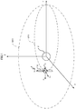
- the geostationary satellite 1 illustrated in FIG. 1 is separated from a rocket and introduced into a geostationary transfer orbit (GTO).
- GTO geostationary transfer orbit
- the geostationary satellite 1 then causes firing of a thruster 11 that is an electric propulsion thruster to obtain a thrust, and thereby shifts from the GTO to the GEO.
- the thruster 11 indicates a main thruster, such as ion thruster or plasma thruster.
- attitude control for the geostationary satellite 1 defines a geocentric inertial coordinate system having an earth 2 at the center and having the X axis, the Y axis, and the Z axis, and refers to the coordinate system as required, in order to facilitate an understanding.
- the Z axis extends through the earth 2 from the South Pole to the North Pole
- the X axis extends in the direction of vernal equinox
- the Y axis is orthogonal to each of the Z and X axes.
- the description also defines a satellite coordinate system fixed to the geostationary satellite 1 and having the x B axis, the y B axis, and the z B axis, and refers to the coordinate system as required.
- the z B axis coincides with the thrust direction of the thruster 11 included in the geostationary satellite 1
- the y B axis coincides with the rotational axis of a solar panel 12 included in the geostationary satellite 1
- the x B axis is orthogonal to each of the z B and y B axes.
- the geostationary satellite 1 includes a housing 10, the thruster 11 mounted on the housing 10, the solar panel 12, a support member 13 mounted on the housing 10 and configured to support the solar panel 12 such that the solar panel 12 is rotatable about the y B axis, and attitude control actuators 14 that control the attitude of the geostationary satellite 1 mechanically.
- the thruster 11 is mounted on the housing 10 while the thrust direction is fixed relative to the housing 10. In the satellite coordinate system defined as illustrated in FIG. 2 , the firing of the thruster 11 exerts a thrust on the geostationary satellite 1 in the positive z B axis direction.
- attitude of the geostationary satellite 1 is to be controlled, because of the thrust direction of the thruster 11 fixed relative to the housing 10.
- the four attitude control actuators 14 that control the attitude of the geostationary satellite 1 mechanically are accommodated in the housing 10. Examples of the attitude control actuators 14 include reaction wheels and control moment gyros.
- the geostationary satellite 1 also includes an attitude control apparatus accommodated in the housing 10.
- the attitude control apparatus electrically controls the attitude control actuators 14.
- the attitude control apparatus calculates an ideal attitude that is the attitude of the geostationary satellite 1 in which the thrust direction of the thruster 11 aligns with the optimum direction for minimizing the propellant consumption during the transfer from the GTO to the GEO while the panel surface 12a of the solar panel 12 is orthogonal to a unit vector s B indicating the direction of the sun represented by the dashed arrow in FIG. 2 , as explained in detail later.
- the attitude control apparatus then calculates a target attitude having a minimum deviation from the ideal attitude, in view of a movement limitation of the attitude control actuators 14.
- the attitude control apparatus acquires an actual attitude that is the attitude of the geostationary satellite 1, calculates a torque for turning the geostationary satellite 1 from the actual attitude to the target attitude, and transmits a torque instruction indicating the calculated torque to the attitude control actuators 14.
- the attitude control actuators 14 control the attitude of the geostationary satellite 1 mechanically.
- a non-illustrated thruster controller causes firing of the thruster 11 at a constant discharge amount.
- the firing of the thruster 11 at a constant discharge amount generates a constant thrust exerted on the geostationary satellite 1 during the transfer from the GTO to the GEO.
- the attitude control apparatus 20 includes an orbit calculator 21 that calculates osculating orbit elements of the current orbit of the geostationary satellite 1, an ideal thrust direction calculator 22 that calculates an ideal thrust direction of the thruster 11, a sun direction calculator 23 that calculates a direction of the sun as viewed from the geostationary satellite 1, an ideal attitude calculator 24 that calculates an ideal attitude of the geostationary satellite 1, an actual attitude calculator 25 that calculates an actual attitude that is the attitude of the geostationary satellite 1 in real, a target attitude calculator 26 that calculates a target attitude that is the attitude of the geostationary satellite 1 to be achieved, a movement limitation determiner 27 that determines conditions of the movement limitation of the attitude control actuators 14, and a torque calculator 28 that calculates a torque on the basis of the target attitude and transmits
- the ideal thrust direction indicates the optimum thrust axis of the thruster 11 for minimizing the propellant consumption during the transfer from the orbit including the geostationary satellite 1 to the GEO and minimizing the time required for the transfer.
- the ideal attitude is the attitude of the geostationary satellite 1 in which the panel surface 12a faces the sun while the z B axis aligns with the ideal thrust direction.
- the ideal attitude is preferably the attitude of the geostationary satellite 1 in which the y B axis extends in the direction orthogonal to the unit vector s B while the z B axis aligns with the ideal thrust direction.
- the target attitude is the attitude of the geostationary satellite 1 in which a deviation from the ideal attitude is minimized within the movement limitation of the attitude control actuators 14 while the panel surface 12a faces the sun.
- the target attitude is preferably the attitude of the geostationary satellite 1 in which a deviation from the ideal attitude is minimized within the movement limitation of the attitude control actuators 14 while the y B axis extends in the direction orthogonal to the unit vector s B .
- the orbit calculator 21 calculates an instantaneous position of the geostationary satellite 1 on the basis of the signal acquired from a global positioning system (GPS) receiver installed in the geostationary satellite 1, and acquires an instantaneous velocity of the geostationary satellite 1 from a speed sensor included in a sensor unit 29.
- the speed sensor calculates the velocity of the geostationary satellite 1, for example, on the basis of the wave from a ground station that communicates with the geostationary satellite 1.
- the orbit calculator 21 then calculates osculating orbit elements, which are parameters for specifying the orbit along which the geostationary satellite 1 travels, on the basis of the instantaneous position of the geostationary satellite 1 and the instantaneous velocity of the geostationary satellite 1.
- the ideal thrust direction calculator 22 calculates an ideal thrust direction that is the optimum thrust axis of the thruster 11 for minimizing the propellant consumption during the transfer to the GEO from the orbit including the geostationary satellite 1 and specified by the osculating orbit elements calculated by the orbit calculator 21.
- the ideal thrust direction calculator 22 calculates weight coefficients on the basis of the difference of the osculating orbit elements calculated by the orbit calculator 21 from target orbit elements, and calculates the sum of the results of multiplication of the direction vectors providing the maximum change rates of the individual orbit elements by the weight coefficients, thereby calculating the ideal thrust direction in the satellite coordinate system for minimizing the propellant consumption.
- the sun direction calculator 23 calculates a direction of the sun as viewed from the geostationary satellite 1.
- the sun direction calculator 23 acquires a signal from a sun sensor included in the sensor unit 29, and calculates a unit vector s B indicating the direction of the sun in the satellite coordinate system on the basis of the signal acquired from the sun sensor.
- the ideal attitude calculator 24 calculates an ideal attitude of the geostationary satellite 1 from the ideal thrust direction and the direction of the sun. In detail, the ideal attitude calculator 24 calculates the ideal attitude of the geostationary satellite 1 from the ideal thrust direction and the unit vector s B .
- the actual attitude calculator 25 acquires a signal from the sensor unit 29, which includes a magnetic sensor, a gyro sensor, and other sensors installed in the geostationary satellite 1, and calculates an actual attitude of the geostationary satellite 1 on the basis of the signal acquired from the sensor unit 29.
- the movement limitation determiner 27 determines a movement limitation defined by the capacities of the attitude control actuators 14.
- the movement limitation indicates the upper limit ⁇ MAX of the absolute value of the angular rate of the geostationary satellite 1 that can be achieved by the attitude control actuators 14.
- the target attitude calculator 26 acquires the actual attitude of the geostationary satellite 1 from the actual attitude calculator 25, acquires the ideal attitude of the geostationary satellite 1 from the ideal attitude calculator 24, and acquires the movement limitation of the attitude control actuators 14 from the movement limitation determiner 27. On the basis of the actual and ideal attitudes of the geostationary satellite 1 and the movement limitation of the attitude control actuators 14, the target attitude calculator 26 calculates a target attitude that is the attitude of the geostationary satellite 1 to be achieved.
- the torque calculator 28 acquires the actual attitude of the geostationary satellite 1 from the actual attitude calculator 25, acquires the target attitude of the geostationary satellite 1 from the target attitude calculator 26, and calculates a torque for making the attitude of the geostationary satellite 1 coincide with the target attitude.
- the torque calculator 28 then transmits a torque instruction indicating the calculated torque to the attitude control actuators 14.
- the attitude control actuators 14 control the attitude of the geostationary satellite 1 mechanically in accordance with the torque instruction.
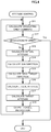
- the attitude control apparatus 20 makes the panel surface 12a of the solar panel 12 orthogonal to the direction of the sun, that is, the unit vector s B , and then executes the attitude control process illustrated in FIG. 4 .
- the attitude control apparatus 20 executes the attitude control process in a time interval T1 to control the attitude control actuators 14, so that the attitude control actuators 14 control the attitude of the geostationary satellite 1 mechanically in the constant time interval.
- the time interval T1 is a period of several seconds to several minutes, for example.
- the orbit calculator 21 calculates osculating orbit elements of the geostationary satellite 1 (Step S11). In detail, the orbit calculator 21 calculates the osculating orbit elements of the geostationary satellite 1 at a time t k and transmits the calculated osculating orbit elements to the ideal thrust direction calculator 22.
- the individual components of the attitude control apparatus 20 execute processes in synchronization with the clock signal having the time interval T1 output from a non-illustrated oscillator circuit.
- the attitude control apparatus 20 terminates the attitude control process.
- the actual attitude calculator 25 calculates an actual attitude of the geostationary satellite 1 in the geocentric inertial coordinate system on the basis of the signal acquired from an attitude sensor included in the sensor unit 29 (Step S13). In detail, the actual attitude calculator 25 calculates a matrix C BkI representing the actual attitude that is the attitude of the geostationary satellite 1 in the geocentric inertial coordinate system. The actual attitude calculator 25 then transmits the matrix C BkI to the target attitude calculator 26 and the torque calculator 28.
- the sun direction calculator 23 calculates a direction of the sun as viewed from the geostationary satellite 1 in the satellite coordinate system on the basis of the signal acquired from the sun sensor included in the sensor unit 29 (Step S14). In detail, the sun direction calculator 23 calculates a unit vector s B indicating the direction of the sun in the satellite coordinate system on the basis of the signal acquired from the sun sensor. The sun direction calculator 23 then transmits the unit vector s Bk indicating the direction of the sun calculated at the time t k to the ideal attitude calculator 24 and the target attitude calculator 26.
- the ideal thrust direction calculator 22 calculates an ideal thrust direction in the satellite coordinate system from the osculating orbit elements calculated in Step S11 (Step S15). In detail, the ideal thrust direction calculator 22 calculates weight coefficients from the difference of the osculating orbit elements calculated by the orbit calculator 21 at the time t k from the target orbit elements, and calculates the sum of the results of multiplication of the direction vectors providing the maximum change rates of the individual orbit elements by the weight coefficients, thereby calculating an ideal thrust direction u k+1 d in the satellite coordinate system at the time t k+1 for minimizing the propellant consumption. The ideal thrust direction calculator 22 then transmits the calculated ideal thrust direction u k+1 d to the ideal attitude calculator 24.
- the ideal attitude calculator 24 calculates an ideal attitude of the geostationary satellite 1 in the geocentric inertial coordinate system from the ideal thrust direction calculated in Step S15 and the direction of the sun calculated in Step S14 (Step S16). In detail, the ideal attitude calculator 24 calculates the ideal attitude of the geostationary satellite 1 from the ideal thrust direction u k+1 d at the time t k+1 and the unit vector s Bk .
- the panel surface 12a is orthogonal to the unit vector s B in the ideal attitude.
- the direction of the sun at the time t k+1 can be regarded to be identical to the direction of the sun at the time t k regardless of changes in the position and the attitude of the geostationary satellite 1 during the time interval T1, because of the extremely long distance between the geostationary satellite 1 and the sun. That is, the unit vector y Bk+1 d corresponding to the y B axis that is the rotational axis of the solar panel 12 can be regarded as orthogonal to the unit vector z Bk+1 d and the direction of the sun s Bk .
- the unit vector y Bk+1 d is represented by the expression (3) below: Math 1 y B k + 1 d ⁇ z B k + 1 d ⁇ s B k z B k + 1 d ⁇ s B k
- a matrix C Bk+1 d I is defined in the expression (5) below, which represents the unit vectors x Bk+1 d , y Bk+1 d , and z Bk+1 d of the above expressions (2) to (4) in the geocentric inertial coordinate system.
- the term [x Bk+1 d ] I in the expression (5) indicates the unit vector x Bk+1 d represented in the geocentric inertial coordinate system.
- the term [y Bk+1 d ] I indicates the unit vector y Bk+1 d represented in the geocentric inertial coordinate system
- the term [z Bk+1 d ] I indicates the unit vector z Bk+1 d represented in the geocentric inertial coordinate system.
- the ideal attitude calculator 24 transmits the matrix C Bk+1 d I to the target attitude calculator 26.
- C Bk + 1 d I [ [ x Bk + 1 d ] I , [ y Bk + 1 d ] I , [ z Bk + 1 d ] I ]
- the target attitude calculator 26 calculates a target attitude of the geostationary satellite 1 in the geocentric inertial coordinate system from the actual and ideal attitudes of the geostationary satellite 1 and the movement limitation of the attitude control actuators 14 (Step S17). In detail, the target attitude calculator 26 calculates the target attitude from the matrix C Bk+1 d I , the matrix C BkI , the unit vector s Bk , and the upper limit ⁇ MAX of the absolute value of the angular rate. The calculated target attitude preferably has a minimum deviation from the ideal attitude.
- the target attitude calculator 26 thus calculates a transformation matrix from the ideal attitude of the geostationary satellite 1 at the time t k+1 to the target attitude of the geostationary satellite 1 at the time t k+1 , and minimizes the trace of the transformation matrix.
- the target attitude calculator 26 thus calculates the target attitude having the minimum deviation from the ideal attitude. The specific calculation process is explained.
- the transformation matrix C BkBk+1 d is defined in the expression (6) below, which represents vector transformation from the ideal attitude of the geostationary satellite 1 at the time t k+1 to the actual attitude of the geostationary satellite 1 at the time t k .
- C IBk+1 d indicates a transposed matrix of the matrix C Bk+1 d I .
- C BkBk + 1 d C BkI C IBk + 1 d
- the transformation matrix C Bk+1Bk from the actual attitude of the geostationary satellite 1 at the time t k to the target attitude of the geostationary satellite 1 at the time t k+1 is defined in the expression (7) below.
- the right-hand side of the expression (7) indicates conducting a turn about the unit vector s Bk by an angle ⁇ and then conducting a turn about the y B axis by an angle ⁇ , thereby making the attitude of the geostationary satellite 1 coincide with the target attitude.
- C 2 ( ⁇ ) is a coordinate transformation matrix indicating a turn about the y B axis by the angle ⁇ .
- E 3 is a three-dimensional identity matrix
- s Bk T is a transposed matrix of the s Bk
- s Bk x is a cross-product matrix of the s Bk .
- the above expression (9) represents a deviation from the ideal attitude of the geostationary satellite 1. Accordingly, the target attitude closest to the ideal attitude of the geostationary satellite 1 can be obtained by calculating angles ⁇ and ⁇ that provide the minimum trace of the transformation matrix C Bk+1Bk+1 d in the expression (9) while satisfying the expression (10) below based on the upper limit ⁇ MAX of the absolute value of the angular rate.
- the transformation matrix C Bk+1Bk is a linear combination of the angles ⁇ and ⁇ .
- the transformation matrix C BkBk+1 d is the product of the matrix C BkI representing actual attitude of the geostationary satellite 1 at the time t k and the transposed matrix C IBk+1 d of the matrix C Bk+1 d I representing ideal attitude of the geostationary satellite 1 at the time t k+1 , as defined in the above expression (6).
- the transformation matrix C Bk+1Bk+1 d is therefore a linear combination of the angles ⁇ and ⁇ .
- the target attitude calculator 26 calculates the target attitude by solving the mathematical programming problem of minimizing the trace of the transformation matrix C Bk+1Bk+1 d , which is an evaluation function configured by a linear combination of the angles ⁇ and ⁇ , under the quadratic constraint represented by the above expression (10).
- This configuration does not require a process of repetitively execute calculations while changing a variable, for example, for solving the mathematical programming problem, and can therefore improve the efficiency of calculating the target attitude.
- the attitude control apparatus 20 that executes the above-explained process makes the panel surface 12a of the solar panel 12 orthogonal to the direction of the sun at the start of attitude control.
- the attitude control from the actual attitude of the geostationary satellite 1 at the time t k to the target attitude of the geostationary satellite 1 at the time t k+1 is achieved by a turn about the unit vector s Bk and a turn about the y B axis. That is, the panel surface 12a of the solar panel 12 is maintained to be orthogonal to the direction of the sun in the attitude control during the transfer from the GTO to the GEO. This configuration can prevent a reduction in power generation efficiency of the solar panel 12 during the orbit transfer.
- the attitude of the geostationary satellite 1 is made coincide with the target attitude having a minimum deviation from the ideal attitude of the geostationary satellite 1 in association with the ideal thrust direction that is an optimum thrust direction of the thruster 11 for minimizing the propellant consumption during the transfer from the GTO to the GEO.
- This configuration can minimize the propellant consumption during the orbit transfer.
- the torque calculator 28 calculates a torque required for turning the geostationary satellite 1 from the actual attitude to the target attitude on the basis of the actual attitude of the geostationary satellite 1 calculated in Step S13 and the target attitude of the geostationary satellite 1 calculated in Step S17.
- the torque calculator 28 then outputs a torque instruction indicating the required torque to the attitude control actuators 14 (Step S18).
- the torque calculator 28 calculates the torque for making the attitude of the geostationary satellite 1 coincide with the target attitude at the time t k+1 from the matrix C BkI representing the actual attitude of the geostationary satellite 1 and the matrix C B * k+1I indicating the target attitude of the geostationary satellite 1.
- the torque calculator 28 transmits the torque instruction indicating the calculated torque to the attitude control actuators 14.
- the attitude control actuators 14 control the attitude of the geostationary satellite 1 mechanically in accordance with the torque instruction.
- the mechanical control of the attitude control actuators 14 over the attitude of the geostationary satellite 1 in accordance with the torque instruction changes the orientation of the geostationary satellite 1, so that the attitude of the geostationary satellite 1 coincides with the target attitude.
- the attitude control apparatus 20 executes the above-explained process repetitively in the time interval T1 until arrival of the geostationary satellite 1 at the GEO.
- the attitude control apparatus 20 calculates a target attitude that is the attitude of the geostationary satellite 1 in which a deviation from the ideal attitude is minimized within the movement limitation of the attitude control actuators 14 while the panel surface 12a faces the sun preferably while the y B axis that is the rotational axis extends in the direction orthogonal to the sun direction s B .
- a torque instruction indicating the torque for turning the geostationary satellite 1 from the actual attitude to the calculated target attitude makes the attitude of the geostationary satellite 1 coincide with the target attitude, thereby preventing a reduction in power generation efficiency of the solar panel 12 during the transfer from the GTO to the GEO.
- calculated is the target attitude having the minimum deviation from the ideal attitude of the geostationary satellite 1 in association with the ideal thrust direction that is an optimum thrust direction of the thruster 11 for minimizing the propellant consumption during the transfer from the GTO to the GEO. This configuration can minimize the propellant consumption during the orbit transfer.
- the above-explained process of calculating the target attitude by the target attitude calculator 26 is a mere example.
- the geostationary satellite 1 and the attitude control apparatus 20 according to Embodiment 2 have the same configurations as those according to Embodiment 1, these embodiments have differences in the processes executed by the target attitude calculator 26 and the movement limitation determiner 27.
- the movement limitation determiner 27 determines a maximum angular momentum envelope surface, which indicates a collection of maximum angular momenta that can be generated by the control moment gyros or reaction wheels serving as the attitude control actuators 14. The movement limitation determiner 27 then transmits the maximum angular momentum envelope surface to the target attitude calculator 26. The following is an additional description about the maximum angular momentum envelope surface.
- the angular momentum that can be generated by each of the attitude control actuators 14 in the designated direction is uniquely determined.
- the sum of such momenta provides the maximum angular momenta that can be generated by all the attitude control actuators 14 in the designated direction.
- the surface defined by these maximum angular momenta is called a maximum angular momentum envelope surface.
- the target attitude calculator 26 calculates a target attitude from the matrix C Bk+1 d I , the matrix C BkI , the unit vector s Bk , and the maximum angular momentum envelope surface.
- the calculated target attitude preferably has a minimum deviation from the ideal attitude.
- the target attitude calculator 26 thus calculates a transformation matrix from the ideal attitude of the geostationary satellite 1 at the time t k+1 to the actual attitude of the geostationary satellite 1 at the time t k , and then solves the inverse kinematics problem of the transformation matrix, thereby obtaining an ideal rotational angle ⁇ d about the unit vector s Bk and an ideal rotational angle ⁇ d about the y B axis.
- the target attitude calculator 26 then calculates a target attitude defined by angles ⁇ and ⁇ close to the ideal rotational angles ⁇ d and ⁇ d .
- the target attitude calculator 26 solves the inverse kinematics problem of the transformation matrix C BkBk+1 d represented by the above expression (6), and thereby obtains the ideal rotational angle ⁇ d about the unit vector s Bk and the ideal rotational angle ⁇ d about the y B axis.
- a theoretical optimum rotational axis [ ⁇ d ] Bk regardless of the movement limitation of the attitude control actuators 14 is defined in the expression (12) below.
- the target attitude calculator 26 calculates an upper limit h max of the angular momentum of a turn of the geostationary satellite 1 about the rotational axis [ ⁇ d ] Bk that can be achieved by the attitude control actuators 14, on the basis of the maximum angular momentum envelope surface.
- the target attitude calculator 26 calculates an upper limit ⁇ MAX of the absolute value of the angular rate of the geostationary satellite 1 about the rotational axis [ ⁇ d ] Bk that can be achieved by the attitude control actuators 14 as in the expression (13) below.
- the target attitude calculator 26 then transmits the upper limit ⁇ MAX of the absolute value of the angular rate to the target attitude calculator 26.
- the target attitude calculator 26 then transmits the upper limit ⁇ MAX of the absolute value of the angular rate to the target attitude calculator 26.
- I B indicates the inertia matrix of the geostationary satellite 1.
- the inertia matrix I B of the geostationary satellite 1 has three rows and three columns, contains a moment of inertia of the geostationary satellite 1 at the diagonal elements, and a product of inertia at the off-diagonal elements.
- ⁇ MAX h max / I B ⁇ d Bk
- the target attitude calculator 26 then calculates angles ⁇ and ⁇ having minimum deviations from the ideal rotational angle ⁇ d about the unit vector s Bk and the ideal rotational angle ⁇ d about the y B axis, respectively, while satisfying the above expression (10), and thereby obtains the target attitude closest to the ideal attitude of the geostationary satellite 1.
- the angles ⁇ and ⁇ obtained as explained above are defined as ⁇ * and ⁇ *, respectively.
- the transformation matrix from the actual attitude of the geostationary satellite 1 at the time t k to the target attitude of the geostationary satellite 1 at the time t k+1 , obtained by substituting the angles ⁇ * and ⁇ * in the above expression (7), is defined as C B * k+1Bk .
- the matrix C B * k+1I indicating the target attitude of the geostationary satellite 1 in the geocentric inertial coordinate system at the time t k+1 is represented by the above expression (11).
- the target attitude calculator 26 then transmits the calculated matrix C B * k+1I indicating the target attitude to the torque calculator 28.
- the attitude control apparatus 20 that executes the above-explained process makes the panel surface 12a of the solar panel 12 orthogonal to the direction of the sun at the start of attitude control.
- the attitude control from the actual attitude of the geostationary satellite 1 at the time t k to the target attitude of the geostationary satellite 1 at the time t k+1 is achieved by a turn about the unit vector s Bk and a turn about the y B axis. That is, the panel surface 12a of the solar panel 12 is maintained to be orthogonal to the direction of the sun in the attitude control during the transfer from the GTO to the GEO.
- This configuration can prevent a reduction in power generation efficiency of the solar panel 12 during the orbit transfer. Furthermore, the attitude of the geostationary satellite 1 is made coincide with the target attitude having a minimum deviation from the ideal attitude of the geostationary satellite 1 in association with the ideal thrust direction that is an optimum thrust direction of the thruster 11 for minimizing the propellant consumption during the transfer from the GTO to the GEO. This configuration can minimize the propellant consumption during the orbit transfer.
- the attitude control apparatus 20 turns the geostationary satellite 1 about the ideal rotational axis at an angular rate in view of the movement limitation of the attitude control actuators 14, and thus makes the attitude of the geostationary satellite 1 coincide with the target attitude.
- This configuration can prevent a reduction in power generation efficiency of the solar panel 12 during the transfer from the GTO to the GEO.
- the angular momenta that can be generated by the attitude control actuators 14 can be maximized even in a geostationary satellite 1 in which the principal axis of inertia providing the maximum second moment of inertia differs from the principal axis of inertia providing the minimum second moment of inertia, for example.
- the target attitude having the minimum deviation from the ideal attitude of the geostationary satellite 1 in association with the ideal thrust direction (optimum thrust axis of the thruster 11 for minimizing the propellant consumption during the orbit transfer and minimizing the time required for the transfer).
- This configuration can minimize the propellant consumption during the orbit transfer.
- FIG. 5 illustrates a hardware configuration of the attitude control apparatus according to the embodiments.
- the attitude control apparatus 20 has a hardware configuration for controlling the individual components, which includes a processor 31, a memory 32, and an interface 33. The functions of these components can be performed when the processor 31 executes the program stored in the memory 32.
- the interface 33 connects the individual components to each other to establish communication.
- the interface 33 may be replaced with multiple types of interfaces as required.
- FIG. 5 illustrates an example in which the attitude control apparatus 20 includes the single processor 31 and the single memory 32
- the attitude control apparatus 20 may include a plurality of processors 31 and a plurality of memories 32.
- the processors 31 and the memories 32 perform the individual functions in cooperation with each other.
- the attitude control apparatus 20 is connected via the interface 33 to the sensor unit 29 and the attitude control actuators 14.
- the center for executing the control process which includes the processor 31, the memory 32, and the interface 33, may be configured by a general computer system without a dedicated system.
- the computer program for executing the above operations may be stored into a non-transitory computer-readable recording medium, such as a flexible disk, a compact disc read-only memory (CD-ROM), or a digital versatile disc read-only memory (DVD-ROM), or may be stored into a storage device on a communication network.
- the computer program stored in the non-transitory recording medium or the storage device is installed into a computer, and thereby causes the computer to function as the attitude control apparatus 20 for executing the above process.
- the initial orbit, into which the geostationary satellite 1 separated from the rocket is introduced may be an orbit other than the GTO.
- the geostationary satellite 1 may be introduced into a low earth orbit (LEO), a super synchronous orbit (SSO), or other orbits.
- the attitude control apparatus 20 may conduct attitude control of a satellite other than the geostationary satellite 1.
- the attitude control apparatus 20 may control the attitude of a non-geostationary satellite that shifts from the initial orbit to a geocentric orbit.
- the target orbit is not the GEO but any geocentric orbit.
- the geostationary satellite 1 may include a plurality of thrusters 11.
- the z B axis in the satellite coordinate system indicates a synthetic thrust axis formed by synthetizing the individual thrust axes of the thrusters 11.
- the thruster 11 may also be a chemical thruster.
- the above-described embodiments provide a mere example of the configuration of the attitude control apparatus 20 and the operations of the individual components.
- the attitude control apparatus 20 may be installed in a ground station.
- the the sun direction calculator 23 may calculate a direction of the sun from the solar calendar.
- the attitude control apparatus 20 may exclude the movement limitation determiner 27, and the target attitude calculator 26 may retain the movement limitation of the attitude control actuators 14 in advance.
- the ideal thrust direction calculator 22 may calculate the optimum thrust direction of the thruster 11 for minimizing the propellant consumption during the transfer from the orbit including the geostationary satellite 1 to the GEO and minimizing the time required for the transfer. This configuration can minimize the propellant consumption during the transfer and minimize the time required for the transfer.
- the thruster controller may provide the thruster 11 with a thruster instruction value for varying the discharge amount from the thruster 11 during the transfer from the GTO to the GEO.
- the above-described definition of the satellite coordinate system is a mere example.
- the satellite coordinate system may be any coordinate system, in which the y B axis indicating the rotational axis of the solar panel 12 extends in a predetermined direction relative to the z B axis indicating the ideal thrust direction.
- attitude control actuators 14 is a mere example and may be replaced with the upper limit of the rotational rate of flywheels or reaction wheels serving as the attitude control actuators 14.
- the movement limitation of the attitude control actuators 14 may be the upper limit of the absolute value of the angular rate of the geostationary satellite 1 that can be achieved by the attitude control actuators 14, as in Embodiment 1.
Landscapes
- Engineering & Computer Science (AREA)
- Remote Sensing (AREA)
- Aviation & Aerospace Engineering (AREA)
- Chemical & Material Sciences (AREA)
- Combustion & Propulsion (AREA)
- Radar, Positioning & Navigation (AREA)
- Automation & Control Theory (AREA)
- Life Sciences & Earth Sciences (AREA)
- Sustainable Development (AREA)
- Control Of Position, Course, Altitude, Or Attitude Of Moving Bodies (AREA)
Abstract
Description
- The present invention relates to an attitude control apparatus for controlling the attitude of a satellite, a satellite, a method of controlling attitude, and a program.
- A geostationary satellite is separated from a rocket and introduced into an orbit, such as low earth orbit (LEO), geostationary transfer orbit (GTO), or super synchronous orbit (SSO). The geostationary satellite then causes firing of a thruster mounted thereon and thus obtains a thrust, thereby shifting from the initial orbit, into which the geostationary satellite has been introduced, to the geostationary earth orbit (GEO). Examples of the thruster include a chemical thruster and an electric propulsion thruster.
- The chemical thruster can generate a greater thrust, and therefore requires a shorter time for orbit transfer from the GTO to the GEO but requires a higher propellant consumption, in comparison to the electric propulsion thruster. In contrast, the electric propulsion thruster requires a longer time for orbit transfer from the GTO to the GEO but requires a lower propellant consumption, which means a higher specific impulse, in comparison to the chemical thruster.
- In either case of the chemical thruster and the electric propulsion thruster, in order to shorten the time required for orbit transfer while reducing the propellant consumption during the orbit transfer, the thrust direction of the thruster should extend in a direction appropriate for transfer of the satellite to the target orbit. In addition, in order to cause firing of the thruster, the panel surface of a solar array panel (SAP) for generating electric power to be fed to the thruster should face the direction of the sun. In view of these requirements, some satellites are equipped with attitude control apparatuses that control the attitudes of the satellites during orbit transfer. An example of these attitude control apparatuses is disclosed in Patent Literature 1. The attitude control apparatus disclosed in Patent Literature 1 controls the attitude of a satellite so as to make the panel surface of a SAP orthogonal to the sun vector and make the thrust vector orthogonal to the rotational axis of the SAP.
- Patent Literature 1: Unexamined
Japanese Patent Application Publication JP 2001-18899 A - The mechanical attitude control of the satellite is executed by attitude control actuators installed in the satellite. Unfortunately, the attitude control apparatus disclosed in Patent Literature 1 controls the attitude of the satellite regardless of the movement limitation of the attitude control actuators. This configuration may lead to a problem that the actual attitude of the satellite cannot follow the target attitude of the satellite. The panel surface of the SAP therefore fails to face the direction of the sun, resulting in a reduction in power generation efficiency of the SAP. The similar problems arise not only in a geostationary satellite but also in a non-geostationary satellite, which shifts from the initial orbit to a geocentric orbit.
- An objective of the present invention, which has been accomplished in view of the above situations, is to provide an attitude control apparatus, a satellite, a method of controlling attitude, and a program, that can prevent a reduction in power generation efficiency of a SAP during orbit transfer.
- In order to achieve the above objective, an attitude control apparatus according to the present invention includes an ideal thrust direction calculator, an ideal attitude calculator, a target attitude calculator, and a torque calculator. The ideal thrust direction calculator acquires the position of a satellite including a thruster and a solar panel having a panel surface rotatable about a rotational axis, and calculates an ideal thrust direction that is a thrust direction of the thruster for minimizing a propellant consumption in firing of the thruster during transfer of the satellite to a target orbit. The ideal attitude calculator calculates an ideal attitude that is the attitude of the satellite in which the panel surface faces the sun while the thrust direction aligns with the ideal thrust direction.
- The target attitude calculator acquires a movement limitation of an attitude control actuator for controlling an attitude of the satellite mechanically, and calculates a target attitude that is an attitude of the satellite in which a deviation from the ideal attitude is minimized within the movement limitation while the panel surface faces the sun. The torque calculator acquires an actual attitude that is an attitude of the satellite, calculates a torque for turning the satellite from the actual attitude to the target attitude, and transmits a torque instruction indicating the calculated torque to the attitude control actuator.
- The attitude control apparatus according to the present invention calculates the target attitude that is the attitude of the satellite in which a deviation from the ideal attitude is minimized within the movement limitation of the attitude control actuator while the panel surface faces the sun. Since the torque instruction indicating the torque for turning the satellite from the actual attitude to the target attitude is transmitted to the attitude control actuator, the configuration can make the attitude of the satellite coincide with the target attitude and thus prevent a reduction in power generation efficiency of the SAP during the orbit transfer.
-
- FIG. 1
- illustrates a geostationary satellite according to Embodiment 1 of the present invention;
- FIG. 2
- illustrates a configuration of the geostationary satellite according to Embodiment 1;
- FIG. 3
- is a block diagram illustrating a configuration of an attitude control apparatus according to Embodiment 1;
- FIG. 4
- is a flowchart illustrating an example of attitude control operation executed by the attitude control apparatus according to Embodiment 1; and
- FIG. 5
- illustrates a hardware configuration of the attitude control apparatus according to the embodiments.
- An attitude control apparatus according to embodiments of the invention is described in detail with reference to the drawings. Components that are the same or equivalent are assigned the same reference signs throughout the drawings.
- An attitude control apparatus according to Embodiment 1 is described focusing on an exemplary attitude control apparatus that is installed in a geostationary satellite, which is an exemplary satellite, and controls the attitude of the geostationary satellite during transfer from the initial orbit, into which the geostationary satellite has been introduced, to a geostationary earth orbit (GEO) that is a target orbit. The geostationary satellite 1 illustrated in
FIG. 1 is separated from a rocket and introduced into a geostationary transfer orbit (GTO). The geostationary satellite 1 then causes firing of athruster 11 that is an electric propulsion thruster to obtain a thrust, and thereby shifts from the GTO to the GEO. - The
thruster 11 indicates a main thruster, such as ion thruster or plasma thruster. The following description of attitude control for the geostationary satellite 1 defines a geocentric inertial coordinate system having anearth 2 at the center and having the X axis, the Y axis, and the Z axis, and refers to the coordinate system as required, in order to facilitate an understanding. In this geocentric inertial coordinate system, the Z axis extends through theearth 2 from the South Pole to the North Pole, the X axis extends in the direction of vernal equinox, and the Y axis is orthogonal to each of the Z and X axes. - As illustrated in
FIG. 2 , the description also defines a satellite coordinate system fixed to the geostationary satellite 1 and having the xB axis, the yB axis, and the zB axis, and refers to the coordinate system as required. In this satellite coordinate system, the zB axis coincides with the thrust direction of thethruster 11 included in the geostationary satellite 1, the yB axis coincides with the rotational axis of asolar panel 12 included in the geostationary satellite 1, and the xB axis is orthogonal to each of the zB and yB axes. - The geostationary satellite 1 includes a
housing 10, thethruster 11 mounted on thehousing 10, thesolar panel 12, asupport member 13 mounted on thehousing 10 and configured to support thesolar panel 12 such that thesolar panel 12 is rotatable about the yB axis, andattitude control actuators 14 that control the attitude of the geostationary satellite 1 mechanically. Thethruster 11 is mounted on thehousing 10 while the thrust direction is fixed relative to thehousing 10. In the satellite coordinate system defined as illustrated inFIG. 2 , the firing of thethruster 11 exerts a thrust on the geostationary satellite 1 in the positive zB axis direction. - In order to adjust the direction of the thrust exerted on the geostationary satellite 1, the attitude of the geostationary satellite 1 is to be controlled, because of the thrust direction of the
thruster 11 fixed relative to thehousing 10. The fourattitude control actuators 14 that control the attitude of the geostationary satellite 1 mechanically are accommodated in thehousing 10. Examples of theattitude control actuators 14 include reaction wheels and control moment gyros. - Although not illustrated in
FIG. 2 , the geostationary satellite 1 also includes an attitude control apparatus accommodated in thehousing 10. The attitude control apparatus electrically controls theattitude control actuators 14. The attitude control apparatus calculates an ideal attitude that is the attitude of the geostationary satellite 1 in which the thrust direction of thethruster 11 aligns with the optimum direction for minimizing the propellant consumption during the transfer from the GTO to the GEO while thepanel surface 12a of thesolar panel 12 is orthogonal to a unit vector sB indicating the direction of the sun represented by the dashed arrow inFIG. 2 , as explained in detail later. - The attitude control apparatus then calculates a target attitude having a minimum deviation from the ideal attitude, in view of a movement limitation of the
attitude control actuators 14. The attitude control apparatus then acquires an actual attitude that is the attitude of the geostationary satellite 1, calculates a torque for turning the geostationary satellite 1 from the actual attitude to the target attitude, and transmits a torque instruction indicating the calculated torque to theattitude control actuators 14. On the basis of this torque instruction, theattitude control actuators 14 control the attitude of the geostationary satellite 1 mechanically. - During the transfer from the GTO to the GEO, a non-illustrated thruster controller causes firing of the
thruster 11 at a constant discharge amount. The firing of thethruster 11 at a constant discharge amount generates a constant thrust exerted on the geostationary satellite 1 during the transfer from the GTO to the GEO. - The following description is directed to an
attitude control apparatus 20, which directs the thrust direction of thethruster 11 to the optimum direction for minimizing the propellant consumption during the transfer from the GTO to the GEO while a constant thrust is exerted as explained above. With reference toFIG. 3 , theattitude control apparatus 20 includes anorbit calculator 21 that calculates osculating orbit elements of the current orbit of the geostationary satellite 1, an ideal thrust direction calculator 22 that calculates an ideal thrust direction of thethruster 11, asun direction calculator 23 that calculates a direction of the sun as viewed from the geostationary satellite 1, anideal attitude calculator 24 that calculates an ideal attitude of the geostationary satellite 1, anactual attitude calculator 25 that calculates an actual attitude that is the attitude of the geostationary satellite 1 in real, atarget attitude calculator 26 that calculates a target attitude that is the attitude of the geostationary satellite 1 to be achieved, amovement limitation determiner 27 that determines conditions of the movement limitation of theattitude control actuators 14, and atorque calculator 28 that calculates a torque on the basis of the target attitude and transmits a torque instruction to theattitude control actuators 14. - The ideal thrust direction indicates the optimum thrust axis of the
thruster 11 for minimizing the propellant consumption during the transfer from the orbit including the geostationary satellite 1 to the GEO and minimizing the time required for the transfer. The ideal attitude is the attitude of the geostationary satellite 1 in which thepanel surface 12a faces the sun while the zB axis aligns with the ideal thrust direction. The ideal attitude is preferably the attitude of the geostationary satellite 1 in which the yB axis extends in the direction orthogonal to the unit vector sB while the zB axis aligns with the ideal thrust direction. - The target attitude is the attitude of the geostationary satellite 1 in which a deviation from the ideal attitude is minimized within the movement limitation of the
attitude control actuators 14 while thepanel surface 12a faces the sun. The target attitude is preferably the attitude of the geostationary satellite 1 in which a deviation from the ideal attitude is minimized within the movement limitation of theattitude control actuators 14 while the yB axis extends in the direction orthogonal to the unit vector sB. - The
orbit calculator 21 calculates an instantaneous position of the geostationary satellite 1 on the basis of the signal acquired from a global positioning system (GPS) receiver installed in the geostationary satellite 1, and acquires an instantaneous velocity of the geostationary satellite 1 from a speed sensor included in asensor unit 29. The speed sensor calculates the velocity of the geostationary satellite 1, for example, on the basis of the wave from a ground station that communicates with the geostationary satellite 1. Theorbit calculator 21 then calculates osculating orbit elements, which are parameters for specifying the orbit along which the geostationary satellite 1 travels, on the basis of the instantaneous position of the geostationary satellite 1 and the instantaneous velocity of the geostationary satellite 1. - The ideal thrust direction calculator 22 calculates an ideal thrust direction that is the optimum thrust axis of the
thruster 11 for minimizing the propellant consumption during the transfer to the GEO from the orbit including the geostationary satellite 1 and specified by the osculating orbit elements calculated by theorbit calculator 21. In detail, the ideal thrust direction calculator 22 calculates weight coefficients on the basis of the difference of the osculating orbit elements calculated by theorbit calculator 21 from target orbit elements, and calculates the sum of the results of multiplication of the direction vectors providing the maximum change rates of the individual orbit elements by the weight coefficients, thereby calculating the ideal thrust direction in the satellite coordinate system for minimizing the propellant consumption. - The
sun direction calculator 23 calculates a direction of the sun as viewed from the geostationary satellite 1. In detail, thesun direction calculator 23 acquires a signal from a sun sensor included in thesensor unit 29, and calculates a unit vector sB indicating the direction of the sun in the satellite coordinate system on the basis of the signal acquired from the sun sensor. - The
ideal attitude calculator 24 calculates an ideal attitude of the geostationary satellite 1 from the ideal thrust direction and the direction of the sun. In detail, theideal attitude calculator 24 calculates the ideal attitude of the geostationary satellite 1 from the ideal thrust direction and the unit vector sB. - The
actual attitude calculator 25 acquires a signal from thesensor unit 29, which includes a magnetic sensor, a gyro sensor, and other sensors installed in the geostationary satellite 1, and calculates an actual attitude of the geostationary satellite 1 on the basis of the signal acquired from thesensor unit 29. - The
movement limitation determiner 27 determines a movement limitation defined by the capacities of theattitude control actuators 14. In this embodiment, the movement limitation indicates the upper limit ωMAX of the absolute value of the angular rate of the geostationary satellite 1 that can be achieved by theattitude control actuators 14. - The
target attitude calculator 26 acquires the actual attitude of the geostationary satellite 1 from theactual attitude calculator 25, acquires the ideal attitude of the geostationary satellite 1 from theideal attitude calculator 24, and acquires the movement limitation of theattitude control actuators 14 from themovement limitation determiner 27. On the basis of the actual and ideal attitudes of the geostationary satellite 1 and the movement limitation of theattitude control actuators 14, thetarget attitude calculator 26 calculates a target attitude that is the attitude of the geostationary satellite 1 to be achieved. - The
torque calculator 28 acquires the actual attitude of the geostationary satellite 1 from theactual attitude calculator 25, acquires the target attitude of the geostationary satellite 1 from thetarget attitude calculator 26, and calculates a torque for making the attitude of the geostationary satellite 1 coincide with the target attitude. Thetorque calculator 28 then transmits a torque instruction indicating the calculated torque to theattitude control actuators 14. Theattitude control actuators 14 control the attitude of the geostationary satellite 1 mechanically in accordance with the torque instruction. - A process of controlling the attitude of the geostationary satellite 1 executed by the
attitude control apparatus 20 having the above-described configuration is explained with reference toFIG. 4 . Theattitude control apparatus 20 makes thepanel surface 12a of thesolar panel 12 orthogonal to the direction of the sun, that is, the unit vector sB, and then executes the attitude control process illustrated inFIG. 4 . Theattitude control apparatus 20 executes the attitude control process in a time interval T1 to control theattitude control actuators 14, so that theattitude control actuators 14 control the attitude of the geostationary satellite 1 mechanically in the constant time interval. The time interval T1 is a period of several seconds to several minutes, for example. - The
orbit calculator 21 calculates osculating orbit elements of the geostationary satellite 1 (Step S11). In detail, theorbit calculator 21 calculates the osculating orbit elements of the geostationary satellite 1 at a time tk and transmits the calculated osculating orbit elements to the ideal thrust direction calculator 22. The individual components of theattitude control apparatus 20 execute processes in synchronization with the clock signal having the time interval T1 output from a non-illustrated oscillator circuit. When the osculating orbit elements calculated in Step S11 are equal to the osculating orbit elements of a geostationary orbit (Step S12; Yes), theattitude control apparatus 20 terminates the attitude control process. - When the osculating orbit elements calculated in Step S11 are not equal to the osculating orbit elements of the geostationary orbit (Step S12; No), the
actual attitude calculator 25 calculates an actual attitude of the geostationary satellite 1 in the geocentric inertial coordinate system on the basis of the signal acquired from an attitude sensor included in the sensor unit 29 (Step S13). In detail, theactual attitude calculator 25 calculates a matrix CBkI representing the actual attitude that is the attitude of the geostationary satellite 1 in the geocentric inertial coordinate system. Theactual attitude calculator 25 then transmits the matrix CBkI to thetarget attitude calculator 26 and thetorque calculator 28. - The
sun direction calculator 23 calculates a direction of the sun as viewed from the geostationary satellite 1 in the satellite coordinate system on the basis of the signal acquired from the sun sensor included in the sensor unit 29 (Step S14). In detail, thesun direction calculator 23 calculates a unit vector sB indicating the direction of the sun in the satellite coordinate system on the basis of the signal acquired from the sun sensor. Thesun direction calculator 23 then transmits the unit vector sBk indicating the direction of the sun calculated at the time tk to theideal attitude calculator 24 and thetarget attitude calculator 26. - The ideal thrust direction calculator 22 calculates an ideal thrust direction in the satellite coordinate system from the osculating orbit elements calculated in Step S11 (Step S15). In detail, the ideal thrust direction calculator 22 calculates weight coefficients from the difference of the osculating orbit elements calculated by the
orbit calculator 21 at the time tk from the target orbit elements, and calculates the sum of the results of multiplication of the direction vectors providing the maximum change rates of the individual orbit elements by the weight coefficients, thereby calculating an ideal thrust direction uk+1 d in the satellite coordinate system at the time tk+1 for minimizing the propellant consumption. The ideal thrust direction calculator 22 then transmits the calculated ideal thrust direction uk+1 d to theideal attitude calculator 24. The time tk+1 is represented by the expression (1) below using the time tk and the time interval T1:
- The
ideal attitude calculator 24 calculates an ideal attitude of the geostationary satellite 1 in the geocentric inertial coordinate system from the ideal thrust direction calculated in Step S15 and the direction of the sun calculated in Step S14 (Step S16). In detail, theideal attitude calculator 24 calculates the ideal attitude of the geostationary satellite 1 from the ideal thrust direction uk+1 d at the time tk+1 and the unit vector sBk. The respective unit vectors corresponding to the xB axis, the yB axis, and the zB axis in the satellite coordinate system in the case where the attitude of the geostationary satellite 1 coincides with the ideal attitude at the time tk+1 are represented by xBk+1 d, yBk+1 d, and zBk+1 d. Since the zB axis aligns with the ideal thrust direction in the ideal attitude as described above, the zB axis is represented by the expression (2) below:
- In addition, the
panel surface 12a is orthogonal to the unit vector sB in the ideal attitude. The direction of the sun at the time tk+1 can be regarded to be identical to the direction of the sun at the time tk regardless of changes in the position and the attitude of the geostationary satellite 1 during the time interval T1, because of the extremely long distance between the geostationary satellite 1 and the sun. That is, the unit vector yBk+1 d corresponding to the yB axis that is the rotational axis of thesolar panel 12 can be regarded as orthogonal to the unit vector zBk+1 d and the direction of the sun sBk. Accordingly, the unit vector yBk+1 d is represented by the expression (3) below:
Math 1
- Because the satellite coordinate system is a right-handed orthogonal coordinate system, the unit vector xBk+1 d is represented by the expression (4) below:

- A matrix CBk+1 d I is defined in the expression (5) below, which represents the unit vectors xBk+1 d, yBk+1 d, and zBk+1 d of the above expressions (2) to (4) in the geocentric inertial coordinate system. The term [xBk+1 d]I in the expression (5) indicates the unit vector xBk+1 d represented in the geocentric inertial coordinate system. Also, the term [yBk+1 d]I indicates the unit vector yBk+1 d represented in the geocentric inertial coordinate system, and the term [zBk+1 d]I indicates the unit vector zBk+1 d represented in the geocentric inertial coordinate system. The
ideal attitude calculator 24 transmits the matrix CBk+1 d I to thetarget attitude calculator 26.
- The
target attitude calculator 26 calculates a target attitude of the geostationary satellite 1 in the geocentric inertial coordinate system from the actual and ideal attitudes of the geostationary satellite 1 and the movement limitation of the attitude control actuators 14 (Step S17). In detail, thetarget attitude calculator 26 calculates the target attitude from the matrix CBk+1 d I, the matrix CBkI, the unit vector sBk, and the upper limit ωMAX of the absolute value of the angular rate. The calculated target attitude preferably has a minimum deviation from the ideal attitude. - The
target attitude calculator 26 thus calculates a transformation matrix from the ideal attitude of the geostationary satellite 1 at the time tk+1 to the target attitude of the geostationary satellite 1 at the time tk+1, and minimizes the trace of the transformation matrix. Thetarget attitude calculator 26 thus calculates the target attitude having the minimum deviation from the ideal attitude. The specific calculation process is explained. - The transformation matrix CBkBk+1 d is defined in the expression (6) below, which represents vector transformation from the ideal attitude of the geostationary satellite 1 at the time tk+1 to the actual attitude of the geostationary satellite 1 at the time tk. In the expression (6), CIBk+1 d indicates a transposed matrix of the matrix CBk+1 d I.

- The transformation matrix CBk+1Bk from the actual attitude of the geostationary satellite 1 at the time tk to the target attitude of the geostationary satellite 1 at the time tk+1 is defined in the expression (7) below. The right-hand side of the expression (7) indicates conducting a turn about the unit vector sBk by an angle θ and then conducting a turn about the yB axis by an angle ϕ, thereby making the attitude of the geostationary satellite 1 coincide with the target attitude. In the expression (7), C2(ϕ) is a coordinate transformation matrix indicating a turn about the yB axis by the angle ϕ. In the expression (7), E3 is a three-dimensional identity matrix, sBk T is a transposed matrix of the sBk, and sBk x is a cross-product matrix of the sBk.
Math 2
- While the orbital period of the geostationary satellite 1 is approximately 12 to 24 hours, the time interval T1 is several seconds to several minutes. The angles θ and ϕ can thus be regarded as extremely small values. The above expression (7) can therefore be approximated by the expression (8) below. In the expression (8), e2 is a matrix defined by [0 1 0]T. In the expression (8), the transformation matrix CBk+1Bk is represented by a linear combination of the angles θ and ϕ.
Math 3
- The transformation matrix CBk+1Bk+1 d from the ideal attitude of the geostationary satellite 1 at the time tk+1 to the target attitude of the geostationary satellite 1 at the time tk+1 is defined in the expression (9) below.
Math 4
- The above expression (9) represents a deviation from the ideal attitude of the geostationary satellite 1. Accordingly, the target attitude closest to the ideal attitude of the geostationary satellite 1 can be obtained by calculating angles θ and ϕ that provide the minimum trace of the transformation matrix CBk+1Bk+1 d in the expression (9) while satisfying the expression (10) below based on the upper limit ωMAX of the absolute value of the angular rate.
Math 5
- On the right-hand side of the above expression (9), the transformation matrix CBk+1Bk is a linear combination of the angles θ and ϕ. On the right-hand side of the expression (9), the transformation matrix CBkBk+1 d is the product of the matrix CBkI representing actual attitude of the geostationary satellite 1 at the time tk and the transposed matrix CIBk+1 d of the matrix CBk+1 d I representing ideal attitude of the geostationary satellite 1 at the time tk+1, as defined in the above expression (6). The transformation matrix CBk+1Bk+1 d is therefore a linear combination of the angles θ and ϕ.
- That is, the
target attitude calculator 26 calculates the target attitude by solving the mathematical programming problem of minimizing the trace of the transformation matrix CBk+1Bk+1 d, which is an evaluation function configured by a linear combination of the angles θ and ϕ, under the quadratic constraint represented by the above expression (10). This configuration does not require a process of repetitively execute calculations while changing a variable, for example, for solving the mathematical programming problem, and can therefore improve the efficiency of calculating the target attitude. - The solutions of the angles θ and ϕ obtained by solving the above-explained mathematical programming problem are defined as θ* and ϕ*, respectively. The transformation matrix from the actual attitude of the geostationary satellite 1 at the time tk to the target attitude of the geostationary satellite 1 at the time tk+1, obtained by substituting the angles θ* and ϕ* in the above expression (7), is defined as CB * k+1Bk. The matrix CB * k+1I indicating the target attitude of the geostationary satellite 1 in the geocentric inertial coordinate system at the time tk+1 is represented by the expression (11) below. The
target attitude calculator 26 then transmits the matrix CB *k+1I indicating the calculated target attitude to thetorque calculator 28.
Math 6
- The
attitude control apparatus 20 that executes the above-explained process makes thepanel surface 12a of thesolar panel 12 orthogonal to the direction of the sun at the start of attitude control. As in the above expression (7), the attitude control from the actual attitude of the geostationary satellite 1 at the time tk to the target attitude of the geostationary satellite 1 at the time tk+1 is achieved by a turn about the unit vector sBk and a turn about the yB axis. That is, thepanel surface 12a of thesolar panel 12 is maintained to be orthogonal to the direction of the sun in the attitude control during the transfer from the GTO to the GEO. This configuration can prevent a reduction in power generation efficiency of thesolar panel 12 during the orbit transfer. - Furthermore, the attitude of the geostationary satellite 1 is made coincide with the target attitude having a minimum deviation from the ideal attitude of the geostationary satellite 1 in association with the ideal thrust direction that is an optimum thrust direction of the
thruster 11 for minimizing the propellant consumption during the transfer from the GTO to the GEO. This configuration can minimize the propellant consumption during the orbit transfer. - The
torque calculator 28 calculates a torque required for turning the geostationary satellite 1 from the actual attitude to the target attitude on the basis of the actual attitude of the geostationary satellite 1 calculated in Step S13 and the target attitude of the geostationary satellite 1 calculated in Step S17. Thetorque calculator 28 then outputs a torque instruction indicating the required torque to the attitude control actuators 14 (Step S18). In detail, thetorque calculator 28 calculates the torque for making the attitude of the geostationary satellite 1 coincide with the target attitude at the time tk+1 from the matrix CBkI representing the actual attitude of the geostationary satellite 1 and the matrix CB * k+1I indicating the target attitude of the geostationary satellite 1. Thetorque calculator 28 transmits the torque instruction indicating the calculated torque to theattitude control actuators 14. - The
attitude control actuators 14 control the attitude of the geostationary satellite 1 mechanically in accordance with the torque instruction. The mechanical control of theattitude control actuators 14 over the attitude of the geostationary satellite 1 in accordance with the torque instruction changes the orientation of the geostationary satellite 1, so that the attitude of the geostationary satellite 1 coincides with the target attitude. Theattitude control apparatus 20 executes the above-explained process repetitively in the time interval T1 until arrival of the geostationary satellite 1 at the GEO. - As described above, the
attitude control apparatus 20 according to Embodiment 1 calculates a target attitude that is the attitude of the geostationary satellite 1 in which a deviation from the ideal attitude is minimized within the movement limitation of theattitude control actuators 14 while thepanel surface 12a faces the sun preferably while the yB axis that is the rotational axis extends in the direction orthogonal to the sun direction sB. - Transmitting to the attitude control actuators 14 a torque instruction indicating the torque for turning the geostationary satellite 1 from the actual attitude to the calculated target attitude makes the attitude of the geostationary satellite 1 coincide with the target attitude, thereby preventing a reduction in power generation efficiency of the
solar panel 12 during the transfer from the GTO to the GEO. In the above-explained process of calculating the target attitude, calculated is the target attitude having the minimum deviation from the ideal attitude of the geostationary satellite 1 in association with the ideal thrust direction that is an optimum thrust direction of thethruster 11 for minimizing the propellant consumption during the transfer from the GTO to the GEO. This configuration can minimize the propellant consumption during the orbit transfer. - The above-explained process of calculating the target attitude by the
target attitude calculator 26 is a mere example. Although the geostationary satellite 1 and theattitude control apparatus 20 according toEmbodiment 2 have the same configurations as those according to Embodiment 1, these embodiments have differences in the processes executed by thetarget attitude calculator 26 and themovement limitation determiner 27. - The
movement limitation determiner 27 determines a maximum angular momentum envelope surface, which indicates a collection of maximum angular momenta that can be generated by the control moment gyros or reaction wheels serving as theattitude control actuators 14. Themovement limitation determiner 27 then transmits the maximum angular momentum envelope surface to thetarget attitude calculator 26. The following is an additional description about the maximum angular momentum envelope surface. - In general, when a certain direction is designated in a satellite coordinate system, the angular momentum that can be generated by each of the
attitude control actuators 14 in the designated direction is uniquely determined. The sum of such momenta provides the maximum angular momenta that can be generated by all theattitude control actuators 14 in the designated direction. The surface defined by these maximum angular momenta is called a maximum angular momentum envelope surface. - The
target attitude calculator 26 calculates a target attitude from the matrix CBk+1 d I, the matrix CBkI , the unit vector sBk, and the maximum angular momentum envelope surface. The calculated target attitude preferably has a minimum deviation from the ideal attitude. Thetarget attitude calculator 26 thus calculates a transformation matrix from the ideal attitude of the geostationary satellite 1 at the time tk+1 to the actual attitude of the geostationary satellite 1 at the time tk, and then solves the inverse kinematics problem of the transformation matrix, thereby obtaining an ideal rotational angle θd about the unit vector sBk and an ideal rotational angle ϕd about the yB axis. Thetarget attitude calculator 26 then calculates a target attitude defined by angles θ and ϕ close to the ideal rotational angles θd and ϕd. - The operation of the
target attitude calculator 26 is explained in more detail. Thetarget attitude calculator 26 solves the inverse kinematics problem of the transformation matrix CBkBk+1 d represented by the above expression (6), and thereby obtains the ideal rotational angle θd about the unit vector sBk and the ideal rotational angle ϕd about the yB axis. - Regarding a turn from the actual attitude of the geostationary satellite 1 at the time tk to the ideal attitude of the geostationary satellite 1 at the time tk+1, a theoretical optimum rotational axis [ρd]Bk regardless of the movement limitation of the
attitude control actuators 14 is defined in the expression (12) below. The rotational axis [ρd]Bk is defined in the satellite coordinate system.
- The
target attitude calculator 26 calculates an upper limit hmax of the angular momentum of a turn of the geostationary satellite 1 about the rotational axis [ρd]Bk that can be achieved by theattitude control actuators 14, on the basis of the maximum angular momentum envelope surface. Thetarget attitude calculator 26 calculates an upper limit ωMAX of the absolute value of the angular rate of the geostationary satellite 1 about the rotational axis [ρd]Bk that can be achieved by theattitude control actuators 14 as in the expression (13) below. - The
target attitude calculator 26 then transmits the upper limit ωMAX of the absolute value of the angular rate to thetarget attitude calculator 26. Thetarget attitude calculator 26 then transmits the upper limit ωMAX of the absolute value of the angular rate to thetarget attitude calculator 26. In the expression (13), IB indicates the inertia matrix of the geostationary satellite 1. The inertia matrix IB of the geostationary satellite 1 has three rows and three columns, contains a moment of inertia of the geostationary satellite 1 at the diagonal elements, and a product of inertia at the off-diagonal elements.
- The
target attitude calculator 26 then calculates angles θ and ϕ having minimum deviations from the ideal rotational angle θd about the unit vector sBk and the ideal rotational angle ϕd about the yB axis, respectively, while satisfying the above expression (10), and thereby obtains the target attitude closest to the ideal attitude of the geostationary satellite 1. The angles θ and ϕ obtained as explained above are defined as θ* and ϕ*, respectively. The transformation matrix from the actual attitude of the geostationary satellite 1 at the time tk to the target attitude of the geostationary satellite 1 at the time tk+1, obtained by substituting the angles θ* and ϕ* in the above expression (7), is defined as CB * k+1Bk. - The matrix CB * k+1I indicating the target attitude of the geostationary satellite 1 in the geocentric inertial coordinate system at the time tk+1 is represented by the above expression (11). The
target attitude calculator 26 then transmits the calculated matrix CB * k+1I indicating the target attitude to thetorque calculator 28. - As in Embodiment 1, the
attitude control apparatus 20 that executes the above-explained process makes thepanel surface 12a of thesolar panel 12 orthogonal to the direction of the sun at the start of attitude control. As in the above expression (7), the attitude control from the actual attitude of the geostationary satellite 1 at the time tk to the target attitude of the geostationary satellite 1 at the time tk+1 is achieved by a turn about the unit vector sBk and a turn about the yB axis. That is, thepanel surface 12a of thesolar panel 12 is maintained to be orthogonal to the direction of the sun in the attitude control during the transfer from the GTO to the GEO. - This configuration can prevent a reduction in power generation efficiency of the
solar panel 12 during the orbit transfer. Furthermore, the attitude of the geostationary satellite 1 is made coincide with the target attitude having a minimum deviation from the ideal attitude of the geostationary satellite 1 in association with the ideal thrust direction that is an optimum thrust direction of thethruster 11 for minimizing the propellant consumption during the transfer from the GTO to the GEO. This configuration can minimize the propellant consumption during the orbit transfer. - As described above, the
attitude control apparatus 20 according toEmbodiment 2 turns the geostationary satellite 1 about the ideal rotational axis at an angular rate in view of the movement limitation of theattitude control actuators 14, and thus makes the attitude of the geostationary satellite 1 coincide with the target attitude. This configuration can prevent a reduction in power generation efficiency of thesolar panel 12 during the transfer from the GTO to the GEO. Since the movement limitation of theattitude control actuators 14 regarding a turn about the ideal rotational axis is taken into consideration, the angular momenta that can be generated by theattitude control actuators 14 can be maximized even in a geostationary satellite 1 in which the principal axis of inertia providing the maximum second moment of inertia differs from the principal axis of inertia providing the minimum second moment of inertia, for example. - In addition, the target attitude having the minimum deviation from the ideal attitude of the geostationary satellite 1 in association with the ideal thrust direction (optimum thrust axis of the
thruster 11 for minimizing the propellant consumption during the orbit transfer and minimizing the time required for the transfer). This configuration can minimize the propellant consumption during the orbit transfer. -
FIG. 5 illustrates a hardware configuration of the attitude control apparatus according to the embodiments. Theattitude control apparatus 20 has a hardware configuration for controlling the individual components, which includes aprocessor 31, amemory 32, and aninterface 33. The functions of these components can be performed when theprocessor 31 executes the program stored in thememory 32. Theinterface 33 connects the individual components to each other to establish communication. - The
interface 33 may be replaced with multiple types of interfaces as required. AlthoughFIG. 5 illustrates an example in which theattitude control apparatus 20 includes thesingle processor 31 and thesingle memory 32, theattitude control apparatus 20 may include a plurality ofprocessors 31 and a plurality ofmemories 32. In this case, theprocessors 31 and thememories 32 perform the individual functions in cooperation with each other. Theattitude control apparatus 20 is connected via theinterface 33 to thesensor unit 29 and theattitude control actuators 14. - Furthermore, the above-illustrated hardware configuration and flowchart are a mere example and may be modified and corrected in any manner.
- The center for executing the control process, which includes the
processor 31, thememory 32, and theinterface 33, may be configured by a general computer system without a dedicated system. The computer program for executing the above operations may be stored into a non-transitory computer-readable recording medium, such as a flexible disk, a compact disc read-only memory (CD-ROM), or a digital versatile disc read-only memory (DVD-ROM), or may be stored into a storage device on a communication network. In this case, the computer program stored in the non-transitory recording medium or the storage device is installed into a computer, and thereby causes the computer to function as theattitude control apparatus 20 for executing the above process. - The above-described embodiments of the invention should not be construed as limiting the invention. The initial orbit, into which the geostationary satellite 1 separated from the rocket is introduced, may be an orbit other than the GTO. For example, the geostationary satellite 1 may be introduced into a low earth orbit (LEO), a super synchronous orbit (SSO), or other orbits. The
attitude control apparatus 20 may conduct attitude control of a satellite other than the geostationary satellite 1. - For example, the
attitude control apparatus 20 may control the attitude of a non-geostationary satellite that shifts from the initial orbit to a geocentric orbit. In this case, the target orbit is not the GEO but any geocentric orbit. The geostationary satellite 1 may include a plurality ofthrusters 11. In this case, the zB axis in the satellite coordinate system indicates a synthetic thrust axis formed by synthetizing the individual thrust axes of thethrusters 11. Thethruster 11 may also be a chemical thruster. - The above-described embodiments provide a mere example of the configuration of the
attitude control apparatus 20 and the operations of the individual components. Theattitude control apparatus 20 may be installed in a ground station. The thesun direction calculator 23 may calculate a direction of the sun from the solar calendar. Theattitude control apparatus 20 may exclude themovement limitation determiner 27, and thetarget attitude calculator 26 may retain the movement limitation of theattitude control actuators 14 in advance. - The ideal thrust direction calculator 22 may calculate the optimum thrust direction of the
thruster 11 for minimizing the propellant consumption during the transfer from the orbit including the geostationary satellite 1 to the GEO and minimizing the time required for the transfer. This configuration can minimize the propellant consumption during the transfer and minimize the time required for the transfer. - The thruster controller may provide the
thruster 11 with a thruster instruction value for varying the discharge amount from thethruster 11 during the transfer from the GTO to the GEO. - The above-described definition of the satellite coordinate system is a mere example. The satellite coordinate system may be any coordinate system, in which the yB axis indicating the rotational axis of the
solar panel 12 extends in a predetermined direction relative to the zB axis indicating the ideal thrust direction. - The above-described movement limitation of the
attitude control actuators 14 is a mere example and may be replaced with the upper limit of the rotational rate of flywheels or reaction wheels serving as theattitude control actuators 14. InEmbodiment 2, the movement limitation of theattitude control actuators 14 may be the upper limit of the absolute value of the angular rate of the geostationary satellite 1 that can be achieved by theattitude control actuators 14, as in Embodiment 1. - The foregoing describes some example embodiments for explanatory purposes. Although the foregoing discussion has presented specific embodiments, persons skilled in the art will recognize that changes may be made in form and detail without departing from the broader spirit and scope of the invention. Accordingly, the specification and drawings are to be regarded in an illustrative rather than a restrictive sense. This detailed description, therefore, is not to be taken in a limiting sense, and the scope of the invention is defined only by the included claims, along with the full range of equivalents to which such claims are entitled.
- This application claims the benefit of
Japanese Patent Application No. 2018-177919, filed on September 21, 2018 -
- 1
- Geostationary satellite
- 2
- Earth
- 11
- Thruster
- 12
- Solar panel
- 12a
- Panel surface
- 13
- Support member
- 14
- Attitude control actuator
- 20
- Attitude control apparatus
- 21
- Orbit calculator
- 22
- Ideal thrust direction calculator
- 23
- Sun direction calculator
- 24
- Ideal attitude calculator
- 25
- Actual attitude calculator
- 26
- Target attitude calculator
- 27
- Movement limitation determiner
- 28
- Torque calculator
- 29
- Sensor unit
- 31
- Processor
- 32
- Memory
- 33
- Interface
Claims (10)
- An attitude control apparatus comprising:- an ideal thrust direction calculator to acquire a position of a satellite comprising a thruster and a solar panel, and calculate an ideal thrust direction that is a thrust direction of the thruster for minimizing a propellant consumption in firing of the thruster during transfer of the satellite to a target orbit, the solar panel comprising a panel surface rotatable about a rotational axis;- an ideal attitude calculator to calculate an ideal attitude that is an attitude of the satellite in which the panel surface faces the sun while the thrust direction aligns with the ideal thrust direction;- a target attitude calculator to acquire a movement limitation of an attitude control actuator for controlling an attitude of the satellite mechanically, and calculate a target attitude that is an attitude of the satellite in which a deviation from the ideal attitude is minimized within the movement limitation while the panel surface faces the sun; and- a torque calculator to acquire an actual attitude that is an attitude of the satellite, calculate a torque for turning the satellite from the actual attitude to the target attitude, and transmit a torque instruction indicating the calculated torque to the attitude control actuator.
- The attitude control apparatus according to claim 1,
wherein the ideal attitude calculator calculates the ideal attitude that is the attitude in which the rotational axis extends in a direction orthogonal to a direction of the sun while the thrust direction aligns with the ideal thrust direction. - The attitude control apparatus according to claim 2,
wherein the target attitude calculator calculates the target attitude that is the attitude of the satellite in which the deviation from the ideal attitude is minimized within the movement limitation while the rotational axis extends in the direction orthogonal to the direction of the sun. - The attitude control apparatus according to any one of claims 1 to 3,
wherein
the rotational axis extends in a direction orthogonal to the thrust direction, and
the target attitude calculator calculates a rotational angle about a direction of the sun and a rotational angle about the rotational axis from the actual attitude for minimizing the deviation from the ideal attitude within the movement limitation, and thereby calculates the target attitude that is the attitude achieved by a turn about the direction of the sun by the calculated rotational angle about the direction of the sun and a turn about the rotational axis by the calculated rotational angle about the rotational axis from the actual attitude. - The attitude control apparatus according to claim 4,
wherein the target attitude calculator calculates a transformation matrix representing a turn from the ideal attitude to the target attitude, using the rotational angle about the direction of the sun and the rotational angle about the rotational axis from the actual attitude as variables, and calculates the rotational angle about the direction of the sun and the rotational angle about the rotational axis from the actual attitude for minimizing a trace of the transformation matrix within the movement limitation, and thereby calculates the target attitude. - The attitude control apparatus according to claim 4,
wherein the target attitude calculator- calculates a transformation matrix representing a turn from the ideal attitude to the actual attitude,- solves an inverse kinematics problem of the transformation matrix, and thereby calculates an ideal rotational angle about the direction of the sun and an ideal rotational angle about the rotational axis from the actual attitude, and- calculates an ideal rotational angle about the direction of the sun and an ideal rotational angle about the rotational axis from the actual attitude having minimum deviations from the ideal rotational angle about the direction of the sun and the ideal rotational angle about the rotational axis from the actual attitude within the movement limitation, and thereby calculates the target attitude. - The attitude control apparatus according to any one of claims 1 to 6,
wherein the movement limitation of the attitude control actuator indicates an upper limit of an absolute value of an angular rate of a geostationary satellite that is achievable by the attitude control actuator. - A satellite comprising:- a thruster;- a solar panel comprising a panel surface rotatable about a rotational axis; and- the attitude control apparatus according to any one of claims 1 to 7.
- A method of controlling attitude executed by an attitude control apparatus,
the method comprising:- calculating an ideal thrust direction that is a thrust direction of a thruster of a satellite for minimizing a propellant consumption in firing of the thruster during transfer of the satellite to a target orbit, the satellite comprising the thruster and a solar panel comprising a panel surface rotatable about a rotational axis;- calculating an ideal attitude that is an attitude of the satellite in which the panel surface faces the sun while the thrust direction aligns with the ideal thrust direction;- calculating a target attitude that is an attitude of the satellite in which a deviation from the ideal attitude is minimized within a movement limitation of an attitude control actuator for controlling an attitude of the satellite mechanically while the panel surface faces the sun; and- calculating a torque for turning the satellite from an actual attitude to the target attitude, and transmitting a torque instruction indicating the calculated torque to the attitude control actuator, the actual attitude being an attitude of the satellite. - A program causing a computer to function as:- an ideal thrust direction calculator to acquire a position of a satellite comprising a thruster and a solar panel, and calculate an ideal thrust direction that is a thrust direction of the thruster for minimizing a propellant consumption in firing of the thruster during transfer of the satellite to a target orbit, the solar panel comprising a panel surface rotatable about a rotational axis;- an ideal attitude calculator to calculate an ideal attitude that is an attitude of the satellite in which the panel surface faces the sun while the thrust direction aligns with the ideal thrust direction;- a target attitude calculator to acquire a movement limitation of an attitude control actuator for controlling an attitude of the satellite mechanically, and calculate a target attitude that is an attitude of the satellite in which a deviation from the ideal attitude is minimized within the movement limitation while the panel surface faces the sun; and- a torque calculator to acquire an actual attitude that is an attitude of the satellite, calculate a torque for turning the satellite from the actual attitude to the target attitude, and transmit a torque instruction indicating the calculated torque to the attitude control actuator.
Applications Claiming Priority (2)
| Application Number | Priority Date | Filing Date | Title |
|---|---|---|---|
| JP2018177919 | 2018-09-21 | ||
| PCT/JP2019/036029 WO2020059649A1 (en) | 2018-09-21 | 2019-09-13 | Orientation control device, satellite, orientation control method, and program |
Publications (3)
| Publication Number | Publication Date |
|---|---|
| EP3854698A1 true EP3854698A1 (en) | 2021-07-28 |
| EP3854698A4 EP3854698A4 (en) | 2021-11-17 |
| EP3854698B1 EP3854698B1 (en) | 2023-06-07 |
Family
ID=69888503
Family Applications (1)
| Application Number | Title | Priority Date | Filing Date |
|---|---|---|---|
| EP19863349.7A Active EP3854698B1 (en) | 2018-09-21 | 2019-09-13 | Orientation control device, satellite, orientation control method, and program |
Country Status (4)
| Country | Link |
|---|---|
| US (1) | US11655056B2 (en) |
| EP (1) | EP3854698B1 (en) |
| JP (1) | JP6972373B2 (en) |
| WO (1) | WO2020059649A1 (en) |
Families Citing this family (9)
| Publication number | Priority date | Publication date | Assignee | Title |
|---|---|---|---|---|
| WO2021171409A1 (en) * | 2020-02-26 | 2021-09-02 | 三菱電機株式会社 | Orbital attitude control device, satellite, orbital attitude control method, and program |
| CN112799405B (en) * | 2021-01-05 | 2022-06-28 | 北京工商大学 | Path planning method of unmanned ship based on dynamic obstacle environment |
| CN113830333B (en) * | 2021-10-11 | 2023-10-03 | 北京理工大学 | A parabolic spaceborne SAR scene matching mode satellite control method |
| CN114802817B (en) * | 2022-05-27 | 2025-01-28 | 中国科学院软件研究所 | A method and device for satellite attitude control based on multi-flywheel array |
| KR102722286B1 (en) * | 2022-10-24 | 2024-10-25 | 아라스페이스 주식회사 | Spray apparatus for maintenance of satellites usable in outer space |
| CN116495197B (en) * | 2023-05-19 | 2025-09-12 | 中国科学院微小卫星创新研究院 | Satellite jet angular momentum unloading method, system, terminal and medium |
| CN117485595B (en) * | 2023-11-21 | 2024-04-05 | 北京易动宇航科技有限公司 | Energy management method for electric propulsion system |
| CN119637112B (en) * | 2024-12-30 | 2025-08-26 | 武汉大学 | A satellite thruster underactuated damping control method and system with flywheel participation |
| CN120276479B (en) * | 2025-06-05 | 2025-08-12 | 中国科学院西安光学精密机械研究所 | Satellite-borne coupling control method and system for long-time staring among different-orbit satellites |
Family Cites Families (12)
| Publication number | Priority date | Publication date | Assignee | Title |
|---|---|---|---|---|
| JPH05155398A (en) | 1991-12-06 | 1993-06-22 | Mitsubishi Electric Corp | North-South orbit control method by low thrust thruster |
| FR2747102B1 (en) | 1996-04-05 | 1998-06-26 | Europ Propulsion | METHOD AND SYSTEM FOR ORBITTING A SPACE VEHICLE WITH HIGH SPECIFIC PULSE PROPELLERS |
| US6186446B1 (en) * | 1999-06-08 | 2001-02-13 | Space Systems/Loral, Inc. | Solar array control for electric propulsion system |
| US7113851B1 (en) | 1999-06-09 | 2006-09-26 | Walter Gelon | Practical orbit raising system and method for geosynchronous satellites |
| US6237876B1 (en) * | 2000-07-28 | 2001-05-29 | Space Systems/Loral, Inc. | Methods for using satellite state vector prediction to provide three-axis satellite attitude control |
| JP3970724B2 (en) * | 2002-08-30 | 2007-09-05 | Nec東芝スペースシステム株式会社 | Attitude change control device and attitude change control method for flying object |
| US7464898B1 (en) * | 2003-10-14 | 2008-12-16 | Lockheed Martin Corporation | Precision thrust/sun tracking attitude control system for gimbaled thruster |
| US7246775B1 (en) * | 2004-08-02 | 2007-07-24 | Lockheed Martin Corporation | System and method of substantially autonomous geosynchronous time-optimal orbit transfer |
| US8763957B1 (en) * | 2012-10-08 | 2014-07-01 | Space Systems/Loral, Llc | Spacecraft transfer orbit techniques |
| US9764859B2 (en) | 2015-06-29 | 2017-09-19 | The Boeing Company | Efficient stationkeeping design for mixed fuel systems |
| JP7007100B2 (en) | 2017-04-10 | 2022-02-10 | 綜研化学株式会社 | Adhesive composition and adhesive sheet |
| JP2019131126A (en) * | 2018-02-02 | 2019-08-08 | 株式会社Ihi | Translation movement system of floating article, translation movement controller for floating article and translation movement method of floating article |
-
2019
- 2019-09-13 US US17/263,552 patent/US11655056B2/en active Active
- 2019-09-13 WO PCT/JP2019/036029 patent/WO2020059649A1/en not_active Ceased
- 2019-09-13 JP JP2020548452A patent/JP6972373B2/en active Active
- 2019-09-13 EP EP19863349.7A patent/EP3854698B1/en active Active
Also Published As
| Publication number | Publication date |
|---|---|
| EP3854698B1 (en) | 2023-06-07 |
| WO2020059649A1 (en) | 2020-03-26 |
| EP3854698A4 (en) | 2021-11-17 |
| US20210245901A1 (en) | 2021-08-12 |
| JP6972373B2 (en) | 2021-11-24 |
| US11655056B2 (en) | 2023-05-23 |
| JPWO2020059649A1 (en) | 2021-05-13 |
Similar Documents
| Publication | Publication Date | Title |
|---|---|---|
| EP3854698B1 (en) | Orientation control device, satellite, orientation control method, and program | |
| JP7199317B2 (en) | System and method for tracking spacecraft flight paths for orbital transitions | |
| EP0769736B1 (en) | Method for inclined orbit attitude control for momentum bias spacecraft | |
| US6237876B1 (en) | Methods for using satellite state vector prediction to provide three-axis satellite attitude control | |
| Macdonald et al. | Analytical control laws for planet-centered solar sailing | |
| US5692707A (en) | Universal spacecraft attitude steering control system | |
| US7988097B2 (en) | Precision attitude control system for gimbaled thruster | |
| US9798008B2 (en) | Method of guidance for placing a satellite on station | |
| EP4112482B1 (en) | Orbital attitude control device, satellite, orbital attitude control method, and program | |
| JPH03189297A (en) | Method for controlling roll and yaw attitude of satellite | |
| EP3112272B1 (en) | Efficient stationkeeping design for mixed fuel systems | |
| EP0780296A1 (en) | Optimal solar tacking system | |
| EP0622295A1 (en) | Attitude control of spinning spacecraft | |
| JPH05185998A (en) | Method and equipment for controlling roll and yo posture for satellite | |
| US20170369192A1 (en) | Orbit control device and satellite | |
| US7062363B2 (en) | Refinement of spacecraft angular velocity and attitude estimates using star data | |
| EP3112273B1 (en) | Efficient stationkeeping design for mixed fuel systems in response to a failure of an electric thruster | |
| EP3680182A1 (en) | Spin stabilization of a spacecraft for an orbit maneuver | |
| JP3384865B2 (en) | Multiple satellite control method and multiple satellite control device | |
| EP1526072A1 (en) | Dynamic yaw steering method for spacecraft | |
| WO2016125145A1 (en) | Method and system for station keeping of geo satellites | |
| US6311932B1 (en) | Yaw steering momentum system | |
| US20070102585A1 (en) | Method and system for determining a singularity free momentum path | |
| CN121291810B (en) | A method and apparatus for adjusting the inclination of a sun-synchronous orbit | |
| Wood | Navigation Accuracy Analysis for an Ion Drive Flyby of Comet Halley |
Legal Events
| Date | Code | Title | Description |
|---|---|---|---|
| STAA | Information on the status of an ep patent application or granted ep patent |
Free format text: STATUS: THE INTERNATIONAL PUBLICATION HAS BEEN MADE |
|
| PUAI | Public reference made under article 153(3) epc to a published international application that has entered the european phase |
Free format text: ORIGINAL CODE: 0009012 |
|
| STAA | Information on the status of an ep patent application or granted ep patent |
Free format text: STATUS: REQUEST FOR EXAMINATION WAS MADE |
|
| 17P | Request for examination filed |
Effective date: 20210223 |
|
| AK | Designated contracting states |
Kind code of ref document: A1 Designated state(s): AL AT BE BG CH CY CZ DE DK EE ES FI FR GB GR HR HU IE IS IT LI LT LU LV MC MK MT NL NO PL PT RO RS SE SI SK SM TR |
|
| A4 | Supplementary search report drawn up and despatched |
Effective date: 20211014 |
|
| RIC1 | Information provided on ipc code assigned before grant |
Ipc: B64G 1/00 20060101ALI20211008BHEP Ipc: B64G 1/44 20060101ALI20211008BHEP Ipc: B64G 1/28 20060101ALI20211008BHEP Ipc: G05D 1/08 20060101ALI20211008BHEP Ipc: B64G 1/26 20060101ALI20211008BHEP Ipc: B64G 1/24 20060101AFI20211008BHEP |
|
| DAV | Request for validation of the european patent (deleted) | ||
| DAX | Request for extension of the european patent (deleted) | ||
| GRAP | Despatch of communication of intention to grant a patent |
Free format text: ORIGINAL CODE: EPIDOSNIGR1 |
|
| STAA | Information on the status of an ep patent application or granted ep patent |
Free format text: STATUS: GRANT OF PATENT IS INTENDED |
|
| RIC1 | Information provided on ipc code assigned before grant |
Ipc: B64G 1/00 20060101ALI20221115BHEP Ipc: B64G 1/44 20060101ALI20221115BHEP Ipc: B64G 1/28 20060101ALI20221115BHEP Ipc: G05D 1/08 20060101ALI20221115BHEP Ipc: B64G 1/26 20060101ALI20221115BHEP Ipc: B64G 1/24 20060101AFI20221115BHEP |
|
| INTG | Intention to grant announced |
Effective date: 20221212 |
|
| GRAS | Grant fee paid |
Free format text: ORIGINAL CODE: EPIDOSNIGR3 |
|
| GRAA | (expected) grant |
Free format text: ORIGINAL CODE: 0009210 |
|
| STAA | Information on the status of an ep patent application or granted ep patent |
Free format text: STATUS: THE PATENT HAS BEEN GRANTED |
|
| AK | Designated contracting states |
Kind code of ref document: B1 Designated state(s): AL AT BE BG CH CY CZ DE DK EE ES FI FR GB GR HR HU IE IS IT LI LT LU LV MC MK MT NL NO PL PT RO RS SE SI SK SM TR |
|
| REG | Reference to a national code |
Ref country code: GB Ref legal event code: FG4D |
|
| REG | Reference to a national code |
Ref country code: CH Ref legal event code: EP Ref country code: AT Ref legal event code: REF Ref document number: 1574321 Country of ref document: AT Kind code of ref document: T Effective date: 20230615 |
|
| REG | Reference to a national code |
Ref country code: DE Ref legal event code: R096 Ref document number: 602019030765 Country of ref document: DE |
|
| P01 | Opt-out of the competence of the unified patent court (upc) registered |
Effective date: 20230601 |
|
| REG | Reference to a national code |
Ref country code: LT Ref legal event code: MG9D |
|
| REG | Reference to a national code |
Ref country code: NL Ref legal event code: MP Effective date: 20230607 |
|
| PG25 | Lapsed in a contracting state [announced via postgrant information from national office to epo] |
Ref country code: SE Free format text: LAPSE BECAUSE OF FAILURE TO SUBMIT A TRANSLATION OF THE DESCRIPTION OR TO PAY THE FEE WITHIN THE PRESCRIBED TIME-LIMIT Effective date: 20230607 Ref country code: NO Free format text: LAPSE BECAUSE OF FAILURE TO SUBMIT A TRANSLATION OF THE DESCRIPTION OR TO PAY THE FEE WITHIN THE PRESCRIBED TIME-LIMIT Effective date: 20230907 Ref country code: ES Free format text: LAPSE BECAUSE OF FAILURE TO SUBMIT A TRANSLATION OF THE DESCRIPTION OR TO PAY THE FEE WITHIN THE PRESCRIBED TIME-LIMIT Effective date: 20230607 |
|
| REG | Reference to a national code |
Ref country code: AT Ref legal event code: MK05 Ref document number: 1574321 Country of ref document: AT Kind code of ref document: T Effective date: 20230607 |
|
| PG25 | Lapsed in a contracting state [announced via postgrant information from national office to epo] |
Ref country code: RS Free format text: LAPSE BECAUSE OF FAILURE TO SUBMIT A TRANSLATION OF THE DESCRIPTION OR TO PAY THE FEE WITHIN THE PRESCRIBED TIME-LIMIT Effective date: 20230607 Ref country code: NL Free format text: LAPSE BECAUSE OF FAILURE TO SUBMIT A TRANSLATION OF THE DESCRIPTION OR TO PAY THE FEE WITHIN THE PRESCRIBED TIME-LIMIT Effective date: 20230607 Ref country code: LV Free format text: LAPSE BECAUSE OF FAILURE TO SUBMIT A TRANSLATION OF THE DESCRIPTION OR TO PAY THE FEE WITHIN THE PRESCRIBED TIME-LIMIT Effective date: 20230607 Ref country code: LT Free format text: LAPSE BECAUSE OF FAILURE TO SUBMIT A TRANSLATION OF THE DESCRIPTION OR TO PAY THE FEE WITHIN THE PRESCRIBED TIME-LIMIT Effective date: 20230607 Ref country code: HR Free format text: LAPSE BECAUSE OF FAILURE TO SUBMIT A TRANSLATION OF THE DESCRIPTION OR TO PAY THE FEE WITHIN THE PRESCRIBED TIME-LIMIT Effective date: 20230607 Ref country code: GR Free format text: LAPSE BECAUSE OF FAILURE TO SUBMIT A TRANSLATION OF THE DESCRIPTION OR TO PAY THE FEE WITHIN THE PRESCRIBED TIME-LIMIT Effective date: 20230908 |
|
| PG25 | Lapsed in a contracting state [announced via postgrant information from national office to epo] |
Ref country code: FI Free format text: LAPSE BECAUSE OF FAILURE TO SUBMIT A TRANSLATION OF THE DESCRIPTION OR TO PAY THE FEE WITHIN THE PRESCRIBED TIME-LIMIT Effective date: 20230607 |
|
| PG25 | Lapsed in a contracting state [announced via postgrant information from national office to epo] |
Ref country code: SK Free format text: LAPSE BECAUSE OF FAILURE TO SUBMIT A TRANSLATION OF THE DESCRIPTION OR TO PAY THE FEE WITHIN THE PRESCRIBED TIME-LIMIT Effective date: 20230607 |
|
| PG25 | Lapsed in a contracting state [announced via postgrant information from national office to epo] |
Ref country code: IS Free format text: LAPSE BECAUSE OF FAILURE TO SUBMIT A TRANSLATION OF THE DESCRIPTION OR TO PAY THE FEE WITHIN THE PRESCRIBED TIME-LIMIT Effective date: 20231007 |
|
| PG25 | Lapsed in a contracting state [announced via postgrant information from national office to epo] |
Ref country code: SM Free format text: LAPSE BECAUSE OF FAILURE TO SUBMIT A TRANSLATION OF THE DESCRIPTION OR TO PAY THE FEE WITHIN THE PRESCRIBED TIME-LIMIT Effective date: 20230607 Ref country code: SK Free format text: LAPSE BECAUSE OF FAILURE TO SUBMIT A TRANSLATION OF THE DESCRIPTION OR TO PAY THE FEE WITHIN THE PRESCRIBED TIME-LIMIT Effective date: 20230607 Ref country code: RO Free format text: LAPSE BECAUSE OF FAILURE TO SUBMIT A TRANSLATION OF THE DESCRIPTION OR TO PAY THE FEE WITHIN THE PRESCRIBED TIME-LIMIT Effective date: 20230607 Ref country code: PT Free format text: LAPSE BECAUSE OF FAILURE TO SUBMIT A TRANSLATION OF THE DESCRIPTION OR TO PAY THE FEE WITHIN THE PRESCRIBED TIME-LIMIT Effective date: 20231009 Ref country code: IS Free format text: LAPSE BECAUSE OF FAILURE TO SUBMIT A TRANSLATION OF THE DESCRIPTION OR TO PAY THE FEE WITHIN THE PRESCRIBED TIME-LIMIT Effective date: 20231007 Ref country code: EE Free format text: LAPSE BECAUSE OF FAILURE TO SUBMIT A TRANSLATION OF THE DESCRIPTION OR TO PAY THE FEE WITHIN THE PRESCRIBED TIME-LIMIT Effective date: 20230607 Ref country code: CZ Free format text: LAPSE BECAUSE OF FAILURE TO SUBMIT A TRANSLATION OF THE DESCRIPTION OR TO PAY THE FEE WITHIN THE PRESCRIBED TIME-LIMIT Effective date: 20230607 Ref country code: AT Free format text: LAPSE BECAUSE OF FAILURE TO SUBMIT A TRANSLATION OF THE DESCRIPTION OR TO PAY THE FEE WITHIN THE PRESCRIBED TIME-LIMIT Effective date: 20230607 |
|
| PG25 | Lapsed in a contracting state [announced via postgrant information from national office to epo] |
Ref country code: PL Free format text: LAPSE BECAUSE OF FAILURE TO SUBMIT A TRANSLATION OF THE DESCRIPTION OR TO PAY THE FEE WITHIN THE PRESCRIBED TIME-LIMIT Effective date: 20230607 |
|
| REG | Reference to a national code |
Ref country code: DE Ref legal event code: R097 Ref document number: 602019030765 Country of ref document: DE |
|
| PLBE | No opposition filed within time limit |
Free format text: ORIGINAL CODE: 0009261 |
|
| STAA | Information on the status of an ep patent application or granted ep patent |
Free format text: STATUS: NO OPPOSITION FILED WITHIN TIME LIMIT |
|
| PG25 | Lapsed in a contracting state [announced via postgrant information from national office to epo] |
Ref country code: DK Free format text: LAPSE BECAUSE OF FAILURE TO SUBMIT A TRANSLATION OF THE DESCRIPTION OR TO PAY THE FEE WITHIN THE PRESCRIBED TIME-LIMIT Effective date: 20230607 |
|
| REG | Reference to a national code |
Ref country code: CH Ref legal event code: PL |
|
| PG25 | Lapsed in a contracting state [announced via postgrant information from national office to epo] |
Ref country code: SI Free format text: LAPSE BECAUSE OF FAILURE TO SUBMIT A TRANSLATION OF THE DESCRIPTION OR TO PAY THE FEE WITHIN THE PRESCRIBED TIME-LIMIT Effective date: 20230607 |
|
| 26N | No opposition filed |
Effective date: 20240308 |
|
| PG25 | Lapsed in a contracting state [announced via postgrant information from national office to epo] |
Ref country code: LU Free format text: LAPSE BECAUSE OF NON-PAYMENT OF DUE FEES Effective date: 20230913 |
|
| REG | Reference to a national code |
Ref country code: BE Ref legal event code: MM Effective date: 20230930 |
|
| PG25 | Lapsed in a contracting state [announced via postgrant information from national office to epo] |
Ref country code: SI Free format text: LAPSE BECAUSE OF FAILURE TO SUBMIT A TRANSLATION OF THE DESCRIPTION OR TO PAY THE FEE WITHIN THE PRESCRIBED TIME-LIMIT Effective date: 20230607 Ref country code: LU Free format text: LAPSE BECAUSE OF NON-PAYMENT OF DUE FEES Effective date: 20230913 Ref country code: IT Free format text: LAPSE BECAUSE OF FAILURE TO SUBMIT A TRANSLATION OF THE DESCRIPTION OR TO PAY THE FEE WITHIN THE PRESCRIBED TIME-LIMIT Effective date: 20230607 Ref country code: MC Free format text: LAPSE BECAUSE OF FAILURE TO SUBMIT A TRANSLATION OF THE DESCRIPTION OR TO PAY THE FEE WITHIN THE PRESCRIBED TIME-LIMIT Effective date: 20230607 |
|
| REG | Reference to a national code |
Ref country code: IE Ref legal event code: MM4A |
|
| PG25 | Lapsed in a contracting state [announced via postgrant information from national office to epo] |
Ref country code: IE Free format text: LAPSE BECAUSE OF NON-PAYMENT OF DUE FEES Effective date: 20230913 |
|
| PG25 | Lapsed in a contracting state [announced via postgrant information from national office to epo] |
Ref country code: CH Free format text: LAPSE BECAUSE OF NON-PAYMENT OF DUE FEES Effective date: 20230930 |
|
| PG25 | Lapsed in a contracting state [announced via postgrant information from national office to epo] |
Ref country code: IE Free format text: LAPSE BECAUSE OF NON-PAYMENT OF DUE FEES Effective date: 20230913 Ref country code: CH Free format text: LAPSE BECAUSE OF NON-PAYMENT OF DUE FEES Effective date: 20230930 |
|
| PG25 | Lapsed in a contracting state [announced via postgrant information from national office to epo] |
Ref country code: BE Free format text: LAPSE BECAUSE OF NON-PAYMENT OF DUE FEES Effective date: 20230930 |
|
| PG25 | Lapsed in a contracting state [announced via postgrant information from national office to epo] |
Ref country code: BG Free format text: LAPSE BECAUSE OF FAILURE TO SUBMIT A TRANSLATION OF THE DESCRIPTION OR TO PAY THE FEE WITHIN THE PRESCRIBED TIME-LIMIT Effective date: 20230607 |
|
| PG25 | Lapsed in a contracting state [announced via postgrant information from national office to epo] |
Ref country code: BG Free format text: LAPSE BECAUSE OF FAILURE TO SUBMIT A TRANSLATION OF THE DESCRIPTION OR TO PAY THE FEE WITHIN THE PRESCRIBED TIME-LIMIT Effective date: 20230607 |
|
| PG25 | Lapsed in a contracting state [announced via postgrant information from national office to epo] |
Ref country code: CY Free format text: LAPSE BECAUSE OF FAILURE TO SUBMIT A TRANSLATION OF THE DESCRIPTION OR TO PAY THE FEE WITHIN THE PRESCRIBED TIME-LIMIT; INVALID AB INITIO Effective date: 20190913 |
|
| PG25 | Lapsed in a contracting state [announced via postgrant information from national office to epo] |
Ref country code: HU Free format text: LAPSE BECAUSE OF FAILURE TO SUBMIT A TRANSLATION OF THE DESCRIPTION OR TO PAY THE FEE WITHIN THE PRESCRIBED TIME-LIMIT; INVALID AB INITIO Effective date: 20190913 |
|
| PGFP | Annual fee paid to national office [announced via postgrant information from national office to epo] |
Ref country code: DE Payment date: 20250730 Year of fee payment: 7 |
|
| PGFP | Annual fee paid to national office [announced via postgrant information from national office to epo] |
Ref country code: GB Payment date: 20250731 Year of fee payment: 7 |
|
| PGFP | Annual fee paid to national office [announced via postgrant information from national office to epo] |
Ref country code: FR Payment date: 20250808 Year of fee payment: 7 |
|
| PG25 | Lapsed in a contracting state [announced via postgrant information from national office to epo] |
Ref country code: TR Free format text: LAPSE BECAUSE OF FAILURE TO SUBMIT A TRANSLATION OF THE DESCRIPTION OR TO PAY THE FEE WITHIN THE PRESCRIBED TIME-LIMIT Effective date: 20230607 |