EP3854597A1 - Tape drive - Google Patents
Tape drive Download PDFInfo
- Publication number
- EP3854597A1 EP3854597A1 EP20208493.5A EP20208493A EP3854597A1 EP 3854597 A1 EP3854597 A1 EP 3854597A1 EP 20208493 A EP20208493 A EP 20208493A EP 3854597 A1 EP3854597 A1 EP 3854597A1
- Authority
- EP
- European Patent Office
- Prior art keywords
- spool
- spring
- ribbon
- supply spool
- tape drive
- Prior art date
- Legal status (The legal status is an assumption and is not a legal conclusion. Google has not performed a legal analysis and makes no representation as to the accuracy of the status listed.)
- Granted
Links
Images




Classifications
-
- B—PERFORMING OPERATIONS; TRANSPORTING
- B41—PRINTING; LINING MACHINES; TYPEWRITERS; STAMPS
- B41J—TYPEWRITERS; SELECTIVE PRINTING MECHANISMS, i.e. MECHANISMS PRINTING OTHERWISE THAN FROM A FORME; CORRECTION OF TYPOGRAPHICAL ERRORS
- B41J2/00—Typewriters or selective printing mechanisms characterised by the printing or marking process for which they are designed
- B41J2/315—Typewriters or selective printing mechanisms characterised by the printing or marking process for which they are designed characterised by selective application of heat to a heat sensitive printing or impression-transfer material
- B41J2/32—Typewriters or selective printing mechanisms characterised by the printing or marking process for which they are designed characterised by selective application of heat to a heat sensitive printing or impression-transfer material using thermal heads
-
- B—PERFORMING OPERATIONS; TRANSPORTING
- B41—PRINTING; LINING MACHINES; TYPEWRITERS; STAMPS
- B41J—TYPEWRITERS; SELECTIVE PRINTING MECHANISMS, i.e. MECHANISMS PRINTING OTHERWISE THAN FROM A FORME; CORRECTION OF TYPOGRAPHICAL ERRORS
- B41J17/00—Mechanisms for manipulating page-width impression-transfer material, e.g. carbon paper
- B41J17/22—Supply arrangements for webs of impression-transfer material
- B41J17/24—Webs supplied from reels or spools attached to the machine
-
- B—PERFORMING OPERATIONS; TRANSPORTING
- B41—PRINTING; LINING MACHINES; TYPEWRITERS; STAMPS
- B41J—TYPEWRITERS; SELECTIVE PRINTING MECHANISMS, i.e. MECHANISMS PRINTING OTHERWISE THAN FROM A FORME; CORRECTION OF TYPOGRAPHICAL ERRORS
- B41J17/00—Mechanisms for manipulating page-width impression-transfer material, e.g. carbon paper
- B41J17/32—Detachable carriers or holders for impression-transfer material mechanism
-
- B—PERFORMING OPERATIONS; TRANSPORTING
- B41—PRINTING; LINING MACHINES; TYPEWRITERS; STAMPS
- B41J—TYPEWRITERS; SELECTIVE PRINTING MECHANISMS, i.e. MECHANISMS PRINTING OTHERWISE THAN FROM A FORME; CORRECTION OF TYPOGRAPHICAL ERRORS
- B41J2/00—Typewriters or selective printing mechanisms characterised by the printing or marking process for which they are designed
- B41J2/315—Typewriters or selective printing mechanisms characterised by the printing or marking process for which they are designed characterised by selective application of heat to a heat sensitive printing or impression-transfer material
- B41J2/32—Typewriters or selective printing mechanisms characterised by the printing or marking process for which they are designed characterised by selective application of heat to a heat sensitive printing or impression-transfer material using thermal heads
- B41J2/325—Typewriters or selective printing mechanisms characterised by the printing or marking process for which they are designed characterised by selective application of heat to a heat sensitive printing or impression-transfer material using thermal heads by selective transfer of ink from ink carrier, e.g. from ink ribbon or sheet
-
- B—PERFORMING OPERATIONS; TRANSPORTING
- B41—PRINTING; LINING MACHINES; TYPEWRITERS; STAMPS
- B41J—TYPEWRITERS; SELECTIVE PRINTING MECHANISMS, i.e. MECHANISMS PRINTING OTHERWISE THAN FROM A FORME; CORRECTION OF TYPOGRAPHICAL ERRORS
- B41J33/00—Apparatus or arrangements for feeding ink ribbons or like character-size impression-transfer material
- B41J33/003—Ribbon spools
-
- B—PERFORMING OPERATIONS; TRANSPORTING
- B41—PRINTING; LINING MACHINES; TYPEWRITERS; STAMPS
- B41J—TYPEWRITERS; SELECTIVE PRINTING MECHANISMS, i.e. MECHANISMS PRINTING OTHERWISE THAN FROM A FORME; CORRECTION OF TYPOGRAPHICAL ERRORS
- B41J33/00—Apparatus or arrangements for feeding ink ribbons or like character-size impression-transfer material
- B41J33/14—Ribbon-feed devices or mechanisms
-
- B—PERFORMING OPERATIONS; TRANSPORTING
- B41—PRINTING; LINING MACHINES; TYPEWRITERS; STAMPS
- B41J—TYPEWRITERS; SELECTIVE PRINTING MECHANISMS, i.e. MECHANISMS PRINTING OTHERWISE THAN FROM A FORME; CORRECTION OF TYPOGRAPHICAL ERRORS
- B41J33/00—Apparatus or arrangements for feeding ink ribbons or like character-size impression-transfer material
- B41J33/14—Ribbon-feed devices or mechanisms
- B41J33/52—Braking devices therefor
-
- B—PERFORMING OPERATIONS; TRANSPORTING
- B41—PRINTING; LINING MACHINES; TYPEWRITERS; STAMPS
- B41J—TYPEWRITERS; SELECTIVE PRINTING MECHANISMS, i.e. MECHANISMS PRINTING OTHERWISE THAN FROM A FORME; CORRECTION OF TYPOGRAPHICAL ERRORS
- B41J35/00—Other apparatus or arrangements associated with, or incorporated in, ink-ribbon mechanisms
- B41J35/28—Detachable carriers or holders for ink-ribbon mechanisms
-
- B—PERFORMING OPERATIONS; TRANSPORTING
- B65—CONVEYING; PACKING; STORING; HANDLING THIN OR FILAMENTARY MATERIAL
- B65H—HANDLING THIN OR FILAMENTARY MATERIAL, e.g. SHEETS, WEBS, CABLES
- B65H33/00—Forming counted batches in delivery pile or stream of articles
Definitions
- the present invention relates to a tape drive, and more particularly, but not exclusively, to a tape drive suitable for use in a transfer printer such as a thermal transfer printer.
- Tape drives find a wide variety of uses.
- One such example is in thermal transfer printers - in which ink is transferred from an ink carrying tape, often referred to as a ribbon - which require a means for transporting the ribbon from a supply spool to a take-up spool past a print head.
- a tape drive typically comprises two tape spool supports on which spools of tape, such as ink ribbon, may be mounted, and may also include one or more motors for rotating one or both of the spool supports and a controller for operating the motors.
- ink carried on the ribbon is transferred to a substrate which is to be printed.
- a print head is brought into contact with the ribbon, and the ribbon is brought into contact with the substrate.
- the print head contains printing elements which, when heated, whilst in contact with the ribbon, cause ink to be transferred from the ribbon and onto the substrate. Ink will be transferred from regions of the ribbon which are adjacent to printing elements which are heated. An image can be printed on a substrate by selectively heating printing elements which correspond to regions of the image which require ink to be transferred, and not heating printing elements which correspond to regions of the image which require no ink to be transferred.
- a tape drive comprising a base, a supply spool support extending from the base on which a ribbon supply spool, comprising ink carrying tape, or ribbon, may be installed, the supply spool support being rotationally fixed with respect to the base, the supply spool support defining a spool rotation axis about which the ribbon supply spool may be caused to rotate to allow ribbon to travel along a ribbon path, and a spring.
- the spring is configured to provide a first spring action, the first spring action configured to generate a braking force by friction and thereby resist relative rotation between the ribbon supply spool and the supply spool support, provide a second spring action configured to provide compliance in a length of the ribbon path during printing.
- the spring provides two functions; i) provides a braking force, e.g. a drag on the rotation of the supply spool, which helps provide ribbon tension in the ribbon during printing, and ii) provides a dancing arm effect by providing compliance in the ribbon path length during printing.
- a braking force e.g. a drag on the rotation of the supply spool
- a dancing arm effect by providing compliance in the ribbon path length during printing.
- Providing compliance in a length of the ribbon path during printing may reduce the risk of ribbon breakage and/or prevent the ribbon from going slack when the ribbon path length changes, such as when a print head engages the ribbon to remove ink from the ribbon onto a substrate.
- the supply spool support may be generally cylindrical, extending along the spool rotation axis.
- the supply spool support may be integrally formed with the base.
- the spring may be described as being elastically deformable. That is, the spring will deform under the application of a predefined force, and will return to its original shape following removal of the predefined force.
- the tape drive may comprise a take-up spool support.
- the take up spool support may be arranged to support a ribbon take-up spool core upon which used ink ribbon is wound following printing.
- the first spring action may be configured to generate the braking force by generating friction between a portion of the spring and a portion of the ribbon supply spool.
- the first spring action may be configured to generate the braking force by generating friction between a portion of the base and a portion of the ribbon supply spool.
- the first spring action may generate a force which is applied to the supply spool so as to push the portion of the supply spool against a portion of the base.
- the first spring action may be further configured to retain the ribbon supply spool on the spool support.
- the first spring action may generate a force which is applied to the supply spool so as to resist removal of the supply spool from the supply spool support.
- the supply spool support may comprise the spring.
- the spring may be housed within the supply spool support.
- the spring may be configured to elastically compress when the ribbon supply spool is installed on the spool support, providing the first spring action.
- the spring when no spool is installed on the supply spool support, the spring may be in a relaxed position. Placement of a spool on the supply spool support may cause the spring to compress, generating the first spring action.
- the spring may compress along an axis generally perpendicular to the spool rotation axis.
- the spring may be configured to elastically deform about the spool rotation axis so as to provide a torque on the ribbon supply spool which resists removal of ribbon from the ribbon supply spool, providing the second spring action.
- rotation of the ribbon supply spool so as to remove ribbon from the ribbon supply spool may cause the spring to deform in a twisting manner, about the spool rotation axis, providing the second spring action.
- the elastic deformation about the spool rotation axis may be configured to be caused by the friction between a portion of the spring and a portion of the ribbon supply spool. That is, as the ribbon supply spool rotates, friction between the supply spool and the spring may cause the spring to elastic deform about the spool rotation axis.
- the spring may comprise a first end and a second end, the first end configured to engage a supply spool core of the ribbon supply spool and direct a first force, provided by the spring, on to the supply spool core, and the second end configured to engage the supply spool core and direct a second force, provided by the spring, on to the supply spool core.
- the first and second forces may be generated by the first spring action.
- the first end and second end may be located at a proximal end of the spring, where a distal end of the spring may be secured to a base portion of the supply spool support or the base plate.
- the first and second ends may also be referred to as first and second elbows.
- the magnitude of the first and second forces may be generally be equal.
- the spring may act between the first and second elbows to provide equal force, in opposite directions, to the first and second ends.
- the first and second ends may be located on generally opposite sides of the spring. Arrangement in this way results in an easier construction method for forming the spring. That is, the spring may be formed in a single plane.
- the spring may be configured to elastically deform about the spool rotation axis when subjected to torque caused by friction between the first end and the supply spool core of the ribbon supply spool, and friction between the second end and the supply spool core of the ribbon supply spool when the ribbon supply spool core rotates.
- the spring may be caused to twist about the spool rotation axis, which loads the second spring action, when subjected to an applied torque caused as the ribbon supply spool is rotated to remove ribbon during ribbon advancement.
- the first and second ends may be configured to be displaced from a first rotational position to a second rotational position when subjected to the torque, so as to elastically deform about the spool rotation axis.
- the first end may be configured to direct the first force on to the spool core at a first angle from the spool rotation axis
- the second end may be configured to direct the second force on to the spool core at a second angle from the spool rotation axis, the first and second angles being different.
- the first angle may be about 45 degrees from the spool rotation axis in a distal direction, and the second angle may be generally perpendicular to the spool rotation axis.
- the spring may be housed within the supply spool support, the supply spool support comprising a first aperture and a second aperture, and wherein the first end is configured to extend through the first aperture, and the second end is configured to extend through the second aperture.
- the spring may be configured such that, when in a relaxed state, the first and second ends extend through the first and second apertures respectively.
- the first and second ends may engage with the spool core of the ribbon supply spool through the first and second apertures.
- the first and second apertures may be arranged circumferentially, e.g. on a cylindrical surface of the supply spool support.
- Each of the first and second apertures may subtend an angle of between about 10 to 15 degrees over the circumferential surface of the supply spool support.
- the first and second apertures may subtend an angle of between about 5 to 20 degrees.
- the first and second apertures may be arranged to limit the extent to which the spring can be rotationally deformed about the spool rotation axis.
- the first aperture may be defined by a first surface and a second surface
- the second aperture may be defined by a third surface and a fourth surface.
- the spring and apertures may be arranged such that when the spring is not deformed about the spool rotation axis (e.g. is not twisted) the first elbow generally abuts the first surface and the second elbow generally abuts the third surface, the first and third surfaces being generally opposite on another, but offset by about the width of the first and second ends such that the first and second ends may abut the first and third surfaces without being substantially deformed.
- the direction of rotational deformation is restricted about the spool rotation axis to one rotational direction when starting from a state in which the spring is not rotationally deformed. This particular rotational direction may be opposite the rotational direction travelled by the spool when ribbon is removed from the spool.
- the first, second, third and fourth surfaces may be arranged generally parallel with the spool rotation axis.
- the surfaces may be arranged in the rotational path of the first and second ends, so as to limit the deformation of the spring.
- the first, second, third and fourth surfaces may be known as stop surfaces.
- the spring may be configured to provide compliance in the ribbon length of between about 1 to 2 mm.
- the compliance may be between about 1 to 3 mm. In other implementations, the compliance may be between about 1 to 5 mm. It will be appreciated that the compliance required will be specific to the particular tape drive. Other levels of compliance may be used based on the specific circumstances.
- the spring may comprise a foot, the foot being fixed relative to the base of the tape drive.
- the foot may be located at a distal end of the spring.
- the spring may comprise two feet, both fixed relative to the base of the tape drive. The feet may be opposite the first and second ends.
- the spring may be a substantially planar wire spring.
- the spring may be formed from a single piece.
- a plane of the spring may pass through the spool rotation axis. That is, in an untwisted state, the plane of the spring may pass through the spool rotation axis
- the tape drive may further comprise the ribbon supply spool, the supply spool configured to be installed on the supply spool support.
- the ribbon supply spool may comprise a spool core and ribbon wound on the spool core.
- a thermal transfer printer comprising a tape drive according to the first aspect and a printhead arranged to transfer ink from the ribbon to a substrate.
- a tape spool for being driven by a tape drive according to the first aspect.
- the tape spool may be a supply spool.
- the tape spool may comprise a first spool core surface configured to engage with the first end of the spring, the first spool core surface arranged at an incline relative to the tape spool axis.
- the incline may be about 45 degrees from the tape spool axis.
- the first spool core surface may be located at an end of the supply core.
- the first spool core surface may be located at a proximal end of the supply core. That is, an end opposite an end closest to tape drive when the tape spool is installed on a spool support.
- the tape spool may comprise a second spool core surface configured to engage the second end of the spring, the second spool core surface arranged substantially parallel relative to the tape spool axis.
- the second spool core surface may be located on an inner cylindrical surface of the tape spool.
- a thermal transfer printer 1 having a base plate 2 (sometimes referred to as a base), a supply spool support 3, take-up spool support 4 and a printhead 5.
- the base plate 2 may, for example, be formed from die-cast metal or moulded plastic.
- the term 'base plate' may be used to refer to the main component of the body of the printer. It will be understood, however, that the base plate need not be arranged as a single planar component. Indeed the base plate may comprise a plurality of surfaces disposed at various angles relative to one another.
- the supply spool support 3 extends from and is rotationally fixed to the base plate 2 (e.g. cannot rotate relative to the base plate 2).
- the take-up spool support 4 is rotatable relative to the base plate 2, driven by a motor (not shown).
- proximal and distal are used within this specification.
- distal relates to a direction pointing towards the base plate 2 and the term proximal relates to a direction pointing away from the base plate 2.
- the supply spool support 3 is arranged to support a ribbon supply spool core 6, upon which is wound ink carrying ribbon 7.
- the supply spool core 6 and any ribbon 7 wound thereon may be referred to as a supply spool 8. While the supply spool support 3 is fixed with respect to the base 2, the supply spool 8 is able to rotate about the supply spool support 3 when the friction between the supply spool 8 and the supply spool support 3 is overcome.
- the supply spool support 3 comprises a spring 14 (see figure 3 ).
- the spring 14 provides a number of functions, which will be described below.
- the take-up spool support 4 is arranged to support a ribbon take-up spool core 9, upon which used ink ribbon is wound following printing.
- the take-up spool core 9 and any ribbon wound thereon may be referred to as a take-up spool 10.
- the take-up spool support 4 comprises a retaining means (not shown) for retaining the take-up spool 10 on the take-up spool support 4. This may comprise, for example, a flat spring located on a circumferential surface of the take-up spool support 4, and which projects radially outward when relaxed, and grips an inner circumferential surface of the ribbon take-up spool core 9 when the ribbon take-up spool core 9 is installed on the take-up spool support 4.
- the proximal end 4a of the take-up spool support 4 comprises a knurled section for winding ribbon by hand, such as when webbing up with new ink ribbon 7.
- the ribbon 7 When the motor coupled to the take-up spool support 4 causes the take-up spool support 4 to rotate in the anti-clockwise direction, the ribbon 7 is unwound from the supply spool 8, causing the supply spool 8 to rotate clockwise.
- the ribbon 7 travels along a ribbon path P past the printhead 5, and is wound on to the take up spool 10.
- One of the rollers 13a may be a sticky roller, which may have an encoder for determining ribbon speed.
- the printhead 5 may be any suitable printhead for use in a thermal printer.
- the printhead 5 comprises a printhead ceramic upon which printing elements are arranged in a one-dimensional linear array.
- the printhead 5 further comprises a heatsink, to which the printhead ceramic is attached.
- the printhead is mounted in a printhead carriage 11 which is arranged to move linearly, back and forth, along an axis A1 parallel to the direction of travel of the ribbon 7.
- ink carried on the ribbon 7 is transferred to a substrate (not shown) which is to be printed on.
- the printhead 5 is brought into contact with and pressed against the ribbon 7.
- a printhead in/out drive assembly 12 is used to move the printhead 5 to and from the ribbon 7.
- the printhead in/out drive assembly 12 may be an electromagnetic or pneumatic drive unit.
- the ribbon 7 is also brought into contact with the substrate (not shown) to be printed on.
- the printing elements when heated, whilst in contact with the ribbon 7, cause ink to be transferred from the ribbon 7 and onto the substrate to be printed on. Ink will be transferred from regions of the ribbon 7 which correspond to (i.e. are aligned with) printing elements which are heated.
- the array of printing elements can be used to effect printing of an image on to the substrate by selectively heating printing elements which correspond to regions of the image which require ink to be transferred, and not heating printing elements which require no ink to be transferred. Printing a single row of dots on the substrate, parallel to the direction of travel of the printhead, is sometimes referred to as a printing operation.
- the printhead carriage 11 moves along a length (along axis A1) of the substrate so that the printhead 5 may print along the length of the substrate. That is, a number of printing operations are carried out while the substrate to be printed on is stationary. A total number of printing operations carried out as the printhead carriage 11 moves along the length of the substrate is sometimes referred to as a printing stroke, where carrying out a printing stroke leads to a plurality of rows of dots being printed on the substrate as the printhead carriage 11 moves along the length of the substrate.
- the operation of the printer 1 is controlled by a controller (not shown), which is provided on a printed circuit board (not shown).
- the printed circuit board may be mounted on the reverse side of the base plate 2.
- the controller may be located elsewhere and coupled to the printer 1 via a wired or wireless connection.
- the controller can take any suitable form, including ASICs, FPGAs, or microcontrollers which read and execute instructions stored in a memory to which the controller is connected.
- a motor (not shown) is provided for advancing the ink ribbon 7 between the ribbon supply spool 8 and the ribbon take-up spool 10.
- a second motor (not shown) is provided for providing the linear movement of the printhead carriage 11 along axis A1 during printing.
- the motors may be any suitable motors such as, for example, stepper motors.
- Rotation of the supply spool 8 (which, as noted above, is not driven directly) is monitored by a sensor 32 mounted within the base plate 2 (see Figures 6 , 7 and 8 ).
- the sensor 32 senses periodic features 33 of the supply spool core 6, and generates a sensor signal indicative of rotation of the supply spool 8.
- the sensor signal may comprise a plurality of pulses, each pulse indicating that a predetermined angular rotation has taken place. For example, if 36 periodic features are evenly distributed around the internal surface of the spool core 6 and a pulse is generated as each of the pulses passes the sensor 32, each pulse will indicate that the spool core 6 has rotated by 10 degrees.
- the periodic features 33 are in the form of 10 castellations (not all periodic features are marked in the figure for clarity).
- thermal transfer printers There are generally two modes in which thermal transfer printers can be used, which are sometimes referred to as a “continuous” mode and an “intermittent” mode. In both modes of operation, the apparatus performs a regularly repeated series of printing cycles, each cycle including a printing phase during which ink is transferred to a substrate, and a further non-printing phase during which the printer is prepared for the printing phase of the next cycle.
- the print head 5 In continuous printing, the print head 5 is brought into contact with the ribbon 7, the other side of which is brought into contact with the substrate onto which an image is to be printed.
- the print head 5 is held stationary during this process - the term "stationary" is used in the context of continuous printing to indicate that although the print head will be moved into and out of contact with the ribbon, it will not move relative to the ribbon path in the direction in which ribbon is advanced along that path (e.g. along axis A1). Both the substrate and ribbon 7 are transported past the print head, generally but not necessarily at the same speed.
- a substrate is advanced past the printhead 5 in a stepwise manner such that during the printing phase of each cycle the substrate and generally but not necessarily the ribbon 7 are stationary. Relative movement between the substrate, the ribbon 7 and the printhead 5 are achieved by displacing the printhead 5 relative to the substrate and ribbon along axis A1. Between the printing phases of successive cycles, the substrate is advanced so as to present the next region to be printed beneath the print head and the ribbon 7 is advanced so that an unused section of ribbon is located between the printhead 5 and the substrate. Accurate transport of the ribbon 7 is, therefore, necessary to ensure that unused ribbon is always located between the substrate and printhead 5 at a time that the printhead 5 is caused to conduct a printing operation. It will be appreciated that where the intermittent mode is used, the printhead carriage 11 is caused to move so as to allow its displacement along the ribbon path P (e.g. axis A1).
- the printer 1 is generally used in intermittent mode, but can also be used in continuous mode.
- ribbon tension in the ribbon 7 in order to avoid ribbon breakage and/or a slack ribbon, for example during ribbon advance or when the printhead 5 is brought into, and out of, contact the ribbon 7.
- This can be achieved by providing a level of compliance in the length of the ribbon path.
- a known method of providing compliance is to place a dancing arm in the ribbon path. The dancing arm is able to respond to changes in ribbon tension so as to increase or decrease the ribbon path length, thus providing control of the ribbon tension.
- the supply spool support 3 comprises a spring 14 which is configured to generate a braking force on the supply spool 8, through friction, which resists relative rotation between the supply spool 8 and the supply spool support 3, and provide compliance in a length of the ribbon path during printing (e.g. provide a dancing arm action).
- the spring 14 is also configured in an embodiment to retain the supply spool 8 on the supply spool support 3.
- the spring comprises a planar wire.
- a perspective view of the spring 14, depicted in isolation and in a relaxed state, is shown in Figure 3 .
- the spring 14 may comprise any resiliently deformable material, such as stainless steel. As can be seen most clearly in Figure 9 , the spring 14 is substantially located within the spool support 3. That is, the spring 14 may be described as being integrated within the spool support 3.
- the spring 14 is configured to retain the supply spool 8 on the supply spool support 3 by exerting a force on the supply spool core 6 which resists removal of the supply spool core 6 from the supply spool support 3.
- the spring 14 is also configured to generate a frictional force between the spring 14 and the supply spool core 6.
- the frictional force provides a braking force (e.g. a drag) which generates ribbon tension during ribbon advancement.
- the spring 14 is configured to elastically deform (e.g.
- the spring 14 At a distal end (an end closest to the base 2) the spring 14 comprises two feet 21, which are received within holes 25 provided at the base of the supply spool support 3, and act to secure the spring 14 in position. That is, like the supply spool support 3, the feet 21 are fixed relative to the base 2 of the tape drive 1.
- the spring 14 At a proximal end opposite the distal end, the spring 14 comprises a first end 15 (also referred to herein as a first elbow) and a second end 16 (also referred to herein as a second elbow), which are connected to the feet 21 via first and second legs 26, 27 respectively.
- the first and second elbows 15, 16 are located at opposite ends to the feet 21 and can move relative to the feet 21 through elastic deformation of the spring 14.
- the first and second elbows 15, 16 are connected to each other via an intermediate portion 28.
- the intermediate portion 28 comprises first and second extended portions 29, 30 which extend distally from the first and second elbows 15, 16 and are arranged generally parallel with the legs 26, 27.
- the intermediate portion 28 also comprises a torsion bar 31 arranged generally perpendicular to the first and second extended portions 29, 30, and which connects the first and second extended portions 29, 30. While a particular form is described for the intermediate portion 28, it will be recognised that any suitable form may be used to achieve the desired deformation characteristics. Additionally, It will be appreciated that any number of feet may be used, including one. For example, both the first and second elbows 15, 16 may each be directly connected to one foot.
- the spring 14 is configured to provide a first spring action, the first spring action being generated when the first and second elbows 15, 16 are pushed inward towards each other.
- the distance between the first and second elbows 15, 16 is greater than the diameter of the supply spool core 6.
- the first spring action generates an outward, radial, force to resist the pushing together of the elbows 15, 16.
- a braking force is generated via friction so as to resist relative rotation between the supply spool and the supply spool support.
- the spring 14 is further configured to provide a second spring action when the spring 14 is subjected to an applied torque. Due to the friction generated between the first elbow 15 and the supply spool core 6, and the second elbow 16 and the supply spool core 6, an applied torque is applied to the spring 14 when the supply spool 8 (and hence the supply spool core 6) is rotated. That is, when the supply spool 8 is rotated, friction between the supply spool core 6 and each of the first and second elbows 15, 16 causes the spring 14 to elastically deform in a twisting motion about the spool support axis A2, displacing the first and second elbows 15, 16 in the direction of rotation of the supply spool 8. This deformation provides the second spring action which provides a torque acting on the supply spool core 6 in an opposite direction to the direction of the applied torque causing the rotation of the supply spool 8.
- the first and second spring actions will be described in further detail below.
- the first and second elbows 15, 16 are shaped differently to each other in order to direct different components of force, generated by the spring 14, to the supply spool core 6.
- a particular optimal arrangement is one where a greater component of force is directed outward (radially), generally perpendicular to an axis A2 of the spool support 3, than directed distally (towards the base 2), generally parallel to the axis A2.
- the second elbow 16 to direct all of the force directed by the second elbow 16 generally perpendicular to the axis A2 (e.g. radially outwards).
- This split generally allows around 75% of the force generated by the spring 14 to be directed radially outward, and around 25% of the force generated by the spring 14 to be directed towards the base 2.
- the first and second elbows may be configured so as to each direct 25% of the force distally and 75% of the force radially.
- a different ratio of forces may be used. For example, 60% of the force may be directed distally and 40% may be directed radially.
- the distal component of the force provides both a retaining effect, resisting removal of the supply spool 8, and pushes the supply spool core 6 against a portion of the base 2 causing additional frictional force which provides a braking force (e.g. a drag), generating ribbon tension during ribbon advancement.
- a braking force e.g. a drag
- FIG 4 shows an enlarged view of the first elbow 15.
- the first elbow 15 comprises a first spool support engaging portion 19.
- the first spool engaging portion 19 is arranged to direct force onto the spool supply core 6, generated by the spring 14.
- the first spool engaging portion 19 comprises a surface which is arranged at a 48 degree angle from the axis A2 of the spool support when the spring 14 is in a relaxed state (see Figure 9 for axis A2).
- the first elbow should direct the force distally at an angle of 45 degrees from the axis A2 and onto an upper, or proximal, end of the spool core 6.
- the spring 14 is deformed to load the first spring action.
- the angle presented by the first spool support engaging portion 19 to the supply spool core 6 is changed from when the spring 14 in a relaxed state.
- the angle of the surface of the first spool support engaging portion 19 can be beneficial to offset the angle of the surface of the first spool support engaging portion 19 from the desired angle of 45 degrees to the angle of 48 degrees, such that when the spool core 6 is installed on the spool support 3, the angle presented by the first spool support engaging portion 19 to the supply spool core 6 is around 45 degrees.
- the first spool support engaging portion 19 has an angle of 48 degrees.
- other angles can be chosen dependent on, for example, the particular dimensions and arrangement of the spring 14.
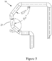
- FIG. 5 shows an enlarged view of the second elbow 16.
- the second elbow 16 comprises a second spool support engaging portion 23.
- the second spool engaging portion 23 is arranged to direct force, generated by the spring 14, onto the spool supply core 6.
- the second spool engaging portion 23 comprises a surface which is arranged at a 6 degree angle to the axis A2 of the spool support when the spring 14 is in a relaxed state. As described above, the angle chosen for the second spool support engaging portion 23 when in a relaxed state may take into account the deformation of the spring 14.
- the angle presented by the second spool support engaging portion 23 to the supply spool core 6 when the spring 14 is deformed is to be generally parallel to the axis A2, such that all of the force directed by the second spool support engaging portion 23 is generally directed radially, perpendicular to the axis A2 of the spool support.
- the angle of the second spool support engaging portion 23 has been offset from 0 degrees to 6 degrees to take into account the deformation of the spring 14. While the specific embodiment shown has a second spool support engaging portion 23 which is arranged at a 6 degree angle to the axis A2 of the spool support, it will be appreciated that other angles may be chosen, dependent, for example, on the particular dimensions and arrangement of the spring 14.
- FIGS. 6 , 7 and 8 there is shown perspective views of the spool support 3 and spring 14, with no supply spool 8 installed on the supply spool support 3.
- the spring 14 is shown in a relaxed state.
- the first spool support engaging portion 19 of the first elbow 15 extends radially through a first aperture 17 in the spool support 3
- the second spool support engaging portion 23 of the second elbow 16 extends radially through a second aperture 18 in the spool support 3.
- the first and second apertures 17, 18 are located at generally opposing sides of the supply spool support 3. Providing the first and second apertures 17, 18 at generally opposing sides allows for a more simple construction of the spring 14, as a planer spring may be used.
- first and second apertures 17, 18 are not located opposite each other. Providing the apertures 17, 18 allows the first and second elbows 15, 16 to radially extend through the first and second apertures 17, 18 so as to engage with a supply spool core 6 when installed on the supply spool support 3 (as shown in Figure 9 ).
- the first aperture 17 is formed between a first stop surface 40 and a second stop surface 41
- the second aperture 18 is formed between a third stop surface 42 and a fourth stop surface 43.
- the stop surfaces 40, 41, 42, 43 are arranged in the rotational path of the first and second elbows 15, 16 so as to provide a limit as to how far the spring 14 can deform rotationally (that is, restrict the torsion that can be applied to the spring 14).
- the first elbow 15 may move circumferentially between the first and second stop surfaces 40, 41
- the second elbow 16 may move circumferentially between the third and fourth stop surfaces 42, 43.
- the first stop surface 40 and the third stop surface are arranged such that when the spring 14 is not subjected to torsion, the first elbow 15 substantially abuts the first stop surface 40 and the second elbow 16 substantially abuts the third stop surface 42. That is, the first and third stop surfaces 40, 42 prevent the first and second elbows 15, 16 moving past the first and third stop surfaces 40, 42. This restricts the deformation that the spring 14 can undergo to only allow deformation from a relaxed state in one direction.
- the direction in which deformation occurs is the direction of rotation of the supply spool 8 when ribbon 7 is unwound from the supply spool core 6, e.g. clockwise.
- the angle over which each aperture 17, 18 extends over the circumferential surface of the supply spool 3 may be any suitable angle.
- the angle may be 15 degrees.
- the angle chosen dictates the maximum compliance provided by spring 14.
- the angle may be chosen so as to provide a compliance in the ribbon path length of around 1-2 mm.
- the angle may be chosen so as to prevent the spring 14 being twisted beyond its elastic limit. As such, the specific value chosen may depend on the material used for the spring 14.
- FIG. 9 there is shown a cross section of a spool support 3 with a supply spool core 6 installed thereon, and shows the spring 14 in a compressed state, e.g. where the first spring action is loaded.
- the first spool support engaging portion 19 of the first elbow 15 engages a first spool core surface 20 of the supply spool core 6.
- the second spool support engaging portion 23 of the second elbow 16 engages a second spool core surface 24 of the supply spool core 6.
- the portion through which the spool core 6 is cut through in Figure 9 shows voids in the spool core 6 (e.g. the unhatched portions). These voids correspond with channels that may run along a portion of the length of the spool core 6, and which may define a series of periodic features 33, described above. Of course, it will be appreciated that such voids are entirely optional.
- the first elbow 15 is configured to direct around 50% of the force outward, perpendicular to the axis A2 and 50% directed distally, parallel to the axis A2 (towards the base 2). This is achieved by directing the force F1 generally 45 degrees from the axis A2 in the distal direction. In an embodiment, this is achieved by arranging the surface of the first spool support engaging portion 19 to be arranged at a substantially 45 degree angle from the axis A2 of the spool support when the spring 14 is in a compressed state.
- the first spool support engaging portion 19 extends through the first aperture 17 and engages the first spool core surface 20 of the supply spool core 6 located at the proximal end of the supply core 6. Additionally, a portion of the first spool support engaging portion 19 lies in the path of removal of the supply spool core 6 (e.g. the path taken to remove the supply spool core 6 from the supply spool support 3). As such, when a user wishes to remove the supply spool core 6, they must apply a force great enough to overcome the component of force directed in the distal direction, and which is also great enough such that the spring 14 is further deformed (e.g. further compressed) during removal such that the first spool support engaging portion 19 does not lie in the path of removal.
- the first spool core surface 20 is arranged at an incline relative to the axis A2 so as to present a surface in a similar plane to the surface of the first spool support engaging portion 19 (e.g. at about 45 degrees from the axis A2 of the spool support 3). Directing the force distally at a 45 degree angle causes a first component of the force F1 to be directed distally so as to retain the supply spool 8 on the supply support 3, and a second component of the force F1 to be directed radially outward. The force F1 also generates friction between the first spool support engaging portion 19 and the first spool core surface 20.
- the first component of the force F1 directed distally also creates friction between a distal portion of the supply spool core 6 and a step 3a of the support spool 3 (shown in Figure 2 ), where the distal portion of the supply spool core 6 abuts the step 3a. That is, friction is generated between the supply spool 8 and a portion of the base 2 (e.g. step 3a).
- the second elbow 16 is configured to direct all of the force F2 imparted by the second elbow 16 generally radially outwards (e.g. perpendicular to the axis A2). In an embodiment, this is achieved by arranging the surface of the second spool support engaging portion 23 to be arranged substantially parallel to the axis A2 of the spool support when the spring 14 is in a compressed state. As can be seen in Figure 9 , the second spool support engaging portion 23 extends through the second aperture 18 engages a second spool core surface 24 of the supply spool core.
- the second spool core surface 24 is an inner cylindrical surface of the supply core whose axis is arranged substantially parallel to the axis A2. The force F2 generates friction between the second spool support engaging portion 23 and the second spool core surface 24 of supply spool core 6.
- the operation of the tapedrive 1 will now be described.
- the operation will relate to an intermittent printing process.
- the printhead 5 is extended so as to be brought into contact with the ribbon 7, allowing the printhead to remove ink from the ribbon and onto a substrate to be printed on as described above.
- the act of extending the printhead 5 and bringing the printhead into contact with the ribbon 7 causes the length of the ribbon path to increase slightly.
- the amount by which the ribbon length increases differs depending on the arrangement of the printer, but is typically in the order of about 1 - 2 mm.
- the increase in ribbon path length causes increased tension in the ribbon, which in turn causes the supply spool 8 to rotate clockwise, removing excess ribbon 7 from the supply spool 8 to make up for the increased ribbon path length.
- the take-up spool support 4 does not substantially rotate to reduce the ribbon tension due to resistance provided by the stationary motor that drives the take up spool support 4.
- the friction generated between the spring 14 and the ribbon core 6 causes the first and second elbows to be angularly displaced in the direction of rotation (e.g. clockwise), elastically deforming the spring 14 so as to generate the second spring action described above. That is, the spring 14 is twisted about the spool rotation axis A2 so as to provide a torque on the ribbon supply spool 3 which resists removal of ribbon 7 from the ribbon supply spool 8.
- the first and second elbows 15, 16 can be said to have been displaced from a first rotational position, as shown in Figure 8a to a second rotational position, as shown in Figure 8b .
- the first and second elbows 15, 16 are shown abutting the second stop surface 41 and fourth stop surface 43 respectively. That is, the elbows 15, 16 have travelled through their maximum angular displacement.
- the angular displacement caused by, for example, the printhead 5 engaging the ribbon 7 may be less than the maximum angular displacement.
- the specific angular displacement of the first and second elbows 15, 16 will depend on a number of factors, such as the magnitude and direction of the various forces involved and the dimensions and materials used. In an example, the elbows 15, 16 may travel through between 5 to 10 degrees when the printhead engages the ribbon 7.
- the length of free ribbon (e.g. not wound onto a spool) is greater than the shortest ribbon path length between the supply spool 8 and take up spool 10.
- the second spring action caused by the twisting of the spring 14, applies a torque on the supply spool core 6 in the anticlockwise direction.
- the supply spool core 6 is rotated in the anticlockwise direction under the influence of the second spring action, taking up excess ribbon 7 that was removed from the supply spool when the printhead 5 was brought into contact with the ink ribbon 7.
- the spring 14 is able to "untwist", releasing the stored energy that was generated when the spring 14 was rotationally deformed. That is, the first and second elbows 15, 16 may return, from the second rotational position, to the first rotational position.
- the spring 14 provides a dancing arm effect which provides a level of compliance in the ribbon path length allowing the supply spool 8 to feed a small length of ribbon 7 into the ribbon path P when the path length P is increased, and take back the small length of ribbon 7 when the path length P is reduced.
- the level of compliance may be 1-2 mm. However, it will be appreciated that other levels of compliance may be used, for example 1-5 mm. It will further be appreciated that the level of compliance will be determined based on the particular materials and configuration used.
Landscapes
- Impression-Transfer Materials And Handling Thereof (AREA)
Abstract
Description
- The present invention relates to a tape drive, and more particularly, but not exclusively, to a tape drive suitable for use in a transfer printer such as a thermal transfer printer.
- Tape drives find a wide variety of uses. One such example is in thermal transfer printers - in which ink is transferred from an ink carrying tape, often referred to as a ribbon - which require a means for transporting the ribbon from a supply spool to a take-up spool past a print head. A tape drive typically comprises two tape spool supports on which spools of tape, such as ink ribbon, may be mounted, and may also include one or more motors for rotating one or both of the spool supports and a controller for operating the motors. In a printing operation, ink carried on the ribbon is transferred to a substrate which is to be printed. To effect the transfer of ink, a print head is brought into contact with the ribbon, and the ribbon is brought into contact with the substrate. The print head contains printing elements which, when heated, whilst in contact with the ribbon, cause ink to be transferred from the ribbon and onto the substrate. Ink will be transferred from regions of the ribbon which are adjacent to printing elements which are heated. An image can be printed on a substrate by selectively heating printing elements which correspond to regions of the image which require ink to be transferred, and not heating printing elements which correspond to regions of the image which require no ink to be transferred. Once the printhead has removed the ink from the ribbon, the print head is removed from the used ribbon, and the ribbon is advanced so as to present unused ribbon to the printhead. The print head is then brought into contact with the unused ribbon as described above.
- It is an object of some embodiments of the present invention to provide an improved tape drive.
- According to a first aspect of the invention there is provided a tape drive. The tape drive comprises a base, a supply spool support extending from the base on which a ribbon supply spool, comprising ink carrying tape, or ribbon, may be installed, the supply spool support being rotationally fixed with respect to the base, the supply spool support defining a spool rotation axis about which the ribbon supply spool may be caused to rotate to allow ribbon to travel along a ribbon path, and a spring. The spring is configured to provide a first spring action, the first spring action configured to generate a braking force by friction and thereby resist relative rotation between the ribbon supply spool and the supply spool support, provide a second spring action configured to provide compliance in a length of the ribbon path during printing.
- Advantageously, the spring provides two functions; i) provides a braking force, e.g. a drag on the rotation of the supply spool, which helps provide ribbon tension in the ribbon during printing, and ii) provides a dancing arm effect by providing compliance in the ribbon path length during printing. Such a spring is particularly useful in low cost printers, as the need to provide a complex braking arrangement or dancing arm arrangement which sits in the ribbon path is obviated.
- Providing compliance in a length of the ribbon path during printing may reduce the risk of ribbon breakage and/or prevent the ribbon from going slack when the ribbon path length changes, such as when a print head engages the ribbon to remove ink from the ribbon onto a substrate.
- The supply spool support may be generally cylindrical, extending along the spool rotation axis. The supply spool support may be integrally formed with the base. The spring may be described as being elastically deformable. That is, the spring will deform under the application of a predefined force, and will return to its original shape following removal of the predefined force.
- The tape drive may comprise a take-up spool support. The take up spool support may be arranged to support a ribbon take-up spool core upon which used ink ribbon is wound following printing.
- The first spring action may be configured to generate the braking force by generating friction between a portion of the spring and a portion of the ribbon supply spool.
- The first spring action may be configured to generate the braking force by generating friction between a portion of the base and a portion of the ribbon supply spool. For example, the first spring action may generate a force which is applied to the supply spool so as to push the portion of the supply spool against a portion of the base.
- The first spring action may be further configured to retain the ribbon supply spool on the spool support. For example, the first spring action may generate a force which is applied to the supply spool so as to resist removal of the supply spool from the supply spool support.
- The supply spool support may comprise the spring. The spring may be housed within the supply spool support.
- The spring may be configured to elastically compress when the ribbon supply spool is installed on the spool support, providing the first spring action.
- For example, when no spool is installed on the supply spool support, the spring may be in a relaxed position. Placement of a spool on the supply spool support may cause the spring to compress, generating the first spring action. The spring may compress along an axis generally perpendicular to the spool rotation axis.
- The spring may be configured to elastically deform about the spool rotation axis so as to provide a torque on the ribbon supply spool which resists removal of ribbon from the ribbon supply spool, providing the second spring action.
- For example, rotation of the ribbon supply spool so as to remove ribbon from the ribbon supply spool may cause the spring to deform in a twisting manner, about the spool rotation axis, providing the second spring action. The elastic deformation about the spool rotation axis may be configured to be caused by the friction between a portion of the spring and a portion of the ribbon supply spool. That is, as the ribbon supply spool rotates, friction between the supply spool and the spring may cause the spring to elastic deform about the spool rotation axis.
- The spring may comprise a first end and a second end, the first end configured to engage a supply spool core of the ribbon supply spool and direct a first force, provided by the spring, on to the supply spool core, and the second end configured to engage the supply spool core and direct a second force, provided by the spring, on to the supply spool core.
- The first and second forces may be generated by the first spring action. The first end and second end may be located at a proximal end of the spring, where a distal end of the spring may be secured to a base portion of the supply spool support or the base plate. The first and second ends may also be referred to as first and second elbows. The magnitude of the first and second forces may be generally be equal. For example, the spring may act between the first and second elbows to provide equal force, in opposite directions, to the first and second ends.
- The first and second ends may be located on generally opposite sides of the spring. Arrangement in this way results in an easier construction method for forming the spring. That is, the spring may be formed in a single plane.
- The spring may be configured to elastically deform about the spool rotation axis when subjected to torque caused by friction between the first end and the supply spool core of the ribbon supply spool, and friction between the second end and the supply spool core of the ribbon supply spool when the ribbon supply spool core rotates.
- That is, the spring may be caused to twist about the spool rotation axis, which loads the second spring action, when subjected to an applied torque caused as the ribbon supply spool is rotated to remove ribbon during ribbon advancement.
- The first and second ends may be configured to be displaced from a first rotational position to a second rotational position when subjected to the torque, so as to elastically deform about the spool rotation axis.
- The first end may be configured to direct the first force on to the spool core at a first angle from the spool rotation axis, and the second end may be configured to direct the second force on to the spool core at a second angle from the spool rotation axis, the first and second angles being different.
- The first angle may be about 45 degrees from the spool rotation axis in a distal direction, and the second angle may be generally perpendicular to the spool rotation axis.
- The spring may be housed within the supply spool support, the supply spool support comprising a first aperture and a second aperture, and wherein the first end is configured to extend through the first aperture, and the second end is configured to extend through the second aperture.
- That is, the spring may be configured such that, when in a relaxed state, the first and second ends extend through the first and second apertures respectively. When a ribbon supply spool is installed on the ribbon supply spool, the first and second ends may engage with the spool core of the ribbon supply spool through the first and second apertures. The first and second apertures may be arranged circumferentially, e.g. on a cylindrical surface of the supply spool support.
- Each of the first and second apertures may subtend an angle of between about 10 to 15 degrees over the circumferential surface of the supply spool support.
- In other implementations, the first and second apertures may subtend an angle of between about 5 to 20 degrees.
- The first and second apertures may be arranged to limit the extent to which the spring can be rotationally deformed about the spool rotation axis.
- For example, the first aperture may be defined by a first surface and a second surface, and the second aperture may be defined by a third surface and a fourth surface. The spring and apertures may be arranged such that when the spring is not deformed about the spool rotation axis (e.g. is not twisted) the first elbow generally abuts the first surface and the second elbow generally abuts the third surface, the first and third surfaces being generally opposite on another, but offset by about the width of the first and second ends such that the first and second ends may abut the first and third surfaces without being substantially deformed. In this way, the direction of rotational deformation is restricted about the spool rotation axis to one rotational direction when starting from a state in which the spring is not rotationally deformed. This particular rotational direction may be opposite the rotational direction travelled by the spool when ribbon is removed from the spool.
- The first, second, third and fourth surfaces may be arranged generally parallel with the spool rotation axis. The surfaces may be arranged in the rotational path of the first and second ends, so as to limit the deformation of the spring. The first, second, third and fourth surfaces may be known as stop surfaces.
- The spring may be configured to provide compliance in the ribbon length of between about 1 to 2 mm.
- In other implementations, the compliance may be between about 1 to 3 mm. In other implementations, the compliance may be between about 1 to 5 mm. It will be appreciated that the compliance required will be specific to the particular tape drive. Other levels of compliance may be used based on the specific circumstances.
- The spring may comprise a foot, the foot being fixed relative to the base of the tape drive.
- The foot may be located at a distal end of the spring. The spring may comprise two feet, both fixed relative to the base of the tape drive. The feet may be opposite the first and second ends.
- The spring may be a substantially planar wire spring.
- The spring may be formed from a single piece.
- A plane of the spring may pass through the spool rotation axis. That is, in an untwisted state, the plane of the spring may pass through the spool rotation axis
- The tape drive may further comprise the ribbon supply spool, the supply spool configured to be installed on the supply spool support. The ribbon supply spool may comprise a spool core and ribbon wound on the spool core.
- In a second aspect there is provided a thermal transfer printer comprising a tape drive according to the first aspect and a printhead arranged to transfer ink from the ribbon to a substrate.
- In a third aspect there is provided a tape spool for being driven by a tape drive according to the first aspect.
- The tape spool may be a supply spool.
- The tape spool may comprise a first spool core surface configured to engage with the first end of the spring, the first spool core surface arranged at an incline relative to the tape spool axis. For example, the incline may be about 45 degrees from the tape spool axis.
- The first spool core surface may be located at an end of the supply core. The first spool core surface may be located at a proximal end of the supply core. That is, an end opposite an end closest to tape drive when the tape spool is installed on a spool support.
- The tape spool may comprise a second spool core surface configured to engage the second end of the spring, the second spool core surface arranged substantially parallel relative to the tape spool axis.
- The second spool core surface may be located on an inner cylindrical surface of the tape spool.
- It will be appreciated that features described in the context of one aspect may be combined with other aspects of the invention.
- Embodiments of the invention will now be described, by way of example, with reference to the accompanying drawings, in which:
-
Figure 1 is a schematic plan illustration of a tape drive in accordance with the present invention; -
Figure 2 is a perspective illustration showing the tape drive ofFigure 1 ; -
Figure 3 is a perspective illustration showing a spring in the form of a wire, the spring in a relaxed state; -
Figure 4 is an enlarged view of a first elbow of the spring ofFigure 3 ; -
Figure 5 is an enlarged view of a second elbow of the spring ofFigure 3 ; -
Figure 6 is an enlarged perspective view of a spool support of the tape drive ofFigure 1 ; -
Figure 7 is a further enlarged perspective view of the spool support ofFigure 6 ; -
Figure 8a is an enlarged plan view of the spool support ofFigure 6 , showing the first and second elbows in a first rotational position; and -
Figure 8b is an enlarged plan view of the spool support ofFigure 6 , showing the first and second elbows in a second rotational position; and -
Figure 9 is a cut away view of the supply spool support ofFigure 6 , showing a spring in a compressed state. - Referring to
Figure 1 , there is illustrated athermal transfer printer 1 having a base plate 2 (sometimes referred to as a base), asupply spool support 3, take-upspool support 4 and aprinthead 5. Thebase plate 2 may, for example, be formed from die-cast metal or moulded plastic. The term 'base plate' may be used to refer to the main component of the body of the printer. It will be understood, however, that the base plate need not be arranged as a single planar component. Indeed the base plate may comprise a plurality of surfaces disposed at various angles relative to one another. Thesupply spool support 3 extends from and is rotationally fixed to the base plate 2 (e.g. cannot rotate relative to the base plate 2). In contrast, the take-upspool support 4 is rotatable relative to thebase plate 2, driven by a motor (not shown). - The terms proximal and distal are used within this specification. The term distal relates to a direction pointing towards the
base plate 2 and the term proximal relates to a direction pointing away from thebase plate 2. - The
supply spool support 3 is arranged to support a ribbonsupply spool core 6, upon which is woundink carrying ribbon 7. Thesupply spool core 6 and anyribbon 7 wound thereon may be referred to as asupply spool 8. While thesupply spool support 3 is fixed with respect to thebase 2, thesupply spool 8 is able to rotate about thesupply spool support 3 when the friction between thesupply spool 8 and thesupply spool support 3 is overcome. Thesupply spool support 3 comprises a spring 14 (seefigure 3 ). Thespring 14 provides a number of functions, which will be described below. - The take-up
spool support 4 is arranged to support a ribbon take-upspool core 9, upon which used ink ribbon is wound following printing. The take-upspool core 9 and any ribbon wound thereon may be referred to as a take-upspool 10. The take-upspool support 4 comprises a retaining means (not shown) for retaining the take-upspool 10 on the take-upspool support 4. This may comprise, for example, a flat spring located on a circumferential surface of the take-upspool support 4, and which projects radially outward when relaxed, and grips an inner circumferential surface of the ribbon take-upspool core 9 when the ribbon take-upspool core 9 is installed on the take-upspool support 4. Theproximal end 4a of the take-upspool support 4 comprises a knurled section for winding ribbon by hand, such as when webbing up withnew ink ribbon 7. - When the motor coupled to the take-up
spool support 4 causes the take-upspool support 4 to rotate in the anti-clockwise direction, theribbon 7 is unwound from thesupply spool 8, causing thesupply spool 8 to rotate clockwise. Theribbon 7 travels along a ribbon path P past theprinthead 5, and is wound on to the take upspool 10. There may be one ormore rollers 13 in the ribbon path P which are used to help guide theribbon 7. One of therollers 13a may be a sticky roller, which may have an encoder for determining ribbon speed. - The
printhead 5 may be any suitable printhead for use in a thermal printer. In an embodiment, theprinthead 5 comprises a printhead ceramic upon which printing elements are arranged in a one-dimensional linear array. Theprinthead 5 further comprises a heatsink, to which the printhead ceramic is attached. The printhead is mounted in aprinthead carriage 11 which is arranged to move linearly, back and forth, along an axis A1 parallel to the direction of travel of theribbon 7. During printing, ink carried on theribbon 7 is transferred to a substrate (not shown) which is to be printed on. To effect the transfer of ink, theprinthead 5 is brought into contact with and pressed against theribbon 7. In the implementation shown in the figures, a printhead in/outdrive assembly 12 is used to move theprinthead 5 to and from theribbon 7. The printhead in/outdrive assembly 12 may be an electromagnetic or pneumatic drive unit. During activation of the in/outdrive assembly 12, theribbon 7 is also brought into contact with the substrate (not shown) to be printed on. The printing elements, when heated, whilst in contact with theribbon 7, cause ink to be transferred from theribbon 7 and onto the substrate to be printed on. Ink will be transferred from regions of theribbon 7 which correspond to (i.e. are aligned with) printing elements which are heated. The array of printing elements can be used to effect printing of an image on to the substrate by selectively heating printing elements which correspond to regions of the image which require ink to be transferred, and not heating printing elements which require no ink to be transferred. Printing a single row of dots on the substrate, parallel to the direction of travel of the printhead, is sometimes referred to as a printing operation. - The
printhead carriage 11 moves along a length (along axis A1) of the substrate so that theprinthead 5 may print along the length of the substrate. That is, a number of printing operations are carried out while the substrate to be printed on is stationary. A total number of printing operations carried out as theprinthead carriage 11 moves along the length of the substrate is sometimes referred to as a printing stroke, where carrying out a printing stroke leads to a plurality of rows of dots being printed on the substrate as theprinthead carriage 11 moves along the length of the substrate. - The operation of the
printer 1 is controlled by a controller (not shown), which is provided on a printed circuit board (not shown). The printed circuit board may be mounted on the reverse side of thebase plate 2. Although, it will be appreciated that the controller may be located elsewhere and coupled to theprinter 1 via a wired or wireless connection. The controller can take any suitable form, including ASICs, FPGAs, or microcontrollers which read and execute instructions stored in a memory to which the controller is connected. - As described above, a motor (not shown) is provided for advancing the
ink ribbon 7 between theribbon supply spool 8 and the ribbon take-upspool 10. A second motor (not shown) is provided for providing the linear movement of theprinthead carriage 11 along axis A1 during printing. The motors may be any suitable motors such as, for example, stepper motors. - Rotation of the supply spool 8 (which, as noted above, is not driven directly) is monitored by a
sensor 32 mounted within the base plate 2 (seeFigures 6 ,7 and8 ). Thesensor 32 sensesperiodic features 33 of thesupply spool core 6, and generates a sensor signal indicative of rotation of thesupply spool 8. For example the sensor signal may comprise a plurality of pulses, each pulse indicating that a predetermined angular rotation has taken place. For example, if 36 periodic features are evenly distributed around the internal surface of thespool core 6 and a pulse is generated as each of the pulses passes thesensor 32, each pulse will indicate that thespool core 6 has rotated by 10 degrees. In the example shown inFigure 1 , theperiodic features 33 are in the form of 10 castellations (not all periodic features are marked in the figure for clarity). - There are generally two modes in which thermal transfer printers can be used, which are sometimes referred to as a "continuous" mode and an "intermittent" mode. In both modes of operation, the apparatus performs a regularly repeated series of printing cycles, each cycle including a printing phase during which ink is transferred to a substrate, and a further non-printing phase during which the printer is prepared for the printing phase of the next cycle.
- In continuous printing, the
print head 5 is brought into contact with theribbon 7, the other side of which is brought into contact with the substrate onto which an image is to be printed. Theprint head 5 is held stationary during this process - the term "stationary" is used in the context of continuous printing to indicate that although the print head will be moved into and out of contact with the ribbon, it will not move relative to the ribbon path in the direction in which ribbon is advanced along that path (e.g. along axis A1). Both the substrate andribbon 7 are transported past the print head, generally but not necessarily at the same speed. - In intermittent printing, a substrate is advanced past the
printhead 5 in a stepwise manner such that during the printing phase of each cycle the substrate and generally but not necessarily theribbon 7 are stationary. Relative movement between the substrate, theribbon 7 and theprinthead 5 are achieved by displacing theprinthead 5 relative to the substrate and ribbon along axis A1. Between the printing phases of successive cycles, the substrate is advanced so as to present the next region to be printed beneath the print head and theribbon 7 is advanced so that an unused section of ribbon is located between theprinthead 5 and the substrate. Accurate transport of theribbon 7 is, therefore, necessary to ensure that unused ribbon is always located between the substrate andprinthead 5 at a time that theprinthead 5 is caused to conduct a printing operation. It will be appreciated that where the intermittent mode is used, theprinthead carriage 11 is caused to move so as to allow its displacement along the ribbon path P (e.g. axis A1). Theprinter 1 is generally used in intermittent mode, but can also be used in continuous mode. - During printing, it is desirable to maintain ribbon tension in the
ribbon 7 in order to avoid ribbon breakage and/or a slack ribbon, for example during ribbon advance or when theprinthead 5 is brought into, and out of, contact theribbon 7. This can be achieved by providing a level of compliance in the length of the ribbon path. A known method of providing compliance is to place a dancing arm in the ribbon path. The dancing arm is able to respond to changes in ribbon tension so as to increase or decrease the ribbon path length, thus providing control of the ribbon tension. It is also desirable to provide a means of retaining thesupply spool 8 on thesupply spool support 3 such that thesupply spool 8 does not come off thesupply spool support 3 during use, but which can be removed if sufficient force is applied, e.g. when a user wishes to remove the supply spool. - According to an embodiment of the present invention, the
supply spool support 3 comprises aspring 14 which is configured to generate a braking force on thesupply spool 8, through friction, which resists relative rotation between thesupply spool 8 and thesupply spool support 3, and provide compliance in a length of the ribbon path during printing (e.g. provide a dancing arm action). Thespring 14 is also configured in an embodiment to retain thesupply spool 8 on thesupply spool support 3. In the example shown in the Figures, the spring comprises a planar wire. A perspective view of thespring 14, depicted in isolation and in a relaxed state, is shown inFigure 3 . Thespring 14 may comprise any resiliently deformable material, such as stainless steel. As can be seen most clearly inFigure 9 , thespring 14 is substantially located within thespool support 3. That is, thespring 14 may be described as being integrated within thespool support 3. - In the embodiment shown, the
spring 14 is configured to retain thesupply spool 8 on thesupply spool support 3 by exerting a force on thesupply spool core 6 which resists removal of thesupply spool core 6 from thesupply spool support 3. Thespring 14 is also configured to generate a frictional force between thespring 14 and thesupply spool core 6. The frictional force provides a braking force (e.g. a drag) which generates ribbon tension during ribbon advancement. Additionally, in response to said frictional force, thespring 14 is configured to elastically deform (e.g. twist) about a supply spool support axis A2 (seeFigure 9 , the supply spool support axis A2 being inline with the spool rotation axis) so as to generate a torque acting on thesupply spool core 6. This torque creates a dancing arm effect which will be described in greater detail below. - At a distal end (an end closest to the base 2) the
spring 14 comprises twofeet 21, which are received withinholes 25 provided at the base of thesupply spool support 3, and act to secure thespring 14 in position. That is, like thesupply spool support 3, thefeet 21 are fixed relative to thebase 2 of thetape drive 1. At a proximal end opposite the distal end, thespring 14 comprises a first end 15 (also referred to herein as a first elbow) and a second end 16 (also referred to herein as a second elbow), which are connected to thefeet 21 via first andsecond legs second elbows feet 21 and can move relative to thefeet 21 through elastic deformation of thespring 14. - The first and
second elbows intermediate portion 28. Theintermediate portion 28 comprises first and secondextended portions second elbows legs intermediate portion 28 also comprises atorsion bar 31 arranged generally perpendicular to the first and secondextended portions extended portions intermediate portion 28, it will be recognised that any suitable form may be used to achieve the desired deformation characteristics. Additionally, It will be appreciated that any number of feet may be used, including one. For example, both the first andsecond elbows - The
spring 14 is configured to provide a first spring action, the first spring action being generated when the first andsecond elbows second elbows supply spool core 6. As such, when thesupply spool core 6 is installed on the spool support 3 (as shown inFigure 9 ), the first andsecond elbows elbows supply spool core 6, as described below, a braking force is generated via friction so as to resist relative rotation between the supply spool and the supply spool support. - The
spring 14 is further configured to provide a second spring action when thespring 14 is subjected to an applied torque. Due to the friction generated between thefirst elbow 15 and thesupply spool core 6, and thesecond elbow 16 and thesupply spool core 6, an applied torque is applied to thespring 14 when the supply spool 8 (and hence the supply spool core 6) is rotated. That is, when thesupply spool 8 is rotated, friction between thesupply spool core 6 and each of the first andsecond elbows spring 14 to elastically deform in a twisting motion about the spool support axis A2, displacing the first andsecond elbows supply spool 8. This deformation provides the second spring action which provides a torque acting on thesupply spool core 6 in an opposite direction to the direction of the applied torque causing the rotation of thesupply spool 8. The first and second spring actions will be described in further detail below. - The first and
second elbows spring 14, to thesupply spool core 6. In particular, it has been found by the inventor that a particular optimal arrangement is one where a greater component of force is directed outward (radially), generally perpendicular to an axis A2 of thespool support 3, than directed distally (towards the base 2), generally parallel to the axis A2. It has further been found to be generally optimal to split the component of force directed by the first elbow such that around 50% of the force is directed perpendicular to the axis A2 and around 50% of the force is directed parallel to the axis A2 (towards thebase 2, .e.g. in the distal direction), and arrange thesecond elbow 16 to direct all of the force directed by thesecond elbow 16 generally perpendicular to the axis A2 (e.g. radially outwards). This split generally allows around 75% of the force generated by thespring 14 to be directed radially outward, and around 25% of the force generated by thespring 14 to be directed towards thebase 2. It should be noted that other arrangements are possible, depending on the desired characteristics of the apparatus. For example, the first and second elbows may be configured so as to each direct 25% of the force distally and 75% of the force radially. In other examples, a different ratio of forces may be used. For example, 60% of the force may be directed distally and 40% may be directed radially. It will be appreciated that the distal component of the force provides both a retaining effect, resisting removal of thesupply spool 8, and pushes thesupply spool core 6 against a portion of thebase 2 causing additional frictional force which provides a braking force (e.g. a drag), generating ribbon tension during ribbon advancement. -
Figure 4 shows an enlarged view of thefirst elbow 15. Thefirst elbow 15 comprises a first spoolsupport engaging portion 19. The firstspool engaging portion 19 is arranged to direct force onto thespool supply core 6, generated by thespring 14. The firstspool engaging portion 19 comprises a surface which is arranged at a 48 degree angle from the axis A2 of the spool support when thespring 14 is in a relaxed state (seeFigure 9 for axis A2). As described above, it is generally preferable to split the force directed by the first spoolsupport engaging portion 19, with roughly 50% of the force imparted by thefirst elbow 15 being directed radially (e.g. perpendicular to the axis A2) and 50% of the force directed distally (e.g. parallel to the axis A2). In order to achieve this split, the first elbow should direct the force distally at an angle of 45 degrees from the axis A2 and onto an upper, or proximal, end of thespool core 6. However, as can be seen inFigure 9 , when thespool core 6 is installed on thespool support 3, thespring 14 is deformed to load the first spring action. By bending theelbows support engaging portion 19 to thesupply spool core 6 is changed from when thespring 14 in a relaxed state. As such, it can be beneficial to offset the angle of the surface of the first spoolsupport engaging portion 19 from the desired angle of 45 degrees to the angle of 48 degrees, such that when thespool core 6 is installed on thespool support 3, the angle presented by the first spoolsupport engaging portion 19 to thesupply spool core 6 is around 45 degrees. In the example shown, the first spoolsupport engaging portion 19 has an angle of 48 degrees. However, it will be appreciated that other angles can be chosen dependent on, for example, the particular dimensions and arrangement of thespring 14. -
Figure 5 shows an enlarged view of thesecond elbow 16. Thesecond elbow 16 comprises a second spoolsupport engaging portion 23. The secondspool engaging portion 23 is arranged to direct force, generated by thespring 14, onto thespool supply core 6. The secondspool engaging portion 23 comprises a surface which is arranged at a 6 degree angle to the axis A2 of the spool support when thespring 14 is in a relaxed state. As described above, the angle chosen for the second spoolsupport engaging portion 23 when in a relaxed state may take into account the deformation of thespring 14. In the present example, the angle presented by the second spoolsupport engaging portion 23 to thesupply spool core 6 when thespring 14 is deformed is to be generally parallel to the axis A2, such that all of the force directed by the second spoolsupport engaging portion 23 is generally directed radially, perpendicular to the axis A2 of the spool support. As such, the angle of the second spoolsupport engaging portion 23 has been offset from 0 degrees to 6 degrees to take into account the deformation of thespring 14. While the specific embodiment shown has a second spoolsupport engaging portion 23 which is arranged at a 6 degree angle to the axis A2 of the spool support, it will be appreciated that other angles may be chosen, dependent, for example, on the particular dimensions and arrangement of thespring 14. - Referring now to
Figures 6 ,7 and8 there is shown perspective views of thespool support 3 andspring 14, with nosupply spool 8 installed on thesupply spool support 3. Thespring 14 is shown in a relaxed state. As can be seen, the first spoolsupport engaging portion 19 of thefirst elbow 15 extends radially through afirst aperture 17 in thespool support 3, and the second spoolsupport engaging portion 23 of thesecond elbow 16 extends radially through asecond aperture 18 in thespool support 3. The first andsecond apertures supply spool support 3. Providing the first andsecond apertures spring 14, as a planer spring may be used. However, it will be appreciated that this may not be required in all embodiments and in some embodiments the first andsecond apertures apertures second elbows second apertures supply spool core 6 when installed on the supply spool support 3 (as shown inFigure 9 ). - As perhaps best shown in
Figures 8a and 8b , thefirst aperture 17 is formed between afirst stop surface 40 and asecond stop surface 41, and thesecond aperture 18 is formed between athird stop surface 42 and afourth stop surface 43. The stop surfaces 40, 41, 42, 43 are arranged in the rotational path of the first andsecond elbows spring 14 can deform rotationally (that is, restrict the torsion that can be applied to the spring 14). In other words, thefirst elbow 15 may move circumferentially between the first and second stop surfaces 40, 41, and thesecond elbow 16 may move circumferentially between the third and fourth stop surfaces 42, 43. - The
first stop surface 40 and the third stop surface are arranged such that when thespring 14 is not subjected to torsion, thefirst elbow 15 substantially abuts thefirst stop surface 40 and thesecond elbow 16 substantially abuts thethird stop surface 42. That is, the first and third stop surfaces 40, 42 prevent the first andsecond elbows spring 14 can undergo to only allow deformation from a relaxed state in one direction. In the present example, the direction in which deformation occurs is the direction of rotation of thesupply spool 8 whenribbon 7 is unwound from thesupply spool core 6, e.g. clockwise. - The angle over which each
aperture supply spool 3 may be any suitable angle. For example, the angle may be 15 degrees. The angle chosen dictates the maximum compliance provided byspring 14. For example, the angle may be chosen so as to provide a compliance in the ribbon path length of around 1-2 mm. Additionally, the angle may be chosen so as to prevent thespring 14 being twisted beyond its elastic limit. As such, the specific value chosen may depend on the material used for thespring 14. - Referring now to
Figure 9 , there is shown a cross section of aspool support 3 with asupply spool core 6 installed thereon, and shows thespring 14 in a compressed state, e.g. where the first spring action is loaded. As can be seen, the first spoolsupport engaging portion 19 of thefirst elbow 15 engages a firstspool core surface 20 of thesupply spool core 6. The second spoolsupport engaging portion 23 of thesecond elbow 16 engages a secondspool core surface 24 of thesupply spool core 6. The portion through which thespool core 6 is cut through inFigure 9 shows voids in the spool core 6 (e.g. the unhatched portions). These voids correspond with channels that may run along a portion of the length of thespool core 6, and which may define a series ofperiodic features 33, described above. Of course, it will be appreciated that such voids are entirely optional. - As described above, the
first elbow 15 is configured to direct around 50% of the force outward, perpendicular to the axis A2 and 50% directed distally, parallel to the axis A2 (towards the base 2). This is achieved by directing the force F1 generally 45 degrees from the axis A2 in the distal direction. In an embodiment, this is achieved by arranging the surface of the first spoolsupport engaging portion 19 to be arranged at a substantially 45 degree angle from the axis A2 of the spool support when thespring 14 is in a compressed state. As can be seen inFigure 9 , the first spoolsupport engaging portion 19 extends through thefirst aperture 17 and engages the firstspool core surface 20 of thesupply spool core 6 located at the proximal end of thesupply core 6. Additionally, a portion of the first spoolsupport engaging portion 19 lies in the path of removal of the supply spool core 6 (e.g. the path taken to remove thesupply spool core 6 from the supply spool support 3). As such, when a user wishes to remove thesupply spool core 6, they must apply a force great enough to overcome the component of force directed in the distal direction, and which is also great enough such that thespring 14 is further deformed (e.g. further compressed) during removal such that the first spoolsupport engaging portion 19 does not lie in the path of removal. - The first
spool core surface 20 is arranged at an incline relative to the axis A2 so as to present a surface in a similar plane to the surface of the first spool support engaging portion 19 (e.g. at about 45 degrees from the axis A2 of the spool support 3). Directing the force distally at a 45 degree angle causes a first component of the force F1 to be directed distally so as to retain thesupply spool 8 on thesupply support 3, and a second component of the force F1 to be directed radially outward. The force F1 also generates friction between the first spoolsupport engaging portion 19 and the firstspool core surface 20. Additionally, the first component of the force F1 directed distally also creates friction between a distal portion of thesupply spool core 6 and astep 3a of the support spool 3 (shown inFigure 2 ), where the distal portion of thesupply spool core 6 abuts thestep 3a. That is, friction is generated between thesupply spool 8 and a portion of the base 2 (e.g. step 3a). - As described above, the
second elbow 16 is configured to direct all of the force F2 imparted by thesecond elbow 16 generally radially outwards (e.g. perpendicular to the axis A2). In an embodiment, this is achieved by arranging the surface of the second spoolsupport engaging portion 23 to be arranged substantially parallel to the axis A2 of the spool support when thespring 14 is in a compressed state. As can be seen inFigure 9 , the second spoolsupport engaging portion 23 extends through thesecond aperture 18 engages a secondspool core surface 24 of the supply spool core. The secondspool core surface 24 is an inner cylindrical surface of the supply core whose axis is arranged substantially parallel to the axis A2. The force F2 generates friction between the second spoolsupport engaging portion 23 and the secondspool core surface 24 ofsupply spool core 6. - The operation of the
tapedrive 1 will now be described. The operation will relate to an intermittent printing process. - During printing, the
printhead 5 is extended so as to be brought into contact with theribbon 7, allowing the printhead to remove ink from the ribbon and onto a substrate to be printed on as described above. The act of extending theprinthead 5 and bringing the printhead into contact with theribbon 7 causes the length of the ribbon path to increase slightly. The amount by which the ribbon length increases differs depending on the arrangement of the printer, but is typically in the order of about 1 - 2 mm. The increase in ribbon path length causes increased tension in the ribbon, which in turn causes thesupply spool 8 to rotate clockwise, removingexcess ribbon 7 from thesupply spool 8 to make up for the increased ribbon path length. It is noted that the take-upspool support 4 does not substantially rotate to reduce the ribbon tension due to resistance provided by the stationary motor that drives the take upspool support 4. - As the
supply spool 8 rotates clockwise in response to the increased ribbon tension, the friction generated between thespring 14 and the ribbon core 6 (e.g. between the first spoolsupport engaging portion 19 and the firstspool core surface 20, and between the second spoolsupport engaging portion 23 and the second spool core surface 24), causes the first and second elbows to be angularly displaced in the direction of rotation (e.g. clockwise), elastically deforming thespring 14 so as to generate the second spring action described above. That is, thespring 14 is twisted about the spool rotation axis A2 so as to provide a torque on theribbon supply spool 3 which resists removal ofribbon 7 from theribbon supply spool 8. The first andsecond elbows Figure 8a to a second rotational position, as shown inFigure 8b . InFigure 8b , the first andsecond elbows second stop surface 41 andfourth stop surface 43 respectively. That is, theelbows printhead 5 engaging theribbon 7 may be less than the maximum angular displacement. The specific angular displacement of the first andsecond elbows elbows ribbon 7. - When the
printhead 5 is subsequently removed from theribbon 7 by retracting theprinthead 5, the length of free ribbon (e.g. not wound onto a spool) is greater than the shortest ribbon path length between thesupply spool 8 and take upspool 10. The second spring action, caused by the twisting of thespring 14, applies a torque on thesupply spool core 6 in the anticlockwise direction. As such, and in response to the reduction in ribbon path length, thesupply spool core 6 is rotated in the anticlockwise direction under the influence of the second spring action, taking upexcess ribbon 7 that was removed from the supply spool when theprinthead 5 was brought into contact with theink ribbon 7. That is, thespring 14 is able to "untwist", releasing the stored energy that was generated when thespring 14 was rotationally deformed. That is, the first andsecond elbows spring 14 provides a dancing arm effect which provides a level of compliance in the ribbon path length allowing thesupply spool 8 to feed a small length ofribbon 7 into the ribbon path P when the path length P is increased, and take back the small length ofribbon 7 when the path length P is reduced. In an embodiment, the level of compliance may be 1-2 mm. However, it will be appreciated that other levels of compliance may be used, for example 1-5 mm. It will further be appreciated that the level of compliance will be determined based on the particular materials and configuration used. - While various embodiments of the invention and variations thereof have been described above, it will be appreciated that various further modifications and variations can be made to the described embodiments without departing from the spirit and scope of the present invention.
- While a specific form of the
spring 14 has been described, e.g. a single piece planer spring, it will be appreciated that other forms may be used to achieve the desired deformation characteristics. Additionally, while a specific form oftape drive 1 has been described, it will be appreciated that other configurations of tape drives may be used. - The described and illustrated embodiments are to be considered as illustrative and not restrictive in character, it being understood that only the preferred embodiments have been shown and described and that all changes and modifications that come within the scope of the inventions as defined in the claims are desired to be protected. In relation to the claims, it is intended that when words such as "a," "an," "at least one," or "at least one portion" are used to preface a feature there is no intention to limit the claim to only one such feature unless specifically stated to the contrary in the claim. When the language "at least a portion" and/or "a portion" is used the item can include a portion and/or the entire item unless specifically stated to the contrary.
Claims (15)
- A tape drive comprising:a base;a supply spool support extending from the base on which a ribbon supply spool may be installed, the supply spool support being rotationally fixed with respect to the base, the supply spool support defining a spool rotation axis about which the ribbon supply spool may be caused to rotate to allow ribbon to travel along a ribbon path;a spring configured to:provide a first spring action, the first spring action configured to generate a braking force by friction and thereby resist relative rotation between the ribbon supply spool and the supply spool support, the first spring action further configured to retain the ribbon supply spool on the spool support;provide a second spring action configured to provide compliance in a length of the ribbon path during printing.
- The tape drive of claim 1, wherein, the first spring action is configured to generate the braking force by generating friction between a portion of the spring and a portion of the ribbon supply spool.
- The tape drive of claim 1 or 2, wherein the first spring action is configured to generate the braking force by generating friction between a portion of the base and a portion of the ribbon supply spool.
- The tape drive as in any preceding claim, wherein the supply spool support comprises the spring and/or, wherein the spring is configured to elastically compress when the ribbon supply spool is installed on the supply spool support, providing the first spring action.
- The tape drive as in any preceding claim, wherein the spring configured to elastically deform about the spool rotation axis so as to provide a torque on the ribbon supply spool which resists removal of ribbon from the ribbon supply spool, providing the second spring action.
- The tape drive of any preceding claim, wherein the spring comprises a first end and a second end;
the first end configured to engage a spool core of the ribbon supply spool and direct a first force, provided by the spring, on to the spool core;
the second end configured to engage the spool core and direct a second force, provided by the spring, on to the spool core and optionally, wherein the first and second ends are located on generally opposite sides of the spring. - The tape drive of claim 6, wherein the spring is configured to elastically deform about the spool rotation axis when subjected to torque caused by friction between the first end and spool core of the ribbon supply spool, and friction between the second end and spool core of the ribbon supply spool when the spool core rotates, and optionally, wherein the first and second ends are configured to be displaced from a first rotational position to a second rotational position when subjected to the torque, so as to elastically deform about the spool rotation axis.
- The tape drive of any one of claims 6 to 7, wherein:the first end is configured to direct the first force on to the spool core at a first angle from the spool rotation axis;the second end is configured to direct the second force on to the spool core at a second angle from the spool rotation axis, the first and second angles being different and optionally, wherein the first angle is about 45 degrees from the spool rotation axis in a distal direction;the second angle is generally perpendicular to the spool rotation axis.
- The tape drive of any one of claims 6 to 8, wherein the spring is housed within the supply spool support, the supply spool support comprising a first aperture and a second aperture, and wherein:the first end is configured to extend through the first aperture; andthe second end is configured to extend through the second aperture.
- The tape drive of claim 9, wherein the each of the first and second apertures subtend an angle of between about 10 to 15 degrees over the circumferential surface of the supply spool support.
- The tape drive of any one of claims 9 or 10, wherein the first and second apertures are arranged to limit the extent to which the spring can be rotationally deformed about the spool rotation axis.
- The tape drive of any preceding claim, wherein the spring is configured to provide compliance in the ribbon length of between about 1 to 2 mm.
- The tape drive of any preceding claim, the spring comprising a foot, the foot being fixed relative to the base of the tape drive, and/or, wherein the spring is a substantially planar wire spring, and/or, wherein the spring is formed from a single piece, and/or, a plane of the spring passes through the spool rotation axis and/or, further comprising the ribbon supply spool, the ribbon supply spool configured to be installed on the supply spool support.
- A thermal transfer printer comprising:a tape drive according to any one of claims 1 to 13; anda printhead arranged to transfer ink from ribbon to a substrate.
- A tape spool for being driven by a tape drive according to any preceding claim.
Applications Claiming Priority (1)
| Application Number | Priority Date | Filing Date | Title |
|---|---|---|---|
| GBGB2001041.9A GB202001041D0 (en) | 2020-01-24 | 2020-01-24 | Tape drive |
Publications (2)
| Publication Number | Publication Date |
|---|---|
| EP3854597A1 true EP3854597A1 (en) | 2021-07-28 |
| EP3854597B1 EP3854597B1 (en) | 2024-06-12 |
Family
ID=69725875
Family Applications (1)
| Application Number | Title | Priority Date | Filing Date |
|---|---|---|---|
| EP20208493.5A Active EP3854597B1 (en) | 2020-01-24 | 2020-11-18 | Tape drive |
Country Status (4)
| Country | Link |
|---|---|
| EP (1) | EP3854597B1 (en) |
| CN (1) | CN113173009B (en) |
| BR (1) | BR102020023449A2 (en) |
| GB (1) | GB202001041D0 (en) |
Families Citing this family (2)
| Publication number | Priority date | Publication date | Assignee | Title |
|---|---|---|---|---|
| USD1095667S1 (en) * | 2021-09-27 | 2025-09-30 | Videojet Technologies Inc. | Thermal transfer printer |
| USD1098256S1 (en) * | 2021-09-27 | 2025-10-14 | Videojet Technologies Inc. | Thermal transfer printer |
Citations (3)
| Publication number | Priority date | Publication date | Assignee | Title |
|---|---|---|---|---|
| EP0410259A1 (en) * | 1989-07-17 | 1991-01-30 | Kroy Inc. | Thermal printing apparatus and tape supply cartridge therefor |
| US9670028B1 (en) * | 2010-10-27 | 2017-06-06 | Philo Jefferson Pinto | Trigger operated brake for handheld tape dispenser including a barbed spool holder |
| US20190009596A1 (en) * | 2015-07-31 | 2019-01-10 | Videojet Technologies Inc. | Tape drive and associated spool |
Family Cites Families (1)
| Publication number | Priority date | Publication date | Assignee | Title |
|---|---|---|---|---|
| JP3610158B2 (en) * | 1996-04-05 | 2005-01-12 | セイコーエプソン株式会社 | Tape reel device and tape cartridge provided with the same |
-
2020
- 2020-01-24 GB GBGB2001041.9A patent/GB202001041D0/en not_active Ceased
- 2020-11-17 BR BR102020023449-8A patent/BR102020023449A2/en unknown
- 2020-11-18 EP EP20208493.5A patent/EP3854597B1/en active Active
- 2020-11-30 CN CN202011370236.6A patent/CN113173009B/en active Active
Patent Citations (3)
| Publication number | Priority date | Publication date | Assignee | Title |
|---|---|---|---|---|
| EP0410259A1 (en) * | 1989-07-17 | 1991-01-30 | Kroy Inc. | Thermal printing apparatus and tape supply cartridge therefor |
| US9670028B1 (en) * | 2010-10-27 | 2017-06-06 | Philo Jefferson Pinto | Trigger operated brake for handheld tape dispenser including a barbed spool holder |
| US20190009596A1 (en) * | 2015-07-31 | 2019-01-10 | Videojet Technologies Inc. | Tape drive and associated spool |
Also Published As
| Publication number | Publication date |
|---|---|
| GB202001041D0 (en) | 2020-03-11 |
| EP3854597B1 (en) | 2024-06-12 |
| CN113173009A (en) | 2021-07-27 |
| CN113173009B (en) | 2022-10-04 |
| BR102020023449A2 (en) | 2022-02-22 |
Similar Documents
| Publication | Publication Date | Title |
|---|---|---|
| EP3854597B1 (en) | Tape drive | |
| US4577198A (en) | Thermal transfer printer | |
| EP2036845B1 (en) | Mounting assembly and method of loading and/or unloading rolls | |
| US8857973B2 (en) | Sheet conveying device and recording apparatus | |
| US4502801A (en) | Ribbon cassette for word processors, printers and typewriters | |
| GB2033340A (en) | Web cartridges | |
| JP2018122504A (en) | Printer, printing method and printing program | |
| CN100503260C (en) | Printer | |
| US6042039A (en) | Tape reel device with brake mechanism applying constant back tension | |
| KR870001991Y1 (en) | Tape feeding apparatus | |
| JPH0239400B2 (en) | ||
| JPS6135983A (en) | Multicolor printer | |
| US20070291100A1 (en) | Print head assmebly and method used with image forming apparatus | |
| JPS5912472B2 (en) | printing device | |
| US4160606A (en) | Paper feed mechanism for multiple copy printer | |
| JPS6021285A (en) | Ribbon cartridge | |
| JP7643011B2 (en) | Printing device and method for controlling printing device | |
| US4591882A (en) | Printer electromagnetic clutch drive | |
| JPS6222374Y2 (en) | ||
| JP7471850B2 (en) | Recording apparatus and transport method | |
| JPH0443518B2 (en) | ||
| US4798487A (en) | Thermal printer having ribbon take-up mechanism utilizing carriage movement | |
| US4838716A (en) | Ribbon cartridge for a printer | |
| WO1999046129A2 (en) | Flat-bed thermal printer with ribbon gripping means | |
| JPH0443519B2 (en) |
Legal Events
| Date | Code | Title | Description |
|---|---|---|---|
| PUAI | Public reference made under article 153(3) epc to a published international application that has entered the european phase |
Free format text: ORIGINAL CODE: 0009012 |
|
| STAA | Information on the status of an ep patent application or granted ep patent |
Free format text: STATUS: REQUEST FOR EXAMINATION WAS MADE |
|
| 17P | Request for examination filed |
Effective date: 20201118 |
|
| AK | Designated contracting states |
Kind code of ref document: A1 Designated state(s): AL AT BE BG CH CY CZ DE DK EE ES FI FR GB GR HR HU IE IS IT LI LT LU LV MC MK MT NL NO PL PT RO RS SE SI SK SM TR |
|
| GRAP | Despatch of communication of intention to grant a patent |
Free format text: ORIGINAL CODE: EPIDOSNIGR1 |
|
| STAA | Information on the status of an ep patent application or granted ep patent |
Free format text: STATUS: GRANT OF PATENT IS INTENDED |
|
| P01 | Opt-out of the competence of the unified patent court (upc) registered |
Effective date: 20230530 |
|
| INTG | Intention to grant announced |
Effective date: 20230623 |
|
| GRAJ | Information related to disapproval of communication of intention to grant by the applicant or resumption of examination proceedings by the epo deleted |
Free format text: ORIGINAL CODE: EPIDOSDIGR1 |
|
| STAA | Information on the status of an ep patent application or granted ep patent |
Free format text: STATUS: REQUEST FOR EXAMINATION WAS MADE |
|
| INTC | Intention to grant announced (deleted) | ||
| GRAP | Despatch of communication of intention to grant a patent |
Free format text: ORIGINAL CODE: EPIDOSNIGR1 |
|
| STAA | Information on the status of an ep patent application or granted ep patent |
Free format text: STATUS: GRANT OF PATENT IS INTENDED |
|
| INTG | Intention to grant announced |
Effective date: 20231222 |
|
| INTG | Intention to grant announced |
Effective date: 20240108 |
|
| GRAS | Grant fee paid |
Free format text: ORIGINAL CODE: EPIDOSNIGR3 |
|
| GRAA | (expected) grant |
Free format text: ORIGINAL CODE: 0009210 |
|
| STAA | Information on the status of an ep patent application or granted ep patent |
Free format text: STATUS: THE PATENT HAS BEEN GRANTED |
|
| AK | Designated contracting states |
Kind code of ref document: B1 Designated state(s): AL AT BE BG CH CY CZ DE DK EE ES FI FR GB GR HR HU IE IS IT LI LT LU LV MC MK MT NL NO PL PT RO RS SE SI SK SM TR |
|
| REG | Reference to a national code |
Ref country code: GB Ref legal event code: FG4D |
|
| REG | Reference to a national code |
Ref country code: CH Ref legal event code: EP |
|
| REG | Reference to a national code |
Ref country code: DE Ref legal event code: R096 Ref document number: 602020032236 Country of ref document: DE |
|
| REG | Reference to a national code |
Ref country code: IE Ref legal event code: FG4D |
|
| PG25 | Lapsed in a contracting state [announced via postgrant information from national office to epo] |
Ref country code: BG Free format text: LAPSE BECAUSE OF FAILURE TO SUBMIT A TRANSLATION OF THE DESCRIPTION OR TO PAY THE FEE WITHIN THE PRESCRIBED TIME-LIMIT Effective date: 20240612 |
|
| PG25 | Lapsed in a contracting state [announced via postgrant information from national office to epo] |
Ref country code: FI Free format text: LAPSE BECAUSE OF FAILURE TO SUBMIT A TRANSLATION OF THE DESCRIPTION OR TO PAY THE FEE WITHIN THE PRESCRIBED TIME-LIMIT Effective date: 20240612 Ref country code: HR Free format text: LAPSE BECAUSE OF FAILURE TO SUBMIT A TRANSLATION OF THE DESCRIPTION OR TO PAY THE FEE WITHIN THE PRESCRIBED TIME-LIMIT Effective date: 20240612 |
|
| REG | Reference to a national code |
Ref country code: LT Ref legal event code: MG9D |
|
| PG25 | Lapsed in a contracting state [announced via postgrant information from national office to epo] |
Ref country code: GR Free format text: LAPSE BECAUSE OF FAILURE TO SUBMIT A TRANSLATION OF THE DESCRIPTION OR TO PAY THE FEE WITHIN THE PRESCRIBED TIME-LIMIT Effective date: 20240913 |
|
| REG | Reference to a national code |
Ref country code: NL Ref legal event code: MP Effective date: 20240612 |
|
| PG25 | Lapsed in a contracting state [announced via postgrant information from national office to epo] |
Ref country code: ES Free format text: LAPSE BECAUSE OF FAILURE TO SUBMIT A TRANSLATION OF THE DESCRIPTION OR TO PAY THE FEE WITHIN THE PRESCRIBED TIME-LIMIT Effective date: 20240612 |
|
| PG25 | Lapsed in a contracting state [announced via postgrant information from national office to epo] |
Ref country code: LV Free format text: LAPSE BECAUSE OF FAILURE TO SUBMIT A TRANSLATION OF THE DESCRIPTION OR TO PAY THE FEE WITHIN THE PRESCRIBED TIME-LIMIT Effective date: 20240612 |
|
| PG25 | Lapsed in a contracting state [announced via postgrant information from national office to epo] |
Ref country code: NO Free format text: LAPSE BECAUSE OF FAILURE TO SUBMIT A TRANSLATION OF THE DESCRIPTION OR TO PAY THE FEE WITHIN THE PRESCRIBED TIME-LIMIT Effective date: 20240912 Ref country code: LV Free format text: LAPSE BECAUSE OF FAILURE TO SUBMIT A TRANSLATION OF THE DESCRIPTION OR TO PAY THE FEE WITHIN THE PRESCRIBED TIME-LIMIT Effective date: 20240612 Ref country code: HR Free format text: LAPSE BECAUSE OF FAILURE TO SUBMIT A TRANSLATION OF THE DESCRIPTION OR TO PAY THE FEE WITHIN THE PRESCRIBED TIME-LIMIT Effective date: 20240612 Ref country code: GR Free format text: LAPSE BECAUSE OF FAILURE TO SUBMIT A TRANSLATION OF THE DESCRIPTION OR TO PAY THE FEE WITHIN THE PRESCRIBED TIME-LIMIT Effective date: 20240913 Ref country code: FI Free format text: LAPSE BECAUSE OF FAILURE TO SUBMIT A TRANSLATION OF THE DESCRIPTION OR TO PAY THE FEE WITHIN THE PRESCRIBED TIME-LIMIT Effective date: 20240612 Ref country code: ES Free format text: LAPSE BECAUSE OF FAILURE TO SUBMIT A TRANSLATION OF THE DESCRIPTION OR TO PAY THE FEE WITHIN THE PRESCRIBED TIME-LIMIT Effective date: 20240612 Ref country code: BG Free format text: LAPSE BECAUSE OF FAILURE TO SUBMIT A TRANSLATION OF THE DESCRIPTION OR TO PAY THE FEE WITHIN THE PRESCRIBED TIME-LIMIT Effective date: 20240612 Ref country code: RS Free format text: LAPSE BECAUSE OF FAILURE TO SUBMIT A TRANSLATION OF THE DESCRIPTION OR TO PAY THE FEE WITHIN THE PRESCRIBED TIME-LIMIT Effective date: 20240912 |
|
| PG25 | Lapsed in a contracting state [announced via postgrant information from national office to epo] |
Ref country code: NL Free format text: LAPSE BECAUSE OF FAILURE TO SUBMIT A TRANSLATION OF THE DESCRIPTION OR TO PAY THE FEE WITHIN THE PRESCRIBED TIME-LIMIT Effective date: 20240612 |
|
| REG | Reference to a national code |
Ref country code: AT Ref legal event code: MK05 Ref document number: 1693912 Country of ref document: AT Kind code of ref document: T Effective date: 20240612 |
|
| PG25 | Lapsed in a contracting state [announced via postgrant information from national office to epo] |
Ref country code: NL Free format text: LAPSE BECAUSE OF FAILURE TO SUBMIT A TRANSLATION OF THE DESCRIPTION OR TO PAY THE FEE WITHIN THE PRESCRIBED TIME-LIMIT Effective date: 20240612 |
|
| PG25 | Lapsed in a contracting state [announced via postgrant information from national office to epo] |
Ref country code: PT Free format text: LAPSE BECAUSE OF FAILURE TO SUBMIT A TRANSLATION OF THE DESCRIPTION OR TO PAY THE FEE WITHIN THE PRESCRIBED TIME-LIMIT Effective date: 20241014 |
|
| PG25 | Lapsed in a contracting state [announced via postgrant information from national office to epo] |
Ref country code: PT Free format text: LAPSE BECAUSE OF FAILURE TO SUBMIT A TRANSLATION OF THE DESCRIPTION OR TO PAY THE FEE WITHIN THE PRESCRIBED TIME-LIMIT Effective date: 20241014 |
|
| PG25 | Lapsed in a contracting state [announced via postgrant information from national office to epo] |
Ref country code: PL Free format text: LAPSE BECAUSE OF FAILURE TO SUBMIT A TRANSLATION OF THE DESCRIPTION OR TO PAY THE FEE WITHIN THE PRESCRIBED TIME-LIMIT Effective date: 20240612 |
|
| PG25 | Lapsed in a contracting state [announced via postgrant information from national office to epo] |
Ref country code: EE Free format text: LAPSE BECAUSE OF FAILURE TO SUBMIT A TRANSLATION OF THE DESCRIPTION OR TO PAY THE FEE WITHIN THE PRESCRIBED TIME-LIMIT Effective date: 20240612 |
|
| PG25 | Lapsed in a contracting state [announced via postgrant information from national office to epo] |
Ref country code: AT Free format text: LAPSE BECAUSE OF FAILURE TO SUBMIT A TRANSLATION OF THE DESCRIPTION OR TO PAY THE FEE WITHIN THE PRESCRIBED TIME-LIMIT Effective date: 20240612 Ref country code: IS Free format text: LAPSE BECAUSE OF FAILURE TO SUBMIT A TRANSLATION OF THE DESCRIPTION OR TO PAY THE FEE WITHIN THE PRESCRIBED TIME-LIMIT Effective date: 20241012 |
|
| PG25 | Lapsed in a contracting state [announced via postgrant information from national office to epo] |
Ref country code: CZ Free format text: LAPSE BECAUSE OF FAILURE TO SUBMIT A TRANSLATION OF THE DESCRIPTION OR TO PAY THE FEE WITHIN THE PRESCRIBED TIME-LIMIT Effective date: 20240612 |
|
| PG25 | Lapsed in a contracting state [announced via postgrant information from national office to epo] |
Ref country code: RO Free format text: LAPSE BECAUSE OF FAILURE TO SUBMIT A TRANSLATION OF THE DESCRIPTION OR TO PAY THE FEE WITHIN THE PRESCRIBED TIME-LIMIT Effective date: 20240612 Ref country code: SK Free format text: LAPSE BECAUSE OF FAILURE TO SUBMIT A TRANSLATION OF THE DESCRIPTION OR TO PAY THE FEE WITHIN THE PRESCRIBED TIME-LIMIT Effective date: 20240612 |
|
| PG25 | Lapsed in a contracting state [announced via postgrant information from national office to epo] |
Ref country code: SM Free format text: LAPSE BECAUSE OF FAILURE TO SUBMIT A TRANSLATION OF THE DESCRIPTION OR TO PAY THE FEE WITHIN THE PRESCRIBED TIME-LIMIT Effective date: 20240612 |
|
| PG25 | Lapsed in a contracting state [announced via postgrant information from national office to epo] |
Ref country code: SM Free format text: LAPSE BECAUSE OF FAILURE TO SUBMIT A TRANSLATION OF THE DESCRIPTION OR TO PAY THE FEE WITHIN THE PRESCRIBED TIME-LIMIT Effective date: 20240612 Ref country code: SK Free format text: LAPSE BECAUSE OF FAILURE TO SUBMIT A TRANSLATION OF THE DESCRIPTION OR TO PAY THE FEE WITHIN THE PRESCRIBED TIME-LIMIT Effective date: 20240612 Ref country code: RO Free format text: LAPSE BECAUSE OF FAILURE TO SUBMIT A TRANSLATION OF THE DESCRIPTION OR TO PAY THE FEE WITHIN THE PRESCRIBED TIME-LIMIT Effective date: 20240612 Ref country code: PL Free format text: LAPSE BECAUSE OF FAILURE TO SUBMIT A TRANSLATION OF THE DESCRIPTION OR TO PAY THE FEE WITHIN THE PRESCRIBED TIME-LIMIT Effective date: 20240612 Ref country code: IS Free format text: LAPSE BECAUSE OF FAILURE TO SUBMIT A TRANSLATION OF THE DESCRIPTION OR TO PAY THE FEE WITHIN THE PRESCRIBED TIME-LIMIT Effective date: 20241012 Ref country code: EE Free format text: LAPSE BECAUSE OF FAILURE TO SUBMIT A TRANSLATION OF THE DESCRIPTION OR TO PAY THE FEE WITHIN THE PRESCRIBED TIME-LIMIT Effective date: 20240612 Ref country code: CZ Free format text: LAPSE BECAUSE OF FAILURE TO SUBMIT A TRANSLATION OF THE DESCRIPTION OR TO PAY THE FEE WITHIN THE PRESCRIBED TIME-LIMIT Effective date: 20240612 Ref country code: AT Free format text: LAPSE BECAUSE OF FAILURE TO SUBMIT A TRANSLATION OF THE DESCRIPTION OR TO PAY THE FEE WITHIN THE PRESCRIBED TIME-LIMIT Effective date: 20240612 |
|
| PG25 | Lapsed in a contracting state [announced via postgrant information from national office to epo] |
Ref country code: IT Free format text: LAPSE BECAUSE OF FAILURE TO SUBMIT A TRANSLATION OF THE DESCRIPTION OR TO PAY THE FEE WITHIN THE PRESCRIBED TIME-LIMIT Effective date: 20240612 |
|
| REG | Reference to a national code |
Ref country code: DE Ref legal event code: R097 Ref document number: 602020032236 Country of ref document: DE |
|
| PG25 | Lapsed in a contracting state [announced via postgrant information from national office to epo] |
Ref country code: DK Free format text: LAPSE BECAUSE OF FAILURE TO SUBMIT A TRANSLATION OF THE DESCRIPTION OR TO PAY THE FEE WITHIN THE PRESCRIBED TIME-LIMIT Effective date: 20240612 |
|
| PLBE | No opposition filed within time limit |
Free format text: ORIGINAL CODE: 0009261 |
|
| STAA | Information on the status of an ep patent application or granted ep patent |
Free format text: STATUS: NO OPPOSITION FILED WITHIN TIME LIMIT |
|
| 26N | No opposition filed |
Effective date: 20250313 |
|
| REG | Reference to a national code |
Ref country code: DE Ref legal event code: R119 Ref document number: 602020032236 Country of ref document: DE |
|
| REG | Reference to a national code |
Ref country code: CH Ref legal event code: PL |
|
| PG25 | Lapsed in a contracting state [announced via postgrant information from national office to epo] |
Ref country code: MC Free format text: LAPSE BECAUSE OF FAILURE TO SUBMIT A TRANSLATION OF THE DESCRIPTION OR TO PAY THE FEE WITHIN THE PRESCRIBED TIME-LIMIT Effective date: 20240612 |
|
| PG25 | Lapsed in a contracting state [announced via postgrant information from national office to epo] |
Ref country code: LU Free format text: LAPSE BECAUSE OF NON-PAYMENT OF DUE FEES Effective date: 20241118 |
|
| REG | Reference to a national code |
Ref country code: CH Ref legal event code: PL |
|
| PG25 | Lapsed in a contracting state [announced via postgrant information from national office to epo] |
Ref country code: CH Free format text: LAPSE BECAUSE OF NON-PAYMENT OF DUE FEES Effective date: 20241130 |
|
| REG | Reference to a national code |
Ref country code: BE Ref legal event code: MM Effective date: 20241130 |
|
| PG25 | Lapsed in a contracting state [announced via postgrant information from national office to epo] |
Ref country code: SE Free format text: LAPSE BECAUSE OF FAILURE TO SUBMIT A TRANSLATION OF THE DESCRIPTION OR TO PAY THE FEE WITHIN THE PRESCRIBED TIME-LIMIT Effective date: 20240612 |
|
| PG25 | Lapsed in a contracting state [announced via postgrant information from national office to epo] |
Ref country code: DE Free format text: LAPSE BECAUSE OF NON-PAYMENT OF DUE FEES Effective date: 20250603 |
|
| PG25 | Lapsed in a contracting state [announced via postgrant information from national office to epo] |
Ref country code: BE Free format text: LAPSE BECAUSE OF NON-PAYMENT OF DUE FEES Effective date: 20241130 |
|
| PG25 | Lapsed in a contracting state [announced via postgrant information from national office to epo] |
Ref country code: FR Free format text: LAPSE BECAUSE OF NON-PAYMENT OF DUE FEES Effective date: 20241130 |
|
| PG25 | Lapsed in a contracting state [announced via postgrant information from national office to epo] |
Ref country code: IE Free format text: LAPSE BECAUSE OF NON-PAYMENT OF DUE FEES Effective date: 20241118 |
|
| PGFP | Annual fee paid to national office [announced via postgrant information from national office to epo] |
Ref country code: GB Payment date: 20251121 Year of fee payment: 6 |
|
| PG25 | Lapsed in a contracting state [announced via postgrant information from national office to epo] |
Ref country code: HU Free format text: LAPSE BECAUSE OF FAILURE TO SUBMIT A TRANSLATION OF THE DESCRIPTION OR TO PAY THE FEE WITHIN THE PRESCRIBED TIME-LIMIT; INVALID AB INITIO Effective date: 20201118 |
|
| PG25 | Lapsed in a contracting state [announced via postgrant information from national office to epo] |
Ref country code: CY Free format text: LAPSE BECAUSE OF FAILURE TO SUBMIT A TRANSLATION OF THE DESCRIPTION OR TO PAY THE FEE WITHIN THE PRESCRIBED TIME-LIMIT; INVALID AB INITIO Effective date: 20201118 |