EP3854551A1 - A device for manufacturing from a sheet of packaging material membranes for capsules of a beverage, such capsules adapted to contain an anhydrous material - Google Patents
A device for manufacturing from a sheet of packaging material membranes for capsules of a beverage, such capsules adapted to contain an anhydrous material Download PDFInfo
- Publication number
- EP3854551A1 EP3854551A1 EP21153089.4A EP21153089A EP3854551A1 EP 3854551 A1 EP3854551 A1 EP 3854551A1 EP 21153089 A EP21153089 A EP 21153089A EP 3854551 A1 EP3854551 A1 EP 3854551A1
- Authority
- EP
- European Patent Office
- Prior art keywords
- axis
- frustoconical
- cutting
- groove
- coaxially
- Prior art date
- Legal status (The legal status is an assumption and is not a legal conclusion. Google has not performed a legal analysis and makes no representation as to the accuracy of the status listed.)
- Granted
Links
Images



Classifications
-
- B—PERFORMING OPERATIONS; TRANSPORTING
- B26—HAND CUTTING TOOLS; CUTTING; SEVERING
- B26F—PERFORATING; PUNCHING; CUTTING-OUT; STAMPING-OUT; SEVERING BY MEANS OTHER THAN CUTTING
- B26F1/00—Perforating; Punching; Cutting-out; Stamping-out; Apparatus therefor
- B26F1/38—Cutting-out; Stamping-out
- B26F1/44—Cutters therefor; Dies therefor
-
- B—PERFORMING OPERATIONS; TRANSPORTING
- B26—HAND CUTTING TOOLS; CUTTING; SEVERING
- B26F—PERFORATING; PUNCHING; CUTTING-OUT; STAMPING-OUT; SEVERING BY MEANS OTHER THAN CUTTING
- B26F1/00—Perforating; Punching; Cutting-out; Stamping-out; Apparatus therefor
- B26F1/38—Cutting-out; Stamping-out
- B26F1/3846—Cutting-out; Stamping-out cutting out discs or the like
-
- B—PERFORMING OPERATIONS; TRANSPORTING
- B26—HAND CUTTING TOOLS; CUTTING; SEVERING
- B26F—PERFORATING; PUNCHING; CUTTING-OUT; STAMPING-OUT; SEVERING BY MEANS OTHER THAN CUTTING
- B26F1/00—Perforating; Punching; Cutting-out; Stamping-out; Apparatus therefor
- B26F1/38—Cutting-out; Stamping-out
- B26F1/44—Cutters therefor; Dies therefor
- B26F2001/4472—Cutting edge section features
Definitions
- the present invention relates to a device for manufacturing membranes for capsules adapted to contain an anhydrous material for the production of a beverage, in particular anhydrous material in the form of powder, grains or leaves, such as coffee, tea, barley, cocoa, or the like, starting from a sheet of packaging material, in particular a sheet of malleable material, for example aluminium.
- anhydrous material in the form of powder, grains or leaves, such as coffee, tea, barley, cocoa, or the like, starting from a sheet of packaging material, in particular a sheet of malleable material, for example aluminium.
- anhydrous material contained in a capsule in particular an anhydrous material in the form of powder, grains or leaves, for example coffee, tea, barley, or the like.
- the capsules intended to contain the above-mentioned anhydrous material are produced in generally automated, manufacturing and assembly plants and comprise a hollow cup-shaped body, which is open at the top and has a substantially frustoconical shape.
- the cup-shaped body generally has an axis of symmetry and comprises a base, arranged at a lower axial end of the cup-shaped body, and a flange, which extends radially outwards from an upper axial end of the cup-shaped body.
- the upper end has a larger diameter than the lower end
- the flange has a substantially annular shape and is formed integrally with the cup-shaped body at the upper end.
- the cup-shaped body defines, coaxially inside it, a cavity which is open at the top and is intended to house, in use, the anhydrous material, which is pressed for optimum use of the internal space of the cavity itself.
- the cavity has such dimensions that the cup-shaped body can be considered a thin-walled body.
- Capsules of the type described above also comprise a membrane made starting from a sheet of packaging material, in particular a sheet of malleable material, for example aluminium, and configured to close the cup-shaped body at the top.
- the membrane is typically circular in shape and is attached to the cup-shaped body at the upper end thereof.
- the aforesaid cavity is closed by applying the membrane on the upper surface of the annular flange.
- the capsules of the type described above, once assembled, are intended to be used in extractor machines that produce a generally single-serve beverage, starting from a single capsule, according to a known method that is not described in detail.
- the membrane is applied to the annular flange in an automated manner in the aforesaid manufacturing and assembly plants, by using specific glues or adhesive materials or by welding, so that it adheres to the upper surface of the annular flange.
- the membrane is manually applied to the annular flange using a portable manual capsule assembly device starting from a cup-shaped body and a membrane made of packaging material.
- a known system involves the use of a die.
- the object of this invention is thus to obtain a device for manufacturing membranes for capsules adapted to contain an anhydrous material starting from a sheet of packaging material, which is very reliable and inexpensive and which satisfies the above-specified requirement related to capsule membrane manufacturing devices of a known type.
- the reference number 1 represents, as a whole, a device for manufacturing membranes 2 for capsules 3 adapted to contain an anhydrous material for the production of a beverage, in particular anhydrous material in the form of powder, grains or leaves, such as coffee, tea, barley, cocoa, or the like, starting from a sheet 4 of packaging material, in particular a sheet 4 of malleable material, for example aluminium.
- the capsules 3 are intended for use in extractor machines for producing a generally single-serve beverage, starting from a single capsule, according to a known method not described in detail.
- the device 1 is a manually operated device intended to be used and manually operated by a user for the purpose of making (fabricating) a membrane 2 starting from the sheet 4 of packaging material.
- the user subsequently uses the membrane 2 to assemble a capsule 3 from a hollow, cup-shaped body 5 open at the top and the membrane 2, which is configured to close the cup-shaped body 5 at the top, as can be seen in Figures 4a and 4b .
- the portable manual device described in IT102018000007826 in the name of the same Applicant and still confidential as of the priority date of this application, by which the membrane 2 is applied to the cup-shaped body 5 in the manner described below, may be used to assemble the membrane 2 and the cup-shaped body 5.
- the cup-shaped body 5 has an axis of symmetry A and comprises a supporting base 5a, arranged at a lower axial end of the cup-shaped body 5, and an annular flange 6, which extends radially outwards from an upper axial end of the cup-shaped body 5.
- the flange 6 extends integrally from the cup-shaped body 5 and has an upper axial annular surface 6a and a lower axial annular surface 6b.
- the cup-shaped body 5 has a substantially frustoconical flanged shape, with the upper end having a diameter greater than the diameter of the lower end.
- the cup-shaped body 5 defines, coaxially inside it, a cavity 7 that is open at the top at the upper end of the cup-shaped body 5 and is intended to house, in use, the aforesaid anhydrous material.
- the cavity 7 has such dimensions that the cup-shaped body 5 can be considered a thin-walled body.
- the cavity 7 is intended to be closed at the top by the membrane 2, which for this purpose is applied, in use, to the cup-shaped body 5 at the upper end thereof, i.e. at the flange 6.
- the membrane 2 comprises an annular peripheral portion 2a having a diameter greater than the diameter of the flange 6.
- the membrane 2 in a first step of assembling the capsule 3, overlaps - is, in particular, supported by - the upper surface 6a of the flange 6.
- the peripheral portion 2a protrudes radially from the outer rim of the flange 6.
- the assembly of the capsule 3 is borne out as described in IT102018000007826 , i.e., the peripheral portion 2a is bent in a "U" shape around the flange 6 using the portable manual assembly device described therein.
- the device 1 comprises:
- the axial surface 12 defines an end axial free surface of the raised portion 11, which is configured to receive the sheet 4 on the axial surface 12.
- the axial surface 12 defines a support surface for the sheet 4 of packaging material.
- the device 1 has a substantially circular shape.
- the base body 8 and the cutting body 13 are configured as two distinct and separate bodies that can be releasably coupled to each other and have a substantially circular profile around their respective axes B and C, in order to make circular membranes 2 for assembly with respective cup-shaped bodies 5 of the type illustrated in Figures 4a and 4b .
- the device 1 may have a different shape, for example substantially square, square with rounded corners, rectangular, polygonal, or oval, etc.
- the support base 10 is substantially circular in shape about the axis B
- the main portion 14 is substantially circular in shape about the axis C
- the peripheral portion 15 is defined by an annular protuberance extending, in particular extending integrally, from the annular end edge of the main portion 14.
- the device 1 also comprises:
- the cutting body 13 can be releasably coupled to the base body 8 so that the peripheral portion 15 accommodates, at least partially, the raised portion 11 and so that the cutting tooth 16 engages the groove 17 to determine a cut of the sheet 4 and the production of a membrane 2 for separating a piece of the sheet 4 by said cut.
- the peripheral portion 15 has an axial extension from the main portion 14 that is less than the axial extension of the raised portion 11 from the supporting base 10, so that the raised portion 11 is partially, and not totally, accommodated within the peripheral portion 15 during said coupling.
- the cutting tooth 16 is annular, in particular circular, about the axis C and the groove 17 is annular, in particular circular, about the axis B.
- the cutting tooth 16 and the groove 17 could have a profile defined by any closed-line endless profile around the respective axis C, B, for example a profile that is square with rounded corners, square, rectangular, polygonal, etc.
- the resulting membrane 2 will have a perimeter tracing the profile of the cutting tooth 16 and the groove 17.
- the cutting tooth 16 and the groove 17 have the same profile, so that one engages the other as a result of the coupling between the cutting body 13 and the base body 8.
- the cutting tooth 16 and the groove 17 are conveniently arranged at the same radial distance from the respective axes C and B, so that the cutting tooth 16 engages the groove 17 during the above-mentioned coupling.
- the raised portion 11 comprises a frustoconical portion 18 extending from the supporting base 10 coaxially to the axis B and the peripheral portion 15 comprises a frustoconical portion 19 extending from the main portion coaxially to the axis C.
- the one frustoconical portion 18 and the other frustoconical portion 19 are configured to slidably cooperate with each other during the coupling of the cutting body 13 with the base body 8 to determine the centring of the axis B with the axis C.
- the frustoconical portion 18 comprises an external frustoconical lateral surface 18a and the frustoconical portion 19 comprises an inner frustoconical lateral surface 19a configured to slidably cooperate with the surface 18a during the above-mentioned coupling, so as to determine the centring of the axis B with the axis C.
- the one surface 18a and the other surface 19a face each other when the cutting tooth 16 engages the groove 17.
- the one surface 18a and the other surface 19a are parallel to each other when the cutting tooth 16 engages the groove 17.
- the user is able to perform the above-mentioned centring easily and without having to worry about precisely coupling the base body 8 and the cutting body 13, and without the aid of axial guiding elements for the cutting body 13.
- This centring will cause, in use, the correct alignment between cutting body 13 and base body 8 and, thus, between cutting tooth 16 and groove 18, thus determining a cut in the sheet 4 under rating conditions.
- the frustoconical portion 18 is tapered toward the axial surface 12 and the frustoconical portion 19 is tapered toward the main portion 14.
- the device 1 is configured to be used with the base body 8 arranged on a support surface (not shown) so that the axis B is perpendicular to the support surface (vertical, if the support surface is horizontal) and the axis C is perpendicular to the support surface (vertical, if the support surface is horizontal) after centring and coupling has been completed.
- the support surface may be defined by a user's hand.
- the support plane is horizontal, it can be said that the one frustoconical portion 18 and the other frustoconical portion 19 are tapered upwards.
- the above-described configuration not only allows centring of the axis B with the axis C, but also causes a tensioning of the sheet 4 radially outwards, prior to the cutting of the sheet 4 itself.
- the one frustoconical portion 19 slides from top to bottom along the other frustoconical portion 18. This movement, in addition to determining the centring of the axes B and C, causes a substantially, axially symmetric tensioning of the sheet 4 in an outward radial direction.
- the sheet 4 is well stretched and the cutting tooth 16 can easily penetrate it, compared to cases where the sheet 4 is not well stretched, and can therefore easily cut it cleanly and neatly.
- the frustoconical portion 18 is preferably tilted in relation to a direction orthogonal to the axis B by an angle ⁇ between 40° and 70°, preferably between 50° and 60°, even more preferably 55° ( Figure 3b ).
- the frustoconical portion 19 is inclined with respect to a direction orthogonal to the axis C by an angle ⁇ between 110° and 140°, preferably between 120° and 130°, even more preferably 125° ( Figure 3b ).
- the cutting tooth 16 and the groove 17 conveniently have the same axial extension.
- the cutting tooth 16 fully engages the groove 17 during coupling of the cutting body 13 with the base body 8.
- the device 1 is thus compact and sliding cooperation between the frustoconical portions 18, 19 is ensured.
- the cutting tooth 16 comprises an axial cutting wall 16a, which is substantially flat and perpendicular to the axis C. More specifically, the cutting tooth 16 has, in axial cross-section, a substantially quadrangular, in particular rectangular, profile, wherein the cutting wall 16a defines the axial end surface of the axial prominence defining the cutting tooth 16.
- the cutting tooth 16 is defined by a substantially cylindrical, hollow axial protuberance and is, moreover, free of a sharp axial cutting surface, i.e., a cutting edge or blade.
- the groove 17 comprises an axial abutment wall 17a that is substantially flat and perpendicular to the axis B. More precisely, the groove 17 has, in axial cross-section, a substantially quadrangular, in particular rectangular, profile, wherein the abutment wall 17a defines the bottom axial surface of the axial recess defining the groove 17.
- the cutting wall 16a is configured to abut against the abutment wall 17a when the cutting tooth 16 engages the groove 17, so as to determine the complete separation of the membrane 2 from the sheet 4.
- the separation occurs, in particular, at the inner diameter of the cutting tooth 16 and of the groove 17.
- the raised portion 11 further comprises a cylindrical portion 20 coaxial to the axis B and extending axially from the frustoconical portion 18 to the axial surface 12; and the peripheral portion 15 also comprises a cylindrical portion 21 coaxial to the axis C and axially interposed between the main portion 14 and the frustoconical portion 19.
- the raised portion 11 consists of the frustoconical portion 18 and the cylindrical portion 20 that overlies the frustoconical portion 18 and has the axial surface 12; and the peripheral portion 15 consists of the cylindrical portion 21 extending, in particular extending integrally, axially from the main portion 14 and the frustoconical portion 19, which in turn extends, in particular extends integrally, from the cylindrical portion 21.
- the one cylindrical portion 20 and the other cylindrical portion 21 radially face each other, in particular they are parallel to each other when the cutting tooth 16 engages the groove 17.
- the cylindrical portion 20 conveniently has an axial extension corresponding to the axial extension of the groove 17 and the cylindrical portion 21 has an axial extension corresponding to the axial extension of the cutting tooth 16.
- This configuration ensures that the centring of the axes B and C and the tensioning of the sheet 4 take place before the cutting tooth 16 completes its stroke inside the groove 17, and, in any case, prior to the cutting of the packaging material.
- a nominal cut of the sheet 4 is, thus, ensured.
- the cutting body 13 is preferably provided with a handle 22, in particular coaxial to the axis C and extending from the opposite side of the main portion 14 to the peripheral portion 15, which facilitates the user's manipulation thereof.
- the operation of the device 1 according to this invention will be described below, with particular reference to an initial condition wherein the base body 8 is arranged on a support plane and the sheet 4 is supported on the axial surface 12.
- the user grasps the cutting body 13, initially separated from the base body 8, and overlaps it with the base body 8 itself, moving it towards the latter.
- the frustoconical portions 18 and 19 slidably cooperate with each other, thereby determining the centring of the axes B and C and the tensioning of the sheet 4.
- the cutting tooth 16 engages the groove 17, thereby determining the cutting of the sheet 4 and the creation of the membrane 2.
- the reference number 1' represents a device for manufacturing membranes 2 according to an alternative embodiment of this invention.
- the alternative device 1' differs from the device 1 in that the base body 8 comprises an additional groove 17' of the type described above and defining an additional recess in the raised portion 11 and arranged in a position radially distant from the groove 17.
- the device 1' comprises a series of, in particular at least two, interchangeable elements 30' that can be alternatively, releasably coupled to the main portion 14 of the cutting body 13, coaxially to the axis C.
- each interchangeable element 30' is defined by a circular plate body bearing a respective cutting tooth 16, 16' of the type described above extending axially from the respective plate body.
- the cutting tooth 16 is arranged at a radial distance from the axis C different from the radial distance at which the cutting tooth 16' of the other interchangeable element 30' is arranged. These distances are measured when the interchangeable elements 30' are coaxially coupled to the cutting body 13; therefore, they refer to the axis C.
- the cutting tooth 16 will be conveniently arranged at a radial distance such that it engages the corresponding groove 17 and the cutting tooth 16' will be arranged at a radial distance such that it engages the groove 17'.
- the radial distance from the axis C of the cutting teeth 16, 16' corresponds to the radial distance from the axis B of the grooves 17, 17', respectively.
- membranes 2 of a different format i.e. of a different diameter and, therefore, adapted for a different capsule format 3, by simply replacing the interchangeable element 30'.
- the interchangeable elements 30' are preferably coupled to the cutting body 13 using clamping means, for example a screw 31'.
- the user is able to carry out the above-mentioned centring of the axes B and C in a simple manner and without needing to worry about precisely coupling the base body 8 and the cutting body 13.
- Such centring will determine, in use, the correct alignment between cutting body 13 and base body 8 and, thus, between cutting tooth 16 and groove 18, thus resulting in a cut of the sheet 4 under rating conditions.
- the frustoconical portions 18, 19 therefore make the presence of an axial guide for the cutting body 13 superfluous, further simplifying the architecture of the device 1 and favouring its portability.
- the interaction of the frustoconical portions 18, 19 causes, in addition, a tensioning of the sheet 4 radially outwardly, prior to the cutting of the sheet 4 itself.
- the sheet 4 is, thus, tightly stretched and the cutting tooth 16 can penetrate it, and thus cut it, cleanly despite not having a cutting edge or blade.
- the device 1 is, thus, less dangerous and, therefore, more portable (and/or pocket-sized).
- the cutting tooth 16 could be borne by the base body 8 and the groove 17 could be borne, i.e. made, in the cutting body 13, with appropriate structural modifications.
- the cylindrical portion 20 would have the same axial extension as the cutting tooth 16 and the cylindrical portion 21 would have the same axial extension as the groove 17.
Landscapes
- Life Sciences & Earth Sciences (AREA)
- Forests & Forestry (AREA)
- Engineering & Computer Science (AREA)
- Mechanical Engineering (AREA)
- Food-Manufacturing Devices (AREA)
- Apparatus For Making Beverages (AREA)
Abstract
Description
- This patent application claims priority from Italian patent application no.
102020000001174 filed on 22/01/2020 - The present invention relates to a device for manufacturing membranes for capsules adapted to contain an anhydrous material for the production of a beverage, in particular anhydrous material in the form of powder, grains or leaves, such as coffee, tea, barley, cocoa, or the like, starting from a sheet of packaging material, in particular a sheet of malleable material, for example aluminium.
- In the food sector, it is known to produce beverages by infusion or solution in water, usually heated, of an anhydrous material contained in a capsule, in particular an anhydrous material in the form of powder, grains or leaves, for example coffee, tea, barley, or the like.
- In particular, the capsules intended to contain the above-mentioned anhydrous material are produced in generally automated, manufacturing and assembly plants and comprise a hollow cup-shaped body, which is open at the top and has a substantially frustoconical shape.
- The cup-shaped body generally has an axis of symmetry and comprises a base, arranged at a lower axial end of the cup-shaped body, and a flange, which extends radially outwards from an upper axial end of the cup-shaped body.
- Typically, the upper end has a larger diameter than the lower end, whereas the flange has a substantially annular shape and is formed integrally with the cup-shaped body at the upper end.
- The cup-shaped body defines, coaxially inside it, a cavity which is open at the top and is intended to house, in use, the anhydrous material, which is pressed for optimum use of the internal space of the cavity itself.
- In particular, the cavity has such dimensions that the cup-shaped body can be considered a thin-walled body.
- Capsules of the type described above also comprise a membrane made starting from a sheet of packaging material, in particular a sheet of malleable material, for example aluminium, and configured to close the cup-shaped body at the top. The membrane is typically circular in shape and is attached to the cup-shaped body at the upper end thereof.
- In detail, once the anhydrous material is inserted, the aforesaid cavity is closed by applying the membrane on the upper surface of the annular flange.
- The capsules of the type described above, once assembled, are intended to be used in extractor machines that produce a generally single-serve beverage, starting from a single capsule, according to a known method that is not described in detail.
- In some known configurations, the membrane is applied to the annular flange in an automated manner in the aforesaid manufacturing and assembly plants, by using specific glues or adhesive materials or by welding, so that it adheres to the upper surface of the annular flange.
- According to an alternative solution illustrated in
IT102018000007826 - Systems for manufacturing said membranes starting from a sheet of packaging material are known. For example, a known system involves the use of a die.
- However, using a die to manufacture membranes involves the use of a cutting edge (or blade), which makes the operation somewhat dangerous. In addition, the known dies are bulky and not portable.
- While these systems are functionally sound, there is a need in the industry to provide manufacturing systems that are easier and more versatile to use and that are portable.
- The object of this invention is thus to obtain a device for manufacturing membranes for capsules adapted to contain an anhydrous material starting from a sheet of packaging material, which is very reliable and inexpensive and which satisfies the above-specified requirement related to capsule membrane manufacturing devices of a known type.
- According to the invention, this purpose is achieved with a device for manufacturing membranes as claimed in claim 1.
- For a better understanding of this invention, two preferred, non-limiting embodiments thereof will be described below purely by way of example and with the aid of the accompanying drawings, wherein:
-
Figure 1 is an exploded side view, in partial cross-section and with parts removed for clarity, of a device for manufacturing membranes made according to this invention; -
Figure 2 is a side view, in partial cross-section, with parts removed for clarity, of the manufacturing device inFigure 1 in a first operating condition; -
Figure 3a is a side view, in partial cross-section, with parts removed for clarity, of the manufacturing device inFigure 1 in a subsequent operating condition; -
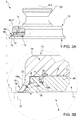
Figure 3b illustrates, on an enlarged scale, a detail ofFigure 3a ; -
Figure 4a illustrates in side view and on an enlarged scale, a capsule intended to contain an anhydrous material for the production of a beverage and obtained starting from a membrane and a cup-shaped body, in an unassembled condition; -
Figure 4b shows the capsule inFigure 4a in an assembled condition; and -
Figure 5 is an exploded side view, in partial cross-section and with parts removed for clarity, of a device for manufacturing membranes starting from a starting from a sheet of packaging material made according to an alternative embodiment of this invention. - With reference to the attached figures, the reference number 1 represents, as a whole, a device for
manufacturing membranes 2 for capsules 3 adapted to contain an anhydrous material for the production of a beverage, in particular anhydrous material in the form of powder, grains or leaves, such as coffee, tea, barley, cocoa, or the like, starting from asheet 4 of packaging material, in particular asheet 4 of malleable material, for example aluminium. - In particular, the capsules 3 are intended for use in extractor machines for producing a generally single-serve beverage, starting from a single capsule, according to a known method not described in detail.
- According to this preferred and non-limiting embodiment, the device 1 is a manually operated device intended to be used and manually operated by a user for the purpose of making (fabricating) a
membrane 2 starting from thesheet 4 of packaging material. The user subsequently uses themembrane 2 to assemble a capsule 3 from a hollow, cup-shaped body 5 open at the top and themembrane 2, which is configured to close the cup-shaped body 5 at the top, as can be seen inFigures 4a and 4b . - For example, the portable manual device described in
IT102018000007826 membrane 2 is applied to the cup-shaped body 5 in the manner described below, may be used to assemble themembrane 2 and the cup-shaped body 5. - Specifically, as can be seen in
Figures 4a and 4b , the cup-shaped body 5 has an axis of symmetry A and comprises a supportingbase 5a, arranged at a lower axial end of the cup-shaped body 5, and anannular flange 6, which extends radially outwards from an upper axial end of the cup-shaped body 5. - In greater detail, the
flange 6 extends integrally from the cup-shaped body 5 and has an upper axialannular surface 6a and a lower axialannular surface 6b. - The cup-
shaped body 5 has a substantially frustoconical flanged shape, with the upper end having a diameter greater than the diameter of the lower end. - Moreover, the cup-
shaped body 5 defines, coaxially inside it, a cavity 7 that is open at the top at the upper end of the cup-shaped body 5 and is intended to house, in use, the aforesaid anhydrous material. - Preferably, the cavity 7 has such dimensions that the cup-
shaped body 5 can be considered a thin-walled body. - The cavity 7 is intended to be closed at the top by the
membrane 2, which for this purpose is applied, in use, to the cup-shaped body 5 at the upper end thereof, i.e. at theflange 6. - More specifically, the
membrane 2 comprises an annularperipheral portion 2a having a diameter greater than the diameter of theflange 6. In particular, themembrane 2, in a first step of assembling the capsule 3, overlaps - is, in particular, supported by - theupper surface 6a of theflange 6. - When the membrane overlaps - is, in particular, supported by - the
upper surface 6a, theperipheral portion 2a protrudes radially from the outer rim of theflange 6. - The assembly of the capsule 3 is borne out as described in
IT102018000007826 peripheral portion 2a is bent in a "U" shape around theflange 6 using the portable manual assembly device described therein. - As can be seen in
Figure 1 , the device 1 comprises: - a
base body 8 having a longitudinal axis B, preferably straight, and including a supportingbase 10 and a raisedportion 11 extending coaxially from the supportingbase 10 to an endaxial surface 12 thereof; and - a
cutting body 13 including amain portion 14 having a longitudinal axis C, preferably straight, and aperipheral portion 15 extending coaxially from themain portion 14, in particular from a peripheral edge of themain portion 14. - Specifically, the
axial surface 12 defines an end axial free surface of the raisedportion 11, which is configured to receive thesheet 4 on theaxial surface 12. - Thus, the
axial surface 12 defines a support surface for thesheet 4 of packaging material. - According to this preferred and non-limiting embodiment, the device 1 has a substantially circular shape.
- More specifically, the
base body 8 and thecutting body 13 are configured as two distinct and separate bodies that can be releasably coupled to each other and have a substantially circular profile around their respective axes B and C, in order to makecircular membranes 2 for assembly with respective cup-shaped bodies 5 of the type illustrated inFigures 4a and 4b . - Alternatively, the device 1 may have a different shape, for example substantially square, square with rounded corners, rectangular, polygonal, or oval, etc.
- It should be noted that, in this description, the term "substantially" is intended to take into account the normal geometric tolerances necessarily present in and between the device 1 components.
- In view of what has been described above, the
support base 10 is substantially circular in shape about the axis B, themain portion 14 is substantially circular in shape about the axis C, and theperipheral portion 15 is defined by an annular protuberance extending, in particular extending integrally, from the annular end edge of themain portion 14. - The device 1 also comprises:
- a
cutting tooth 16 having a closed-line endless profile and borne by thecutting body 13 coaxially to the axis B, in particular extending axially, more particularly extending integrally, from themain portion 14 to a position radially more inward than theperipheral portion 15; and - a
groove 17 having a closed-line endless profile and coaxially borne by thebase body 8, in particular being defined by a recess extending axially in the raisedportion 11 coaxially to the axis B and open at theaxial surface 12. - In use, the
cutting body 13 can be releasably coupled to thebase body 8 so that theperipheral portion 15 accommodates, at least partially, the raisedportion 11 and so that thecutting tooth 16 engages thegroove 17 to determine a cut of thesheet 4 and the production of amembrane 2 for separating a piece of thesheet 4 by said cut. - In particular, the
peripheral portion 15 has an axial extension from themain portion 14 that is less than the axial extension of the raisedportion 11 from the supportingbase 10, so that the raisedportion 11 is partially, and not totally, accommodated within theperipheral portion 15 during said coupling. - In the described example, the cutting
tooth 16 is annular, in particular circular, about the axis C and thegroove 17 is annular, in particular circular, about the axis B. - Alternatively, the cutting
tooth 16 and thegroove 17 could have a profile defined by any closed-line endless profile around the respective axis C, B, for example a profile that is square with rounded corners, square, rectangular, polygonal, etc. In this case, the resultingmembrane 2 will have a perimeter tracing the profile of the cuttingtooth 16 and thegroove 17. - Clearly, for the purpose of the above-mentioned engagement, the cutting
tooth 16 and thegroove 17 have the same profile, so that one engages the other as a result of the coupling between the cuttingbody 13 and thebase body 8. - The cutting
tooth 16 and thegroove 17 are conveniently arranged at the same radial distance from the respective axes C and B, so that the cuttingtooth 16 engages thegroove 17 during the above-mentioned coupling. - Advantageously, the raised
portion 11 comprises afrustoconical portion 18 extending from the supportingbase 10 coaxially to the axis B and theperipheral portion 15 comprises afrustoconical portion 19 extending from the main portion coaxially to the axis C. The one frustoconicalportion 18 and the otherfrustoconical portion 19 are configured to slidably cooperate with each other during the coupling of the cuttingbody 13 with thebase body 8 to determine the centring of the axis B with the axis C. - Specifically, the
frustoconical portion 18 comprises an external frustoconicallateral surface 18a and thefrustoconical portion 19 comprises an inner frustoconicallateral surface 19a configured to slidably cooperate with thesurface 18a during the above-mentioned coupling, so as to determine the centring of the axis B with the axis C. - Thus, the one
surface 18a and theother surface 19a face each other when the cuttingtooth 16 engages thegroove 17. In particular, the onesurface 18a and theother surface 19a are parallel to each other when the cuttingtooth 16 engages thegroove 17. - Thanks to the above-described configuration, the user is able to perform the above-mentioned centring easily and without having to worry about precisely coupling the
base body 8 and the cuttingbody 13, and without the aid of axial guiding elements for the cuttingbody 13. This centring will cause, in use, the correct alignment between cuttingbody 13 andbase body 8 and, thus, between cuttingtooth 16 andgroove 18, thus determining a cut in thesheet 4 under rating conditions. - Suitably, the
frustoconical portion 18 is tapered toward theaxial surface 12 and thefrustoconical portion 19 is tapered toward themain portion 14. - In use, the device 1 is configured to be used with the
base body 8 arranged on a support surface (not shown) so that the axis B is perpendicular to the support surface (vertical, if the support surface is horizontal) and the axis C is perpendicular to the support surface (vertical, if the support surface is horizontal) after centring and coupling has been completed. Preferably, the support surface may be defined by a user's hand. - If the support plane is horizontal, it can be said that the one
frustoconical portion 18 and the otherfrustoconical portion 19 are tapered upwards. - The above-described configuration not only allows centring of the axis B with the axis C, but also causes a tensioning of the
sheet 4 radially outwards, prior to the cutting of thesheet 4 itself. - More specifically, during coupling of the cutting
body 13 to thebase body 8, the onefrustoconical portion 19 slides from top to bottom along the otherfrustoconical portion 18. This movement, in addition to determining the centring of the axes B and C, causes a substantially, axially symmetric tensioning of thesheet 4 in an outward radial direction. - Thus, the
sheet 4 is well stretched and the cuttingtooth 16 can easily penetrate it, compared to cases where thesheet 4 is not well stretched, and can therefore easily cut it cleanly and neatly. - The
frustoconical portion 18 is preferably tilted in relation to a direction orthogonal to the axis B by an angle α between 40° and 70°, preferably between 50° and 60°, even more preferably 55° (Figure 3b ). In addition, thefrustoconical portion 19 is inclined with respect to a direction orthogonal to the axis C by an angle β between 110° and 140°, preferably between 120° and 130°, even more preferably 125° (Figure 3b ). - The Applicant noticed that these width values of the angles α and β define the optimal inclination that results in the
frustoconical walls sheet 4. - The cutting
tooth 16 and thegroove 17 conveniently have the same axial extension. Thus, the cuttingtooth 16 fully engages thegroove 17 during coupling of the cuttingbody 13 with thebase body 8. The device 1 is thus compact and sliding cooperation between thefrustoconical portions - Since the
sheet 4 is well stretched due to the cooperation between thefrustoconical portions tooth 16 with a cutting edge or blade. - Accordingly, as shown in
Figure 3b , the cuttingtooth 16 comprises anaxial cutting wall 16a, which is substantially flat and perpendicular to the axis C. More specifically, the cuttingtooth 16 has, in axial cross-section, a substantially quadrangular, in particular rectangular, profile, wherein the cuttingwall 16a defines the axial end surface of the axial prominence defining the cuttingtooth 16. - Thus, the cutting
tooth 16 is defined by a substantially cylindrical, hollow axial protuberance and is, moreover, free of a sharp axial cutting surface, i.e., a cutting edge or blade. - Appropriately, the
groove 17 comprises anaxial abutment wall 17a that is substantially flat and perpendicular to the axis B. More precisely, thegroove 17 has, in axial cross-section, a substantially quadrangular, in particular rectangular, profile, wherein theabutment wall 17a defines the bottom axial surface of the axial recess defining thegroove 17. - The cutting
wall 16a is configured to abut against theabutment wall 17a when the cuttingtooth 16 engages thegroove 17, so as to determine the complete separation of themembrane 2 from thesheet 4. - The separation occurs, in particular, at the inner diameter of the cutting
tooth 16 and of thegroove 17. - According to this preferred and non-limiting embodiment, the raised
portion 11 further comprises acylindrical portion 20 coaxial to the axis B and extending axially from thefrustoconical portion 18 to theaxial surface 12; and theperipheral portion 15 also comprises acylindrical portion 21 coaxial to the axis C and axially interposed between themain portion 14 and thefrustoconical portion 19. - Specifically, the raised
portion 11 consists of thefrustoconical portion 18 and thecylindrical portion 20 that overlies thefrustoconical portion 18 and has theaxial surface 12; and theperipheral portion 15 consists of thecylindrical portion 21 extending, in particular extending integrally, axially from themain portion 14 and thefrustoconical portion 19, which in turn extends, in particular extends integrally, from thecylindrical portion 21. - In use, the one
cylindrical portion 20 and the othercylindrical portion 21 radially face each other, in particular they are parallel to each other when the cuttingtooth 16 engages thegroove 17. - The
cylindrical portion 20 conveniently has an axial extension corresponding to the axial extension of thegroove 17 and thecylindrical portion 21 has an axial extension corresponding to the axial extension of the cuttingtooth 16. - This configuration ensures that the centring of the axes B and C and the tensioning of the
sheet 4 take place before the cuttingtooth 16 completes its stroke inside thegroove 17, and, in any case, prior to the cutting of the packaging material. - A nominal cut of the
sheet 4 is, thus, ensured. - The cutting
body 13 is preferably provided with ahandle 22, in particular coaxial to the axis C and extending from the opposite side of themain portion 14 to theperipheral portion 15, which facilitates the user's manipulation thereof. - The operation of the device 1 according to this invention will be described below, with particular reference to an initial condition wherein the
base body 8 is arranged on a support plane and thesheet 4 is supported on theaxial surface 12. - In this condition, the user grasps the cutting
body 13, initially separated from thebase body 8, and overlaps it with thebase body 8 itself, moving it towards the latter. As this movement continues, thefrustoconical portions sheet 4. - At this point, the cutting
tooth 16 engages thegroove 17, thereby determining the cutting of thesheet 4 and the creation of themembrane 2. - With reference to
Figure 5 , the reference number 1' represents a device formanufacturing membranes 2 according to an alternative embodiment of this invention. - Since the alternative device 1' is functionally and structurally similar to the device 1, only the distinctive features with respect to the latter will be described, using, where possible, the same references for the corresponding parts and components.
- In particular, the alternative device 1' differs from the device 1 in that the
base body 8 comprises an additional groove 17' of the type described above and defining an additional recess in the raisedportion 11 and arranged in a position radially distant from thegroove 17. - In addition, the device 1' comprises a series of, in particular at least two, interchangeable elements 30' that can be alternatively, releasably coupled to the
main portion 14 of the cuttingbody 13, coaxially to the axis C. - Specifically, each interchangeable element 30' is defined by a circular plate body bearing a
respective cutting tooth 16, 16' of the type described above extending axially from the respective plate body. - More specifically, the cutting
tooth 16 is arranged at a radial distance from the axis C different from the radial distance at which the cutting tooth 16' of the other interchangeable element 30' is arranged. These distances are measured when the interchangeable elements 30' are coaxially coupled to the cuttingbody 13; therefore, they refer to the axis C. - The cutting
tooth 16 will be conveniently arranged at a radial distance such that it engages the correspondinggroove 17 and the cutting tooth 16' will be arranged at a radial distance such that it engages the groove 17'. - Thus, the radial distance from the axis C of the cutting
teeth 16, 16' corresponds to the radial distance from the axis B of thegrooves 17, 17', respectively. - In the light of what has been described above, it is possible to obtain
membranes 2 of a different format, i.e. of a different diameter and, therefore, adapted for a different capsule format 3, by simply replacing the interchangeable element 30'. - The interchangeable elements 30' are preferably coupled to the cutting
body 13 using clamping means, for example a screw 31'. - The advantages enabled by the device 1, 1' manufactured according to this invention will be apparent from an examination of the features thereof.
- In particular, thanks to the presence of the
frustoconical portions base body 8 and the cuttingbody 13. Such centring will determine, in use, the correct alignment between cuttingbody 13 andbase body 8 and, thus, between cuttingtooth 16 andgroove 18, thus resulting in a cut of thesheet 4 under rating conditions. - The
frustoconical portions body 13 superfluous, further simplifying the architecture of the device 1 and favouring its portability. - The interaction of the
frustoconical portions sheet 4 radially outwardly, prior to the cutting of thesheet 4 itself. Thesheet 4 is, thus, tightly stretched and the cuttingtooth 16 can penetrate it, and thus cut it, cleanly despite not having a cutting edge or blade. The device 1 is, thus, less dangerous and, therefore, more portable (and/or pocket-sized). - Finally, in the case of the device 1', thanks to the presence of the interchangeable elements 30', each bearing a
respective cutting tooth 16, 16' of different dimensions, it is possible to obtainmembranes 2 of a different format, i.e., of a different diameter and, therefore, adapted for a different capsule format 3, by simply replacing the interchangeable element 30'. - It is clear that the device 1, 1' described and illustrated herein can be subject to modifications and variations without however departing from the scope of protection defined by the claims.
- In particular, the cutting
tooth 16 could be borne by thebase body 8 and thegroove 17 could be borne, i.e. made, in the cuttingbody 13, with appropriate structural modifications. - For example, in this case, the
cylindrical portion 20 would have the same axial extension as the cuttingtooth 16 and thecylindrical portion 21 would have the same axial extension as thegroove 17.
Claims (10)
- A device (1, 1') for manufacturing membranes (2) for capsules (3) adapted to contain an anhydrous material for the production of a beverage starting from a sheet (4) of packaging material, said device (1, 1') comprising:- a base body (8) having a first longitudinal axis (B) and including a supporting base (10) and a raised portion (11) extending coaxially from the supporting base (10) up to an axial end surface (12) thereof and configured to receive on said axial surface (12) said sheet (4) of packaging material;- a cutting body (13) including a main portion (14) having a second longitudinal axis (C) and a peripheral portion (15) extending coaxially from the main portion (14) ;- a cutting tooth (16, 16') having a closed-line endless profile and carried coaxially by one of said raised portion (11) and main portion (14); and- a groove (17, 17') having a closed-line endless profile and carried coaxially by the other of said raised portion (11) and main portion (14);said cutting body (13) being releasably couplable to said base body (8) so that the peripheral portion (15) at least partially accomodates the raised portion (11) and so that the cutting tooth (16, 16') engages the groove (17, 17') to determine a cut of the packaging material and the production of one said membrane (2) from said sheet (4);
said raised portion (11) comprising a first frustoconical portion (18) extending from the supporting base (10) coaxially to the first axis (10);
said peripheral portion (15) comprising a second frustoconical portion (19) extending from the main portion (14) coaxially to the second axis (C);
said first (18) and second (19) frustoconical portions being configured to slidably cooperate with one another during said coupling to determine a centring of said first axis (B) with said second axis (C). - The device as claimed in claim 1, wherein said first frustoconical portion (18) comprises a first frustoconical lateral surface (18a) and wherein the second frustoconical portion (19) comprises a second frustoconical lateral surface (19a) configured to slidably cooperate with said first frustoconical lateral surface (18a) during said coupling;
said first frustoconical lateral surface (18a) and said second frustoconical lateral surface (19a) facing one other when said cutting tooth (16) engages said groove (17). - The device as claimed in claim 1 or 2, wherein said first frustoconical portion (18) is axially tapered towards said axial surface (12) and wherein said second frustoconical portion (19) is axially tapered towards said main portion (14).
- The device as claimed in claim 3, wherein said first frustoconical portion (18) is tilted with respect to a direction orthogonal to the first axis (B) by an angle (α) between 40° and 70°, preferably between 50° and 60°, even more preferably 55°;
and wherein said second frustoconical portion (19) is tilted with respect to a direction orthogonal to the second axis (C) by an angle (β) between 110° and 140°, preferably between 120° and 130°, even more preferably 125°. - The device as claimed in any one of the preceding claims, wherein said peripheral portion (15) has a smaller axial extension, calculated from said main portion (14), than the axial extension of the raised portion (11), calculated from said supporting base (10), so that said raised portion (11) is housed partially inside said peripheral portion (15) once said coupling has been performed.
- The device as claimed in any one of the preceding claims, wherein said cutting tooth (16) is annular coaxially to the axis (C) of said one of said raised portion (11) and main portion (14) and comprises an axial cutting wall (16a), substantially flat and perpendicular to the axis (C) of said one of said raised portion (11) and main portion (14);
said groove (17) being annular coaxially to the axis (B) of said other of said raised portion (11) and main portion (14) and comprising an axial abutment wall (17a), substantially flat and perpendicular to the axis (B) of said other of said raised portion (11) and main portion (14);
said cutting wall (16a) being configured to abut against said abutment wall (17a) when said cutting tooth (16) engages said groove (17). - The device as claimed in any one of the preceding claims, wherein said cutting tooth (16) is carried by said cutting body (13) and extends axially from said main portion (14) at a position radially innermost with respect to said peripheral portion (15);
and wherein said groove (17) is obtained in said base body (8) and defines a recess of said raised portion (11) open at said axial surface (12). - The device as claimed in any one of the preceding claims, wherein said raised portion (11) further comprises a first cylindrical portion (20) coaxial to the first axis (B), extending axially from said first frustoconical portion (18) up to said axial surface (12);
and wherein said peripheral portion (15) further comprises a second cylindrical portion (21) coaxial to the second axis (C) and axially interposed between said main portion (14) and said second frustoconical portion (19) ;
said first cylindrical portion (20) and said second cylindrical portion (21) radially facing one another when said cutting tooth (16) engages said groove (17). - The device as claimed in claim 7 and 8, wherein said first cylindrical portion (20) has an axial extension, with respect to said first axis (B), corresponding to the axial extension of said groove (17) ;
and wherein said second cylindrical portion (21) has an axial extension, with respect to said second axis (C), corresponding to the axial extension of said cutting tooth (16). - The device (1') as claimed in any one of claims 7 to 9, wherein said base body (8) comprises at least a further groove (17') defining a further recess in said raised portion (11) and arranged in a position radially spaced from said groove (17), with respect to said first axis (B);
said device (1') further comprising at least two interchangeable elements (30'), alternatively couplable in a releasable manner to the main portion (14) of the cutting body (13), coaxially to the second axis (C), and carrying a respective cutting tooth (16, 16') extending axially from the relative interchangeable element (30'); said cutting teeth (16, 16') being arranged at different respective radial distances from the second axis (C), measured when the interchangeable elements (30') are coupled, alternatively, to the cutting body (13), each radial distance substantially corresponding to the radial distance from the first axis (B) of the groove (17, 17') adapted to be engaged by the relative cutting tooth (16, 16').
Applications Claiming Priority (1)
| Application Number | Priority Date | Filing Date | Title |
|---|---|---|---|
| IT102020000001174A IT202000001174A1 (en) | 2020-01-22 | 2020-01-22 | DEVICE FOR MANUFACTURING MEMBRANES FOR CAPSULES SUITABLE TO CONTAIN ANHYDROUS MATERIAL FOR THE PRODUCTION OF A BEVERAGE STARTING FROM A SHEET OF PACKAGING MATERIAL |
Publications (2)
| Publication Number | Publication Date |
|---|---|
| EP3854551A1 true EP3854551A1 (en) | 2021-07-28 |
| EP3854551B1 EP3854551B1 (en) | 2022-08-17 |
Family
ID=70295858
Family Applications (1)
| Application Number | Title | Priority Date | Filing Date |
|---|---|---|---|
| EP21153089.4A Active EP3854551B1 (en) | 2020-01-22 | 2021-01-22 | A device for manufacturing from a sheet of packaging material membranes for capsules of a beverage, such capsules adapted to contain an anhydrous material |
Country Status (2)
| Country | Link |
|---|---|
| EP (1) | EP3854551B1 (en) |
| IT (1) | IT202000001174A1 (en) |
Citations (5)
| Publication number | Priority date | Publication date | Assignee | Title |
|---|---|---|---|---|
| DE958157C (en) * | 1954-07-07 | 1957-02-14 | Emil Duerr | Stamping tool for making rings from elastic materials such as rubber, cork or the like. |
| DE3603627A1 (en) * | 1985-10-23 | 1987-04-23 | Kln Ultraschall Gmbh | Process and apparatus for making openings in containers of thermoplastic materials |
| EP0780310A1 (en) * | 1995-12-19 | 1997-06-25 | OPEM S.r.l. | Cutting device in apparatus for making coffee wafers for automatic espresso-coffee machines |
| US6357972B1 (en) * | 2000-02-29 | 2002-03-19 | Daimlerchrysler Corporation | Tool and method for cutting holes in film |
| IT201800007826A1 (en) | 2018-08-03 | 2020-02-03 | Roberto Mei | METHOD AND DEVICE FOR ASSEMBLING A CAPSULE CONTAINING ANHYDROUS MATERIAL FOR THE PRODUCTION OF A BEVERAGE |
-
2020
- 2020-01-22 IT IT102020000001174A patent/IT202000001174A1/en unknown
-
2021
- 2021-01-22 EP EP21153089.4A patent/EP3854551B1/en active Active
Patent Citations (5)
| Publication number | Priority date | Publication date | Assignee | Title |
|---|---|---|---|---|
| DE958157C (en) * | 1954-07-07 | 1957-02-14 | Emil Duerr | Stamping tool for making rings from elastic materials such as rubber, cork or the like. |
| DE3603627A1 (en) * | 1985-10-23 | 1987-04-23 | Kln Ultraschall Gmbh | Process and apparatus for making openings in containers of thermoplastic materials |
| EP0780310A1 (en) * | 1995-12-19 | 1997-06-25 | OPEM S.r.l. | Cutting device in apparatus for making coffee wafers for automatic espresso-coffee machines |
| US6357972B1 (en) * | 2000-02-29 | 2002-03-19 | Daimlerchrysler Corporation | Tool and method for cutting holes in film |
| IT201800007826A1 (en) | 2018-08-03 | 2020-02-03 | Roberto Mei | METHOD AND DEVICE FOR ASSEMBLING A CAPSULE CONTAINING ANHYDROUS MATERIAL FOR THE PRODUCTION OF A BEVERAGE |
Also Published As
| Publication number | Publication date |
|---|---|
| IT202000001174A1 (en) | 2021-07-22 |
| EP3854551B1 (en) | 2022-08-17 |
Similar Documents
| Publication | Publication Date | Title |
|---|---|---|
| JP6051052B2 (en) | Press part molding method, press part manufacturing method, and press part molding die | |
| US20140374472A1 (en) | Apparatus and methodfor moulding containers of paper material | |
| JP6051053B2 (en) | Press part molding method, press part manufacturing method, and press part molding die | |
| EP0743871A1 (en) | Method for the manufacture of filter wells | |
| EP3854551B1 (en) | A device for manufacturing from a sheet of packaging material membranes for capsules of a beverage, such capsules adapted to contain an anhydrous material | |
| CN105328071B (en) | For manufacturing the device and method for being suitable for the coupling body for being equipped with tooth or teeth portion section of synchronization system | |
| KR101975202B1 (en) | apparatus for manufacturing split stopper for steel rod coupler | |
| KR900010987Y1 (en) | Stapler | |
| EP3851388B1 (en) | Device and method for assembling a capsule containing an anhydrous material for the production of a beverage | |
| US11766802B2 (en) | Die cutter holding and lifting apparatus | |
| US9227218B1 (en) | Double-sealant tube structure for caulking gun | |
| JP2875496B2 (en) | Equipment for manufacturing paper tray containers | |
| KR102093681B1 (en) | Method and apparatus for continuous manufacture of aeration pipe clips | |
| CN211161311U (en) | Rolling stamping device | |
| JP6344780B2 (en) | Manufacture of can lids | |
| US20150151904A1 (en) | Disposable capsule for the production of an aromatic beverage, method and process machine for making it | |
| RU2017119659A (en) | METHOD FOR MAKING A SCAN | |
| EP3088791A1 (en) | Perforable cartridge for liquefied gas provided with a safety device | |
| IT201800007826A1 (en) | METHOD AND DEVICE FOR ASSEMBLING A CAPSULE CONTAINING ANHYDROUS MATERIAL FOR THE PRODUCTION OF A BEVERAGE | |
| US20060183617A1 (en) | Forming catch tabs on paperboard food container components for retaining containers and lids in releasable attachment | |
| US4024748A (en) | Apparatus for producing annular metallic blanks for metallic rings | |
| KR101747380B1 (en) | Big basket manufacturing method | |
| JPH08168839A (en) | Manufacturing method of caulking ring | |
| TWM481079U (en) | Molding die of thin aluminium utensil | |
| WO1995016876A1 (en) | A candle container, a method of manufacturing a candle container, a method of attaching a wick to a candle container and a method of manufacturing a candle comprising a container filled with fuel |
Legal Events
| Date | Code | Title | Description |
|---|---|---|---|
| PUAI | Public reference made under article 153(3) epc to a published international application that has entered the european phase |
Free format text: ORIGINAL CODE: 0009012 |
|
| STAA | Information on the status of an ep patent application or granted ep patent |
Free format text: STATUS: THE APPLICATION HAS BEEN PUBLISHED |
|
| AK | Designated contracting states |
Kind code of ref document: A1 Designated state(s): AL AT BE BG CH CY CZ DE DK EE ES FI FR GB GR HR HU IE IS IT LI LT LU LV MC MK MT NL NO PL PT RO RS SE SI SK SM TR |
|
| STAA | Information on the status of an ep patent application or granted ep patent |
Free format text: STATUS: REQUEST FOR EXAMINATION WAS MADE |
|
| 17P | Request for examination filed |
Effective date: 20211014 |
|
| RBV | Designated contracting states (corrected) |
Designated state(s): AL AT BE BG CH CY CZ DE DK EE ES FI FR GB GR HR HU IE IS IT LI LT LU LV MC MK MT NL NO PL PT RO RS SE SI SK SM TR |
|
| GRAP | Despatch of communication of intention to grant a patent |
Free format text: ORIGINAL CODE: EPIDOSNIGR1 |
|
| STAA | Information on the status of an ep patent application or granted ep patent |
Free format text: STATUS: GRANT OF PATENT IS INTENDED |
|
| RIC1 | Information provided on ipc code assigned before grant |
Ipc: B26F 1/44 20060101ALI20220217BHEP Ipc: B26F 1/38 20060101AFI20220217BHEP |
|
| INTG | Intention to grant announced |
Effective date: 20220309 |
|
| GRAS | Grant fee paid |
Free format text: ORIGINAL CODE: EPIDOSNIGR3 |
|
| GRAA | (expected) grant |
Free format text: ORIGINAL CODE: 0009210 |
|
| STAA | Information on the status of an ep patent application or granted ep patent |
Free format text: STATUS: THE PATENT HAS BEEN GRANTED |
|
| AK | Designated contracting states |
Kind code of ref document: B1 Designated state(s): AL AT BE BG CH CY CZ DE DK EE ES FI FR GB GR HR HU IE IS IT LI LT LU LV MC MK MT NL NO PL PT RO RS SE SI SK SM TR |
|
| REG | Reference to a national code |
Ref country code: CH Ref legal event code: EP |
|
| REG | Reference to a national code |
Ref country code: DE Ref legal event code: R096 Ref document number: 602021000310 Country of ref document: DE |
|
| REG | Reference to a national code |
Ref country code: IE Ref legal event code: FG4D |
|
| REG | Reference to a national code |
Ref country code: AT Ref legal event code: REF Ref document number: 1511884 Country of ref document: AT Kind code of ref document: T Effective date: 20220915 |
|
| REG | Reference to a national code |
Ref country code: NL Ref legal event code: MP Effective date: 20220817 |
|
| REG | Reference to a national code |
Ref country code: LT Ref legal event code: MG9D |
|
| PG25 | Lapsed in a contracting state [announced via postgrant information from national office to epo] |
Ref country code: SE Free format text: LAPSE BECAUSE OF FAILURE TO SUBMIT A TRANSLATION OF THE DESCRIPTION OR TO PAY THE FEE WITHIN THE PRESCRIBED TIME-LIMIT Effective date: 20220817 Ref country code: RS Free format text: LAPSE BECAUSE OF FAILURE TO SUBMIT A TRANSLATION OF THE DESCRIPTION OR TO PAY THE FEE WITHIN THE PRESCRIBED TIME-LIMIT Effective date: 20220817 Ref country code: PT Free format text: LAPSE BECAUSE OF FAILURE TO SUBMIT A TRANSLATION OF THE DESCRIPTION OR TO PAY THE FEE WITHIN THE PRESCRIBED TIME-LIMIT Effective date: 20221219 Ref country code: NO Free format text: LAPSE BECAUSE OF FAILURE TO SUBMIT A TRANSLATION OF THE DESCRIPTION OR TO PAY THE FEE WITHIN THE PRESCRIBED TIME-LIMIT Effective date: 20221117 Ref country code: NL Free format text: LAPSE BECAUSE OF FAILURE TO SUBMIT A TRANSLATION OF THE DESCRIPTION OR TO PAY THE FEE WITHIN THE PRESCRIBED TIME-LIMIT Effective date: 20220817 Ref country code: LV Free format text: LAPSE BECAUSE OF FAILURE TO SUBMIT A TRANSLATION OF THE DESCRIPTION OR TO PAY THE FEE WITHIN THE PRESCRIBED TIME-LIMIT Effective date: 20220817 Ref country code: LT Free format text: LAPSE BECAUSE OF FAILURE TO SUBMIT A TRANSLATION OF THE DESCRIPTION OR TO PAY THE FEE WITHIN THE PRESCRIBED TIME-LIMIT Effective date: 20220817 Ref country code: FI Free format text: LAPSE BECAUSE OF FAILURE TO SUBMIT A TRANSLATION OF THE DESCRIPTION OR TO PAY THE FEE WITHIN THE PRESCRIBED TIME-LIMIT Effective date: 20220817 |
|
| REG | Reference to a national code |
Ref country code: AT Ref legal event code: MK05 Ref document number: 1511884 Country of ref document: AT Kind code of ref document: T Effective date: 20220817 |
|
| PG25 | Lapsed in a contracting state [announced via postgrant information from national office to epo] |
Ref country code: PL Free format text: LAPSE BECAUSE OF FAILURE TO SUBMIT A TRANSLATION OF THE DESCRIPTION OR TO PAY THE FEE WITHIN THE PRESCRIBED TIME-LIMIT Effective date: 20220817 Ref country code: IS Free format text: LAPSE BECAUSE OF FAILURE TO SUBMIT A TRANSLATION OF THE DESCRIPTION OR TO PAY THE FEE WITHIN THE PRESCRIBED TIME-LIMIT Effective date: 20221217 Ref country code: HR Free format text: LAPSE BECAUSE OF FAILURE TO SUBMIT A TRANSLATION OF THE DESCRIPTION OR TO PAY THE FEE WITHIN THE PRESCRIBED TIME-LIMIT Effective date: 20220817 Ref country code: GR Free format text: LAPSE BECAUSE OF FAILURE TO SUBMIT A TRANSLATION OF THE DESCRIPTION OR TO PAY THE FEE WITHIN THE PRESCRIBED TIME-LIMIT Effective date: 20221118 |
|
| PG25 | Lapsed in a contracting state [announced via postgrant information from national office to epo] |
Ref country code: SM Free format text: LAPSE BECAUSE OF FAILURE TO SUBMIT A TRANSLATION OF THE DESCRIPTION OR TO PAY THE FEE WITHIN THE PRESCRIBED TIME-LIMIT Effective date: 20220817 Ref country code: RO Free format text: LAPSE BECAUSE OF FAILURE TO SUBMIT A TRANSLATION OF THE DESCRIPTION OR TO PAY THE FEE WITHIN THE PRESCRIBED TIME-LIMIT Effective date: 20220817 Ref country code: ES Free format text: LAPSE BECAUSE OF FAILURE TO SUBMIT A TRANSLATION OF THE DESCRIPTION OR TO PAY THE FEE WITHIN THE PRESCRIBED TIME-LIMIT Effective date: 20220817 Ref country code: DK Free format text: LAPSE BECAUSE OF FAILURE TO SUBMIT A TRANSLATION OF THE DESCRIPTION OR TO PAY THE FEE WITHIN THE PRESCRIBED TIME-LIMIT Effective date: 20220817 Ref country code: CZ Free format text: LAPSE BECAUSE OF FAILURE TO SUBMIT A TRANSLATION OF THE DESCRIPTION OR TO PAY THE FEE WITHIN THE PRESCRIBED TIME-LIMIT Effective date: 20220817 Ref country code: AT Free format text: LAPSE BECAUSE OF FAILURE TO SUBMIT A TRANSLATION OF THE DESCRIPTION OR TO PAY THE FEE WITHIN THE PRESCRIBED TIME-LIMIT Effective date: 20220817 |
|
| REG | Reference to a national code |
Ref country code: DE Ref legal event code: R097 Ref document number: 602021000310 Country of ref document: DE |
|
| PG25 | Lapsed in a contracting state [announced via postgrant information from national office to epo] |
Ref country code: SK Free format text: LAPSE BECAUSE OF FAILURE TO SUBMIT A TRANSLATION OF THE DESCRIPTION OR TO PAY THE FEE WITHIN THE PRESCRIBED TIME-LIMIT Effective date: 20220817 Ref country code: EE Free format text: LAPSE BECAUSE OF FAILURE TO SUBMIT A TRANSLATION OF THE DESCRIPTION OR TO PAY THE FEE WITHIN THE PRESCRIBED TIME-LIMIT Effective date: 20220817 |
|
| P01 | Opt-out of the competence of the unified patent court (upc) registered |
Effective date: 20230508 |
|
| PLBE | No opposition filed within time limit |
Free format text: ORIGINAL CODE: 0009261 |
|
| STAA | Information on the status of an ep patent application or granted ep patent |
Free format text: STATUS: NO OPPOSITION FILED WITHIN TIME LIMIT |
|
| PG25 | Lapsed in a contracting state [announced via postgrant information from national office to epo] |
Ref country code: AL Free format text: LAPSE BECAUSE OF FAILURE TO SUBMIT A TRANSLATION OF THE DESCRIPTION OR TO PAY THE FEE WITHIN THE PRESCRIBED TIME-LIMIT Effective date: 20220817 |
|
| 26N | No opposition filed |
Effective date: 20230519 |
|
| PG25 | Lapsed in a contracting state [announced via postgrant information from national office to epo] |
Ref country code: SI Free format text: LAPSE BECAUSE OF FAILURE TO SUBMIT A TRANSLATION OF THE DESCRIPTION OR TO PAY THE FEE WITHIN THE PRESCRIBED TIME-LIMIT Effective date: 20220817 |
|
| PG25 | Lapsed in a contracting state [announced via postgrant information from national office to epo] |
Ref country code: LU Free format text: LAPSE BECAUSE OF NON-PAYMENT OF DUE FEES Effective date: 20230122 |
|
| REG | Reference to a national code |
Ref country code: BE Ref legal event code: MM Effective date: 20230131 |
|
| PG25 | Lapsed in a contracting state [announced via postgrant information from national office to epo] |
Ref country code: BE Free format text: LAPSE BECAUSE OF NON-PAYMENT OF DUE FEES Effective date: 20230131 |
|
| PG25 | Lapsed in a contracting state [announced via postgrant information from national office to epo] |
Ref country code: IE Free format text: LAPSE BECAUSE OF NON-PAYMENT OF DUE FEES Effective date: 20230122 |
|
| PG25 | Lapsed in a contracting state [announced via postgrant information from national office to epo] |
Ref country code: IT Free format text: LAPSE BECAUSE OF FAILURE TO SUBMIT A TRANSLATION OF THE DESCRIPTION OR TO PAY THE FEE WITHIN THE PRESCRIBED TIME-LIMIT Effective date: 20220817 |
|
| REG | Reference to a national code |
Ref country code: CH Ref legal event code: PL |
|
| PG25 | Lapsed in a contracting state [announced via postgrant information from national office to epo] |
Ref country code: CH Free format text: LAPSE BECAUSE OF NON-PAYMENT OF DUE FEES Effective date: 20240131 |
|
| PG25 | Lapsed in a contracting state [announced via postgrant information from national office to epo] |
Ref country code: CH Free format text: LAPSE BECAUSE OF NON-PAYMENT OF DUE FEES Effective date: 20240131 |
|
| PG25 | Lapsed in a contracting state [announced via postgrant information from national office to epo] |
Ref country code: BG Free format text: LAPSE BECAUSE OF FAILURE TO SUBMIT A TRANSLATION OF THE DESCRIPTION OR TO PAY THE FEE WITHIN THE PRESCRIBED TIME-LIMIT Effective date: 20220817 |
|
| PG25 | Lapsed in a contracting state [announced via postgrant information from national office to epo] |
Ref country code: BG Free format text: LAPSE BECAUSE OF FAILURE TO SUBMIT A TRANSLATION OF THE DESCRIPTION OR TO PAY THE FEE WITHIN THE PRESCRIBED TIME-LIMIT Effective date: 20220817 |
|
| PGFP | Annual fee paid to national office [announced via postgrant information from national office to epo] |
Ref country code: MC Payment date: 20250124 Year of fee payment: 5 |
|
| PGFP | Annual fee paid to national office [announced via postgrant information from national office to epo] |
Ref country code: DE Payment date: 20250129 Year of fee payment: 5 |
|
| PGFP | Annual fee paid to national office [announced via postgrant information from national office to epo] |
Ref country code: GB Payment date: 20250121 Year of fee payment: 5 |
|
| PG25 | Lapsed in a contracting state [announced via postgrant information from national office to epo] |
Ref country code: CY Free format text: LAPSE BECAUSE OF FAILURE TO SUBMIT A TRANSLATION OF THE DESCRIPTION OR TO PAY THE FEE WITHIN THE PRESCRIBED TIME-LIMIT; INVALID AB INITIO Effective date: 20210122 |
|
| PG25 | Lapsed in a contracting state [announced via postgrant information from national office to epo] |
Ref country code: HU Free format text: LAPSE BECAUSE OF FAILURE TO SUBMIT A TRANSLATION OF THE DESCRIPTION OR TO PAY THE FEE WITHIN THE PRESCRIBED TIME-LIMIT; INVALID AB INITIO Effective date: 20210122 |
|
| PG25 | Lapsed in a contracting state [announced via postgrant information from national office to epo] |
Ref country code: TR Free format text: LAPSE BECAUSE OF FAILURE TO SUBMIT A TRANSLATION OF THE DESCRIPTION OR TO PAY THE FEE WITHIN THE PRESCRIBED TIME-LIMIT Effective date: 20220817 |
|
| PGFP | Annual fee paid to national office [announced via postgrant information from national office to epo] |
Ref country code: FR Payment date: 20260126 Year of fee payment: 6 |
|
| PG25 | Lapsed in a contracting state [announced via postgrant information from national office to epo] |
Ref country code: CH Free format text: THE PATENT HAS BEEN ANNULLED BY A DECISION OF A NATIONAL AUTHORITY Effective date: 20240131 |
|
| PG25 | Lapsed in a contracting state [announced via postgrant information from national office to epo] |
Ref country code: MT Free format text: LAPSE BECAUSE OF NON-PAYMENT OF DUE FEES Effective date: 20230122 |