EP3854333A1 - Femoral implant - Google Patents
Femoral implant Download PDFInfo
- Publication number
- EP3854333A1 EP3854333A1 EP21153004.3A EP21153004A EP3854333A1 EP 3854333 A1 EP3854333 A1 EP 3854333A1 EP 21153004 A EP21153004 A EP 21153004A EP 3854333 A1 EP3854333 A1 EP 3854333A1
- Authority
- EP
- European Patent Office
- Prior art keywords
- resorbable
- femoral implant
- implant
- femoral
- porous
- Prior art date
- Legal status (The legal status is an assumption and is not a legal conclusion. Google has not performed a legal analysis and makes no representation as to the accuracy of the status listed.)
- Withdrawn
Links
- OENYTIWVRXNKIF-UHFFFAOYSA-N CC(C)(C)C[IH]CC[F]C Chemical compound CC(C)(C)C[IH]CC[F]C OENYTIWVRXNKIF-UHFFFAOYSA-N 0.000 description 1
Images


Classifications
-
- A—HUMAN NECESSITIES
- A61—MEDICAL OR VETERINARY SCIENCE; HYGIENE
- A61F—FILTERS IMPLANTABLE INTO BLOOD VESSELS; PROSTHESES; DEVICES PROVIDING PATENCY TO, OR PREVENTING COLLAPSING OF, TUBULAR STRUCTURES OF THE BODY, e.g. STENTS; ORTHOPAEDIC, NURSING OR CONTRACEPTIVE DEVICES; FOMENTATION; TREATMENT OR PROTECTION OF EYES OR EARS; BANDAGES, DRESSINGS OR ABSORBENT PADS; FIRST-AID KITS
- A61F2/00—Filters implantable into blood vessels; Prostheses, i.e. artificial substitutes or replacements for parts of the body; Appliances for connecting them with the body; Devices providing patency to, or preventing collapsing of, tubular structures of the body, e.g. stents
- A61F2/02—Prostheses implantable into the body
- A61F2/30—Joints
- A61F2/46—Special tools for implanting artificial joints
- A61F2/4603—Special tools for implanting artificial joints for insertion or extraction of endoprosthetic joints or of accessories thereof
- A61F2/4607—Special tools for implanting artificial joints for insertion or extraction of endoprosthetic joints or of accessories thereof of hip femoral endoprostheses
-
- A—HUMAN NECESSITIES
- A61—MEDICAL OR VETERINARY SCIENCE; HYGIENE
- A61B—DIAGNOSIS; SURGERY; IDENTIFICATION
- A61B17/00—Surgical instruments, devices or methods
- A61B17/56—Surgical instruments or methods for treatment of bones or joints; Devices specially adapted therefor
- A61B17/58—Surgical instruments or methods for treatment of bones or joints; Devices specially adapted therefor for osteosynthesis, e.g. bone plates, screws or setting implements
- A61B17/68—Internal fixation devices, including fasteners and spinal fixators, even if a part thereof projects from the skin
- A61B17/74—Devices for the head or neck or trochanter of the femur
- A61B17/742—Devices for the head or neck or trochanter of the femur having one or more longitudinal elements oriented along or parallel to the axis of the neck
-
- A—HUMAN NECESSITIES
- A61—MEDICAL OR VETERINARY SCIENCE; HYGIENE
- A61F—FILTERS IMPLANTABLE INTO BLOOD VESSELS; PROSTHESES; DEVICES PROVIDING PATENCY TO, OR PREVENTING COLLAPSING OF, TUBULAR STRUCTURES OF THE BODY, e.g. STENTS; ORTHOPAEDIC, NURSING OR CONTRACEPTIVE DEVICES; FOMENTATION; TREATMENT OR PROTECTION OF EYES OR EARS; BANDAGES, DRESSINGS OR ABSORBENT PADS; FIRST-AID KITS
- A61F2/00—Filters implantable into blood vessels; Prostheses, i.e. artificial substitutes or replacements for parts of the body; Appliances for connecting them with the body; Devices providing patency to, or preventing collapsing of, tubular structures of the body, e.g. stents
- A61F2/02—Prostheses implantable into the body
- A61F2/30—Joints
- A61F2/30767—Special external or bone-contacting surface, e.g. coating for improving bone ingrowth
- A61F2/30771—Special external or bone-contacting surface, e.g. coating for improving bone ingrowth applied in original prostheses, e.g. holes or grooves
-
- A—HUMAN NECESSITIES
- A61—MEDICAL OR VETERINARY SCIENCE; HYGIENE
- A61F—FILTERS IMPLANTABLE INTO BLOOD VESSELS; PROSTHESES; DEVICES PROVIDING PATENCY TO, OR PREVENTING COLLAPSING OF, TUBULAR STRUCTURES OF THE BODY, e.g. STENTS; ORTHOPAEDIC, NURSING OR CONTRACEPTIVE DEVICES; FOMENTATION; TREATMENT OR PROTECTION OF EYES OR EARS; BANDAGES, DRESSINGS OR ABSORBENT PADS; FIRST-AID KITS
- A61F2/00—Filters implantable into blood vessels; Prostheses, i.e. artificial substitutes or replacements for parts of the body; Appliances for connecting them with the body; Devices providing patency to, or preventing collapsing of, tubular structures of the body, e.g. stents
- A61F2/02—Prostheses implantable into the body
- A61F2/30—Joints
- A61F2/32—Joints for the hip
- A61F2/36—Femoral heads ; Femoral endoprostheses
- A61F2/3601—Femoral heads ; Femoral endoprostheses for replacing only the epiphyseal or metaphyseal parts of the femur, e.g. endoprosthetic femoral heads or necks directly fixed to the natural femur by internal fixation devices
- A61F2/3603—Femoral heads ; Femoral endoprostheses for replacing only the epiphyseal or metaphyseal parts of the femur, e.g. endoprosthetic femoral heads or necks directly fixed to the natural femur by internal fixation devices implanted without ablation of the whole natural femoral head
-
- A—HUMAN NECESSITIES
- A61—MEDICAL OR VETERINARY SCIENCE; HYGIENE
- A61B—DIAGNOSIS; SURGERY; IDENTIFICATION
- A61B17/00—Surgical instruments, devices or methods
- A61B17/56—Surgical instruments or methods for treatment of bones or joints; Devices specially adapted therefor
- A61B17/58—Surgical instruments or methods for treatment of bones or joints; Devices specially adapted therefor for osteosynthesis, e.g. bone plates, screws or setting implements
- A61B17/68—Internal fixation devices, including fasteners and spinal fixators, even if a part thereof projects from the skin
- A61B17/84—Fasteners therefor or fasteners being internal fixation devices
- A61B17/86—Pins or screws or threaded wires; nuts therefor
- A61B17/8685—Pins or screws or threaded wires; nuts therefor comprising multiple separate parts
-
- A—HUMAN NECESSITIES
- A61—MEDICAL OR VETERINARY SCIENCE; HYGIENE
- A61F—FILTERS IMPLANTABLE INTO BLOOD VESSELS; PROSTHESES; DEVICES PROVIDING PATENCY TO, OR PREVENTING COLLAPSING OF, TUBULAR STRUCTURES OF THE BODY, e.g. STENTS; ORTHOPAEDIC, NURSING OR CONTRACEPTIVE DEVICES; FOMENTATION; TREATMENT OR PROTECTION OF EYES OR EARS; BANDAGES, DRESSINGS OR ABSORBENT PADS; FIRST-AID KITS
- A61F2/00—Filters implantable into blood vessels; Prostheses, i.e. artificial substitutes or replacements for parts of the body; Appliances for connecting them with the body; Devices providing patency to, or preventing collapsing of, tubular structures of the body, e.g. stents
- A61F2/02—Prostheses implantable into the body
- A61F2/30—Joints
- A61F2002/30001—Additional features of subject-matter classified in A61F2/28, A61F2/30 and subgroups thereof
- A61F2002/30003—Material related properties of the prosthesis or of a coating on the prosthesis
- A61F2002/3006—Properties of materials and coating materials
- A61F2002/30062—(bio)absorbable, biodegradable, bioerodable, (bio)resorbable, resorptive
-
- A—HUMAN NECESSITIES
- A61—MEDICAL OR VETERINARY SCIENCE; HYGIENE
- A61F—FILTERS IMPLANTABLE INTO BLOOD VESSELS; PROSTHESES; DEVICES PROVIDING PATENCY TO, OR PREVENTING COLLAPSING OF, TUBULAR STRUCTURES OF THE BODY, e.g. STENTS; ORTHOPAEDIC, NURSING OR CONTRACEPTIVE DEVICES; FOMENTATION; TREATMENT OR PROTECTION OF EYES OR EARS; BANDAGES, DRESSINGS OR ABSORBENT PADS; FIRST-AID KITS
- A61F2/00—Filters implantable into blood vessels; Prostheses, i.e. artificial substitutes or replacements for parts of the body; Appliances for connecting them with the body; Devices providing patency to, or preventing collapsing of, tubular structures of the body, e.g. stents
- A61F2/02—Prostheses implantable into the body
- A61F2/30—Joints
- A61F2002/30001—Additional features of subject-matter classified in A61F2/28, A61F2/30 and subgroups thereof
- A61F2002/30108—Shapes
- A61F2002/30199—Three-dimensional shapes
- A61F2002/30224—Three-dimensional shapes cylindrical
-
- A—HUMAN NECESSITIES
- A61—MEDICAL OR VETERINARY SCIENCE; HYGIENE
- A61F—FILTERS IMPLANTABLE INTO BLOOD VESSELS; PROSTHESES; DEVICES PROVIDING PATENCY TO, OR PREVENTING COLLAPSING OF, TUBULAR STRUCTURES OF THE BODY, e.g. STENTS; ORTHOPAEDIC, NURSING OR CONTRACEPTIVE DEVICES; FOMENTATION; TREATMENT OR PROTECTION OF EYES OR EARS; BANDAGES, DRESSINGS OR ABSORBENT PADS; FIRST-AID KITS
- A61F2/00—Filters implantable into blood vessels; Prostheses, i.e. artificial substitutes or replacements for parts of the body; Appliances for connecting them with the body; Devices providing patency to, or preventing collapsing of, tubular structures of the body, e.g. stents
- A61F2/02—Prostheses implantable into the body
- A61F2/30—Joints
- A61F2002/30001—Additional features of subject-matter classified in A61F2/28, A61F2/30 and subgroups thereof
- A61F2002/30316—The prosthesis having different structural features at different locations within the same prosthesis; Connections between prosthetic parts; Special structural features of bone or joint prostheses not otherwise provided for
- A61F2002/30329—Connections or couplings between prosthetic parts, e.g. between modular parts; Connecting elements
- A61F2002/30405—Connections or couplings between prosthetic parts, e.g. between modular parts; Connecting elements made by screwing complementary threads machined on the parts themselves
-
- A—HUMAN NECESSITIES
- A61—MEDICAL OR VETERINARY SCIENCE; HYGIENE
- A61F—FILTERS IMPLANTABLE INTO BLOOD VESSELS; PROSTHESES; DEVICES PROVIDING PATENCY TO, OR PREVENTING COLLAPSING OF, TUBULAR STRUCTURES OF THE BODY, e.g. STENTS; ORTHOPAEDIC, NURSING OR CONTRACEPTIVE DEVICES; FOMENTATION; TREATMENT OR PROTECTION OF EYES OR EARS; BANDAGES, DRESSINGS OR ABSORBENT PADS; FIRST-AID KITS
- A61F2/00—Filters implantable into blood vessels; Prostheses, i.e. artificial substitutes or replacements for parts of the body; Appliances for connecting them with the body; Devices providing patency to, or preventing collapsing of, tubular structures of the body, e.g. stents
- A61F2/02—Prostheses implantable into the body
- A61F2/30—Joints
- A61F2002/30001—Additional features of subject-matter classified in A61F2/28, A61F2/30 and subgroups thereof
- A61F2002/30316—The prosthesis having different structural features at different locations within the same prosthesis; Connections between prosthetic parts; Special structural features of bone or joint prostheses not otherwise provided for
- A61F2002/30329—Connections or couplings between prosthetic parts, e.g. between modular parts; Connecting elements
- A61F2002/30405—Connections or couplings between prosthetic parts, e.g. between modular parts; Connecting elements made by screwing complementary threads machined on the parts themselves
- A61F2002/30408—Conical threadings
-
- A—HUMAN NECESSITIES
- A61—MEDICAL OR VETERINARY SCIENCE; HYGIENE
- A61F—FILTERS IMPLANTABLE INTO BLOOD VESSELS; PROSTHESES; DEVICES PROVIDING PATENCY TO, OR PREVENTING COLLAPSING OF, TUBULAR STRUCTURES OF THE BODY, e.g. STENTS; ORTHOPAEDIC, NURSING OR CONTRACEPTIVE DEVICES; FOMENTATION; TREATMENT OR PROTECTION OF EYES OR EARS; BANDAGES, DRESSINGS OR ABSORBENT PADS; FIRST-AID KITS
- A61F2/00—Filters implantable into blood vessels; Prostheses, i.e. artificial substitutes or replacements for parts of the body; Appliances for connecting them with the body; Devices providing patency to, or preventing collapsing of, tubular structures of the body, e.g. stents
- A61F2/02—Prostheses implantable into the body
- A61F2/30—Joints
- A61F2/30767—Special external or bone-contacting surface, e.g. coating for improving bone ingrowth
- A61F2/30771—Special external or bone-contacting surface, e.g. coating for improving bone ingrowth applied in original prostheses, e.g. holes or grooves
- A61F2002/3085—Special external or bone-contacting surface, e.g. coating for improving bone ingrowth applied in original prostheses, e.g. holes or grooves with a threaded, e.g. self-tapping, bone-engaging surface, e.g. external surface
-
- A—HUMAN NECESSITIES
- A61—MEDICAL OR VETERINARY SCIENCE; HYGIENE
- A61F—FILTERS IMPLANTABLE INTO BLOOD VESSELS; PROSTHESES; DEVICES PROVIDING PATENCY TO, OR PREVENTING COLLAPSING OF, TUBULAR STRUCTURES OF THE BODY, e.g. STENTS; ORTHOPAEDIC, NURSING OR CONTRACEPTIVE DEVICES; FOMENTATION; TREATMENT OR PROTECTION OF EYES OR EARS; BANDAGES, DRESSINGS OR ABSORBENT PADS; FIRST-AID KITS
- A61F2/00—Filters implantable into blood vessels; Prostheses, i.e. artificial substitutes or replacements for parts of the body; Appliances for connecting them with the body; Devices providing patency to, or preventing collapsing of, tubular structures of the body, e.g. stents
- A61F2/02—Prostheses implantable into the body
- A61F2/30—Joints
- A61F2/30767—Special external or bone-contacting surface, e.g. coating for improving bone ingrowth
- A61F2002/3092—Special external or bone-contacting surface, e.g. coating for improving bone ingrowth having an open-celled or open-pored structure
-
- A—HUMAN NECESSITIES
- A61—MEDICAL OR VETERINARY SCIENCE; HYGIENE
- A61F—FILTERS IMPLANTABLE INTO BLOOD VESSELS; PROSTHESES; DEVICES PROVIDING PATENCY TO, OR PREVENTING COLLAPSING OF, TUBULAR STRUCTURES OF THE BODY, e.g. STENTS; ORTHOPAEDIC, NURSING OR CONTRACEPTIVE DEVICES; FOMENTATION; TREATMENT OR PROTECTION OF EYES OR EARS; BANDAGES, DRESSINGS OR ABSORBENT PADS; FIRST-AID KITS
- A61F2/00—Filters implantable into blood vessels; Prostheses, i.e. artificial substitutes or replacements for parts of the body; Appliances for connecting them with the body; Devices providing patency to, or preventing collapsing of, tubular structures of the body, e.g. stents
- A61F2/02—Prostheses implantable into the body
- A61F2/30—Joints
- A61F2/30767—Special external or bone-contacting surface, e.g. coating for improving bone ingrowth
- A61F2002/3093—Special external or bone-contacting surface, e.g. coating for improving bone ingrowth for promoting ingrowth of bone tissue
Definitions
- Avascular necrosis or osteonecrosis, is the death of bone tissue when the blood supply to a portion of the bone has been interrupted or otherwise reduced. Over time, avascular necrosis results in the deterioration of bone tissue that eventually results in structural failure. Early diagnosis allows for the implementation of treatment options that can slow or stop the destruction of the diseased tissue.
- Core decompression is a surgical procedure that involves drilling into necrotic bone to reduce internal pressure and increase blood flow. Avascular necrosis is frequently found in proximal femurs and can result in hip fractures particularly within the femoral head and neck.
- Core decompression of the proximal femur includes drilling into the femoral head and neck via a lateral side of the femur, and implanting an implant into the drilled hole.
- Such an implant is generally utilized to provide structural support and may have a porous structure to facilitate blood flow and bone ingrowth.
- hip replacement surgery may be hindered by the presence of the core decompression implant as hip replacement procedures often require the femoral head to be removed by cutting through the femoral neck.
- the core decompression implant is a barrier to femoral head resection and, therefore, must be removed. Removal of core decompression implants is difficult, time consuming and can unnecessarily damage portions of the bone surrounding the implant particularly where bone has grown into its porous structure. The other option is to cut through the core decompression implant when resecting the bone.
- a method comprising cutting a channel through a femoral neck and into a femoral head of a femur, and inserting a femoral implant within the channel such that a porous portion of the femoral implant is positioned within the femoral head and a resorbable portion of the femoral implant is positioned within the femoral neck, the porous portion being coupled to the resorbable portion and extending therefrom along a longitudinal axis of the femoral implant, the resorbable portion having a cross-sectional area defined in a plane extending transverse to a longitudinal axis of the femoral implant, the cross-sectional area of the resorbable portion consisting essentially of a resorbable material.
- the porous portion may be inserted such that the porous portion is positioned entirely within the femoral head.
- the resorbable portion may be inserted such that a length of the resorbable portion is positioned within the trochanteric region of the femur.
- the method may further comprise securing the femoral implant to the femur by rotatably engaging a helical thread adjacent a trailing end of the resorbable portion with the femur.
- Securing the femoral implant may include engaging an instrument with the trailing end of the implant, and rotating the instrument to engage the set of threads with the femur.
- the resorbable material may be selected from one of polylactic acid, polyglycolic acid, magnesium, magnesium alloys, hydroxyapatite, and tricalcium phosphate.
- the porous portion may be made from one of titanium, stainless steel, cobalt-chromium, and niobium.
- the porous portion may comprise a porous outer surface having a porosity adapted to promote bony ingrowth.
- a method comprising cutting a channel through a femoral neck and into a femoral head of a femur, and inserting a femoral implant within the channel such that a first portion of the femoral implant is positioned within the femoral head and a second portion of the femoral implant is positioned within the femoral neck, the first portion comprising a porous material adapted to promote bony ingrowth, and the second portion consisting essentially of a resorbable material.
- the first portion and second portion may join at an intermediate section of the femoral implant such that the first portion extends from the intermediate section to a distal end of the femoral implant and the second portion extends from the intermediate section to a proximal end of the femoral implant.
- the inserting step may include threadedly engaging the femur with a thread of the femoral implant. The thread may be disposed along the second portion.
- the inserting step may include engaging recess at the proximal end of the femoral implant with an instrument and rotating the femoral implant within the channel via the instrument.
- the first portion may be made from one of titanium, stainless steel, cobalt-chromium, and niobium.
- the resorbable portion may be made from one of polylactic acid, polyglycolic acid, magnesium, magnesium alloys, hydroxyapatite, and tricalcium phosphate.
- the first portion may have a projection extending partially into the second portion so as to secure the first portion to the second portion.
- a method of preparing a femur for a joint prosthesis after a femoral implant had been implanted to treat avascular necrosis comprising cutting through a femoral neck of a femur and an area of the femoral neck where a portion of a previously implanted femoral implant has been at least partially resorbed within the femoral neck so as to remove a femoral head of the femur and a porous portion of the femoral implant disposed within the femoral head, cutting through a trochanteric region of the femur and into an intramedullary canal thereof to form a channel for a joint prosthesis, and inserting a stem of a joint prosthesis within the channel.
- Cutting through the femoral neck region may include resecting a femoral head containing the porous portion of the femoral implant without contacting the porous portion.
- Cutting through the trochanteric region may include removing at least a portion of the femoral neck where the portion of the previously implanted femoral implant has been at least partially resorbed within the femoral neck.
- a femoral implant comprising a porous portion configured to be received in a femoral head of a femur and having a leading end and a coupling end disposed opposite the leading end, and a resorbable portion configured to be at least partially received within a femoral neck of a femur, the resorbable portion having a trailing end and a coupling end disposed opposite the trailing end, wherein the coupling ends of the porous portion and resorbable portions are coupled together such that the leading end of the porous portion forms a leading end of the femoral implant and the trailing end of the resorbable portion forms a trailing end of the femoral implant and a longitudinal axis of the femoral implant extends through the leading and trailing ends.
- the resorbable portion may have at least one helical thread adjacent the trailing end.
- the trailing end may define an instrument recess configured to receive a driver tool.
- An exterior surface of the porous portion may have a porous structure adapted to promote bony ingrowth therein.
- the porous portion and the resorbable portion are cylindrical and may have a same outer diameter.
- the porous portion may include a projection the coupling end and the resorbable portion has a coupling recess at its coupling end, the projection being receivable within the recess so as to secure the porous portion to the resorbable portion.
- the projection may be at least one of press-fit, taper-fit, snap-fit, threaded connection, or splined connection within the coupling recess.
- the porous portion may have a first section and a second section, the first and second sections having different porosities.
- the porous portion may be made from a metallic material and the resorbable portion is made from
- a method of treating avascular necrosis of a femur comprising in a first surgical procedure, inserting a femoral implant through a trochanteric region of the femur such that a first portion of the implant is positioned within the femoral head and a second portion of the femoral implant is positioned within a femoral neck of the femur, and in a second surgical procedure, cutting through the femoral neck and the second portion of the femoral implant so as to remove the femoral head along with the first portion of the femoral implant to prepare the bone for a hip prosthesis.
- the first portion comprises a porous material and the second portion may comprise a resorbable material.
- a femoral implant comprising a porous portion configured to be received in a femoral head of a femur and having a leading end and a coupling end disposed opposite the leading end, and a resorbable portion configured to be at least partially received within a femoral neck of a femur, the resorbable portion having a trailing end and a coupling end disposed opposite the trailing end, wherein the coupling ends of the porous portion and resorbable portions are coupled together such that the leading end of the porous portion forms a leading end of the femoral implant and the trailing end of the resorbable portion forms a trailing end of the femoral implant and a longitudinal axis of the femoral implant extends through the leading and trailing ends.
- the resorbable portion can have at least one helical thread adjacent the trailing end.
- the trailing end can define a tool recess configured to receive a driver tool.
- An exterior surface of the porous portion can have a porous structure adapted to promote bony ingrowth therein.
- the porous portion and the resorbable portion can be cylindrical and have a same outer diameter.
- the porous portion can include a protrusion the coupling end and the resorbable portion has a coupling recess at its coupling end, the protrusion being receivable within the recess so as to secure the porous portion to the resorbable portion.
- the protrusion can include at least one of threadably received, snap fit, or press fit within the coupling recess.
- the porous portion can have a first section and a second section, the first and second sections having different porosities.
- the porous portion can be made from a metallic material and the resorbable portion is made from a bioresorbable plastic.
- proximal means closer to the heart, and the term “distal” means more distant from the heart.
- distal means more distant from the heart.
- inferior means toward the feet of a patient, and the term “superior” means towards the head of the patient.
- anterior means towards the front part of the body or the face, and the term “posterior” means towards the back of the body.
- medial means toward the midline of the body, and the term “lateral” means away from the midline of the body.
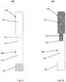
- FIGS. 1A-1B depicts an implant 100.
- Implant 100 is an osteonecrosis head pin or a core decompression implant that includes a first portion 110 and a second portion 120.
- First portion 110 has a substantially cylindrical body 112 and projection 111.
- body 112 may be conically shaped, for example.
- Body 112 preferably has a porous structure that comprises at least an outer surface thereof to allow for bone in-growth therein.
- body 112 may have a solid core with the porous structure surrounding the solid core.
- body 112 may be entirely porous.
- Such porous structure provides stability of implant 100 within the patient. For example, where implant 100 is inserted within a femur, bone tissue from the femoral neck and head can grow into first portion 110 such that implant 100 is more stably held in place and prohibits back-out of such implant 100 from the bone.
- the porosity of the porous structure of body 112 may be about 10% to 90% with an average pore size of between 20-1000 microns.
- body 112 preferably includes a pore size of between 100 and 700 microns with a mean pore size of 400 to 500 microns and a mean porosity of 55% to 65%. Examples of such a porous structure are described in U.S. Pat. Nos. 9,456,901 and 9,135,374 , which are incorporated by reference herein in their entirety.
- body 112 can have either a uniform or varying levels of porosity throughout its porous structure.
- body 112 can have a first internal porosity encompassed by a second surface porosity where the first porosity is greater or smaller than the second porosity.
- first portion 110 is depicted as having rounded edges, in alternative aspects, the distal end of first portion 110 can have a planar or sharp edge.
- Projection 111 extends proximally from a proximal end of body 112 and is configured to be received within second portion 120.
- second portion and first portion may be coupled via press-fit, taper-fit, snap-fit, threaded connection, splined connection, and the like.
- Second portion 120 can also be over-molded onto projection 111.
- projection 111 may be tapered to facilitate a taper-fit connection.
- projection 111 may be cylindrical and have an outer diameter slightly larger than a corresponding opening of second portion 120.
- projection 111 may include one or more threads helically extending along the length thereof for threaded connection with second portion 120.
- projection 111 may include a plurality of splines extending outwardly therefrom for receipt in corresponding recesses in second portion 120.
- Projection 111 preferably has a solid structure to facilitate connection with 120 and to provide strength to such connection.
- first portion 110 is preferably constructed from one or more biocompatible metals, such as but not limited to any one of or any combination of titanium and its alloys, stainless steel and its alloys, magnesium and its alloys, cobalt and its alloys including a cobalt chrome alloy, nickel and its alloys, silver, tantalum, and niobium. It is also contemplated that first portion 110 may be made from one or more biocompatible polymers, such as but not limited to any one of or any combination of polyethylene (PE) and variations thereof, polyetheretherketone (PEEK), polyetherketone (PEK), acrylonitrile butadiene styrene (ABS), silicone, and cross-linked polymers.
- PE polyethylene
- PEEK polyetheretherketone
- PEK polyetherketone
- ABS acrylonitrile butadiene styrene
- silicone silicone
- Second portion 120 is substantially cylindrical, and includes a helical thread 122 at the proximal or trailing end and a recess or opening 121 at the distal end of the second portion 120.
- second portion 120 may be conically-shaped.
- Thread 122 may be self-tapping or otherwise configured to engage the surrounding bone tissue when implant 100 is inserted within the patient.
- Recess 121 is configured and sized to receive projection 111 of first portion 110 so as to couple first and second portions 110, 120.
- Projection 111 can be secured within recess 121 in a variety of ways, as mentioned above. Therefore, recess 121 may configured for any one of such means. For example, where projection 111 is threadably received within recess 121, recess 121 may have corresponding internal threads. Alternatively, recess 121 may be correspondingly tapered or dimensioned for a taper-fit or press-fit connection.
- Second portion 120 is preferably made of a resorbable material such that the entirety of its cross-sectional dimension constitutes a resorbable material. In other words, the entire thickness of second portion 120 is resorbable at at least one location along the length of second portion 120 so that there is no portion of the cross-sectional area at such location that is made from a contaminating debris creating material, such as metal. This allows a surgeon to cut through second portion 120 in a subsequent surgical procedure, after the resorbable material of second portion 120 is fully resorbed or at least partially resorbed, without creating potentially contaminating debris.
- second portion 120 may be made of bioresorbable glass, ceramics, plastics, and biological active materials including collagen/cell matrices. Additional bioresorbable materials may include polylactic acid, polyglycolic acid, magnesium, magnesium alloys, hydroxyapatite, and tricalcium phosphate.
- second portion 120 may be made of a resorbable material while not affecting the basic and novel characteristics of implant 100.
- second portion 120 can define a channel that extends along at least a portion of the length of second portion 120.
- a cross-section of second portion 120 may include a bioresorbable material, such as the materials mentioned above, and an empty region unoccupied by material.
- a core of soft biocompatible material that would not leave any debris when cut can be surrounded by an outer layer of bioresorbable material.
- second portion 120 may be substantially smooth and have no thread, or a plurality of threads.
- thread 122 can be located along any portion of the length of second portion 120 such as, for example, at an intermediate portion or distal end of the second portion.
- second portion 120 can include a recess (not shown) at the proximal end for receiving an instrument, such as a driver. In this manner, the instrument can rotate implant 100 to secure implant 100 to the surrounding bone tissue.
- implant 100 will now be described with reference to FIGS. 2A-2B .
- a channel (not shown) is cut ( e.g., through drilling, broaching, reaming, or the like) into femur 10, through trochanteric region 40 and femoral neck 50, and into femoral head 30.
- Implant 100 is then inserted into the channel leading with first portion 110.
- Implant 100 is then secured to trochanteric region 40 through rotating second portion 120 such that thread 122 engages with the surrounding bone tissue. Over time, bone may grow into the porous structure of first portion 112 to further secure implant 100 to the bone.
- FIG. 2A depicts the final position of implant 100 where first portion 110 lies within femoral head 30, and a first section of second portion 120 lies within trochanteric region 40 and a second section of second portion 120 lies within femoral neck 50.
- the proximal end of implant 100 includes a recess for receiving an instrument (not shown)
- the instrument can rotate second portion 120 to secure implant 100 within femur 10.
- Implant 100 along with the core decompression can help extend the viability of necrotic bone. However, whether through normal cartilage wear or bone deterioration, a hip replacement may be necessary. In such an instance, implant 100 allows for easy removal and implantation of the hip prosthesis.
- second portion 120 is made of a resorbable material, as described above, the second portion 120 may have been partially or fully resorbed into the bone. Thus, only first portion 110 of the original implant 100 may remain. However, even where second portion 120 has not been fully resorbed, its resorbable nature allows it to be easily cut without concerns that leftover debris will contaminate the patient.
- removing implant 100 includes imaging femur 10 to locate first portion 110 within the femur. In this manner, a resection line 20 can be marked on femur 10 via a preoperative plan to cut and remove first portion 110 without cutting into the first portion. The surgeon can then cut along resection line 20 to remove and discard first portion 110 along with femoral head.
- the femur 10 may then be prepared as usual for the hip prosthesis 200 by forming a channel (not shown) in the proximal femur 10 for prosthesis 200. Prosthesis 200 is then inserted into the channel such that stem 220 is received in the channel and ball joint 210 protrudes for engagement with an acetabular cup (not shown).
- Implant 100 helps treat avascular necrosis while eliminating the complexity imposed in subsequent hip replacement procedures by existing core decompression implants. In this regard, the subsequent procedure does not require a lengthy and difficult process to remove implant 100. As such, the surgeon simply resects along line 20, as shown in FIG. 2B and prepares the femur according to the surgeon's normal practice.
Landscapes
- Health & Medical Sciences (AREA)
- Orthopedic Medicine & Surgery (AREA)
- Life Sciences & Earth Sciences (AREA)
- Transplantation (AREA)
- Animal Behavior & Ethology (AREA)
- General Health & Medical Sciences (AREA)
- Biomedical Technology (AREA)
- Heart & Thoracic Surgery (AREA)
- Veterinary Medicine (AREA)
- Engineering & Computer Science (AREA)
- Public Health (AREA)
- Oral & Maxillofacial Surgery (AREA)
- Cardiology (AREA)
- Vascular Medicine (AREA)
- Surgery (AREA)
- Physical Education & Sports Medicine (AREA)
- Neurology (AREA)
- Nuclear Medicine, Radiotherapy & Molecular Imaging (AREA)
- Medical Informatics (AREA)
- Molecular Biology (AREA)
- Prostheses (AREA)
Abstract
A femoral implant including a porous portion configured to be received in a femoral head of a femur and having a leading end and a coupling end disposed opposite the leading end and a resorbable portion configured to be at least partially received within a femoral neck of a femur. The resorbable portion having a trailing end and a coupling end disposed opposite the trailing end, wherein the coupling ends of the porous portion and resorbable portions are coupled together such that the leading end of the porous portion forms a leading end of the femoral implant and the trailing end of the resorbable portion forms a trailing end of the femoral implant and a longitudinal axis of the femoral implant extends through the leading and trailing ends.
Description
- Avascular necrosis, or osteonecrosis, is the death of bone tissue when the blood supply to a portion of the bone has been interrupted or otherwise reduced. Over time, avascular necrosis results in the deterioration of bone tissue that eventually results in structural failure. Early diagnosis allows for the implementation of treatment options that can slow or stop the destruction of the diseased tissue.
- One such treatment option is core decompression. Core decompression is a surgical procedure that involves drilling into necrotic bone to reduce internal pressure and increase blood flow. Avascular necrosis is frequently found in proximal femurs and can result in hip fractures particularly within the femoral head and neck. Core decompression of the proximal femur includes drilling into the femoral head and neck via a lateral side of the femur, and implanting an implant into the drilled hole. Such an implant is generally utilized to provide structural support and may have a porous structure to facilitate blood flow and bone ingrowth.
- While such implants have been suitable for their intended purpose, many patients who undergo core decompression eventually have to undergo hip replacement surgery. However, hip replacement surgery may be hindered by the presence of the core decompression implant as hip replacement procedures often require the femoral head to be removed by cutting through the femoral neck. In this regard, the core decompression implant is a barrier to femoral head resection and, therefore, must be removed. Removal of core decompression implants is difficult, time consuming and can unnecessarily damage portions of the bone surrounding the implant particularly where bone has grown into its porous structure. The other option is to cut through the core decompression implant when resecting the bone. However, this may be difficult, if not impossible, as such implants are typically made from hard metals and would otherwise produce metallic debris that would almost inevitably be left behind in the patient leading to potential complications. Regardless, even where a portion of the implant is cut away along with the femoral head, the remaining portion of the implant would still require removal to make room for the joint prosthesis. Therefore, further improvements are desirable.
- In accordance with an aspect of the disclosure, a method comprising cutting a channel through a femoral neck and into a femoral head of a femur, and inserting a femoral implant within the channel such that a porous portion of the femoral implant is positioned within the femoral head and a resorbable portion of the femoral implant is positioned within the femoral neck, the porous portion being coupled to the resorbable portion and extending therefrom along a longitudinal axis of the femoral implant, the resorbable portion having a cross-sectional area defined in a plane extending transverse to a longitudinal axis of the femoral implant, the cross-sectional area of the resorbable portion consisting essentially of a resorbable material. The porous portion may be inserted such that the porous portion is positioned entirely within the femoral head. The resorbable portion may be inserted such that a length of the resorbable portion is positioned within the trochanteric region of the femur. The method may further comprise securing the femoral implant to the femur by rotatably engaging a helical thread adjacent a trailing end of the resorbable portion with the femur. Securing the femoral implant may include engaging an instrument with the trailing end of the implant, and rotating the instrument to engage the set of threads with the femur. The resorbable material may be selected from one of polylactic acid, polyglycolic acid, magnesium, magnesium alloys, hydroxyapatite, and tricalcium phosphate. The porous portion may be made from one of titanium, stainless steel, cobalt-chromium, and niobium. The porous portion may comprise a porous outer surface having a porosity adapted to promote bony ingrowth.
- In accordance with another aspect of the disclosure, a method comprising cutting a channel through a femoral neck and into a femoral head of a femur, and inserting a femoral implant within the channel such that a first portion of the femoral implant is positioned within the femoral head and a second portion of the femoral implant is positioned within the femoral neck, the first portion comprising a porous material adapted to promote bony ingrowth, and the second portion consisting essentially of a resorbable material. The first portion and second portion may join at an intermediate section of the femoral implant such that the first portion extends from the intermediate section to a distal end of the femoral implant and the second portion extends from the intermediate section to a proximal end of the femoral implant. The inserting step may include threadedly engaging the femur with a thread of the femoral implant. The thread may be disposed along the second portion. The inserting step may include engaging recess at the proximal end of the femoral implant with an instrument and rotating the femoral implant within the channel via the instrument. The first portion may be made from one of titanium, stainless steel, cobalt-chromium, and niobium. The resorbable portion may be made from one of polylactic acid, polyglycolic acid, magnesium, magnesium alloys, hydroxyapatite, and tricalcium phosphate. The first portion may have a projection extending partially into the second portion so as to secure the first portion to the second portion.
- In accordance with yet another aspect of the disclosure, a method of preparing a femur for a joint prosthesis after a femoral implant had been implanted to treat avascular necrosis, comprising cutting through a femoral neck of a femur and an area of the femoral neck where a portion of a previously implanted femoral implant has been at least partially resorbed within the femoral neck so as to remove a femoral head of the femur and a porous portion of the femoral implant disposed within the femoral head, cutting through a trochanteric region of the femur and into an intramedullary canal thereof to form a channel for a joint prosthesis, and inserting a stem of a joint prosthesis within the channel. Cutting through the femoral neck region may include resecting a femoral head containing the porous portion of the femoral implant without contacting the porous portion. Cutting through the trochanteric region may include removing at least a portion of the femoral neck where the portion of the previously implanted femoral implant has been at least partially resorbed within the femoral neck.
- In yet another aspect of the disclosure, a femoral implant comprising a porous portion configured to be received in a femoral head of a femur and having a leading end and a coupling end disposed opposite the leading end, and a resorbable portion configured to be at least partially received within a femoral neck of a femur, the resorbable portion having a trailing end and a coupling end disposed opposite the trailing end, wherein the coupling ends of the porous portion and resorbable portions are coupled together such that the leading end of the porous portion forms a leading end of the femoral implant and the trailing end of the resorbable portion forms a trailing end of the femoral implant and a longitudinal axis of the femoral implant extends through the leading and trailing ends. The resorbable portion may have at least one helical thread adjacent the trailing end. The trailing end may define an instrument recess configured to receive a driver tool. An exterior surface of the porous portion may have a porous structure adapted to promote bony ingrowth therein. The porous portion and the resorbable portion are cylindrical and may have a same outer diameter. The porous portion may include a projection the coupling end and the resorbable portion has a coupling recess at its coupling end, the projection being receivable within the recess so as to secure the porous portion to the resorbable portion. The projection may be at least one of press-fit, taper-fit, snap-fit, threaded connection, or splined connection within the coupling recess. The porous portion may have a first section and a second section, the first and second sections having different porosities. The porous portion may be made from a metallic material and the resorbable portion is made from a bioresorbable plastic.
- In a yet further aspect of the disclosure, a method of treating avascular necrosis of a femur comprising in a first surgical procedure, inserting a femoral implant through a trochanteric region of the femur such that a first portion of the implant is positioned within the femoral head and a second portion of the femoral implant is positioned within a femoral neck of the femur, and in a second surgical procedure, cutting through the femoral neck and the second portion of the femoral implant so as to remove the femoral head along with the first portion of the femoral implant to prepare the bone for a hip prosthesis. The first portion comprises a porous material and the second portion may comprise a resorbable material.
- In accordance with another aspect of the disclosure, a femoral implant comprising a porous portion configured to be received in a femoral head of a femur and having a leading end and a coupling end disposed opposite the leading end, and a resorbable portion configured to be at least partially received within a femoral neck of a femur, the resorbable portion having a trailing end and a coupling end disposed opposite the trailing end, wherein the coupling ends of the porous portion and resorbable portions are coupled together such that the leading end of the porous portion forms a leading end of the femoral implant and the trailing end of the resorbable portion forms a trailing end of the femoral implant and a longitudinal axis of the femoral implant extends through the leading and trailing ends. The resorbable portion can have at least one helical thread adjacent the trailing end. The trailing end can define a tool recess configured to receive a driver tool. An exterior surface of the porous portion can have a porous structure adapted to promote bony ingrowth therein. The porous portion and the resorbable portion can be cylindrical and have a same outer diameter. The porous portion can include a protrusion the coupling end and the resorbable portion has a coupling recess at its coupling end, the protrusion being receivable within the recess so as to secure the porous portion to the resorbable portion. The protrusion can include at least one of threadably received, snap fit, or press fit within the coupling recess. The porous portion can have a first section and a second section, the first and second sections having different porosities. The porous portion can be made from a metallic material and the resorbable portion is made from a bioresorbable plastic.
- These and other features, aspects, and advantages of the present invention will become better understood with regard to the following description, and accompanying drawings.
-
FIG. 1A is a partial transparent front view of an implant according to one aspect of the present disclosure. -
FIG. 1B is a cross-sectional view of the implant ofFIG. 1 taken along a midline thereof. -
FIGS. 2A-2B depicts the method of implanting the implant ofFIG. 1 and subsequently implanting a joint prosthesis according to an aspect of the present disclosure. - As used herein, when referring to the femur or other parts of the body, the term "proximal" means closer to the heart, and the term "distal" means more distant from the heart. The term "inferior" means toward the feet of a patient, and the term "superior" means towards the head of the patient. The term "anterior" means towards the front part of the body or the face, and the term "posterior" means towards the back of the body. The term "medial" means toward the midline of the body, and the term "lateral" means away from the midline of the body. When referring to an implantable device, the term "proximal" means closer to the surgeon, while the term "distal" means further from the surgeon.
-
FIGS. 1A-1B depicts animplant 100.Implant 100 is an osteonecrosis head pin or a core decompression implant that includes afirst portion 110 and asecond portion 120.First portion 110 has a substantiallycylindrical body 112 andprojection 111. However, in some embodiments,body 112 may be conically shaped, for example.Body 112 preferably has a porous structure that comprises at least an outer surface thereof to allow for bone in-growth therein. In this regard,body 112 may have a solid core with the porous structure surrounding the solid core. However, in some embodiments,body 112 may be entirely porous. Such porous structure provides stability ofimplant 100 within the patient. For example, whereimplant 100 is inserted within a femur, bone tissue from the femoral neck and head can grow intofirst portion 110 such thatimplant 100 is more stably held in place and prohibits back-out ofsuch implant 100 from the bone. - In the embodiment depicted in
FIGS. 1A-1B , the porosity of the porous structure ofbody 112 may be about 10% to 90% with an average pore size of between 20-1000 microns. However,body 112 preferably includes a pore size of between 100 and 700 microns with a mean pore size of 400 to 500 microns and a mean porosity of 55% to 65%. Examples of such a porous structure are described inU.S. Pat. Nos. 9,456,901 9,135,374 body 112 can have either a uniform or varying levels of porosity throughout its porous structure. For example,body 112 can have a first internal porosity encompassed by a second surface porosity where the first porosity is greater or smaller than the second porosity. Although a distal or leading end offirst portion 110 is depicted as having rounded edges, in alternative aspects, the distal end offirst portion 110 can have a planar or sharp edge. -
Projection 111 extends proximally from a proximal end ofbody 112 and is configured to be received withinsecond portion 120. As described below, second portion and first portion may be coupled via press-fit, taper-fit, snap-fit, threaded connection, splined connection, and the like.Second portion 120 can also be over-molded ontoprojection 111. In this regard, in one embodiment,projection 111 may be tapered to facilitate a taper-fit connection. In another embodiment,projection 111 may be cylindrical and have an outer diameter slightly larger than a corresponding opening ofsecond portion 120. In an even further embodiment,projection 111 may include one or more threads helically extending along the length thereof for threaded connection withsecond portion 120. In a yet further embodiment,projection 111 may include a plurality of splines extending outwardly therefrom for receipt in corresponding recesses insecond portion 120.Projection 111 preferably has a solid structure to facilitate connection with 120 and to provide strength to such connection. - Each of solid and porous layers of
first portion 110 is preferably constructed from one or more biocompatible metals, such as but not limited to any one of or any combination of titanium and its alloys, stainless steel and its alloys, magnesium and its alloys, cobalt and its alloys including a cobalt chrome alloy, nickel and its alloys, silver, tantalum, and niobium. It is also contemplated thatfirst portion 110 may be made from one or more biocompatible polymers, such as but not limited to any one of or any combination of polyethylene (PE) and variations thereof, polyetheretherketone (PEEK), polyetherketone (PEK), acrylonitrile butadiene styrene (ABS), silicone, and cross-linked polymers. -
Second portion 120 is substantially cylindrical, and includes ahelical thread 122 at the proximal or trailing end and a recess or opening 121 at the distal end of thesecond portion 120. However, in some embodiments,second portion 120 may be conically-shaped.Thread 122 may be self-tapping or otherwise configured to engage the surrounding bone tissue whenimplant 100 is inserted within the patient.Recess 121 is configured and sized to receiveprojection 111 offirst portion 110 so as to couple first andsecond portions Projection 111 can be secured withinrecess 121 in a variety of ways, as mentioned above. Therefore,recess 121 may configured for any one of such means. For example, whereprojection 111 is threadably received withinrecess 121,recess 121 may have corresponding internal threads. Alternatively,recess 121 may be correspondingly tapered or dimensioned for a taper-fit or press-fit connection. -
Second portion 120 is preferably made of a resorbable material such that the entirety of its cross-sectional dimension constitutes a resorbable material. In other words, the entire thickness ofsecond portion 120 is resorbable at at least one location along the length ofsecond portion 120 so that there is no portion of the cross-sectional area at such location that is made from a contaminating debris creating material, such as metal. This allows a surgeon to cut throughsecond portion 120 in a subsequent surgical procedure, after the resorbable material ofsecond portion 120 is fully resorbed or at least partially resorbed, without creating potentially contaminating debris. In some arrangements,second portion 120 may be made of bioresorbable glass, ceramics, plastics, and biological active materials including collagen/cell matrices. Additional bioresorbable materials may include polylactic acid, polyglycolic acid, magnesium, magnesium alloys, hydroxyapatite, and tricalcium phosphate. - However it is contemplated that only a portion of the cross-section of
second portion 120 may be made of a resorbable material while not affecting the basic and novel characteristics ofimplant 100. For instance,second portion 120 can define a channel that extends along at least a portion of the length ofsecond portion 120. In this regard, a cross-section ofsecond portion 120 may include a bioresorbable material, such as the materials mentioned above, and an empty region unoccupied by material. In an alternative aspect, it is contemplated that a core of soft biocompatible material that would not leave any debris when cut can be surrounded by an outer layer of bioresorbable material. - Moreover, in alternative aspects,
second portion 120 may be substantially smooth and have no thread, or a plurality of threads. In a further alternative aspect,thread 122 can be located along any portion of the length ofsecond portion 120 such as, for example, at an intermediate portion or distal end of the second portion. In a yet further alternative aspect,second portion 120 can include a recess (not shown) at the proximal end for receiving an instrument, such as a driver. In this manner, the instrument can rotateimplant 100 to secureimplant 100 to the surrounding bone tissue. - The use of
implant 100 will now be described with reference toFIGS. 2A-2B . A channel (not shown) is cut (e.g., through drilling, broaching, reaming, or the like) intofemur 10, throughtrochanteric region 40 and femoral neck 50, and intofemoral head 30.Implant 100 is then inserted into the channel leading withfirst portion 110.Implant 100 is then secured totrochanteric region 40 through rotatingsecond portion 120 such thatthread 122 engages with the surrounding bone tissue. Over time, bone may grow into the porous structure offirst portion 112 to furthersecure implant 100 to the bone.FIG. 2A depicts the final position ofimplant 100 wherefirst portion 110 lies withinfemoral head 30, and a first section ofsecond portion 120 lies withintrochanteric region 40 and a second section ofsecond portion 120 lies within femoral neck 50. Where the proximal end ofimplant 100 includes a recess for receiving an instrument (not shown), the instrument can rotatesecond portion 120 to secureimplant 100 withinfemur 10. -
Implant 100 along with the core decompression can help extend the viability of necrotic bone. However, whether through normal cartilage wear or bone deterioration, a hip replacement may be necessary. In such an instance,implant 100 allows for easy removal and implantation of the hip prosthesis. - In this regard, where
second portion 120 is made of a resorbable material, as described above, thesecond portion 120 may have been partially or fully resorbed into the bone. Thus, onlyfirst portion 110 of theoriginal implant 100 may remain. However, even wheresecond portion 120 has not been fully resorbed, its resorbable nature allows it to be easily cut without concerns that leftover debris will contaminate the patient. In this case, removingimplant 100 includesimaging femur 10 to locatefirst portion 110 within the femur. In this manner, aresection line 20 can be marked onfemur 10 via a preoperative plan to cut and removefirst portion 110 without cutting into the first portion. The surgeon can then cut alongresection line 20 to remove and discardfirst portion 110 along with femoral head. Referring toFIG. 2B , thefemur 10 may then be prepared as usual for thehip prosthesis 200 by forming a channel (not shown) in theproximal femur 10 forprosthesis 200.Prosthesis 200 is then inserted into the channel such that stem 220 is received in the channel and ball joint 210 protrudes for engagement with an acetabular cup (not shown). - Previous methods of removing an implant within the femur required carefully cutting the bone tissue around the implant to remove the implant to minimize the chances of accidentally cutting into the implant and leaving metal debris within the patient. As previously described, this increases the surgical complexity of dealing with avascular necrosis.
Implant 100 helps treat avascular necrosis while eliminating the complexity imposed in subsequent hip replacement procedures by existing core decompression implants. In this regard, the subsequent procedure does not require a lengthy and difficult process to removeimplant 100. As such, the surgeon simply resects alongline 20, as shown inFIG. 2B and prepares the femur according to the surgeon's normal practice. - Although the invention herein has been described with reference to particular embodiments, it is to be understood that these embodiments are merely illustrative of the principles and applications of the present invention. It is therefore to be understood that numerous modifications may be made to the illustrative embodiments and that other arrangements may be devised without departing from the spirit and scope of the present invention as defined by the appended claims.
Claims (9)
- A femoral implant comprising:a porous portion configured to be received in a femoral head of a femur and having a leading end and a coupling end disposed opposite the leading end; anda resorbable portion configured to be at least partially received within a femoral neck of a femur, the resorbable portion having a trailing end and a coupling end disposed opposite the trailing end,wherein the coupling ends of the porous portion and resorbable portions are coupled together such that the leading end of the porous portion forms a leading end of the femoral implant and the trailing end of the resorbable portion forms a trailing end of the femoral implant and a longitudinal axis of the femoral implant extends through the leading and trailing ends.
- The femoral implant of claim 1, wherein the resorbable portion has at least one helical thread adjacent the trailing end.
- The femoral implant of any one of claims 1 and 2, wherein the trailing end defines a tool recess configured to receive a driver tool.
- The femoral implant of any one of claims 1 to 3, wherein an exterior surface of the porous portion has a porous structure adapted to promote bony ingrowth therein.
- The femoral implant of any one of claims 1 to 4, wherein the porous portion and the resorbable portion are cylindrical and have a same outer diameter.
- The femoral implant of any one of claims 1 to 5, wherein the porous portion includes a protrusion the coupling end and the resorbable portion has a coupling recess at its coupling end, the protrusion being receivable within the recess so as to secure the porous portion to the resorbable portion.
- The femoral implant of claim 6, wherein the protrusion is at least one of threadably received, snap fit, or press fit within the coupling recess.
- The femoral implant of any one of claims 1 to 7, wherein the porous portion has a first section and a second section, the first and second sections having different porosities.
- The femoral implant of any one of claims 1 to 8, wherein the porous portion is made from a metallic material and the resorbable portion is made from a bioresorbable plastic.
Applications Claiming Priority (1)
| Application Number | Priority Date | Filing Date | Title |
|---|---|---|---|
| US202062964330P | 2020-01-22 | 2020-01-22 |
Publications (1)
| Publication Number | Publication Date |
|---|---|
| EP3854333A1 true EP3854333A1 (en) | 2021-07-28 |
Family
ID=74215717
Family Applications (1)
| Application Number | Title | Priority Date | Filing Date |
|---|---|---|---|
| EP21153004.3A Withdrawn EP3854333A1 (en) | 2020-01-22 | 2021-01-22 | Femoral implant |
Country Status (3)
| Country | Link |
|---|---|
| US (1) | US12029660B2 (en) |
| EP (1) | EP3854333A1 (en) |
| AU (1) | AU2021200320B2 (en) |
Families Citing this family (1)
| Publication number | Priority date | Publication date | Assignee | Title |
|---|---|---|---|---|
| CN113520513B (en) * | 2021-06-16 | 2023-02-28 | 叶川 | Bone-taking and pressure-reducing bone grafting device capable of protecting hip through percutaneous minimally invasive precise positioning |
Citations (6)
| Publication number | Priority date | Publication date | Assignee | Title |
|---|---|---|---|---|
| WO1993017639A1 (en) * | 1992-03-12 | 1993-09-16 | Kampner Stanley L | Implant with reinforced resorbable stem |
| US6471707B1 (en) * | 2001-05-11 | 2002-10-29 | Biomet | Bone screw having bioresorbable proximal shaft portion |
| EP1297794A2 (en) * | 2001-09-28 | 2003-04-02 | Ethicon, Inc. | Self-tapping resorbable two-piece bone screw |
| WO2009055952A1 (en) * | 2007-10-30 | 2009-05-07 | Woodwelding Ag | Method and device for producing an anchorage in human or animal tissue |
| US9135374B2 (en) | 2012-04-06 | 2015-09-15 | Howmedica Osteonics Corp. | Surface modified unit cell lattice structures for optimized secure freeform fabrication |
| US9456901B2 (en) | 2004-12-30 | 2016-10-04 | Howmedica Osteonics Corp. | Laser-produced porous structure |
Family Cites Families (22)
| Publication number | Priority date | Publication date | Assignee | Title |
|---|---|---|---|---|
| US4990161A (en) * | 1984-03-16 | 1991-02-05 | Kampner Stanley L | Implant with resorbable stem |
| US5306311A (en) * | 1987-07-20 | 1994-04-26 | Regen Corporation | Prosthetic articular cartilage |
| US20020032488A1 (en) * | 1994-05-13 | 2002-03-14 | Brekke John H. | Device for regeneration of articular cartilage and other tissue |
| US7077867B1 (en) * | 1994-08-12 | 2006-07-18 | Diamicron, Inc. | Prosthetic knee joint having at least one diamond articulation surface |
| WO1996039974A1 (en) | 1995-06-07 | 1996-12-19 | Implex Corporation | Femoral head core channel filling prosthesis |
| DE19652608C1 (en) * | 1996-12-18 | 1998-08-27 | Eska Implants Gmbh & Co | Prophylaxis implant against fractures of osteoporotically affected bone segments |
| US6511481B2 (en) * | 2001-03-30 | 2003-01-28 | Triage Medical, Inc. | Method and apparatus for fixation of proximal femoral fractures |
| US7488320B2 (en) * | 2001-11-01 | 2009-02-10 | Renova Orthopedics, Llc | Orthopaedic implant fixation using an in-situ formed anchor |
| US7094236B2 (en) * | 2003-03-25 | 2006-08-22 | Marc Waisman | Hybrid interlocking proximal femoral fracture fixation |
| JP2006528515A (en) * | 2003-07-24 | 2006-12-21 | テコメット・インコーポレーテッド | Spongy structure |
| US7189263B2 (en) * | 2004-02-03 | 2007-03-13 | Vita Special Purpose Corporation | Biocompatible bone graft material |
| US7217283B2 (en) * | 2004-12-30 | 2007-05-15 | Depuy Products, Inc. | Orthopaedic implant for vascularization of the femoral head |
| WO2007038560A1 (en) | 2005-09-28 | 2007-04-05 | Smith & Nephew, Inc. | Instrumentation for reducing fractures , particularly femoral neck |
| US9370427B2 (en) | 2007-04-13 | 2016-06-21 | Christopher G. Sidebotham | Bone-compliant femoral stem |
| US20090043397A1 (en) * | 2007-08-10 | 2009-02-12 | Park Hyung-Bae | Modular Femoral Head Surface Replacement, Modular Femoral Neck Stem, and Related Sleeve, Adapter, and Osteoconducting Rod |
| US8556972B2 (en) | 2009-04-02 | 2013-10-15 | Sevika Holding AG | Monolithic orthopedic implant with an articular finished surface |
| US8470049B2 (en) * | 2009-09-01 | 2013-06-25 | Concept, Design And Development, Llc | Neck sparing total hip implant system |
| US8579947B2 (en) | 2009-09-14 | 2013-11-12 | Yangguan Wu | Polyporous hollow bone screw |
| WO2013106318A1 (en) | 2012-01-09 | 2013-07-18 | Zimmer, Inc. | Composite device that combines porous metal and bone stimuli |
| US9427319B2 (en) * | 2012-08-27 | 2016-08-30 | Robert R. Gray | Vascularized porous metal orthopaedic implant devices |
| WO2016154063A1 (en) | 2015-03-20 | 2016-09-29 | The Board Of Trustees Of The Leland Stanford Junior Univeristy | Customized load-bearing and bioactive functionally-graded implant for treatment of osteonecrosis |
| CN107582218A (en) * | 2017-10-09 | 2018-01-16 | 北京爱康宜诚医疗器材有限公司 | Pattern of fusion femoral stem system |
-
2021
- 2021-01-19 AU AU2021200320A patent/AU2021200320B2/en active Active
- 2021-01-21 US US17/154,662 patent/US12029660B2/en active Active
- 2021-01-22 EP EP21153004.3A patent/EP3854333A1/en not_active Withdrawn
Patent Citations (6)
| Publication number | Priority date | Publication date | Assignee | Title |
|---|---|---|---|---|
| WO1993017639A1 (en) * | 1992-03-12 | 1993-09-16 | Kampner Stanley L | Implant with reinforced resorbable stem |
| US6471707B1 (en) * | 2001-05-11 | 2002-10-29 | Biomet | Bone screw having bioresorbable proximal shaft portion |
| EP1297794A2 (en) * | 2001-09-28 | 2003-04-02 | Ethicon, Inc. | Self-tapping resorbable two-piece bone screw |
| US9456901B2 (en) | 2004-12-30 | 2016-10-04 | Howmedica Osteonics Corp. | Laser-produced porous structure |
| WO2009055952A1 (en) * | 2007-10-30 | 2009-05-07 | Woodwelding Ag | Method and device for producing an anchorage in human or animal tissue |
| US9135374B2 (en) | 2012-04-06 | 2015-09-15 | Howmedica Osteonics Corp. | Surface modified unit cell lattice structures for optimized secure freeform fabrication |
Also Published As
| Publication number | Publication date |
|---|---|
| US12029660B2 (en) | 2024-07-09 |
| US20210220150A1 (en) | 2021-07-22 |
| AU2021200320A1 (en) | 2021-08-05 |
| AU2021200320B2 (en) | 2026-03-26 |
Similar Documents
| Publication | Publication Date | Title |
|---|---|---|
| US7641699B2 (en) | Femoral head calcar loading prosthesis | |
| EP1138284B1 (en) | Femoral hip prothesis | |
| JP6529717B2 (en) | System and method for implanting a second glenoid prosthesis | |
| Lee | The current concepts of total hip arthroplasty | |
| US8936649B2 (en) | Orthopaedic hip prosthesis having femoral stem components with varying A/P taper angles | |
| EP1858452B1 (en) | Long sleeves for use with stems | |
| EP1138283A2 (en) | Femoral hip prosthesis | |
| US20180000598A1 (en) | Hip stem | |
| WO2014151602A1 (en) | Removable augment for medical implant | |
| Morscher et al. | Cementless fixation of polyethylene acetabular component in total hip arthroplasty | |
| JP4397597B2 (en) | Cement plug method | |
| US10603178B2 (en) | Prosthetic hip system | |
| US12029660B2 (en) | Femoral implant | |
| CN106798600B (en) | Combined rack | |
| AU2016353265B2 (en) | Joint implants and methods | |
| US12121446B1 (en) | Modular implant for combination hip replacement with intramedullary rod | |
| CN214017991U (en) | A porous ring-shaped prosthesis for cancellous bone reconstruction | |
| WO2022099491A1 (en) | Prosthesis for cancellous bone reconstruction | |
| US20160270932A1 (en) | Long bone resurfacing bone lock | |
| Steno et al. | Minimally invasive hollow trephine technique is recommended for revision of broken uncemented and extensively porous-coated monolithic femoral stems: a review of three cases | |
| CN112245068A (en) | Spongy bone reconstruction porous ring-shaped prosthesis | |
| RU237262U1 (en) | PROXIMAL FEMORAL COMPONENT OF THE ENDOPROSTHESIS | |
| US20240252217A1 (en) | Kit for the installation of prosthetic components and/or biomedical implants | |
| WO2012079618A1 (en) | An orthopaedic implant and an orthopaedic implant system incorporating same | |
| Koch | Surgical Treatment Methods of Hip Joint Dysplasia in Dogs |
Legal Events
| Date | Code | Title | Description |
|---|---|---|---|
| PUAI | Public reference made under article 153(3) epc to a published international application that has entered the european phase |
Free format text: ORIGINAL CODE: 0009012 |
|
| STAA | Information on the status of an ep patent application or granted ep patent |
Free format text: STATUS: REQUEST FOR EXAMINATION WAS MADE |
|
| 17P | Request for examination filed |
Effective date: 20210122 |
|
| AK | Designated contracting states |
Kind code of ref document: A1 Designated state(s): AL AT BE BG CH CY CZ DE DK EE ES FI FR GB GR HR HU IE IS IT LI LT LU LV MC MK MT NL NO PL PT RO RS SE SI SK SM TR |
|
| STAA | Information on the status of an ep patent application or granted ep patent |
Free format text: STATUS: THE APPLICATION IS DEEMED TO BE WITHDRAWN |
|
| 18D | Application deemed to be withdrawn |
Effective date: 20220129 |