EP3854289A1 - Dishwashing machine - Google Patents
Dishwashing machine Download PDFInfo
- Publication number
- EP3854289A1 EP3854289A1 EP19916577.0A EP19916577A EP3854289A1 EP 3854289 A1 EP3854289 A1 EP 3854289A1 EP 19916577 A EP19916577 A EP 19916577A EP 3854289 A1 EP3854289 A1 EP 3854289A1
- Authority
- EP
- European Patent Office
- Prior art keywords
- heat exchange
- communicating component
- cold storage
- washing
- heat
- Prior art date
- Legal status (The legal status is an assumption and is not a legal conclusion. Google has not performed a legal analysis and makes no representation as to the accuracy of the status listed.)
- Pending
Links
Images


Classifications
-
- A—HUMAN NECESSITIES
- A47—FURNITURE; DOMESTIC ARTICLES OR APPLIANCES; COFFEE MILLS; SPICE MILLS; SUCTION CLEANERS IN GENERAL
- A47L—DOMESTIC WASHING OR CLEANING; SUCTION CLEANERS IN GENERAL
- A47L15/00—Washing or rinsing machines for crockery or tableware
- A47L15/14—Washing or rinsing machines for crockery or tableware with stationary crockery baskets and spraying devices within the cleaning chamber
- A47L15/16—Washing or rinsing machines for crockery or tableware with stationary crockery baskets and spraying devices within the cleaning chamber with rigidly-mounted spraying devices
-
- A—HUMAN NECESSITIES
- A47—FURNITURE; DOMESTIC ARTICLES OR APPLIANCES; COFFEE MILLS; SPICE MILLS; SUCTION CLEANERS IN GENERAL
- A47L—DOMESTIC WASHING OR CLEANING; SUCTION CLEANERS IN GENERAL
- A47L15/00—Washing or rinsing machines for crockery or tableware
- A47L15/42—Details
- A47L15/4291—Recovery arrangements, e.g. for the recovery of energy or water
-
- A—HUMAN NECESSITIES
- A47—FURNITURE; DOMESTIC ARTICLES OR APPLIANCES; COFFEE MILLS; SPICE MILLS; SUCTION CLEANERS IN GENERAL
- A47L—DOMESTIC WASHING OR CLEANING; SUCTION CLEANERS IN GENERAL
- A47L15/00—Washing or rinsing machines for crockery or tableware
- A47L15/42—Details
-
- A—HUMAN NECESSITIES
- A47—FURNITURE; DOMESTIC ARTICLES OR APPLIANCES; COFFEE MILLS; SPICE MILLS; SUCTION CLEANERS IN GENERAL
- A47L—DOMESTIC WASHING OR CLEANING; SUCTION CLEANERS IN GENERAL
- A47L15/00—Washing or rinsing machines for crockery or tableware
- A47L15/42—Details
- A47L15/4278—Nozzles
-
- D—TEXTILES; PAPER
- D06—TREATMENT OF TEXTILES OR THE LIKE; LAUNDERING; FLEXIBLE MATERIALS NOT OTHERWISE PROVIDED FOR
- D06F—LAUNDERING, DRYING, IRONING, PRESSING OR FOLDING TEXTILE ARTICLES
- D06F39/00—Details of washing machines not specific to a single type of machines covered by groups D06F9/00 - D06F27/00
- D06F39/04—Heating arrangements
-
- F—MECHANICAL ENGINEERING; LIGHTING; HEATING; WEAPONS; BLASTING
- F24—HEATING; RANGES; VENTILATING
- F24H—FLUID HEATERS, e.g. WATER OR AIR HEATERS, HAVING HEAT-GENERATING MEANS, e.g. HEAT PUMPS, IN GENERAL
- F24H4/00—Fluid heaters characterised by the use of heat pumps
- F24H4/02—Water heaters
-
- F—MECHANICAL ENGINEERING; LIGHTING; HEATING; WEAPONS; BLASTING
- F25—REFRIGERATION OR COOLING; COMBINED HEATING AND REFRIGERATION SYSTEMS; HEAT PUMP SYSTEMS; MANUFACTURE OR STORAGE OF ICE; LIQUEFACTION SOLIDIFICATION OF GASES
- F25B—REFRIGERATION MACHINES, PLANTS OR SYSTEMS; COMBINED HEATING AND REFRIGERATION SYSTEMS; HEAT PUMP SYSTEMS
- F25B30/00—Heat pumps
- F25B30/02—Heat pumps of the compression type
-
- F—MECHANICAL ENGINEERING; LIGHTING; HEATING; WEAPONS; BLASTING
- F25—REFRIGERATION OR COOLING; COMBINED HEATING AND REFRIGERATION SYSTEMS; HEAT PUMP SYSTEMS; MANUFACTURE OR STORAGE OF ICE; LIQUEFACTION SOLIDIFICATION OF GASES
- F25B—REFRIGERATION MACHINES, PLANTS OR SYSTEMS; COMBINED HEATING AND REFRIGERATION SYSTEMS; HEAT PUMP SYSTEMS
- F25B39/00—Evaporators; Condensers
- F25B39/02—Evaporators
-
- F—MECHANICAL ENGINEERING; LIGHTING; HEATING; WEAPONS; BLASTING
- F25—REFRIGERATION OR COOLING; COMBINED HEATING AND REFRIGERATION SYSTEMS; HEAT PUMP SYSTEMS; MANUFACTURE OR STORAGE OF ICE; LIQUEFACTION SOLIDIFICATION OF GASES
- F25B—REFRIGERATION MACHINES, PLANTS OR SYSTEMS; COMBINED HEATING AND REFRIGERATION SYSTEMS; HEAT PUMP SYSTEMS
- F25B41/00—Fluid-circulation arrangements
-
- F—MECHANICAL ENGINEERING; LIGHTING; HEATING; WEAPONS; BLASTING
- F28—HEAT EXCHANGE IN GENERAL
- F28D—HEAT-EXCHANGE APPARATUS, NOT PROVIDED FOR IN ANOTHER SUBCLASS, IN WHICH THE HEAT-EXCHANGE MEDIA DO NOT COME INTO DIRECT CONTACT
- F28D20/00—Heat storage plants or apparatus in general; Regenerative heat-exchange apparatus not covered by groups F28D17/00 or F28D19/00
-
- F—MECHANICAL ENGINEERING; LIGHTING; HEATING; WEAPONS; BLASTING
- F28—HEAT EXCHANGE IN GENERAL
- F28D—HEAT-EXCHANGE APPARATUS, NOT PROVIDED FOR IN ANOTHER SUBCLASS, IN WHICH THE HEAT-EXCHANGE MEDIA DO NOT COME INTO DIRECT CONTACT
- F28D20/00—Heat storage plants or apparatus in general; Regenerative heat-exchange apparatus not covered by groups F28D17/00 or F28D19/00
- F28D20/0034—Heat storage plants or apparatus in general; Regenerative heat-exchange apparatus not covered by groups F28D17/00 or F28D19/00 using liquid heat storage material
-
- A—HUMAN NECESSITIES
- A47—FURNITURE; DOMESTIC ARTICLES OR APPLIANCES; COFFEE MILLS; SPICE MILLS; SUCTION CLEANERS IN GENERAL
- A47L—DOMESTIC WASHING OR CLEANING; SUCTION CLEANERS IN GENERAL
- A47L15/00—Washing or rinsing machines for crockery or tableware
- A47L15/42—Details
- A47L15/4285—Water-heater arrangements
-
- Y—GENERAL TAGGING OF NEW TECHNOLOGICAL DEVELOPMENTS; GENERAL TAGGING OF CROSS-SECTIONAL TECHNOLOGIES SPANNING OVER SEVERAL SECTIONS OF THE IPC; TECHNICAL SUBJECTS COVERED BY FORMER USPC CROSS-REFERENCE ART COLLECTIONS [XRACs] AND DIGESTS
- Y02—TECHNOLOGIES OR APPLICATIONS FOR MITIGATION OR ADAPTATION AGAINST CLIMATE CHANGE
- Y02B—CLIMATE CHANGE MITIGATION TECHNOLOGIES RELATED TO BUILDINGS, e.g. HOUSING, HOUSE APPLIANCES OR RELATED END-USER APPLICATIONS
- Y02B30/00—Energy efficient heating, ventilation or air conditioning [HVAC]
- Y02B30/52—Heat recovery pumps, i.e. heat pump based systems or units able to transfer the thermal energy from one area of the premises or part of the facilities to a different one, improving the overall efficiency
-
- Y—GENERAL TAGGING OF NEW TECHNOLOGICAL DEVELOPMENTS; GENERAL TAGGING OF CROSS-SECTIONAL TECHNOLOGIES SPANNING OVER SEVERAL SECTIONS OF THE IPC; TECHNICAL SUBJECTS COVERED BY FORMER USPC CROSS-REFERENCE ART COLLECTIONS [XRACs] AND DIGESTS
- Y02—TECHNOLOGIES OR APPLICATIONS FOR MITIGATION OR ADAPTATION AGAINST CLIMATE CHANGE
- Y02B—CLIMATE CHANGE MITIGATION TECHNOLOGIES RELATED TO BUILDINGS, e.g. HOUSING, HOUSE APPLIANCES OR RELATED END-USER APPLICATIONS
- Y02B40/00—Technologies aiming at improving the efficiency of home appliances, e.g. induction cooking or efficient technologies for refrigerators, freezers or dish washers
-
- Y—GENERAL TAGGING OF NEW TECHNOLOGICAL DEVELOPMENTS; GENERAL TAGGING OF CROSS-SECTIONAL TECHNOLOGIES SPANNING OVER SEVERAL SECTIONS OF THE IPC; TECHNICAL SUBJECTS COVERED BY FORMER USPC CROSS-REFERENCE ART COLLECTIONS [XRACs] AND DIGESTS
- Y02—TECHNOLOGIES OR APPLICATIONS FOR MITIGATION OR ADAPTATION AGAINST CLIMATE CHANGE
- Y02E—REDUCTION OF GREENHOUSE GAS [GHG] EMISSIONS, RELATED TO ENERGY GENERATION, TRANSMISSION OR DISTRIBUTION
- Y02E60/00—Enabling technologies; Technologies with a potential or indirect contribution to GHG emissions mitigation
- Y02E60/14—Thermal energy storage
Definitions
- the present disclosure relates to the field of household machines, and more particularly to a washing appliance.
- a condenser when a dishwasher adopts heat-pump heating technology, a condenser is usually directly connected to a water flow system of the dishwasher. During the washing process, the washing water directly passes through the condenser and is circulated to be heated to a specified temperature to achieve the high-temperature washing of the tableware.
- the heat exchange efficiency between the evaporator and the air is low when the heat-pump technology is adopted, as a result, the washing water cannot be heated sufficiently.
- the cold energy generated during the working process of the heat pump system is discharged by the fan in the form of cold air after the heat exchange, which easily causes a decrease in the temperature of the kitchen, and the noise of the fan is large, which affects the user experience.
- the present disclosure provides a washing appliance.
- the washing appliance including: a washing system and a heat pump system.
- the washing system includes a cavity.
- the heat pump system includes a first heat exchange device, a compressor, a second heat exchange device, and a throttling device.
- the first heat exchange device includes a first communicating component and a second communicating component, the first communicating component, the compressor, the second heat exchange device, and the throttling device are sequentially connected to form a closed circuit in which refrigerant flows.
- the second communicating component is connected to the first communicating component to perform convective heat exchange with the refrigerant in the first communicating component, and the second heat exchange device is configured to perform heat exchange with a pipeline of the washing system to heat washing liquid entering the cavity.
- the second communicating component and the first communicating component use convective heat exchange, so that the heat exchange efficiency is high.
- the refrigerant in the first communicating component fully absorbs heat and vaporizes into low-pressure vapor, and then the compressor can compress the above low-pressure vapor into the high-temperature and high-pressure vapor, and the above high-temperature and high-pressure vapor enters the second heat exchange device to realize fully heating of the washing liquid of the washing system.
- the cold energy generated during the working process of the heat pump system after heat exchange does not need to be discharged in the form of cold air through a fan, which will not cause the temperature of the kitchen to decrease, reduce noise, and improve user experience.
- the heat pump system includes a cold storage device.
- the cold storage device is provided with a cold storage agent.
- the first heat exchange device is arranged in the cold storage device.
- the cold storage device is configured to perform heat exchange with the refrigerant in the first communicating component through the cold storage agent.
- the cold storage device is a water tank, and the cold storage agent is water.
- the first communicating component is immersed in the cold storage agent.
- the heat pump system comprises a circulating pump
- the second communicating component is in communication with an inside of the cold storage device
- the circulating pump is connected to the second communicating component and the cold storage device through a pipe connection to circulate the cold storage agent.
- a flow direction of the liquid in the second communicating component is opposite to a flow direction of the refrigerant in the first communicating component.
- the first communicating component defines a first cavity therein, and the second communicating component is at least partially located in the first cavity.
- the second communicating component has a tubular structure, and the part of the second communicating component located in the first cavity is bent.
- the washing appliance includes a third heat exchange device, the third heat exchange device is connected to the second communicating component and the cold storage device through a pipe connection, and the third heat exchange device is configured to perform heat exchange between the cold storage agent flowing through the third heat exchange device and air.
- the washing appliance includes a fan device, and the fan device is used for cooling the third heat exchange device.
- washing appliance 100 washing system 10, cavity 11, water cup 111, washing pump 12, spray arm assembly 13, pipeline 14, heat pump system 20, first heat exchange device 21, first communicating component 211, first housing 2110, first cavity 2111, second communicating component 212, compressor 22, second heat exchange device 23, third communicating component 231, second housing 2310, second cavity 2311, fourth communicating component 232, throttling device 24, cold storage device 25, case 251, circulating pump 26, third heat exchange device 30, fan device 31.
- relative terms such as "central,” “longitudinal,” “lateral,” “length,” “width,” “thickness,” “upper,” “lower,” “front,” “rear,” “left,” “right,” “vertical,” “horizontal,” “top,” “bottom,” “inner,” “outer,” “clockwise,” “counterclockwise,” and the like should be constructed to refer to the orientation or position as then described or as shown in the drawings under discussion. These relative terms are for convenience and simplification of description and do not indicate or imply that the device or element referred to must have a particular orientation, or be constructed and operated in a particular orientation, so these terms shall not be construed to limit the present disclosure.
- first,” “second,” are used for descriptive purpose only, and cannot be construed to indicate or imply relative importance or implicitly indicate the number of technical features indicated. Therefore, the features defined with “first,” “second,” can explicitly or implicitly include at least one of the features.
- the term “a plurality of' means at least two, for example, two, three, and the like, unless specified or limited otherwise.
- the terms “mounted,” “connected,” “coupled,” and variations thereof should be understood broadly. For example, these may be permanent connections, detachable connections or integrated; mechanical connections, electrical connections, direct connections or indirect connections via intervening structures; inner communication or interaction of two elements. Those skilled in the related art may understand specific meanings of the above terms in the present disclosure according to specific situations.
- a washing appliance 100 of the embodiments of the present disclosure includes a washing system 10 and a heat pump system 20.
- the washing appliance 100 is a dishwasher. It can be understood that the washing appliance can also be other appliances that use water, such as a clothes washing machine.
- the washing system 10 includes a cavity 11 and a washing pump 12.
- the washing pump 12 is connected to the cavity 11 through a pipe connection.
- the heat pump system 20 includes a first heat exchange device 21, a compressor 22, a second heat exchange device 23, and a throttling device 24.
- the first heat exchange device 21 includes a first communicating component 211 and a second communicating component 212.
- the first communicating component 211, the compressor 22, the second heat exchange device 23, and the throttling device 24 are connected sequentially to from a closed circuit in which refrigerant flows.
- the second communicating component 212 is connected to the first communicating component 211 to perform convective heat exchange with the refrigerant in the first communicating component 211.
- the second heat exchange device 23 is configured to perform heat exchange with a pipeline of the washing system 10 to heat washing liquid entering the cavity 11.
- the first heat exchange device 21 when the heat pump system 20 operates, the first heat exchange device 21 is used as an evaporator, and the refrigerant in the first communicating component 211 is vaporized into low-pressure vapor by absorbing the heat.
- a heat exchange mode between the second communicating component 212 and the first communicating component 211 is an indirect heat exchange.
- a flow direction of the liquid (for example, water) in the second communicating component 212 is opposite to a flow direction of the refrigerant in the first communicating component 211 to realize convective heat exchange between the second communicating component 212 and the first communicating component 211.
- the compressor 22 can compress the above low-pressure vapor into a high-temperature and high-pressure vapor.
- the second heat exchange device 23 is used as a condenser, and the heat of the high-temperature and high-pressure vapor in the second heat exchange device 23 is transferred to the pipeline of the washing system 10 to heat the washing liquid of the washing system 10.
- the throttling device 24 is used to throttle the above high-temperature and high-pressure vapor after heat exchange into a low-temperature and low-pressure liquid.
- the above low-temperature and low-pressure liquid flows back to the first communicating component 211 to absorb heat again to evaporate, and the next cycle begins.
- the washing pump 12 can pump the heated washing liquid into the cavity 11 to clean the tableware located in the cavity 11. It can be understood that the washing liquid may be water or a mixed liquid of water and detergent.
- first communicating component can include one or more first heat exchange tubes
- second communicating component can include one or more second heat exchange tubes.
- the first heat exchange tube and the second heat exchange tube can employ a structure of concentric tubes to promote the convective heat exchange between the first communicating component and the second communicating component.
- the connection mode of the first communicating component 211 and the second communicating component 212 of this embodiment is described in detail below.
- the washing system 10 includes a spray arm assembly 13.
- the washing pump 12 is separately connected to the cavity 11 and the spray arm assembly 13 through the pipeline 14.
- a water cup 111 is formed at a lower part of the cavity 11 for collecting the washing liquid in the cavity 11.
- the spray arm assembly 13 is arranged in the cavity 11, the washing pump 12 is arranged outside the cavity 11, and the washing pump 12 is connected to the water cup 111 and the spray arm assembly 13 through the pipeline 14.
- the heat pump system 20 starts to operate, and the heat of the high-temperature and high-pressure vapor in the second heat exchange device 23 is transferred to the pipeline of the washing system 10 to heat the washing liquid of the washing system 10.
- the heated washing liquid is conveyed to the respective spray arms of the spray arm assembly 13 through the pipeline 14 under the pumping action of the washing pump 12.
- the spray arm assembly 13 has a spray arm.
- the number of spray arms of the spray arm assembly 13 can be specifically adjusted, which is not specifically limited herein.
- the washing appliance 100 is a dishwasher, which has a spray arm assembly 13.
- the washing appliance 100 may be an appliance that uses water such as a clothes washing machine, and the clothes washing machine can omit the spray arm assembly.
- the compressor 22 can be a horizontal compressor or a vertical compressor
- the second heat exchange device can be a condenser or a condensing tube, which is not specifically limited and can be determined according to actual conditions.
- the throttling device 24 includes an expansion valve.
- the low-temperature and high-pressure liquid refrigerant formed after being condensed by the second heat exchange device 23 becomes a low-temperature and low-pressure mist hydraulic refrigerant after being throttled by the orifice of the expansion valve, creating conditions for the evaporation of the refrigerant.
- the throttling device 24 can also be of other types, such as a capillary tube, etc., which is not specifically limited.
- the second communicating component 212 and the first communicating component 211 use a convective heat exchange, so that the heat exchange efficiency is high.
- the refrigerant in the first communicating component 211 fully absorbs heat and vaporizes into low-pressure vapor, and then the compressor 22 can compress the above low-pressure vapor into the high-temperature and high-pressure vapor, and the above high-temperature and high-pressure vapor enters the second heat exchange device 23 to realize fully heating of the washing liquid of the washing system 10.
- the cold energy generated during the working process of the heat pump system 20 after heat exchange does not need to be discharged in the form of cold air through a fan, which will not cause the temperature of the kitchen to decrease, reduce noise, and improve the user experience.
- the heat pump system 20 includes a cold storage device 25.
- the cold storage device 25 is provided with a cold storage agent (not illustrated).
- the first heat exchange device 21 is arranged in the cold storage device 25.
- the cold storage device 25 is configured to perform heat exchange with the refrigerant in the first communicating component 211 through the cold storage agent. In this way, the area of heat exchange between the refrigerant of the first communicating component 211 and the outside can be increased, and the latent heat in the cold storage agent can be effectively used, that is, the refrigerant in the first communicating component 211 can also effectively absorb the heat in the cold storage agent.
- the cold storage agent is water or a cold storage material.
- the cold storage device 25 is a water tank, and the cold storage agent is water.
- the first heat exchange device 21 is immersed in the cold storage agent. In this way, the area of heat exchange between the cold storage device 25 and the first communicating component 211 is large, and the latent heat in the cold storage agent can be fully utilized effectively. In addition, the first heat exchange device 21 is immersed in the cold storage agent, which can also prevent the outside of the first communicating component 211 from freezing.
- the heat pump system 20 includes a circulating pump 26.
- the second communicating component 212 is in communication with an inside of the cold storage device 25.
- the circulating pump 26 is connected to the second communicating component 212 and the cold storage device 25 through a pipe connection to circulate the cold storage agent.
- the cold storage device 25 includes a case 251.
- the cold storage agent is provided in the case 251.
- the circulating pump 26 is located outside the case 251.
- the first heat exchange device 21 is arranged in the case 251.
- the cold storage agent inside the case 251 can quickly flow through the second communicating component 212 under the pumping action of the circulating pump 26 and then return to the cold storage device 25 (as illustrated by the arrows in FIGS. 2 and 3 ), the heat exchange efficiency between the refrigerant in the first communicating component 211 and the cold storage agent can be enhanced, and the heat exchange area of the first heat exchange device 21 can be greatly reduced.
- the first communicating component and the second communicating component employ a tubular structure, the length of the pipeline of the first heat exchange device can also be shortened, so that the design of the first heat exchange device is more compact.
- the first communicating component 211 defines a first cavity 2111 therein.
- the second communicating component 212 is at least partially located in the first cavity 2111.
- the first communicating component 211 has a first housing 2110.
- the first housing 2110 defines the first cavity 2111 therein.
- the first housing 2110 can be made of corrosion and high-pressure resistant materials.
- the second communicating component 212 may adopt a tubular structure, and the second communicating component 212 is resistant to corrosion and high pressure. At least part of the second communicating component 212 is located in the first cavity 2111.
- the low-temperature and low-pressure gas-liquid two-phase refrigerant flows into the first cavity 2111, and can exchange heat with the cold storage agent in the case 251 through a wall of the first housing 2110, and can also perform a forced convective heat exchange with the cold storage agent in the second communicating component 212 through a wall surface of the second communicating component 212.
- the internal refrigerant of the first communicating component 211 releases cold energy into the cold storage agent amount in two directions, so that the low-temperature and low-pressure gas-liquid two-phase refrigerant flowing from the throttling device 24 quickly vaporizes into a superheated gaseous refrigerant and flows into the compressor 22.
- the volume of the first cavity 2111 can be adjusted by controlling an outer diameter of the second communicating component 212 and an inner diameter of the first housing 2110.
- the first heat exchange device 21 of this embodiment does not cause an increase in filling volume of the refrigerant of the heat pump system 20.
- the first heat exchange device 21 of this embodiment not only can reduce the refrigerant charge, but also can reduce the pressure drop of the first heat exchange device 21 to a certain extent, so that the heating efficiency of the heat pump system 20 can be increased.
- the second communicating component 212 has a tubular structure, and a part of the second communicating component 212 located in the first cavity 2111 is bent. In this way, the area for heat exchange between the second communicating component 212 and the first communicating component 211 can be increased.
- the second heat exchange device 23 includes a third communicating component 231 and a fourth communicating component 232.
- the first communicating component 211, the compressor 22, the third communicating component 231, and the throttling device 24 are sequentially connected to form a closed circuit in which the refrigerant flows.
- the third communicating component 231 exchanges heat with the pipeline of the washing system 10 through the fourth communicating component 232.
- the third communicating component 231 is heat-conductively connected to the fourth communicating component 232, and the high-temperature and high-pressure vapor compressed by the compressor 22 enters the third communicating component 231 to perform indirect heat exchange with the liquid (for example, the washing liquid) in the fourth communicating component 232 to heat the washing liquid in the pipeline of the washing system 10, so that the heat exchange efficiency is high.
- the third communicating component 231 defines a second cavity 2311 therein.
- the fourth communicating component 231 is at least partially located in the second cavity 2311.
- the third communicating component 231 has a second housing 2310.
- the second housing 2310 defines a second cavity 3111 therein.
- the second housing 2310 can be made of corrosion and high-pressure resistant materials.
- the fourth communicating component 232 may adopt a tubular structure, and the fourth communicating component 232 is resistant to corrosion and high pressure. At least part of the fourth communicating component 232 is located in the second cavity 3111.
- the high-temperature and high-pressure vapor compressed by the compressor 22 enters the third communicating component 231, and can perform forced convective heat exchange with the cold storage agent in the fourth communicating component 232 through the wall surface of the fourth communicating component 232 (as illustrated in FIG. 2 and as illustrated by arrows in FIG. 2 ).
- the part of the third communicating component 231 located in the second cavity 2311 may be bent.
- the washing machine 100 includes a third heat exchange device 30.
- the third heat exchange device 30 is connected to the second communicating component 212 and the cold storage device 25 through a pipe connection.
- the third heat exchange device 30 is configured to exchange heat between the cold storage agent flowing through the third heat exchange device 30 and air.
- the third heat exchange device 30 may be directly connected to the cold storage device 25 and the second communicating component 212, or may be indirectly connected to the cold storage device 25 and the second communicating component 212.
- the pipeline at an end of the circulating pump 26 is in communication with the case 251
- the pipeline at the other end of the circulating pump 26 is in communication with the second communicating component 212.
- the cold storage agent inside the case 251 can flow out of the case 251 under the pumping action of the circulating pump 26, and exchange heat with the air through the third heat exchange device 30 to absorb the heat of the air.
- the temperature difference between the cold storage agent and the refrigerant in the tank 251 can be increased.
- the washing machine 100 includes a fan device 31.
- the fan device 31 is used to cool the third heat exchange device 30.
- the provision of the fan device 31 can improve the efficiency of heat exchange between the cold storage agent flowing through the third heat exchange device 30 and the air.
- a structure in which a first feature is “on” or “below” a second feature may include an embodiment in which the first feature is in direct contact with the second feature, and may also include an embodiment in which the first feature is in indirect contact with the second feature through intermediaries.
- a first feature "on,” “above,” or “on top of' a second feature may include an embodiment in which the first feature is right “on,” “above,” or “on top of' the second feature, and may also include an embodiment in which the first feature is diagonally “on,” “above,” or “on top of' the second feature, or just means that the first feature is at a height higher than that of the second feature.
- a first feature "beneath,” “below,” or “on bottom of' a second feature may include an embodiment in which the first feature is right “beneath,” “below,” or “on bottom of' the second feature, and may also include an embodiment in which the first feature is diagonally “beneath,” “below,” or “on bottom of' the second feature, or just means that the first feature is at a height lower than that of the second feature.
- the present disclosure provides many different embodiments or examples for realizing different structures of the present disclosure.
- the components and arrangements of specific examples are described herein. Of course, they are only examples, and are not intended to limit the present disclosure.
- the present disclosure may repeat reference numerals and/or reference letters in different examples, and this repetition is for the purpose of simplification and clarity, and does not indicate the relationship between the various embodiments and/or arrangements discussed.
- the present disclosure provides examples of various specific processes and materials, but those of ordinary skill in the art may be aware of the application of other processes and/or the use of other materials.
Landscapes
- Engineering & Computer Science (AREA)
- Physics & Mathematics (AREA)
- Thermal Sciences (AREA)
- Mechanical Engineering (AREA)
- General Engineering & Computer Science (AREA)
- Chemical & Material Sciences (AREA)
- Combustion & Propulsion (AREA)
- Textile Engineering (AREA)
- Heat-Pump Type And Storage Water Heaters (AREA)
- Washing And Drying Of Tableware (AREA)
Abstract
Description
- This application claims priority to and benefits of
Chinese Patent Application No. 201910138756.5 - The present disclosure relates to the field of household machines, and more particularly to a washing appliance.
- In the related art, when a dishwasher adopts heat-pump heating technology, a condenser is usually directly connected to a water flow system of the dishwasher. During the washing process, the washing water directly passes through the condenser and is circulated to be heated to a specified temperature to achieve the high-temperature washing of the tableware. However, in the related art to heat the heat exchange efficiency between the evaporator and the air is low when the heat-pump technology is adopted, as a result, the washing water cannot be heated sufficiently. In addition, the cold energy generated during the working process of the heat pump system is discharged by the fan in the form of cold air after the heat exchange, which easily causes a decrease in the temperature of the kitchen, and the noise of the fan is large, which affects the user experience.
- The present disclosure provides a washing appliance.
- The washing appliance according to the embodiments of the present disclosure, including:
a washing system and a heat pump system. The washing system includes a cavity. The heat pump system includes a first heat exchange device, a compressor, a second heat exchange device, and a throttling device. The first heat exchange device includes a first communicating component and a second communicating component, the first communicating component, the compressor, the second heat exchange device, and the throttling device are sequentially connected to form a closed circuit in which refrigerant flows. The second communicating component is connected to the first communicating component to perform convective heat exchange with the refrigerant in the first communicating component, and the second heat exchange device is configured to perform heat exchange with a pipeline of the washing system to heat washing liquid entering the cavity. - In the above-described washing appliance, the second communicating component and the first communicating component use convective heat exchange, so that the heat exchange efficiency is high. When the washing water needs to be heated, the refrigerant in the first communicating component fully absorbs heat and vaporizes into low-pressure vapor, and then the compressor can compress the above low-pressure vapor into the high-temperature and high-pressure vapor, and the above high-temperature and high-pressure vapor enters the second heat exchange device to realize fully heating of the washing liquid of the washing system. In addition, the cold energy generated during the working process of the heat pump system after heat exchange does not need to be discharged in the form of cold air through a fan, which will not cause the temperature of the kitchen to decrease, reduce noise, and improve user experience.
- In some embodiments, the heat pump system includes a cold storage device. The cold storage device is provided with a cold storage agent. The first heat exchange device is arranged in the cold storage device. The cold storage device is configured to perform heat exchange with the refrigerant in the first communicating component through the cold storage agent.
- In some embodiments, the cold storage device is a water tank, and the cold storage agent is water.
- In some embodiments, the first communicating component is immersed in the cold storage agent.
- In some embodiments, the heat pump system comprises a circulating pump, the second communicating component is in communication with an inside of the cold storage device, and the circulating pump is connected to the second communicating component and the cold storage device through a pipe connection to circulate the cold storage agent.
- In some embodiments, a flow direction of the liquid in the second communicating component is opposite to a flow direction of the refrigerant in the first communicating component.
- In some embodiments, the first communicating component defines a first cavity therein, and the second communicating component is at least partially located in the first cavity.
- In some embodiments, the second communicating component has a tubular structure, and the part of the second communicating component located in the first cavity is bent.
- In some embodiments, the washing appliance includes a third heat exchange device, the third heat exchange device is connected to the second communicating component and the cold storage device through a pipe connection, and the third heat exchange device is configured to perform heat exchange between the cold storage agent flowing through the third heat exchange device and air.
- In some embodiments, the washing appliance includes a fan device, and the fan device is used for cooling the third heat exchange device.
- Additional aspects and advantages of embodiments of present disclosure will be given in part in the following descriptions, become apparent in part from the following descriptions, or be learned from the practice of the embodiments of the present disclosure.
- These above and/or additional aspects and advantages of embodiments of the present disclosure will become apparent and more readily appreciated from the following descriptions made with reference to the accompanying drawings, in which:
-
FIG. 1 is a schematic structural view of a washing appliance according to an embodiment of the present disclosure; -
FIG. 2 is a schematic structural view of a heat pump system of a washing appliance according to an embodiment of the present disclosure; and -
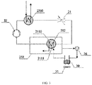
FIG. 3 is another schematic structural view of the heat pump system of the washing appliance according to an embodiment of the present disclosure. - Symbol description of main elements:
washing appliance 100,washing system 10,cavity 11,water cup 111,washing pump 12,spray arm assembly 13,pipeline 14,heat pump system 20, firstheat exchange device 21, first communicatingcomponent 211,first housing 2110,first cavity 2111, second communicatingcomponent 212,compressor 22, secondheat exchange device 23, third communicatingcomponent 231,second housing 2310,second cavity 2311, fourth communicatingcomponent 232,throttling device 24,cold storage device 25,case 251, circulatingpump 26, thirdheat exchange device 30,fan device 31. - Embodiments of the present application will be described in detail below, and the examples of the embodiments will be illustrated in the drawings. The same or similar elements and the elements having same or similar functions are denoted by like reference numerals throughout the description. The embodiments described herein with reference to the drawings are illustrative and used to generally understand the present disclosure. The embodiments shall not be construed to limit the present disclosure.
- In the description of the present disclosure, relative terms such as "central," "longitudinal," "lateral," "length," "width," "thickness," "upper," "lower," "front," "rear," "left," "right," "vertical," "horizontal," "top," "bottom," "inner," "outer," "clockwise," "counterclockwise," and the like should be constructed to refer to the orientation or position as then described or as shown in the drawings under discussion. These relative terms are for convenience and simplification of description and do not indicate or imply that the device or element referred to must have a particular orientation, or be constructed and operated in a particular orientation, so these terms shall not be construed to limit the present disclosure. Furthermore, terms "first," "second," are used for descriptive purpose only, and cannot be construed to indicate or imply relative importance or implicitly indicate the number of technical features indicated. Therefore, the features defined with "first," "second," can explicitly or implicitly include at least one of the features. In the description of the present disclosure, the term "a plurality of' means at least two, for example, two, three, and the like, unless specified or limited otherwise.
- In the descriptions, unless specified or limited otherwise, the terms "mounted," "connected," "coupled," and variations thereof should be understood broadly. For example, these may be permanent connections, detachable connections or integrated; mechanical connections, electrical connections, direct connections or indirect connections via intervening structures; inner communication or interaction of two elements. Those skilled in the related art may understand specific meanings of the above terms in the present disclosure according to specific situations.
- Referring to
FIG. 1 , a washing appliance 100 of the embodiments of the present disclosure includes awashing system 10 and aheat pump system 20. For example, the washing appliance 100 is a dishwasher. It can be understood that the washing appliance can also be other appliances that use water, such as a clothes washing machine. - Referring to
FIG. 1 , thewashing system 10 includes acavity 11 and awashing pump 12. Thewashing pump 12 is connected to thecavity 11 through a pipe connection. Theheat pump system 20 includes a firstheat exchange device 21, acompressor 22, a secondheat exchange device 23, and athrottling device 24. The firstheat exchange device 21 includes a first communicatingcomponent 211 and a second communicatingcomponent 212. The first communicatingcomponent 211, thecompressor 22, the secondheat exchange device 23, and thethrottling device 24 are connected sequentially to from a closed circuit in which refrigerant flows. The second communicatingcomponent 212 is connected to the first communicatingcomponent 211 to perform convective heat exchange with the refrigerant in the first communicatingcomponent 211. The secondheat exchange device 23 is configured to perform heat exchange with a pipeline of thewashing system 10 to heat washing liquid entering thecavity 11. - Specifically, when the
heat pump system 20 operates, the firstheat exchange device 21 is used as an evaporator, and the refrigerant in the first communicatingcomponent 211 is vaporized into low-pressure vapor by absorbing the heat. A heat exchange mode between the second communicatingcomponent 212 and the first communicatingcomponent 211 is an indirect heat exchange. A flow direction of the liquid (for example, water) in the second communicatingcomponent 212 is opposite to a flow direction of the refrigerant in the first communicatingcomponent 211 to realize convective heat exchange between the second communicatingcomponent 212 and the first communicatingcomponent 211. Thecompressor 22 can compress the above low-pressure vapor into a high-temperature and high-pressure vapor. The secondheat exchange device 23 is used as a condenser, and the heat of the high-temperature and high-pressure vapor in the secondheat exchange device 23 is transferred to the pipeline of thewashing system 10 to heat the washing liquid of thewashing system 10. The throttlingdevice 24 is used to throttle the above high-temperature and high-pressure vapor after heat exchange into a low-temperature and low-pressure liquid. The above low-temperature and low-pressure liquid flows back to the first communicatingcomponent 211 to absorb heat again to evaporate, and the next cycle begins. Thewashing pump 12 can pump the heated washing liquid into thecavity 11 to clean the tableware located in thecavity 11. It can be understood that the washing liquid may be water or a mixed liquid of water and detergent. - It can be understood that the first communicating component can include one or more first heat exchange tubes, and the second communicating component can include one or more second heat exchange tubes. The first heat exchange tube and the second heat exchange tube can employ a structure of concentric tubes to promote the convective heat exchange between the first communicating component and the second communicating component. The connection mode of the first communicating
component 211 and the second communicatingcomponent 212 of this embodiment is described in detail below. - Referring to
FIG. 1 , thewashing system 10 includes aspray arm assembly 13. Thewashing pump 12 is separately connected to thecavity 11 and thespray arm assembly 13 through thepipeline 14. Awater cup 111 is formed at a lower part of thecavity 11 for collecting the washing liquid in thecavity 11. Thespray arm assembly 13 is arranged in thecavity 11, thewashing pump 12 is arranged outside thecavity 11, and thewashing pump 12 is connected to thewater cup 111 and thespray arm assembly 13 through thepipeline 14. When the washing appliance 100 is used for washing, thewashing system 10 is started, and thewashing pump 12 continuously conveys the washing liquid in thewater cup 111 to the respective spray arms of thespray arm assembly 13 through thepipeline 14, so as to achieve the purpose of cleaning items (as illustrated by the arrows on the pipeline of thewashing system 10 inFIG. 1 ). When hot water is needed for washing, theheat pump system 20 starts to operate, and the heat of the high-temperature and high-pressure vapor in the secondheat exchange device 23 is transferred to the pipeline of thewashing system 10 to heat the washing liquid of thewashing system 10. The heated washing liquid is conveyed to the respective spray arms of thespray arm assembly 13 through thepipeline 14 under the pumping action of thewashing pump 12. - In an example illustrated in
FIG. 1 , thespray arm assembly 13 has a spray arm. In other embodiments, the number of spray arms of thespray arm assembly 13 can be specifically adjusted, which is not specifically limited herein. In the example of the present disclosure, the washing appliance 100 is a dishwasher, which has aspray arm assembly 13. In other examples, the washing appliance 100 may be an appliance that uses water such as a clothes washing machine, and the clothes washing machine can omit the spray arm assembly. - It should be noted that the
compressor 22 can be a horizontal compressor or a vertical compressor, and the second heat exchange device can be a condenser or a condensing tube, which is not specifically limited and can be determined according to actual conditions. - The throttling
device 24 includes an expansion valve. The low-temperature and high-pressure liquid refrigerant formed after being condensed by the secondheat exchange device 23 becomes a low-temperature and low-pressure mist hydraulic refrigerant after being throttled by the orifice of the expansion valve, creating conditions for the evaporation of the refrigerant. Of course, the throttlingdevice 24 can also be of other types, such as a capillary tube, etc., which is not specifically limited. - In summary, the second communicating
component 212 and the first communicatingcomponent 211 use a convective heat exchange, so that the heat exchange efficiency is high. When the washing water needs to be heated, the refrigerant in the first communicatingcomponent 211 fully absorbs heat and vaporizes into low-pressure vapor, and then thecompressor 22 can compress the above low-pressure vapor into the high-temperature and high-pressure vapor, and the above high-temperature and high-pressure vapor enters the secondheat exchange device 23 to realize fully heating of the washing liquid of thewashing system 10. In addition, the cold energy generated during the working process of theheat pump system 20 after heat exchange does not need to be discharged in the form of cold air through a fan, which will not cause the temperature of the kitchen to decrease, reduce noise, and improve the user experience. In some embodiments, theheat pump system 20 includes acold storage device 25. Thecold storage device 25 is provided with a cold storage agent (not illustrated). The firstheat exchange device 21 is arranged in thecold storage device 25. Thecold storage device 25 is configured to perform heat exchange with the refrigerant in the first communicatingcomponent 211 through the cold storage agent. In this way, the area of heat exchange between the refrigerant of the first communicatingcomponent 211 and the outside can be increased, and the latent heat in the cold storage agent can be effectively used, that is, the refrigerant in the first communicatingcomponent 211 can also effectively absorb the heat in the cold storage agent. - It should be noted that, for example, the cold storage agent is water or a cold storage material. In some examples, the
cold storage device 25 is a water tank, and the cold storage agent is water. - In some embodiments, the first
heat exchange device 21 is immersed in the cold storage agent. In this way, the area of heat exchange between thecold storage device 25 and the first communicatingcomponent 211 is large, and the latent heat in the cold storage agent can be fully utilized effectively. In addition, the firstheat exchange device 21 is immersed in the cold storage agent, which can also prevent the outside of the first communicatingcomponent 211 from freezing. - Referring to
FIGS. 2 and3 , in some embodiments, theheat pump system 20 includes a circulatingpump 26. The second communicatingcomponent 212 is in communication with an inside of thecold storage device 25. The circulatingpump 26 is connected to the second communicatingcomponent 212 and thecold storage device 25 through a pipe connection to circulate the cold storage agent. - Specifically, the
cold storage device 25 includes acase 251. The cold storage agent is provided in thecase 251. The circulatingpump 26 is located outside thecase 251. The firstheat exchange device 21 is arranged in thecase 251. The cold storage agent inside thecase 251 can quickly flow through the second communicatingcomponent 212 under the pumping action of the circulatingpump 26 and then return to the cold storage device 25 (as illustrated by the arrows inFIGS. 2 and3 ), the heat exchange efficiency between the refrigerant in the first communicatingcomponent 211 and the cold storage agent can be enhanced, and the heat exchange area of the firstheat exchange device 21 can be greatly reduced. When the first communicating component and the second communicating component employ a tubular structure, the length of the pipeline of the first heat exchange device can also be shortened, so that the design of the first heat exchange device is more compact. - In some embodiments, the first communicating
component 211 defines afirst cavity 2111 therein. The second communicatingcomponent 212 is at least partially located in thefirst cavity 2111. - Specifically, the first communicating
component 211 has afirst housing 2110. Thefirst housing 2110 defines thefirst cavity 2111 therein. Thefirst housing 2110 can be made of corrosion and high-pressure resistant materials. The second communicatingcomponent 212 may adopt a tubular structure, and the second communicatingcomponent 212 is resistant to corrosion and high pressure. At least part of the second communicatingcomponent 212 is located in thefirst cavity 2111. After being throttled by the throttlingdevice 24, the low-temperature and low-pressure gas-liquid two-phase refrigerant flows into thefirst cavity 2111, and can exchange heat with the cold storage agent in thecase 251 through a wall of thefirst housing 2110, and can also perform a forced convective heat exchange with the cold storage agent in the second communicatingcomponent 212 through a wall surface of the second communicatingcomponent 212. Under this heat exchange, the internal refrigerant of the first communicatingcomponent 211 releases cold energy into the cold storage agent amount in two directions, so that the low-temperature and low-pressure gas-liquid two-phase refrigerant flowing from the throttlingdevice 24 quickly vaporizes into a superheated gaseous refrigerant and flows into thecompressor 22. - It can be understood that when the
first housing 2110 has a tubular structure and the second communicatingcomponent 212 has a tubular structure, the volume of thefirst cavity 2111 can be adjusted by controlling an outer diameter of the second communicatingcomponent 212 and an inner diameter of thefirst housing 2110. The firstheat exchange device 21 of this embodiment does not cause an increase in filling volume of the refrigerant of theheat pump system 20. The firstheat exchange device 21 of this embodiment not only can reduce the refrigerant charge, but also can reduce the pressure drop of the firstheat exchange device 21 to a certain extent, so that the heating efficiency of theheat pump system 20 can be increased. - In some embodiments, the second communicating
component 212 has a tubular structure, and a part of the second communicatingcomponent 212 located in thefirst cavity 2111 is bent. In this way, the area for heat exchange between the second communicatingcomponent 212 and the first communicatingcomponent 211 can be increased. - In some embodiments, the second
heat exchange device 23 includes a third communicatingcomponent 231 and a fourth communicatingcomponent 232. The first communicatingcomponent 211, thecompressor 22, the third communicatingcomponent 231, and thethrottling device 24 are sequentially connected to form a closed circuit in which the refrigerant flows. The third communicatingcomponent 231 exchanges heat with the pipeline of thewashing system 10 through the fourth communicatingcomponent 232. The third communicatingcomponent 231 is heat-conductively connected to the fourth communicatingcomponent 232, and the high-temperature and high-pressure vapor compressed by thecompressor 22 enters the third communicatingcomponent 231 to perform indirect heat exchange with the liquid (for example, the washing liquid) in the fourth communicatingcomponent 232 to heat the washing liquid in the pipeline of thewashing system 10, so that the heat exchange efficiency is high. - In some embodiments, the third communicating
component 231 defines asecond cavity 2311 therein. The fourth communicatingcomponent 231 is at least partially located in thesecond cavity 2311. - The third communicating
component 231 has asecond housing 2310. Thesecond housing 2310 defines a second cavity 3111 therein. Thesecond housing 2310 can be made of corrosion and high-pressure resistant materials. The fourth communicatingcomponent 232 may adopt a tubular structure, and the fourth communicatingcomponent 232 is resistant to corrosion and high pressure. At least part of the fourth communicatingcomponent 232 is located in the second cavity 3111. The high-temperature and high-pressure vapor compressed by thecompressor 22 enters the third communicatingcomponent 231, and can perform forced convective heat exchange with the cold storage agent in the fourth communicatingcomponent 232 through the wall surface of the fourth communicating component 232 (as illustrated inFIG. 2 and as illustrated by arrows inFIG. 2 ). - It can be understood that, in order to increase the heat exchange area, the part of the third communicating
component 231 located in thesecond cavity 2311 may be bent. - Referring to
FIG. 3 , in some embodiments, the washing machine 100 includes a thirdheat exchange device 30. The thirdheat exchange device 30 is connected to the second communicatingcomponent 212 and thecold storage device 25 through a pipe connection. The thirdheat exchange device 30 is configured to exchange heat between the cold storage agent flowing through the thirdheat exchange device 30 and air. - It should be noted that the third
heat exchange device 30 may be directly connected to thecold storage device 25 and the second communicatingcomponent 212, or may be indirectly connected to thecold storage device 25 and the second communicatingcomponent 212. In the example illustrated inFIG. 3 , the pipeline at an end of the circulatingpump 26 is in communication with thecase 251, and the pipeline at the other end of the circulatingpump 26 is in communication with the second communicatingcomponent 212. The cold storage agent inside thecase 251 can flow out of thecase 251 under the pumping action of the circulatingpump 26, and exchange heat with the air through the thirdheat exchange device 30 to absorb the heat of the air. The temperature difference between the cold storage agent and the refrigerant in thetank 251 can be increased. - Referring to
FIG. 3 , in some embodiments, the washing machine 100 includes afan device 31. Thefan device 31 is used to cool the thirdheat exchange device 30. The provision of thefan device 31 can improve the efficiency of heat exchange between the cold storage agent flowing through the thirdheat exchange device 30 and the air. - In the present disclosure, unless specified or limited otherwise, a structure in which a first feature is "on" or "below" a second feature may include an embodiment in which the first feature is in direct contact with the second feature, and may also include an embodiment in which the first feature is in indirect contact with the second feature through intermediaries. Furthermore, a first feature "on," "above," or "on top of' a second feature may include an embodiment in which the first feature is right "on," "above," or "on top of' the second feature, and may also include an embodiment in which the first feature is diagonally "on," "above," or "on top of' the second feature, or just means that the first feature is at a height higher than that of the second feature. A first feature "beneath," "below," or "on bottom of' a second feature may include an embodiment in which the first feature is right "beneath," "below," or "on bottom of' the second feature, and may also include an embodiment in which the first feature is diagonally "beneath," "below," or "on bottom of' the second feature, or just means that the first feature is at a height lower than that of the second feature.
- The present disclosure provides many different embodiments or examples for realizing different structures of the present disclosure. In order to simplify the disclosure of the present disclosure, the components and arrangements of specific examples are described herein. Of course, they are only examples, and are not intended to limit the present disclosure. In addition, the present disclosure may repeat reference numerals and/or reference letters in different examples, and this repetition is for the purpose of simplification and clarity, and does not indicate the relationship between the various embodiments and/or arrangements discussed. In addition, the present disclosure provides examples of various specific processes and materials, but those of ordinary skill in the art may be aware of the application of other processes and/or the use of other materials.
- In the description of the present specification, reference throughout this specification to "an embodiment," "some embodiments," "an exemplary embodiment", "an example," "a specific example," or "some examples" means that a particular feature, structure, material, or characteristic described in connection with the embodiment or example is included in at least one embodiment or example of the present disclosure. In the specification, the appearances of the above-mentioned terms are not necessarily referring to the same embodiment or example of the present disclosure. Furthermore, the particular features, structures, materials, or characteristics may be combined in any suitable manner in one or more embodiments or examples.
- Although embodiments of the present disclosure have been shown and described, it shall be appreciated by those skilled in the art that various changes, modifications, alternatives, and variations can be made in the embodiments without departing from principles and purposes of the present disclosure. The scope of the present disclosure is defined by claims or their equivalents.
Claims (10)
- A washing appliance, comprising:a washing system comprising a cavity;a heat pump system comprising a first heat exchange device, a compressor, a second heat exchange device, and a throttling device, wherein the first heat exchange device comprises a first communicating component and a second communicating component; the first communicating component, the compressor, the second heat exchange device, and the throttling device are sequentially connected to form a closed circuit in which refrigerant flows; the second communicating component is connected to the first communicating component to perform convective heat exchange with the refrigerant in the first communicating component; and the second heat exchange device is configured to perform heat exchange with a pipeline of the washing system to heat a washing liquid entering the cavity.
- The washing appliance according to claim 1, wherein the heat pump system comprises a cold storage device, the cold storage device is provided with a cold storage agent, the first heat exchange device is arranged in the cold storage device, and the cold storage device is configured to perform heat exchange with the refrigerant in the first communicating component through the cold storage agent.
- The washing appliance according to claim 2, wherein the cold storage device is a water tank, and the cold storage agent is water.
- The washing appliance according to claim 3, wherein the first communicating component is immersed in the cold storage agent.
- The washing appliance according to claim 2, wherein the heat pump system comprises a circulating pump, and the circulating pump is connected to the second communicating component and the cold storage device through a pipe connection to circulate the cold storage agent.
- The washing appliance according to claim 1, wherein a flow direction of liquid in the second communicating component is opposite to a flow direction of the refrigerant in the first communicating component.
- The washing appliance according to claim 1, wherein the first communicating component defines a first cavity therein, and the second communicating component is at least partially located in the first cavity.
- The washing appliance according to claim 7, wherein the second communicating component has a tubular structure, and a part of the second communicating component located in the first cavity is bent.
- The washing appliance according to claim 2, wherein the washing appliance comprises a third heat exchange device, the third heat exchange device is connected to the second communicating component and the cold storage device through a pipe connection, and the third heat exchange device is configured to perform heat exchange between the cold storage agent flowing through the third heat exchange device and air.
- The washing appliance according to claim 9, wherein the washing appliance comprises a fan device, and the fan device is used for cooling the third heat exchange device.
Applications Claiming Priority (2)
| Application Number | Priority Date | Filing Date | Title |
|---|---|---|---|
| CN201910138756.5A CN111603122B (en) | 2019-02-25 | 2019-02-25 | washing appliances |
| PCT/CN2019/094709 WO2020173032A1 (en) | 2019-02-25 | 2019-07-04 | Dishwashing machine |
Publications (2)
| Publication Number | Publication Date |
|---|---|
| EP3854289A1 true EP3854289A1 (en) | 2021-07-28 |
| EP3854289A4 EP3854289A4 (en) | 2021-08-25 |
Family
ID=72193910
Family Applications (1)
| Application Number | Title | Priority Date | Filing Date |
|---|---|---|---|
| EP19916577.0A Pending EP3854289A4 (en) | 2019-02-25 | 2019-07-04 | DISHWASHER |
Country Status (3)
| Country | Link |
|---|---|
| EP (1) | EP3854289A4 (en) |
| CN (1) | CN111603122B (en) |
| WO (1) | WO2020173032A1 (en) |
Cited By (1)
| Publication number | Priority date | Publication date | Assignee | Title |
|---|---|---|---|---|
| DE102024102526A1 (en) * | 2024-01-30 | 2025-07-31 | Winterhalter Product & Technology GmbH | DISHWASHER SYSTEM |
Families Citing this family (4)
| Publication number | Priority date | Publication date | Assignee | Title |
|---|---|---|---|---|
| CN114869196B (en) * | 2021-02-05 | 2025-05-30 | 佛山市顺德区美的洗涤电器制造有限公司 | Washing appliances |
| CN114903397A (en) * | 2021-02-08 | 2022-08-16 | 佛山市顺德区美的洗涤电器制造有限公司 | Washing electric appliance |
| CN115517601B (en) * | 2021-06-25 | 2026-03-24 | 广东美的白色家电技术创新中心有限公司 | Cooling system of heat pump cleaning equipment and heat pump cleaning equipment |
| WO2023193774A1 (en) * | 2022-04-06 | 2023-10-12 | 佛山市顺德区美的洗涤电器制造有限公司 | Washing device and control method therefor |
Family Cites Families (14)
| Publication number | Priority date | Publication date | Assignee | Title |
|---|---|---|---|---|
| JP4982338B2 (en) * | 2007-11-27 | 2012-07-25 | 株式会社東芝 | Washing and drying machine |
| JP2013085802A (en) * | 2011-10-20 | 2013-05-13 | Panasonic Corp | Washing and drying machine |
| CN105392937A (en) * | 2013-06-11 | 2016-03-09 | 伊莱克斯家用电器股份公司 | Washing machine |
| EP3068941B1 (en) * | 2013-11-13 | 2022-04-06 | Electrolux Appliances Aktiebolag | Heat pump washing apparatus |
| CN105476584B (en) * | 2014-09-19 | 2019-08-23 | 杭州三花研究院有限公司 | Pump type heat dish cleaning machine and its control method |
| EP3095372B1 (en) * | 2015-05-21 | 2017-09-27 | Illinois Tool Works Inc. | Dish washer with efficient heating system |
| JP6577779B2 (en) * | 2015-07-31 | 2019-09-18 | ホシザキ株式会社 | washing machine |
| DE102015115036A1 (en) * | 2015-09-08 | 2017-03-09 | Miele & Cie. Kg | Dishwasher, in particular household dishwasher |
| CN105105695B (en) * | 2015-09-15 | 2019-07-05 | 佛山市顺德区美的洗涤电器制造有限公司 | The drying device and heat-pump-type dish-washing machine of heat-pump-type dish-washing machine |
| CN106895519B (en) * | 2017-02-06 | 2019-11-22 | 美的集团股份有限公司 | Air-conditioning system and air-conditioner control method |
| CN108042085B (en) * | 2018-01-10 | 2024-09-10 | 佛山市顺德区美的洗涤电器制造有限公司 | Drying device and washing appliance and dishwasher having the same |
| CN108836209A (en) * | 2018-06-08 | 2018-11-20 | 广东美的厨房电器制造有限公司 | Wash electric appliance |
| CN108670162A (en) * | 2018-06-08 | 2018-10-19 | 广东美的厨房电器制造有限公司 | Wash electric appliance |
| CN109000317B (en) * | 2018-09-14 | 2024-05-31 | 佛山市顺德区美的洗涤电器制造有限公司 | Air-conditioning washing appliances |
-
2019
- 2019-02-25 CN CN201910138756.5A patent/CN111603122B/en active Active
- 2019-07-04 EP EP19916577.0A patent/EP3854289A4/en active Pending
- 2019-07-04 WO PCT/CN2019/094709 patent/WO2020173032A1/en not_active Ceased
Cited By (2)
| Publication number | Priority date | Publication date | Assignee | Title |
|---|---|---|---|---|
| DE102024102526A1 (en) * | 2024-01-30 | 2025-07-31 | Winterhalter Product & Technology GmbH | DISHWASHER SYSTEM |
| DE102024102526B4 (en) * | 2024-01-30 | 2025-10-02 | Winterhalter Product & Technology GmbH | DISHWASHER SYSTEM |
Also Published As
| Publication number | Publication date |
|---|---|
| CN111603122B (en) | 2023-09-01 |
| EP3854289A4 (en) | 2021-08-25 |
| WO2020173032A1 (en) | 2020-09-03 |
| CN111603122A (en) | 2020-09-01 |
Similar Documents
| Publication | Publication Date | Title |
|---|---|---|
| EP3854289A1 (en) | Dishwashing machine | |
| CN105105695B (en) | The drying device and heat-pump-type dish-washing machine of heat-pump-type dish-washing machine | |
| WO2023155571A1 (en) | Heat pump dishwasher | |
| CN110906476A (en) | Air-conditioning type washing electric appliance | |
| CN217659729U (en) | Washing apparatus | |
| JP7390761B2 (en) | Heat pump system and heating and cooling system using it | |
| CN204950861U (en) | Drying device and heat pump -type dish washer of heat pump -type dish washer | |
| EP3193108B1 (en) | Refrigerator | |
| CN109000317B (en) | Air-conditioning washing appliances | |
| CN111344527A (en) | Refrigerator with a door | |
| CN209689142U (en) | Air Conditioning System and Household Appliances | |
| CN209315776U (en) | Wash electric appliance | |
| CN206670031U (en) | Electric heater | |
| CN108634897B (en) | washing appliances | |
| CN209678428U (en) | Wash electric appliance | |
| CN208920435U (en) | Air-conditioning washing appliances | |
| EP3609382B1 (en) | A dishwasher | |
| CN221684835U (en) | Refrigeration equipment with heat exchanger | |
| WO2019233819A1 (en) | Heat pump dishwasher with enhanced evaporator efficiency | |
| CN211601310U (en) | refrigerator dishwasher integrated machine | |
| CN114869196B (en) | Washing appliances | |
| EP4714328A1 (en) | A dishwasher comprising a heat pump | |
| EP4145062B1 (en) | Heat pump system with improved compressor cooling and process for operating the heat pump system | |
| CN218672777U (en) | Refrigerator | |
| CN113899101B (en) | Air Conditioning System |
Legal Events
| Date | Code | Title | Description |
|---|---|---|---|
| STAA | Information on the status of an ep patent application or granted ep patent |
Free format text: STATUS: THE INTERNATIONAL PUBLICATION HAS BEEN MADE |
|
| PUAI | Public reference made under article 153(3) epc to a published international application that has entered the european phase |
Free format text: ORIGINAL CODE: 0009012 |
|
| STAA | Information on the status of an ep patent application or granted ep patent |
Free format text: STATUS: REQUEST FOR EXAMINATION WAS MADE |
|
| 17P | Request for examination filed |
Effective date: 20210422 |
|
| AK | Designated contracting states |
Kind code of ref document: A1 Designated state(s): AL AT BE BG CH CY CZ DE DK EE ES FI FR GB GR HR HU IE IS IT LI LT LU LV MC MK MT NL NO PL PT RO RS SE SI SK SM TR |
|
| A4 | Supplementary search report drawn up and despatched |
Effective date: 20210722 |
|
| RIC1 | Information provided on ipc code assigned before grant |
Ipc: A47L 15/16 20060101AFI20210716BHEP Ipc: A47L 15/42 20060101ALI20210716BHEP Ipc: D06F 39/00 20200101ALI20210716BHEP Ipc: D06F 39/04 20060101ALN20210716BHEP |
|
| DAV | Request for validation of the european patent (deleted) | ||
| DAX | Request for extension of the european patent (deleted) | ||
| STAA | Information on the status of an ep patent application or granted ep patent |
Free format text: STATUS: EXAMINATION IS IN PROGRESS |
|
| 17Q | First examination report despatched |
Effective date: 20241028 |